Embed Size (px)
Citation preview
Refer to page 1-2 of these instructions for the definitions of warning and caution alerts.These instructions do not claim to cover all details or varia-tions in the equipment, procedure, or process described, nor to provide direction for meeting every possible contingency during installation, opera-tion, or maintenance. When additional information is desired to satisfy a problem not covered sufficiently for the user’s purpose, please contact yourCooper Power Systems representative.
October 1992, reprint of 2/91 ● 1992 ©Cooper Power Systems, Inc.
Voltage RegulatorsCooper Power System's VR-32 Regulator and CL-2A ControlInstallation, Operation and Maintenance InstructionsParts Replacement Information
1
Cooper Power Systems
S225-10-5Service Information
TABLE OF CONTENTSVR-32 REGULATORS - SECTION 1Introduction ..................................................... 1-3Receiving ........................................................ 1-3
INSPECTlON ............................................... 1-3UNLOADING ................................................ 1-3STORING ..................................................... 1-3
Installation ....................................................... 1-3PRE-INSTALLATlON INSPECTlON ............. 1-3NAMEPLATE................................................. 1-4SYSTEMS CONNECTIONS ........................ 1-4MOUNTING ................................................. 1-5PLACING A REGULATOR INTO SERVICE . 1-5
Removal From Service ................................... 1-6DETERMINING NEUTRAL POSITlON ........ 1-6DE-ENERGIZING THE REGULATOR ......... 1-6
Maintenance Program .................................... 1-6PERIODIC INSPECTlONS .......................... 1-6REMOVAL OF CL-2A FRONT PANEL ......... 1-7
REPLACEMENT OF CL-2A FRONT PANEL ....... 1-7UNTANKING THE REGULATOR ......................... 1-7RETANKING THE REGULATOR ......................... 1-7MAINTENANCE .................................................... 1-8
Construction........................................................... 1-8SURGE PROTECTION ........................................ 1-8POSlTlON lNDlCATOR & ADD-AMP .................... 1-8INTERNAL CONSTRUCTlON &
WIRING DIAGRAMS ......................................... 1-10CL-2A REGULATOR CONTROL - SECTION 2Introduction ............................................................ 2-2Specifications......................................................... 2-2Pre-Installation Operational Check ...................... 2-2In-Service Calibration Check ............................... 2-2Setting the CL-2A Control for Service ................. 2-3Control Operation Modes ..................................... 2-4CL-2A Control Operation ...................................... 2-4
DEVELOPMENT OF POTENTIALS ..................... 2-7LINE DROP COMPENSATOR .............................. 2-9MOTOR CIRCUIT ................................................ 2-10
Automatic/Manual Operation ............................... 2-10Supervisory Control and DataAcquisition (SCADA) ............................................ 2-10Voltage Reduction ................................................. 2-11Retrofitting a CL-2A Control ................................. 2-11
VR-32 REGULATOR TAP CHANGER - SECTION 3Tap Changer Operation ........................................ 3-1Motor ....................................................................... 3-1Reversing Switch .................................................. 3-1Drive Mechanisms ................................................. 3-2Contacts ................................................................. 3-3Operating Sequence ............................................. 3-3
TROUBLE SHOOTING GUIDE - SECTION 4Complete Regulator In Service ............................ 4-1
EXTERNAL CHECK ............................................. 4-1DEFINING THE PROBLEM ................................. 4-1JUNCTlON BOX TROUBLE SHOOTlNG ............. 4-1POSlTlON lNDlCATOR REPLACEMENT ............ 4-2FRONT PANEL TROUBLE SHOOTING .............. 4-3CIRCUIT BOARD TROUBLE SHOOTlNG............ 4-4CIRCUIT BOARD REMOVAL ............................... 4-10
ACCESSORIES - SECTlON 5................................. 5-1SPARE PARTS - SECTION 6 ................................. 6-1APPENDIX - SECTION 7 ........................................ 7-1Serial Numbers....................................................... 7-1List of Tables ......................................................... 7-1List of Diagrams ..................................................... 7-1

1-2
VR-32 Regulator and CL-2A Control
CAUTION: A CAUTION describes a potentiallyhazerdous situation which, if not avoided, could
result in minor or moderate injury.!WARNING: A WARNING describes a potentially
hazardous situation which, if not avoided, couldresult in death or serious injury.!
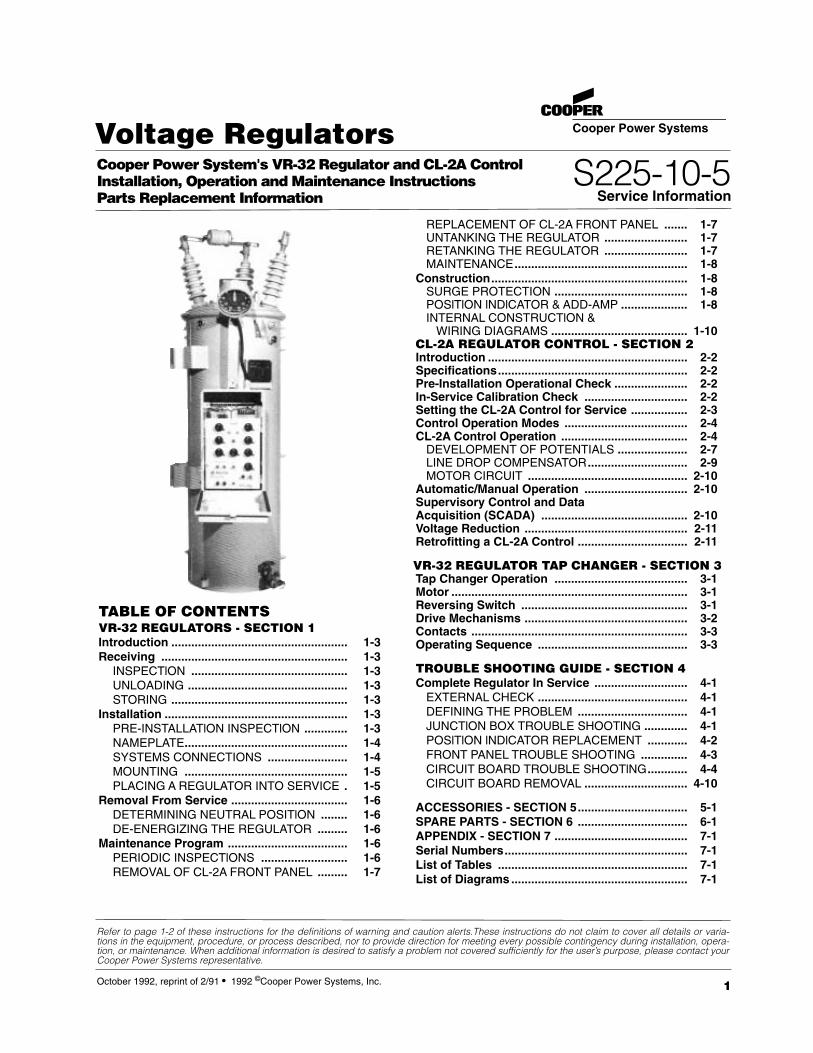
Figure 1-2Features of the VR-32 Voltage Regulator.
DEFINITlONS OF ALERTS: PLEASE READ THE FOLLOWING CAREFULLY AND HEED THE WARNINGSCAUTlONS, AND NOTICES HEREIN.
NOTICE: A NOTICE describes a situation, which ifnot avoided could result in damage to the equipmentwith no likelihood of personal injury.
1. CLAMP-TYPE TERMINALS2. THREADED-STUD BUSHING TERMINALS3. BUSHINGS4. POSITlON INDICATOR5. REGULATOR LIFTING LUGS6. UPPER FILTER PRESS CONNECTION7. ARRESTER MOUNTING BOSSES8. BALL-TYPE OlL SIGHT GAUGE9. CONTROL CABLE
10. NAMEPLATES (2)11. GROUND BOSSES (2)12. DRAIN VALVE & OlL SAMPLING DEVICE13. BOLT-DOWN PROVISlONS14. CONTROL15. CONTROL ENCLOSURE16. POLE-TYPE MOUNTING BRACKETS17. ENCLOSURE SUPPORT BAR18. HANDHOLE COVER19. MOV-TYPE SERIES ARRESTER20. JUNCTION BOX21. INTERNAL ASSEMBLY LIFTING LUGS22. PANEL-TYPE RADIATORS (Not Shown)

S225-10-5
1-3
VR-32 VOLTAGE REGULATORS - Section 1
INTRODUCTION
Cooper Power System's VR-32 feeder voltage regulatorsare regulating auto-transformers. They regulate line voltagefrom ten-percent raise (boost) to ten-percent lower (buck) in32, approximately 5/8 % steps.
Cooper Power System's regulators are supplied with thefollowing standard features:
Dual-rated 55/65oC rise.ADD-AMP capabiilty.Unit construction.Sealed-tank construction.Pressure relief device.High-creep bushings with clamp-type terminals.MOV-type external series arresters.Shunt arrester mounting bosses.Two nameplates.Gil sight gauge.Upper filter press connection.Drain valve and oil-sampling device.
The 65oC rise insulation system and the sealed-tank con-struction allow for a BONUS CAPACITY 12% above the55oC normal rating without loss of normal insulation life. TheBONUS CAPACITY is stated on the nameplate (such as167/187 kVA for a nominal 167 kVA regulator), and is avail-able when the ADD-AMP feature is not in use. All CooperPower System's regulators are manufactured and tested toANSI standard C57.15.
The unit construction, which suspends the internalassembly and the control enclosure form the cover, allowsfor ease of inspection and maintenance.
There are three types of step-voltage regulators: source-side series winding, load-side series winding, and seriestransformer. Cooper Power System's Regulators are usuallyequipped with an equalizer winding. The nameplates locat-ed on the tank and control box clarify the power circuitinvolved.
RECEIVING
InspectionPrior to shipment, the regulator is thoroughly tested andinspected at the factory. Immediately upon receipt of theregulator shipment, before unloading, a thorough inspectionshould be made for damage, evidence of rough handling, orshortages. The position indicator, junction box, arrester,radiators, and bushings should all be inspected for evidenceof damage. Should this initial inspection reveal evidenceof rough handling, damage, or shortages, it should benoted on the Bill of Lading and a claim should immedi-ately be made with the carrier. Also, notify Cooper PowerSystems, 2300 Badger Drive, Waukesha, Wisconsin 53188,attention Service Manager.
UnloadingWhen an overhead crane is used for unloading, the regula-tor must be lifted by means of a sling and spreader bar uti-lizing the tank-mounted lifting lugs which are shown inFigure 1-2. Do not lift the entire unit with the lifting eyes onthe cover. The lifting eyes are only to be used to untank theinternal assembly which is attached to the cover.
CAUTION: Do not subject tap changer to tempera-tures above 150oF. To do so may cause damage to
the contact panels, resulting in misalignment of the con-tacts.
!
WARNING: The cover may fracture if the cover-mounted lifting eyes are used to fit the entire unit. Lift
the entire unit only with the tank-mounted lifing lugs.!
StoringIf the regulator is not to be placed into immediate use, it can bestored with minimal precautions. Locate the unit where the possibil-ity of mechanical damage is minimized.
INSTALLATlONPre-installation InspectionBefore connecting the regulator to the line, make the followinginspection:1 . Check the oil sight gauge. Look for visible signs of oiI leakage.2. Examine the series arrester for damage. If damaged, install a
new arrester of the same voltage rating.3. Inspect the porcelain bushings for damage or leaking seals. If
there is a suspicion that moisture has entered the unit, removethe handhole cover and inspect for evidence of moisture such asrust or watertracks in the oil. If moisture has entered the tank, drythe regulator and filter the oil before putting the unit in service.The oil must test 26 kV minimum in a standard gap (ASTM D877). Be sure to properly replace the handhole cover.
4. If the regulator has been stored for some time, test the dielectricstrength of the oil according to ASTM D-877.
5. The regulator may be energized at rated line voltage (with caution)and an operational check, page 1-8, can be performed. (Thisprocedure is optional.)
6. A Hi-pot test may be done to insure adequate electrical clearanc-es to ground. (This procedure is optional.)

1-4
Figure 1-3.Nameplate.
Figure 1-4.Typical connections diagrams.
VR-32 Regulator and CL-2A Control
WARNING: Connect the "S" bushing to theSOURCE, the "L" bushing to the LOAD, and the
"SL" bushing to NEUTRAL. To do otherwise may causeexcessively high or low voltage on the load side of theregulator or cause severe damage to the regulator.
!
NameplateThe VR-32 nameplate (Figure 1-3) prominently displays the55/65°C temperature rise rating of the regulator. The sealed-tank system along with the 65°C rise winding insulation allowsthe regulator to be used at this dual rating. This provides anadditional 12 percent capacity without loss of normal insulationlife.
The nameplate is stamped with pertinent rating informationand includes the schematic diagram of the VR-32 internaldesign. Refer to the nameplate to determine the correct adjust-ment for the required regulated load voltage. A movable peg onthe nameplate indicates the tap and load voltage in use.
Systems ConnectionsA regulator can regulate a single-phase circuit, or one phase ofa three-phase wye or delta circuit. Two regulators connectedphase-to-phase in open-delta, or three regulators connectedphase-to-phase in closed-delta, can regulate a three-phase,three-wire delta circuit. When connected in wye, three regula-tors can regulate a three-phase, four-wire multi-grounded wyecircuit. Three regulators cannot be connected in wye on three-phase, three-wire circuits because of the probability of neutralshift. Typical connection diagrams are illustrated in Figure 1-4.

S225-10-5
1-5
CAUTION: When installing a regulator, solidlyground both the regulator tank AND the control.
Failure to do so may cause damage to the regulator and/orcontrol due to current surges and may subject personnelto electrical shock.
!
WARNING: Closing the bypass switch withthe tap changer off neutral will short circuit part
of the series winding. Before closing the bypassswitch, the regulator must be on NEUTRAL and thecontrol switch set to OFF.
!
Procedure A should be followed when one bypass switchand two disconnect switches are used. Procedure B shouldbe followed when a regulator bypass-disconnect switch isused.
Placing A Regulator Into ServiceRegulators can be placed in service without interruptingload continuity.
Figure 1-5.Elevating structure.
Figure 1-6.Knife switches and TB1 (with optional V6 knife switch andRCT2).
PROCEDURE A: ONE BYPASS SWITCH AND TWODISCONNECT SWITCHES1. Verify from the regulator nameplate that the control circuit is
connected for the proper regulated load voltage.2. Set the POWER switch to OFF and the CONTROL switch to
OFF.3. The knife switches on the back panel should be set with the V1
(potential switch) [and V6 if present] closed (pushed in), andthe C (CT shorting switch) open (pulled out). See Figure 1 -5.
4. Close the SOURCE-LOAD (SL) disconnect switch. (Delta appli-cations only).
5. Close the SOURCE (S) disconnect switch.6. Set the POWER switch to INTERNAL and the CONTROL
switch to MANUAL.7. Lift the RAISE-LOWER switch to operate the tap changer two
or three steps, then depress the RAISE-LOWER switch toreturn the tap changer to neutral position. (These steps verifythe mechanism is functional.) When on neutral, the NEUTRALLAMP will glow and the position indicator will point to zero.
8. With the regulator in neutral position, set the CONTROLswitch to OFF, set the POWER switch to OFF, open the V1knife switch (back panel) [and V6 if present], and remove the6A motor fuse.
NOTE: Individual switches are shown for the bypass anddisconnect functions. However, a regulator-bypass-discon-nect switch can be used in each phase to perform thebypassing and disconnecting operations in sequence. Eachof these switches replaces one bypass and two disconnectswitches shown in the diagrams.
MountingA regulator can be mounted on a pole, cross arm platform,or elevating structure (optional). Regulators are normallyprovided with either pole mounting brackets or a stationplatform according to the rating. This information is avail-able in Table 3-1, page 3-1, by noting the S(Substation) suf-fix to the kVA. A Cooper Power System's elevating structure(Figure 1-4) can be used to simplify substation installationof regulators requiring a specific live part-to-ground clear-ance.
The regulator control can be mounted on the regulatortank, or at a point remote from the unit. Rubber-coveredcable is available in lengths of 15, 20, 25, 30, and 35 ft forinterconnection between the control and the regulator.
A threaded stud is provided at the bottom of the controlenclosure and a ground pad is provided on the side of theenclosure, for grounding purposes.

1-6
VR-32 Regulator and CL-2A Control
WARNING: Closing the bypass switch with thetap changer off neutral will short circuit part of the
series winding. Before closing the bypass switch, theregulator must be on NEUTRAL and the control switchset to OFF.
!
9. Close the LOAD (L) disconnect switch.10. Open the BYPASS Switch.11. Replace the 6A motor fuse, close the V1 knife switch [and
V6 if present] and set the POWER switch to INTERNAL.12. Set the AUTO/OFF/MANUAL switch to AUTO.13. Set the VOLTAGE setting to call for one step of voltage
correction.14. If satisfactory, call for one step of voltage correction in the
opposite direction.15. If both operations are satisfactory, set the VOLTAGE SET-
TING control at the desired level.
PROCEDURE B: REGULATOR BYPASSDISCONNECT SWITCH
1. Verify from the regulator nameplate that the control circuitis connected for the proper regulated load voltage.
2. Set the AUTO/OFF/MANUAL switch to MANUAL and thePOWER switch to EXTERNAL.
3. The knife switches on the back panel should be set withthe V1 (potential switch) [and V6 if present] open (pulledout), and the C (CT shorting switch) closed (pushed in).See Figure 1-6.
4. Apply 120 volts to the EXTERNAL SOURCE terminals, if120 volts is available. If not, proceed to Step 7, below.
5. Lift the RAISE/LOWER switch to operate the tap changertwo or three steps, then depress the RAISE/LOWERswitch to return the tap changer to neutral position.(These steps verify the mechanism is functional.) Whenon neutral, the NEUTRAL LAMP will glow and the posi-tion indicator will point to zero.
6. Remove the 120 volts from the EXTERNAL SOURCE ter-minals.
7. With the regulator in neutral position, set theAUTO/OFF/MANUAL switch to OFF, set the POWERswitch to OFF, and remove the 6A motor fuse.
8. Close the SOURCE-LOAD (SL) disconnect switch. (Deltaapplications only).
9. Close the regulator bypass-disconnect switch.10. Replace the 6A motorfuse, close the V1 knife switch [and
V6 if present], open the C knife switch, and set thePOWER switch to INTERNAL.
11. Set the AUTO/OFF/MANUAL switch to AUTO.12. Set the VOLTAGE SETTING to call for one step of volt-
age correction.13. If satisfactory, call for one step of voltage correction in the
opposite direction.14. If both operations are satisfactory, set the VOLTAGE
SETTING control at the desired level.
REMOVAL FROM SERVICE
Determining Neutral Position
Return the regulator to neutral. The regulator can be safelyremoved from service without interrupting load continuity onlyon the neutral position. It is wise to employ more than onemethod to determine whether a regulator is on neutral.
WARNING: A regulator should be bypassed withthe line energized ONLY if BOTH the position indi-
cator AND the neutral light indicate NEUTRAL. If both donot indicate NEUTRAL, the line should be de-energizedto avoid shorting part of the series winding.
!
WARNING: Always use the CONTROL switch(labeled AUTO/REMOTE-OFF-MANUAL) to oper-
ate the regulator, not the POWER switch. Failure to doso may result in the tap changer stepping off of neutralimmediately upon being energized.
!
To Return The Regulator To Neutral1. Use the control to RAISE or LOWER the regulator until it is
in the neutral position.2. When on NEUTRAL, the NEUTRAL LAMP will light and the
POSITlON INDICATOR will point to zero.3. To stop the regulator on the neutral position, the CONTROL
switch should be turned to OFF during the switching opera-tion from position “1 “ to position zero. Switching to OFFprior to reaching the neutral position prevents overshoot.
4. The POSITlON INDICATOR and NEUTRAL LIGHT MUSTBOTH indicate neutral.
De-energizing The RegulatorOnce it has been established that the regulator is on neutral,immediately proceed with the following steps:1. Turn the CONTROL switch to OFF.2. Turn the control POWER switch to OFF.3. Open the V1 knife switch (and V6 if present) on the back
panel (Figure 1-5).4. Remove the 6A motor fuse. 5. Close the BYPASS switch. 6. Open the SOURCE(S) disconnect switch. 7. Open the LOAD (L) disconnect switch.8. Open the SOURCE-LOAD (SL) disconnect switch. (Delta
application only.)Note: If a regulator bypass disconnect is used in place of
three separate switches, steps 5, 6, and 7 are carried out inone operation.
MAINTENANCE PROGRAMPeriodic Inspections
Step-type voltage regulators are designed to provide manyyears of trouble-free operation. Proper operation of the regula-tor can be checked without removing the unitfrom service.Using the manual mode of operation, run the regulator severalsteps in the raise direction, and then turn the control back toauto. After the time delay programmed into the control expires,the regulator should return within bandwidth (which will nor-mally be the same position you started from, unless the incom-ing voltage is currently varying). When this has been complet-ed, use the manual mode of operation to run the regulator sev-eral steps in the lower direction, and then turn the control backto auto. After the time delay, the regulator should return backwithin bandwidth.
If the regulator will not operate properly, a substitute controlcan be tried before removing the unit from service. Refer tothe following sections for proper procedures on removing andreplacing the CL-4C Control.

S225-10-5
1-7
Figure 1-7.Untanking.
WARNING: Push the C shorting switch closedbefore attempting to remove the fanning strip.
Failure to do so will open the regulator CT circuit andmay produce a flashover on the control.
!
2. Pull open the disconnect switch, V1 (and V6 if present).This de-energizes the CL-2A front panel.
3. Loosen the screws on the interconnecting terminal strip(TB2) at the bottom of the back panel.
4. Pull the fanning strip free from the terminal strip.The CL-2A can now be lifted off its hinges. Care should be
taken to prevent damage to the CL-2A front panel while intransit and/or storage.
Replacement of CL-2A Front PanelTo replace a CL-2Afront panel in the control enclosure, followthe procedure outlined below:
1. Engage the front panel on the enclosure hinges.2. Insert the fanning strip from the front panel wiring harness
under the TB2 terminal block screws, matching terminalindentification.
3. Tighten the screws on the interconnecting terminal block.4. Push closed the disconnect switch, V1 (and V6 if present).5. Pull open the current shorting switch, C.6. Close the panel and tighten panel locking screw.
Untanking The Regulator1. Manually run the tap changer to neutral, if possible. If not
possible, note position indicator reading before proceed-ing to untank.
2. Remove the two mounting bolts holding the control cabi-net to tank.
3. Remove the series arrester. Release internal pressureusing the pressure relief device on the side of the regula-tor.
4. Free cover by removing clamping ring or cover bolts.5. Attach sling or hooks with spreader bar (Figure 1-7) to lift-
ing eyes and raise the cover, with the attached core-and-coil assembly, until the top of the coil is approximatelyone inch under oil. The control cabinet should be guidedto avoid snagging during lifting.
Since the usable life of a regulator is affected by its applica-tion, it may be desirable to periodically remove the regulator-from service and untank the unit to verify contact wear, oildielectric, etc. The time for this will vary, depending on a spe-cific user’s past experience.
Removal of CL-2A Front PanelThe CL-2A front panel may be removed from the regulatorwith the regulator energized.
To open the front panel, unscrew the panel locking screw onthe left side of the panel. This allows the control to swing openon its hinges. With the control open, the back panel is readilyaccessible. The design of the control enclosure, back panel,and front panel enable easy replacement of the front panel,leaving the back panel, control enclosure, and cable intact. Toremove the front panel, proceed as follows:
1 . Push closed the current shorting switch, C. This shortsout the secondary of the regulator C.T.
CAUTION: Before intanking a fan-cooled regula-tor, (1) lower the oil level below the thermometer,
then (2) remove the thermometer will. Failure to do so willresult in damage to the thermometer will and/or spillageof oil when the internal assembly is lifted.
!
It is recommended that the main core-and-coil assembly neverbe removed from the oil, except when a winding failure occurs.Blocking between the cover and tank lip should be employed tosuspend the core-and-coil assembly within the oil until inspectionof the tap changer or other maintenance is complete.
Retanking The Regulator Retank the regulator as follows:1. Be sure the position indicator shows the present position of
the tap changer. If not, remove the indicator cable in thejunction box from the position indicator shaft after looseningthe set screw. Rotate the indicator shaft until the proper posi-tion is reached, then tighten the set screw. Verify coordina-tion of position indicator with tap changer in neutral position(control neutral light on).
2. Check the gasket seat surfaces on the cover and tank, andwipe clean. Wipe the gasket and position it on the tank lip.Loosen horizontal side channel bolts to insure proper seat-ing of regulator in tank and cover seal.

1-8
VR-32 Regulator and CL-2A Control
3. Raise the cover assembly and attached components overthe tank. Make certain of proper orientation.
4. Lower the unit, positioning the channels in the tank guides.Guide the control cabinet onto its brackets.
5. Seat the unit in the tank. Tighten the cover clamps or boltsand replace the control mounting bolts.NOTE: Tap the cover with a rubber hammer around theedge to properly seal the gasket while tightening the coverband.
6. Check and retighten horizontal side channel bolts throughhandhole, if required.
MaintenanceThe following is the recommended maintenance program for aregulator that has been untanked:
1. Check all connections for tightness.2. Check all contacts for wear (refer to S225-10-2).3. Avoid removing the main core-and-coil assembly from the
oil, except when a winding failure occurs. Blocking betweenthe cover and tank lip should be employed to suspend thecore-and-coil assembly within the oil until inspection of thetap changer or other maintenance is complete.
WARNING: When the internal assembly is liftedfor inspection or maintenance, blocking should be
placed between the cover and the top of the tank tokeep the assembly from falling should lifting apparatusfail.
!
If it is necessary to remove the main core-and-coil assemblyfrom the oil, the following steps should be followed.A. The tap changer must not be subjected to temperatures
above 66oC. (150oF). It must be removed if the unit isbaked at higher temperatures.
B. If the unit is out of oil more than four hours, it must berebaked for a minimum of 24 hours at 100oC (212oF).The maximum number of times a unit should be rebakedis twice.
C. Within four hours after bake, the unit should be retankedand filled with oil.
D. It is recommended that a vacuum be pulled on the unitfor at least one hour (2 mm. of vacuum or better) after theunit is completely refilled with oil. If vacuum processing isnot available, allow the entire internal assembly to soakin the oil for at least five days before energizing.
E. Do not test the unit until either the vacuum processing orthe soaking has been completed.
4. Consider upgrading controls to latest design.
CO N ST R U CTIO NSurge Protection SERIES SURGE ARRESTERAll VR-32 regulators are equipped with a bypass arrester con-nected across the series winding between the source (S) andload (L) bushings. This bypass arrester limits the voltage devel-oped across the series winding during lightning strikes, switch-ing surges, and line faults. The series surge arrester can beseen in Figure 1-2. A MoV-type series surge arrester of 2.2 kVoffers series winding protection on all regulators except thoserated over 14,400 volts which have a 3/4.5-kV MoV-type seriessurge arrester.
SHUNT ARRESTERSA shunt arrester is an optional accessory on the VR-32 regula-tor for protection of the shunt winding. The shunt arrester is adirect connected arrester mounted on the tank and connected between
TABLE 1-1Shunt Arrester Application Data.
the “L” bushing and ground. For additional protection a shuntarrester may also be installed between the S (source) bushingand ground.
For best results, locate these arresters on the mounting padsprovided on the tank near the bushing. Ground the arrester andthe regulator tank to the same ground connection using theshortest cable possible. Shunt arrester application data is listedin Table 1-1.
Nominal System Voltages Recommended(volts) MOV
Regulator ShuntVoltage Delta or Multi-Grounded ArresterRating Single-Phase Wye Ratings
(kV)
2500/4330Y 2400 2400/41602500 2500/4330 34160 4160/7200
5000/8660Y 4330 4330/75004800 4800/8320 65000 5000/86606900 6900/11950
7620/13200Y 7200 7200/12470 97620 7620/132007970
7970/13800 101200012470
13800 13200 151380014400
13800/2390014400/24940Y 14400/24940 1819920/34500GrdY 19920/34500 27
Position Indicator & ADD-AMP CapabilityThe position indicator (Figure 1-8) is mounted on a junction boxon the cover of the regulator and is directly connected to the tapchanger by a flexible drive shaft passing through the junctionbox and terminal board via a sealing gland.
The indicator face is graduated in steps, numbered 1 through16, on each side of zero, which designates neutral. Drag handsindicate the maximum and minimum positions attained duringraise and lower operations. The drag hands are automaticallyreset around the position indicator hand by operating the draghand reset switch on the control front panel.
The ADD-AMP feature of VR-32 regulators allows increasedcurrent capacity by reducing the regulation range. This isaccomplished by setting limit switches in the position indicatorto prevent the tap changer from traveling beyond a set positionin either raise or lower directions. The limit switches havescales graduated in % regulation, and are adjustable to specificvalues of 5, 6-1/4, 7-1/2, 8-3/4, and 10% regulation to alter theregulation range. The five possible load current ratings associ-ated with the reduced regulation ranges are summarized inTable 1-2. At each setting a detent stop provides positiveadjustment. Settings other than those with stops are not recom-mended. The raise and lower limits need not be the samevalue.

S225-10-5
1-9
Setting The Limit SwitchesBefore setting the limit switches, be sure the new settingswill not conflict with the present tap changer position. Do notset the switches below the indicated tap changer position.For example, if the indicator hand is at step 12 and thechange to be made is from plus or minus 10% (step 16) toplus or minus 5% (step 8), run the tap changer back to step7 or less, manually. Then set the limit switches for plus orminus 5% regulation.
Limit switches should be set in anticipation of the maxi-mum deviation of primary voltage. For example, on a circuitwhere 7200 volts is to be maintained, plus or minus 10% willpermit voltages between 6480 and 7920 to be regulatedeffectively. For voltages outside of this range, the regulatorwill not be able to return the voltage to the preselected level,in this case 7200 volts. The tap changer will have stepped tothe maximum tap position and will be unable to regulate fur-ther. Five % regulation would accommodate circuit voltagesbetween 6840 and 7560, maintaining 7200 volts for all volt-ages in this range.
To set the limit switches. follow this two-step procedure:1. Loosen the captive bezel securing screws and swing the
bezel open.2. Lift the limit switch adjustment lever free of the detent and
slide it to the new setting allowing the lever to snap intothe detent stop.
Figure 1-8.Position Indicator.
TABLE 1-2ADD-AMP Capabilities.
**55/65oC rise rating on VR-32 regulators gives an additional 12%increase in capacity if the tap changer’s maximum current rating hasnot been exceeded. For loading in excess of the above values pleaserefer to the factory.
Load Current Ratings (amps)Rated Rated Regulation RangeVolts kVA
± 10%** ± 8-3/4% ± 7% ± 6-1/4% ± 5%25 100/112 110 120 135 16050 200/224 220 240 270 32075 300/336 330 360 405 480
100 400/448 440 480 540 6402500 125 500/560 550 600 668 668
167 668 668 668 668 668250 1000/1120 1000 1000 1000 1000333 1332/1492 1332 1332 1332 1332
416.3 1665/1865 1665 1665 1665 166525 50/56 55 60 68 8050 100/112 110 120 135 160
100 200/224 220 240 270 320125 250/280 275 300 338 400
5000 167 334/374 367 401 451 534250 500/560 550 600 668 668333 668 668 668 668 668
416.3 833/900 833 833 833 83338.1 50/56 55 60 68 8057.2 75/84 83 90 101 12076.2 100/112 110 120 135 160114.3 150/168 165 180 203 240167 219/245 241 263 296 350
7620 250 328/367 361 394 443 525333 438/491 482 526 591 668
416.3 548/614 603 658 668 668500 656/668 668 668 668 668667 875/900 875 875 875 875833 1093/1224 1093 1093 1093 109369 50/56 55 60 68 80
138 100/112 110 120 135 16207 150/168 165 180 203 24276 200/224 220 240 270 32
13800 414 300/336 330 360 405 48500 362/405 398 434 489 579552 400/448 440 480 540 64667 483/541 531 580 652 668833 604/668 664 668 668 66872 50/56 55 60 68 80
144 100/112 110 120 135 16288 200/224 220 240 270 320333 231/259 254 277 312 37416 289/324 318 347 390 462
14400 432 300/336 330 360 405 480500 347/389 382 416 468 555576 400/448 440 480 540 64667 463/519 509 556 625 668720 500/560 550 600 668 668833 578/647 636 668 668 66850 25.1/28 28 30 34 40
100 50.2/56 55 60 68 80200 100.4/112 110 120 135 16
19920 333 167/187 184 200 225 267400 200.8/224 220 240 270 32500 250/280 275 300 338 400667 335/375 369 402 452 536833 418/468 460 502 564 668

1-10
Figure 1-9.Power circuit - series winding located on the source-side.(ANSI Type B)
VR-32 Regulator and CL-2A Control
INTERNAL CONSTRUCTION &WIRING DIAGRAMSThe main core-and-coil assemblies are of the shell-form con-figuration. The series winding on the input (source) side of theregulator (Figure 1-9) allows all windings (control, shunt, andseries) to be located in one coil. The load voltage is readdirectly by the control winding.
Regulators that have the series winding on the output (load)side (Figure 1-10) possess an identical coil configuration, buthave a separate potential transformer in lieu of a control wind-ing installed on the output side. This voltage is then applied tothe sensing circuit of the control.
The control winding is wound on the core to obtain a supplyvoltage for the tap changer motor and the control sensing cir-cuits. Taps are available on this winding for large-step voltage-ratio correction.
The shunt winding is wound over top of the control windingwith the series winding wound over top of the shunt winding.Most regulators, depending upon the rating, have an equalizerwinding. If applicable, the equalizer winding is wound on theoutside of the coil over the series winding.
Figure 1-11 shows a regulator power circuit with a seriestransformer. This design is utilized when the load current ratingexceeds the tap changer rating. Figure 1-12 shows the internalconstruction of this regulator. In this type of design, the seriestransformer winding losses are a function of the load aloneand are independent of the tap position. Because of this, limit-ing the range of voltage regulation does not reduce losses
and therefore, the ADD-AMP feature is not applicable.The preventive auto or bridging reactor is a core-form design,
consisting of a coil on each leg of the core. The inside half of onecoil is connected to the outside half of the other coil and viceversa, providing equal current in each half of the reactor winding.This interlacing of the two coils reduces the interwinding leakagereactance to a very low value. The reactor is completely isolatedfrom ground by stand-off insulators since the reactor coil is atline voltage above ground. The reactor core, core clamps, andother associated parts approach this level.
The current transformer is a toroid, through which the load cur-rent passes. It furnishes a current proportional to load current tothe line-drop compensator circuit in the control and to optionalmetering packages.
The tap changer enables the regulator to provide regula:ion insmooth, accurately proportioned steps at a controlled speed thatminimizes arcing and extends contact life. Four different tapchangers are used throughout the line of regulator ratings.Figures 1-13 through 1-16 illustrate typical internal wiringschemes of the various types of regulator constructions. Most ofthe wiring is on the tap changer itself. Application, troubleshoot-ing, and operation of the spring- and direct-drive tap changersand related components are covered extensively in ServiceManual S225-10-2.
The terminal board inside the junction box on the cover con-nects the internal tank wiring to the position indicator and con-trol. The junction box wiring is shown in Figure 4-1, page 4-2.