Embed Size (px)
Citation preview
USER'S MANUAL Vol.1 BasicPlease read this user's manual thoroughly to ensure correct usage through understanding.
BEDIENUNGSANLEITUNG Teil 1 GrundlagenBitte lessen Sie diese Benutzerhandbuch zugunsten der korrekten Bedienung aufmerksam.
MANUEL D'UTILISATION Vol.1 FondementsNous vous recommandons de lire attentivement ce manuel pour bien assimiler le fonctionnement de l'appareil.
MANUALE D'ISTRUZIONI Vol.1 Informazioni di baseVi preghiamo voler leggere attentamente il manuale d'istruzioni in modo tale da poter comprendere quanto riportatoai fini di un corretto utilizzo del proiettore.
MANUAL DE USUARIO Vol.1 BásicoLea cuidadosamente este manual del usuario para poder utilizar corretamente el producto.
GEBRUIKSAANWIJZING Vol.1 BasisLees voor het qebruik alstublieft deze handleiding aandachtig door, om volledig profijt te hebben van deuitgebreide mogelijkheden.
BRUKERHÅNDBOK Vol.1 GrunnleggendeVennligst les denne bruksanvisningen grundig for å være garantert driftssikker bruk.
NSTRUÇÕES DO PROPRIETÁRIO Vol.1 BásicoPara assegurar o uso correto do equipamento, por favor leia atentamente este manual do utilizador.
EN
GL
ISH
DE
UT
SC
HF
RA
NÇ
AIS
ITA
LIA
NO
ES
PA
ÑO
LNE
DERL
ANDS
NO
RS
KP
OR
TG
ÊS
Liquid Crystal Projector
CP-S225/CP-X275(CP-S225WA/CP-X275WA)
00CP-S225/X75/WBasic/再 02.10.16 5:18 PM ページ2
1
EN
GL
ISH
LCD Projector CP-S225/CP-X275
USER'S MANUAL USER'S MANUAL Vol.1 (Basic)
Page
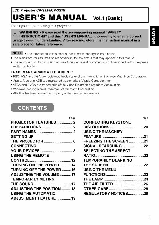
PROJECTOR FEATURES................2PREPARATIONS ..............................2PART NAMES...................................4SETTING UPTHE PROJECTOR ............................6CONNECTINGYOUR DEVICES................................8USING THE REMOTECONTROL.......................................12TURNING ON THE POWER ...........14TURNING OFF THE POWER .........16ADJUSTING THE VOLUME ...........17TEMPORARILY MUTINGTHE SOUND....................................17ADJUSTING THE POSITION..........18USING THE AUTOMATICADJUSTMENT FEATURE ..............19
Page
CORRECTING KEYSTONEDISTORTIONS ................................20USING THE MAGNIFYFEATURE........................................21FREEZING THE SCREEN ..............21SIGNAL SEARCHING.....................22SELECTING THE ASPECTRATIO..............................................22TEMPORARILY BLANKINGTHE SCREEN..................................22USING THE MENUFUNCTIONS....................................23THE LAMP ......................................24THE AIR FILTER.............................26OTHER CARE.................................28REGULATORY NOTICES...............29
CONTENTS
Thank you for purchasing this projector.
• The information in this manual is subject to change without notice.• The manufacturer assumes no responsibility for any errors that may appear in this manual • The reproduction, transmission or use of this document or contents is not permitted without express
written authority.
TRADEMARK ACKNOWLEDGEMENT :• PS/2, VGA and XGA are registered trademarks of the International Business Machines Corporation.• Apple, Mac and ADB are registered trademarks of Apple Computer, Inc.• VESA and SVGA are trademarks of the Video Electronics Standard Association.• Windows is a registered trademark of Microsoft Corporation.• All other trademarks are the property of their respective owners.
NOTE
WARNING • Please read the accompanying manual “SAFETYINSTRUCTIONS” and this “USER'S MANUAL” thoroughly to ensure correct
usage through understanding. After reading, store this instruction manual in asafe place for future reference.
01CP-S225/X75/Vol1/E/最終 02.10.17 10:24 AM ページ1
2
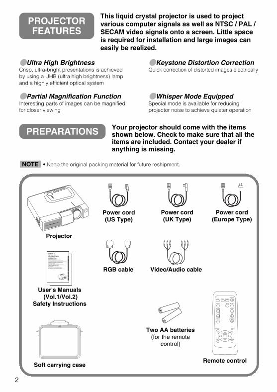
Ultra High BrightnessCrisp, ultra-bright presentations is achievedby using a UHB (ultra high brightness) lampand a highly efficient optical system
Partial Magnification FunctionInteresting parts of images can be magnifiedfor closer viewing
Keystone Distortion CorrectionQuick correction of distorted images electrically
Whisper Mode EquippedSpecial mode is available for reducingprojector noise to achieve quieter operation
PREPARATIONS Your projector should come with the itemsshown below. Check to make sure that all theitems are included. Contact your dealer ifanything is missing.
Projector
USER'S MANUAL Vol.1 BasicPlease read this user's manual thoroughly to ensure correct usage through understanding.
BEDIENUNGSANLEITUNG Teil 1 GrundlagenBitte lessen Sie diese Benutzerhandbuch zugunsten der korrekten Bedienung aufmerksam.
MANUEL D'UTILISATION Vol.1 FondementsNous vous recommandons de lire attentivement ce manuel pour bien assimiler le fonctionnement de l'appareil.
MANUALE D'ISTRUZIONI Vol.1 Informazioni di baseVi preghiamo voler leggere attentamente il manuale d'istruzioni in modo tale da poter comprendere quanto riportatoai fini di un corretto utilizzo del proiettore.
MANUAL DE USUARIO Vol.1 BásicoLea cuidadosamente este manual del usuario para poder utilizar corretamente el producto.
GEBRUIKSAANWIJZING Vol.1 BasisLees voor het qebruik alstublieft deze handleiding aandachtig door, om volledig profijt te hebben van deuitgebreide mogelijkheden.
BRUKERHÅNDBOK Vol.1 GrunnleggendeVennligst les denne bruksanvisningen grundig for å være garantert driftssikker bruk.
NSTRUÇÕES DO PROPRIETÁRIO Vol.1 BásicoPara assegurar o uso correto do equipamento, por favor leia atentamente este manual do utilizador.
EN
GL
ISH
DE
UT
SC
HF
RA
NÇ
AIS
ITA
LIA
NO
ES
PA
ÑO
LNE
DERL
ANDS
NO
RS
KP
OR
TG
ÊS
Liquid Crystal Projector
CP-S225/CP-X275(CP-S225WA/CP-X275WA)
User's Manuals(Vol.1/Vol.2)
Safety Instructions
Soft carrying case
Power cord (US Type)
Power cord(UK Type)
Power cord(Europe Type)
RGB cable
VIDEO
ASPECT
MUTE
KEYSTONEFREEZE
OFF
ON
MENUPOSITION
ENTER
ESC RESET
VOLUMEMAGNIFY
AUTO BLANK
RGB SEARCHSTANDBY/ON
Remote control
Two AA batteries(for the remote
control)
Video/Audio cable
PROJECTORFEATURES
This liquid crystal projector is used to projectvarious computer signals as well as NTSC / PAL /SECAM video signals onto a screen. Little spaceis required for installation and large images caneasily be realized.
• Keep the original packing material for future reshipment.NOTE
01CP-S225/X75/Vol1/E/最終 02.10.17 10:24 AM ページ2
3
EN
GL
ISH
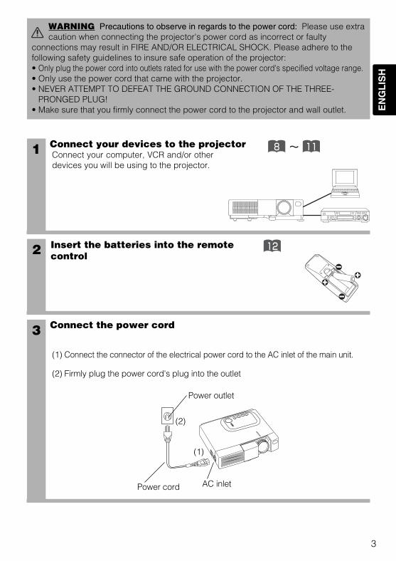
1 Connect your devices to the projectorConnect your computer, VCR and/or otherdevices you will be using to the projector.
Insert the batteries into the remotecontrol2 12
3 Connect the power cord
(1) Connect the connector of the electrical power cord to the AC inlet of the main unit.
(2) Firmly plug the power cord's plug into the outlet
WARNING Precautions to observe in regards to the power cord: Please use extracaution when connecting the projector's power cord as incorrect or faulty
connections may result in FIRE AND/OR ELECTRICAL SHOCK. Please adhere to thefollowing safety guidelines to insure safe operation of the projector:• Only plug the power cord into outlets rated for use with the power cord's specified voltage range.• Only use the power cord that came with the projector.• NEVER ATTEMPT TO DEFEAT THE GROUND CONNECTION OF THE THREE-
PRONGED PLUG!• Make sure that you firmly connect the power cord to the projector and wall outlet.
~8 11
(1)
(2)
Power outlet
Power cord AC inlet
01CP-S225/X75/Vol1/E/最終 02.10.17 10:24 AM ページ3
4
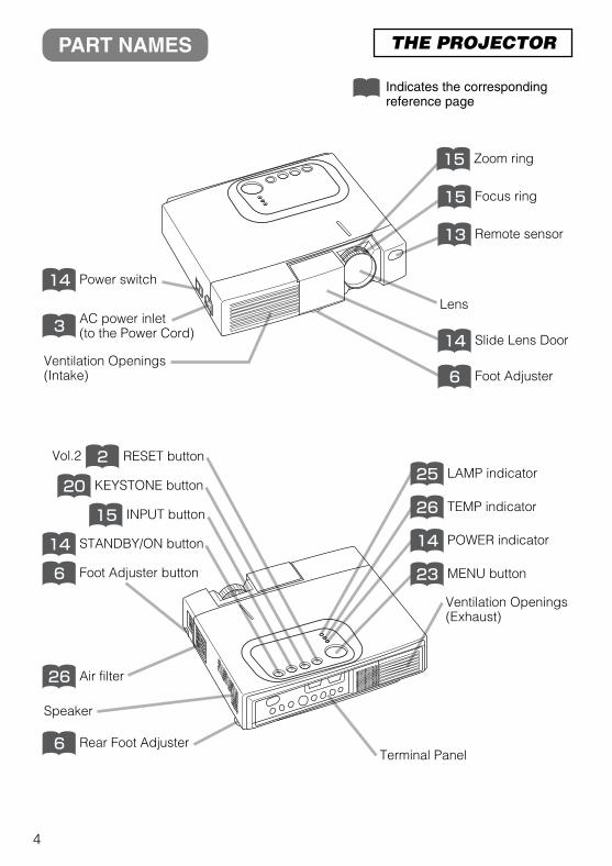
PART NAMES THE PROJECTOR
Indicates the correspondingreference page
AC power inlet(to the Power Cord)3
Ventilation Openings(Intake)
Power switch14
Zoom ring15
Focus ring15
Remote sensor13
Lens
Slide Lens Door14
Foot Adjuster6
Air filter26
KEYSTONE button20
2
STANDBY/ON button14
INPUT button15
RESET button
Speaker
Foot Adjuster button6
Rear Foot Adjuster6
LAMP indicator25
TEMP indicator26
POWER indicator14
MENU button23
Ventilation Openings(Exhaust)
Terminal Panel
Vol.2
01CP-S225/X75/Vol1/E/最終 02.10.17 10:24 AM ページ4
5
EN
GL
ISH
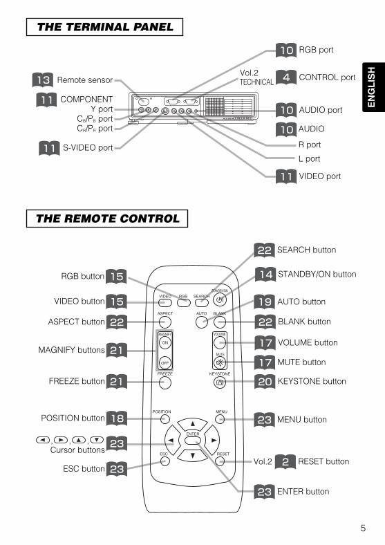
THE REMOTE CONTROL
THE TERMINAL PANEL
STANDBY/ON button14
VIDEO button 15
MENU button23
10
RGB button 15
BLANK button22
SEARCH button22
VOLUME button17
MUTE button17
KEYSTONE button20
ASPECT button 22
AUTO button19
MAGNIFY buttons 21
FREEZE button 21
POSITION button 18
ESC button 23
, , ,Cursor buttons
23
RESET button2
ENTER button23
VIDEO
ASPECT
MUTE
KEYSTONEFREEZE
OFF
ON
MENUPOSITION
ENTER
ESC RESET
VOLUMEMAGNIFY
AUTO BLANK
RGB SEARCHSTANDBY/ON
Remote sensor
COMPONENTY port
CB/PB portCR/PR port
S-VIDEO port
AUDIO
L port
R port
13
11
11
RGB port10
CONTROL port4
AUDIO port10
VIDEO port11
Vol.2
Vol.2TECHNICAL
01CP-S225/X75/Vol1/E/最終 02.10.17 10:24 AM ページ5
6
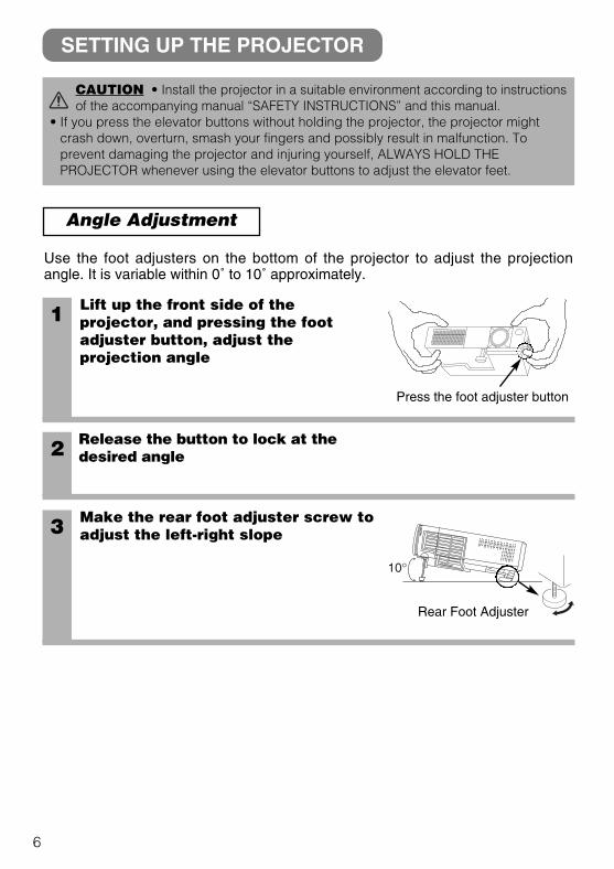
Angle Adjustment
1 Lift up the front side of theprojector, and pressing the footadjuster button, adjust theprojection angle
2 Release the button to lock at thedesired angle
3 Make the rear foot adjuster screw toadjust the left-right slope
Use the foot adjusters on the bottom of the projector to adjust the projectionangle. It is variable within 0˚ to 10˚ approximately.
CAUTION • Install the projector in a suitable environment according to instructionsof the accompanying manual “SAFETY INSTRUCTIONS” and this manual.
• If you press the elevator buttons without holding the projector, the projector mightcrash down, overturn, smash your fingers and possibly result in malfunction. Toprevent damaging the projector and injuring yourself, ALWAYS HOLD THEPROJECTOR whenever using the elevator buttons to adjust the elevator feet.
SETTING UP THE PROJECTOR
Press the foot adjuster button
Rear Foot Adjuster
01CP-S225/X75/Vol1/E/最終 02.10.17 10:24 AM ページ6
7
EN
GL
ISH
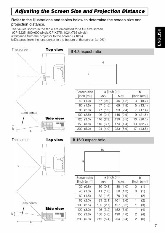
Refer to the illustrations and tables below to determine the screen size andprojection distance.
Adjusting the Screen Size and Projection Distance
Top view
ab
Lens center
The screen
Side view
Top view
a
b
Lens center
The screen
Side view
If 4:3 aspect ratio
If 16:9 aspect ratio
4
3
9
16
The values shown in the table are calculated for a full size screen(CP-S225: 800x600 pixels/CP-X275: 1024x768 pixels).a:Distance from the projector to the screen (±10%)b:Distance from the lens center to the bottom of the screen (±10%)
Screen size[inch (m)]
a [inch (m)] b[inch (cm)]Min. Max.
40 (1.0) 37 (0.9) 46 (1.2) 3 (8.7)60 (1.5) 57 (1.5) 69 (1.8) 5 (13.1)80 (2.0) 77 (1.9) 93 (2.4) 7 (17.4)
100 (2.5) 96 (2.4) 116 (2.9) 9 (21.8)120 (3.0) 116 (2.9) 139 (3.5) 10 (26.1)150 (3.8) 145 (3.7) 174 (4.4) 13 (32.7)
200 (5.0) 194 (4.9) 233 (5.9) 17 (43.5)
Screen size[inch (cm)]
a [inch (m)] b[inch (cm)]Min. Max.
30 (0.8) 30 (0.8) 38 (1.0) 0 (1)40 (1.0) 41 (1.0) 50 (1.3) 0 (1)60 (1.5) 62 (1.6) 76 (1.9) 1 (2)80 (2.0) 83 (2.1) 101 (2.6) 1 (2)
100 (2.5) 105 (2.7) 127 (3.2) 1 (3)120 (3.0) 126 (3.2) 152 (3.9) 1 (4)150 (3.8) 158 (4.0) 190 (4.8) 2 (4)
200 (5.0) 212 (5.4) 254 (6.4) 2 (6)
01CP-S225/X75/Vol1/E/最終 02.10.17 10:24 AM ページ7
8
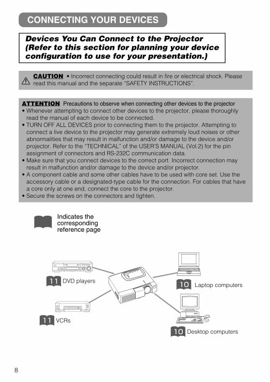
DVD players11
VCRs11
Laptop computers10
Desktop computers10
Indicates thecorrespondingreference page
ATTENTION Precautions to observe when connecting other devices to the projector• Whenever attempting to connect other devices to the projector, please thoroughly
read the manual of each device to be connected.• TURN OFF ALL DEVICES prior to connecting them to the projector. Attempting to
connect a live device to the projector may generate extremely loud noises or otherabnormalities that may result in malfunction and/or damage to the device and/orprojector. Refer to the “TECHNICAL” of the USER’S MANUAL (Vol.2) for the pinassignment of connectors and RS-232C communication data.
• Make sure that you connect devices to the correct port. Incorrect connection mayresult in malfunction and/or damage to the device and/or projector.
• A component cable and some other cables have to be used with core set. Use theaccessory cable or a designated-type cable for the connection. For cables that havea core only at one end, connect the core to the projector.
• Secure the screws on the connectors and tighten.
CONNECTING YOUR DEVICES
Devices You Can Connect to the Projector(Refer to this section for planning your deviceconfiguration to use for your presentation.)
CAUTION • Incorrect connecting could result in fire or electrical shock. Pleaseread this manual and the separate “SAFETY INSTRUCTIONS”.
01CP-S225/X75/Vol1/E/最終 02.10.17 10:24 AM ページ8
9
EN
GL
ISH
Ports and Cables
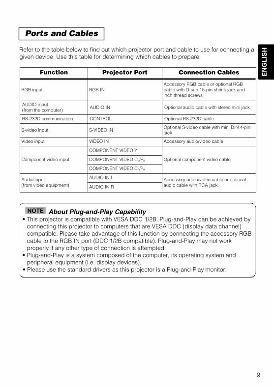
Refer to the table below to find out which projector port and cable to use for connecting agiven device. Use this table for determining which cables to prepare.
About Plug-and-Play Capability• This projector is compatible with VESA DDC 1/2B. Plug-and-Play can be achieved by
connecting this projector to computers that are VESA DDC (display data channel)compatible. Please take advantage of this function by connecting the accessory RGBcable to the RGB IN port (DDC 1/2B compatible). Plug-and-Play may not workproperly if any other type of connection is attempted.
• Plug-and-Play is a system composed of the computer, its operating system andperipheral equipment (i.e. display devices).
• Please use the standard drivers as this projector is a Plug-and-Play monitor.
NOTE
Function Projector Port Connection Cables
RGB input RGB IN Accessory RGB cable or optional RGBcable with D-sub 15-pin shrink jack andinch thread screws
AUDIO input(from the computer)
AUDIO IN Optional audio cable with stereo mini jack
RS-232C communication CONTROL Optional RS-232C cable
S-video input S-VIDEO INOptional S-video cable with mini DIN 4-pinjack
Video input VIDEO IN Accessory audio/video cable
Component video input
COMPONENT VIDEO Y
Optional component video cableCOMPONENT VIDEO CB/PB
COMPONENT VIDEO CR/PR
Audio input(from video equipment)
AUDIO IN L Accessory audio/video cable or optionalaudio cable with RCA jackAUDIO IN R
01CP-S225/X75/Vol1/E/最終 02.10.17 10:24 AM ページ9
10
Laptop computer Desktop computer
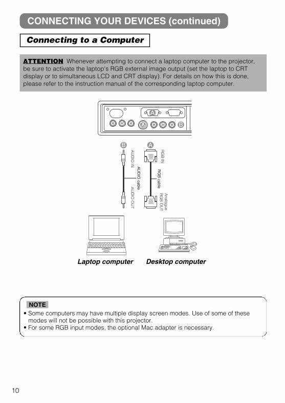
CONNECTING YOUR DEVICES (continued)
Connecting to a Computer
ATTENTION Whenever attempting to connect a laptop computer to the projector,be sure to activate the laptop's RGB external image output (set the laptop to CRTdisplay or to simultaneous LCD and CRT display). For details on how this is done,please refer to the instruction manual of the corresponding laptop computer.
• Some computers may have multiple display screen modes. Use of some of thesemodes will not be possible with this projector.
• For some RGB input modes, the optional Mac adapter is necessary.
NOTE
AA
UD
IO IN
AU
DIO
OU
T
RG
B IN
Analog
ue R
GB
OU
TR
GB
cable
AU
DIO
cable
A
B
B
01CP-S225/X75/Vol1/E/最終 02.10.17 10:24 AM ページ10
11
EN
GL
ISH
DVD player
VCR
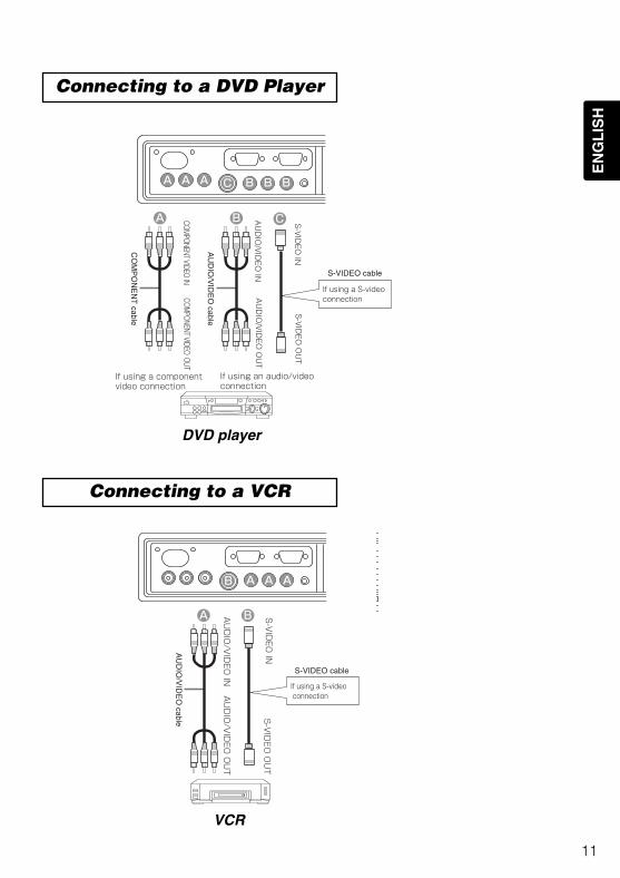
Connecting to a DVD Player
Connecting to a VCR
B CA
If using a component video connection
If using an audio/video connection
COMPONENT VIDEO IN
COMPONENT VIDEO OUT
AU
DIO
/VID
EO
INA
UD
IO/V
IDE
O O
UT
S-V
IDE
O IN
S-V
IDE
O O
UT
If using a S-video connection
CO
MP
ON
EN
T cable
AU
DIO
/VID
EO
cable
S-VIDEO cable
AAA BBBC
B
If using a S-video connection
A AUDIO/VIDEO IN
AUDIO/VIDEO OUT
S-VIDEO IN
S-VIDEO OUT
AU
DIO
/VID
EO
cable
S-VIDEO cable
A A AB
01CP-S225/X75/Vol1/E/最終 02.10.17 10:24 AM ページ11
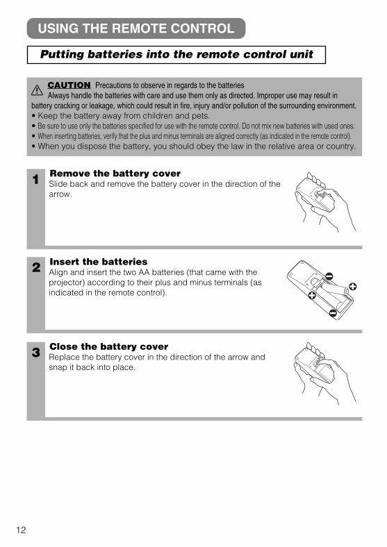
1 Remove the battery coverSlide back and remove the battery cover in the direction of thearrow.
Insert the batteriesAlign and insert the two AA batteries (that came with theprojector) according to their plus and minus terminals (asindicated in the remote control).
Close the battery coverReplace the battery cover in the direction of the arrow andsnap it back into place.
2
3
USING THE REMOTE CONTROL
CAUTION Precautions to observe in regards to the batteriesAlways handle the batteries with care and use them only as directed. Improper use may result in
battery cracking or leakage, which could result in fire, injury and/or pollution of the surrounding environment.• Keep the battery away from children and pets.• Be sure to use only the batteries specified for use with the remote control. Do not mix new batteries with used ones.• When inserting batteries, verify that the plus and minus terminals are aligned correctly (as indicated in the remote control).• When you dispose the battery, you should obey the law in the relative area or country.
12
Putting batteries into the remote control unit
01CP-S225/X75/Vol1/E/最終 02.10.17 10:24 AM ページ12
13
EN
GL
ISH
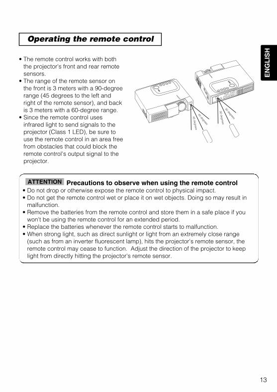
• The remote control works with boththe projector's front and rear remotesensors.
• The range of the remote sensor onthe front is 3 meters with a 90-degreerange (45 degrees to the left andright of the remote sensor), and backis 3 meters with a 60-degree range.
• Since the remote control usesinfrared light to send signals to theprojector (Class 1 LED), be sure touse the remote control in an area freefrom obstacles that could block theremote control's output signal to theprojector.
Precautions to observe when using the remote control• Do not drop or otherwise expose the remote control to physical impact.• Do not get the remote control wet or place it on wet objects. Doing so may result in
malfunction.• Remove the batteries from the remote control and store them in a safe place if you
won't be using the remote control for an extended period. • Replace the batteries whenever the remote control starts to malfunction.• When strong light, such as direct sunlight or light from an extremely close range
(such as from an inverter fluorescent lamp), hits the projector's remote sensor, theremote control may cease to function. Adjust the direction of the projector to keeplight from directly hitting the projector's remote sensor.
ATTENTION
Operating the remote control
30 deg
rees30 degrees
45 deg
rees45 degrees
01CP-S225/X75/Vol1/E/最終 02.10.17 10:24 AM ページ13
14
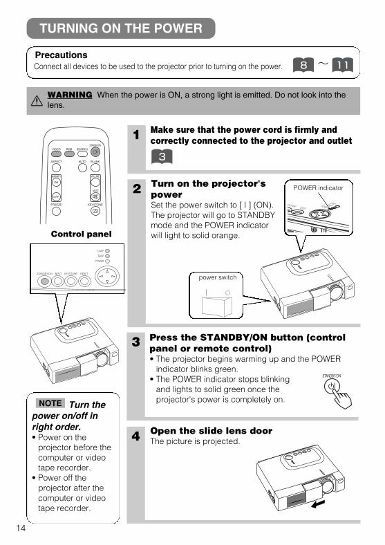
1 Make sure that the power cord is firmly andcorrectly connected to the projector and outlet
2 Turn on the projector'spowerSet the power switch to [ | ] (ON).The projector will go to STANDBYmode and the POWER indicatorwill light to solid orange.
3 Press the STANDBY/ON button (controlpanel or remote control) • The projector begins warming up and the POWER
indicator blinks green.• The POWER indicator stops blinking
and lights to solid green once theprojector's power is completely on.
4 Open the slide lens doorThe picture is projected.
STANDBY/ON INPUT KEYSTONE RESET
LANP
TENP
POWER
KEYSTONE RESET
LANPTENPPOWER
POWER indicator
STANDBY/ON
3VIDEO
ASPECT
MUTE
KEYSTONEFREEZE
OFF
ON
VOLUMEMAGNIFY
AUTO BLANK
RGB SEARCHSTANDBY/ON
TURNING ON THE POWER
Control panel
Precautions Connect all devices to be used to the projector prior to turning on the power. 118 ~
WARNING When the power is ON, a strong light is emitted. Do not look into thelens.
Turn thepower on/off inright order.• Power on the
projector before thecomputer or videotape recorder.
• Power off theprojector after thecomputer or videotape recorder.
NOTE
power switch
01CP-S225/X75/Vol1/E/最終 02.10.17 10:24 AM ページ14
15
EN
GL
ISH
RGB
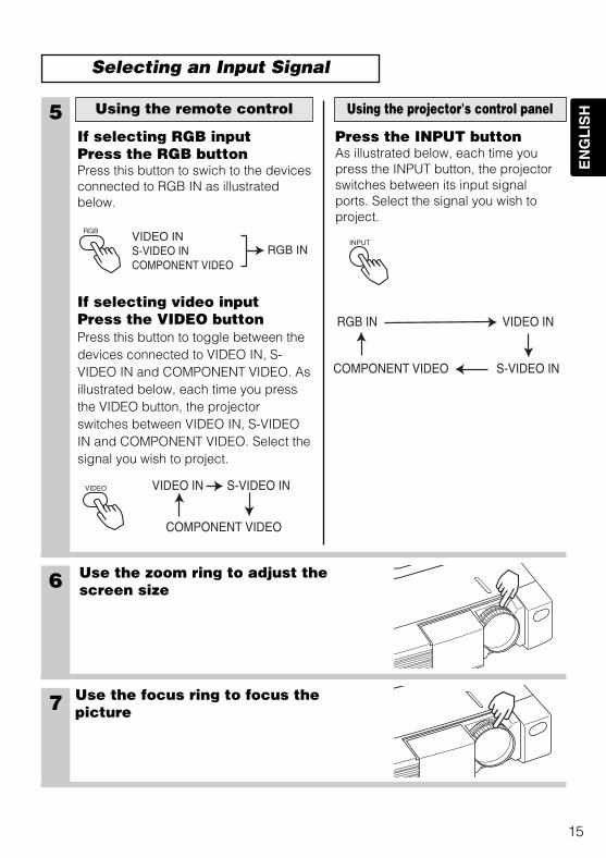
6 Use the zoom ring to adjust thescreen size
7 Use the focus ring to focus thepicture
5If selecting RGB inputPress the RGB buttonPress this button to swich to the devicesconnected to RGB IN as illustratedbelow.
If selecting video inputPress the VIDEO buttonPress this button to toggle between thedevices connected to VIDEO IN, S-VIDEO IN and COMPONENT VIDEO. Asillustrated below, each time you pressthe VIDEO button, the projectorswitches between VIDEO IN, S-VIDEOIN and COMPONENT VIDEO. Select thesignal you wish to project.
Using the remote control
Press the INPUT buttonAs illustrated below, each time youpress the INPUT button, the projectorswitches between its input signalports. Select the signal you wish toproject.
Using the projector's control panel
VIDEO
RGB IN VIDEO IN
S-VIDEO INCOMPONENT VIDEO
VIDEO IN S-VIDEO IN
COMPONENT VIDEO
VIDEO INS-VIDEO INCOMPONENT VIDEO
RGB ININPUT
Selecting an Input Signal
01CP-S225/X75/Vol1/E/最終 02.10.17 10:24 AM ページ15
16
VIDEO
ASPECT
MUTE
KEYSTONEFREEZE
OFF
ON
MENUPOSITION
ENTER
ESC RESET
VOLUMEMAGNIFY
AUTO BLANK
RGB SEARCHSTANDBY/ON
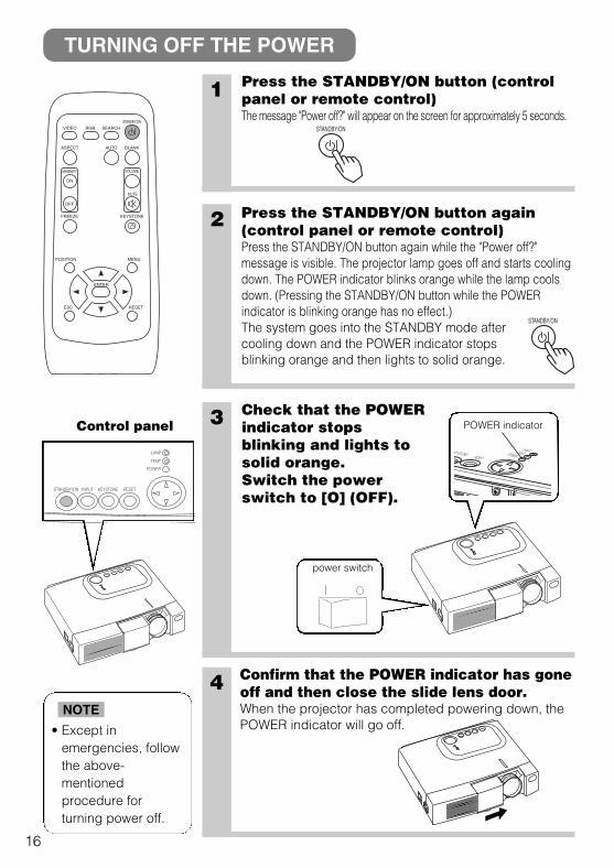
1 Press the STANDBY/ON button (controlpanel or remote control)The message "Power off?" will appear on the screen for approximately 5 seconds.
3 Check that the POWERindicator stopsblinking and lights tosolid orange.Switch the powerswitch to [O] (OFF).
4 Confirm that the POWER indicator has goneoff and then close the slide lens door.When the projector has completed powering down, thePOWER indicator will go off.
STANDBY/ON
TURNING OFF THE POWER
2 Press the STANDBY/ON button again(control panel or remote control)Press the STANDBY/ON button again while the "Power off?"message is visible. The projector lamp goes off and starts coolingdown. The POWER indicator blinks orange while the lamp coolsdown. (Pressing the STANDBY/ON button while the POWERindicator is blinking orange has no effect.)The system goes into the STANDBY mode aftercooling down and the POWER indicator stopsblinking orange and then lights to solid orange.
STANDBY/ON
• Except inemergencies, followthe above-mentionedprocedure forturning power off.
NOTE
STANDBY/ON INPUT KEYSTONE RESET
LANP
TENP
POWER
KEYSTONE RESET
LANPTENPPOWER
POWER indicatorControl panel
power switch
01CP-S225/X75/Vol1/E/最終 02.10.17 10:24 AM ページ16
17
EN
GL
ISH
VIDEO
ASPECT
MUTE
KEYSTONEFREEZE
OFF
ON
MENUPOSITION
ENTER
ESC RESET
VOLUMEMAGNIFY
AUTO BLANK
RGB SEARCHSTANDBY/ON
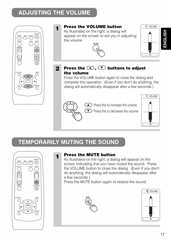
1 Press the VOLUME buttonAs illustrated on the right, a dialog willappear on the screen to aid you in adjustingthe volume.
1 Press the MUTE buttonAs illustrated on the right, a dialog will appear on thescreen indicating that you have muted the sound. Pressthe VOLUME button to close the dialog. (Even if you don'tdo anything, the dialog will automatically disappear aftera few seconds.)Press the MUTE button again to restore the sound.
2 Press the , buttons to adjustthe volumePress the VOLUME button again to close the dialog andcomplete this operation. (Even if you don't do anything, thedialog will automatically disappear after a few seconds.)
Press this to increase the volume
Press this to decrease the volume
VOLUMEVOLUME
MUTEMUTE
VIDEO
ASPECT
MUTE
KEYSTONEFREEZE
OFF
ON
MENUPOSITION
ENTER
ESC RESET
VOLUMEMAGNIFY
AUTO BLANK
RGB SEARCHSTANDBY/ON
16
VOLUME
16
VOLUME
16
VOLUME
ADJUSTING THE VOLUME
TEMPORARILY MUTING THE SOUND
01CP-S225/X75/Vol1/E/最終 02.10.17 10:24 AM ページ17
18
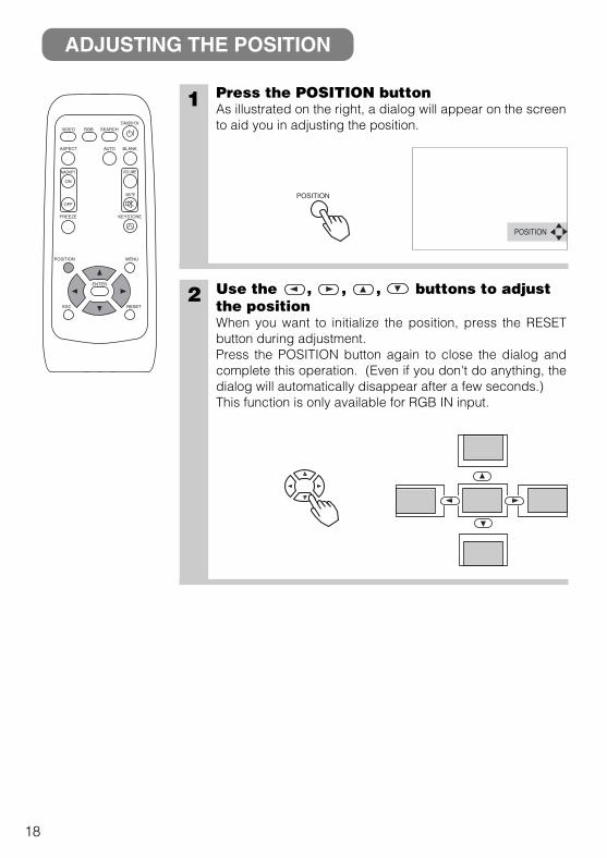
1 Press the POSITION buttonAs illustrated on the right, a dialog will appear on the screento aid you in adjusting the position.
2 Use the , , , buttons to adjustthe positionWhen you want to initialize the position, press the RESETbutton during adjustment.Press the POSITION button again to close the dialog andcomplete this operation. (Even if you don't do anything, thedialog will automatically disappear after a few seconds.)This function is only available for RGB IN input.
ADJUSTING THE POSITION
POSITION
POSITION
VIDEO
ASPECT
MUTE
KEYSTONEFREEZE
OFF
ON
MENUPOSITION
ENTER
ESC RESET
VOLUMEMAGNIFY
AUTO BLANK
RGB SEARCHSTANDBY/ON
01CP-S225/X75/Vol1/E/最終 02.10.17 10:24 AM ページ18
19
EN
GL
ISH
The automatic adjustment operation requires approximately 10 seconds. Also, pleasenote that it may not function correctly with some input signals.
NOTE
1
USING THE AUTOMATIC ADJUSTMENT FEATURE
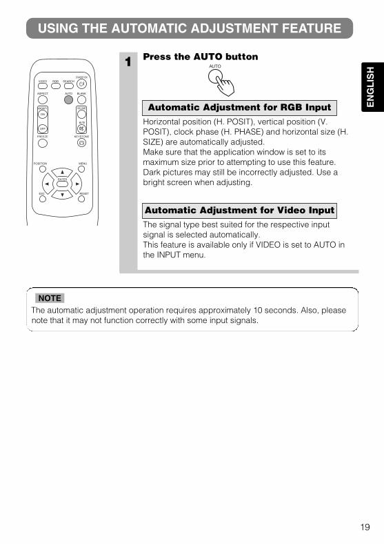
Press the AUTO button
Horizontal position (H. POSIT), vertical position (V.POSIT), clock phase (H. PHASE) and horizontal size (H.SIZE) are automatically adjusted.Make sure that the application window is set to itsmaximum size prior to attempting to use this feature.Dark pictures may still be incorrectly adjusted. Use abright screen when adjusting.
The signal type best suited for the respective inputsignal is selected automatically.This feature is available only if VIDEO is set to AUTO inthe INPUT menu.
Automatic Adjustment for RGB Input
Automatic Adjustment for Video Input
AUTO
VIDEO
ASPECT
MUTE
KEYSTONEFREEZE
OFF
ON
MENUPOSITION
ENTER
ESC RESET
VOLUMEMAGNIFY
AUTO BLANK
RGB SEARCHSTANDBY/ON
01CP-S225/X75/Vol1/E/最終 02.10.17 10:24 AM ページ19
20
• This function may not be work well with some types of input signals.• The adjustable range for correcting keystone distortions will vary with the type of
input signal.
NOTE
CORRECTING KEYSTONE DISTORTIONS
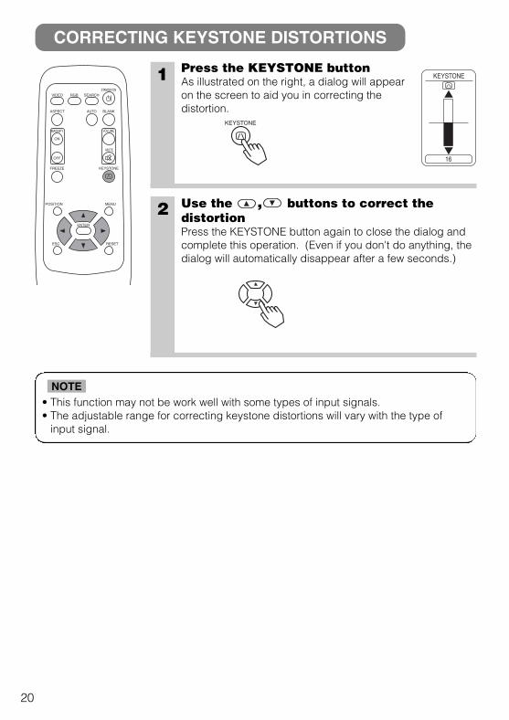
1 Press the KEYSTONE buttonAs illustrated on the right, a dialog will appearon the screen to aid you in correcting thedistortion.
2 Use the , buttons to correct thedistortionPress the KEYSTONE button again to close the dialog andcomplete this operation. (Even if you don't do anything, thedialog will automatically disappear after a few seconds.)
KEYSTONE
VIDEO
ASPECT
MUTE
KEYSTONEFREEZE
OFF
ON
MENUPOSITION
ENTER
ESC RESET
VOLUMEMAGNIFY
AUTO BLANK
RGB SEARCHSTANDBY/ON
16
KEYSTONE
01CP-S225/X75/Vol1/E/最終 02.10.17 10:24 AM ページ20
21
EN
GL
ISH
The projector will automatically exit from MAGNIFY mode if either the INPUT SELECT,AUTO, ASPECT or VIDEO feature is used, or, if there is a change in the input signal's state.
NOTE
• The projector will automatically exit from FREEZE mode if either the POSITION, VOLUME, MUTE, AUTO,BLANK ON/OFF or MENU ON/OFF feature is used, or, if there is a change in the input signal's state.
• If the projector continues projecting the same image for a long time (i.e. you forget to exit FREEZE mode),the image might possibly remain as an afterimage. Do not leave the projector in FREEZE mode for too long.
NOTE
USING THE MAGNIFY FEATURE
FREEZING THE SCREEN
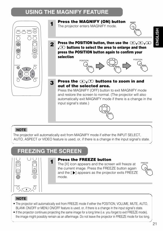
1 Press the MAGNIFY (ON) buttonThe projector enters MAGNIFY mode.
2 Press the POSITION button, then use the , ,, buttons to select the area to enlarge and thenpress the POSITION button again to confirm yourselection
3 Press the , buttons to zoom in andout of the selected area.Press the MAGNIFY (OFF) button to exit MAGNIFY modeand restore the screen to normal. (The projector will alsoautomatically exit MAGNIFY mode if there is a change in theinput signal's state.)
1 Press the FREEZE buttonThe [II] icon appears and the screen will freeze atthe current image. Press the FREEZE button againand the [ ] appears as the projector exits FREEZEmode.
ON
MAGNIFYMAGNIFY
POSITION POSITION
FREEZE
VIDEO
ASPECT
MUTE
KEYSTONEFREEZE
OFF
ON
MENUPOSITION
ENTER
ESC RESET
VOLUMEMAGNIFY
AUTO BLANK
RGB SEARCHSTANDBY/ON
MUTE
KEYSTONEFREEZE
OFF
ON
MENUPOSITION
VOLUMEMAGNIFY
01CP-S225/X75/Vol1/E/最終 02.10.17 10:24 AM ページ21
22
SIGNAL SEARCHING
SELECTING THE ASPECT RATIO
TEMPORARILY BLANKING THE SCREEN
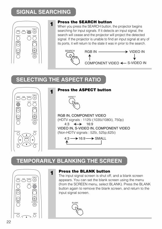
1 Press the SEARCH buttonWhen you press the SEARCH button, the projector beginssearching for input signals. If it detects an input signal, thesearch will cease and the projector will project the detectedsignal. If the projector is unable to find an input signal at any ofits ports, it will return to the state it was in prior to the search.
1 Press the ASPECT button
RGB IN, COMPONENT VIDEO(HDTV signals : 1125i (1035i/1080i), 750p)
VIDEO IN, S-VIDEO IN, COMPONENT VIDEO(Non-HDTV signals : 525i, 525p,625i)
SEARCH
ASPECT
4:3 16:9
4:3 16:9 SMALL
1 Press the BLANK buttonThe input signal screen is shut off, and a blank screenappears. You can set the blank screen using the menu(from the SCREEN menu, select BLANK). Press the BLANKbutton again to remove the blank screen, and return to theinput signal screen.
BLANK
VIDEO
ASPECT
MUTE
KEYSTONEFREEZE
OFF
ON
VOLUMEMAGNIFY
AUTO BLANK
RGB SEARCHSTANDBY/ON
RGB IN VIDEO IN
S-VIDEO INCOMPONENT VIDEO
VIDEO
ASPECT
MUTE
KEYSTONEFREEZE
OFF
ON
MENUPOSITION
ENTER
ESC RESET
VOLUMEMAGNIFY
AUTO BLANK
RGB SEARCHSTANDBY/ON
VIDEO
ASPECT
MUTE
KEYSTONEFREEZE
OFF
ON
MENUPOSITION
VOLUMEMAGNIFY
AUTO BLANK
RGB SEARCHSTANDBY/ON
01CP-S225/X75/Vol1/E/最終 02.10.17 10:24 AM ページ22
23
EN
GL
ISH
USING THE MENU FUNCTIONS
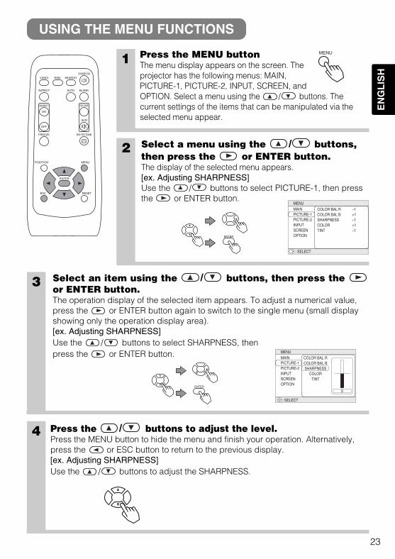
1 Press the MENU buttonThe menu display appears on the screen. Theprojector has the following menus: MAIN,PICTURE-1, PICTURE-2, INPUT, SCREEN, andOPTION. Select a menu using the / buttons. Thecurrent settings of the items that can be manipulated via theselected menu appear.
2 Select a menu using the / buttons,then press the or ENTER button.The display of the selected menu appears.[ex. Adjusting SHARPNESS]Use the / buttons to select PICTURE-1, then pressthe or ENTER button.
: SELECT
MENUMAINPICTURE-1PICTURE-2INPUTSCREENOPTION
COLOR BAL RCOLOR BAL BSHARPNESSCOLORTINT
–1+1–1+1–1
3 Select an item using the / buttons, then press theor ENTER button.The operation display of the selected item appears. To adjust a numerical value,press the or ENTER button again to switch to the single menu (small displayshowing only the operation display area).[ex. Adjusting SHARPNESS]Use the / buttons to select SHARPNESS, thenpress the or ENTER button.
4 Press the / buttons to adjust the level.Press the MENU button to hide the menu and finish your operation. Alternatively,press the or ESC button to return to the previous display.[ex. Adjusting SHARPNESS]Use the / buttons to adjust the SHARPNESS.
ENTER
ENTER
MENU
COLOR BAL RCOLOR BAL BSHARPNESS
COLORTINT
0
MENU
: SELECT
MAINPICTURE-1PICTURE-2INPUTSCREENOPTION
VIDEO
ASPECT
MUTE
KEYSTONEFREEZE
OFF
ON
MENUPOSITION
ENTER
ESC RESET
VOLUMEMAGNIFY
AUTO BLANK
RGB SEARCHSTANDBY/ON
01CP-S225/X75/Vol1/E/最終 02.10.17 10:24 AM ページ23
24
THE LAMP
HIGH VOLTAGEHIGH TEMPERATUREHIGH PRESSURE
Before replacing the lamp, check the serial number of the replacement lamp bulb (sold separately:DT00401 for CP-S225/DT00461 for CP-X275), then contact your local dealer. Before replacing thelamp, turn off the power, and unplug the power cord, then wait at least 45 minutes, in order toensure that the lamp is properly cooled. Removing the lamp bulb while it is still hot could causeburns, or cause the lamp bulb to burst.
The LCD projector uses a glass lamp bulb. It is a mercury lamp with highinternal pressure. High-pressure mercury lamps can break with a loud
bang, or burn out, if jolted or scratched, or through wear over time. Each lamp has adifferent lifetime, and some may burst or burn out soon after you start using them. Inaddition, when the bulb bursts, it is possible for shards of glass to fly into the lamp housing,and for gas containing mercury to escape from the projector’s vent holes.• Handle with care: jolting or scratching could cause the lamp bulb to burst during use.• If the replace lamp indicator (see "Related Messages" (Vol.2 ) and "Regarding the
indicator Lamps" (Vol.2 )) comes on, replace the lamp as soon as possible. Using thelamp for long periods of time, or past the replacement date, could cause it to burst. Donot use old (used) lamps; this is a cause of breakage.
• If the lamp breaks soon after the first time it is used, it is possible that there are electrical problemselsewhere besides the lamp. If this happens, contact your local dealer.
• If the lamp should break (it will make a loud bang when it does), ventilate the room well, and makesure not to breathe the gas that comes out of the projector vents, or get it in your eyes or mouth.
• If the lamp should break (it will make a loud bang when it does), unplug the power cord fromthe outlet, and make sure to request a replacement lamp from your local dealer. Note thatshards of glass could damage the projector’s internals, or cause injury during handling, soplease do not try to clean the projector or replace the lamp yourself.
• Obey local ordinances when disposing of used lamps. In most cases, it is possible to dispose of usedbulbs in the same manner as used glass bottles, but in some cases, bulbs are sorted separately.
• Do not use the projector with the lamp cover removed.
WARNING
7
8
01CP-S225/X75/Vol1/E/最終 02.10.17 10:24 AM ページ24
25
EN
GL
ISH
• The LAMP indicator is also red when the lamp unit reaches high temperature.
Before replacing the lamp, switch power OFF, wait approximately 20 minutes, and switch power
ON again. If the LAMP indicator is still red, replace the lamp.
NOTE
Replacing the lamp
All projector lamps will wear out eventually. If used for long periods of time, the image could becomedarkened, and the color contrast could be impacted as well. We recommend that you replace your lampsearly. If the LAMP indicator turns red, or a message prompts you to replace the lamp when you power upthe projector, the lamp needs to be replaced. (See "Related Messages" (Vol.2 ) and "Regarding theIndicator Lamps" (Vol.2 ) for details.)
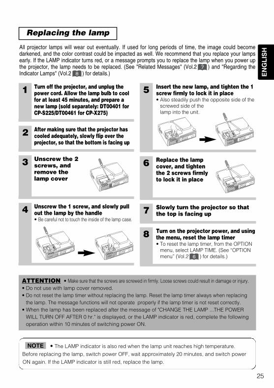
1 Turn off the projector, and unplug thepower cord. Allow the lamp bulb to coolfor at least 45 minutes, and prepare anew lamp (sold separately: DT00401 forCP-S225/DT00461 for CP-X275)
5 Insert the new lamp, and tighten the 1screw firmly to lock it in place• Also steadily push the opposite side of the
screwed side of thelamp into the unit.
6 Replace the lampcover, and tightenthe 2 screws firmlyto lock it in place
7 Slowly turn the projector so thatthe top is facing up
2 After making sure that the projector hascooled adequately, slowly flip over theprojector, so that the bottom is facing up
3 Unscrew the 2screws, andremove thelamp cover
4 Unscrew the 1 screw, and slowly pullout the lamp by the handle• Be careful not to touch the inside of the lamp case.
ATTENTION • Make sure that the screws are screwed in firmly. Loose screws could result in damage or injury.• Do not use with lamp cover removed.• Do not reset the lamp timer without replacing the lamp. Reset the lamp timer always when replacing
the lamp. The message functions will not operate properly if the lamp timer is not reset correctly.• When the lamp has been replaced after the message of "CHANGE THE LAMP ...THE POWER
WILL TURN OFF AFTER 0 hr." is displayed, or the LAMP indicator is red, complete the followingoperation within 10 minutes of switching power ON.
8 Turn on the projector power, and usingthe menu, reset the lamp timer• To reset the lamp timer, from the OPTION
menu, select LAMP TIME. (See “OPTIONmenu” (Vol.2 ) for details.)
8
7
6
01CP-S225/X75/Vol1/E/最終 02.10.17 10:24 AM ページ25
26
THE AIR FILTER
Caring for the air filter
The air filter should be cleaned about every 100 hours. If the LAMP indicator andTEMP indicator blink red simultaneously, or a message prompts you to clean the airfilter when you turn on the unit, the filter needs to be cleaned. (See "RelatedMessages" (Vol.2 ) and "Regarding the Indicator Lamps" (Vol.2 ) for details.)
1 Turn off the projector, and unplug the power cord
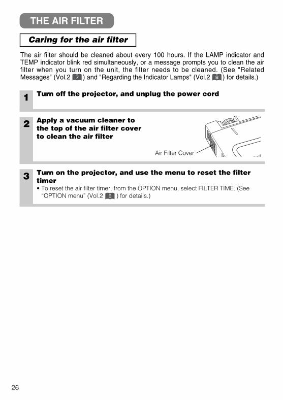
2 Apply a vacuum cleaner tothe top of the air filter coverto clean the air filter
3 Turn on the projector, and use the menu to reset the filtertimer• To reset the air filter timer, from the OPTION menu, select FILTER TIME. (See
“OPTION menu” (Vol.2 ) for details.)
7 8
Air Filter Cover
6
01CP-S225/X75/Vol1/E/最終 02.10.17 10:24 AM ページ26
27
EN
GL
ISH
Replacing the air filter
If the soiling will not come off the air filter, or it becomes damaged, then it needs to bereplaced. Please contact your local dealer, after confirming the model of yourseparately sold replacement air filter. (See "Optional Parts" on Vol.2 .)
1 Turn off the projector, and unplug the power cord. Prepare anew air filter (one specified for your projector)
2 Remove the air filter cover and air filter
4 Turn on the projector power, and using the menu, reset thefilter timer• To reset the filter timer, from the OPTION menu, select FILTER TIME. (See
“OPTION menu” (Vol.2 ) for details.)
3 Insert the new filter, and replace thefilter cover
ATTENTION • Make sure to turn off the power and unplug the power cord before caring forthe unit. Please carefully read "Safety Instructions", in order to care for your projector correctly.• Do not use with air filter cover removed.• If the air filter becomes clogged by dust or the like, internal temperature rises and could cause
malfunction. The power is automatically turned off in order to prevent the unit from overheatinginternally.
10
6
01CP-S225/X75/Vol1/E/最終 02.10.17 10:24 AM ページ27
28
OTHER CARE
Caring for the inside of the projector :In order to ensure the safe use of your projector, please have it cleaned and inspected byyour local dealer about once every 2 years. Never try to care for the inside of the unityourself. Doing so is dangerous.
Caring for the lens :Lightly wipe the lens with a commercially available lens-cleaning wipe. Do not touch thelens directly with your hand.
Caring for the cabinet and remote control transmitter :Wipe lightly with gauze or a soft cloth. If soiling is severe, dip a soft cloth in water or aneutral cleanser diluted in water, and wipe lightly after wringing well. Then, wipe lightlywith a soft, dry cloth.
ATTENTION • Make sure to turn off the power and unplug the power cord before caring forthe unit. Please carefully read "Safety Instructions" in this manual, in order to care for your projectorcorrectly.• Do not use cleaners or chemicals other than those listed above, including benzene and paint
thinner.• Do not use aerosols or sprays.• Do not polish or wipe with hard objects.
01CP-S225/X75/Vol1/E/最終 02.10.17 10:24 AM ページ28
29
EN
GL
ISH
REGULATORY NOTICESREGULATORY NOTICES
WARNING: This equipment has been tested and found to comply with thelimits for a Class B digital device, pursuant to Part 15 of the FCC Rules. Theselimits are designed to provide reasonable protection against harmfulinterference in a residential installation. This equipment generates, uses, andcan radiate radio frequency energy and, if not installed and used in accordancewith the instructions, may cause harmful interference to radio communications.However, there is no guarantee that interference will not occur in a particularinstallation. If this equipment does cause harmful interference to radio ortelevision reception, which can be determined by turning the equipment off andon, the user is encouraged to try to correct the interference by one or more ofthe following measures:- Reorient or relocate the receiving antenna.- Increase the separation between the equipment and receiver.- Connect the equipment into an outlet on a circuit different from that to which
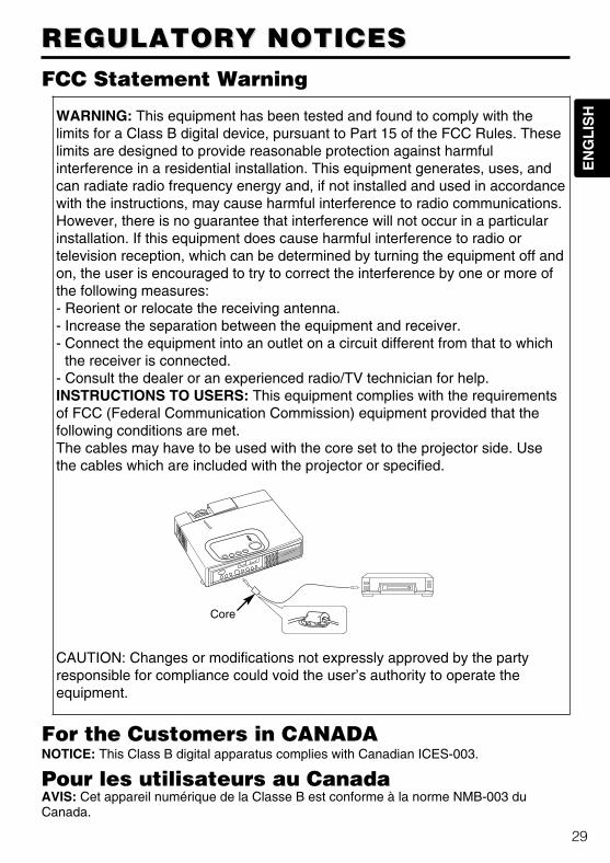
the receiver is connected.- Consult the dealer or an experienced radio/TV technician for help.INSTRUCTIONS TO USERS: This equipment complies with the requirementsof FCC (Federal Communication Commission) equipment provided that thefollowing conditions are met.The cables may have to be used with the core set to the projector side. Usethe cables which are included with the projector or specified.
CAUTION: Changes or modifications not expressly approved by the partyresponsible for compliance could void the user’s authority to operate theequipment.
FCC Statement Warning
For the Customers in CANADANOTICE: This Class B digital apparatus complies with Canadian ICES-003.
Pour les utilisateurs au CanadaAVIS: Cet appareil numérique de la Classe B est conforme à la norme NMB-003 duCanada.
Core
01CP-S225/X75/Vol1/E/最終 02.10.17 10:24 AM ページ29
EN
GL
ISH
1
LCD Projector CP-S225/CP-X275
USER'S MANUAL USER'S MANUAL Vol.2 (Extended)Thank you for purchasing this projector.
• The information in this manual is subject to change without notice.• The manufacturer assumes no responsibility for any errors that may appear in this manual • The reproduction, transmission or use of this document or contents is not permitted without express
written authority.
TRADEMARK ACKNOWLEDGEMENT :• PS/2, VGA and XGA are registered trademarks of the International Business Machines Corporation.• Apple, Mac and ADB are registered trademarks of Apple Computer, Inc.• VESA and SVGA are trademarks of the Video Electronics Standard Association.• Windows is a registered trademark of Microsoft Corporation.• All other trademarks are the property of their respective owners.
NOTE
WARNING • Please read the accompanying manual “SAFETYINSTRUCTIONS” and this “USER'S MANUAL” thoroughly to ensure correct
usage through understanding. After reading, store this instruction manual in asafe place for future reference.
Page
MULTIFUNCTIONAL SETTINGS ........................................................................2
WHAT TO DO WHEN YOU THINK A MACHINE DEFECT HAS OCCURRED ......7SPECIFICATIONS .............................................................................................10WARRANTY AND AFTER-SERVICE................................................................11.......................................................................................
For "TECHNICAL" see the end of this manual.
CONTENTS
MAIN Menu
Item Description
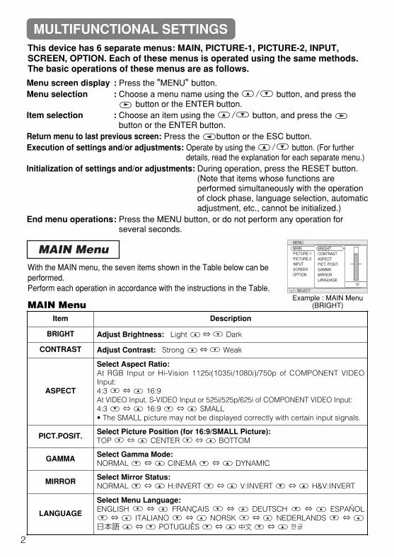
BRIGHT Adjust Brightness: Light ⇔ Dark
CONTRAST Adjust Contrast: Strong ⇔ Weak
ASPECT
Select Aspect Ratio:At RGB Input or Hi-Vision 1125i(1035i/1080i)/750p of COMPONENT VIDEOInput:4:3 ⇔ 16:9At VIDEO Input, S-VIDEO Input or 525i/525p/625i of COMPONENT VIDEO Input:4:3 ⇔ 16:9 ⇔ SMALL• The SMALL picture may not be displayed correctly with certain input signals.
PICT.POSIT. Select Picture Position (for 16:9/SMALL Picture):TOP ⇔ CENTER ⇔ BOTTOM
GAMMA Select Gamma Mode:NORMAL ⇔ CINEMA ⇔ DYNAMIC
MIRROR Select Mirror Status:NORMAL ⇔ H:INVERT ⇔ V:INVERT ⇔ H&V:INVERT
LANGUAGE
Select Menu Language:ENGLISH ⇔ FRANÇAIS ⇔ DEUTSCH ⇔ ESPAÑOL⇔ ITALIANO ⇔ NORSK ⇔ NEDERLANDS ⇔
日本語 ⇔ POTUGUÊS ⇔ 中文 ⇔
MULTIFUNCTIONAL SETTINGSThis device has 6 separate menus: MAIN, PICTURE-1, PICTURE-2, INPUT,SCREEN, OPTION. Each of these menus is operated using the same methods.The basic operations of these menus are as follows.
With the MAIN menu, the seven items shown in the Table below can beperformed.Perform each operation in accordance with the instructions in the Table.
Menu screen display : Press the "MENU" button.Menu selection : Choose a menu name using the / button, and press the
button or the ENTER button.Item selection : Choose an item using the / button, and press the
button or the ENTER button.Return menu to last previous screen: Press the button or the ESC button.Execution of settings and/or adjustments: Operate by using the / button. (For further
details, read the explanation for each separate menu.)Initialization of settings and/or adjustments: During operation, press the RESET button.
(Note that items whose functions areperformed simultaneously with the operationof clock phase, language selection, automaticadjustment, etc., cannot be initialized.)
End menu operations: Press the MENU button, or do not perform any operation forseveral seconds.
MAIN Menu
2
Example : MAIN Menu(BRIGHT)
MENU
: SELECT
MAINPICTURE-1PICTURE-2INPUTSCREENOPTION
BRIGHTCONTRASTASPECTPICT. POSIT.GAMMAMIRRORLANGUAGE
12
EN
GL
ISH
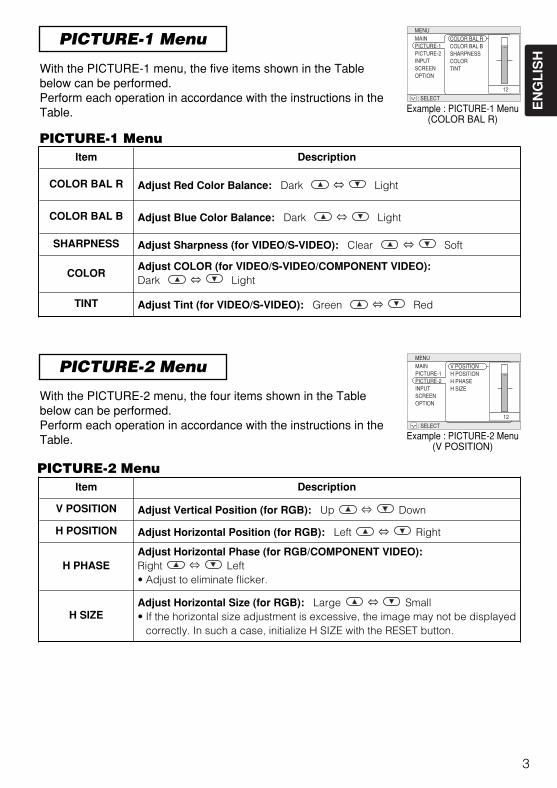
PICTURE-1 Menu
PICTURE-2 Menu
With the PICTURE-1 menu, the five items shown in the Tablebelow can be performed.Perform each operation in accordance with the instructions in theTable.
With the PICTURE-2 menu, the four items shown in the Tablebelow can be performed.Perform each operation in accordance with the instructions in theTable.
Item Description
COLOR BAL R Adjust Red Color Balance: Dark ⇔ Light
COLOR BAL B Adjust Blue Color Balance: Dark ⇔ Light
SHARPNESS Adjust Sharpness (for VIDEO/S-VIDEO): Clear ⇔ Soft
COLORAdjust COLOR (for VIDEO/S-VIDEO/COMPONENT VIDEO):Dark ⇔ Light
TINT Adjust Tint (for VIDEO/S-VIDEO): Green ⇔ Red
PICTURE-1 Menu
Item Description
V POSITION Adjust Vertical Position (for RGB): Up ⇔ Down
H POSITION Adjust Horizontal Position (for RGB): Left ⇔ Right
H PHASEAdjust Horizontal Phase (for RGB/COMPONENT VIDEO):Right ⇔ Left• Adjust to eliminate flicker.
H SIZEAdjust Horizontal Size (for RGB): Large ⇔ Small• If the horizontal size adjustment is excessive, the image may not be displayed
correctly. In such a case, initialize H SIZE with the RESET button.
3
PICTURE-2 Menu
Example : PICTURE-1 Menu(COLOR BAL R)
Example : PICTURE-2 Menu(V POSITION)
MENU
: SELECT
MAINPICTURE-1PICTURE-2INPUTSCREENOPTION
COLOR BAL RCOLOR BAL BSHARPNESSCOLORTINT
12
MENU
: SELECT
MAINPICTURE-1PICTURE-2INPUTSCREENOPTION
V POSITIONH POSITIONH PHASEH SIZE
12
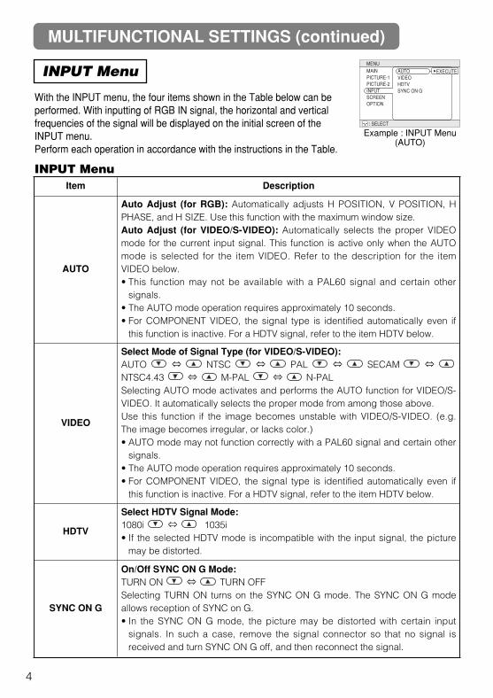
MULTIFUNCTIONAL SETTINGS (continued)
INPUT Menu
With the INPUT menu, the four items shown in the Table below can beperformed. With inputting of RGB IN signal, the horizontal and verticalfrequencies of the signal will be displayed on the initial screen of theINPUT menu.Perform each operation in accordance with the instructions in the Table.
4
Item Description
AUTO
Auto Adjust (for RGB): Automatically adjusts H POSITION, V POSITION, HPHASE, and H SIZE. Use this function with the maximum window size.Auto Adjust (for VIDEO/S-VIDEO): Automatically selects the proper VIDEOmode for the current input signal. This function is active only when the AUTOmode is selected for the item VIDEO. Refer to the description for the itemVIDEO below.• This function may not be available with a PAL60 signal and certain other
signals.• The AUTO mode operation requires approximately 10 seconds.• For COMPONENT VIDEO, the signal type is identified automatically even if
this function is inactive. For a HDTV signal, refer to the item HDTV below.
VIDEO
Select Mode of Signal Type (for VIDEO/S-VIDEO):AUTO ⇔ NTSC ⇔ PAL ⇔ SECAM ⇔NTSC4.43 ⇔ M-PAL ⇔ N-PALSelecting AUTO mode activates and performs the AUTO function for VIDEO/S-VIDEO. It automatically selects the proper mode from among those above. Use this function if the image becomes unstable with VIDEO/S-VIDEO. (e.g.The image becomes irregular, or lacks color.)• AUTO mode may not function correctly with a PAL60 signal and certain other
signals.• The AUTO mode operation requires approximately 10 seconds.• For COMPONENT VIDEO, the signal type is identified automatically even if
this function is inactive. For a HDTV signal, refer to the item HDTV below.
HDTV
Select HDTV Signal Mode:1080i ⇔ 1035i• If the selected HDTV mode is incompatible with the input signal, the picture
may be distorted.
SYNC ON G
On/Off SYNC ON G Mode: TURN ON ⇔ TURN OFFSelecting TURN ON turns on the SYNC ON G mode. The SYNC ON G modeallows reception of SYNC on G.• In the SYNC ON G mode, the picture may be distorted with certain input
signals. In such a case, remove the signal connector so that no signal isreceived and turn SYNC ON G off, and then reconnect the signal.
Example : INPUT Menu(AUTO)
INPUT Menu
MENU
: SELECT
MAINPICTURE-1PICTURE-2INPUTSCREENOPTION
AUTOVIDEOHDTVSYNC ON G
EXECUTE
EN
GL
ISH
SCREEN Menu
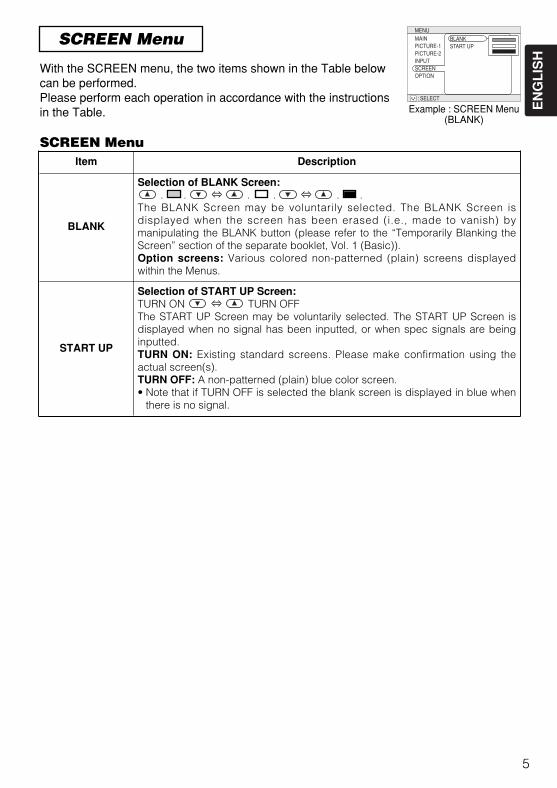
With the SCREEN menu, the two items shown in the Table belowcan be performed.Please perform each operation in accordance with the instructionsin the Table.
5
SCREEN MenuItem Description
BLANK
Selection of BLANK Screen:. . ⇔ . . ⇔ . .
The BLANK Screen may be voluntarily selected. The BLANK Screen isdisplayed when the screen has been erased (i.e., made to vanish) bymanipulating the BLANK button (please refer to the “Temporarily Blanking theScreen” section of the separate booklet, Vol. 1 (Basic)). Option screens: Various colored non-patterned (plain) screens displayedwithin the Menus.
START UP
Selection of START UP Screen:TURN ON ⇔ TURN OFFThe START UP Screen may be voluntarily selected. The START UP Screen isdisplayed when no signal has been inputted, or when spec signals are beinginputted.TURN ON: Existing standard screens. Please make confirmation using theactual screen(s).TURN OFF: A non-patterned (plain) blue color screen.• Note that if TURN OFF is selected the blank screen is displayed in blue when
there is no signal.
Example : SCREEN Menu(BLANK)
MENU
: SELECT
MAINPICTURE-1PICTURE-2INPUTSCREENOPTION
BLANKSTART UP
MULTIFUNCTIONAL SETTINGS (continued)
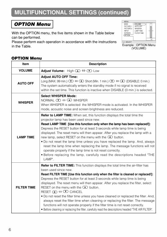
OPTION Menu
With the OPTION menu, the five items shown in the Table belowcan be performed.Please perform each operation in accordance with the instructionsin the Table.
MENU
: SELECT
MAINPICTURE-1PICTURE-2INPUTSCREENOPTION
VOLUMEAUTO OFFWHISPERLAMP TIMEFILTER TIME
12
Item Description
VOLUME Adjust Volume: High ⇔ Low
AUTO OFF
Adjust AUTO OFF Time: Long (MAX. 99 min.) ⇔ Short (Min. 1 min.) ⇔ (DISABLE: 0 min.)The system automatically enters the standby mode if no signal is receivedwithin the set time. This function is inactive when DISABLE (0 min.) is selected.
WHISPER
Select WHISPER Mode: NORMAL ⇔ WHISPERWhen WHISPER is selected the WHISPER mode is activated. In the WHISPERmode, acoustic noise and screen brightness are reduced.
LAMP TIME
Refer to LAMP TIME: When set, this function displays the total time theprojector lamp has been used since new.Reset LAMP TIME [Use this function only when the lamp has been replaced!]:Depress the RESET button for at least 3 seconds while lamp time is beingdisplayed. The reset menu will then appear. After you replace the lamp with anew lamp, select RESET on the menu with the button.• Do not reset the lamp time unless you have replaced the lamp. And, always
reset the lamp time when replacing the lamp. The message functions will notoperate properly if the lamp time is not reset correctly.
• Before replacing the lamp, carefully read the descriptions headed "THELAMP".
FILTER TIME
Refer to FILTER TIME: This function displays the total time the air-filter hasbeen used since new.Reset FILTER TIME [Use this function only when the filter is cleaned or replaced!]:Depress the RESET button for at least 3 seconds while lamp time is beingdisplayed. The reset menu will then appear. After you replace the filter, selectRESET on the menu with the button.RESET ⇔ CANCEL• Do not reset the filter time unless you have cleaned or replaced the filter. And,
always reset the filter time when cleaning or replacing the filter. The messagefunctions will not operate properly if the filter time is not reset correctly.
• Before cleaning or replacing the filter, carefully read the descriptions headed "THE AIR FILTER".
6
Example : OPTION Menu(VOLUME)
OPTION Menu
EN
GL
ISH
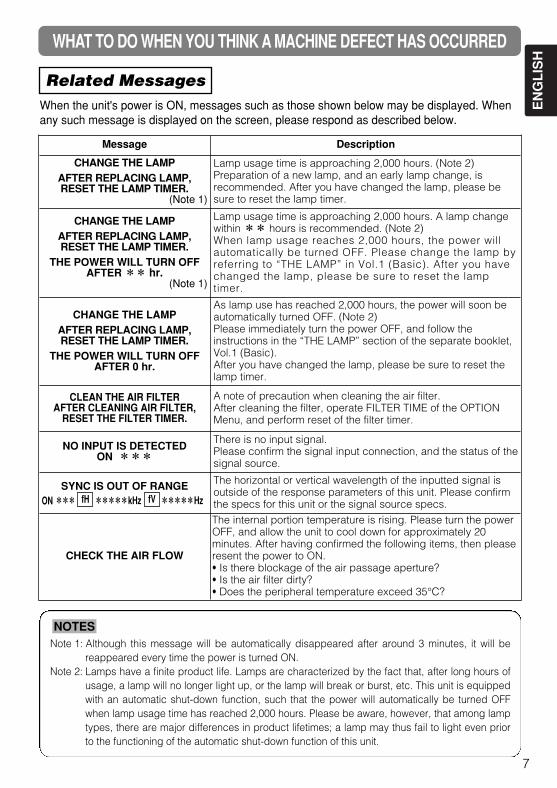
WHAT TO DO WHEN YOU THINK A MACHINE DEFECT HAS OCCURRED
Related MessagesWhen the unit's power is ON, messages such as those shown below may be displayed. Whenany such message is displayed on the screen, please respond as described below.
7
Note 1: Although this message will be automatically disappeared after around 3 minutes, it will bereappeared every time the power is turned ON.
Note 2: Lamps have a finite product life. Lamps are characterized by the fact that, after long hours ofusage, a lamp will no longer light up, or the lamp will break or burst, etc. This unit is equippedwith an automatic shut-down function, such that the power will automatically be turned OFFwhen lamp usage time has reached 2,000 hours. Please be aware, however, that among lamptypes, there are major differences in product lifetimes; a lamp may thus fail to light even priorto the functioning of the automatic shut-down function of this unit.
NOTES
Message Description
CHANGE THE LAMPAFTER REPLACING LAMP, RESET THE LAMP TIMER.
(Note 1)
Lamp usage time is approaching 2,000 hours. (Note 2)Preparation of a new lamp, and an early lamp change, isrecommended. After you have changed the lamp, please besure to reset the lamp timer.
CHANGE THE LAMPAFTER REPLACING LAMP,RESET THE LAMP TIMER.
THE POWER WILL TURN OFFAFTER ** hr.
(Note 1)
Lamp usage time is approaching 2,000 hours. A lamp changewithin ** hours is recommended. (Note 2)When lamp usage reaches 2,000 hours, the power willautomatically be turned OFF. Please change the lamp byreferring to “THE LAMP” in Vol.1 (Basic). After you havechanged the lamp, please be sure to reset the lamptimer.
CHANGE THE LAMPAFTER REPLACING LAMP,RESET THE LAMP TIMER.
THE POWER WILL TURN OFFAFTER 0 hr.
As lamp use has reached 2,000 hours, the power will soon beautomatically turned OFF. (Note 2)Please immediately turn the power OFF, and follow theinstructions in the “THE LAMP” section of the separate booklet,Vol.1 (Basic).After you have changed the lamp, please be sure to reset thelamp timer.
CLEAN THE AIR FILTERAFTER CLEANING AIR FILTER,
RESET THE FILTER TIMER.
A note of precaution when cleaning the air filter.After cleaning the filter, operate FILTER TIME of the OPTIONMenu, and perform reset of the filter timer.
NO INPUT IS DETECTEDON ***
There is no input signal.Please confirm the signal input connection, and the status of thesignal source.
SYNC IS OUT OF RANGEON *** *****kHz *****Hz
The horizontal or vertical wavelength of the inputted signal isoutside of the response parameters of this unit. Please confirmthe specs for this unit or the signal source specs.
CHECK THE AIR FLOW
The internal portion temperature is rising. Please turn the powerOFF, and allow the unit to cool down for approximately 20minutes. After having confirmed the following items, then pleaseresent the power to ON.• Is there blockage of the air passage aperture?• Is the air filter dirty?• Does the peripheral temperature exceed 35°C?
fH fV
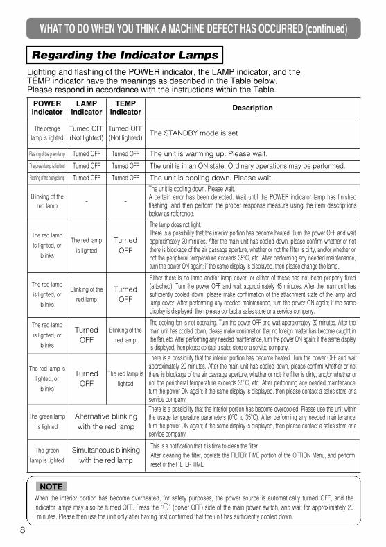
WHAT TO DO WHEN YOU THINK A MACHINE DEFECT HAS OCCURRED (continued)
Regarding the Indicator LampsLighting and flashing of the POWER indicator, the LAMP indicator, and theTEMP indicator have the meanings as described in the Table below.Please respond in accordance with the instructions within the Table.
POWERindicator
LAMPindicator
TEMPindicator Description
The orangelamp is lighted
Turned OFF(Not lighted)
Turned OFF(Not lighted)
The STANDBY mode is set
Flashing of the green lamp Turned OFF Turned OFF The unit is warming up. Please wait.
The green lamp is lighted Turned OFF Turned OFF The unit is in an ON state. Ordinary operations may be performed.
Flashing of the orange lamp Turned OFF Turned OFF The unit is cooling down. Please wait.
Blinking of thered lamp
- -
The unit is cooling down. Please wait.A certain error has been detected. Wait until the POWER indicator lamp has finishedflashing, and then perform the proper response measure using the item descriptionsbelow as reference.
The red lamp
is lighted, or
blinks
The red lamp
is lighted
TurnedOFF
The lamp does not light.There is a possibility that the interior portion has become heated. Turn the power OFF and waitapproximately 20 minutes. After the main unit has cooled down, please confirm whether or notthere is blockage of the air passage aperture, whether or not the filter is dirty, and/or whether ornot the peripheral temperature exceeds 35°C, etc. After performing any needed maintenance,turn the power ON again; if the same display is displayed, then please change the lamp.
The red lamp
is lighted, or
blinks
Blinking of the
red lamp
TurnedOFF
Either there is no lamp and/or lamp cover, or either of these has not been properly fixed(attached). Turn the power OFF and wait approximately 45 minutes. After the main unit hassufficiently cooled down, please make confirmation of the attachment state of the lamp andlamp cover. After performing any needed maintenance, turn the power ON again; if the samedisplay is displayed, then please contact a sales store or a service company.
The red lamp
is lighted, or
blinks
TurnedOFF
Blinking of the
red lamp
The cooling fan is not operating. Turn the power OFF and wait approximately 20 minutes. After themain unit has cooled down, please make confirmation that no foreign matter has become caught inthe fan, etc. After performing any needed maintenance, turn the power ON again; if the same displayis displayed, then please contact a sales store or a service company.
The red lamp is
lighted, or
blinks
TurnedOFF
The red lamp is
lighted
There is a possibility that the interior portion has become heated. Turn the power OFF and waitapproximately 20 minutes. After the main unit has cooled down, please confirm whether or notthere is blockage of the air passage aperture, whether or not the filter is dirty, and/or whether ornot the peripheral temperature exceeds 35°C, etc. After performing any needed maintenance,turn the power ON again; if the same display is displayed, then please contact a sales store or aservice company.
The green lamp
is lighted
Alternative blinkingwith the red lamp
There is a possibility that the interior portion has become overcooled. Please use the unit withinthe usage temperature parameters (0°C to 35°C). After performing any needed maintenance,turn the power ON again; if the same display is displayed, then please contact a sales store or aservice company.
The green
lamp is lighted
Simultaneous blinkingwith the red lamp
This is a notification that it is time to clean the filter.After cleaning the filter, operate the FILTER TIME portion of the OPTION Menu, and performreset of the FILTER TIME.
When the interior portion has become overheated, for safety purposes, the power source is automatically turned OFF, and theindicator lamps may also be turned OFF. Press the “” (power OFF) side of the main power switch, and wait for approximately 20minutes. Please then use the unit only after having first confirmed that the unit has sufficiently cooled down.
NOTE
8
EN
GL
ISH
9
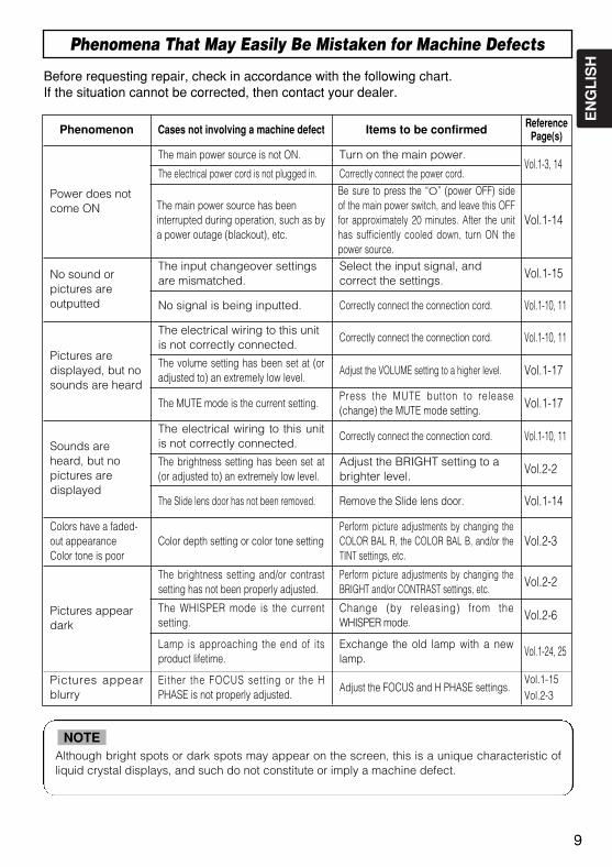
Phenomena That May Easily Be Mistaken for Machine Defects
Before requesting repair, check in accordance with the following chart.If the situation cannot be corrected, then contact your dealer.
Although bright spots or dark spots may appear on the screen, this is a unique characteristic ofliquid crystal displays, and such do not constitute or imply a machine defect.
NOTE
Phenomenon Cases not involving a machine defect Items to be confirmed ReferencePage(s)
Power does notcome ON
The main power source is not ON. Turn on the main power.Vol.1-3, 14
The electrical power cord is not plugged in. Correctly connect the power cord.
The main power source has beeninterrupted during operation, such as bya power outage (blackout), etc.
Be sure to press the “O” (power OFF) sideof the main power switch, and leave this OFFfor approximately 20 minutes. After the unithas sufficiently cooled down, turn ON thepower source.
Vol.1-14
No sound orpictures areoutputted
The input changeover settingsare mismatched.
Select the input signal, andcorrect the settings. Vol.1-15
No signal is being inputted. Correctly connect the connection cord. Vol.1-10, 11
Pictures aredisplayed, but nosounds are heard
The electrical wiring to this unitis not correctly connected.
Correctly connect the connection cord. Vol.1-10, 11
The volume setting has been set at (oradjusted to) an extremely low level.
Adjust the VOLUME setting to a higher level. Vol.1-17
The MUTE mode is the current setting.Press the MUTE button to release(change) the MUTE mode setting. Vol.1-17
Sounds areheard, but nopictures aredisplayed
The electrical wiring to this unitis not correctly connected.
Correctly connect the connection cord. Vol.1-10, 11
The brightness setting has been set at(or adjusted to) an extremely low level.
Adjust the BRIGHT setting to abrighter level. Vol.2-2
The Slide lens door has not been removed. Remove the Slide lens door. Vol.1-14
Colors have a faded-out appearanceColor tone is poor
Color depth setting or color tone settingPerform picture adjustments by changing theCOLOR BAL R, the COLOR BAL B, and/or theTINT settings, etc.
Vol.2-3
Pictures appeardark
The brightness setting and/or contrastsetting has not been properly adjusted.
Perform picture adjustments by changing theBRIGHT and/or CONTRAST settings, etc. Vol.2-2
The WHISPER mode is the currentsetting.
Change (by releasing) from theWHISPER mode. Vol.2-6
Lamp is approaching the end of itsproduct lifetime.
Exchange the old lamp with a newlamp. Vol.1-24, 25
Pictures appearblurry
Either the FOCUS setting or the HPHASE is not properly adjusted.
Adjust the FOCUS and H PHASE settings.Vol.1-15Vol.2-3
9
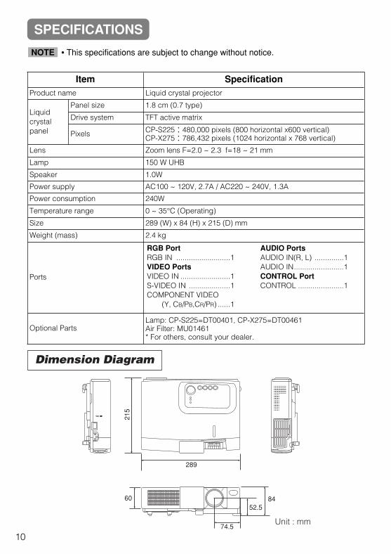
Dimension Diagram
Unit : mm
289
8452.5
74.5
215
60
Item SpecificationProduct name Liquid crystal projector
Liquidcrystalpanel
Panel size 1.8 cm (0.7 type)
Drive system TFT active matrix
Pixels CP-S225:480,000 pixels (800 horizontal x600 vertical)CP-X275:786,432 pixels (1024 horizontal x 768 vertical)
Lens Zoom lens F=2.0 ~ 2.3 f=18 ~ 21 mm
Lamp 150 W UHB
Speaker 1.0W
Power supply AC100 ~ 120V, 2.7A / AC220 ~ 240V, 1.3A
Power consumption 240W
Temperature range 0 ~ 35°C (Operating)
Size 289 (W) x 84 (H) x 215 (D) mm
Weight (mass) 2.4 kg
Ports
Optional PartsLamp: CP-S225=DT00401, CP-X275=DT00461Air Filter: MU01461* For others, consult your dealer.
RGB PortRGB IN ..........................1VIDEO PortsVIDEO IN ........................1S-VIDEO IN ....................1COMPONENT VIDEO
(Y, CB/PB,CR/PR) ......1
AUDIO PortsAUDIO IN(R, L) ..............1AUDIO IN........................1CONTROL PortCONTROL ......................1
• This specifications are subject to change without notice.NOTE
SPECIFICATIONS
10

EN
GL
ISH
If a problem occurs with the equipment, first refer to the “WHAT TO DO WHEN YOUTHINK A MACHINE DEFECT HAS OCCURRED” section and run through the suggestedchecks. If this does not resolve the problem contact your dealer or service company. Theywill tell you what warranty condition is applied.
WARRANTY AND AFTER-SERVICE
11
7

1
TECHNICALTECHNICAL
TEC
HN
ICA
L
SIGNAL CONNECTOR PIN ASSIGNMENTRGB IN [1]/[2]RGB OUT
D-sub 15-pin Shrink Mini Din 4-pin
S-VIDEO
Mini Din 4-pin
Pin No Signal
1
Color:0.286Vp-p (NTSC, burst signal),75Ω terminator0.3Vp-p (PAL/SECAM, burst signal),75Ω terminator
2 Brightness:1.0Vp-p, 75Ω terminator
3 Ground
4 Ground
Pin No Signal Pin No Signal
1 Video input Red 9 -
2 Video input Green 10 Ground
3 Video input Blue 11 -
4 -
12
RGB IN [1]: SDA (DDC)
5 Ground RGB IN [2]: -
6 Ground Red RGB OUT : -
7 Ground Green 13 H. sync./ Composite sync.
8 Ground Blue 14 Vertical sync
15
RGB IN [1]: SCL (DDC)
RGB IN [2]: -
RGB OUT : -
signal Terminal Specification
RGB signalinput RGB IN
Video: Analog 0.7Vp-p, 75Ω terminator (positive)H/V. sync.: TTL level (positive/negative)Composite sync.: TTL levelD-sub 15-pin shrink jack
AUDIO input(from thecomputer)
AUDIO IN 200mVrms, 50 kΩ (max. 3.0Vp-p) Stereo mini jack
Video signalinput
VIDEO IN 1.0Vp-p, 75Ω terminator, RCA jack
S-VIDEO IN
Brightness signal: 1.0Vp-p, 75Ω terminatorColor signal: 0.286Vp-p (NTSC, burst signal),75Ω terminator
0.300Vp-p (PAL/SECAM, burst signal),75Ω terminator Mini DIN 4-pin jack
COMPONENTVIDEO
Y 1.0 Vp-p, 75 Ω Terminator (Positive)
CB/PB 0.7 Vp-p, 75 Ω Terminator (Positive)
CR/PR 0.7 Vp-p, 75 Ω Terminator (Positive)
Audio input(from videoequipment)
AUDIO IN(R、L)200mVrms, 50 kΩ (max. 3.0Vp-p)RCA jack
2
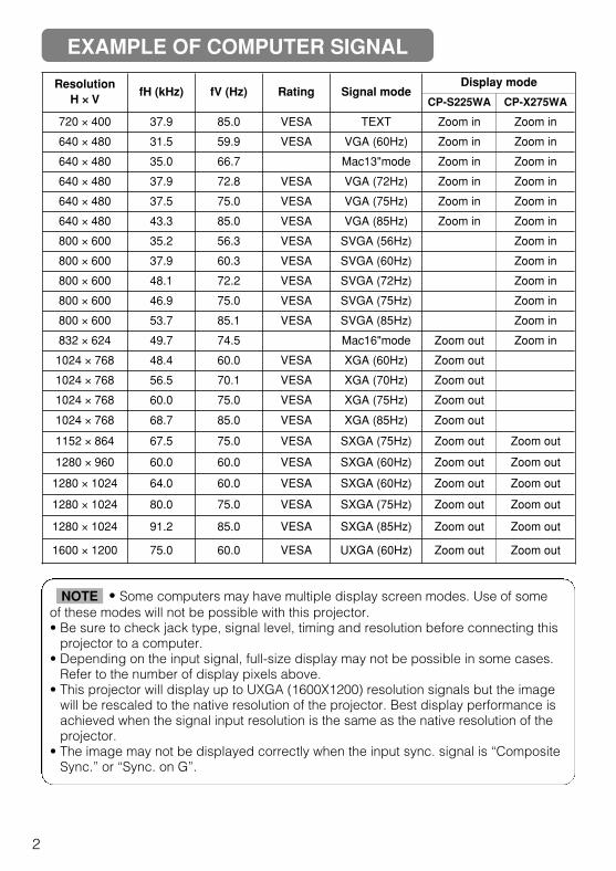
Resolution H ×× V
fH (kHz) fV (Hz) Rating Signal modeDisplay mode
CP-S225WA CP-X275WA
720 × 400 37.9 85.0 VESA TEXT Zoom in Zoom in
640 × 480 31.5 59.9 VESA VGA (60Hz) Zoom in Zoom in
640 × 480 35.0 66.7 Mac13"mode Zoom in Zoom in
640 × 480 37.9 72.8 VESA VGA (72Hz) Zoom in Zoom in
640 × 480 37.5 75.0 VESA VGA (75Hz) Zoom in Zoom in
640 × 480 43.3 85.0 VESA VGA (85Hz) Zoom in Zoom in
800 × 600 35.2 56.3 VESA SVGA (56Hz) Zoom in
800 × 600 37.9 60.3 VESA SVGA (60Hz) Zoom in
800 × 600 48.1 72.2 VESA SVGA (72Hz) Zoom in
800 × 600 46.9 75.0 VESA SVGA (75Hz) Zoom in
800 × 600 53.7 85.1 VESA SVGA (85Hz) Zoom in
832 × 624 49.7 74.5 Mac16"mode Zoom out Zoom in
1024 × 768 48.4 60.0 VESA XGA (60Hz) Zoom out
1024 × 768 56.5 70.1 VESA XGA (70Hz) Zoom out
1024 × 768 60.0 75.0 VESA XGA (75Hz) Zoom out
1024 × 768 68.7 85.0 VESA XGA (85Hz) Zoom out
1152 × 864 67.5 75.0 VESA SXGA (75Hz) Zoom out Zoom out
1280 × 960 60.0 60.0 VESA SXGA (60Hz) Zoom out Zoom out
1280 × 1024 64.0 60.0 VESA SXGA (60Hz) Zoom out Zoom out
1280 × 1024 80.0 75.0 VESA SXGA (75Hz) Zoom out Zoom out
1280 × 1024 91.2 85.0 VESA SXGA (85Hz) Zoom out Zoom out
1600 × 1200 75.0 60.0 VESA UXGA (60Hz) Zoom out Zoom out
EXAMPLE OF COMPUTER SIGNAL
• Some computers may have multiple display screen modes. Use of someof these modes will not be possible with this projector.• Be sure to check jack type, signal level, timing and resolution before connecting this
projector to a computer.• Depending on the input signal, full-size display may not be possible in some cases.
Refer to the number of display pixels above.• This projector will display up to UXGA (1600X1200) resolution signals but the image
will be rescaled to the native resolution of the projector. Best display performance isachieved when the signal input resolution is the same as the native resolution of theprojector.
• The image may not be displayed correctly when the input sync. signal is “CompositeSync.” or “Sync. on G”.
NOTE
3
TEC
HN
ICA
L
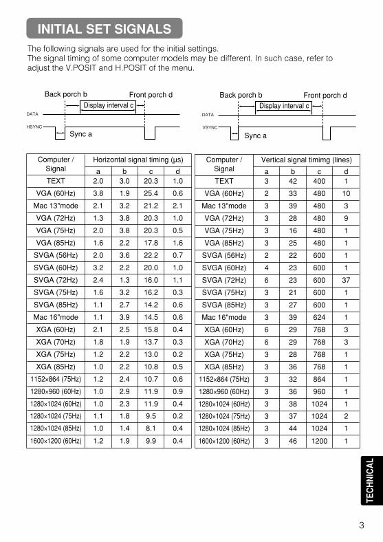
The following signals are used for the initial settings.The signal timing of some computer models may be different. In such case, refer toadjust the V.POSIT and H.POSIT of the menu.
DATA
HSYNC
DATA
VSYNC
Display interval c
Back porch b
Sync a
Front porch d
Display interval c
Back porch b
Sync a
Front porch d
Computer /Signal
Horizontal signal timing (µs)
a b c dTEXT 2.0 3.0 20.3 1.0
VGA (60Hz) 3.8 1.9 25.4 0.6
Mac 13"mode 2.1 3.2 21.2 2.1
VGA (72Hz) 1.3 3.8 20.3 1.0
VGA (75Hz) 2.0 3.8 20.3 0.5
VGA (85Hz) 1.6 2.2 17.8 1.6
SVGA (56Hz) 2.0 3.6 22.2 0.7
SVGA (60Hz) 3.2 2.2 20.0 1.0
SVGA (72Hz) 2.4 1.3 16.0 1.1
SVGA (75Hz) 1.6 3.2 16.2 0.3
SVGA (85Hz) 1.1 2.7 14.2 0.6
Mac 16"mode 1.1 3.9 14.5 0.6
XGA (60Hz) 2.1 2.5 15.8 0.4
XGA (70Hz) 1.8 1.9 13.7 0.3
XGA (75Hz) 1.2 2.2 13.0 0.2
XGA (85Hz) 1.0 2.2 10.8 0.5
1152×864 (75Hz) 1.2 2.4 10.7 0.6
1280×960 (60Hz) 1.0 2.9 11.9 0.9
1280×1024 (60Hz) 1.0 2.3 11.9 0.4
1280×1024 (75Hz) 1.1 1.8 9.5 0.2
1280×1024 (85Hz) 1.0 1.4 8.1 0.4
1600×1200 (60Hz) 1.2 1.9 9.9 0.4
Computer /Signal
Vertical signal timimg (lines)
a b c dTEXT 3 42 400 1
VGA (60Hz) 2 33 480 10
Mac 13"mode 3 39 480 3
VGA (72Hz) 3 28 480 9
VGA (75Hz) 3 16 480 1
VGA (85Hz) 3 25 480 1
SVGA (56Hz) 2 22 600 1
SVGA (60Hz) 4 23 600 1
SVGA (72Hz) 6 23 600 37
SVGA (75Hz) 3 21 600 1
SVGA (85Hz) 3 27 600 1
Mac 16"mode 3 39 624 1
XGA (60Hz) 6 29 768 3
XGA (70Hz) 6 29 768 3
XGA (75Hz) 3 28 768 1
XGA (85Hz) 3 36 768 1
1152×864 (75Hz) 3 32 864 1
1280×960 (60Hz) 3 36 960 1
1280×1024 (60Hz) 3 38 1024 1
1280×1024 (75Hz) 3 37 1024 2
1280×1024 (85Hz) 3 44 1024 1
1600×1200 (60Hz) 3 46 1200 1
INITIAL SET SIGNALS
4
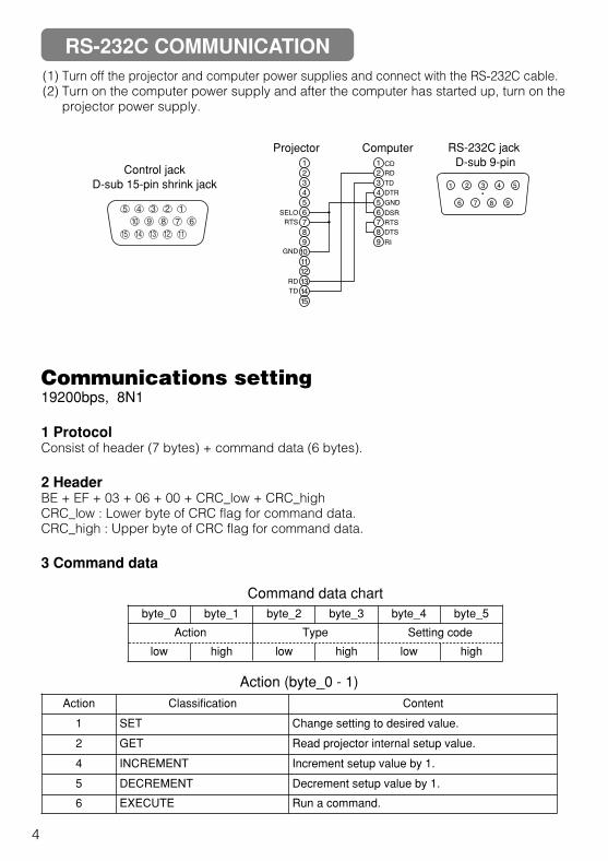
(1) Turn off the projector and computer power supplies and connect with the RS-232C cable.(2) Turn on the computer power supply and after the computer has started up, turn on the
projector power supply.
Control jackD-sub 15-pin shrink jack
1
2
3
4
5
6
7
8
9
10
11
12
13
14
15
RD
TD
GND
SELO
RTS
1
2
3
4
5
6
7
8
9
CD
RD
TD
DTR
GND
DSR
RTS
DTS
RI
1 2 3 4 5
6 7 8 9
RS-232C jack D-sub 9-pin
Projector Computer
Communications setting19200bps, 8N1
1 ProtocolConsist of header (7 bytes) + command data (6 bytes).
2 HeaderBE + EF + 03 + 06 + 00 + CRC_low + CRC_highCRC_low : Lower byte of CRC flag for command data.CRC_high : Upper byte of CRC flag for command data.
3 Command data
byte_0 byte_1 byte_2 byte_3 byte_4 byte_5
Action Type Setting code
low high low high low high
Command data chart
Action (byte_0 - 1)Action Classification Content
1 SET Change setting to desired value.
2 GET Read projector internal setup value.
4 INCREMENT Increment setup value by 1.
5 DECREMENT Decrement setup value by 1.
6 EXECUTE Run a command.
RS-232C COMMUNICATION

TEC
HN
ICA
L
5
Requesting projector status (Get command)(1) Send the request code Header + Command data (‘02H’+‘00H’+ type (2 bytes)
+‘00H’+‘00H’) from the computer to the projector.(2) The projector returns the response code ‘1DH’+ data (2 bytes) to the computer.
Changing the projector settings (Set command)(1) Send the setting code Header + Command data (‘01H’+‘00H’+ type (2 bytes) +
setting code (2 bytes)) from the computer to the projector.(2) The projector changes the setting based on the above setting code.(3) The projector returns the response code ‘06H’ to the computer.
Using the projector default settings (Reset Command)(1) The computer sends the default setting code Header + Command data (‘06H’+‘00H’+
type (2 bytes) +‘00H’+‘00H’) to the projector.(2) The projector changes the specified setting to the default value.(3) The projector returns the response code ‘06H’ to the computer.
Increasing the projector setting value (Increment command)(1) The computer sends the increment code Header + Command data (‘04H’+‘00H’+
type (2 bytes) +‘00H’+‘00H’) to the projector.(2) The projector in creases the setting value on the above setting code.(3) The projector returns the response code ‘06H’ to the computer.
Decreasing the projector setting value (Decrement command)(1) The computer sends the decrement code Header + Command data (‘05H’+‘00H’+
type (2 bytes) +‘00H’ + ‘00H’) to the projector.(2) The projector decreases the setting value on the above setting code.(3) The projector returns the response code ‘06H’ to the computer.
When a command sent by the projector cannot be understood by the computerWhen the command sent by the projector cannot be understood, the error command ‘15H’ isreturned by the computer. Some times, the projector ignores RS-232C commands duringother works. If the error command ‘15H’ is returned, please send the same command again.
When data sent by the projector cannot be practiceWhen the command sent by the projector cannot be practiced, the the error code ‘1cH’+‘xxxxH’ is returned.When the data length is greater than indicated by the data length code, the projector willignore the excess data code.Conversely, when the data length is shorter than indicated by the data length code, anerror code will be returned to the projector.
• Operation cannot be guaranteed when the projector receives anundefined command or data.• Provide an interval of at least 40ms between the response code and any other code.• The projector outputs test data when the power supply is switched ON, and when the
lamp is lit. Ignore this data.• Commands are not accepted during warm-up.
NOTE
6
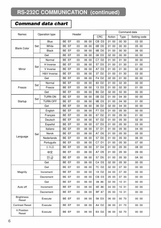
Command data chart
Names Operation type HeaderCommand data
CRC Action Type Setting code
Blank ColorSet
Blue BE EF 03 06 00 CB D3 01 00 00 30 03 00
White BE EF 03 06 00 6B D0 01 00 00 30 05 00
Black BE EF 03 06 00 9B D0 01 00 00 30 06 00
Get BE EF 03 06 00 08 D3 02 00 00 30 00 00
MirrorSet
Normal BE EF 03 06 00 C7 D2 01 00 01 30 00 00
H Inverse BE EF 03 06 00 57 D3 01 00 01 30 01 00
V lnverse BE EF 03 06 00 A7 D3 01 00 01 30 02 00
H&V Inverse BE EF 03 06 00 37 D2 01 00 01 30 03 00
Get BE EF 03 06 00 F4 D2 02 00 01 30 00 00
FreezeSet
Normal BE EF 03 06 00 83 D2 01 00 02 30 00 00
Freeze BE EF 03 06 00 13 D3 01 00 02 30 01 00
Get BE EF 03 06 00 B0 D2 02 00 02 30 00 00
StartupSet
TURN ON BE EF 03 06 00 0B D2 01 00 04 30 00 00
TURN OFF BE EF 03 06 00 9B D3 01 00 04 30 01 00
Get BE EF 03 06 00 38 D2 02 00 04 30 00 00
LanguageSet
English BE EF 03 06 00 F7 D3 01 00 05 30 00 00
Français BE EF 03 06 00 67 D2 01 00 05 30 01 00
Deutsch BE EF 03 06 00 97 D2 01 00 05 30 02 00
Español BE EF 03 06 00 07 D3 01 00 05 30 03 00
Italiano BE EF 03 06 00 37 D1 01 00 05 30 04 00
Norsk BE EF 03 06 00 A7 D0 01 00 05 30 05 00
Nederlands BE EF 03 06 00 57 D0 01 00 05 30 06 00
Português BE EF 03 06 00 C7 D1 01 00 05 30 07 00
日本語 BE EF 03 06 00 37 D4 01 00 05 30 08 00
中文 BE EF 03 06 00 A7 D5 01 00 05 30 09 00
BE EF 03 06 00 57 D5 01 00 05 30 0A 00
Get BE EF 03 06 00 C4 D3 02 00 05 30 00 00
Magnify
Get BE EF 03 06 00 7C D2 02 00 07 30 00 00
Increment BE EF 03 06 00 1A D2 04 00 07 30 00 00
Decrement BE EF 03 06 00 CB D3 05 00 07 30 00 00
Auto off
Get BE EF 03 06 00 08 86 02 00 10 31 00 00
Increment BE EF 03 06 00 6E 86 04 00 10 31 00 00
Decrement BE EF 03 06 00 BF 87 05 00 10 31 00 00
BrightnessReset
Execute BE EF 03 06 00 58 D3 06 00 00 70 00 00
Contrast Reset Execute BE EF 03 06 00 A4 D2 06 00 01 70 00 00
V.PositionReset
Execute BE EF 03 06 00 E0 D2 06 00 02 70 00 00
RS-232C COMMUNICATION (continued)
TEC
HN
ICA
L
7
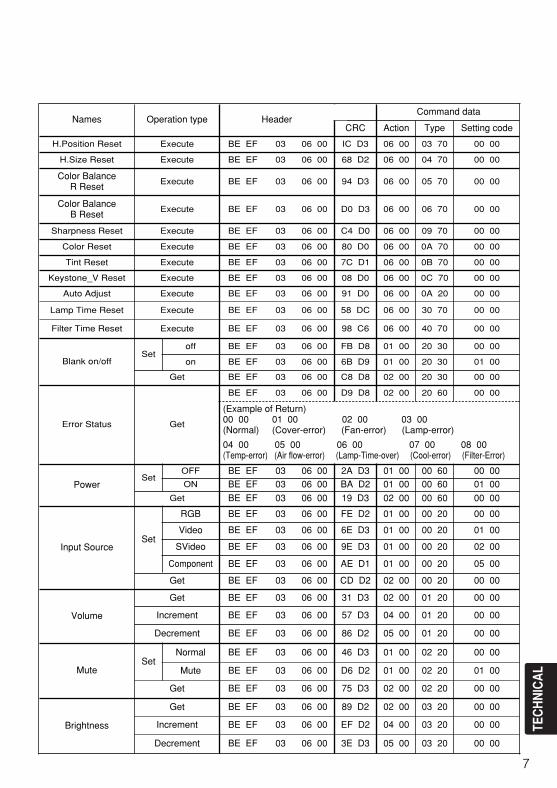
Names Operation type HeaderCommand data
CRC Action Type Setting code
H.Position Reset Execute BE EF 03 06 00 IC D3 06 00 03 70 00 00
H.Size Reset Execute BE EF 03 06 00 68 D2 06 00 04 70 00 00
Color Balance R Reset
Execute BE EF 03 06 00 94 D3 06 00 05 70 00 00
Color Balance B Reset
Execute BE EF 03 06 00 D0 D3 06 00 06 70 00 00
Sharpness Reset Execute BE EF 03 06 00 C4 D0 06 00 09 70 00 00
Color Reset Execute BE EF 03 06 00 80 D0 06 00 0A 70 00 00
Tint Reset Execute BE EF 03 06 00 7C D1 06 00 0B 70 00 00
Keystone_V Reset Execute BE EF 03 06 00 08 D0 06 00 0C 70 00 00
Auto Adjust Execute BE EF 03 06 00 91 D0 06 00 0A 20 00 00
Lamp Time Reset Execute BE EF 03 06 00 58 DC 06 00 30 70 00 00
Filter Time Reset Execute BE EF 03 06 00 98 C6 06 00 40 70 00 00
Blank on/offSet
off BE EF 03 06 00 FB D8 01 00 20 30 00 00
on BE EF 03 06 00 6B D9 01 00 20 30 01 00
Get BE EF 03 06 00 C8 D8 02 00 20 30 00 00
Error Status Get
BE EF 03 06 00 D9 D8 02 00 20 60 00 00
(Example of Return)00 00 01 00 02 00 03 00(Normal) (Cover-error) (Fan-error) (Lamp-error)
04 00 05 00 06 00 07 00 08 00(Temp-error) (Air flow-error) (Lamp-Time-over) (Cool-error) (Filter-Error)
PowerSet
OFF BE EF 03 06 00 2A D3 01 00 00 60 00 00ON BE EF 03 06 00 BA D2 01 00 00 60 01 00
Get BE EF 03 06 00 19 D3 02 00 00 60 00 00
Input SourceSet
RGB BE EF 03 06 00 FE D2 01 00 00 20 00 00
Video BE EF 03 06 00 6E D3 01 00 00 20 01 00
SVideo BE EF 03 06 00 9E D3 01 00 00 20 02 00
Component BE EF 03 06 00 AE D1 01 00 00 20 05 00
Get BE EF 03 06 00 CD D2 02 00 00 20 00 00
Volume
Get BE EF 03 06 00 31 D3 02 00 01 20 00 00
Increment BE EF 03 06 00 57 D3 04 00 01 20 00 00
Decrement BE EF 03 06 00 86 D2 05 00 01 20 00 00
MuteSet
Normal BE EF 03 06 00 46 D3 01 00 02 20 00 00
Mute BE EF 03 06 00 D6 D2 01 00 02 20 01 00
Get BE EF 03 06 00 75 D3 02 00 02 20 00 00
Brightness
Get BE EF 03 06 00 89 D2 02 00 03 20 00 00
Increment BE EF 03 06 00 EF D2 04 00 03 20 00 00
Decrement BE EF 03 06 00 3E D3 05 00 03 20 00 00
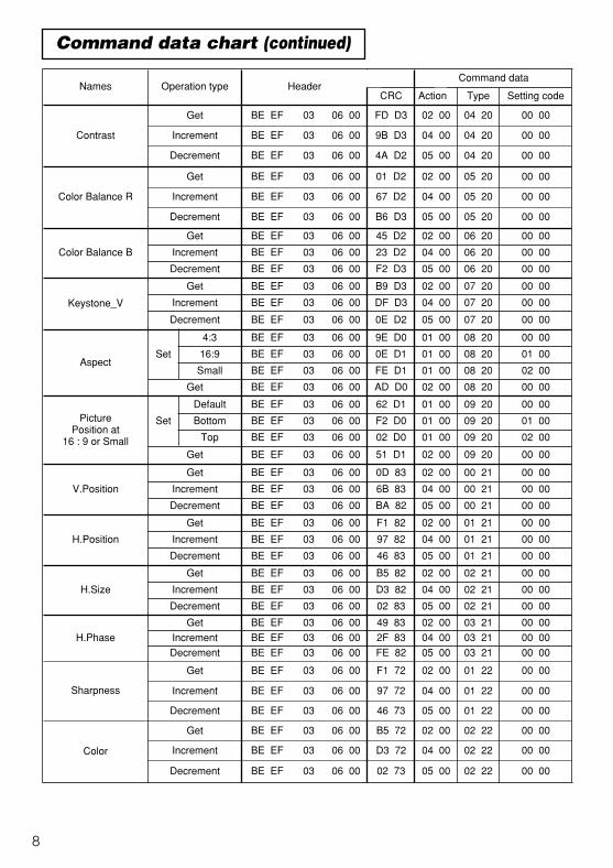
8
Command data chart (continued)
Names Operation type HeaderCommand data
CRC Action Type Setting code
Contrast
Get BE EF 03 06 00 FD D3 02 00 04 20 00 00
Increment BE EF 03 06 00 9B D3 04 00 04 20 00 00
Decrement BE EF 03 06 00 4A D2 05 00 04 20 00 00
Color Balance R
Get BE EF 03 06 00 01 D2 02 00 05 20 00 00
Increment BE EF 03 06 00 67 D2 04 00 05 20 00 00
Decrement BE EF 03 06 00 B6 D3 05 00 05 20 00 00
Color Balance B
Get BE EF 03 06 00 45 D2 02 00 06 20 00 00
Increment BE EF 03 06 00 23 D2 04 00 06 20 00 00
Decrement BE EF 03 06 00 F2 D3 05 00 06 20 00 00
Keystone_V
Get BE EF 03 06 00 B9 D3 02 00 07 20 00 00
Increment BE EF 03 06 00 DF D3 04 00 07 20 00 00
Decrement BE EF 03 06 00 0E D2 05 00 07 20 00 00
AspectSet
4:3 BE EF 03 06 00 9E D0 01 00 08 20 00 00
16:9 BE EF 03 06 00 0E D1 01 00 08 20 01 00
Small BE EF 03 06 00 FE D1 01 00 08 20 02 00
Get BE EF 03 06 00 AD D0 02 00 08 20 00 00
PicturePosition at
16 : 9 or Small
Set
Default BE EF 03 06 00 62 D1 01 00 09 20 00 00
Bottom BE EF 03 06 00 F2 D0 01 00 09 20 01 00
Top BE EF 03 06 00 02 D0 01 00 09 20 02 00
Get BE EF 03 06 00 51 D1 02 00 09 20 00 00
V.Position
Get BE EF 03 06 00 0D 83 02 00 00 21 00 00
Increment BE EF 03 06 00 6B 83 04 00 00 21 00 00
Decrement BE EF 03 06 00 BA 82 05 00 00 21 00 00
H.Position
Get BE EF 03 06 00 F1 82 02 00 01 21 00 00
Increment BE EF 03 06 00 97 82 04 00 01 21 00 00
Decrement BE EF 03 06 00 46 83 05 00 01 21 00 00
H.Size
Get BE EF 03 06 00 B5 82 02 00 02 21 00 00
Increment BE EF 03 06 00 D3 82 04 00 02 21 00 00
Decrement BE EF 03 06 00 02 83 05 00 02 21 00 00
H.Phase
Get BE EF 03 06 00 49 83 02 00 03 21 00 00
Increment BE EF 03 06 00 2F 83 04 00 03 21 00 00
Decrement BE EF 03 06 00 FE 82 05 00 03 21 00 00
Sharpness
Get BE EF 03 06 00 F1 72 02 00 01 22 00 00
Increment BE EF 03 06 00 97 72 04 00 01 22 00 00
Decrement BE EF 03 06 00 46 73 05 00 01 22 00 00
Color
Get BE EF 03 06 00 B5 72 02 00 02 22 00 00
Increment BE EF 03 06 00 D3 72 04 00 02 22 00 00
Decrement BE EF 03 06 00 02 73 05 00 02 22 00 00
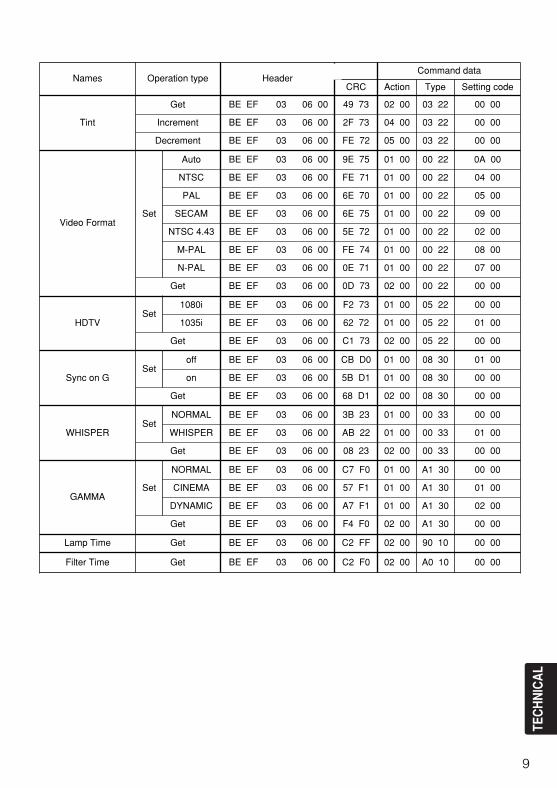
TEC
HN
ICA
L
9
Names Operation type HeaderCommand data
CRC Action Type Setting code
Tint
Get BE EF 03 06 00 49 73 02 00 03 22 00 00
Increment BE EF 03 06 00 2F 73 04 00 03 22 00 00
Decrement BE EF 03 06 00 FE 72 05 00 03 22 00 00
Video FormatSet
Auto BE EF 03 06 00 9E 75 01 00 00 22 0A 00
NTSC BE EF 03 06 00 FE 71 01 00 00 22 04 00
PAL BE EF 03 06 00 6E 70 01 00 00 22 05 00
SECAM BE EF 03 06 00 6E 75 01 00 00 22 09 00
NTSC 4.43 BE EF 03 06 00 5E 72 01 00 00 22 02 00
M-PAL BE EF 03 06 00 FE 74 01 00 00 22 08 00
N-PAL BE EF 03 06 00 0E 71 01 00 00 22 07 00
Get BE EF 03 06 00 0D 73 02 00 00 22 00 00
HDTVSet
1080i BE EF 03 06 00 F2 73 01 00 05 22 00 00
1035i BE EF 03 06 00 62 72 01 00 05 22 01 00
Get BE EF 03 06 00 C1 73 02 00 05 22 00 00
Sync on GSet
off BE EF 03 06 00 CB D0 01 00 08 30 01 00
on BE EF 03 06 00 5B D1 01 00 08 30 00 00
Get BE EF 03 06 00 68 D1 02 00 08 30 00 00
WHISPERSet
NORMAL BE EF 03 06 00 3B 23 01 00 00 33 00 00
WHISPER BE EF 03 06 00 AB 22 01 00 00 33 01 00
Get BE EF 03 06 00 08 23 02 00 00 33 00 00
GAMMASet
NORMAL BE EF 03 06 00 C7 F0 01 00 A1 30 00 00
CINEMA BE EF 03 06 00 57 F1 01 00 A1 30 01 00
DYNAMIC BE EF 03 06 00 A7 F1 01 00 A1 30 02 00
Get BE EF 03 06 00 F4 F0 02 00 A1 30 00 00
Lamp Time Get BE EF 03 06 00 C2 FF 02 00 90 10 00 00
Filter Time Get BE EF 03 06 00 C2 F0 02 00 A0 10 00 00

Printed in Japan*QR55481*
Hitachi America, Ltd.Computer Division 2000 Sierra Point Parkway,MS760 Brisbane, CA 94005-1835Tel: +1-800-225-1741 Fax: +1-650-244-7776www.hitachi.com/lcd.
Hitachi Canada, Ltd.6740 Campobello Road, Mississauga, OntarioL5N2L8, CanadaTel: +1-905-821-4545 Fax: +1-905-821-1101
Hitachi Home Electronics (Europe), Ltd.Dukes Meadow, Millboard Road, Bourne End ,Buckinghamshire SL8 5XF UKTel: +44-162-864-3000 Fax: +44-162-864-3400
Hitachi Home Electronics Europe Ltd426 Bergensesteenweg, 1500 Halle, BelgiumTel: +32-2-363-9901 Fax: +34-2-363-9900
Hitachi Home Electronics Europe LtdGewerbepark, Hintermattlistr, Postfach, 5506Magenwil, SwitzerlandTel: +41-62-889-8011 Fax: +41-62-896-4771
Hitachi Europe GmbHBusiness Systems DivisionVia T. Gulli. 39, 20147 Milano, ItalyTel: +39-2-487861 Fax: +39-2-48786322
Hitachi Sales Europe GmbHBusiness Systems DivisionAm Seestern 18, 40547 Dusseldorf, GermanyTel: +49-211-529-1551 Fax: +49-211-529-1594
Hitachi Business Systems (Nordic)Brugata 14, N-0184 Oslo, NorwayTel: +47-2205-9060 Fax: +47-2205-9061
Hitachi Business Systems (Nordic)Domnarvsgatan 29, Lunda, Box 62, S-163 91Spanga, SwedenTel: +46-8-621-8260 Fax: +46-8-761-6250
Hitachi Business Systems (Nordic)Kuldyssen 13, DK-2630 Tåstrup, DenmarkTel: +45-43-99-9200 Fax: +45-43-99-9392
Hitachi Business Systems (Nordic)Tapiolan Keskustorni 11 Krs. Fin-02100 Espoo,FinlandTel: +358-9-3487-1188 Fax: +358-9-455-2152
Hitachi FranceImmeuble, 'Ariane', 18 Rue Grange Dame Rose,B.P. 134, 78148 Velizy, Cedex, FranceTel: +33-1-34630542 Fax: +33-1-34650761
Hitachi Sales Iberica S AGran Via Carlos 111, 101, 1-1, 08028 Barcelona,SpainTel: +34-3-330-8652 Fax: +34-3-339-7839
Hitachi Home Electronics Asia, (S) Pte Ltd.16 Collyer Quay #20-00 Hitachi Tower Singapore049318, SingaporeTel: +65-536-2520 Fax: +65-536-2521
Hitachi Sales (Malaysia) Sdn. Bhd.Wisma Hitachi, No.2, Lorong 13/6A, 46200PetalingJaya, Selangor Darul Ehsan, MalaysiaTel: +60-3-7573455 Fax: +60-3-7556090
Hitachi Sales (Thailand), Ltd.994,996 Soi Thonglor, Sukhumvit 55 Road,Klongton,Klongtoey, Bangkok 10110, ThailandTel: +66-2-381-8381 Fax: +66-2-381-9520
Hitachi (Hong Kong), Ltd.8th Floor Park-in Commercial Centre, No.56,DundasStreet, Kowloon Bay, Kowloon, Hong KongTel: +852-2-7804351 Fax: +852-2-7804915
Hitachi Sales Corp. of Taiwan.2nd Floor, No.65, Nanking East Road, Section 3,Taipei, TaiwanTel: +886-2-516-0500 Fax: +886-2-516-1501
Hitachi Australia Ltd.13-15 Lyonpark Road, North Ryde NSW 2113,AustraliaTel: +61-2-9888-4100 Fax: +61-2-9888-4144
Hitachi, Ltd.15-12, Nishi Simbashi 2-chome, Minato-ku, Tokyo,105 JapanTel: +81-3-3502-2111 Fax: +81-3-3506-1440
00CP-S225/X75/Extended/再 02.10.16 5:17 PM ページ1


![*X275/12/02* - prestwick.sayr.sch.uk · [X275/12/02] Page two Read carefully 1 Check that the answer sheet provided is for Human Biology Higher (Revised) (Section A). 2 For this section](https://img.dokumen.tips/doc/110x75/5f0df2077e708231d43cdb8b/x2751202-x2751202-page-two-read-carefully-1-check-that-the-answer-sheet.jpg)