Embed Size (px)
Citation preview
R01AN2600EJ0140 Rev.1.40 Page 1 of 57Jun. 07, 2018
RZ/T1 GroupCMTW & ELC Sample Program
APPLICATION NOTE
IntroductionThis application note explains a sample program that performs A/D conversion based on the linkage between the timer and the ADC function by using the 32-bit timer (CMTW) and the event link controller (ELC) of RZ/T1.
The major features of the CMTW & ELC sample 2014.11.04 program are listed below. • Compare matches of the timer occur at intervals of 3 seconds.• When a compare match of the timer occurs, the input voltage to the potentiometer is A/D converted. • Conversion results are classified into four scales, which are displayed to LED0, LED1, LED2, and LED3
respectively.
Target DevicesRZ/T1
When applying the sample program covered in this application note to another microcomputer, modify the program according to the specifications for the target microcomputer and conduct an extensive evaluation of the modified program.
R01AN2600EJ0140Rev.1.40
Jun. 07, 2018
Introduction
1. Specifications.................................................................................................................................... 4
2. Operating Environment ..................................................................................................................... 5
3. Related Application Note .................................................................................................................. 6
4. Peripheral Functions ......................................................................................................................... 7
5. Hardware .......................................................................................................................................... 85.1 Hardware Configuration Example........................................................................................... 85.2 Pins......................................................................................................................................... 8
6. Software............................................................................................................................................ 96.1 Operation Outline.................................................................................................................... 9
6.1.1 Project Settings ............................................................................................................ 10
6.1.2 Preparation for Use ...................................................................................................... 106.2 Memory Map......................................................................................................................... 11
6.2.1 Section Arrangement of the Sample Program.............................................................. 116.2.2 MPU Settings................................................................................................................ 116.2.3 Exception Handling Vector Table ................................................................................. 11
6.3 Interrupts............................................................................................................................... 116.4 Fixed-Width Integer Types.................................................................................................... 116.5 Constants/Error Codes ......................................................................................................... 12
6.5.1 Constants for the Sample Code ................................................................................... 126.5.2 Constants for the CMTW Driver ................................................................................... 136.5.3 Constants for the ELC Driver........................................................................................ 16
6.6 Structures/Unions/Enumerated Types.................................................................................. 236.7 Global Variables ................................................................................................................... 286.8 Functions .............................................................................................................................. 296.9 Specification of Functions..................................................................................................... 30
6.9.1 R_CMTW_Open........................................................................................................... 30
6.9.2 R_CMTW_Close........................................................................................................... 316.9.3 R_CMTW_StartPeriodic ............................................................................................... 316.9.4 R_CMTW_StartOneShot .............................................................................................. 32
6.9.5 R_CMTW_Control ........................................................................................................ 326.9.6 R_CMTW_GetVersion.................................................................................................. 33
6.9.7 cmtw<n>_cmwi_isr ....................................................................................................... 336.9.8 cmtw<n>_ic<m>i_isr..................................................................................................... 336.9.9 cmtw<n>_oc<m>i_isr ................................................................................................... 34
6.9.10 R_ELC_Open ............................................................................................................... 346.9.11 R_ELC_Close............................................................................................................... 346.9.12 R_ELC_LinkStart.......................................................................................................... 35
6.9.13 R_ELC_LinkStop .......................................................................................................... 356.9.14 R_ELC_Control ............................................................................................................ 356.9.15 R_ELC_GetVersion ...................................................................................................... 36
Table of Contents
6.9.16 elc_elci<n>_isr.............................................................................................................. 36
6.9.17 main.............................................................................................................................. 366.9.18 CMTW_Cmwi_Callback................................................................................................ 37
6.9.19 CMTW_Ic0i_Callback ................................................................................................... 376.9.20 CMTW_Oc0i_Callback ................................................................................................. 376.9.21 ELC_Elci_Callback ....................................................................................................... 38
6.10 Flowchart .............................................................................................................................. 396.10.1 Main Processing of the Sample Program..................................................................... 39
6.10.2 CMTW_Sample_Callback ............................................................................................ 416.10.3 cmtw0_cmwi_isr ........................................................................................................... 41
6.11 R_CMTW_Control Commands ............................................................................................. 426.11.1 CMTW_CMD_SET_TIME_CNT ................................................................................... 426.11.2 CMTW_CMD_SET_MODE .......................................................................................... 43
6.11.3 CMTW_CMD_SET_PAUSE......................................................................................... 446.11.4 CMTW_CMD_SET_RESUME...................................................................................... 446.11.5 CMTW_CMD_SET_RESTART .................................................................................... 45
6.11.6 CMTW_CMD_SET_ECM ............................................................................................. 456.11.7 CMTW_CMD_GET_STATUS....................................................................................... 46
6.12 R_ELC_Control Commands ................................................................................................. 476.12.1 ELC_CMD_SET_EVENT_MTU.................................................................................... 476.12.2 ELC_CMD_SET_EVENT_CMT.................................................................................... 48
6.12.3 ELC_CMD_SET_EVENT_DSMIF ................................................................................ 486.12.4 ELC_CMD_SET_EVENT_S12AD................................................................................ 496.12.5 ELC_CMD_SET_EVENT_INTR................................................................................... 49
6.12.6 ELC_CMD_SET_EVENT_OUT_PORT_GROUP......................................................... 506.12.7 ELC_CMD_SET_EVENT_IN_PORT_GROUP............................................................. 506.12.8 ELC_CMD_SET_EVENT_SINGLE_PORT .................................................................. 51
6.12.9 ELC_CMD_SET_EVENT_CMTW ................................................................................ 526.12.10 ELC_CMD_SET_EVENT_TPU .................................................................................... 526.12.11 ELC_CMD_SET_EVENT_GPT.................................................................................... 53
6.12.12 ELC_CMD_SET_PORT_GROUP ................................................................................ 536.12.13 ELC_CMD_SET_SOFTWARE_EVENT....................................................................... 54
6.12.14 ELC_CMD_GET_PORT_GROUP_VALUE.................................................................. 54
7. Sample Code .................................................................................................................................. 55
8. Related Documents ........................................................................................................................ 56
R01AN2600EJ0140 Rev.1.40 Page 4 of 57Jun. 07, 2018
RZ/T1 Group CMTW & ELC Sample Program
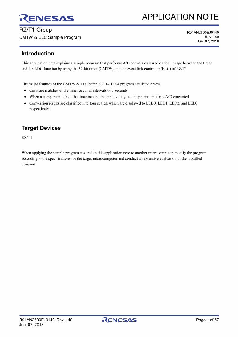
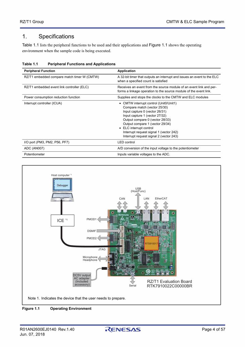
1. SpecificationsTable 1.1 lists the peripheral functions to be used and their applications and Figure 1.1 shows the operating environment when the sample code is being executed.
Table 1.1 Peripheral Functions and Applications
Peripheral Function Application
RZ/T1 embedded compare match timer W (CMTW) A 32-bit timer that outputs an interrupt and issues an event to the ELC when a specified count is satisfied
RZ/T1 embedded event link controller (ELC) Receives an event from the source module of an event link and per-forms a linkage operation to the source module of the event link.
Power consumption reduction function Supplies and stops the clocks to the CMTW and ELC modules
Interrupt controller (ICUA) • CMTW interrupt control (Unit0/Unit1)Compare match (vector 25/30)Input capture 0 (vector 26/31)Input capture 1 (vector 27/32)Output compare 0 (vector 28/33)Output compare 1 (vector 29/34)
• ELC interrupt controlInterrupt request signal 1 (vector 242) Interrupt request signal 2 (vector 243)
I/O port (PM3, PM2, P56, PF7) LED control
ADC (AN007) A/D conversion of the input voltage to the potentiometer
Potentiometer Inputs variable voltages to the ADC.
Note 1. Indicates the device that the user needs to prepare.
Figure 1.1 Operating Environment
CAN
USB(Host/Func)
LAN EtherCAT
R7S910017
PMOD1
DSMIF
PMOD2
JTAG
RZ/T1 Evaluation BoardRTK7910022C00000BR
Host computer *1
MicrophoneHeadphone
Serial
ICE *1
DC5V output AC adapter (Included accessory)
R01AN2600EJ0140 Rev.1.40 Page 5 of 57Jun. 07, 2018
RZ/T1 Group CMTW & ELC Sample Program
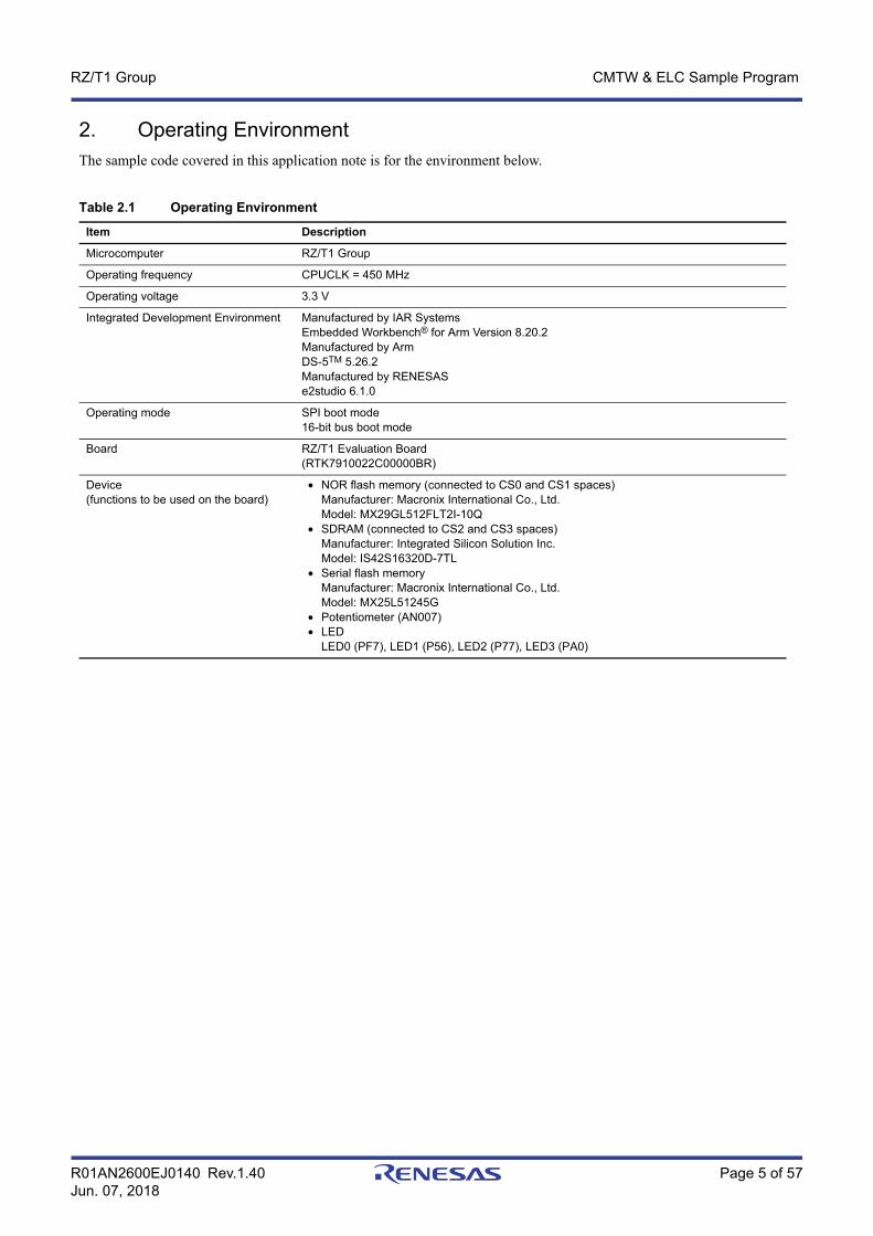
2. Operating EnvironmentThe sample code covered in this application note is for the environment below.
Table 2.1 Operating Environment
Item Description
Microcomputer RZ/T1 Group
Operating frequency CPUCLK = 450 MHz
Operating voltage 3.3 V
Integrated Development Environment Manufactured by IAR SystemsEmbedded Workbench® for Arm Version 8.20.2Manufactured by ArmDS-5TM 5.26.2Manufactured by RENESASe2studio 6.1.0
Operating mode SPI boot mode16-bit bus boot mode
Board RZ/T1 Evaluation Board(RTK7910022C00000BR)
Device (functions to be used on the board)
• NOR flash memory (connected to CS0 and CS1 spaces)Manufacturer: Macronix International Co., Ltd.Model: MX29GL512FLT2I-10Q
• SDRAM (connected to CS2 and CS3 spaces)Manufacturer: Integrated Silicon Solution Inc.Model: IS42S16320D-7TL
• Serial flash memoryManufacturer: Macronix International Co., Ltd.Model: MX25L51245G
• Potentiometer (AN007)• LED
LED0 (PF7), LED1 (P56), LED2 (P77), LED3 (PA0)
R01AN2600EJ0140 Rev.1.40 Page 6 of 57Jun. 07, 2018
RZ/T1 Group CMTW & ELC Sample Program
3. Related Application NoteThe application notes related to this application note are listed below for reference.
• Application Note: RZ/T1 Group Initial Settings (R01AN2554EJ) • Application Note: RZ/T1 Group ADC Sample Program (R01AN2599EJ)
Note: Registers not mentioned in this application note should be used at a value set in the Application Note: RZ/T1 Group Initial Settings.
R01AN2600EJ0140 Rev.1.40 Page 7 of 57Jun. 07, 2018
RZ/T1 Group CMTW & ELC Sample Program
4. Peripheral FunctionsThe basics of the operating mode used in event links, compare match timer W (CMTW), event link controller (ELC), power consumption reduction function, interrupt controller (ICUA), I/O ports, multi-function pin controller (MPC), and 12-bit A/D converter (S12ADCa) are described in the RZ/T1 Group User’s Manual: Hardware.
R01AN2600EJ0140 Rev.1.40 Page 8 of 57Jun. 07, 2018
RZ/T1 Group CMTW & ELC Sample Program
5. Hardware
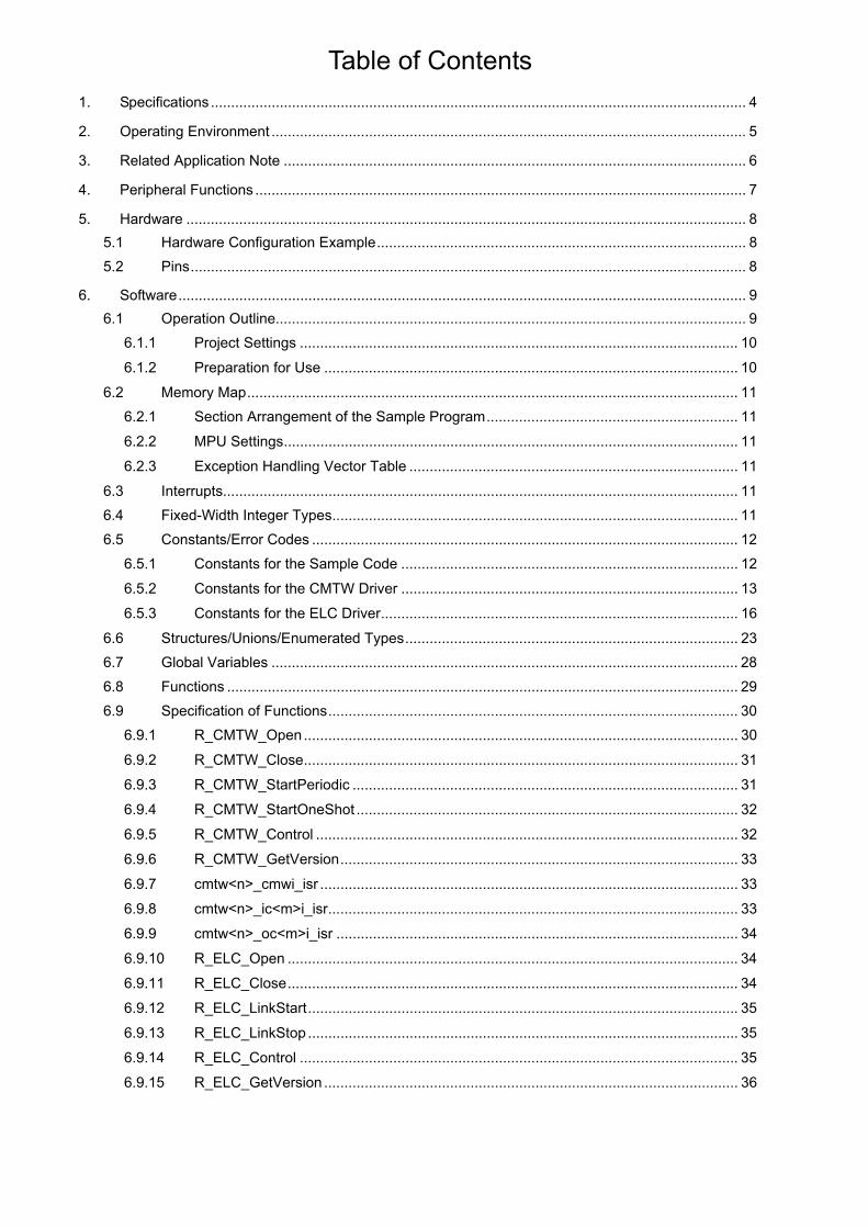
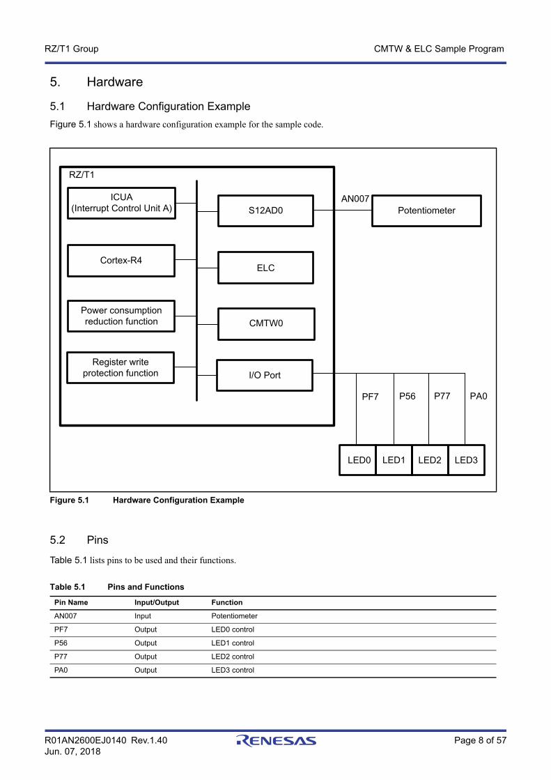
5.1 Hardware Configuration ExampleFigure 5.1 shows a hardware configuration example for the sample code.
5.2 Pins
Table 5.1 lists pins to be used and their functions.
Figure 5.1 Hardware Configuration Example
Table 5.1 Pins and Functions
Pin Name Input/Output Function
AN007 Input Potentiometer
PF7 Output LED0 control
P56 Output LED1 control
P77 Output LED2 control
PA0 Output LED3 control
PF7 P56 P77 PA0
ELC
ICUA(Interrupt Control Unit A)
Cortex-R4
RZ/T1
Register write protection function
Power consumption reduction function
S12AD0 Potentiometer
CMTW0
I/O Port
AN007
LED3LED0 LED1 LED2

R01AN2600EJ0140 Rev.1.40 Page 9 of 57Jun. 07, 2018
RZ/T1 Group CMTW & ELC Sample Program
6. Software
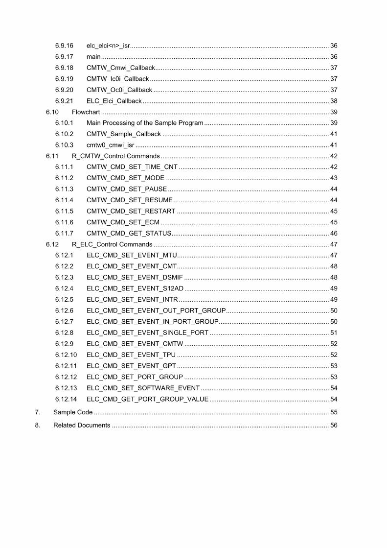
6.1 Operation OutlineTable 6.1 Operation Outline lists the functional outlines of the CMTW & ELC sample program. Figure 6.1 shows the system block diagram.
Table 6.1 Operation Outline
Function Outline
Operation outline • The following items 1 to 4 are executed repeatedly. 1. An event occurs due to a CMTW compare match.2. The ELC distributes the event to the ADC.3. A/D conversion in the ADC4. A/D conversion results are classified into four scales, and the LED assigned to the relevant scale is turned on. 5. When an A/D conversion result exceeds the maximum value (fourth scale), the processing of the sample program is terminated.
Channel number (CMTW) • ch0 is selected
Operation mode (CMTW) • Only compare match is set.
Compare match period (CMTW)
• Approximately 3 seconds(Input clock to the timer counter: PCLKD/8, compare match count setting: 28125000)
Timer counter clear source (CMTW)
• Compare matchOperates in the timer counter periodic operation.
Link source event (ELC) • CMTW/Channel 0/Compare match
Link destination event (ELC) • S12AD0
A/D conversion start condition • Synchronous trigger startup
ADC driver setting • The following are set.Input channel: AN007Operation mode: Single scan modeConversion start trigger: Synchronous trigger startup (ELC)

R01AN2600EJ0140 Rev.1.40 Page 10 of 57Jun. 07, 2018
RZ/T1 Group CMTW & ELC Sample Program
6.1.1 Project SettingsThe project settings used on the development environment EWARM are described in the Application Note: RZ/T1 Group Initial Settings.
6.1.2 Preparation for UseNo preparation is required for executing this sample program.
Figure 6.1 System Block Diagram
RZ/T1 hardware
ADC sample driver
Sample program
Function call Register access
CMTW sample driver ELC sample driver
CMTW ELC ADC
Event notification

R01AN2600EJ0140 Rev.1.40 Page 11 of 57Jun. 07, 2018
RZ/T1 Group CMTW & ELC Sample Program
6.2 Memory MapThe address space of the RZ/T1 group and the memory mapping of the RZ/T1 evaluation board are described in the Application Note: RZ/T1 Group Initial Settings.
6.2.1 Section Arrangement of the Sample ProgramSections used in the sample program, the section arrangement in the initial state of the sample program (load view), and the section arrangement after the scatter loading function is used (execution view) are described in the Application Note: RZ/T1 Group Initial Settings.
6.2.2 MPU SettingsThe settings of the MPU are described in the Application Note: RZ/T1 Group Initial Settings.
6.2.3 Exception Handling Vector TableThe exception handling vector table is described in the Application Note: RZ/T1 Group Initial Settings.
6.3 InterruptsTable 6.2 lists interrupts for the sample code.
6.4 Fixed-Width Integer TypesTable 6.3 lists fixed-width integers for the sample code.
Table 6.2 Interrupts for the Sample Code
Interrupt (Source ID) Priority Process Outline
Compare match interrupt (25) 7 The callback function is called.
A/D conversion complete interrupt (35) 7 The callback function is called.
Table 6.3 Fixed-width Integers for the Sample Code
Symbol Description
int8_t 8-bit signed integer (defined in the standard library)
int16_t 16-bit signed integer (defined in the standard library)
int32_t 32-bit signed integer (defined in the standard library)
int64_t 64-bit signed integer (defined in the standard library)
uint8_t 8-bit unsigned integer (defined in the standard library)
uint16_t 16-bit unsigned integer (defined in the standard library)
uint32_t 32-bit unsigned integer (defined in the standard library)
uint64_t 64-bit unsigned integer (defined in the standard library)
R01AN2600EJ0140 Rev.1.40 Page 12 of 57Jun. 07, 2018
RZ/T1 Group CMTW & ELC Sample Program
6.5 Constants/Error CodesTable 6.4 lists the constants to be used in relevant drivers in the sample code, Table 6.5 to Table 6.17 list the constants to be used in the CMTW driver, and Table 6.18 to Table 6.40 list the constants to be used in the ELC driver.
Note that this sample code does not use constants to the ELC.
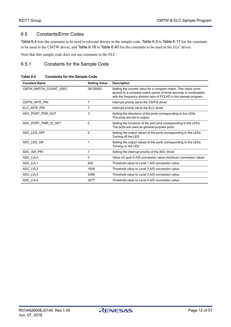
6.5.1 Constants for the Sample Code
Table 6.4 Constants for the Sample Code
Constant Name Setting Value Description
CMTW_MATCH_COUNT_3SEC 28125000 Setting the counter value for a compare match. This value corre-sponds to a compare match period of three seconds in combination with the frequency division ratio of PCLKD in the sample program.
CMTW_INTR_PRI 7 Interrupt priority set to the CMTW driver
ELC_INTR_PRI 7 Interrupt priority set to the ELC driver
ADC_PORT_PDR_OUT 3 Setting the directions of the ports corresponding to the LEDs The ports are set to output.
ADC_PORT_PMR_IO_SET 0 Setting the functions of the port pins corresponding to the LEDs The ports are used as general-purpose ports.
ADC_LED_OFF 0 Setting the output values of the ports corresponding to the LEDsTurning off the LED
ADC_LED_ON 1 Setting the output values of the ports corresponding to the LEDsTurning on the LED
ADC_ADI_PRI 7 Setting the interrupt priority of the ADC driver
ADC_LVL0 0 Value of Level 0 A/D conversion value (minimum conversion value)
ADC_LVL1 820 Threshold value to Level 1 A/D conversion value
ADC_LVL2 1639 Threshold value to Level 2 A/D conversion value
ADC_LVL3 2458 Threshold value to Level 3 A/D conversion value
ADC_LVL4 3277 Threshold value to Level 4 A/D conversion value

R01AN2600EJ0140 Rev.1.40 Page 13 of 57Jun. 07, 2018
RZ/T1 Group CMTW & ELC Sample Program
6.5.2 Constants for the CMTW Driver
Table 6.5 Error Codes for the Sample Code (CMTW)
Constant Name Setting Value Description
CMTW_SUCCESS 0 The function terminates normally.
CMTW_ERR_INVALID_CH 1 A nonexistent channel is specified.
CMTW_ERR_INVALID_ARG 2 The setting parameter has an abnormal value.
CMTW_ERR_NOT_OPENED 3 The function is executed in an uninitialized state.
CMTW_ERR_NOT_CLOSED 4 Initialization of the API is duplicated.
CMTW_ERR_TIMER_RUNNING 5 The function is executed while the timer is running.
CMTW_ERR_TIMER_STOP 6 The timer is executed while the timer count has been stopped.
CMTW_ERR_MISSING_PTR 7 Incorrect pointer argument
Table 6.6 Definitions for CMTW Version
Constant Name Value Description
CMTW_VERSION_MAJOR 1 Major version of the CMTW sample driver
CMTW_VERSION_MINOR 0 Minor version of the CMTW sample driver
Table 6.7 Definitions for CMTW Driver Channel Number
Constant Name Value Description
CMTW_CH_0 0 Specifying the Channel 0
CMTW_CH_1 1 Specifying the Channel 1
CMTW_CH_NUM 2 Used for checking the range of normal setting values. Indicating the number of CMTW channels.
Table 6.8 CMTW Command Definitions
Constant Name Value Description
CMTW_CMD_SET_TIME_CNT 0 Timer count setting command
CMTW_CMD_SET_MODE 1 Timer mode setting command
CMTW_CMD_SET_PAUSE 2 Pause command
CMTW_CMD_SET_RESUME 3 Resume command
CMTW_CMD_SET_RESTART 4 Restart command
CMTW_CMD_SET_ECM 5 ECM dynamic mode error setting
CMTW_CMD_GET_STATUS 6 Status acquisition command

R01AN2600EJ0140 Rev.1.40 Page 14 of 57Jun. 07, 2018
RZ/T1 Group CMTW & ELC Sample Program
Table 6.9 Definitions for Setting Timer Clock Frequency Division Ratio
Constant Name Value Description
CMTW_PCLK_DIV_8 0 Selecting PCLKD/8 as the timer frequency division ratio
CMTW_PCLK_DIV_32 1 Selecting PCLKD/32 as the timer frequency division ratio
CMTW_PCLK_DIV_128 2 Selecting PCLKD/128 as the timer frequency division ratio
CMTW_PCLK_DIV_512 3 Selecting PCLKD/512 as the timer frequency division ratio
CMTW_PCLK_DIV_MAX_OVER 4 For checking the range of normal setting values
Table 6.10 Definitions for Setting Timer Counter Length
Constant Name Value Description
CMTW_CNT_SIZE_32BIT 0 Selecting 32 bits as the counter size
CMTW_CNT_SIZE_16BIT 1 Selecting 16 bits as the counter size
CMTW_CNT_SIZE_MAX_OVER 2 For checking the range of normal setting values
Table 6.11 Definitions for Setting Timer Counter Clear Source
Constant Name Value Description
CMTW_CNT_CLEAR_COMPARE_MATCH 0 Selecting compare match as the counter clear source
CMTW_CNT_CLEAR_INPUT_CAPTURE0 1 Selecting input capture 0 as the counter clear source
CMTW_CNT_CLEAR_INPUT_CAPTURE1 2 Selecting input capture 1 as the counter clear source
CMTW_CNT_CLEAR_OUTPUT_COMPARE0 3 Selecting output compare 0 as the counter clear source
CMTW_CNT_CLEAR_OUTPUT_COMPARE1 4 Selecting output compare 1 as the counter clear source
CMTW_CNT_CLEAR_NONE 5 Selecting counter clear source none
CMTW_CNT_CLEAR_MAX_OVER 6 For checking the range of normal setting values
Table 6.12 Definitions for Output Compare Output Setting
Constant Name Value Description
CMTW_OUT_COMPARE_VALUE_HOLD 0 The output value does not change during output compare.
CMTW_OUT_COMPARE_VALUE_0_TO_TOGGLE 1 The output value start at an initial value of 0 and toggles during output compare.
CMTW_OUT_COMPARE_VALUE_1_TO_TOGGLE 2 The output value start at an initial value of 1 and toggles during output compare.
CMTW_OUT_COMPARE_VALUE_MAX_OVER 3 For checking the range of normal setting values
Table 6.13 Definitions for Setting Input Capture Detection Trigger
Constant Name Value Description
CMTW_IN_CAPTURE_TRIGGER_UP 0 Setting the input capture trigger to rising edge
CMTW_IN_CAPTURE_TRIGGER_DOWN 1 Setting the input capture trigger to falling edge
CMTW_IN_CAPTURE_TRIGGER_UP_DOWN 2 Setting the input capture trigger to both rising and falling edges
CMTW_IN_CAPTURE_TRIGGER_MAX_OVER 3 For checking the range of normal setting values
R01AN2600EJ0140 Rev.1.40 Page 15 of 57Jun. 07, 2018
RZ/T1 Group CMTW & ELC Sample Program
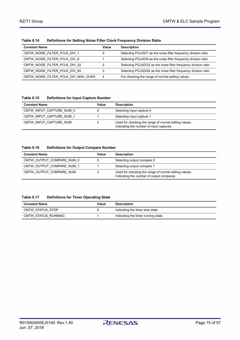
Table 6.14 Definitions for Setting Noise Filter Clock Frequency Division Ratio
Constant Name Value Description
CMTW_NOISE_FILTER_PCLK_DIV_1 0 Selecting PCLKD/1 as the noise filter frequency division ratio
CMTW_NOISE_FILTER_PCLK_DIV_8 1 Selecting PCLKD/8 as the noise filter frequency division ratio
CMTW_NOISE_FILTER_PCLK_DIV_32 2 Selecting PCLKD/32 as the noise filter frequency division ratio
CMTW_NOISE_FILTER_PCLK_DIV_64 3 Selecting PCLKD/64 as the noise filter frequency division ratio
CMTW_NOISE_FILTER_PCLK_DIV_MAX_OVER 4 For checking the range of normal setting values
Table 6.15 Definitions for Input Capture Number
Constant Name Value Description
CMTW_INPUT_CAPTURE_NUM_0 0 Selecting input capture 0
CMTW_INPUT_CAPTURE_NUM_1 1 Selecting input capture 1
CMTW_INPUT_CAPTURE_NUM 2 Used for checking the range of normal setting values. Indicating the number of input captures.
Table 6.16 Definitions for Output Compare Number
Constant Name Value Description
CMTW_OUTPUT_COMPARE_NUM_0 0 Selecting output compare 0
CMTW_OUTPUT_COMPARE_NUM_1 1 Selecting output compare 1
CMTW_OUTPUT_COMPARE_NUM 2 Used for checking the range of normal setting values. Indicating the number of output compares.
Table 6.17 Definitions for Timer Operating State
Constant Name Value Description
CMTW_STATUS_STOP 0 Indicating the timer stop state
CMTW_STATUS_RUNNING 1 Indicating the timer running state

R01AN2600EJ0140 Rev.1.40 Page 16 of 57Jun. 07, 2018
RZ/T1 Group CMTW & ELC Sample Program
6.5.3 Constants for the ELC Driver
Table 6.18 Error Codes for the Sample Code (ELC)
Constant Name Setting Value Description
ELC_SUCCESS_OK 0 The function terminates normally.
ELC_ERR_INVALID_ARG 1 The setting parameter has an abnormal value.
ELC_ERR_NOT_OPENED 2 The function is executed in an uninitialized state.
ELC_ERR_NOT_CLOSED 3 The API is initialized twice.
ELC_ERR_MISSING_PTR 4 Incorrect pointer argument
Table 6.19 Definitions for ELC Driver Version
Constant Name Value Description
ELC_VERSION_MAJOR 1 Major version of the ELC sample driver
ELC_VERSION_MINOR 0 Minor version of the ELC sample driver
Table 6.20 ELC Command Definitions
Constant Name Value Description
ELC_CMD_SET_EVENT_MTU 0 MTU event link setting command
ELC_CMD_SET_EVENT_CMT 1 CMT event link setting command
ELC_CMD_SET_EVENT_DSMIF 2 ΔΣ unit event link setting command
ELC_CMD_SET_EVENT_S12AD 3 12-bit A/D converter event link setting command
ELC_CMD_SET_EVENT_INTR 4 ELC interrupt request signal event link setting command
ELC_CMD_SET_EVENT_OUT_PORT_GROUP 5 Output port group event link setting command
ELC_CMD_SET_EVENT_IN_PORT_GROUP 6 Input port group event link setting command
ELC_CMD_SET_EVENT_SINGLE_PORT 7 Single port registration event link setting command
ELC_CMD_SET_EVENT_CMTW 8 CMTW event link setting command
ELC_CMD_SET_EVENT_TPU 9 TPU event link setting command
ELC_CMD_SET_EVENT_GPT 10 GPT event link setting command
ELC_CMD_SET_PORT_GROUP 11 Port group setting command
ELC_CMD_SET_SOFTWARE_EVENT 12 Software event issuance command
ELC_CMD_GET_PORT_GROUP_VALUE 13 Input port group value acquisition command
R01AN2600EJ0140 Rev.1.40 Page 17 of 57Jun. 07, 2018
RZ/T1 Group CMTW & ELC Sample Program
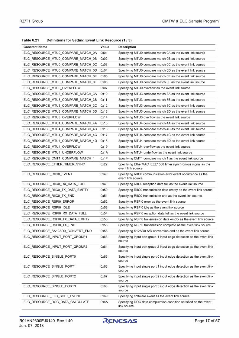
Table 6.21 Definitions for Setting Event Link Resource (1 / 3)
Constant Name Value Description
ELC_RESOURCE_MTU0_COMPARE_MATCH_0A 0x01 Specifying MTU0 compare match 0A as the event link source
ELC_RESOURCE_MTU0_COMPARE_MATCH_0B 0x02 Specifying MTU0 compare match 0B as the event link source
ELC_RESOURCE_MTU0_COMPARE_MATCH_0C 0x03 Specifying MTU0 compare match 0C as the event link source
ELC_RESOURCE_MTU0_COMPARE_MATCH_0D 0x04 Specifying MTU0 compare match 0D as the event link source
ELC_RESOURCE_MTU0_COMPARE_MATCH_0E 0x05 Specifying MTU0 compare match 0E as the event link source
ELC_RESOURCE_MTU0_COMPARE_MATCH_0F 0x06 Specifying MTU0 compare match 0F as the event link source
ELC_RESOURCE_MTU0_OVERFLOW 0x07 Specifying MTU0 overflow as the event link source
ELC_RESOURCE_MTU3_COMPARE_MATCH_3A 0x10 Specifying MTU3 compare match 3A as the event link source
ELC_RESOURCE_MTU3_COMPARE_MATCH_3B 0x11 Specifying MTU3 compare match 3B as the event link source
ELC_RESOURCE_MTU3_COMPARE_MATCH_3C 0x12 Specifying MTU3 compare match 3C as the event link source
ELC_RESOURCE_MTU3_COMPARE_MATCH_3D 0x13 Specifying MTU3 compare match 3D as the event link source
ELC_RESOURCE_MTU3_OVERFLOW 0x14 Specifying MTU3 overflow as the event link source
ELC_RESOURCE_MTU4_COMPARE_MATCH_4A 0x15 Specifying MTU4 compare match 4A as the event link source
ELC_RESOURCE_MTU4_COMPARE_MATCH_4B 0x16 Specifying MTU4 compare match 4B as the event link source
ELC_RESOURCE_MTU4_COMPARE_MATCH_4C 0x17 Specifying MTU4 compare match 4C as the event link source
ELC_RESOURCE_MTU4_COMPARE_MATCH_4D 0x18 Specifying MTU4 compare match 4D as the event link source
ELC_RESOURCE_MTU4_OVERFLOW 0x19 Specifying MTU4 overflow as the event link source
ELC_RESOURCE_MTU4_UNDERFLOW 0x1A Specifying MTU4 underflow as the event link source
ELC_RESOURCE_CMT1_COMPARE_MATCH_1 0x1F Specifying CMT1 compare match 1 as the event link source
ELC_RESOURCE_ETHER_TIMER_SYNC 0x22 Specifying EtherMAC IEEE1588 timer synchronous signal as the event link source
ELC_RESOURCE_RIIC0_EVENT 0x4E Specifying RIIC0 communication error event occurrence as the event link source
ELC_RESOURCE_RIIC0_RX_DATA_FULL 0x4F Specifying RIIC0 reception data full as the event link source
ELC_RESOURCE_RIIC0_TX_DATA_EMPTY 0x50 Specifying RIIC0 transmission data empty as the event link source
ELC_RESOURCE_RIIC0_TX_END 0x51 Specifying RIIC0 transmission end as the event link source
ELC_RESOURCE_RSPI0_ERROR 0x52 Specifying RSPI0 error as the event link source
ELC_RESOURCE_RSPI0_IDLE 0x53 Specifying RSPI0 idle as the event link source
ELC_RESOURCE_RSPI0_RX_DATA_FULL 0x54 Specifying RSPI0 reception data full as the event link source
ELC_RESOURCE_RSPI0_TX_DATA_EMPTY 0x55 Specifying RSPI0 transmission data empty as the event link source
ELC_RESOURCE_RSPI0_TX_END 0x56 Specifying RSPI0 transmission complete as the event link source
ELC_RESOURCE_SA12AD0_CONVERT_END 0x58 Specifying S12AD0 A/D conversion end as the event link source
ELC_RESOURCE_INPUT_PORT_GROUP1 0x63 Specifying input port group 1 input edge detection as the event link source
ELC_RESOURCE_INPUT_PORT_GROUP2 0x64 Specifying input port group 2 input edge detection as the event link source
ELC_RESOURCE_SINGLE_PORT0 0x65 Specifying input single port 0 input edge detection as the event link source
ELC_RESOURCE_SINGLE_PORT1 0x66 Specifying input single port 1 input edge detection as the event link source
ELC_RESOURCE_SINGLE_PORT2 0x67 Specifying input single port 2 input edge detection as the event link source
ELC_RESOURCE_SINGLE_PORT3 0x68 Specifying input single port 3 input edge detection as the event link source
ELC_RESOURCE_ELC_SOFT_EVENT 0x69 Specifying software event as the event link source
ELC_RESOURCE_DOC_DATA_CALCULATE 0x6A Specifying DOC data computation condition satisfied as the event link source

R01AN2600EJ0140 Rev.1.40 Page 18 of 57Jun. 07, 2018
RZ/T1 Group CMTW & ELC Sample Program
ELC_RESOURCE_SA12AD1_CONVERT_END 0x6C Specifying S12AD1 A/D conversion end as the event link source
ELC_RESOURCE_CMTW0_COMPARE_MATCH 0x7E Specifying CMTW0 compare match as the event link source
ELC_RESOURCE_GPT0_COMPARE_MATCH_A 0x80 Specifying GPT0 compare match A as the event link source
ELC_RESOURCE_GPT0_COMPARE_MATCH_B 0x81 Specifying GPT0 compare match B as the event link source
ELC_RESOURCE_GPT0_COMPARE_MATCH_C 0x82 Specifying GPT0 compare match C as the event link source
ELC_RESOURCE_GPT0_COMPARE_MATCH_D 0x83 Specifying GPT0 compare match D as the event link source
ELC_RESOURCE_GPT0_OVERFLOW 0x86 Specifying GPT0 overflow as the event link source
ELC_RESOURCE_GPT0_UNDERFLOW 0x87 Specifying GPT0 underflow as the event link source
ELC_RESOURCE_GPT1_COMPARE_MATCH_A 0x88 Specifying GPT1 compare match A as the event link source
ELC_RESOURCE_GPT1_COMPARE_MATCH_B 0x89 Specifying GPT1 compare match B as the event link source
ELC_RESOURCE_GPT1_COMPARE_MATCH_C 0x8A Specifying GPT1 compare match C as the event link source
ELC_RESOURCE_GPT1_COMPARE_MATCH_D 0x8B Specifying GPT1 compare match D as the event link source
ELC_RESOURCE_GPT1_OVERFLOW 0x8E Specifying GPT1 overflow as the event link source
ELC_RESOURCE_GPT1_UNDERFLOW 0x8F Specifying GPT1 underflow as the event link source
ELC_RESOURCE_GPT2_COMPARE_MATCH_A 0x90 Specifying GPT2 compare match A as the event link source
ELC_RESOURCE_GPT2_COMPARE_MATCH_B 0x91 Specifying GPT2 compare match B as the event link source
ELC_RESOURCE_GPT2_COMPARE_MATCH_C 0x92 Specifying GPT2 compare match C as the event link source
ELC_RESOURCE_GPT2_COMPARE_MATCH_D 0x93 Specifying GPT2 compare match D as the event link source
ELC_RESOURCE_GPT2_OVERFLOW 0x96 Specifying GPT2 overflow as the event link source
ELC_RESOURCE_GPT2_UNDERFLOW 0x97 Specifying GPT2 underflow as the event link source
ELC_RESOURCE_GPT3_COMPARE_MATCH_A 0x98 Specifying GPT3 compare match A as the event link source
ELC_RESOURCE_GPT3_COMPARE_MATCH_B 0x99 Specifying GPT3 compare match B as the event link source
ELC_RESOURCE_GPT3_COMPARE_MATCH_C 0x9A Specifying GPT3 compare match C as the event link source
ELC_RESOURCE_GPT3_COMPARE_MATCH_D 0x9B Specifying GPT3 compare match D as the event link source
ELC_RESOURCE_GPT3_OVERFLOW 0x9E Specifying GPT3 overflow as the event link source
ELC_RESOURCE_GPT3_UNDERFLOW 0x9F Specifying GPT3 underflow as the event link source
ELC_RESOURCE_MTU6_COMPARE_MATCH_6A 0xA0 Specifying MTU6 compare match 6A as the event link source
ELC_RESOURCE_MTU6_COMPARE_MATCH_6B 0xA1 Specifying MTU6 compare match 6B as the event link source
ELC_RESOURCE_MTU6_COMPARE_MATCH_6C 0xA2 Specifying MTU6 compare match 6C as the event link source
ELC_RESOURCE_MTU6_COMPARE_MATCH_6D 0xA3 Specifying MTU6 compare match 6D as the event link source
ELC_RESOURCE_MTU6_OVERFLOW 0xA4 Specifying MTU6 overflow as the event link source
ELC_RESOURCE_MTU7_COMPARE_MATCH_7A 0xA5 Specifying MTU7 compare match 7A as the event link source
ELC_RESOURCE_MTU7_COMPARE_MATCH_7B 0xA6 Specifying MTU7 compare match 7B as the event link source
ELC_RESOURCE_MTU7_COMPARE_MATCH_7C 0xA7 Specifying MTU7 compare match 7C as the event link source
ELC_RESOURCE_MTU7_COMPARE_MATCH_7D 0xA8 Specifying MTU7 compare match 7D as the event link source
ELC_RESOURCE_MTU7_OVERFLOW 0xA9 Specifying MTU7 overflow as the event link source
ELC_RESOURCE_MTU7_UNDERFLOW 0xAA Specifying MTU7 underflow as the event link source
ELC_RESOURCE_TPU0_COMPARE_MATCH_A 0xAC Specifying TPU0 compare match A as the event link source
ELC_RESOURCE_TPU0_COMPARE_MATCH_B 0xAD Specifying TPU0 compare match B as the event link source
ELC_RESOURCE_TPU0_COMPARE_MATCH_C 0xAE Specifying TPU0 compare match C as the event link source
ELC_RESOURCE_TPU0_COMPARE_MATCH_D 0xAF Specifying TPU0 compare match D as the event link source
ELC_RESOURCE_TPU0_OVERFLOW 0xB0 Specifying TPU0 overflow as the event link source
ELC_RESOURCE_TPU1_COMPARE_MATCH_A 0xB1 Specifying TPU1 compare match A as the event link source
ELC_RESOURCE_TPU1_COMPARE_MATCH_B 0xB2 Specifying TPU1 compare match B as the event link source
ELC_RESOURCE_TPU1_OVERFLOW 0xB3 Specifying TPU1 overflow as the event link source
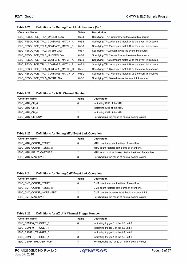
Table 6.21 Definitions for Setting Event Link Resource (2 / 3)
Constant Name Value Description
R01AN2600EJ0140 Rev.1.40 Page 19 of 57Jun. 07, 2018
RZ/T1 Group CMTW & ELC Sample Program
ELC_RESOURCE_TPU1_UNDERFLOW 0xB4 Specifying TPU1 underflow as the event link source
ELC_RESOURCE_TPU2_COMPARE_MATCH_A 0xB5 Specifying TPU2 compare match A as the event link source
ELC_RESOURCE_TPU2_COMPARE_MATCH_B 0xB6 Specifying TPU2 compare match B as the event link source
ELC_RESOURCE_TPU2_OVERFLOW 0xB7 Specifying TPU2 overflow as the event link source
ELC_RESOURCE_TPU2_UNDERFLOW 0xB8 Specifying TPU2 underflow as the event link source
ELC_RESOURCE_TPU3_COMPARE_MATCH_A 0xB9 Specifying TPU3 compare match A as the event link source
ELC_RESOURCE_TPU3_COMPARE_MATCH_B 0xBA Specifying TPU3 compare match B as the event link source
ELC_RESOURCE_TPU3_COMPARE_MATCH_C 0xBB Specifying TPU3 compare match C as the event link source
ELC_RESOURCE_TPU3_COMPARE_MATCH_D 0xBC Specifying TPU3 compare match D as the event link source
ELC_RESOURCE_TPU3_OVERFLOW 0xBD Specifying TPU3 overflow as the event link source
Table 6.22 Definitions for MTU Channel Number
Constant Name Value Description
ELC_MTU_CH_0 0 Indicating CH0 of the MTU
ELC_MTU_CH_3 1 Indicating CH1 of the MTU
ELC_MTU_CH_4 2 Indicating CH2 of the MTU
ELC_MTU_CH_NUM 3 For checking the range of normal setting values
Table 6.23 Definitions for Setting MTU Event Link Operation
Constant Name Value Description
ELC_MTU_COUNT_START 0 MTU count starts at the time of event link.
ELC_MTU_COUNT_RESTART 1 MTU count restarts at the time of event link.
ELC_MTU_INPUT_CAPTURE 2 MTU input capture is executed at the time of event link.
ELC_MTU_MAX_OVER 3 For checking the range of normal setting values
Table 6.24 Definitions for Setting CMT Event Link Operation
Constant Name Value Description
ELC_CMT_COUNT_START 0 CMT count starts at the time of event link.
ELC_CMT_COUNT_RESTART 1 CMT count restarts at the time of event link.
ELC_CMT_COUNT_INCREMENT 2 CMT counter increments at the time of event link.
ELC_CMT_MAX_OVER 3 For checking the range of normal setting values
Table 6.25 Definitions for ΔΣ Unit Channel Trigger Number
Constant Name Value Description
ELC_DSMIF0_TRIGGER_0 0 Indicating trigger 0 of the ΔΣ unit 0
ELC_DSMIF0_TRIGGER_1 1 Indicating trigger 0 of the ΔΣ unit 1
ELC_DSMIF1_TRIGGER_0 2 Indicating trigger 1 of the ΔΣ unit 0
ELC_DSMIF1_TRIGGER_1 3 Indicating trigger 1 of the ΔΣ unit 1
ELC_DSMIF_TRIGGER_NUM 4 For checking the range of normal setting values
Table 6.21 Definitions for Setting Event Link Resource (3 / 3)
Constant Name Value Description
R01AN2600EJ0140 Rev.1.40 Page 20 of 57Jun. 07, 2018
RZ/T1 Group CMTW & ELC Sample Program
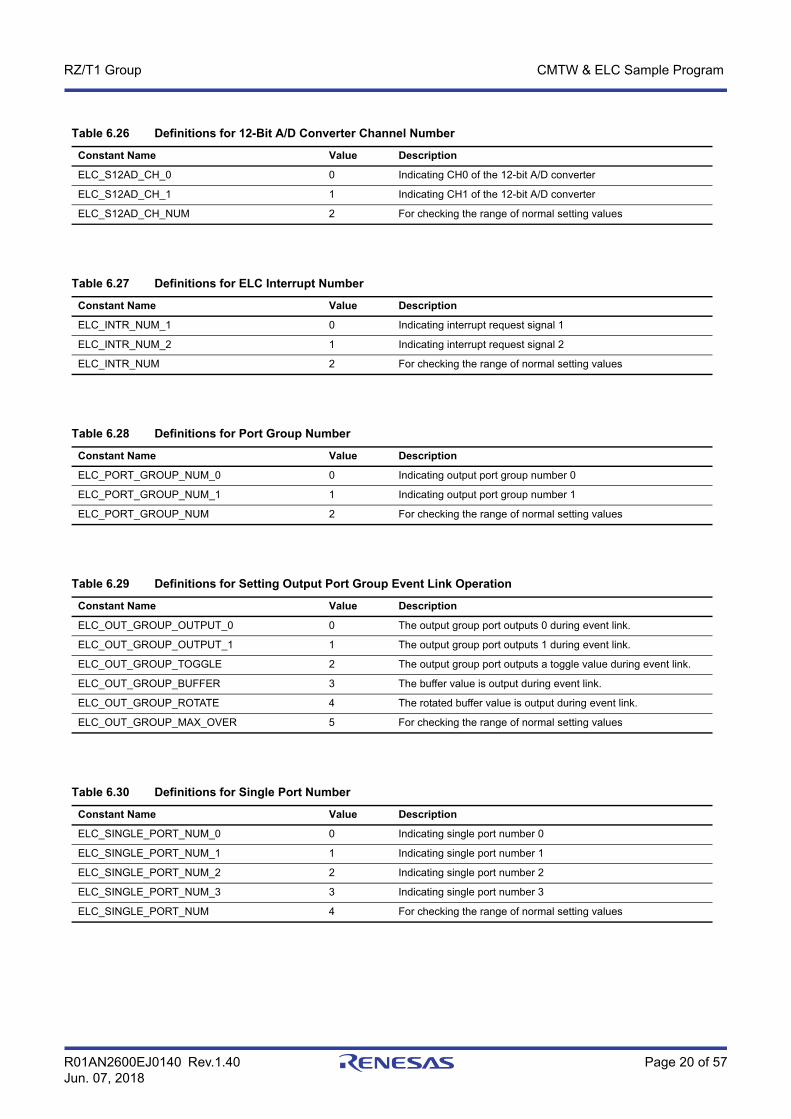
Table 6.26 Definitions for 12-Bit A/D Converter Channel Number
Constant Name Value Description
ELC_S12AD_CH_0 0 Indicating CH0 of the 12-bit A/D converter
ELC_S12AD_CH_1 1 Indicating CH1 of the 12-bit A/D converter
ELC_S12AD_CH_NUM 2 For checking the range of normal setting values
Table 6.27 Definitions for ELC Interrupt Number
Constant Name Value Description
ELC_INTR_NUM_1 0 Indicating interrupt request signal 1
ELC_INTR_NUM_2 1 Indicating interrupt request signal 2
ELC_INTR_NUM 2 For checking the range of normal setting values
Table 6.28 Definitions for Port Group Number
Constant Name Value Description
ELC_PORT_GROUP_NUM_0 0 Indicating output port group number 0
ELC_PORT_GROUP_NUM_1 1 Indicating output port group number 1
ELC_PORT_GROUP_NUM 2 For checking the range of normal setting values
Table 6.29 Definitions for Setting Output Port Group Event Link Operation
Constant Name Value Description
ELC_OUT_GROUP_OUTPUT_0 0 The output group port outputs 0 during event link.
ELC_OUT_GROUP_OUTPUT_1 1 The output group port outputs 1 during event link.
ELC_OUT_GROUP_TOGGLE 2 The output group port outputs a toggle value during event link.
ELC_OUT_GROUP_BUFFER 3 The buffer value is output during event link.
ELC_OUT_GROUP_ROTATE 4 The rotated buffer value is output during event link.
ELC_OUT_GROUP_MAX_OVER 5 For checking the range of normal setting values
Table 6.30 Definitions for Single Port Number
Constant Name Value Description
ELC_SINGLE_PORT_NUM_0 0 Indicating single port number 0
ELC_SINGLE_PORT_NUM_1 1 Indicating single port number 1
ELC_SINGLE_PORT_NUM_2 2 Indicating single port number 2
ELC_SINGLE_PORT_NUM_3 3 Indicating single port number 3
ELC_SINGLE_PORT_NUM 4 For checking the range of normal setting values

R01AN2600EJ0140 Rev.1.40 Page 21 of 57Jun. 07, 2018
RZ/T1 Group CMTW & ELC Sample Program
Table 6.31 Definitions for Setting Single Port Event Link Operation
Constant Name Value Description
ELC_SINGLE_PORT_OUTPUT_0 0 During event link, 0 is output.
ELC_SINGLE_PORT_OUTPUT_1 1 During event link, 1 is output.
ELC_SINGLE_PORT_TOGGLE 2 During event link, a toggle value is output.
ELC_SINGLE_PORT_ACTION_MAX_OVER 3 For checking the range of normal setting values
Table 6.32 Definitions for Setting CMTW Event Link Operation
Constant Name Value Description
ELC_CMTW_COUNT_START 0 CMTW count starts at the time of event link.
ELC_CMTW_COUNT_RESTART 1 CMTW count restarts at the time of event link.
ELC_CMTW_COUNT_INCREMENT 2 CMTW counter increments at the time of event link.
ELC_CMTW_COUNT_MAX_OVER 3 For checking the range of normal setting values
Table 6.33 Definitions for TPU Channel Number
Constant Name Value Description
ELC_TPU_CH_0 0 Indicating CH0 of the TPU.
ELC_TPU_CH_1 1 Indicating CH1 of the TPU.
ELC_TPU_CH_2 2 Indicating CH2 of the TPU.
ELC_TPU_CH_3 3 Indicating CH3 of the TPU.
ELC_TPU_CH_NUM 4 For checking the range of normal setting values
Table 6.34 Definitions for Setting TPU Event Link Operation
Constant Name Value Description
ELC_TPU_COUNT_START 0 TPU count starts at the time of event link.
ELC_TPU_COUNT_RESTART 1 TPU count restarts at the time of event link.
ELC_TPU_INPUT_CAPTURE 2 TPU input capture is executed at the time of event link.
ELC_TPU_MAX_OVER 3 For checking the range of normal setting values
Table 6.35 Definitions for GPT Channel Number
Constant Name Value Description
ELC_GPT_CH_0 0 Indicating CH0 of the GPT.
ELC_GPT_CH_1 1 Indicating CH1 of the GPT.
ELC_GPT_CH_2 2 Indicating CH2 of the GPT.
ELC_GPT_CH_3 3 Indicating CH3 of the GPT.
ELC_GPT_CH_NUM 4 For checking the range of normal setting values
R01AN2600EJ0140 Rev.1.40 Page 22 of 57Jun. 07, 2018
RZ/T1 Group CMTW & ELC Sample Program
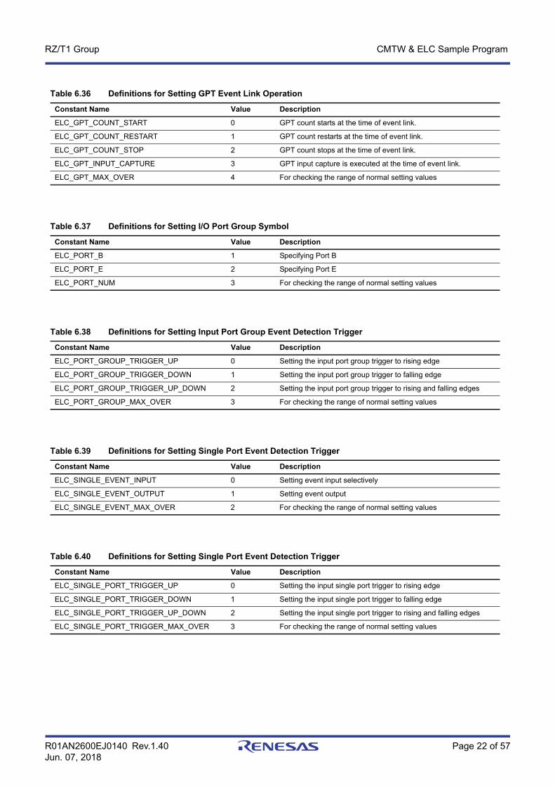
Table 6.36 Definitions for Setting GPT Event Link Operation
Constant Name Value Description
ELC_GPT_COUNT_START 0 GPT count starts at the time of event link.
ELC_GPT_COUNT_RESTART 1 GPT count restarts at the time of event link.
ELC_GPT_COUNT_STOP 2 GPT count stops at the time of event link.
ELC_GPT_INPUT_CAPTURE 3 GPT input capture is executed at the time of event link.
ELC_GPT_MAX_OVER 4 For checking the range of normal setting values
Table 6.37 Definitions for Setting I/O Port Group Symbol
Constant Name Value Description
ELC_PORT_B 1 Specifying Port B
ELC_PORT_E 2 Specifying Port E
ELC_PORT_NUM 3 For checking the range of normal setting values
Table 6.38 Definitions for Setting Input Port Group Event Detection Trigger
Constant Name Value Description
ELC_PORT_GROUP_TRIGGER_UP 0 Setting the input port group trigger to rising edge
ELC_PORT_GROUP_TRIGGER_DOWN 1 Setting the input port group trigger to falling edge
ELC_PORT_GROUP_TRIGGER_UP_DOWN 2 Setting the input port group trigger to rising and falling edges
ELC_PORT_GROUP_MAX_OVER 3 For checking the range of normal setting values
Table 6.39 Definitions for Setting Single Port Event Detection Trigger
Constant Name Value Description
ELC_SINGLE_EVENT_INPUT 0 Setting event input selectively
ELC_SINGLE_EVENT_OUTPUT 1 Setting event output
ELC_SINGLE_EVENT_MAX_OVER 2 For checking the range of normal setting values
Table 6.40 Definitions for Setting Single Port Event Detection Trigger
Constant Name Value Description
ELC_SINGLE_PORT_TRIGGER_UP 0 Setting the input single port trigger to rising edge
ELC_SINGLE_PORT_TRIGGER_DOWN 1 Setting the input single port trigger to falling edge
ELC_SINGLE_PORT_TRIGGER_UP_DOWN 2 Setting the input single port trigger to rising and falling edges
ELC_SINGLE_PORT_TRIGGER_MAX_OVER 3 For checking the range of normal setting values
R01AN2600EJ0140 Rev.1.40 Page 23 of 57Jun. 07, 2018
RZ/T1 Group CMTW & ELC Sample Program
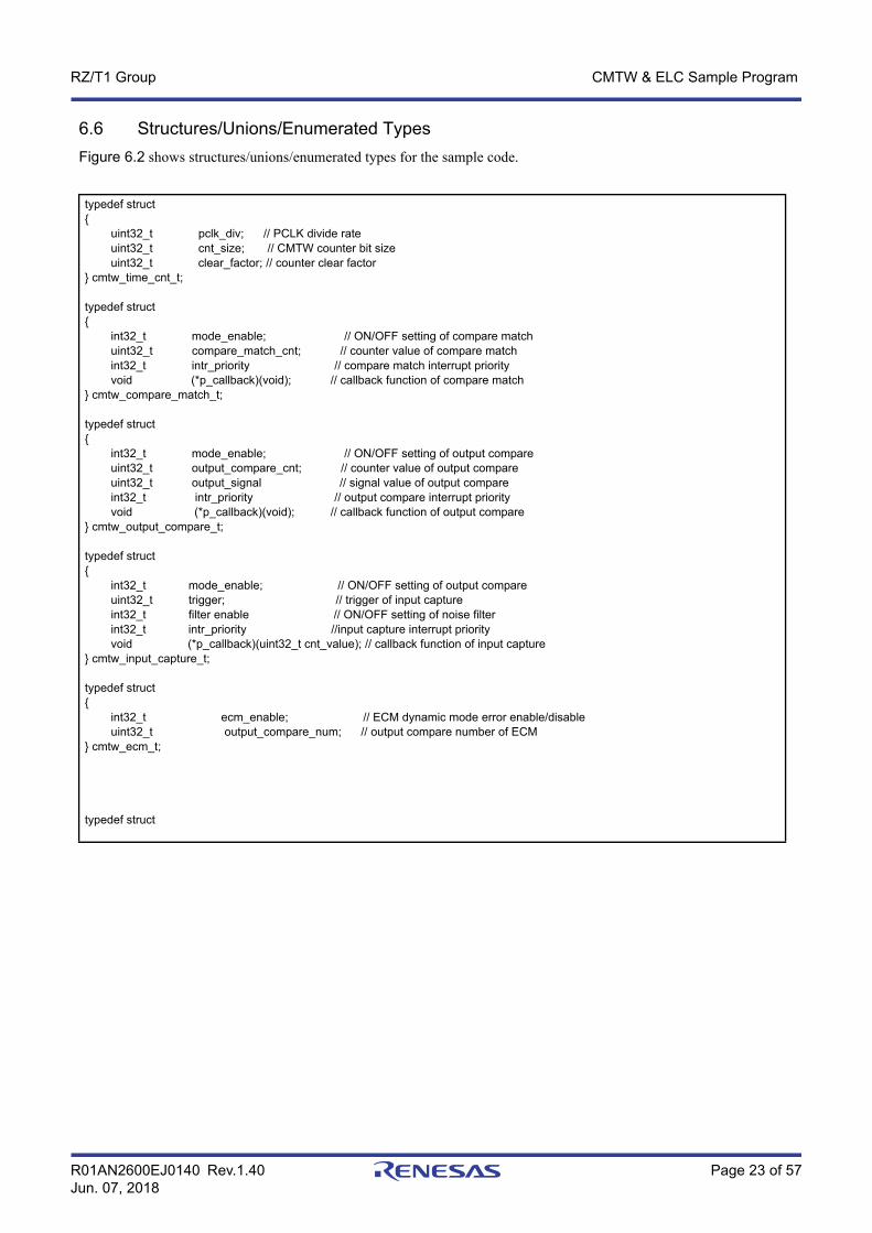
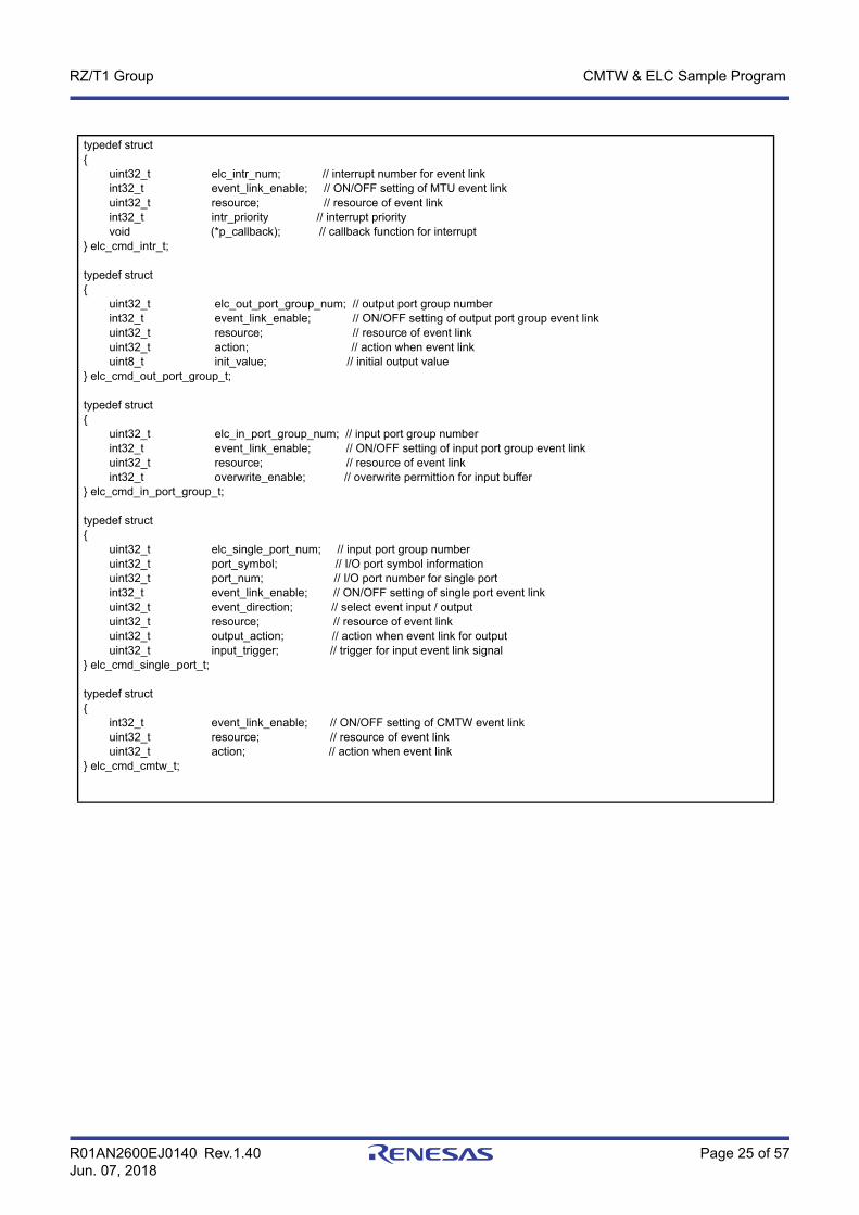
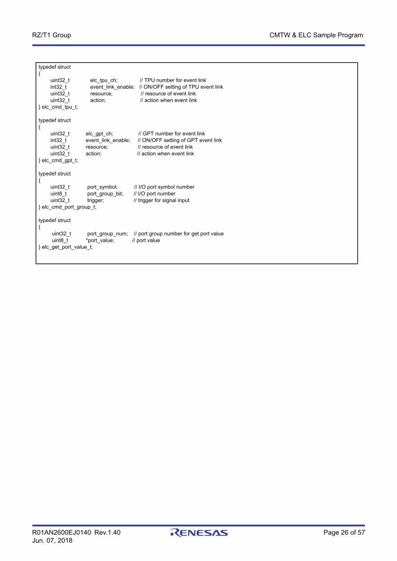
6.6 Structures/Unions/Enumerated TypesFigure 6.2 shows structures/unions/enumerated types for the sample code.
typedef struct{ uint32_t pclk_div; // PCLK divide rate uint32_t cnt_size; // CMTW counter bit size uint32_t clear_factor; // counter clear factor} cmtw_time_cnt_t;
typedef struct { int32_t mode_enable; // ON/OFF setting of compare match uint32_t compare_match_cnt; // counter value of compare match int32_t intr_priority // compare match interrupt priority void (*p_callback)(void); // callback function of compare match} cmtw_compare_match_t;
typedef struct { int32_t mode_enable; // ON/OFF setting of output compare uint32_t output_compare_cnt; // counter value of output compare uint32_t output_signal // signal value of output compare int32_t intr_priority // output compare interrupt priority void (*p_callback)(void); // callback function of output compare} cmtw_output_compare_t;
typedef struct { int32_t mode_enable; // ON/OFF setting of output compare uint32_t trigger; // trigger of input capture int32_t filter enable // ON/OFF setting of noise filter int32_t intr_priority //input capture interrupt priority void (*p_callback)(uint32_t cnt_value); // callback function of input capture} cmtw_input_capture_t;
typedef struct{ int32_t ecm_enable; // ECM dynamic mode error enable/disable uint32_t output_compare_num; // output compare number of ECM} cmtw_ecm_t;
typedef struct

R01AN2600EJ0140 Rev.1.40 Page 24 of 57Jun. 07, 2018
RZ/T1 Group CMTW & ELC Sample Program
{ cmtw_compare_match_t compare_match; // setting of compare match cmtw_output_compare_t output_compare[CMTW_OUTPUT_COMPARE_NUM_MAX]; // setting of output compare cmtw_input_capture_t input_capture[CMTW_INPUT_CAPTURE_NUM_MAX]; // setting of input capture uint32_t noise_filter_clk // noise filter setting of input capture} cmtw_mode_t;
typedef struct { cmtw_time_cnt_t time_cnt_param; // setting of timer count cmtw_mode_t mode_param; // setting of CMTW mode} cmtw_cfg_t;
typedef struct{ uint32_t elc_mtu_ch; // MTU number for event link int32_t event_link_enable; // ON/OFF setting of MTU event link uint32_t resource; // resource of event link uint32_t action; // action when event link} elc_cmd_mtu_t;
typedef struct{ int32_t event_link_enable; // ON/OFF setting of CMT event link uint32_t resource; // resource of event link uint32_t action; // action when event link} elc_cmd_cmt_t;
typedef struct{ uint32_t elc_dsmif_ch; // DSMIF number for event link int32_t event_link_enable; // ON/OFF setting of DSMIF event link uint32_t resource; // resource of event link} elc_cmd_dsmif_t;
typedef struct{ uint32_t elc_s12ad_ch; // S12AD number for event link int32_t event_link_enable; // ON/OFF setting of S12AD event link uint32_t resource; // resource of event link} elc_cmd_s12ad_t;
R01AN2600EJ0140 Rev.1.40 Page 25 of 57Jun. 07, 2018
RZ/T1 Group CMTW & ELC Sample Program
typedef struct{ uint32_t elc_intr_num; // interrupt number for event link int32_t event_link_enable; // ON/OFF setting of MTU event link uint32_t resource; // resource of event link int32_t intr_priority // interrupt priority void (*p_callback); // callback function for interrupt} elc_cmd_intr_t;
typedef struct{ uint32_t elc_out_port_group_num; // output port group number int32_t event_link_enable; // ON/OFF setting of output port group event link uint32_t resource; // resource of event link uint32_t action; // action when event link uint8_t init_value; // initial output value} elc_cmd_out_port_group_t;
typedef struct{ uint32_t elc_in_port_group_num; // input port group number int32_t event_link_enable; // ON/OFF setting of input port group event link uint32_t resource; // resource of event link int32_t overwrite_enable; // overwrite permittion for input buffer } elc_cmd_in_port_group_t;
typedef struct{ uint32_t elc_single_port_num; // input port group number uint32_t port_symbol; // I/O port symbol information uint32_t port_num; // I/O port number for single port int32_t event_link_enable; // ON/OFF setting of single port event link uint32_t event_direction; // select event input / output uint32_t resource; // resource of event link uint32_t output_action; // action when event link for output uint32_t input_trigger; // trigger for input event link signal} elc_cmd_single_port_t;
typedef struct{ int32_t event_link_enable; // ON/OFF setting of CMTW event link uint32_t resource; // resource of event link uint32_t action; // action when event link} elc_cmd_cmtw_t;
R01AN2600EJ0140 Rev.1.40 Page 26 of 57Jun. 07, 2018
RZ/T1 Group CMTW & ELC Sample Program
typedef struct{ uint32_t elc_tpu_ch; // TPU number for event link int32_t event_link_enable; // ON/OFF setting of TPU event link uint32_t resource; // resource of event link uint32_t action; // action when event link} elc_cmd_tpu_t;
typedef struct{ uint32_t elc_gpt_ch; // GPT number for event link int32_t event_link_enable; // ON/OFF setting of GPT event link uint32_t resource; // resource of event link uint32_t action; // action when event link} elc_cmd_gpt_t;
typedef struct{ uint32_t port_symbol; // I/O port symbol number uint8_t port_group_bit; // I/O port number uint32_t trigger; // trigger for signal input} elc_cmd_port_group_t;
typedef struct{ uint32_t port_group_num; // port group number for get port value uint8_t *port_value; // port value } elc_get_port_value_t;

R01AN2600EJ0140 Rev.1.40 Page 27 of 57Jun. 07, 2018
RZ/T1 Group CMTW & ELC Sample Program
typedef enum /* CMTW error codes */{ CMTW_SUCCESS = 0, CMTW_ERR_INVALID_CH = 1, CMTW_ERR_INVALID_ARG = 2, CMTW_ERR_NOT_OPENED = 3, CMTW_ERR_NOT_CLOSED = 4, CMTW_ERR_TIMER_RUNNING = 5, CMTW_ERR_TIMER_STOP = 6, CMTW_ERR_MISSING_PTR = 7} cmtw_err_t;
typedef enum /* ELC error codes */{ ELC_SUCCESS = 0, ELC_ERR_INVALID_ARG = 1, ELC_ERR_NOT_OPENED = 2, ELC_ERR_NOT_CLOSED = 3, ELC_ERR_MISSING_PTR = 4} elc_err_t;
Figure 6.2 Structures/Unions/Enumerated Types for the Sample Code
R01AN2600EJ0140 Rev.1.40 Page 28 of 57Jun. 07, 2018
RZ/T1 Group CMTW & ELC Sample Program
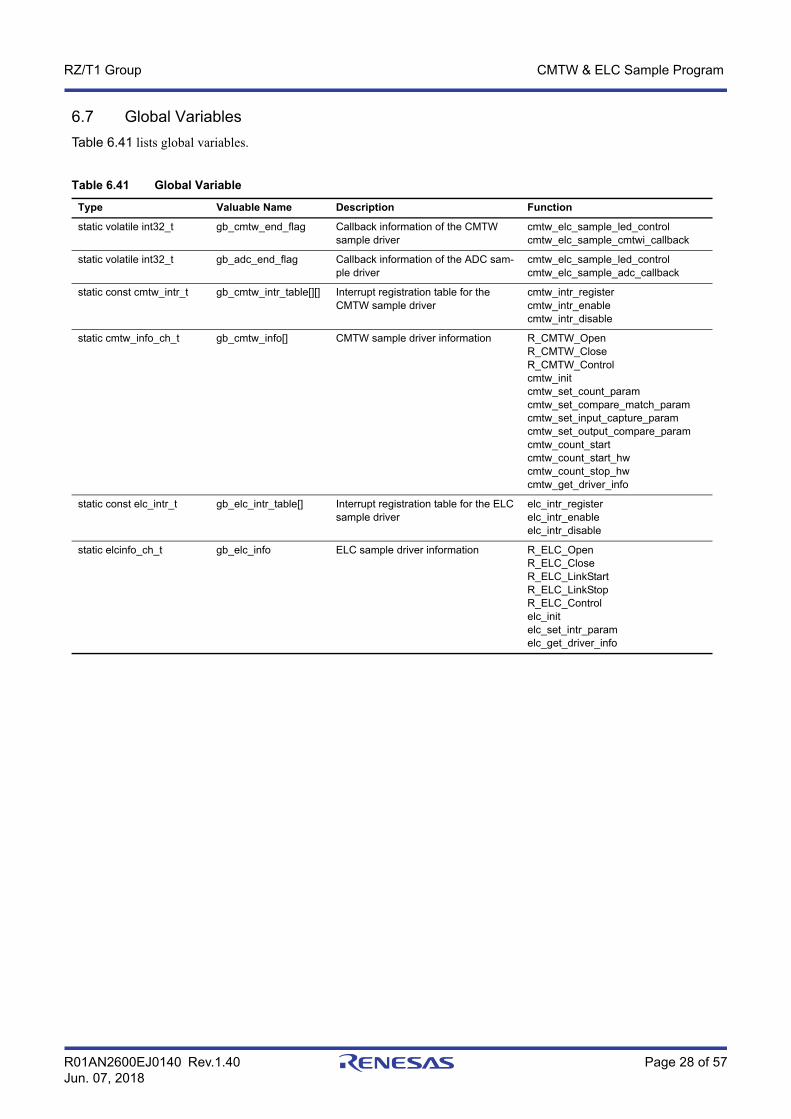
6.7 Global VariablesTable 6.41 lists global variables.
Table 6.41 Global Variable
Type Valuable Name Description Function
static volatile int32_t gb_cmtw_end_flag Callback information of the CMTW sample driver
cmtw_elc_sample_led_controlcmtw_elc_sample_cmtwi_callback
static volatile int32_t gb_adc_end_flag Callback information of the ADC sam-ple driver
cmtw_elc_sample_led_controlcmtw_elc_sample_adc_callback
static const cmtw_intr_t gb_cmtw_intr_table[][] Interrupt registration table for the CMTW sample driver
cmtw_intr_registercmtw_intr_enablecmtw_intr_disable
static cmtw_info_ch_t gb_cmtw_info[] CMTW sample driver information R_CMTW_OpenR_CMTW_CloseR_CMTW_Controlcmtw_initcmtw_set_count_paramcmtw_set_compare_match_paramcmtw_set_input_capture_paramcmtw_set_output_compare_paramcmtw_count_startcmtw_count_start_hwcmtw_count_stop_hwcmtw_get_driver_info
static const elc_intr_t gb_elc_intr_table[] Interrupt registration table for the ELC sample driver
elc_intr_registerelc_intr_enableelc_intr_disable
static elcinfo_ch_t gb_elc_info ELC sample driver information R_ELC_OpenR_ELC_CloseR_ELC_LinkStartR_ELC_LinkStopR_ELC_Controlelc_initelc_set_intr_paramelc_get_driver_info
R01AN2600EJ0140 Rev.1.40 Page 29 of 57Jun. 07, 2018
RZ/T1 Group CMTW & ELC Sample Program
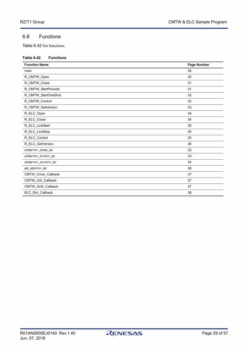
6.8 Functions
Table 6.42 list functions.
Table 6.42 Functions
Function Name Page Number
main 36
R_CMTW_Open 30
R_CMTW_Close 31
R_CMTW_StartPeriodic 31
R_CMTW_StartOneShot 32
R_CMTW_Control 32
R_CMTW_GetVersion 33
R_ELC_Open 34
R_ELC_Close 34
R_ELC_LinkStart 35
R_ELC_LinkStop 35
R_ELC_Control 35
R_ELC_GetVersion 36
cmtw<n>_cmwi_isr 33
cmtw<n>_ic<m>i_isr 33
cmtw<n>_oc<m>i_isr 34
elc_elci<n>_isr 36
CMTW_Cmwi_Callback 37
CMTW_Ic0i_Callback 37
CMTW_Oc0i_Callback 37
ELC_Elci_Callback 38
R01AN2600EJ0140 Rev.1.40 Page 30 of 57Jun. 07, 2018
RZ/T1 Group CMTW & ELC Sample Program
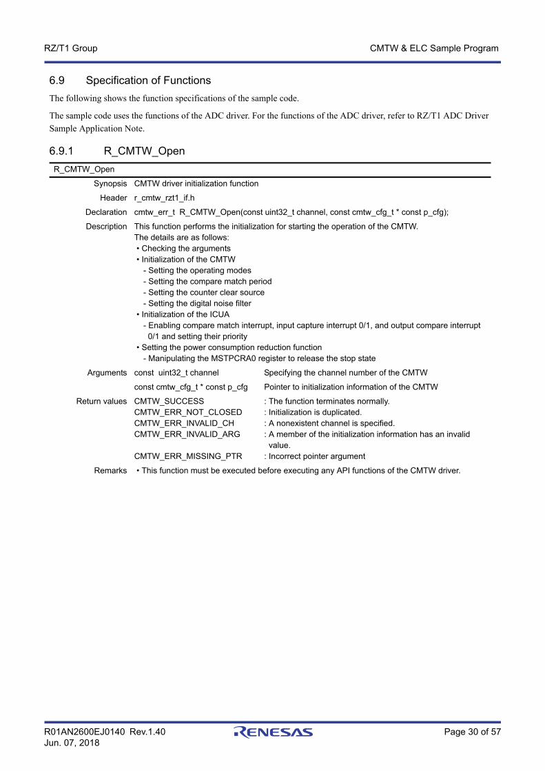
6.9 Specification of FunctionsThe following shows the function specifications of the sample code.
The sample code uses the functions of the ADC driver. For the functions of the ADC driver, refer to RZ/T1 ADC Driver Sample Application Note.
6.9.1 R_CMTW_OpenR_CMTW_Open
Synopsis CMTW driver initialization function
Header r_cmtw_rzt1_if.h
Declaration cmtw_err_t R_CMTW_Open(const uint32_t channel, const cmtw_cfg_t * const p_cfg);
Description This function performs the initialization for starting the operation of the CMTW. The details are as follows: • Checking the arguments • Initialization of the CMTW - Setting the operating modes - Setting the compare match period - Setting the counter clear source - Setting the digital noise filter • Initialization of the ICUA - Enabling compare match interrupt, input capture interrupt 0/1, and output compare interrupt 0/1 and setting their priority • Setting the power consumption reduction function - Manipulating the MSTPCRA0 register to release the stop state
Arguments const uint32_t channel Specifying the channel number of the CMTW
const cmtw_cfg_t * const p_cfg Pointer to initialization information of the CMTW
Return values CMTW_SUCCESSCMTW_ERR_NOT_CLOSEDCMTW_ERR_INVALID_CHCMTW_ERR_INVALID_ARG
CMTW_ERR_MISSING_PTR
: The function terminates normally.: Initialization is duplicated.: A nonexistent channel is specified.: A member of the initialization information has an invalid value.: Incorrect pointer argument
Remarks • This function must be executed before executing any API functions of the CMTW driver.

R01AN2600EJ0140 Rev.1.40 Page 31 of 57Jun. 07, 2018
RZ/T1 Group CMTW & ELC Sample Program
6.9.2 R_CMTW_Close
6.9.3 R_CMTW_StartPeriodic
R_CMTW_Close
Synopsis End processing function of the CMTW driver
Header r_cmtw_rzt1_if.h
Declaration cmtw_err_t R_CMTW_Close(const uint32_t channel);
Description This function handles processing for terminating the operation of the CMTW.The details are as follows: • End processing of the ICUA - Disabling compare match interrupt, input capture interrupt 0/1, and output compare interrupt 0/1 • End processing of the CMTW - Stopping the timer counter • Setting the power consumption reduction function - Manipulating the MSTPCRA0 register to set the stop state
Arguments const uint32_t channel Specifying the channel number of the CMTW
Return values CMTW_SUCCESSCMTW_ERR_INVALID_CH
: The function terminates normally.: A nonexistent channel is specified.
Remarks • This function must be executed after executing R_CMTW_Open.
R_CmMTW_Start_Periodic
Synopsis Timer counter periodic operation start function
Header r_cmtw_rzt1_if.h
Declaration cmtw_err_t R_CMTW_StartPeriodic(const uint32_t channel);
Description This function starts a periodic operation of timer counting.
Arguments const uint32_t channel Specifying the channel number of the CMTW.
Return values CMTW_SUCCESSCMTW_ERR_NOT_OPENEDCMTW_ERR_INVALID_CHCMTW_ERR_TIMER_RUNNING
: The function terminates normally.: The function is executed in an uninitialized state.: A nonexistent channel is specified.: The function is executed while the timer counter is running.
Remarks • This function must be executed after executing R_CMTW_Open. • Call R_CMTW_Close() to stop periodic operations.
R01AN2600EJ0140 Rev.1.40 Page 32 of 57Jun. 07, 2018
RZ/T1 Group CMTW & ELC Sample Program
6.9.4 R_CMTW_StartOneShot
6.9.5 R_CMTW_Control
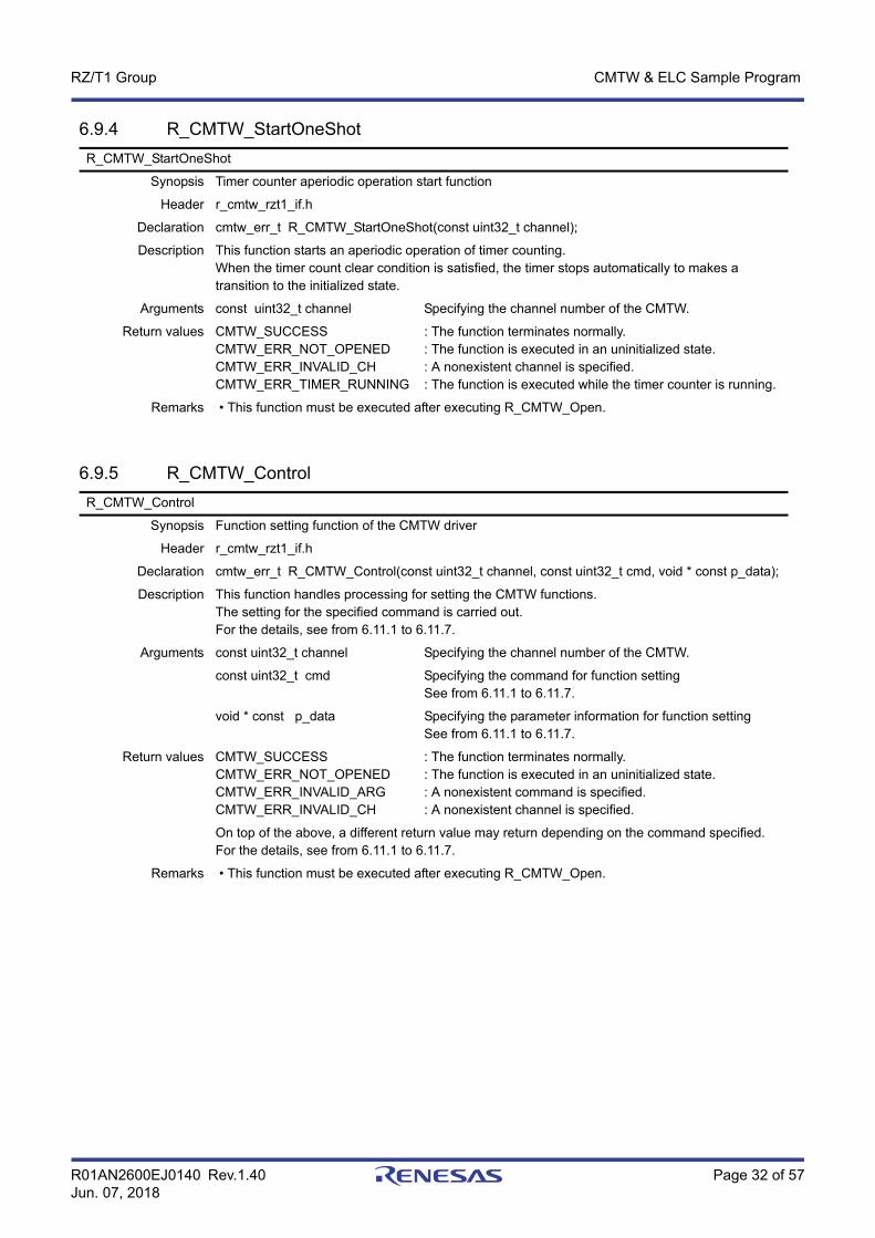
R_CMTW_StartOneShot
Synopsis Timer counter aperiodic operation start function
Header r_cmtw_rzt1_if.h
Declaration cmtw_err_t R_CMTW_StartOneShot(const uint32_t channel);
Description This function starts an aperiodic operation of timer counting. When the timer count clear condition is satisfied, the timer stops automatically to makes a transition to the initialized state.
Arguments const uint32_t channel Specifying the channel number of the CMTW.
Return values CMTW_SUCCESSCMTW_ERR_NOT_OPENEDCMTW_ERR_INVALID_CHCMTW_ERR_TIMER_RUNNING
: The function terminates normally.: The function is executed in an uninitialized state.: A nonexistent channel is specified.: The function is executed while the timer counter is running.
Remarks • This function must be executed after executing R_CMTW_Open.
R_CMTW_Control
Synopsis Function setting function of the CMTW driver
Header r_cmtw_rzt1_if.h
Declaration cmtw_err_t R_CMTW_Control(const uint32_t channel, const uint32_t cmd, void * const p_data);
Description This function handles processing for setting the CMTW functions.The setting for the specified command is carried out. For the details, see from 6.11.1 to 6.11.7.
Arguments const uint32_t channel Specifying the channel number of the CMTW.
const uint32_t cmd Specifying the command for function settingSee from 6.11.1 to 6.11.7.
void * const p_data Specifying the parameter information for function settingSee from 6.11.1 to 6.11.7.
Return values CMTW_SUCCESSCMTW_ERR_NOT_OPENEDCMTW_ERR_INVALID_ARGCMTW_ERR_INVALID_CH
: The function terminates normally.: The function is executed in an uninitialized state.: A nonexistent command is specified.: A nonexistent channel is specified.
On top of the above, a different return value may return depending on the command specified. For the details, see from 6.11.1 to 6.11.7.
Remarks • This function must be executed after executing R_CMTW_Open.

R01AN2600EJ0140 Rev.1.40 Page 33 of 57Jun. 07, 2018
RZ/T1 Group CMTW & ELC Sample Program
6.9.6 R_CMTW_GetVersion
6.9.7 cmtw<n>_cmwi_isr
6.9.8 cmtw<n>_ic<m>i_isr
R_CMTW_GetVersion
Synopsis Acquisition function of the CMTW driver version information
Header
Declaration uint32_t R_CMTW_GetVersion(void);
Description This function acquires the version information of the CMTW driver.
Arguments None
Return values Encoded version information: 0-15bit Minor Version: 16-31bit Major Version
Remarks –
cmtw<n>_cmwi_isr
Synopsis CMTW channel <n> compare match interrupt handler (n = 0, 1)
Header –
Declaration void cmtw<n>_cmwi_isr ( void );
Description This function calls a compare match callback function that has been registered by using the R_CMTW_Open() or R_CMTW_Control() function.It also specifies compare match as the timer clear source and, when an aperiodic operation is running, stops the timer to make a transition to the initialized state.
Arguments None
Return values None
cmtw<n>_ic<m>i_isr
Synopsis CMTW channel <n> input capture <m> interrupt handler (n = 0, 1; m = 0, 1)
Header –
Declaration void cmtw<n>_ic<m>i_isr ( void );
Description This function calls an input capture callback function that has been registered by using the R_CMTW_Open() or R_CMTW_Control() function. It also specifies input capture as the timer clear source and, when an aperiodic operation is running, stops the timer to make a transition to the initialized state.
Arguments None
Return values None

R01AN2600EJ0140 Rev.1.40 Page 34 of 57Jun. 07, 2018
RZ/T1 Group CMTW & ELC Sample Program
6.9.9 cmtw<n>_oc<m>i_isr
6.9.10 R_ELC_Open
6.9.11 R_ELC_Close
cmtw<n>_oc<m>i_isr
Synopsis CMTW channel <n> output compare <m> interrupt handler (n = 0, 1; m = 0, 1)
Header –
Declaration void cmtw<n>_oc<m>i_isr ( void );
Description This function calls an output compare callback function that has been registered by using the R_CMTW_Open() or R_CMTW_Control() function.It also specifies output compare as the timer clear source and, when an aperiodic operation is running, stops the timer to make a transition to the initialized state.
Arguments None
Return values None
R_ELC_Open
Synopsis ELC driver initialization function
Header r_elc_rzt1_if.h
Declaration elc_err_t R_ELC_Open(void);
Description This function performs the initialization for starting the operation of the ELC. The details are as follows: • Setting the power consumption reduction function - Manipulating the MSTPCRC6 register to release the stop state
Arguments None
Return values ELC_SUCCESSELC_ERR_NOT_CLOSED
: The function terminates normally.: Initialization is duplicated.
Remarks • This function must be executed before executing any API functions of the ELC driver.
R_ELC_Close
Synopsis End processing function of the ELC driver
Header r_elc_rzt1_if.h
Declaration void R_ELC_Close(void);
Description This function handles processing for terminating the operation of the ELC.The details are as follows: • End processing of the ICUA - Disabling input request signals 1 and 2 • End processing of the ELC - Disabling the ELC function • Setting the power consumption reduction function - Manipulating the MSTPCRC6 register to set the stop state
Arguments None
Return values None
Remarks • This function must be executed after executing R_ELC_Open.
R01AN2600EJ0140 Rev.1.40 Page 35 of 57Jun. 07, 2018
RZ/T1 Group CMTW & ELC Sample Program
6.9.12 R_ELC_LinkStart
6.9.13 R_ELC_LinkStop
6.9.14 R_ELC_Control
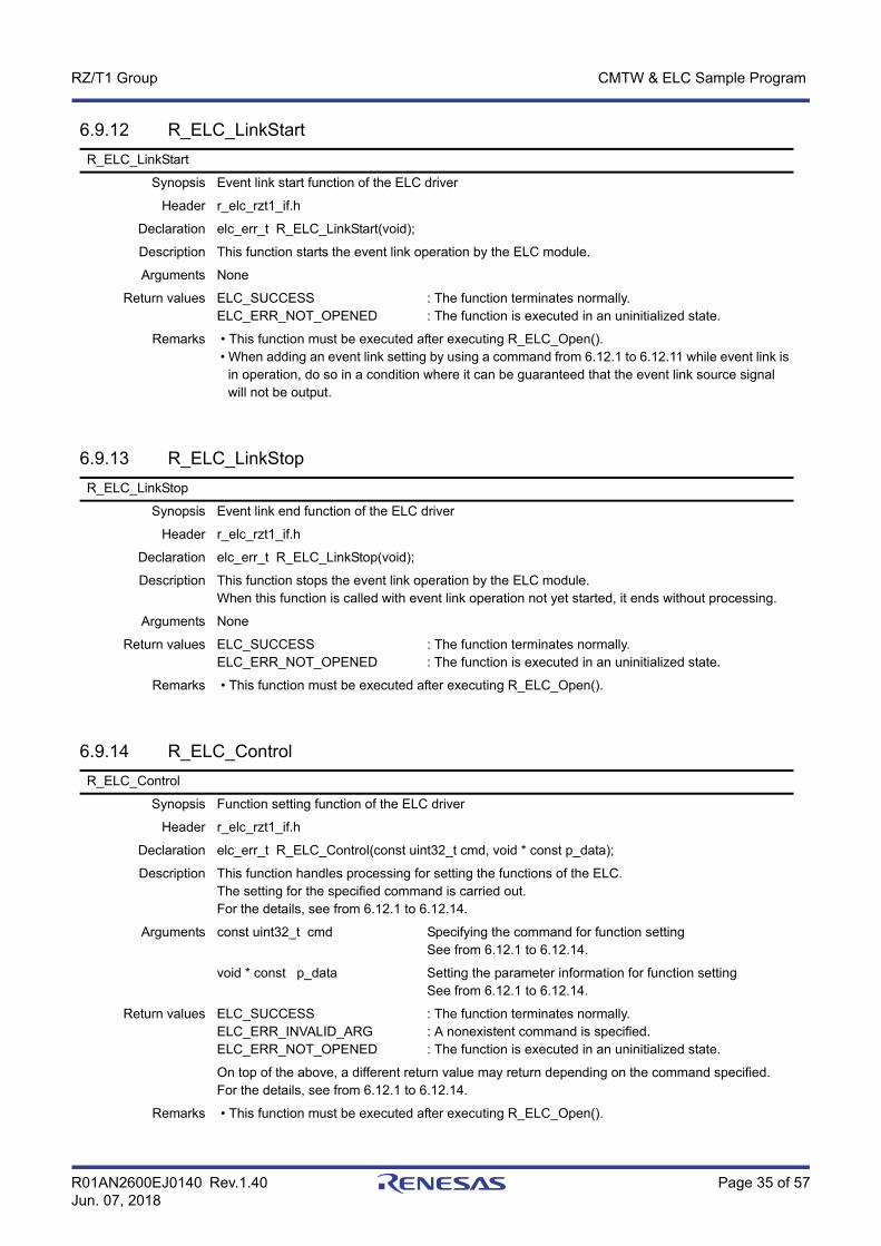
R_ELC_LinkStart
Synopsis Event link start function of the ELC driver
Header r_elc_rzt1_if.h
Declaration elc_err_t R_ELC_LinkStart(void);
Description This function starts the event link operation by the ELC module.
Arguments None
Return values ELC_SUCCESSELC_ERR_NOT_OPENED
: The function terminates normally.: The function is executed in an uninitialized state.
Remarks • This function must be executed after executing R_ELC_Open(). • When adding an event link setting by using a command from 6.12.1 to 6.12.11 while event link is in operation, do so in a condition where it can be guaranteed that the event link source signal will not be output.
R_ELC_LinkStop
Synopsis Event link end function of the ELC driver
Header r_elc_rzt1_if.h
Declaration elc_err_t R_ELC_LinkStop(void);
Description This function stops the event link operation by the ELC module. When this function is called with event link operation not yet started, it ends without processing.
Arguments None
Return values ELC_SUCCESSELC_ERR_NOT_OPENED
: The function terminates normally.: The function is executed in an uninitialized state.
Remarks • This function must be executed after executing R_ELC_Open().
R_ELC_Control
Synopsis Function setting function of the ELC driver
Header r_elc_rzt1_if.h
Declaration elc_err_t R_ELC_Control(const uint32_t cmd, void * const p_data);
Description This function handles processing for setting the functions of the ELC.The setting for the specified command is carried out. For the details, see from 6.12.1 to 6.12.14.
Arguments const uint32_t cmd Specifying the command for function settingSee from 6.12.1 to 6.12.14.
void * const p_data Setting the parameter information for function settingSee from 6.12.1 to 6.12.14.
Return values ELC_SUCCESSELC_ERR_INVALID_ARGELC_ERR_NOT_OPENED
: The function terminates normally.: A nonexistent command is specified.: The function is executed in an uninitialized state.
On top of the above, a different return value may return depending on the command specified. For the details, see from 6.12.1 to 6.12.14.
Remarks • This function must be executed after executing R_ELC_Open().

R01AN2600EJ0140 Rev.1.40 Page 36 of 57Jun. 07, 2018
RZ/T1 Group CMTW & ELC Sample Program
6.9.15 R_ELC_GetVersion
6.9.16 elc_elci<n>_isr
6.9.17 main
R_ELC_GetVersion
Synopsis Acquisition function of the ELC driver version information
Header
Declaration uint32_t R_ELC_GetVersion(void);
Description This function acquires the version information of the ELC driver.
Arguments None
Return values Encoded version information: 0-15bit Minor Version: 16-31bit Major Version
Remarks –
elc_elci<n>_isr
Synopsis ELC event link interrupt handler (n = 1, 2)
Header –
Declaration void elc_elci<n>_isr ( void );
Description This function calls a callback function that has been registered by using the R_ELC_Open() or R_ELC_Control() function.
Arguments None
Return values None
main
Synopsis This function performs the A/D conversion of the input voltage to the potentiometer periodically.
Header –
Declaration int32_t main(void);
Description This function handles the following processing. The CMTW0 is linked with the ADC by the ELC. At intervals of compare match of the CMTW0, the A/D conversion results of the input voltage to the potentiometer that is connected on the evaluation board are classified into five scales and displayed by using the LEDs on the evaluation board that are assigned to each of the scales as follows. This program terminates if a result exceeds the fourth classification level.
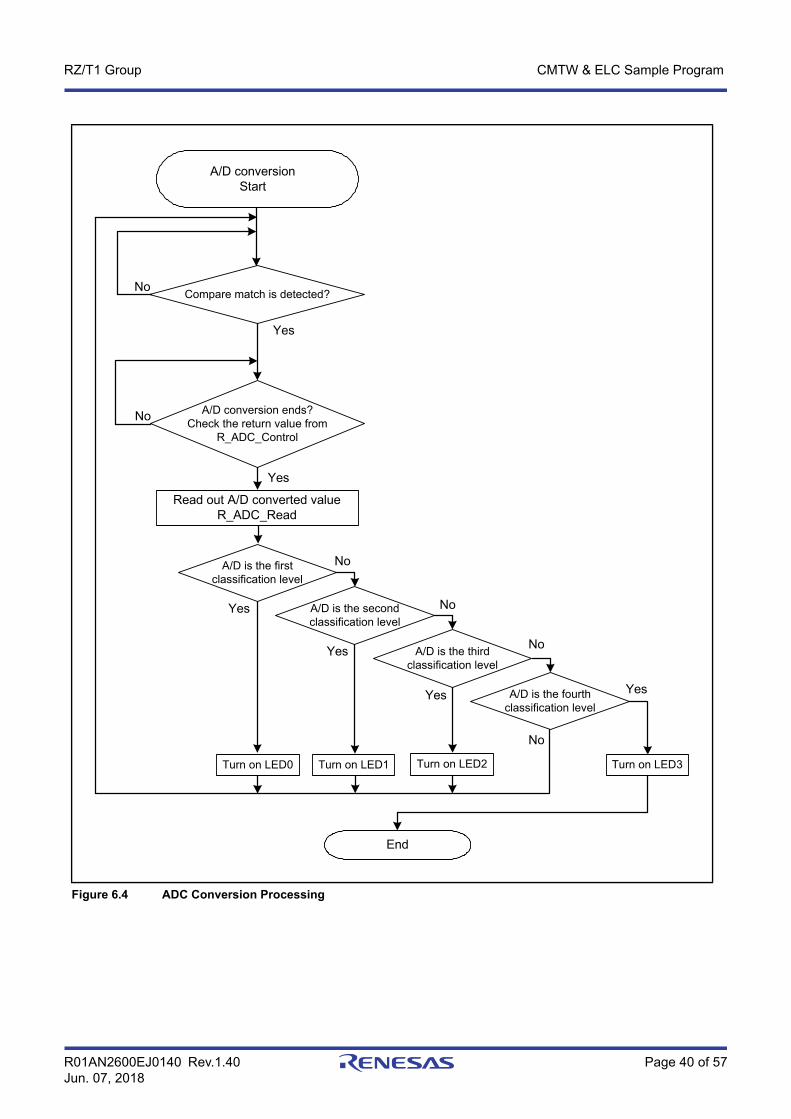
A/D conversion level is from ADC_LVL0 to ADC_LVL1 (first classification level): LED 0 turns on. A/D conversion level is from ADC_LVL1 to ADC_LVL2 (second classification level): LED 1 turns on. A/D conversion level is from ADC_LVL2 to ADC_LVL3 (third classification level): LED 2 turns on. A/D conversion level is from ADC_LVL3 to ADC_LVL4 (fourth classification level): LED 3 turns on. A/D conversion level is ADC_LVL4 or greater: The program terminates.
Arguments None
Return values None
Remarks • The ADC driver starts up in the synchronous trigger and single scan mode.

R01AN2600EJ0140 Rev.1.40 Page 37 of 57Jun. 07, 2018
RZ/T1 Group CMTW & ELC Sample Program
6.9.18 CMTW_Cmwi_Callback
6.9.19 CMTW_Ic0i_Callback
6.9.20 CMTW_Oc0i_Callback
CMTW_Cmwi_Callback
Synopsis CMTW sample program compare match callback function
Header –
Declaration void CMTW_Cmwi_Callback(void);
Description This function is a callback function to notify the occurrence of a compare match interrupt of the CMTW.
Arguments None
Return values None
Remarks • The function name is just an example to register the function to the driver. There is no restriction for the name. • In the sample program, this function is used in the function name of CMTW_Sample_Callback.
CMTW_Ic0i_Callback
Synopsis CMTW sample program input capture callback function
Header –
Declaration void CMTW_Ic0i_Callback(uint32_t cnt_value);
Description This function is a callback function to notify the occurrence of an input capture interrupt of the CMTW. The counter value at the time of an input capture is passed as the argument.
Arguments uint32_t cnt_value Counter value when an input capture occurs
Return values None
Remarks • The function name is just an example to register the function to the driver. There is no restriction for the name. • Not used in the sample program.
CMTW_Oc0i_Callback
Synopsis CMTW output compare callback function
Header –
Declaration void CMTW_Oc0i_Callback(void);
Description This function is a callback function to notify the occurrence of an output compare interrupt of the CMTW.
Arguments None
Return values None
Remarks • The function name is just an example to register the function to the driver. There is no restriction for the name. • Not used in the sample program.

R01AN2600EJ0140 Rev.1.40 Page 38 of 57Jun. 07, 2018
RZ/T1 Group CMTW & ELC Sample Program
6.9.21 ELC_Elci_CallbackELC_Elci_Callback
Synopsis ELC event link callback function
Header –
Declaration void ELC_Elci_Callback(void);
Description This function is a callback function to notify the occurrence of an event link interrupt of the ELC.
Arguments None
Return values None
Remarks • The function name is just an example to register the function to the driver. There is no restriction for the name. • Not used in the sample program.
R01AN2600EJ0140 Rev.1.40 Page 39 of 57Jun. 07, 2018
RZ/T1 Group CMTW & ELC Sample Program
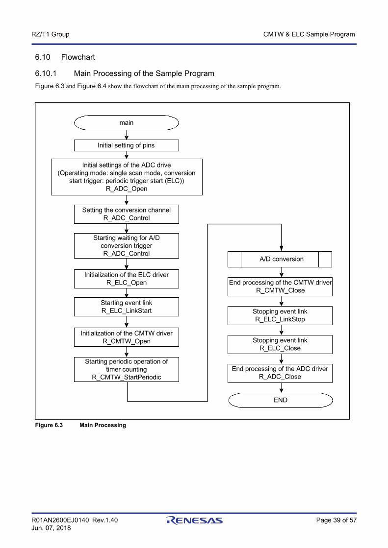
6.10 Flowchart
6.10.1 Main Processing of the Sample ProgramFigure 6.3 and Figure 6.4 show the flowchart of the main processing of the sample program.
Figure 6.3 Main Processing
main
Initial setting of pins
Initial settings of the ADC drive(Operating mode: single scan mode, conversion
start trigger: periodic trigger start (ELC)) R_ADC_Open
Setting the conversion channel R_ADC_Control
Starting waiting for A/D conversion triggerR_ADC_Control
Initialization of the CMTW driver R_CMTW_Open
Initialization of the ELC driver R_ELC_Open
Starting event link R_ELC_LinkStart
Starting periodic operation of timer counting
R_CMTW_StartPeriodic
END
A/D conversion
End processing of the ADC driver R_ADC_Close
End processing of the CMTW driver R_CMTW_Close
Stopping event link R_ELC_LinkStop
Stopping event linkR_ELC_Close
R01AN2600EJ0140 Rev.1.40 Page 40 of 57Jun. 07, 2018
RZ/T1 Group CMTW & ELC Sample Program
Figure 6.4 ADC Conversion Processing
A/D conversionStart
A/D conversion ends? Check the return value from
R_ADC_Control
Read out A/D converted value R_ADC_Read
A/D is the first classification level
No
No
Turn on LED0 Turn on LED2
Compare match is detected?No
Yes
End
No
Yes
A/D is the second classification level
A/D is the third classification level
A/D is the fourth classification level
No
No
Yes
Yes Yes
Yes
Turn on LED1 Turn on LED3
R01AN2600EJ0140 Rev.1.40 Page 41 of 57Jun. 07, 2018
RZ/T1 Group CMTW & ELC Sample Program
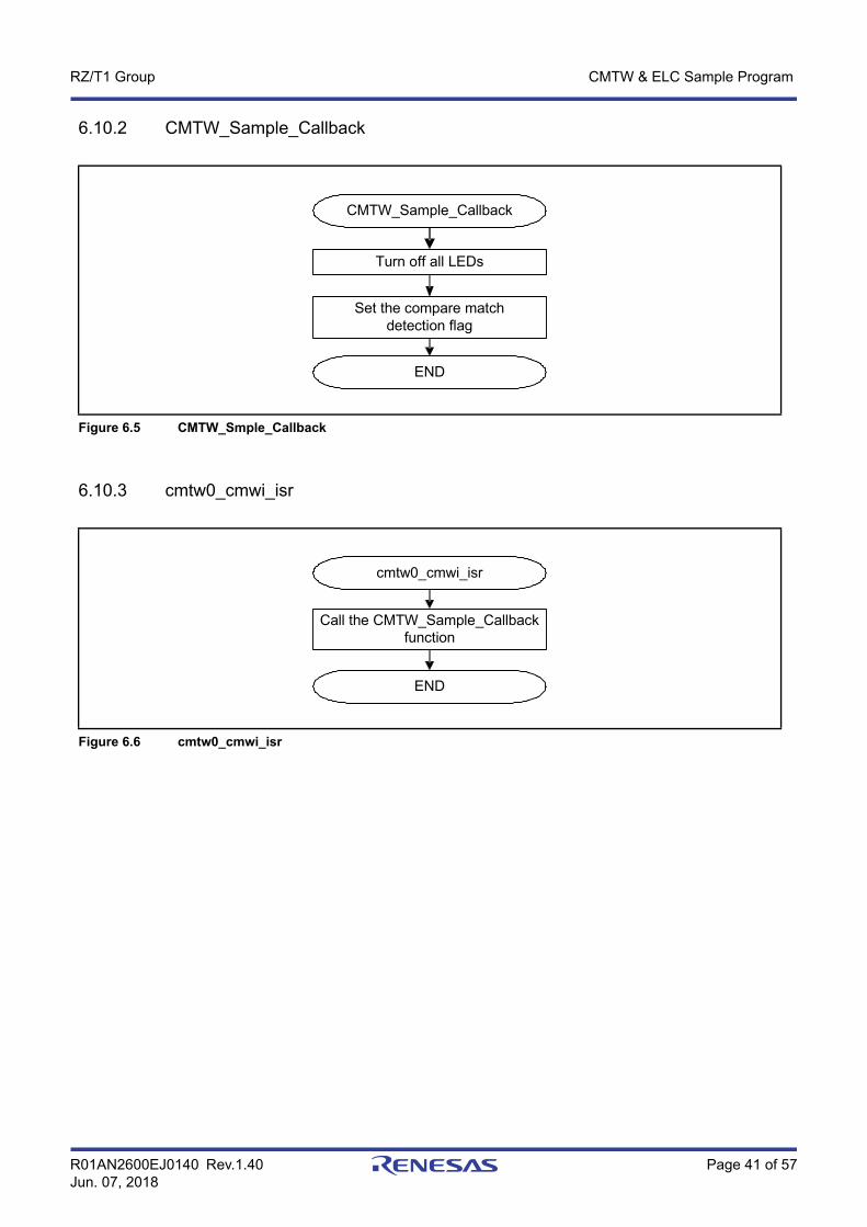
6.10.2 CMTW_Sample_Callback
6.10.3 cmtw0_cmwi_isr
Figure 6.5 CMTW_Smple_Callback
Figure 6.6 cmtw0_cmwi_isr
CMTW_Sample_Callback
Set the compare match detection flag
END
Turn off all LEDs
cmtw0_cmwi_isr
Call the CMTW_Sample_Callback function
END
R01AN2600EJ0140 Rev.1.40 Page 42 of 57Jun. 07, 2018
RZ/T1 Group CMTW & ELC Sample Program
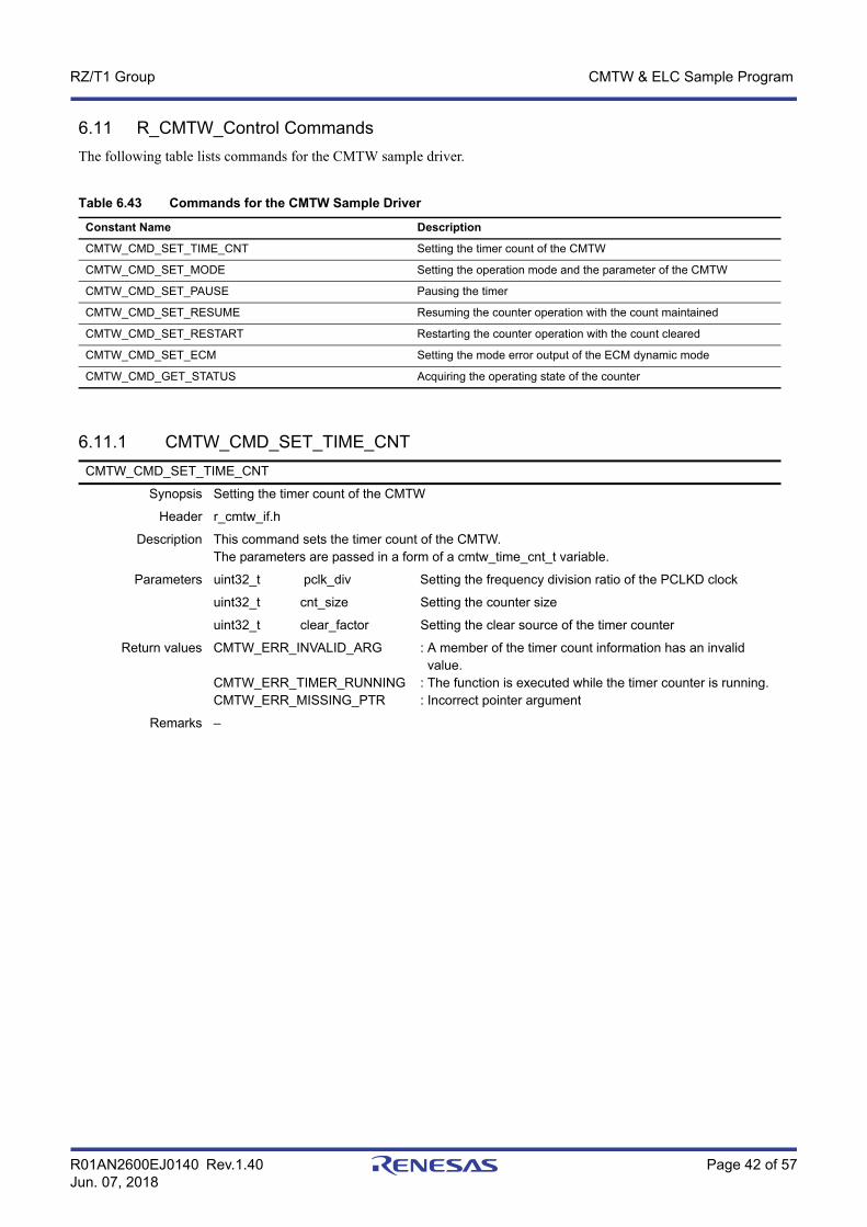
6.11 R_CMTW_Control CommandsThe following table lists commands for the CMTW sample driver.
6.11.1 CMTW_CMD_SET_TIME_CNT
Table 6.43 Commands for the CMTW Sample Driver
Constant Name Description
CMTW_CMD_SET_TIME_CNT Setting the timer count of the CMTW
CMTW_CMD_SET_MODE Setting the operation mode and the parameter of the CMTW
CMTW_CMD_SET_PAUSE Pausing the timer
CMTW_CMD_SET_RESUME Resuming the counter operation with the count maintained
CMTW_CMD_SET_RESTART Restarting the counter operation with the count cleared
CMTW_CMD_SET_ECM Setting the mode error output of the ECM dynamic mode
CMTW_CMD_GET_STATUS Acquiring the operating state of the counter
CMTW_CMD_SET_TIME_CNT
Synopsis Setting the timer count of the CMTW
Header r_cmtw_if.h
Description This command sets the timer count of the CMTW.The parameters are passed in a form of a cmtw_time_cnt_t variable.
Parameters uint32_t pclk_div Setting the frequency division ratio of the PCLKD clock
uint32_t cnt_size Setting the counter size
uint32_t clear_factor Setting the clear source of the timer counter
Return values CMTW_ERR_INVALID_ARG
CMTW_ERR_TIMER_RUNNINGCMTW_ERR_MISSING_PTR
: A member of the timer count information has an invalid value.: The function is executed while the timer counter is running.: Incorrect pointer argument
Remarks –
R01AN2600EJ0140 Rev.1.40 Page 43 of 57Jun. 07, 2018
RZ/T1 Group CMTW & ELC Sample Program
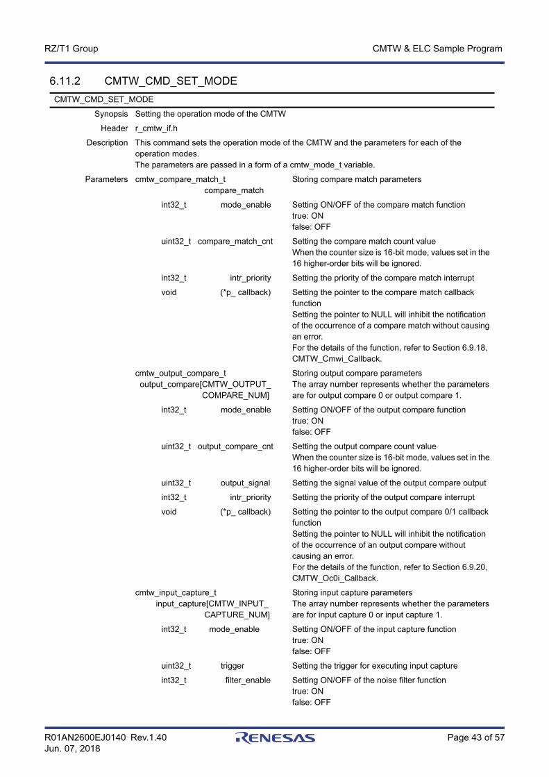
6.11.2 CMTW_CMD_SET_MODECMTW_CMD_SET_MODE
Synopsis Setting the operation mode of the CMTW
Header r_cmtw_if.h
Description This command sets the operation mode of the CMTW and the parameters for each of the operation modes. The parameters are passed in a form of a cmtw_mode_t variable.
Parameters cmtw_compare_match_t compare_match
Storing compare match parameters
int32_t mode_enable Setting ON/OFF of the compare match functiontrue: ONfalse: OFF
uint32_t compare_match_cnt Setting the compare match count valueWhen the counter size is 16-bit mode, values set in the 16 higher-order bits will be ignored.
int32_t intr_priority Setting the priority of the compare match interrupt
void (*p_ callback) Setting the pointer to the compare match callback functionSetting the pointer to NULL will inhibit the notification of the occurrence of a compare match without causing an error.For the details of the function, refer to Section 6.9.18, CMTW_Cmwi_Callback.
cmtw_output_compare_t output_compare[CMTW_OUTPUT_ COMPARE_NUM]
Storing output compare parameters The array number represents whether the parameters are for output compare 0 or output compare 1.
int32_t mode_enable Setting ON/OFF of the output compare functiontrue: ONfalse: OFF
uint32_t output_compare_cnt Setting the output compare count valueWhen the counter size is 16-bit mode, values set in the 16 higher-order bits will be ignored.
uint32_t output_signal Setting the signal value of the output compare output
int32_t intr_priority Setting the priority of the output compare interrupt
void (*p_ callback) Setting the pointer to the output compare 0/1 callback functionSetting the pointer to NULL will inhibit the notification of the occurrence of an output compare without causing an error.For the details of the function, refer to Section 6.9.20, CMTW_Oc0i_Callback.
cmtw_input_capture_t input_capture[CMTW_INPUT_ CAPTURE_NUM]
Storing input capture parametersThe array number represents whether the parameters are for input capture 0 or input capture 1.
int32_t mode_enable Setting ON/OFF of the input capture functiontrue: ONfalse: OFF
uint32_t trigger Setting the trigger for executing input capture
int32_t filter_enable Setting ON/OFF of the noise filter functiontrue: ONfalse: OFF

R01AN2600EJ0140 Rev.1.40 Page 44 of 57Jun. 07, 2018
RZ/T1 Group CMTW & ELC Sample Program
6.11.3 CMTW_CMD_SET_PAUSE
6.11.4 CMTW_CMD_SET_RESUME
int32_t intr_priority Setting the priority of the input capture interrupt
void (*p_ callback) Setting the pointer to the input capture 0/1 callback functionSetting the pointer to NULL will inhibit the notification of the occurrence of an input capture without causing an error.For the details of the function, refer to Section 6.9.19, CMTW_Ic0i_Callback.
uint32_t noise_filter_clk Setting the frequency division ratio of the PCLKD clock used for the noise filterThis parameter is valid when multiple noise filters are available in input capture 0/1.
Return values CMTW_ERR_INVALID_ARG
CMTW_ERR_TIMER_RUNNING
CMTW_ERR_MISSING_PTR
: A member of the timer count information has an invalid value.: The function is executed while the timer counter is running.: Incorrect pointer argument
Remarks –
CMTW_CMD_SET_TIME_PAUSE
Synopsis Pausing the timer
Header r_cmtw_if.h
Description This command pauses the timer count of the CMTW. When called with the timer counter stopping, the command ends without executing any processing.
Parameters None
Return values CMTW_ERR_TIMER_STOP : Executed without starting timer count once after initialization
Remarks –
CMTW_CMD_SET_TIME_RESUME
Synopsis Resuming counting with the timer count maintained
Header r_cmtw_if.h
Description This command resumes counting with the timer count value at the time of being paused maintained. When called with the timer counter running, the command ends without executing any processing.
Parameters None
Return values CMTW_ERR_TIMER_STOPCMTW_ERR_TIMER_RUNNING
: Executed without starting timer count once after initialization: The function is executed while the timer counter is running.
Remarks –
R01AN2600EJ0140 Rev.1.40 Page 45 of 57Jun. 07, 2018
RZ/T1 Group CMTW & ELC Sample Program
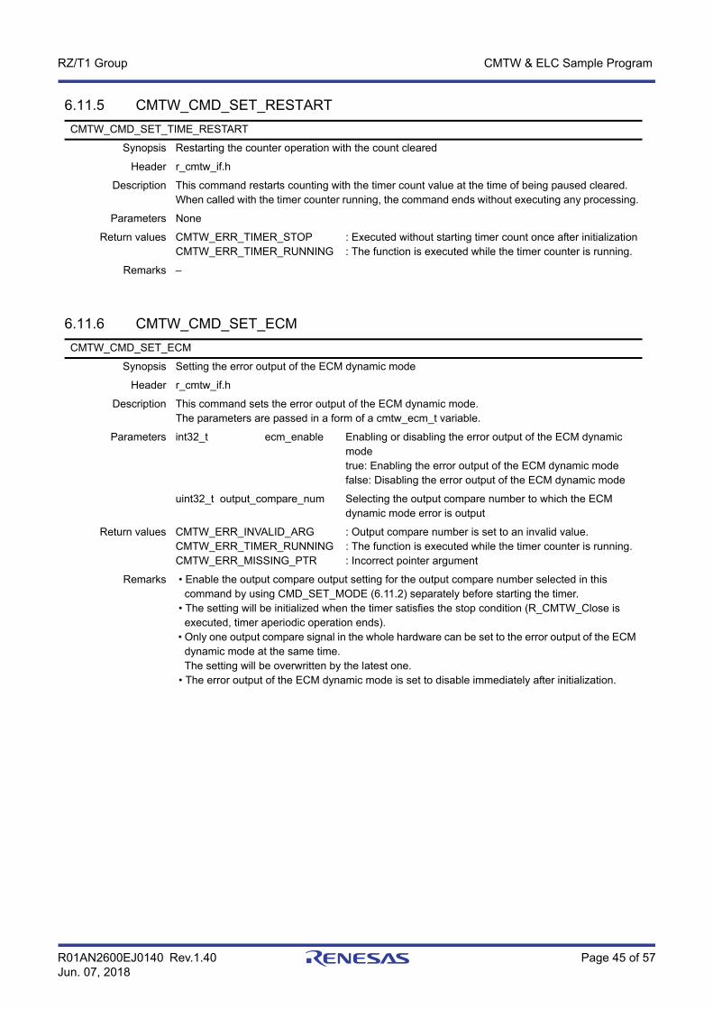
6.11.5 CMTW_CMD_SET_RESTART
6.11.6 CMTW_CMD_SET_ECM
CMTW_CMD_SET_TIME_RESTART
Synopsis Restarting the counter operation with the count cleared
Header r_cmtw_if.h
Description This command restarts counting with the timer count value at the time of being paused cleared. When called with the timer counter running, the command ends without executing any processing.
Parameters None
Return values CMTW_ERR_TIMER_STOPCMTW_ERR_TIMER_RUNNING
: Executed without starting timer count once after initialization: The function is executed while the timer counter is running.
Remarks –
CMTW_CMD_SET_ECM
Synopsis Setting the error output of the ECM dynamic mode
Header r_cmtw_if.h
Description This command sets the error output of the ECM dynamic mode. The parameters are passed in a form of a cmtw_ecm_t variable.
Parameters int32_t ecm_enable Enabling or disabling the error output of the ECM dynamic modetrue: Enabling the error output of the ECM dynamic modefalse: Disabling the error output of the ECM dynamic mode
uint32_t output_compare_num Selecting the output compare number to which the ECM dynamic mode error is output
Return values CMTW_ERR_INVALID_ARGCMTW_ERR_TIMER_RUNNINGCMTW_ERR_MISSING_PTR
: Output compare number is set to an invalid value.: The function is executed while the timer counter is running.: Incorrect pointer argument
Remarks • Enable the output compare output setting for the output compare number selected in this command by using CMD_SET_MODE (6.11.2) separately before starting the timer. • The setting will be initialized when the timer satisfies the stop condition (R_CMTW_Close is executed, timer aperiodic operation ends). • Only one output compare signal in the whole hardware can be set to the error output of the ECM dynamic mode at the same time. The setting will be overwritten by the latest one. • The error output of the ECM dynamic mode is set to disable immediately after initialization.

R01AN2600EJ0140 Rev.1.40 Page 46 of 57Jun. 07, 2018
RZ/T1 Group CMTW & ELC Sample Program
6.11.7 CMTW_CMD_GET_STATUSCMTW_CMD_GET_STATUS
Synopsis Acquiring the operating state of the timer
Header r_cmtw_if.h
Description This command acquires the operating state of the timer.The operating state is passed as a cmtw_status_t pointer variable. The parameter name below is an example.
Parameters uint32_t *p_cmtw_status Storing the operating state of the timerEither of the following values is returned. CMTW_STATUS_STOP: Timer has been stoppedCMTW_STATUS_RUNNING: Timer is running
Return values CMTW_ERR_INVALID_ARG : The pointer to the timer operation state acquisition parameter has an invalid value.
Remarks –

R01AN2600EJ0140 Rev.1.40 Page 47 of 57Jun. 07, 2018
RZ/T1 Group CMTW & ELC Sample Program
6.12 R_ELC_Control CommandsThe following table lists commands for the ELC sample driver.
6.12.1 ELC_CMD_SET_EVENT_MTU
Table 6.44 Commands for the ELC Sample Driver
Constant Name Description
ELC_CMD_SET_EVENT_MTU Setting event link to an MTU module
ELC_CMD_SET_EVENT_CMT Setting event link to a CMT module
ELC_CMD_SET_EVENT_DSMIF Setting event link to a ΔΣ unit module
ELC_CMD_SET_EVENT_S12AD Setting event link to a 12-bit A/D converter
ELC_CMD_SET_EVENT_INTR Setting event link to an interrupt request signal to the ELC
ELC_CMD_SET_EVENT_OUT_PORT_GROUP Setting event link to an output port group
ELC_CMD_SET_EVENT_IN_PORT_GROUP Setting event link to an input port group
ELC_CMD_SET_EVENT_SINGLE_PORT Setting a single port and setting event link to the port
ELC_CMD_SET_EVENT_CMTW Setting event link parameters to the CMTW0
ELC_CMD_SET_EVENT_TPU Setting event link parameters to a TPU module
ELC_CMD_SET_EVENT_GPT Setting event link parameters to a GPT module
ELC_CMD_SET_PORT_GROUP Setting a port group
ELC_CMD_SET_SOFTWARE_EVENT Issuing a software event of the ELC
ELC_CMD_GET_PORT_GROUP_VALUE Acquiring the signal value of a port group
ELC_CMD_SET_EVENT_MTU
Synopsis Setting event link parameters to the MTU0, MTU3, or MTU4
Header r_elc_if.h
Description This command sets event link parameters of the ELC to the MTU0, MTU3, or MTU4The parameters are passed in a form of an elc_cmd_mtu_t variable.
Parameters uint32_t elc_mtu_ch Specifying the MTU unit number to be set.
int32_t event_link_enable Setting ON/OFF of the event link to the MTUtrue: ONfalse: OFF
uint32_t resource Setting the event signal of the event link source
uint32_t action Setting the action when an event link occurs to the MTU
Return values ELC_ERR_INVALID_ARGELC_ERR_MISSING_PTR
: A member of the event link information has an invalid value: Incorrect pointer argument
Remarks –

R01AN2600EJ0140 Rev.1.40 Page 48 of 57Jun. 07, 2018
RZ/T1 Group CMTW & ELC Sample Program
6.12.2 ELC_CMD_SET_EVENT_CMT
6.12.3 ELC_CMD_SET_EVENT_DSMIF
ELC_CMD_SET_EVENT_CMT
Synopsis Setting event link parameters to the CMT1
Header r_elc_if.h
Description This command sets event link parameters of the ELC to the CMT1. The parameters are passed in a form of an elc_cmd_cmt_t variable.
Parameters int32_t event_link_enable Setting ON/OFF of the event link to the CMT1true: ONfalse: OFF
uint32_t resource Setting the event signal of the event link source
uint32_t action Setting the action when an event link occurs to the CMT1
Return values ELC_ERR_INVALID_ARGELC_ERR_MISSING_PTR
: A member of the event link information has an invalid value.: Incorrect pointer argument
Remarks –
ELC_CMD_SET_EVENT_DSMIF
Synopsis Setting event link parameters to the ΔΣ unit 0/1 trigger 0/1
Header r_elc_if.h
Description This command sets event link parameters of the ELC to the ΔΣ unit 0/1 trigger 0/1The parameters are passed in a form of an elc_cmd_dsmif_t variable.
Parameters uint32_t elc_dsmif_ch Specifying the number of the ΔΣ unit 0/1 trigger 0/1 to be set
int32_t event_link_enable Setting ON/OFF of the event link to the ΔΣ unit true: ONfalse: OFF
uint32_t resource Setting the event signal of the event link source
Return values ELC_ERR_INVALID_ARGELC_ERR_MISSING_PTR
: A member of the event link information has an invalid value.: Incorrect pointer argument
Remarks –

R01AN2600EJ0140 Rev.1.40 Page 49 of 57Jun. 07, 2018
RZ/T1 Group CMTW & ELC Sample Program
6.12.4 ELC_CMD_SET_EVENT_S12AD
6.12.5 ELC_CMD_SET_EVENT_INTR
ELC_CMD_SET_EVENT_S12AD
Synopsis Setting event link parameters to the 12-bit A/D converter 0 or 1
Header r_elc_if.h
Description This command sets event link parameters of the ELC to the 12-bit A/D converter 0 or 1. The parameters are passed in a form of an elc_cmd_s12ad_t variable.
Parameters uint32_t elc_s12ad_ch Setting the number of the 12-bit A/D converter to be set
int32_t event_link_enable Setting ON/OFF of the event link to the 12-bit A/D convertertrue: ONfalse: OFF
uint32_t resource Setting the event signal of the event link source
Return values ELC_ERR_INVALID_ARGELC_ERR_MISSING_PTR
: A member of the event link information has an invalid value.: Incorrect pointer argument
Remarks –
ELC_CMD_SET_EVENT_INTR
Synopsis Setting event link parameters to the interrupt request signal 1 or 2 of the ELC
Header r_elc_if.h
Description This command sets event link parameters of the ELC to the interrupt request signal 1 or 2 of the ELC. The parameters are passed in a form of an elc_cmd_intr_t variable.
Parameters uint32_t elc_intr_num Specifying the number of the interrupt request signal
int32_t event_link_enable Setting ON/OFF of the event link to the interrupt request signal 1 or 2true: ONfalse: OFF
uint32_t resource Setting the event signal of the event link source
int32_t intr_priority Setting the priority of the interrupt
void (*p_ callback) Setting the pointer to the event link callback functionSetting the pointer to NULL will inhibit the notification of the occurrence of an interrupt without causing an error.For the details of the function, refer to Section 6.9.21, ELC_Elci_Callback.
Return values ELC_ERR_INVALID_ARGELC_ERR_MISSING_PTR
: A member of the event link information has an invalid value.: Incorrect pointer argument
Remarks –

R01AN2600EJ0140 Rev.1.40 Page 50 of 57Jun. 07, 2018
RZ/T1 Group CMTW & ELC Sample Program
6.12.6 ELC_CMD_SET_EVENT_OUT_PORT_GROUP
6.12.7 ELC_CMD_SET_EVENT_IN_PORT_GROUP
ELC_CMD_SET_EVENT_OUT_PORT_GROUP
Synopsis Setting event link parameters to the output port group 1 or 2
Header r_elc_if.h
Description This command sets event link parameters of the ELC to the output port group 1 or 2. The parameters are passed in a form of an elc_cmd_out_port_group_t variable.
Parameters uint32_t elc_out_port_group_num Specifying the number of the output port group
int32_t event_link_enable Setting ON/OFF of the event link to the output port group 1 or 2true: ONfalse: OFF
uint32_t resource Setting the event signal of the event link source
uint32_t action Setting the action when an event link occurs to the output port group 1 or 2
uint8_t init_value Setting the initial output value of the output port groupWhen action is set to ELC_OUT_GROUP_OUTPUT_0 and ELC_OUT_GROUP_OUTPUT_1, the setting value will be ignored.
Return values ELC_ERR_INVALID_ARG
ELC_ERR_MISSING_PTR
: A member of the event link information has an invalid value.: Incorrect pointer argument
Remarks • After resetting the rotate state to the initial state while rotate output has been set, use this command to set the parameters of the initial state again.
ELC_CMD_SET_EVENT_IN_PORT_GROUP
Synopsis Setting event link parameters to the input port group 1 or 2
Header r_elc_if.h
Description This command sets event link parameters of the ELC to the input port group 1 or 2. The parameters are passed in a form of an elc_cmd_in_port_group_t variable.
Parameters uint32_t elc_in_port_group_num Specifying the number of the input port group
int32_t event_link_enable Setting ON/OFF of the event link to the input port group 1 or 2true: ONfalse: OFF
uint32_t resource Setting the event signal of the event link source
int32_t overwrite_enable Setting whether or not to enable overwriting signal values on the buffer at the occurrence of an eventtrue: Enabling overwritefalse: Disabling overwrite
Return values ELC_ERR_INVALID_ARG
ELC_ERR_MISSING_PTR
: A member of the event link information has an invalid value.: Incorrect pointer argument
Remarks When overwriting signal values on the buffer is disabled at the occurrence of an event, the following event will be ignored until the buffer value is read out. Use ELC_CMD_GET_PORT_GROUP_VALUE (6.12.14) for reading out buffer values.
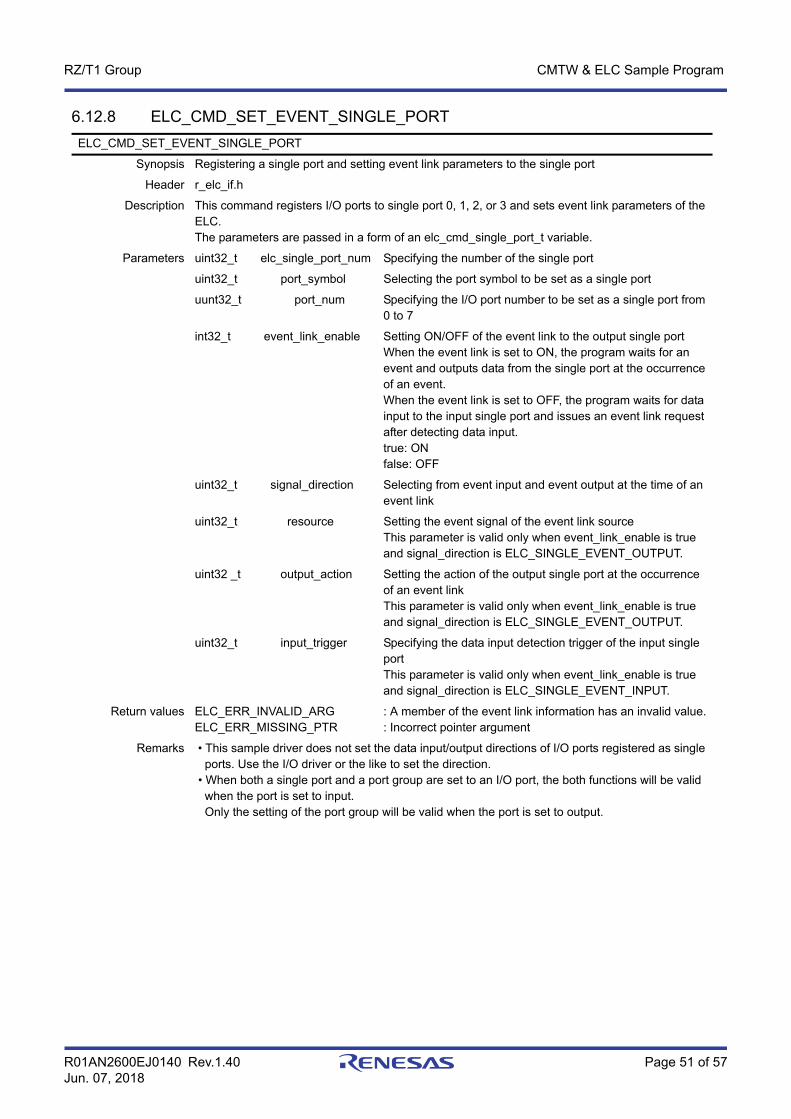
R01AN2600EJ0140 Rev.1.40 Page 51 of 57Jun. 07, 2018
RZ/T1 Group CMTW & ELC Sample Program
6.12.8 ELC_CMD_SET_EVENT_SINGLE_PORTELC_CMD_SET_EVENT_SINGLE_PORT
Synopsis Registering a single port and setting event link parameters to the single port
Header r_elc_if.h
Description This command registers I/O ports to single port 0, 1, 2, or 3 and sets event link parameters of the ELC. The parameters are passed in a form of an elc_cmd_single_port_t variable.
Parameters uint32_t elc_single_port_num Specifying the number of the single port
uint32_t port_symbol Selecting the port symbol to be set as a single port
uunt32_t port_num Specifying the I/O port number to be set as a single port from 0 to 7
int32_t event_link_enable Setting ON/OFF of the event link to the output single portWhen the event link is set to ON, the program waits for an event and outputs data from the single port at the occurrence of an event. When the event link is set to OFF, the program waits for data input to the input single port and issues an event link request after detecting data input. true: ONfalse: OFF
uint32_t signal_direction Selecting from event input and event output at the time of an event link
uint32_t resource Setting the event signal of the event link sourceThis parameter is valid only when event_link_enable is true and signal_direction is ELC_SINGLE_EVENT_OUTPUT.
uint32 _t output_action Setting the action of the output single port at the occurrence of an event linkThis parameter is valid only when event_link_enable is true and signal_direction is ELC_SINGLE_EVENT_OUTPUT.
uint32_t input_trigger Specifying the data input detection trigger of the input single portThis parameter is valid only when event_link_enable is true and signal_direction is ELC_SINGLE_EVENT_INPUT.
Return values ELC_ERR_INVALID_ARGELC_ERR_MISSING_PTR
: A member of the event link information has an invalid value.: Incorrect pointer argument
Remarks • This sample driver does not set the data input/output directions of I/O ports registered as single ports. Use the I/O driver or the like to set the direction. • When both a single port and a port group are set to an I/O port, the both functions will be valid when the port is set to input. Only the setting of the port group will be valid when the port is set to output.
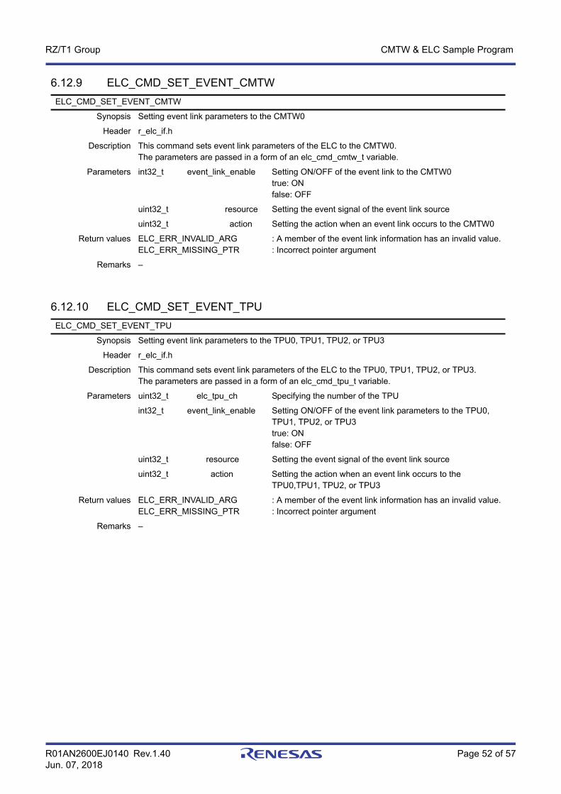
R01AN2600EJ0140 Rev.1.40 Page 52 of 57Jun. 07, 2018
RZ/T1 Group CMTW & ELC Sample Program
6.12.9 ELC_CMD_SET_EVENT_CMTW
6.12.10 ELC_CMD_SET_EVENT_TPU
ELC_CMD_SET_EVENT_CMTW
Synopsis Setting event link parameters to the CMTW0
Header r_elc_if.h
Description This command sets event link parameters of the ELC to the CMTW0.The parameters are passed in a form of an elc_cmd_cmtw_t variable.
Parameters int32_t event_link_enable Setting ON/OFF of the event link to the CMTW0true: ONfalse: OFF
uint32_t resource Setting the event signal of the event link source
uint32_t action Setting the action when an event link occurs to the CMTW0
Return values ELC_ERR_INVALID_ARGELC_ERR_MISSING_PTR
: A member of the event link information has an invalid value.: Incorrect pointer argument
Remarks –
ELC_CMD_SET_EVENT_TPU
Synopsis Setting event link parameters to the TPU0, TPU1, TPU2, or TPU3
Header r_elc_if.h
Description This command sets event link parameters of the ELC to the TPU0, TPU1, TPU2, or TPU3.The parameters are passed in a form of an elc_cmd_tpu_t variable.
Parameters uint32_t elc_tpu_ch Specifying the number of the TPU
int32_t event_link_enable Setting ON/OFF of the event link parameters to the TPU0, TPU1, TPU2, or TPU3true: ONfalse: OFF
uint32_t resource Setting the event signal of the event link source
uint32_t action Setting the action when an event link occurs to the TPU0,TPU1, TPU2, or TPU3
Return values ELC_ERR_INVALID_ARGELC_ERR_MISSING_PTR
: A member of the event link information has an invalid value.: Incorrect pointer argument
Remarks –
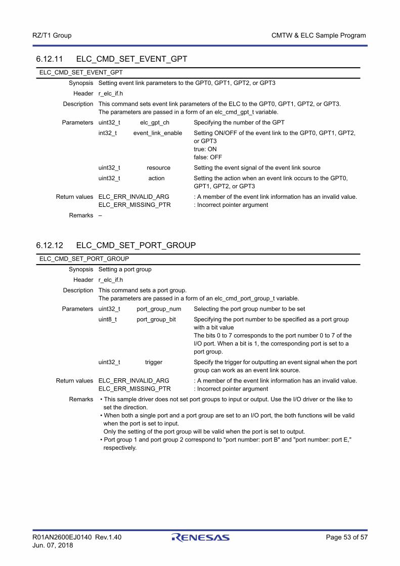
R01AN2600EJ0140 Rev.1.40 Page 53 of 57Jun. 07, 2018
RZ/T1 Group CMTW & ELC Sample Program
6.12.11 ELC_CMD_SET_EVENT_GPT
6.12.12 ELC_CMD_SET_PORT_GROUP
ELC_CMD_SET_EVENT_GPT
Synopsis Setting event link parameters to the GPT0, GPT1, GPT2, or GPT3
Header r_elc_if.h
Description This command sets event link parameters of the ELC to the GPT0, GPT1, GPT2, or GPT3.The parameters are passed in a form of an elc_cmd_gpt_t variable.
Parameters uint32_t elc_gpt_ch Specifying the number of the GPT
int32_t event_link_enable Setting ON/OFF of the event link to the GPT0, GPT1, GPT2, or GPT3true: ONfalse: OFF
uint32_t resource Setting the event signal of the event link source
uint32_t action Setting the action when an event link occurs to the GPT0, GPT1, GPT2, or GPT3
Return values ELC_ERR_INVALID_ARGELC_ERR_MISSING_PTR
: A member of the event link information has an invalid value.: Incorrect pointer argument
Remarks –
ELC_CMD_SET_PORT_GROUP
Synopsis Setting a port group
Header r_elc_if.h
Description This command sets a port group.The parameters are passed in a form of an elc_cmd_port_group_t variable.
Parameters uint32_t port_group_num Selecting the port group number to be set
uint8_t port_group_bit Specifying the port number to be specified as a port group with a bit valueThe bits 0 to 7 corresponds to the port number 0 to 7 of the I/O port. When a bit is 1, the corresponding port is set to a port group.
uint32_t trigger Specify the trigger for outputting an event signal when the port group can work as an event link source.
Return values ELC_ERR_INVALID_ARGELC_ERR_MISSING_PTR
: A member of the event link information has an invalid value.: Incorrect pointer argument
Remarks • This sample driver does not set port groups to input or output. Use the I/O driver or the like to set the direction. • When both a single port and a port group are set to an I/O port, the both functions will be valid when the port is set to input. Only the setting of the port group will be valid when the port is set to output. • Port group 1 and port group 2 correspond to "port number: port B" and "port number: port E," respectively.

R01AN2600EJ0140 Rev.1.40 Page 54 of 57Jun. 07, 2018
RZ/T1 Group CMTW & ELC Sample Program
6.12.13 ELC_CMD_SET_SOFTWARE_EVENT
6.12.14 ELC_CMD_GET_PORT_GROUP_VALUE
ELC_CMD_SET_SOFTWARE_EVENT
Synopsis Issuing a software event of the ELC
Header r_elc_if.h
Description This command issues a software event of the ELC.
Parameters None
Return values None
Remarks –
ELC_CMD_GET_PORT_GROUP_VALUE
Synopsis Acquiring the signal value of a port group
Header r_elc_if.h
Description This command acquires the signal value of a port group. The parameters are passed in a form of an elc_get_port_value_t variable.
Parameters uint32_t port_group_num Specifying the port group number from which the value is acquired
uint8_t *p_port_value Storing the signal value of the input port group
Return values ELC_ERR_INVALID_ARGELC_ERR_MISSING_PTR
: Incorrect port group number is specified: Incorrect pointer argument
Remarks –
R01AN2600EJ0140 Rev.1.40 Page 55 of 57Jun. 07, 2018
RZ/T1 Group CMTW & ELC Sample Program
7. Sample CodeThe sample code can be downloaded from the Renesas Electronics website.
R01AN2600EJ0140 Rev.1.40 Page 56 of 57Jun. 07, 2018
RZ/T1 Group CMTW & ELC Sample Program
8. Related Documents• User’s manual: Hardware
RZ/T1 Group User’s Manual: Hardware (Download the latest version from the Renesas Electronics website.)
RZ/T1 Evaluation Board RTK7910022C00000BR User’s Manual (Download the latest version from the Renesas Electronics website.)
• Technical Updates/Technical News (Download the latest information from the Renesas Electronics website.)
• User’s Manual: Development environment Download the IAR Embedded Workbench® for Arm from the IAR website.(Download the latest version from the IAR website.)

R01AN2600EJ0140 Rev.1.40 Page 57 of 57Jun. 07, 2018
RZ/T1 Group CMTW & ELC Sample Program
Website and SupportRenesas Electronics website
http://www.renesas.com/
Inquiries
http://www.renesas.com/inquiry
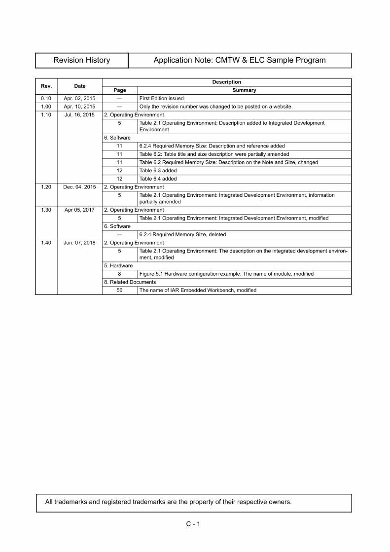
Application Note: CMTW & ELC Sample Program
C - 1
Rev. DateDescription
Page Summary0.10 Apr. 02, 2015 — First Edition issued1.00 Apr. 10, 2015 — Only the revision number was changed to be posted on a website.1.10 Jul. 16, 2015 2. Operating Environment
5 Table 2.1 Operating Environment: Description added to Integrated Development Environment
6. Software11 6.2.4 Required Memory Size: Description and reference added11 Table 6.2: Table title and size description were partially amended11 Table 6.2 Required Memory Size: Description on the Note and Size, changed12 Table 6.3 added12 Table 6.4 added
1.20 Dec. 04, 2015 2. Operating Environment5 Table 2.1 Operating Environment: Integrated Development Environment, information
partially amended1.30 Apr 05, 2017 2. Operating Environment
5 Table 2.1 Operating Environment: Integrated Development Environment, modified6. Software
— 6.2.4 Required Memory Size, deleted1.40 Jun. 07, 2018 2. Operating Environment
5 Table 2.1 Operating Environment: The description on the integrated development environ-ment, modified
5. Hardware8 Figure 5.1 Hardware configuration example: The name of module, modified
8. Related Documents56 The name of IAR Embedded Workbench, modified
All trademarks and registered trademarks are the property of their respective owners.
Revision History

General Precautions in the Handling of Microprocessing Unit and Microcontroller Unit Products
The following usage notes are applicable to all Microprocessing unit and Microcontroller unit products from Renesas.
For detailed usage notes on the products covered by this document, refer to the relevant sections of the document as well
as any technical updates that have been issued for the products.
1. Handling of Unused PinsHandle unused pins in accordance with the directions given under Handling of Unused Pins in the manual.⎯ The input pins of CMOS products are generally in the high-impedance state. In operation with an
unused pin in the open-circuit state, extra electromagnetic noise is induced in the vicinity of LSI, an associated shoot-through current flows internally, and malfunctions occur due to the false recognition of the pin state as an input signal become possible. Unused pins should be handled as described under Handling of Unused Pins in the manual.
2. Processing at Power-onThe state of the product is undefined at the moment when power is supplied.⎯ The states of internal circuits in the LSI are indeterminate and the states of register settings and
pins are undefined at the moment when power is supplied.In a finished product where the reset signal is applied to the external reset pin, the states of pins are not guaranteed from the moment when power is supplied until the reset process is completed.In a similar way, the states of pins in a product that is reset by an on-chip power-on reset functionare not guaranteed from the moment when power is supplied until the power reaches the level at which resetting has been specified.
3. Prohibition of Access to Reserved AddressesAccess to reserved addresses is prohibited.⎯ The reserved addresses are provided for the possible future expansion of functions. Do not access
these addresses; the correct operation of LSI is not guaranteed if they are accessed.4. Clock Signals
After applying a reset, only release the reset line after the operating clock signal has become stable. When switching the clock signal during program execution, wait until the target clock signal has stabilized.⎯ When the clock signal is generated with an external resonator (or from an external oscillator)
during a reset, ensure that the reset line is only released after full stabilization of the clock signal. Moreover, when switching to a clock signal produced with an external resonator (or by an external oscillator) while program execution is in progress, wait until the target clock signal is stable.
5. Differences between ProductsBefore changing from one product to another, i.e. to a product with a different part number, confirm that the change will not lead to problems.⎯ The characteristics of Microprocessing unit or Microcontroller unit products in the same group but
having a different part number may differ in terms of the internal memory capacity, layout pattern, and other factors, which can affect the ranges of electrical characteristics, such as characteristic values, operating margins, immunity to noise, and amount of radiated noise. When changing to a product with a different part number, implement a system-evaluation test for the given product.
General Precautions in the Handling of
Microprocessing Unit and Microcontroller Unit Products
http://www.renesas.comRefer to "http://www.renesas.com/" for the latest and detailed information.
Renesas Electronics America Inc.1001 Murphy Ranch Road, Milpitas, CA 95035, U.S.A.Tel: +1-408-432-8888, Fax: +1-408-434-5351Renesas Electronics Canada Limited9251 Yonge Street, Suite 8309 Richmond Hill, Ontario Canada L4C 9T3Tel: +1-905-237-2004Renesas Electronics Europe LimitedDukes Meadow, Millboard Road, Bourne End, Buckinghamshire, SL8 5FH, U.KTel: +44-1628-651-700, Fax: +44-1628-651-804Renesas Electronics Europe GmbHArcadiastrasse 10, 40472 Düsseldorf, Germany Tel: +49-211-6503-0, Fax: +49-211-6503-1327Renesas Electronics (China) Co., Ltd.Room 1709 Quantum Plaza, No.27 ZhichunLu, Haidian District, Beijing, 100191 P. R. ChinaTel: +86-10-8235-1155, Fax: +86-10-8235-7679Renesas Electronics (Shanghai) Co., Ltd.Unit 301, Tower A, Central Towers, 555 Langao Road, Putuo District, Shanghai, 200333 P. R. China Tel: +86-21-2226-0888, Fax: +86-21-2226-0999Renesas Electronics Hong Kong LimitedUnit 1601-1611, 16/F., Tower 2, Grand Century Place, 193 Prince Edward Road West, Mongkok, Kowloon, Hong KongTel: +852-2265-6688, Fax: +852 2886-9022Renesas Electronics Taiwan Co., Ltd.13F, No. 363, Fu Shing North Road, Taipei 10543, TaiwanTel: +886-2-8175-9600, Fax: +886 2-8175-9670Renesas Electronics Singapore Pte. Ltd.80 Bendemeer Road, Unit #06-02 Hyflux Innovation Centre, Singapore 339949Tel: +65-6213-0200, Fax: +65-6213-0300Renesas Electronics Malaysia Sdn.Bhd.Unit 1207, Block B, Menara Amcorp, Amcorp Trade Centre, No. 18, Jln Persiaran Barat, 46050 Petaling Jaya, Selangor Darul Ehsan, MalaysiaTel: +60-3-7955-9390, Fax: +60-3-7955-9510Renesas Electronics India Pvt. Ltd.No.777C, 100 Feet Road, HAL 2nd Stage, Indiranagar, Bangalore 560 038, IndiaTel: +91-80-67208700, Fax: +91-80-67208777Renesas Electronics Korea Co., Ltd.17F, KAMCO Yangjae Tower, 262, Gangnam-daero, Gangnam-gu, Seoul, 06265 KoreaTel: +82-2-558-3737, Fax: +82-2-558-5338
SALES OFFICES
© 2018 Renesas Electronics Corporation. All rights reserved.Colophon 7.0
(Rev.4.0-1 November 2017)
Notice
1. Descriptions of circuits, software and other related information in this document are provided only to illustrate the operation of semiconductor products and application examples. You are fully responsible for
the incorporation or any other use of the circuits, software, and information in the design of your product or system. Renesas Electronics disclaims any and all liability for any losses and damages incurred by
you or third parties arising from the use of these circuits, software, or information.
2. Renesas Electronics hereby expressly disclaims any warranties against and liability for infringement or any other claims involving patents, copyrights, or other intellectual property rights of third parties, by or
arising from the use of Renesas Electronics products or technical information described in this document, including but not limited to, the product data, drawings, charts, programs, algorithms, and application
examples.
3. No license, express, implied or otherwise, is granted hereby under any patents, copyrights or other intellectual property rights of Renesas Electronics or others.
4. You shall not alter, modify, copy, or reverse engineer any Renesas Electronics product, whether in whole or in part. Renesas Electronics disclaims any and all liability for any losses or damages incurred by
you or third parties arising from such alteration, modification, copying or reverse engineering.
5. Renesas Electronics products are classified according to the following two quality grades: “Standard” and “High Quality”. The intended applications for each Renesas Electronics product depends on the
product’s quality grade, as indicated below.
"Standard": Computers; office equipment; communications equipment; test and measurement equipment; audio and visual equipment; home electronic appliances; machine tools; personal electronic
equipment; industrial robots; etc.
"High Quality": Transportation equipment (automobiles, trains, ships, etc.); traffic control (traffic lights); large-scale communication equipment; key financial terminal systems; safety control equipment; etc.
Unless expressly designated as a high reliability product or a product for harsh environments in a Renesas Electronics data sheet or other Renesas Electronics document, Renesas Electronics products are
not intended or authorized for use in products or systems that may pose a direct threat to human life or bodily injury (artificial life support devices or systems; surgical implantations; etc.), or may cause
serious property damage (space system; undersea repeaters; nuclear power control systems; aircraft control systems; key plant systems; military equipment; etc.). Renesas Electronics disclaims any and all
liability for any damages or losses incurred by you or any third parties arising from the use of any Renesas Electronics product that is inconsistent with any Renesas Electronics data sheet, user’s manual or
other Renesas Electronics document.
6. When using Renesas Electronics products, refer to the latest product information (data sheets, user’s manuals, application notes, “General Notes for Handling and Using Semiconductor Devices” in the
reliability handbook, etc.), and ensure that usage conditions are within the ranges specified by Renesas Electronics with respect to maximum ratings, operating power supply voltage range, heat dissipation
characteristics, installation, etc. Renesas Electronics disclaims any and all liability for any malfunctions, failure or accident arising out of the use of Renesas Electronics products outside of such specified
ranges.
7. Although Renesas Electronics endeavors to improve the quality and reliability of Renesas Electronics products, semiconductor products have specific characteristics, such as the occurrence of failure at a
certain rate and malfunctions under certain use conditions. Unless designated as a high reliability product or a product for harsh environments in a Renesas Electronics data sheet or other Renesas
Electronics document, Renesas Electronics products are not subject to radiation resistance design. You are responsible for implementing safety measures to guard against the possibility of bodily injury, injury
or damage caused by fire, and/or danger to the public in the event of a failure or malfunction of Renesas Electronics products, such as safety design for hardware and software, including but not limited to
redundancy, fire control and malfunction prevention, appropriate treatment for aging degradation or any other appropriate measures. Because the evaluation of microcomputer software alone is very difficult
and impractical, you are responsible for evaluating the safety of the final products or systems manufactured by you.
8. Please contact a Renesas Electronics sales office for details as to environmental matters such as the environmental compatibility of each Renesas Electronics product. You are responsible for carefully and
sufficiently investigating applicable laws and regulations that regulate the inclusion or use of controlled substances, including without limitation, the EU RoHS Directive, and using Renesas Electronics
products in compliance with all these applicable laws and regulations. Renesas Electronics disclaims any and all liability for damages or losses occurring as a result of your noncompliance with applicable
laws and regulations.
9. Renesas Electronics products and technologies shall not be used for or incorporated into any products or systems whose manufacture, use, or sale is prohibited under any applicable domestic or foreign laws
or regulations. You shall comply with any applicable export control laws and regulations promulgated and administered by the governments of any countries asserting jurisdiction over the parties or
transactions.
10. It is the responsibility of the buyer or distributor of Renesas Electronics products, or any other party who distributes, disposes of, or otherwise sells or transfers the product to a third party, to notify such third
party in advance of the contents and conditions set forth in this document.
11. This document shall not be reprinted, reproduced or duplicated in any form, in whole or in part, without prior written consent of Renesas Electronics.
12. Please contact a Renesas Electronics sales office if you have any questions regarding the information contained in this document or Renesas Electronics products.
(Note 1) “Renesas Electronics” as used in this document means Renesas Electronics Corporation and also includes its directly or indirectly controlled subsidiaries.
(Note 2) “Renesas Electronics product(s)” means any product developed or manufactured by or for Renesas Electronics.
ご注意書き