Embed Size (px)
Citation preview
1
RX Frequency inverters
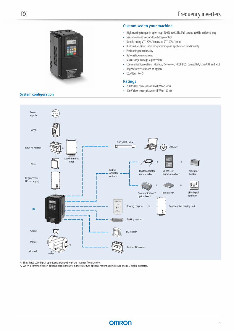
Customised to your machine
• High starting torque in open loop: 200% at 0.3 Hz, Full torque at 0 Hz in closed loop• Sensor-less and vector closed-loop control• Double rating VT 120%/1 min and CT 150%/1 min• Built-in EMC filter, logic programming and application functionality• Positioning functionality• Automatic energy saving• Micro-surge voltage suppression• Communication options: Modbus, DeviceNet, PROFIBUS, CompoNet, EtherCAT and ML2• Regenerative solutions as option• CE, cULus, RoHS
Ratings• 200 V class three-phase: 0.4 kW to 55 kW• 400 V class three-phase: 0.4 kW to 132 kW
System configuration
*1 The 5 lines LCD digital operator is provided with the inverter from factory.*2 When a communication option board is mounted, there are two options: mount a blind cover or a LED digital operator.
Choke
5 lines LCDdigital operator
Digital operatorremote cable
Output AC reactor
Braking chopper or
Braking resistor
Operatorholder
LED digital operator
Blind cover
+ +
or
RJ45 - USB cable
Software
Digital operator options
MCCB
Filter
Input AC reactor
Motor
Ground
Power supply
DC reactor
+
*1
RX
Low harmonicfilter
or
Regeneretive DC bus supply
Regenerative braking unit
Communicationoption board
*2
RX Frequency inverters
2
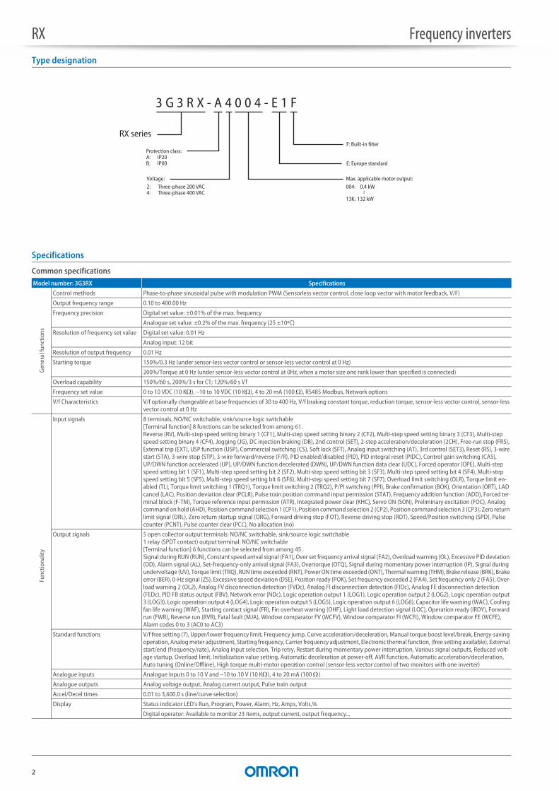
Type designation
Specifications
Common specificationsModel number: 3G3RX Specifications
Gen
eral
func
tions
Control methods Phase-to-phase sinusoidal pulse with modulation PWM (Sensorless vector control, close loop vector with motor feedback, V/F)
Output frequency range 0.10 to 400.00 Hz
Frequency precision Digital set value: ±0.01% of the max. frequency
Analogue set value: ±0.2% of the max. frequency (25 ±10ºC)
Resolution of frequency set value Digital set value: 0.01 Hz
Analog input: 12 bit
Resolution of output frequency 0.01 Hz
Starting torque 150%/0.3 Hz (under sensor-less vector control or sensor-less vector control at 0 Hz)
200%/Torque at 0 Hz (under sensor-less vector control at 0Hz, when a motor size one rank lower than specified is connected)
Overload capability 150%/60 s, 200%/3 s for CT; 120%/60 s VT
Frequency set value 0 to 10 VDC (10 K), –10 to 10 VDC (10 K), 4 to 20 mA (100 ), RS485 Modbus, Network options
V/f Characteristics V/f optionally changeable at base frequencies of 30 to 400 Hz, V/f braking constant torque, reduction torque, sensor-less vector control, sensor-less vector control at 0 Hz
Func
tiona
lity
Input signals 8 terminals, NO/NC switchable, sink/source logic switchable[Terminal function] 8 functions can be selected from among 61.Reverse (RV), Multi-step speed setting binary 1 (CF1), Multi-step speed setting binary 2 (CF2), Multi-step speed setting binary 3 (CF3), Multi-step speed setting binary 4 (CF4), Jogging (JG), DC injection braking (DB), 2nd control (SET), 2-step acceleration/deceleration (2CH), Free-run stop (FRS), External trip (EXT), USP function (USP), Commercial switching (CS), Soft lock (SFT), Analog input switching (AT), 3rd control (SET3), Reset (RS), 3-wire start (STA), 3-wire stop (STP), 3-wire forward/reverse (F/R), PID enabled/disabled (PID), PID integral reset (PIDC), Control gain switching (CAS), UP/DWN function accelerated (UP), UP/DWN function decelerated (DWN), UP/DWN function data clear (UDC), Forced operator (OPE), Multi-step speed setting bit 1 (SF1), Multi-step speed setting bit 2 (SF2), Multi-step speed setting bit 3 (SF3), Multi-step speed setting bit 4 (SF4), Multi-step speed setting bit 5 (SF5), Multi-step speed setting bit 6 (SF6), Multi-step speed setting bit 7 (SF7), Overload limit switching (OLR), Torque limit en-abled (TL), Torque limit switching 1 (TRQ1), Torque limit switching 2 (TRQ2), P/PI switching (PPI), Brake confirmation (BOK), Orientation (ORT), LAD cancel (LAC), Position deviation clear (PCLR), Pulse train position command input permission (STAT), Frequency addition function (ADD), Forced ter-minal block (F-TM), Torque reference input permission (ATR), Integrated power clear (KHC), Servo ON (SON), Preliminary excitation (FOC), Analog command on hold (AHD), Position command selection 1 (CP1), Position command selection 2 (CP2), Position command selection 3 (CP3), Zero return limit signal (ORL), Zero return startup signal (ORG), Forward driving stop (FOT), Reverse driving stop (ROT), Speed/Position switching (SPD), Pulse counter (PCNT), Pulse counter clear (PCC), No allocation (no)
Output signals 5 open collector output terminals: NO/NC switchable, sink/source logic switchable1 relay (SPDT contact) output terminal: NO/NC switchable[Terminal function] 6 functions can be selected from among 45.Signal during RUN (RUN), Constant speed arrival signal (FA1), Over set frequency arrival signal (FA2), Overload warning (OL), Excessive PID deviation (OD), Alarm signal (AL), Set-frequency-only arrival signal (FA3), Overtorque (OTQ), Signal during momentary power interruption (IP), Signal during undervoltage (UV), Torque limit (TRQ), RUN time exceeded (RNT), Power ON time exceeded (ONT), Thermal warning (THM), Brake release (BRK), Brake error (BER), 0-Hz signal (ZS), Excessive speed deviation (DSE), Position ready (POK), Set frequency exceeded 2 (FA4), Set frequency only 2 (FA5), Over-load warning 2 (OL2), Analog FV disconnection detection (FVDc), Analog FI disconnection detection (FIDc), Analog FE disconnection detection (FEDc), PID FB status output (FBV), Network error (NDc), Logic operation output 1 (LOG1), Logic operation output 2 (LOG2), Logic operation output 3 (LOG3), Logic operation output 4 (LOG4), Logic operation output 5 (LOG5), Logic operation output 6 (LOG6), Capacitor life warning (WAC), Cooling fan life warning (WAF), Starting contact signal (FR), Fin overheat warning (OHF), Light load detection signal (LOC), Operation ready (IRDY), Forward run (FWR), Reverse run (RVR), Fatal fault (MJA), Window comparator FV (WCFV), Window comparator FI (WCFI), Window comparator FE (WCFE), Alarm codes 0 to 3 (AC0 to AC3)
Standard functions V/f free setting (7), Upper/lower frequency limit, Frequency jump, Curve acceleration/deceleration, Manual torque boost level/break, Energy-saving operation, Analog meter adjustment, Starting frequency, Carrier frequency adjustment, Electronic thermal function, (free setting available), External start/end (frequency/rate), Analog input selection, Trip retry, Restart during momentary power interruption, Various signal outputs, Reduced volt-age startup, Overload limit, Initialization value setting, Automatic deceleration at power-off, AVR function, Automatic acceleration/deceleration, Auto tuning (Online/Offline), High torque multi-motor operation control (sensor-less vector control of two monitors with one inverter)
Analogue inputs Analogue inputs 0 to 10 V and –10 to 10 V (10 K), 4 to 20 mA (100 )
Analogue outputs Analog voltage output, Analog current output, Pulse train output
Accel/Decel times 0.01 to 3,600.0 s (line/curve selection)
Display Status indicator LED’s Run, Program, Power, Alarm, Hz, Amps, Volts,%
Digital operator: Available to monitor 23 items, output current, output frequency...
RX series
Protection class:A: IP20 B: IP00
3 G 3 R X - A 4 0 0 4 - E 1 F
Voltage:2: Three-phase 200 VAC4: Three-phase 400 VAC
Max. applicable motor output:004: 0,4 kW ~13K: 132 kW
E: Europe standard
F: Built-in filter

RX Frequency inverters
3
3G3RX 200 V class
3G3RX 400 V class
Prot
ectio
n fu
nctio
ns
Motor overload protection Electronic Thermal overload relay and PTC thermistor input
Instantaneous overcurrent 200% of rated current for 3 seconds
Overload 150% for 1 minute
Overvoltage 800 V for 400 V type and 400 V for 200 V type
Momentary power loss Decelerates to stop with DC bus controlled, coast to stop
Cooling fin overheat Temperature monitor and error detection
Stall prevention level Stall prevention during acceleration, deceleration and constant speed
Ground fault Detection at power on
Power charge indication On when voltage between P and N is higher than 45V
Ambi
ent c
ondi
tions
Degree of protection IP20/IP00
Ambient humidity 90% RH or less (without condensation)
Storage temperature –20 to 65°C (short-term temperature during transportation)
Ambient temperature –10 to 50°C
Installation Indoor (no corrosive gas, dust, etc.)
Installation height Max. 1,000 m
Vibration 3G3RX-A_004 to A_220, 5.9 m/s2 (0.6G), 10 to 55 Hz3G3RX-A_300 to B_13K, 2.94 m/s2 (0.3G), 10 to 55 Hz
Three-phase: 3G3RX-_ A2004 A2007 A2015 A2022 A2037 A2055 A2075 A2110 A2150 A2185 A2220 A2300 A2370 A2450 A2550
Max. applicable motor 4P kW*1
*1 Based on a standard 3-Phase motor.
at CT 0.4 0.75 1.5 2.2 3.7 5.5 7.5 11 15 18.5 22 30 37 45 55
at VT 0.75 1.5 2.2 3.7 5.5 7.5 11 15 18.5 22 30 37 45 55 75
Out
put
char
acte
ristic
s
Inverter capacity kVA
200 V at CT 1.0 1.7 2.5 3.6 5.7 8.3 11.0 15.9 22.1 26.3 32.9 41.9 50.2 63.0 76.2
at VT 1.3 2.1 3.2 4.1 6.7 10.4 15.2 20.0 26.3 29.4 39.1 49.5 59.2 72.7 93.5
240 V at CT 1.2 2.0 3.1 4.3 6.8 9.9 13.3 19.1 26.6 31.5 39.4 50.2 60.2 75.6 91.4
at VT 1.5 2.6 3.9 5.0 8.1 12.4 18.2 24.1 31.5 35.3 46.9 59.4 71.0 87.2 112.2
Rated output current (A) at CT 3.0 5.0 7.5 10.5 16.5 24 32 46 64 76 95 121 145 182 220
at VT 3.7 6.3 9.4 12 19.6 30 44 58 73 85 113 140 169 210 270
Max. output voltage Proportional to input voltage: 0 to 240 V
Max. output frequency 400 Hz
Pow
ersu
pply Rated input voltage and frequency 3-phase 200 to 240 V 50/60 Hz
Allowable voltage fluctuation –15% to 10%
Allowable frequency fluctuation 5%
Pow
ersu
pply Regenerative braking Internal BRD circuit (external discharge resistor) External regenerative braking unit
Minimum connectable resistance 50 50 35 35 35 16 10 10 7.5 7.5 5
Degree of protection IP20
Cooling method Forced air cooling
Three-phase: 3G3RX-_ A4004 A4007 A4015 A4022 A4040 A4055 A4075 A4110 A4150 A4185 A4220 A4300 A4370 A4450 A4550 B4750 B4900 B411K B413K
Max. applicable motor 4P kW*1
*1 Based on a standard 3-Phase motor.
at CT 0.4 0.75 1.5 2.2 4.0 5.5 7.5 11 15 18.5 22 30 37 45 55 75 90 110 132
at VT 0.75 1.5 2.2 4.0 5.5 7.5 11 15 18.5 22 30 37 45 55 75 90 110 132 160
Out
put
char
acte
ristic
s
Inverter capacity kVA
400 V at CT 1.0 1.7 2.5 3.6 6.2 9.7 13.1 17.3 22.1 26.3 33.2 40.1 51.9 63.0 77.6 103.2 121.9 150.3 180.1
at VT 1.3 2.1 3.3 4.6 7.7 11.0 15.2 20.9 25.6 30.4 39.4 48.4 58.8 72.7 93.5 110.8 135 159.3 200.9
480 V at CT 1.2 2.0 3.1 4.3 7.4 11.6 15.8 20.7 26.6 31.5 39.9 48.2 62.3 75.6 93.1 123.8 146.3 180.4 216.1
at VT 1.5 2.5 4.0 5.5 9.2 13.3 18.2 24.1 30.7 36.5 47.3 58.1 70.6 87.2 112.2 133 162.1 191.2 241.1
Rated output current (A) at CT 1.5 2.5 3.8 5.3 9.0 14 19 25 32 38 48 58 75 91 112 149 176 217 260
at VT 1.9 3.1 4.8 6.7 11.1 16 22 29 37 43 57 70 85 105 135 160 195 230 290
Max. output voltage Proportional to input voltage: 0 to 480 V
Max. output frequency 400 Hz
Pow
ersu
pply Rated input voltage and frequency 3-phase 380 to 480 V 50/60 Hz
Allowable voltage fluctuation –15% to 10%
Allowable frequency fluctuation 5%
Pow
ersu
pply Regenerative braking Internal BRD circuit (external discharge resistor) External regenerative braking unit
Minimum connectable resistance 100 100 100 100 70 70 35 35 24 24 20
Degree of protection IP20 IP00
Cooling method Forced air cooling
Model number: 3G3RX Specifications
RX Frequency inverters
4
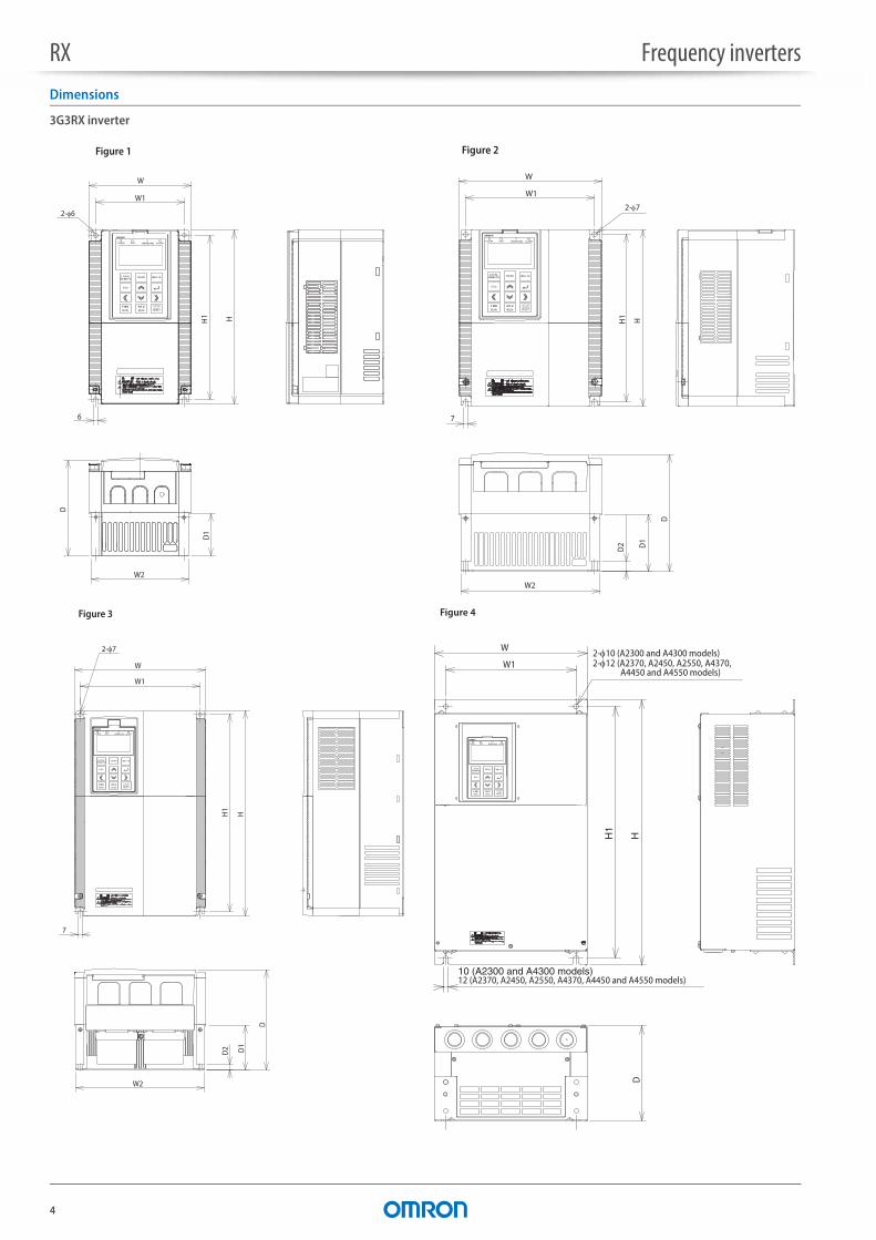
Dimensions
3G3RX inverter
W
2-6
W1
W2
6
D
D1
H1 H
Figure 1
FWD REV
WARNING
READ WRITE
ESC
LOCALREMOTE
W1
7
W2
D2 D1
H1
H
2-7
W
D
LOCALREMOTE
FWD REV
WARNING
READ WRITE
ESC
Figure 3
W
10 (A2300 and A4300 models)12 (A2370, A2450, A2550, A4370, A4450 and A4550 models)
H1
H
2-10 (A2300 and A4300 models)2-12 (A2370, A2450, A2550, A4370,
A4450 and A4550 models)
D
W1
LOCALREMOTE
FWD REV
WARNING
READ WRITE
ESC
Figure 4
W2
D1
D2
2-7
W1
7
H1 H
W
D
LOCALREMOTE
FWD REV
WARNING
READ WRITE
ESC
Figure 2
RX Frequency inverters
5
Voltage class Inverter model Figure Dimensions in mm
W W1 W2 H H1 D D1 D2 Weight (kg)
Three-phase 200 V 3G3RX-A2004 1 150 130 143 255 241 140 62 – 3.53G3RX-A2007
3G3RX-A2015
3G3RX-A2022
3G3RX-A2037
3G3RX-A2055 2 210 189 203 260 246 170 82 13.6 63G3RX-A2075
3G3RX-A2110
3G3RX-A2150 3 250 229 244 390 376 190 83 9.5 143G3RX-A2185
3G3RX-A2220
3G3RX-A2300 4 310 265 – 540 510 195 – – 20
3G3RX-A2370 390 300 – 550 520 250 – – 303G3RX-A2450
3G3RX-A2550 480 380 – 700 670 250 – – 43
Three-phase 400 V 3G3RX-A4004 1 150 130 143 255 241 140 62 – 3.53G3RX-A4007
3G3RX-A4015
3G3RX-A4022
3G3RX-A4040
3G3RX-A4055 2 210 189 203 260 246 170 82 13.6 63G3RX-A4075
3G3RX-A4110
3G3RX-A4150 3 250 229 244 390 376 190 83 9.5 143G3RX-A4185
3G3RX-A4220
3G3RX-A4300 4 310 265 – 540 510 195 – – 22
3G3RX-A4370 390 300 – 550 520 250 – – 303G3RX-A4450
3G3RX-A4550
3G3RX-B4750 5 390 300 – 700 670 270 – – 603G3RX-B4900
3G3RX-B411K 480 380 – 740 710 270 – – 803G3RX-B413K
2-12
12
W1
W
DH H1
Figure 5
LOCALREMOTE
FWD REV
WARNING
READ WRITE
ESC
RX Frequency inverters
6
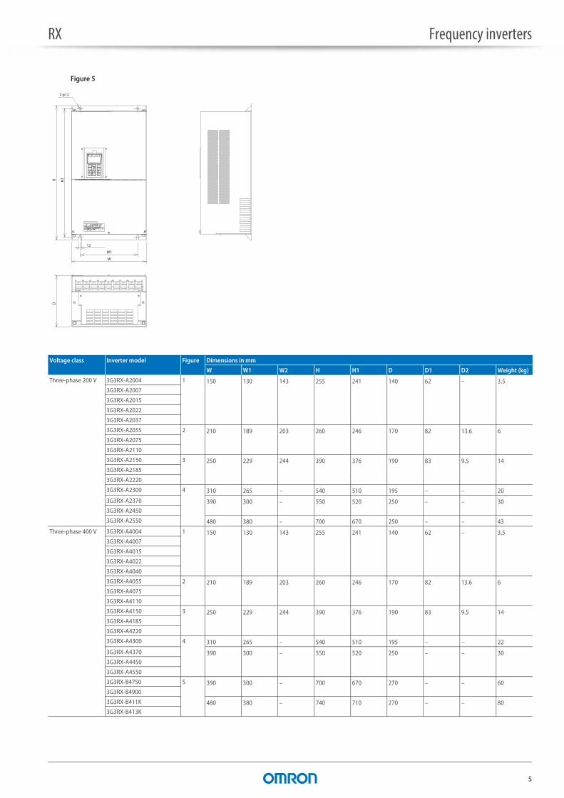
Rasmi filters
Voltage class Inverter model Rasmi model Filter type Dimensions in mm
L W H X Y M Weight (kg)
3-phase 200 V 3G3RX-A2004 AX-FIR2018-RE Footprint 305 152 45 290 110 M5 2.03G3RX-A2007
3G3RX-A2015
3G3RX-A2022
3G3RX-A2037
3G3RX-A2055 AX-FIR2053-RE 320 212 56 296 189 M6 2.53G3RX-A2075
3G3RX-A2110
3G3RX-A2150 AX-FIR2110-RE Book 455 110 240 414 80 8.03G3RX-A2185
3G3RX-A2220
3G3RX-A2300 AX-FIR2145-RE 8.6
3G3RX-A2370 AX-FIR3250-RE Block 386 260 135 240 235 – 133G3RX-A2450
3G3RX-A2550 AX-FIR3320-RE 13.2
3-phase 400 V 3G3RX-A4004 AX-FIR3010-RE Footprint 305 152 45 290 110 M5 1.43G3RX-A4007
3G3RX-A4015
3G3RX-A4022
3G3RX-A4040
3G3RX-A4055 AX-FIR3030-RE 312 212 50 296 189 M6 2.23G3RX-A4075
3G3RX-A4110
3G3RX-A4150 AX-FIR3053-RE 451 252 60 435 229 M6 4.53G3RX-A4185
3G3RX-A4220
3G3RX-A4300 AX-FIR3064-RE 598 310 70 578 265 M8 7.0
3G3RX-A4370 AX-FIR3100-RE Book 486 110 240 414 80 – 8.0
3G3RX-A4450 AX-FIR3130-RE 8.63G3RX-A4550
3G3RX-B4750 AX-FIR3250-RE Block 386 260 135 240 235 – 13.03G3RX-B4900
3G3RX-B411K AX-FIR3320-RE 13.23G3RX-B413K
drive mounts
WH
Y
XL
outputflexes
W H
Y
XL
Y
WH
L X
Footprint dimensions Book type dimensions Block type dimensions
RX Frequency inverters
7
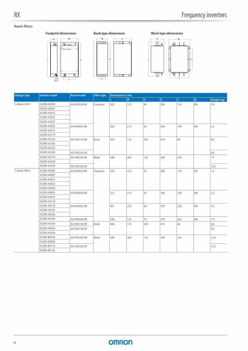
Input AC reactor
DC reactor
Voltage class Reference Dimensions in mm
A B1 B2 C1 C2 D E F Weight (kg)
3-phase 200 V AX-RAI02800080-DE 120 – 70 – 120 80 52 5.5 1.78
AX-RAI00880200-DE 80 62 2.35
AX-RAI00350335-DE 180 85 190 140 55 6 5.5
AX-RAI00180670-DE
AX-RAI00091000-DE 205 6.5
AX-RAI00071550-DE 105 85 11.7
AX-RAI00042300-DE 120 – 150 –
3-phase 400 V AX-RAI07700050-DE 120 – 70 – 120 80 52 5.5 1.78
AX-RAI03500100-DE 80 62 2.35
AX-RAI01300170-DE 180 75 195 140 55 6 5.5
AX-RAI00740335-DE 85 190
AX-RAI00360500-DE 205 6.5
AX-RAI00290780-DE 105 75 11.2
AX-RAI00191150-DE 240 110 275 200 16.0
AX-RAI00111850-DE
AX-RAI00072700-DE 180 – 210 – 110 25.4
Voltage class Reference Fig Dimensions in mm
A B C D E F G H Weight (kg)
3-phase 200 V AX-RC10700032-DE 1 84 113 96 101 66 5 7.5 2 1.22
AX-RC06750061-DE 105 1.60
AX-RC03510093-DE
AX-RC02510138-DE 116 1.95
AX-RC01600223-DE 108 135 124 120 82 6.5 9.5 9.5 3.20
AX-RC01110309-DE 120 152 136 135 94 7 – 5.20
AX-RC00840437-DE 146 6.00
AX-RC00590614-DE 150 177 160 160 115 2 11.4
AX-RC00440859-DE 183 14.3
AX-RC00301275-DE 2 195 161 163 185 88 10 – – 17.0
AX-RC00231662-DE 196 123 25.5
AX-RC00192015-DE 240 188 200 228 109 12 34.0
AX-RC00162500-DE 198 119 38.0
AX-RC00133057-DE 228 149 42.0
Figure 1
C
D
A
F
E
B
Figure 2

RX Frequency inverters
8
Output AC reactor
3-phase 400 V AX-RC43000020-DE 1 84 113 96 101 66 5 7.5 2 1.22
AX-RC27000030-DE 105 1.60
AX-RC14000047-DE
AX-RC10100069-DE 116 1.95
AX-RC06400116-DE 108 135 133 120 82 6.5 9.5 9.5 3.70
AX-RC04410167-DE 120 152 136 135 94 7 – 5.20
AX-RC03350219-DE 146 6.00
AX-RC02330307-DE 150 177 160 160 115 7 2 11.4
AX-RC01750430-DE 183 14.3
AX-RC01200644-DE 2 195 161 163 185 88 10 – – 17.0
AX-RC00920797-DE 196 123 25.5
AX-RC00741042-DE 240 188 200 228 109 12 34.0
AX-RC00611236-DE 198 119 38.0
AX-RC00501529-DE 228 149 48.0
AX-RC00372094-DE
AX-RC00312446-DE 300 230 256 250 160 49.0
AX-RC00252981-DE 245 52.5
AX-RC00213613-DE 250 180 79.0
Voltage class Reference Dimensions in mm
A B1 B2 C1 C2 D E F Weight (kg)
3-phase 200 V AX-RAO11500026-DE 120 – 70 – 120 80 52 5.5 1.78
AX-RAO07600042-DE 120 – 70 – 120 80 52 5.5 1.78
AX-RAO04100075-DE 120 – 80 – 120 80 62 5.5 2.35
AX-RAO03000105-DE 120 – 80 – 120 80 62 5.5 2.35
AX-RAO01830160-DE 180 – 85 – 190 140 55 6 5.5
AX-RAO01150220-DE 180 – 85 – 190 140 55 6 5.5
AX-RAO00950320-DE 180 – 85 – 205 140 55 6 6.5
AX-RAO00630430-DE 180 – 95 – 205 140 65 6 9.1
AX-RAO00490640-DE 180 – 95 – 205 140 65 6 9.1
AX-RAO00390800-DE 240 – 110 – 275 200 75 6 16.0
AX-RAO00330950-DE 240 – 110 – 275 200 75 6 16.0
AX-RAO00251210-DE 240 – 110 – 275 200 75 6 16.0
AX-RAO00191450-DE 240 – 120 – 275 200 85 6 18.6
AX-RAO00161820-DE 240 – 150 – 275 200 110 6 27.0
AX-RAO00132200-DE 300 – 145 – 320 200 125 6 33.5
Voltage class Reference Fig Dimensions in mm
A B C D E F G H Weight (kg)
RX Frequency inverters
9
Chokes
DC Supply with Regenerative Active Front End
Regenerative DC bus supply
3-phase 400 V AX-RAO16300038-DE 120 – 80 – 120 80 62 5.5 2.35
AX-RAO11800053-DE 120 – 80 – 120 80 62 5.5 2.35
AX-RAO07300080-DE 180 – 85 – 190 140 55 6 5.5
AX-RAO04600110-DE 180 – 85 – 190 140 55 6 5.5
AX-RAO03600160-DE 180 – 85 – 205 140 55 6 6.5
AX-RAO02500220-DE 180 – 95 – 205 140 65 6 9.1
AX-RAO02000320-DE 240 – 110 – 275 200 75 6 16.0
AX-RAO01650400-DE 240 – 110 – 275 200 75 6 16.0
AX-RAO01300480-DE 240 – 110 – 275 200 75 6 16.0
AX-RAO01030580-DE 240 – 110 – 275 200 75 6 16.0
AX-RAO00800750-DE 240 – 120 – 275 200 85 6 18.6
AX-RAO00680900-DE 240 – 150 – 275 200 110 6 27.0
AX-RAO00531100-DE 300 – 125 – 330 200 105 6 27.9
AX-RAO00401490-DE 300 – 165 – 330 200 125 6 44.0
AX-RAO00331760-DE 300 – 165 – 330 200 125 6 44.0
AX-RAO00262170-DE 360 230 – 315 – 300 150 8 55.0
AX-RAO00212600-DE 420 255 – 360 – 300 145 8 102.0
Reference Diameter Motor kW Dimensions in mm
L W H X Y m Weight (kg)
AX-FER2102-RE 21 <2.2 85 22 46 70 – 5 0.1
AX-FER2515-RE 25 <15 105 25 62 90 – 5 0.2
AX-FER5045-RE 50 <45 150 50 110 125 30 5 0.7
AX-FER6055-RE 60 ³55 200 65 170 180 45 6 1.7
Reference Fig Weight (kg)
RFE-B3 30-400-50-230-A-RVE 1 37
RFE-B3 45-400-50-230-A-RVE 38
RFE-B3 60-400-50-230-A-RVE 2 45
RFE-B3 80-400-50-230-A-RVE 52
RFE-B3 100-400-50-230-A-RVE 65
RFE-B3 125-400-50-230-A-RVE 3 87
RFE-B3 150-400-50-230-A-RVE 89
RFE-B3 200-400-50-230-A-RVE 100
Voltage class Reference Dimensions in mm
A B1 B2 C1 C2 D E F Weight (kg)
X
H
YW Ø m
L
Ø d
269251 311,5
581,
64 498
Figure 1
238
305
273254,4
590
703
753,
67
Figure 2
378
349,2389,5
319
888,
9
279
838
Figure 3
RX Frequency inverters
10
Low harmonic filter
EMC filter
Reference Fig Weight (kg)
RHF-RA 43-400-50-20-A-RVE 1 39
RHF-RA 72-400-50-20-A-RV 2 56
RHF-RA 86-400-50-20-A-RVE 3 62
RHF-RA 144-400-50-20-A-RVE 4 85
RHF-RA 180-400-50-20-A-RVE 102
RHF-RA 217-400-50-20-A-RVE 5 119
RHF-RA 304-400-50-20-A-RVE 142
Reference Fig Filter type Weight (kg)
RFI-RA 12-RVE 1 Footprint 11,1
RFI-RA 23-RVE 2 15,1
RFI-RA X5-RVE 3 Book 4,9
RFI-RA X6-RVE 4 Block 3,9
460
145 233 145
547549
590
9
9
353
378
244
PEM8
X1 mains 16mm2
X2 drive 16mm2
X3/X4 capacitor disconnect 10mm2
A/B temperature 2,5mm2
Figure 1
489
577579
619
9
353
378
9
54,3
157 240 157
338
PEM8
X1 mains 35mm2 X2 drive 35mm2
X3/X4 capacitor disconnect 16mm2
A/B temperature 2,5mm2
Figure 2 Figure 3
597
685
736,8
9
393
9
63,8
210,5 240 210,5
336,
3
PEM8
X2 drive 50mm2
X3/X4 capacitor disconnect 16mm2
A/B temperature 2,5mm2
X1 mains 50mm2
597
685
767,3
9
393
9
94 210,5 240 210,5
405,
3
PEM8
X2 drive 50mm2
X3/X4 capacitor disconnect 16mm2
A/B temperature 2,5mm2
X1 mains 50mm2
Figure 4
715
800
948,5
9
443
9
158,5 240 300 240
450,
5
PEM12
X2 drive 300mm2
X3/X4 capacitor disconnect 120mm2
A/B temperature 2,5mm2X1 mains 300mm2
Figure 5
Figure 1 Figure 2
200
208
268
8990
Figure 3 Figure 4
700
75
780
755
245
3018
034
015
0
256
312
320
112
312
214,5
224
500
75
555
245
260
340
80

RX Frequency inverters
11
Regenerative Braking unit
Models for Low Duty applications (50%) Fig Weight (kg) Models for High Duty applications Fig Weight (kg)
RLD-E0 8-400-50-0-A-RVE 1 16 RHD-B0 7-400-50-0-A-RVE 1 17
RLD-E0 12-400-50-0-A-RVE 17 RHD-B0 13-400-50-0-A-RVE 18
RLD-E0 16-400-50-0-A-RVE 18 RHD-B0 18-400-50-0-A-RVE 20
RLD-E0 20-400-50-0-A-RVE RHD-B0 24-400-50-0-A-RVE 3 32,5
RLD-E0 24-400-50-0-A-RVE 2 RHD-B0 30-400-50-230-A-RVE
RLD-E0 32-400-50-0-A-RVE 22 RHD-B0 50-400-50-230-A-RVE 5 40
RLD-E0 40-400-50-0-A-RVE 23 RHD-B0 70-400-50-230-A-RVE 51
RLD-E0 48-400-50-0-A-RVE 4 27 RHD-B0 100-400-50-230-A-RVE 7 85
RLD-E0 58-400-50-0-A-RVE 28 RHD-B0 125-400-50-230-A-RVE 91
RLD-E0 80-400-50-0-A-RVE 30 RHD-B0 150-400-50-230-A-RVE 100
RLD-E0 95-400-50-0-A-RVE 35
RLD-E0 116-400-50-0-A-RVE 38
RLD-E0 140-400-50-0-A-RVE 6 52
RLD-E0 170-400-50-230-A-RVE 60
RLD-E0 200-400-50-230-A-RVE 68
269251 311,5
581,
64 498
Figure 1 Figure 2
378
349,2389,5
319
888,
9
279
838
Figure 3
Figure 7Figure 6
Figure 4
240
211240
365
384
414,
8
340
240
246,4
275
410,
9
211
493,
8
449
430
504
256
314,8226
529
611,
4
530
214,5
835,
7
731,
5
256
320
722
703,
5
Figure 5
238
305
273254,4
590
703
753,
67
RX Frequency inverters
12
Braking unit
Resistor
Reference Dimensions in mm
B B1 H H1 T S
AX-BCR4015045-TE 82.5 40.5 150 138 220 6
AX-BCR4017068-TE
AX-BCR2035090-TE 130 64.5 205 193 208 6
AX-BCR2070130-TE
AX-BCR4035090-TE
AX-BCR4070130-TE
AX-BCR4090240-TE 131 64.5 298 280 300 9
Reference Fig Dimensions in mm
L H M I T G N Weight (kg)
AX-REM00K2070-IE 1 105 27 36 94 – – – 0.2
AX-REM00K2120-IE
AX-REM00K2200-IE
AX-REM00K4075-IE 200 27 36 189 – – – 0.425
AX-REM00K4035-IE
AX-REM00K4030-IE
AX-REM00K5120-IE 260 27 36 249 – – – 0.58
AX-REM00K6100-IE 320 27 36 309 – – – 0.73
AX-REM00K6035-IE
AX-REM00K9070-IE 2 200 61 100 74.5 216 40 230 1.41
AX-REM00K9020-IE
AX-REM00K9017-IE
AX-REM01K9070-IE 3 365 73 105 350 70 – – 4
AX-REM01K9017-IE
AX-REM02K1070-IE 4 310 100 240 295 210 – – 7
AX-REM02K1017-IE
AX-REM03K5035-IE 365 100 240 350 210 – – 8
AX-REM03K5010-IE
AX-REM19K0006-IE 5 206 350 140 190 50 – – 8.1
AX-REM19K0008-IE
AX-REM19K0020-IE
AX-REM19K0030-IE
AX-REM38K0012-IE 306 350 140 290 50 – – 14.5
SB
H1
TB1
H
ACTIVEPOWER
OVERCURRENT
BU
SS
BU
SS
+
R R
BC...C H O PP ER
DANGERHIGH VOLTAGE !
168
13
45
20
182
AX-REM00K15xxx Fig 1 Fig 2
Fig 3 Fig 4 Fig 5

RX Frequency inverters
13
Installation
Standard connections
*1 L is the common reference for analog input and also for the analog output.
Terminal connections
Terminal Name Function (signal level)
R/L1, S/L2, T/L3 Main circuit power supply input Used to connect line power to the drive
U/T1, V/T2, W/T3 Inverter output Used to connect the motor
PD/+1, P/+ External DC reactor terminal Normally connected by the short-circuit bar. Remove the short-circuit bar between +1 and P/+2 when a DC reactor is connected
P/+, RB Braking resistor connection terminal Connect option braking resistor (if a braking torque is required)
P/+, N/- Regenerative braking unit connection terminal Connect optional regenerative braking units
PE Grounding For grounding (grounding should conform to the local grounding code)
DC reactor (optional)
3-phase 200 VAC3-phase 400 VAC
Multi-function input 1
Multi-function input 2
Multi-function input 3
Multi-function input 4
Multi-function input 5
Multi-function input 6
Multi-function input 7
Multi-function input 8
Frequency setting unit500 to 2 k
Sequence input common
M
R/L1PD/+1 P/+
Braking resistor (optional)
RBN/–
T/L3
R
T
Ro
To
S/L2
U/T1
W/T3
12Multi-function output 2
13Multi-function output 3
14Multi-function output 4
15Multi-function output 5
CM2
SP
SN
RP
SN
AM
AMI
FM
Option 1
Option 2
Multi-function output common
11Multi-function output 1
Relay output
Common
V/T2
1
FW
PLC
CM1
4
P24
CM1
ThermistorTH
H
OI
L*1
O
O2
3
2
5
RS485 communication
6
7
8
Short-circuit wire
To wire the control circuit power supply and main circuit power supply separately, be sure to remove the J51 connector wire first.
Control circuit power supply
J51
For termination resistors
Analog monitor output (voltage output)
Analog monitor output (current output)
Digital monitor output (PWM output)
AL1
AL2
AL0
DC24V
DC10V10k
10k
10k
Frequency reference power supplyFrequency reference input(voltage)
Frequency referenceauxiliary input (voltage)
Frequency reference input(current)
Frequency referencecommon
*1
RX Frequency inverters
14
Control circuitType No. Signal name Function (default) Signal level
Freq
uenc
y re
fere
nce
inpu
t
H Frequency reference power supply 10 VDC 20 mA max
O Voltage frequency reference input 0 to 12 VDC (10 k)
O2 Voltage auxiliary frequency reference 0 to ±12 VDC (10 k)
OI Current frequency reference input 4 to 20 mA (100 )
L Frequency reference common Common terminal for analog monitor (AM, AMI) terminals
Mon
itor
outp
ut
AM Multi-function analog voltage output Factory setting: Output frequency 2 mA max
AMI Multi-function analog current output Factory setting: Output frequency 4 to 20 mA (max imp 250 )
FM PWM monitor output Factory setting: Output frequency 0 to 10 VDC (max 3.6 kHz)
Pow
er
supp
ly P24 Internal 24 VDC Power supply for contact input signal 100 mA max
CM1 Input common Common terminal for P24, TH and FM digital monitor
Func
tion
sele
ctio
n
FW Forward rotation command terminal Motor runs in forwards direction when FW is ON 27 VDC max Input imped 4.7 kmax current 5.6 mA On: 18 VDC or more
1 Multi-function input Factory setting: Reverse (RV)
2 Factory setting: External trip (EXT)
3 Factory setting: Reset (RS)
4 Factory setting: Multi-step speed reference 1 (CF1)
5 Factory setting: Multi-step speed reference 2 (CF2)
6 Factory setting: Jogging (JG)
7 Factory setting: Second control (SET)
8 Factory setting: No allocation (NO)
PLC Multi-function input common Sink logic: Short-circuiting P24 and PLCSource logic: Short-circuiting PLC and CM1With external supply remove short-circuit bar
Stat
us/F
acto
r
11 Multi-function output Factory setting: During Run (RUN) 27 VDC max 50 mA max
12 Factory setting: 0 Hz signal (ZS)
13 Factory setting: Overload warning (OL)
14 Factory setting: Overtorque (OTQ)
15 Factory setting: Constant speed arrival (FA1)
CM2 Multi-function output common Common terminal for multi-function output terminals 11 to 15
Rela
y ou
tput
AL1 Relay output (Normally close) Factory setting: Alarm output (AL)
Under normal operation
MA-MC open
MB-MC close
R load
AL1-AL0
250 VAC 2 A
AL2-AL0
250 VAC 1 A
I load
250 VAC 0.2 A
AL2 Relay output (Normally open)
AL0 Relay output common
Sensor
TH External thermistor input terminal SC terminal functions as the common terminal
100 m minimum
Impedance at temperature error: 3 kW
0 to 8 VDC
Com
ms
SP RS485 Modbus terminals – Differential input
SN
RP RS485 terminating resistor terminals – –
SN

RX Frequency inverters
15
Inverter heat loss
3G3RX 200 V class
3G3RX 400 V class
Input AC reactor
DC reactor
Three-phase: 3G3RX-_ A2004 A2007 A2015 A2022 A2037 A2055 A2075 A2110 A2150 A2185 A2220 A2300 A2370 A2450 A2550
Inverter capacity kVA 200 V 1.0 1.7 2.5 3.6 5.7 8.3 11.0 15.9 22.1 26.3 32.9 41.9 50.2 63.0 76.2
400 V 1.2 2.0 3.1 4.3 6.8 9.9 13.3 19.1 26.6 31.5 39.4 50.2 60.2 75.6 91.4
Rated output current A 3.0 5.0 7.5 10.5 16.5 24 32 46 64 76 95 121 145 182 220
Heat loss W Losses at 70% load 64 76 102 127 179 242 312 435 575 698 820 1,100 1,345 1,625 1,975
Losses at 100% load 70 88 125 160 235 325 425 600 800 975 1,150 1,550 1,900 2,300 2,800
Efficiency at rated output 85.1 89.5 92.3 93.2 94.0 94.4 94.6 94.8 94.9 95.0 95.0 95.0 95.1 95.1 95.1
Cooling method Forced air cooling
Three-phase: 3G3RX-_ A4004 A4007 A4015 A4022 A4040 A4055 A4075 A4110 A4150 A4185 A4220 A4300 A4370 A4450 A4550 B4750 B4900 B411K B413K
Inverter capacity kVA 200 V 1.0 1.7 2.5 3.6 6.2 9.7 13.1 17.3 22.1 26.3 33.2 40.1 51.9 63.0 77.6 103.2 121.9 150.3 180.1
400 V 1.2 2.0 3.1 4.3 7.4 11.6 15.8 20.7 26.6 31.5 39.9 48.2 62.3 75.6 93.1 123.8 146.3 180.4 216.1
Rated output current A 1.5 2.5 3.8 5.3 9.0 14 19 25 32 38 48 58 75 91 112 149 176 217 260
Heat loss W Losses at 70% load 64 76 102 127 179 242 312 435 575 698 820 1,100 1,345 1,625 1,975 2,675 3,375 3,900 4,670
Losses at 100% load 70 88 125 160 235 325 425 600 800 975 1,150 1,550 1,900 2,300 2,800 3,800 4,800 5,550 6,650
Efficiency at rated output 85.1 89.5 92.3 93.2 94.0 64.4 94.6 94.8 94.9 95.0 95.0 95.0 95.1 95.1 95.1 95.2 95.2 95.2 95.2
Cooling method Forced air cooling
3-phase 200 V 3-phase 400 V
Max. applicable motor output kW
Reference Current value A Inductance mH Max. applicable motor output kW
Reference Current value A Inductance mH
0.4 to 1.5 AX-RAI02800080-DE 8.0 2.8 0.4 to 1.5 AX-RAI07700050-DE 5.0 7.7
2.2 to 3.7 AX-RAI00880200-DE 20.0 0.88 2.2 to 4.0 AX-RAI03500100-DE 10.0 3.5
5.5 to 7.5 AX-RAI00350335-DE 33.5 0.35 5.5 to 7.5 AX-RAI01300170-DE 17.0 1.3
11.0 to 15.0 AX-RAI00180670-DE 67.0 0.18 11.0 to 15.0 AX-RAI00740335-DE 33.5 0.74
18.5 to 22.0 AX-RAI00091000-DE 100.0 0.09 18.5 to 22.0 AX-RAI00360500-DE 50.0 0.36
30.0 to 37.0 AX-RAI00071550-DE 155.0 0.07 30.0 to 37.0 AX-RAI00290780-DE 78.0 0.29
45.0 to 55.0 AX-RAI00042300-DE 230.0 0.04 45.0 to 55.0 AX-RAI00191150-DE 115.0 0.19
75.0 to 90.0 AX-RAI00111850-DE 185.0 0.11
110.0 to 132.0 AX.RAI00072700-DE 270.0 0.07
3-phase 200 V 3-phase 400 V
Max. applicable motor output kW
Reference Current value A Inductance mH Max. applicable motor output kW
Reference Current value A Inductance mH
0.4 AX-RC10700032-DE 3.2 10.70 0.4 AX-RC43000020-DE 2.0 43.00
0.7 AX-RC06750061-DE 6.1 6.75 0.7 AX-RC27000030-DE 3.0 27.00
1.5 AX-RC03510093-DE 9.3 3.51 1.5 AX-RC14000047-DE 4.7 14.00
2.2 AX-RC02510138-DE 13.8 2.51 2.2 AX-RC10100069-DE 6.9 10.10
3.7 AX-RC01600223-DE 22.3 1.60 4.0 AX-RC06400116-DE 11.6 6.40
MCCBPower supply
AC reactor RX
R/L1U
V
W
X
Y
Z
S/L2
T/L3
Powersupply
RX
DC reactor
R/L1
PD/+1 P/+
MCCB
S/L2
T/L3
RX Frequency inverters
16
Output AC reactor
Braking unit
5.5 AX-RC01110309-DE 30.9 1.11 5.5 AX-RC04410167-DE 16.7 4.41
7.5 AX-RC00840437-DE 43.7 0.84 7.5 AX-RC03350219-DE 21.9 3.35
11.0 AX-RC00590614-DE 61.4 0.59 11.0 AX-RC02330307-DE 30.7 2.33
15.0 AX-RC00440859-DE 85.9 0.44 15.0 AX-RC01750430-DE 43.0 1.75
18.5 to 22 AX-RC00301275-DE 127.5 0.30 18.5 to 22 AX-RC01200644-DE 64.4 1.20
30 AX-RC00231662-DE 166.2 0.23 30 AX-RC00920797-DE 79.7 0.92
37 AX-RC00192015-DE 201.5 0.19 37 AX-RC00741042-DE 104.2 0.74
45 AX-RC00162500-DE 250.0 0.16 45 AX-RC00611236-DE 123.6 0.61
55 AX-RC00133057-DE 305.7 0.13 55 AX-RC00501529-DE 152.9 0.50
75 AX-RC00372094-DE 209.4 0.37
90 AX-RC00312446-DE 244.6 0.31
110 AX-RC00252981-DE 298.1 0.25
132 AX-RC00213613-DE 361.3 0.21
3-phase 200 V 3-phase 400 V
Max. applicable motor output kW
Reference Current value A Inductance mH Max. applicable motor output kW
Reference Current value A Inductance mH
0.4 AX-RAO11500026-DE 2.6 11.50 0.4 to 1.5 AX-RAO16300038-DE 3.8 16.30
0.75 AX-RAO07600042-DE 4.2 7.60
1.5 AX-RAO04100075-DE 7.5 4.10
2.2 AX-RAO03000105-DE 10.5 3.00 2.2 AX-RAO11800053-DE 5.3 11.80
3.7 AX-RAO01830160-DE 16.0 1.83 4.0 AX-RAO07300080-DE 8.0 7.30
5.5 AX-RAO01150220-DE 22.0 1.15 5.5 AX-RAO04600110-DE 11.0 4.60
7.5 AX-RAO00950320-DE 32.0 0.95 7.5 AX-RAO03600160-DE 16.0 3.60
11 AX-RAO00630430-DE 43.0 0.63 11 AX-RAO02500220-DE 22.0 2.50
15 AX-RAO00490640-DE 64.0 0.49 15 AX-RAO02000320-DE 32.0 2.00
18.5 AX-RAO00390800-DE 80.0 0.39 18.5 AX-RAO01650400-DE 40.0 1.65
22 AX-RAO00330950-DE 95.0 0.33 22 AX-RAO01300480-DE 48.0 1.30
30 AX-RAO00251210-DE 121.0 0.25 30 AX-RAO01030580-DE 58.0 1.03
37 AX-RAO00191450-DE 145.0 0.19 37 AX-RAO00800750-DE 75.0 0.80
45 AX-RAO00161820-DE 182.0 0.16 45 AX-RAO00680900-DE 90.0 0.68
55 AX-RAO00132200-DE 220.0 0.13 55 AX-RAO00531100-DE 110.0 0.53
75 AX-RAO00401490-DE 149.0 0.40
90 AX-RAO00331760-DE 176.0 0.33
110 AX-RAO00262170-DE 217.0 0.26
132 AX-RAO00212600-DE 260.0 0.21
Voltage Reference Specifications
Permanent Peak (5 s max) Minimum connectable resistor (Ohms)Current value A Brake power kVA Current value A Brake power kVA
3-phase 200 V AX-BCR2035090-TE 35 13 90 32 4
AX-BCR2070130-TE 70 25 130 47 2.8
3-phase 400 V AX-BCR4015045-TE 15 11 45 33 16
AX-BCR4017068-TE 17 13 68 51 11
AX-BCR4035090-TE 35 26 90 67 8.5
AX-BCR4070130-TE 70 52 130 97 5.5
AX-BCR4090240-TE 90 67 240 180 3.2
3-phase 200 V 3-phase 400 V
Max. applicable motor output kW
Reference Current value A Inductance mH Max. applicable motor output kW
Reference Current value A Inductance mH
RX Frequency inverters
17
DC Supply with Regenerative Active Front End system
Regenerative DC bus supply
Low harmonic filter
Reference: RFE-B3_ 30 45 60 80 100 125 150 200
Max. input power kW 30 45 60 80 100 125 150 200
DC capacity F 100 220 440 660
Max. input current A*1
*1 At nominal voltage 400 V. 1 min in 10 min.
Driving AC 65 98 130 173 217 271 325 433
DC 78 118 156 208 260 325 390 520
Braking AC 52 78 104 139 173 217 260 346
DC 62 97 125 167 208 260 312 415
Rated input voltage 3-phase 400 V
Allowable voltage fluctuation -15% to 10%
Mains frequency 40 to 60 Hz
Efficiency 98%
Degree of protection IP20
Ambient humidity 85% RH or less (without condensation)
Storage temperature –25 to 55°C
Ambient temperature 5 to 40°C
Reference: RHF-RA_ 43 72 86 144 180 217 304
IRMS current A*1 100% AC 43 72 86 144 180 217 304
150% AC1 min in 10 min
64,5 108 129 216 270 325,5 456
Heat loss W*1
*1 At nominal voltage 400 V, 50 Hz.
242 352 374 488 692 743 905
Allowable voltage fluctuation -15% to 10%
Power frequency 50 Hz
Efficiency 98,5-99,5%
Degree of protection IP20
Ambient humidity 85% RH or less (without condensation)
Storage temperature –25 to 55°C
Ambient temperature –20 to 45°C
Motor
Power supply
RX
Low harmonicfilter (RHF)
Regeneretive DC bus supply (RFE)
EMC filter (RFI)
1 2 3 n
1 ~ n
DC Supply with RegenerativeActive Front End kit

RX Frequency inverters
18
Regenerative Braking unit system
Regenerative Braking unit for Low Duty applications (50%)
Regenerative Braking unit for High Duty applications
Reference: RLD-E0_ 8 12 16 20 24 32 40 48 58 80 95 116 140 170 200
Max. regenerative power kW 8 12 16 20 24 32 40 48 58 80 95 116 140 170 200
DC capacity F 20 40 220 440 660
Max. current A*1
*1 At nominal voltage 400 V.
DC 14 20 28 35 42 55 70 83 101 139 165 202 242 295 348
AC 12 17 23 29 35 46 58 69 84 116 137 168 202 246 290
Allowable voltage fluctuation -15% to 10%
Mains frequency 50 to 60 Hz
Efficiency 98%
Degree of protection IP20
Ambient humidity 85% RH or less (without condensation)
Storage temperature –25 to 55°C
Ambient temperature 5 to 40°C
Reference: RHD-B0_ 7 13 18 24 30 50 70 100 125 150
Max. regenerative power kW 7 13 18 24 30 50 70 100 125 150
DC capacity F 20 100 40 220 660 440 660
Max. current A*1
*1 At nominal voltage 400 V.
DC I 100% 12 23 31 42 52 87 122 174 218 260
AC Ieff 100% 10 19 26 35 43 72 101 144 180 217
AC Ieff60 s in 10 min
12 23 31 42 52 86 121 173 216 260
Allowable voltage fluctuation -15% to 10%
Mains frequency 40 to 60 Hz
Efficiency 98%
Degree of protection IP20
Ambient humidity 85% RH or less (without condensation)
Storage temperature –25 to 55°C
Ambient temperature 5 to 40°C
Motor
Power supply
RXRegeneretive braking unit (RHD/RLD)
RX Frequency inverters
19
Ordering information
*1 The 5 lines LCD digital operator is provided with the inverter from factory.*2 When a communication option board is mounted, there are two options: mount a blind cover or a LED digital operator.
3G3RX inverterSpecifications Model Specifications Model
Voltage Constant torque Variable torque Voltage Constant torque Variable torque
Max motor kW
Rated current A
Max motor kW
Rated current A
Max motor kW
Rated current A
Max motor kW
Rated current A
Three-phase 200 V
0.4 3.0 0.75 3.7 3G3RX-A2004-E1F Three-phase 400 V
0.4 1.5 0.75 1.9 3G3RX-A4004-E1F
0.75 5.0 1.5 6.3 3G3RX-A2007-E1F 0.75 2.5 1.5 3.1 3G3RX-A4007-E1F
1.5 7.5 2.2 9.4 3G3RX-A2015-E1F 1.5 3.8 2.2 4.8 3G3RX-A4015-E1F
2.2 10.5 4.0 12 3G3RX-A2022-E1F 2.2 5.3 4.0 6.7 3G3RX-A4022-E1F
4.0 16.5 5.5 19.6 3G3RX-A2037-E1F 4.0 9.0 5.5 11.1 3G3RX-A4040-E1F
5.5 24 7.5 30 3G3RX-A2055-E1F 5.5 14 7.5 16 3G3RX-A4055-E1F
7.5 32 11 44 3G3RX-A2075-E1F 7.5 19 11 22 3G3RX-A4075-E1F
11 46 15 58 3G3RX-A2110-E1F 11 25 15 29 3G3RX-A4110-E1F
15 64 18.5 73 3G3RX-A2150-E1F 15 32 18.5 37 3G3RX-A4150-E1F
18.5 76 22 85 3G3RX-A2185-E1F 18.5 38 22 43 3G3RX-A4185-E1F
22 95 30 113 3G3RX-A2220-E1F 22 48 30 57 3G3RX-A4220-E1F
30 121 37 140 3G3RX-A2300-E1F 30 58 37 70 3G3RX-A4300-E1F
37 145 45 169 3G3RX-A2370-E1F 37 75 45 85 3G3RX-A4370-E1F
45 182 55 210 3G3RX-A2450-E1F 45 91 55 105 3G3RX-A4450-E1F
55 220 75 270 3G3RX-A2550-E1F 55 112 75 135 3G3RX-A4550-E1F
75 149 90 160 3G3RX-B4750-E1F
90 176 110 195 3G3RX-B4900-E1F
110 217 132 230 3G3RX-B411K-E1F
132 260 160 290 3G3RX-B413K-E1F
Choke
5 lines LCDdigital operator
Digital operatorremote cable
Output AC reactor
Braking chopper or
Braking resistor
Operatorholder
LED digital operator
Blind cover
+ +
or
RJ45 - USB cable
Software
Digital operator options
MCCB
Filter
Input AC reactor
Motor
Ground
Power supply
DC reactor
+
*1
RX
Low harmonicfilter
or
Regeneretive DC bus supply
Regenerative braking unit
Communicationoption board
*2
A
A
A
A
B
E
BB
B
BC B
A
A
D
D D
D
RX Frequency inverters
20
A Line filter
A Input AC reactor
A DC reactor
A Chokes
Rasmi line filter
3-phase 200 V 3-phase 400 V
Model 3G3RX-_ Model Rated current A
Leakage Nom/Max
Weight (kg) Model 3G3RX-_ Model Rated current A
Leakage Nom/Max
Weight (kg)
A2004/A2007/A2015/A2022/A2037
AX-FIR2018-RE 18 0.7/40 mA 2.0 A4004/A4007/A4015/A4022/A4040
AX-FIR3010-RE 10 0.3/40 mA 1.9
A2055/A2075/A2110
AX-FIR2053-RE 53 0.7/40 mA 2.5 A4055/A4075/A4110
AX-FIR3030-RE 30 0.3/40 mA 2.2
A2150/A2185/A2220
AX-FIR2110-RE 110 1.2/70 mA 8.0 A4150/A4185/A4220
AX-FIR3053-RE 53 0.8/70 mA 4.5
A2300 AX-FIR2145-RE 145 1.2/70 mA 8.6 A4300 AX-FIR3064-RE 64 3/160 mA 7.0
A2370/A2450 AX-FIR3250-RE 250 6/300 mA 13.0 A4370 AX-FIR3100-RE 100 2/130 mA 8.0
A2550 AX-FIR3320-RE 320 6/300 mA 13.2 A4450/A4550 AX-FIR3130-RE 130 2/130 mA 8.6
B4750/B4900 AX-FIR3250-RE 250 10/500 mA 13.0
B411K/B413K AX-FIR3320-RE 320 10/500 mA 13.2
3-phase 200 V 3-phase 400 V
Model 3G3RX-_ Model Model 3G3RX-_ Model
A2004/A2007/A2015 AX-RAI02800100-DE A4004/A4007/A4015 AX-RAI07700050-DE
A2022/A2037 AX-RAI00880200-DE A4022/A4040 AX-RAI03500100-DE
A2055/A2075 AX-RAI00350335-DE A4055/A4075 AX-RAI01300170-DE
A2110 /A2150 AX-RAI00180670-DE A4110/A4150 AX-RAI00740335-DE
A2185/A2220 AX-RAI00091000-DE A4185/A4220 AX-RAI00360500-DE
A2300/A2370 AX-RAI00071550-DE A4300/A4370 AX-RAI00290780-DE
A2450/A2550 AX-RAI00042300-DE A4450/A4550 AX-RAI00191150-DE
B4750/B4900 AX-RAI00111850-DE
B411K/B413K AX-RAI00072700-DE
3-phase 200 V 3-phase 400 V
Model 3G3RX-_ Model Model 3G3RX-_ Model
A2004 AX-RC10700032-DE A4004 AX-RC43000020-DE
A2007 AX-RC06750061-DE A4007 AX-RC27000030-DE
A2015 AX-RC03510093-DE A4015 AX-RC14000047-DE
A2022 AX-RC02510138-DE A4022 AX-RC10100069-DE
A2037 AX-RC01600223-DE A4040 AX-RC06400116-DE
A2055 AX-RC01110309-DE A4055 AX-RC04410167-DE
A2075 AX-RC00840437-DE A4075 AX-RC03350219-DE
A2110 AX-RC00590614-DE A4110 AX-RC02330307-DE
A2150 AX-RC00440859-DE A4150 AX-RC01750430-DE
A2185/A2220 AX-RC00301275-DE A4185/A4220 AX-RC01200644-DE
A2300 AX-RC00231662-DE A4300 AX-RC00920797-DE
A2370 AX-RC00192015-DE A4370 AX-RC00741042-DE
A2450 AX-RC00162500-DE A4450 AX-RC00611236-DE
A2500 AX-RC00133057-DE A4550 AX-RC00501529-DE
B4750 AX-RC00372094-DE
B4900 AX-RC00312446-DE
B411K AX-RC00252981-DE
B413K AX-RC00213613-DE
Diameter Description Model
21 For 2.2 kW motors or below AX-FER2102-RE
25 For 15 kW motors or below AX-FER2515-RE
50 For 45 kW motors or below AX-FER5045-RE
60 For 55 kW motors or above AX-FER6055-RE
RX Frequency inverters
21
A Output AC reactor
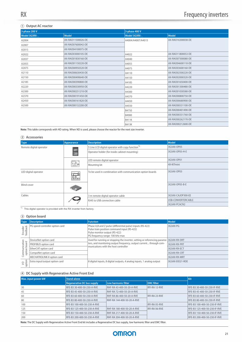
Note: This table corresponds with HD rating. When ND is used, please choose the reactor for the next size inverter.
B Accessories
C Option board
D DC Supply with Regenerative Active Front End
Note: The DC Supply with Regenerative Active Front End kit includes a Regenerative DC bus supply, low harmonic filter and EMC filter.
3-phase 200 V 3-phase 400 V
Model 3G3RX-_ Model Model 3G3RX-_ Model
A2004 AX-RAO11500026-DE A4004/A4007/A4015 AX-RAO16300038-DE
A2007 AX-RAO07600042-DE
A2015 AX-RAO04100075-DE
A2022 AX-RAO03000105-DE A4022 AX-RAO11800053-DE
A2037 AX-RAO01830160-DE A4040 AX-RAO07300080-DE
A2055 AX-RAO01150220-DE A4055 AX-RAO04600110-DE
A2075 AX-RAO00950320-DE A4075 AX-RAO03600160-DE
A2110 AX-RAO00630430-DE A4110 AX-RAO02500220-DE
A2150 AX-RAO00490640-DE A4150 AX-RAO02000320-DE
A2185 AX-RAO00390800-DE A4185 AX-RAO01650400-DE
A2220 AX-RAO00330950-DE A4220 AX-RAO01300480-DE
A2300 AX-RAO00251210-DE A4300 AX-RAO01030580-DE
A2370 AX-RAO00191450-DE A4370 AX-RAO00800750-DE
A2450 AX-RAO00161820-DE A4450 AX-RAO00680900-DE
A2500 AX-RAO00132200-DE A4550 AX-RAO00531100-DE
B4750 AX-RAO00401490-DE
B4900 AX-RAO00331760-DE
B411K AX-RAO00262170-DE
B413K AX-RAO00212600-DE
Type Appearance Description Model
Remote digital operator 5 Line LCD digital operator with copy function*1
*1 This digital operator is provided with the RX inverter from factory.
3G3AX-OP05
Operator holder (for inside cabinet mounting) 3G3AX-OP05-H-E
LED remote digital operator 3G3AX-OP01
Mounting kit 4X-KITmini
LED digital operator To be used in combination with communication option boards 3G3AX-OP03
Blind cover 3G3AX-OP05-B-E
Cables 3 m remote digital operator cable 3G3AX-CAJOP300-EE
RJ45 to USB connection cable USB-CONVERTERCABLE
3G3AX-PCACN2
Type Description Function Model
Enco
der
feed
back PG speed controller option card Phase A,B and Z pulse (differential pulse) inputs (RS-422)
Pulse train position command input (RS-422)Pulse monitor output (RS-422)PG frequency range: 100 kHz max
3G3AX-PG
Com
mun
icat
ion
optio
n bo
ard
DeviceNet option card Used for running or stopping the inverter, setting or referencing parame-ters, and monitoring output frequency, output current... through com-munications with the host controller
3G3AX-RX-DRT
PROFIBUS option card 3G3AX-RX-PRT
EtherCAT option card 3G3AX-RX-ECT
CompoNet option card 3G3AX-RX-CRT
MECHATROLINK-II option card 3G3AX-RX-MRT
I/Oop
tion Extra input/output option card 8 digital inputs, 8 digital outputs, 4 analog inputs, 1 analog output 3G3AX-EIO21-ROE
Max. input power kW Stand-alone Kit
Regenerative DC bus supply Low harmonic filter EMC filter
30 RFE-B3 30-400-50-230-A-RVE RHF-RA 43-400-50-20-A-RVE RFI-RA 12-RVE RFE-B3 30-400-50-230-IF-RVE
45 RFE-B3 45-400-50-230-A-RVE RHF-RA 72-400-50-20-A-RVE RFE-B3 45-400-50-230-IF-RVE
60 RFE-B3 60-400-50-230-A-RVE RHF-RA 86-400-50-20-A-RVE RFI-RA 23-RVE RFE-B3 60-400-50-230-IF-RVE
80 RFE-B3 80-400-50-230-A-RVE RHF-RA 144-400-50-20-A-RVE RFE-B3 80-400-50-230-IF-RVE
100 RFE-B3 100-400-50-230-A-RVE RFI-RA X5-RVE RFE-B3 100-400-50-230-IF-RVE
125 RFE-B3 125-400-50-230-A-RVE RHF-RA 180-400-50-20-A-RVE RFI-RA X6-RVE RFE-B3 125-400-50-230-IF-RVE
150 RFE-B3 150-400-50-230-A-RVE RHF-RA 217-400-50-20-A-RVE RFE-B3 150-400-50-230-IF-RVE
200 RFE-B3 200-400-50-230-A-RVE RHF-RA 304-400-50-20-A-RVE RFE-B3 200-400-50-230-IF-RVE

RX Frequency inverters
22
D Regenerative Braking unit
D Braking unit, braking resistor unit
E Computer software
Low Duty applications (50%) High Duty applications
Max. regenerative power kW Regenerative braking unit Max. regenerative power kW Regenerative braking unit
8 RLD-E0 8-400-50-0-A-RVE 7 RHD-B0 7-400-50-0-A-RVE
12 RLD-E0 12-400-50-0-A-RVE 13 RHD-B0 13-400-50-0-A-RVE
16 RLD-E0 16-400-50-0-A-RVE 18 RHD-B0 18-400-50-0-A-RVE
20 RLD-E0 20-400-50-0-A-RVE 24 RHD-B0 24-400-50-0-A-RVE
24 RLD-E0 24-400-50-0-A-RVE 30 RHD-B0 30-400-50-230-A-RVE
32 RLD-E0 32-400-50-0-A-RVE 50 RHD-B0 50-400-50-230-A-RVE
40 RLD-E0 40-400-50-0-A-RVE 70 RHD-B0 70-400-50-230-A-RVE
48 RLD-E0 48-400-50-0-A-RVE 100 RHD-B0 100-400-50-230-A-RVE
58 RLD-E0 58-400-50-0-A-RVE 125 RHD-B0 125-400-50-230-A-RVE
80 RLD-E0 80-400-50-0-A-RVE 150 RHD-B0 150-400-50-230-A-RVE
95 RLD-E0 95-400-50-0-A-RVE
116 RLD-E0 116-400-50-0-A-RVE
140 RLD-E0 140-400-50-0-A-RVE
170 RLD-E0 170-400-50-230-A-RVE
200 RLD-E0 200-400-50-230-A-RVE
Inverter Braking resistor unit
Voltage Max. motor kW Model 3G3RX-_3-phase
Braking unit AX-BCR_
Connectable min. resistance
Inverter mounted type(3%ED, 10 sec max)
Braking torque %
External resistor 10%ED, 10 sec max for built-in, 5 sec for braking unit
Braking torque %
Type AX-_ Resistance Type AX-_ Resistance
200 V(single-phase/three-phase)
0.55 A2004 Built-in 50 REM00K1200-IE 200 180 REM00K1200-IE 200 180
1.1 A2007 100 REM00K2070-IE 70 200
1.5 A2015 35 REM00K2070-IE 70 140 REM00K4075-IE 75 130
2.2 A2022 90 REM00K4035-IE 35 180
4.0 A2037 REM00K4075-IE 75 50 REM00K6035-IE 100
5.5 A2055 16 REM00K4035-IE 35 75 REM00K9020-IE 20 150
7.5 A2075 10 55 REM01K9017-IE 17 110
11.0 A2110 REM00K6035-IE 40 REM02K1017-IE 75
15.0 A2150 7.5 REM00K9017-IE 17 55 REM03K5010-IE 10 95
18.5 A2185 REM03K5010-IE 10 75 REM19K0008-IE 8 95
22.0 A2220 5 65 80
30.0 A2300 2035090-TE 4 REM19K0006-IE 6 80
37.0 A2370 60
45.0 A2450 2070130-TE 2.8 2 × REM19K0006-IE 3 105
55.0 A2550 85
400 V(three-phase)
0.55 A4004 Built-in 100 REM00K1400-IE 400 200 REM00K1400-IE 400 200
1.1 A4007 200 200
1.5 A4015 REM00K1200-IE 200 190 REM00K2200-IE 200 190
2.2 A4022 REM00K2200-IE 130 REM00K5120-IE 120 200
4.0 A4040 70 REM00K2120-IE 120 120 REM00K6100-IE 100 140
5.5 A4055 REM00K4075-IE 75 140 REM00K9070-IE 70 150
7.5 A4075 35 100 REM01K9070-IE 110
11.0 A4110 REM00K6100-IE 100 50 REM02K1070-IE 75
15.0 A4150 24 REM00K9070-IE 70 55 REM03K5035-IE 35 110
18.5 A4185 REM03K5035-IE 35 90 REM19K0030-IE 30 100
22.0 A4220 20 75 85
30.0 A4300 4015045-TE 16 REM19K0020-IE 20 95
37.0 A4370 4017068-TE 11 REM38K0012-IE 15 125
45.0 A4450 100
55.0 A4550 4035090-TE 8.5 2 × REM19K0020-IE 10 100
75.0 B4750 3 × REM19K0030-IE 75
90.0 B4900 4070130-TE 5.5 2 × REM38K0012-IE 6 105
110.0 B411K 4090240-TE 3.2 3 × REM38K0012-IE 4 125
132.0 B413K 105
Type Description Model
Computer software Configuration and monitoring software tool CX-Drive
CX-One
Software tool for energy saving calculation €Saver
In the interest of product improvement, specifications are subject to change without notice.
ALL DIMENSIONS SHOWN ARE IN MILLIMETERS.
To convert millimeters into inches, multiply by 0.03937. To convert grams into ounces, multiply by 0.03527.
Cat. No. I116E-EN-06A