Embed Size (px)
Citation preview

Engineering Review, Vol. 36, Issue 2, 123-131, 2016. 123 ______________________________________________________________________________________________________________________
RVM - BASED ADABOOST SCHEME FOR STATOR INTERTURN
FAULTS OF THE INDUCTION MOTOR
Weiguo Zhao1 – Kui Li1 – Shaopu Yang2 – Liying Wang3*
1School of Electrical Engineering, Hebei University of Technology, Tianjin 300130, China 2School of Mechanical Engineering, Shijiazhuang Railway University, Shijiazhuang 050043, China 3School of Water Conservancy and Hydropower, Hebei University of Engineering, Handan 056038, China
ARTICLE INFO Abstract:
Article history:
Received: 9.11.2014.
Received in revised form: 4.5.2015.
Accepted: 7.5.2015.
This paper presents an AdaBoost method based on
RVM (Relevance Vector Machine) to detect and
locate an interturn short circuit fault in the stator
windings of IM (Induction Machine). This method
is achieved through constructing an Adaboost
combined with a weak RVM multiclassifier based
on a binary tree, and the fault features are
extracted from the three phase shifts between the
line current and the phase voltage of IM by
establishing a global stator faulty model. The
simulation results show that, compared with other
competitors, the proposed method has a higher
precision and a stronger generalization capability,
and it can accurately detect and locate an interturn
short circuit fault, thus demonstrating the
effectiveness of the proposed method.
Keywords:
Relevance vector machine
AdaBoost
Stator interturn faults
Induction motor
*Corresponding author.
E-mail address: [email protected]
1 Introduction
Nowadays induction motors are widely used in
many industrial processes owing to their high
reliability, simple construction and robust design,
but undoubtedly they are always exposed to a
variety of complex environments and conditions
which are accompanied with the natural aging
process of any machine, thus causing various motor
failures [1, 2]; as a result, their maintenance and
fault detection become more and more important.
Fault detection of IM has now received extensive
attentions since according to some studies [3, 4, 5],
in recent years, stator faults have been responsible
for 37% of the IM failures [6, 7]. The most frequent
IM failures are stator winding faults, resulting from
the phase to phase, turn to turn, or winding to earth
short circuit. For better detection of an interturn
short circuit fault in the stator windings, modelling
of IM with shorted turns is the first step in
constructing turn fault detection systems. It follows
that the simulated models of transient and steady
state behavior of IM enable correct evaluation of the
measured data by diagnostics techniques [8], and
thus many models have been successfully used to
study the transient and steady state behavior of IM
with short circuited turns.
For the location and detection of an interturn short
circuit fault, its essence is pattern recognition, and
the different phase faults are treated as labels of a
classifier. Many approaches based on pattern
recognition for interturn short circuit fault such as
ANN (Artificial Neural Networks) [9], SVM
(Support Vector Machine) have been recently used.
Given the fact that it is very hard to obtain good
generalization results when the training samples are

124 W. Zhao et al.: RVM - based AdaBoost scheme for stator… ______________________________________________________________________________________________________________________
insufficient, and that they can be also easily trapped
in a local optimum [10], the ANN approach based
on the statistical characteristics of large-scale
samples is used; by contrast, SVM as a machine
learning method based on statistical learning theory,
exhibits excellent performances in dealing with the
classification questions. However, it entails some
significant shortcomings, i.e., it is affected by the
difficulty of appropriately selecting its parameters,
so data and computation used to determine them
have no result, its output is a point estimate rather
than a conditional distribution, moreover, it does
not allow for the free use of an arbitrary kernel
function owing to the rule of Mercer’s condition
[11].
RVM [12] is a probabilistic sparse kernel model
identical in functional form to SVM, where a
Bayesian approach to learning is adopted through
introducing a prior over the weights governed by a
set of hyperparameters. RVM can obtain a
generalization performance comparable to SVM by
using dramatically fewer training samples.
Furthermore, it suffers from none of the other
limitations of SVM outlined above, and it is good
classification ability with great sparsity/ efficiency.
AdaBoost [13, 14] is the latest data mining method
for increasing the learning ability of a prediction
system, and it can be used in conjunction with many
other types of learning algorithms. In this way, it
can not only increase the classification accuracy in
any given weak classifier but also improve the
generalization ability in strong classifiers.
In this paper, the AdaBoost algorithm incorporated
with the RVM multiclass classifier based on a
binary tree is used to detect and locate an interturn
short circuit fault in the stator windings of IM.
Meanwhile, the fault features are extracted from the
three phase shifts between the line current and the
phase voltage of the IM by establishing a global
stator faulty model. The simulation results illustrate
accordingly that the proposed approach is very
effective.
2 AdaBoost algorithm
Pattern classification is a typical application of
AdaBoost algorithm. For binary classification, its
main idea is that a set of weight distribution should
be maintained for a set of training samples. In each
iteration, the AdaBoost calls a given weak learning
algorithm. The weights which correspond to the
wrong samples will be increased so that weak
learning is forced to be focused on the hard-to-
classify samples of the training set, and the task of
the weak learner is to find the right weak estimate
based on weight distribution of the samples. The k-
class classification is one of the extensions of
binary classification, now AdaBoost.M1 algorithm
is given to solve k-class problem as follows:
1. Input: a set of training samples with labels
<(x1,y1),…,(xN,yN)>, the number of cycles T.
2. Initialize: the weights of training samples:
Wi1= D(i) =1/N, for all i=1,2,…,N.
3. Do for t=1, 2,…,T:
(a)
N
ti
t
t
W
WP
1
;
(b) Pass Pt on to the Component Learner, and return
estimate ht: X→Y;
(c) Calculate the training error of ht:
iit
Nt
it yxhP 1
;
(d) Set ttt 1 ;
(e) Update the weights of training samples:
iit yxh
tt
it
i WW
11 ;
4. Output:
iittf yxhYy
xh
/1logmax
arg ,
where
else
trueisif
,0
,1 .
3 RVM for classification
Tipping [12] proposed RVM (Relevance Vector
Machine) to recast the main ideas behind SVM in a
Bayesian context. For two classes classification,

Engineering Review, Vol. 36, Issue 2, 123-131, 2016. 125 ______________________________________________________________________________________________________________________
given a training dataset {xn, tn}N n=1, and the
corresponding output is tn ∈{0,1}, the following
classification model can be used to describe the
mapping relation between the input pattern vector x
and the output t:
ytwxyt nnn ,, (1)
Where the errors ε = (ε1… εn) are modeled
probabilistically as an independent zero-mean
Gaussian process, with the variance σ2, so
N
n nNp1
2,0| , w = (w1… wM) is the
parameter vector and y (xn, w) can be expressed as a
linearly weighted sum of some basis functions φ (x):
wywxwwxyM
mmm
,, 01
(2)
Here Φ = [φ1, L, φM] is the N × M design matrix
whose columns comprise the complete set of M
basis vectors. Note that the form of the function (4)
is equal to the form of the function for a SVM
where we identify our general basis functions with
the kernel as parameterized with the training
vectors, mm xxKx , and
nNnn xxKxxKx ,,...,,1 when y(x|w) is
classified, the Sigmoid function is used as:
wxyii
iewxywtp
;1
1;|1
(3)
Then the Likelihood function is obtained as:
N
i
ti
ti
ii wxywxywtp1
1;1;| (4)
Using the Laplace approximation, and for a fixed
value of α, the mode of the posterior distribution
over w is obtained by maximizing:
atpwtpw
wMP ||logmax
arg (5)
Its Logarithmic likelihood function is:
N
I
Tiiii Awwytyt
atpwtp
1
5,01log1log
||log
(6)
The mode and variance of the Laplace
approximation for w are:
12 T
MP
MPT
MP
A
Btw
(7)
Where B is N×N diagonal matrix with
bnn=f(xn;w)(1-f(xn;w)), the marginal likelihood is:
2/12/
2|,|
|,|,|
MP
MMPMP awpwxtp
dwawpwxtpaxtp
(8)
When maximizing the above equation with respect
to each αi, one eventually obtains:
N
iiii
new
MPT
i
inewi
N
t
Bt
0,
2
2
2
(9)
One gives first guess value of a, then renews
unceasingly through the above step to approach
wMP; once the iteration procedure has converged to
the most probable values, the majority of ai will be
0, other ai are close to infinity and their
corresponding xi are relevant vectors.
4 The stator faulty model and the faulty
features
4.1 Global stator faulty model
To obtain the healthy and faults of a three phase
induction motor, we use the global stator faulty
model proposed in [15, 16], which is described in
Fig. 1. It can be seen that the model includes the
common and differential parts, the first one
corresponds to the dynamic model in healthy
operation, and the second one corresponds to the
dynamic model in faulty operations.
Fig. 2 shows a three phase two-pole induction motor
with a short-circuit winding at phase B, this fault
induces in the stator new windings Bcc short circuit

126 W. Zhao et al.: RVM - based AdaBoost scheme for stator… ______________________________________________________________________________________________________________________
and is localized according to first phase by the angle
θcc=2π/3.
Figure 1. Global stator faulty model.
Two parameters are introduced in the differential
part through defining the faults in the stator as
follows [16]:
Interturn short circuit at
phase b First pole of phase a
a
c
b
Second pole of phase a
Short circuit winding
θcc
Bcc
Figure 2. Short circuit winding representation.
The location parameter, θcc, is the angle between the
inter turn short circuit stator winding and the first
stator phase axis, which can take only one of three
values 0,2π/3 and 4π/3 and which corresponds to
the short circuit on the phases A, B and C,
respectively. The detection parameter, μcc is the
ratio between the number of interturn short-circuit
windings and the total number of turns in the
healthy phase used to quantify the unbalance:
s
cc
ccn
nk
k (10)
Here ncck is the number of shorted turns and ns is the
number of turns at each phase. The short-circuit
currents in the differential part can be described
below:
dqccs
cc
cc UPQPR
ik
k
k
3
2 (11)
The state space representation of the stator faulty
model is given by:
tUDtCxtY
tBUtXAtX
kk cccc
, (12)
Tqdqd iiX ,,, (13)
Tqd UUU , (14)
Tqd iiY , (15)
2212
2111
AA
AAA (16)
f
rs
f
rs
L
RR
L
RR
A
11 (17)
mf
r
f
fmf
r
LL
R
L
LLL
R
A
12 (18)
r
r
R
RA
0
021 (19)
m
r
m
r
L
R
L
R
A
0
0
22 (20)
T
f
f
L
LB
000/1
000/1 (21)

Engineering Review, Vol. 36, Issue 2, 123-131, 2016. 127 ______________________________________________________________________________________________________________________
0001
0001C (22)
m
le TT
(23)
3
1 3
2,
kcc
s
cc
cccc PQPR
Dk
k
kk
(24)
2
2
sincossin
cossincos
kkk
kkk
k
cccccc
cccccc
ccQ
(25)
3/2sinsin
3/2coscos
P (26)
Where Te and Ti are the electromagnetic and the
load torques respectively, τm is the mechanical time
constant, id and iq are the dq stator current
components respectively, φd and φq are dq rotor flux
linkage components, Ud and Uq are the dq stator
voltage components, θ is the electrical angle, and
dtd / is the electrical angular velocity, Rs and
Rr are the stator and the rotor resistances, Lf and Lm
are the leakage inductances referring to the stator
and the magnetizing inductance, respectively.
4.2 Determination of faulty features
The determination of faulty features is a key step in
any monitoring and fault diagnosis systems which
directly affect the diagnosis accuracy of the
systems. For the induction motor with stator
interturn faults under normal operation and
unbalanced conditions, phase voltages and line
currents are the same in magnitude but shifted by
2π/3 electric angle. However, under faulty
operation, not only the phase currents are unequal
but also the phase shifts.
When the number of short circuit interturn and the
load torque changes the induction motor parameters
such as the global leakage inductance Lf, the stator
resistance Rs and the magnetizing inductance Lm
change, respectively, thus each phase shift can be
expressed by the following equation[17]:
s
s
X
Rarctan (27)
Here, Rs and Xs are the stator resistance and the
stator reactance, respectively. Fig. 3-5 show the
three phase shifts under different shorted turns and
under a load torque of 3Nm for fault on phase A, B
and C, respectively. Consequently, it can be seen
that, for fault on phase A, B and C, each phase shift
is also different, moreover, with an increase in
shorted turns, this difference becomes obvious, thus
performing the sensitivity of the phase shifts for the
interturn shorted circuit fault. The phase shift is
therefore an idea feature, i.e., an indictor of the
location for stator shorted circuit fault.
0 5 10 15 20 25
40
42
44
46
48
50
52
54
56
58
60
62
Faulty turns
Ph
ase
sh
ift
/°
Phase A
Phase B
Phase C
Figure 3. Each phase shift for fault on phase A.
0 5 10 15 20 25
40
42
44
46
48
50
52
54
56
58
60
62
Faulty turns
Ph
ase
sh
ift
/°
Phase A
Phase B
Phase C
Figure 4. Each phase shift for fault on phase B.
0 5 10 15 20 25
40
42
44
46
48
50
52
54
56
58
60
62
Faulty turns
Ph
ase
sh
ift
/°
Phase A
Phase B
Phase C
Figure 5. Each phase shift for fault on phase C.
For RVM, the choice of kernel is important to its
performance when there is no prior knowledge in

128 W. Zhao et al.: RVM - based AdaBoost scheme for stator… ______________________________________________________________________________________________________________________
the learning process and when the Gaussian kernel
function outperforms the other. The Gaussian kernel
function is given as:
2
2
2exp,
yxyxK (28)
Here σ is a width factor which shapes the width of
the Gaussian kernel function, the performance of
RVM classifier depends mainly on the selection of
σ.
As there are four different conditions including one
normal and three faulty ones for the stator, this
binary classifier needs to be popularized into a
multiclass classifier. The method based on binary
tree is used for dividing all conditions into two
subclasses, then further ones into two secondary
subclasses. Being processed as such until all the
nodes contain single conditions, the nodes are the
leaves of a decision tree. So by this method, the
multiclass classification problem is decomposed
into multiple binary classification problems
corresponding to k-1 RVM classifiers; Fig. 6
illustrates the weak RVM multiclass classifier based
on binary tree.
RVM1
Fault
featureRVM2 RVM3
NormalFault on
phase A
Fault on
phase B
Fault on
phase C
Figure 6. Weak RVM multiclass classifier based on
binary tree.
In this work, the RVM multiclass classifier based
on binary tree is used as a classifier of Adaboost,
and its kernel parameter σ is set to be relatively
large and same/equal in the three weak classifiers.
The adequate decreasing step length σstep is set to be
the kernel parameter σ of each RVM classifier and
the same σ can be used many times for each
iteration of each classifier as long as the
classification error of the multiclass classifier is less
than 0.5. These weight training samples are adjusted
according to the classification error until the kernel
parameter σ of each binary classifier achieves the
threshold σmin or until the training error is satisfied.
The process of AdaBoost-RVM multiclassifier is
described as follows:
1. Input: a set of training samples with labels
<(x1,y1),…,(xN,yN)>, the number of cycles T.
2. Initialize: the weights of training samples:
Wi1= D(i) =1/N, for all i=1,2,…,N. The minimum
of σ is σini,the step size of σ is σstep, the threshold
is σmin.
3. Do for t=1, 2,…,T:
(a)
N
ti
t
t
W
WP
1
;
(b) Train RVM multiclass classifier ht and pass Pt
on to it, then return estimate: ht: X→Y;
(c) Calculate the training error of ht:
iit
Nt
it yxhP 1
;
(d) If εt > 0,5 and
min3,21,max RVMRVMRVM , then
stepRVMRVMRVM
RVMRVMRVM
3,21
3,21
,max
,max
and return to (b), or continue
(e) Set ttt 1 ;
(f) Update the weights of training samples:
iit yxh
tt
it
i WW
11 ;
4. Output:
iittf yxhYy
xh
/1logmax
arg ,
where
else
trueisif
,0
,1 .
Engineering Review, Vol. 36, Issue 2, 123-131, 2016. 129 ______________________________________________________________________________________________________________________
5 Simulation results and analysis
To evaluate the proposed method of the location of
stator interturn faults in IM in this paper, the
simulation data are required. For this purpose, a
range sample sets are acquired through the global
stator faulty model, which contains different
conditions under different shorted turn faults. All
samples are under three different load conditions,
and each load condition contains the normal faults
and faults ranging from 1 to 15 shorted turns, thus a
total of 138(3+15×3×3) samples constitute a sample
set. In this way, 2/3 of them present the training
samples, the rest are used as test samples to test the
performance of the method of faults location. Fig. 7
shows the acquired samples set, the parameters of
AdaBoost-RVM are set as follows: σini=3, σmin=0.1
and T=100.
3 48 93 138
40
60
Phase A
Normal Fault on phase A Fault on phase B Fault on phase C
3 48 93 138
40
60
Phase B
3 48 93 138
40
60
Phase C
Samples
Figure 7. Samples set.
In order to observe the influence of the step length
σstep on the AdaBoost-RVM, σstep is taken as 0.1, 0.2
and 0.3 to training. Fig. 8 illustrates the influence of
different σstep on AdaBoost-RVM. It can be found
that the change of σstep is less sensitive to the final
result. With an increase of the iterative times, the
number of the combined RVM multiclass classifier
is also increased. At the early period of the iteration,
the decrease of σ does not much contribute to the
training accuracy, while with an increase in
iteration, the accuracy begins to rise rapidly until
the σ of three binary RVM classifiers has been
reduced to a certain degree. From the convergence
speed, the multiclass RVM classifier with the value
σstep=0.1 is the fastest, but, although the
convergence processes of model training are
different, the final training accuracy is stable.
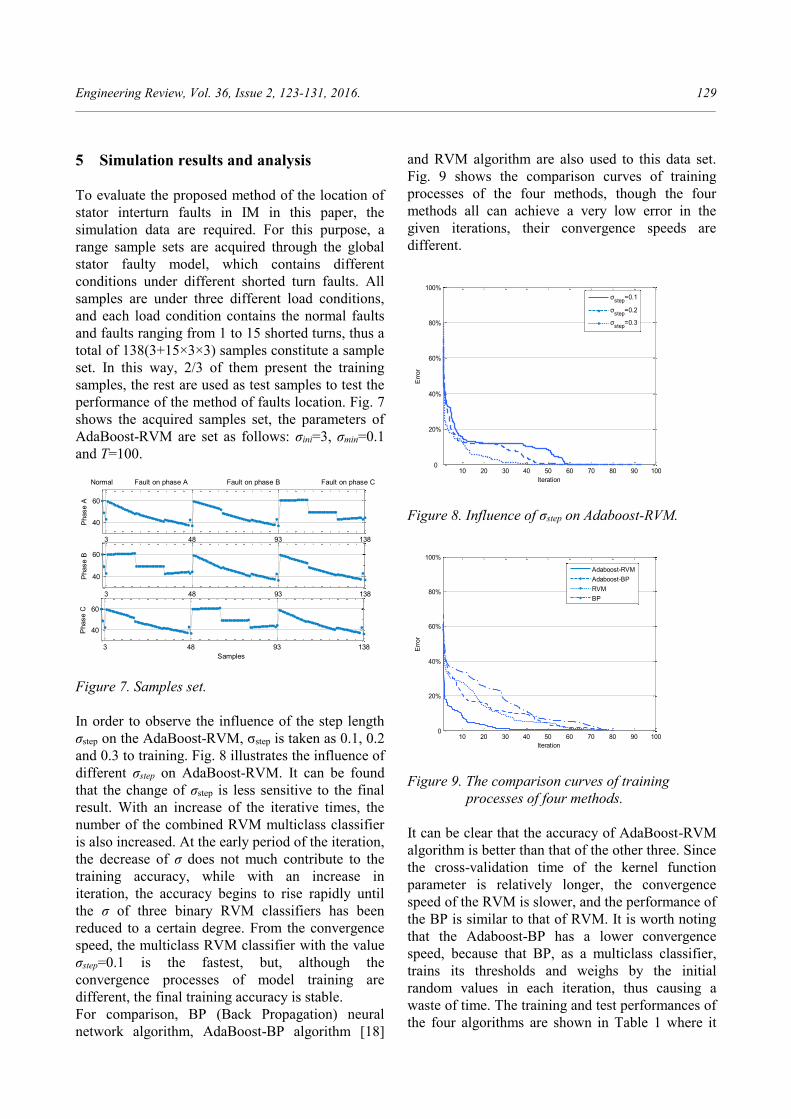
For comparison, BP (Back Propagation) neural
network algorithm, AdaBoost-BP algorithm [18]
and RVM algorithm are also used to this data set.
Fig. 9 shows the comparison curves of training
processes of the four methods, though the four
methods all can achieve a very low error in the
given iterations, their convergence speeds are
different.
10 20 30 40 50 60 70 80 90 1000
20%
40%
60%
80%
100%
Iteration
Err
or
σstep
=0.1
σstep
=0.2
σstep
=0.3
Figure 8. Influence of σstep on Adaboost-RVM.
10 20 30 40 50 60 70 80 90 1000
20%
40%
60%
80%
100%
Iteration
Err
or
Adaboost-RVM
Adaboost-BP
RVM
BP
Figure 9. The comparison curves of training
processes of four methods.
It can be clear that the accuracy of AdaBoost-RVM
algorithm is better than that of the other three. Since
the cross-validation time of the kernel function
parameter is relatively longer, the convergence
speed of the RVM is slower, and the performance of
the BP is similar to that of RVM. It is worth noting
that the Adaboost-BP has a lower convergence
speed, because that BP, as a multiclass classifier,
trains its thresholds and weighs by the initial
random values in each iteration, thus causing a
waste of time. The training and test performances of
the four algorithms are shown in Table 1 where it

130 W. Zhao et al.: RVM - based AdaBoost scheme for stator… ______________________________________________________________________________________________________________________
can be seen that the BP classifier and the RVM
classifier have a similar performance, the
AdaBoost-BP comes second, and the AdaBoost-
RVM is the best.
For the AdaBoost-RVM, three RVM kernel
function parameters σ in weak classifier alternately
diminish so that the precision gained each time is
appropriate. It makes distribution weight not too
great for some hard-to-classify samples, thus
effectively controlling samples frequency obtained
by re-sampling and avoiding weight expansion
problem [19]. After 100 iterations, the obtained
repeated sampling frequency is shown in Figure 10
from which it can be seen that the repeated rate of
some samples selected, named key learning
samples, is higher than the repeated rate of other
samples named rich information samples. The case
in which some samples have too high frequencies
does not appear due to the appropriate control of the
weight value.
Table 1. The performance of four methods
Algorithm
Training
accuracy
(Error
number)
Training
time
Test
accuracy
(Error
number)
AdaBoost-
RVM
100%
(0) 27.8s
97.63%
(1)
AdaBoost-
BP
100%
(0) 36.5s
95.65%
(2)
RVM 98.91%
(1) 21.7s
91.30%
(4)
BP 98.91%
(1) 29.2s
93.48%
(3)
1 10 20 30 40 50 60 70 80 920
10
20
30
40
50
60
Samples
Sam
plin
g f
requency
Figure 10. The frequency distribution of training
samples.
6 Conclusions
An effective method for detecting and locating an
interturn short circuit on the stator windings of IM
is proposed. This diagnosis method establishes the
AdaBoost algorithm combined with weak RVM
multiclassifier based on a binary tree, and the three
phase shifts between the line current and the phase
voltage of IM are hence used as fault features. The
modeling idea of this method is clear and easy to
operate. The simulation results demonstrate that the
proposed method has higher diagnosis accuracy and
a better generalization capability than its
counterparts.
Acknowledgments
This work - Basic Research into Scientific
Instruments is supported by the Special Fund of the
National Natural Science Foundation of China No.
11227201, the National Natural Science Foundation
of China No.11202062, and the Natural Science
Foundation of Hebei Province of China No.
E2010001026.
References
[1] Karami, F., Poshtan, J., Poshtan, M.: Detection
of broken rotor bars in induction motors using
nonlinear Kalman filters, ISA Transactions, 49
(2010), 189-195.
2 Siddique, A., Yadava, G. S., Singh, B.: A
review of stator fault monitoring techniques of
induction motors, IEEE Transactions on
Energy Conversion, 20 (2005), 106-114.
3 Cusido, J., Romeral, L., Ortega, J. A.: Fault
detection in induction machines using J.A.
power spectral density in wavelet
decomposition, IEEE Transactions on
Industrial Electronics, 55 (2008), 633-643.
4 Kowalski, C.T., Orlowska-Kowalska, T.:
Application of Neural Networks for the
Induction Motor Faults Detection,
Mathematics and Computers in Simulation, 63
(2003), 435-448.
[5] Bacha, K., Salem Ben, S., Chaari, A.: An
improved combination of Hilbert and Park
transforms for fault detection and
identification in three-phase induction motors,
International Journal of Electrical Power &
Energy Systems, 43 (2012), 1006-1016.

Engineering Review, Vol. 36, Issue 2, 123-131, 2016. 131 ______________________________________________________________________________________________________________________
[6] Filippetti, F.: State of art of model diagnostic
procedures for induction machines inter-turns
short circuits, Proc. IEEE SDEMPED, Gijon,
Spain, Sep. 1999, 19–31.
[7] Siddique, A., Yadava, G.S.: A review of stator
fault monitoring techniques of induction
motors, IEEE Transactions on Energy
Conversion, 20 (2005) 106-114.
[8] Arkana, M., Kostic-Perovic, D., Unsworth, P.
J.: Modelling and simulation of induction
motors with inter-turn faults for diagnostics,
Electric Power Systems Research, 75 (2005),
57–66.
[9] Mirceska, A., Kulakov, A., Stoleski, S.: The
Role of Artificial Neural Networks in Detection
of Pulmonary Functional Abnormalities,
Engineering Review, 29 (2009), 1-11.
[10] Kim, K.J., Han, I.: Genetic algorithms
approach to feature discretization in artificial
neural networks for the prediction of stock
price index. Expert Systems with Application,
19 (2008), 125–132.
[11] Hernández, N., Talavera, I., Biscay, R. J.,
Ferreira, M. M. C., Porro Muñoz, D.:
Relevance vector machines for multivariate
calibration purposes, Chemometrics, 22
(2008), 386-694.
[12] Tipping, M. E.: The relevance vector machine,
Advances in Information Processing System, 2
(2000), 652-658.
[13] Schapire, R. E., Singer, Y., Bartlett, P., Lee
W.: Boosting the margin: a new explanation
for the effectiveness of voting methods, The
Annals of Statistics, 26 (1998), 1651–1686.
[14] Dietterich, T.G.: An experimental comparison
of three methods for constructing ensembles of
decision trees: bagging, boosting, and
randomization, Machine Learning, 40 (2000),
139-157.
[15] Bouzid, M., Champenois, G., Bellaaj, N. M.,
Signac, L., Jelassi, K.: An Effective Neural
Approach for the Automatic Location of Stator
Interturn Faults in Induction Motor, IEEE
Transactions on Industrial Electronics, 55
(2008), 4277-4289.
[16] Bachir, S. S., Tnani, J. C., Trigeassou, G.:
Champenois Diagnosis by parameter
estimation of stator and rotor faults occurring
in induction machines, Industrial Electronics,
IEEE Transactions on Industrial Electronics,
53 (2006), 963 – 973.
[17] Dash R.N., Subudhi B., Das S.: A comparison
between MLP NN and RBF NN techniques for
the detection of stator inter-turn fault of an
induction motor, International Conference on
Industrial Electronics, Control and Robotics,
Rourkela, India, 2010, 251-256.
[18] Li X., Wang L., Eric S.: AdaBoost with SVM-
based component classifiers, Engineering
Applications of Artificial Intelligence, 21
(2008), 785-795.
[19] Ratsch, G., Onoda, T., Muller, K. R.: Soft
Margins for Adaboost, Machine Learning, 42
(2001), 287-290.