Embed Size (px)
Citation preview
ATD2_1030_v1_RTC_Observer_UM last updated 15 Sep 2017 page 1 of 50
1
Ramp Traffic Console (RTC) 2
Ramp Manager Traffic Console (RMTC) 3
Observer Mode 4
User Manual 5
ATD-2 Team 6 7
Abstract 8
This document serves as a user manual for the Observer Mode Ramp Traffic Console 9
(RTC) in Charlotte Douglas International Airport Ramp Control Tower. It describes the 10
elements of the full RTC interface and provides explanations for how to interact with the 11
RTC while managing ramp traffic using one of the four RTC sector displays. The RTC 12
provides digitally updated data for all flights including Earliest Off Block Times (EOBT) 13
and Traffic Management Initiatives. Use of the RTC in observer mode allows only for 14
observer and reading of data provided on RTC. In Observer Mode, the RTC may not be 15
used to make data entries. This includes pushback, holds, and proceed inputs as well as 16
updates to a flights data using the flight menu. However, using the RTC in Observer Mode 17
allows for real time observation of ramp operations including pushback and hold entries 18
made by the ramp sector controllers. The pushback advisories and Traffic Management 19
Initiative information is also provided in Observer Mode. The RTC also provides 20
notifications, runway departure counts and lists and near arrival flight lists as additional 21
sources of information for management of ramp traffic. There are also detailed instructions 22
for how to manage traffic with Surface Time Based Metering (STBM) advisories provided 23
on RTC if in STBM mode. This document also provides instructions for use of the Ramp 24
Manager Traffic Console (RMTC) while performing ramp manager functions such as 25
managing the priority flight list, setting ramp status, and setting the metering mode. The 26
RTC and RMTC ramp tool are one component of a suite of ATD-2 Tools. 27 28
ATD2_1030_v1_RTC_Observer_UM last updated 15 Sep 2017 page 2 of 50
Contents 29
Contents ............................................................................................................................. 2 30
1 Getting Started .......................................................................................................... 4 31
2 General Description of the RTC Interface ............................................................. 5 32
3 RTC Display Overview and Sector Map Settings .................................................. 6 33
3.1 Set and Save User Profile ................................................................................. 6 34
3.2 Notifications and Notifications Panel .............................................................. 7 35
3.3 Map Options ...................................................................................................... 8 36 3.3.1 Pushback Time ................................................................................................ 9 37
3.3.2 Gate Conflict Settings ................................................................................... 10 38
3.3.3 Bloom Icon Upon Hover-Map Option .......................................................... 11 39
3.3.4 Show Near Arrival Count-Map Option......................................................... 11 40
3.3.5 Reset Strip Font............................................................................................. 12 41
3.3.6 Set Views, Zoom and Rotate Map ................................................................ 12 42
3.4 Search ............................................................................................................... 13 43
3.5 Runway Utilization, Ramp Status, and Metering Mode ............................. 14 44 3.5.1 Runway Utilization ....................................................................................... 14 45
3.5.2 Ramp Status .................................................................................................. 14 46
3.5.3 Metering Mode.............................................................................................. 15 47
3.6 Departure and Arrival Count Boxes and Lists ............................................ 16 48
3.7 Long On Board (Lengthy Taxi Delay) .......................................................... 17 49
4 Flight Strips and Icons............................................................................................ 17 50
4.1 Flight Entries and Right Click Menu: Updating flight state ...................... 18 51 4.1.1 Departures and Arrivals, Colors, Flight States, Solid and Hollow icons ...... 18 52
4.1.2 Display of TMIs and Airspace Constraint Information on Flights ............... 21 53
5 Flight Menu ............................................................................................................. 25 54
5.1 How to Update Surface Status using the Flight Menu ................................ 26 55 5.1.1 Departure Details .......................................................................................... 30 56
5.1.2 Metering Status, Flight Status and Operational Status ................................. 30 57
5.1.3 Scratch Pad entry, Return to Gate, and Remove Icon................................... 32 58
6 Metering Modes ...................................................................................................... 32 59
6.1 Surface Time Based Metering (STBM)......................................................... 33 60 6.1.1 Exempt flights ............................................................................................... 34 61
6.1.2 Priority Flights .............................................................................................. 34 62
6.1.3 TMI Flights ................................................................................................... 34 63
6.1.4 EOBTs and Gate Hold Time Advisories ...................................................... 35 64
6.1.5 ‘Planning’ Group .......................................................................................... 35 65
6.1.6 “Ready” Group.............................................................................................. 36 66
6.1.7 ‘Uncertain’ group .......................................................................................... 39 67
6.1.8 ‘Out’, ‘Taxi’ and ‘Queue’ Groups ................................................................ 40 68
7 RMTC ...................................................................................................................... 42 69
7.1 RMTC Tools Menu: Metering Modes........................................................... 42 70 7.1.1 No Metering .................................................................................................. 42 71

ATD2_1030_v1_RTC_Observer_UM last updated 15 Sep 2017 page 3 of 50
7.2 Departure Sequence Metering ....................................................................... 43 72
7.3 Surface Time Based Metering (STBM)......................................................... 44 73
7.4 RMTC Tools Menu: Ramp Status ................................................................ 45 74
7.5 RMTC Tools Menu: Priority Flights List ..................................................... 47 75
Appendix A: Acronyms .................................................................................................. 50 76 77
78
79
ATD2_1030_v1_RTC_Observer_UM last updated 15 Sep 2017 page 4 of 50
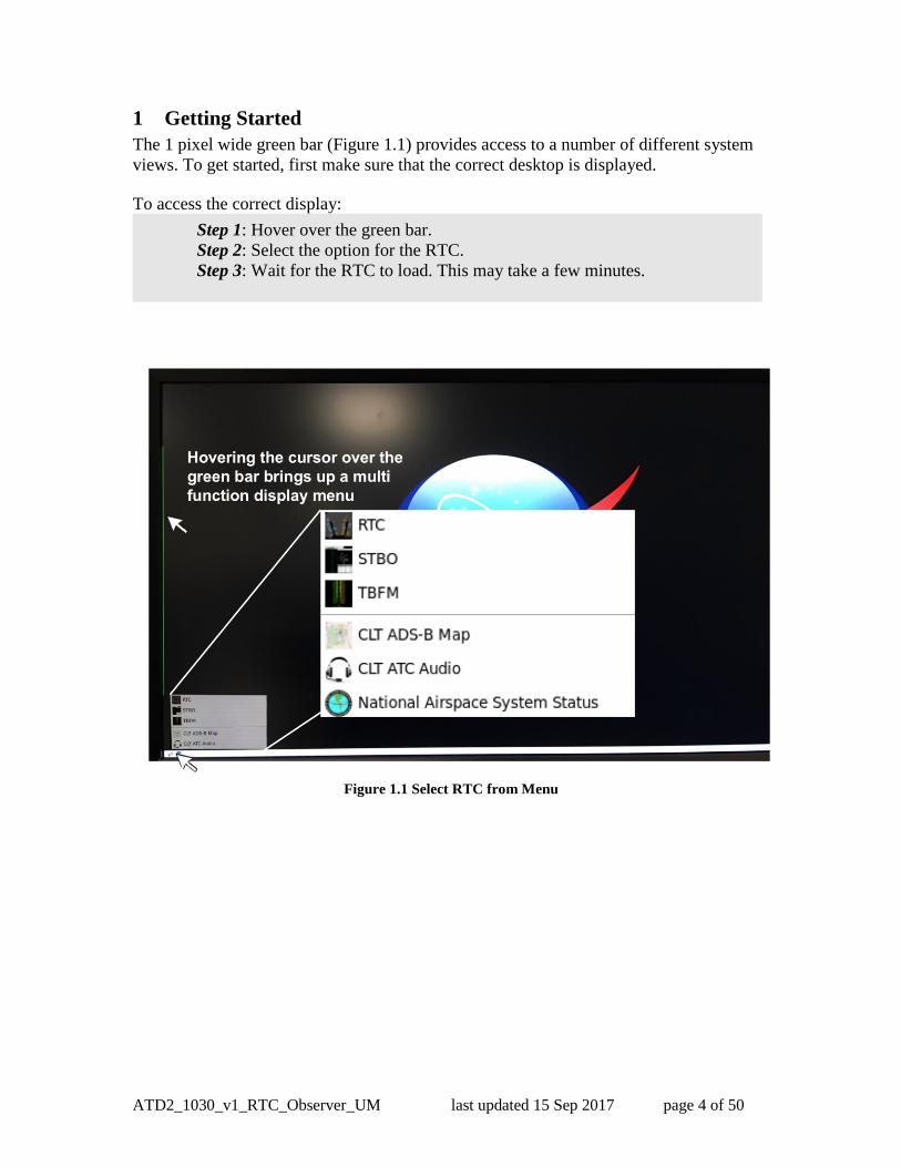
1 Getting Started 80
The 1 pixel wide green bar (Figure 1.1) provides access to a number of different system 81
views. To get started, first make sure that the correct desktop is displayed. 82 83
To access the correct display: 84
85 86
87 88
Figure 1.1 Select RTC from Menu
89
Step 1: Hover over the green bar.
Step 2: Select the option for the RTC.
Step 3: Wait for the RTC to load. This may take a few minutes.

ATD2_1030_v1_RTC_Observer_UM last updated 15 Sep 2017 page 5 of 50
2 General Description of the RTC Interface 90
The Ramp Traffic Console (Figure 2.1), is comprised of an interactive map display and 91
“electronic flight strip” and flight icons that reflect user inputs and flight state 92
information. 93
94
95 Figure 2.1. RTC Interactive Map Display. 96
97
It is possible to save and load display configurations, and search for flights. Also 98
provided are notifications and, if applicable, Traffic Management Initiative (TMI) and 99
gate conflict information for each flight. 100
The RTC map displays surveillance data and provides a visual representation of current 101
aircraft state and position in the ramp, the Airport Movement Area (AMA), and near 102
airspace. When a flight loses surveillance data, the flight becomes a hollow icon that may 103
be repositioned on the map using drag and drop. There are many data exchange elements 104
shared between Ramp (RTC/RMTC) and ATC (STBO Client) including TMI 105
information, notifications, ramp status, runway utilization and closure information. The 106
RTC is also able to support all three metering modes: No Metering, Departure 107
Sequencing and Surface Time Based Metering (STBM). If in Departure Sequencing 108
mode, there are departure lists and hold lists available to support Departure Sequencing. 109
If STBM is in effect, then the RTC will provide metering advisories for certain flights in 110
the form of recommended gate hold times. 111

ATD2_1030_v1_RTC_Observer_UM last updated 15 Sep 2017 page 6 of 50
3 RTC Display Overview and Sector Map Settings 112
The RTC map view is adjustable by using the mouse to click, drag and drop the map and 113
by using the scroll wheel to adjust the zoom level. 114
3.1 Set and Save User Profile 115
There are four default RTC sector map displays available, preconfigured to display each 116
of the four ramp sectors. These include North, East, South and West sectors. Once 117
opened, the default sector view may be configured based on user preference. 118
119
To choose a RTC sector view select the User Profile tab located on top left status bar. 120
Choose Load to select the desired profile from the list of already saved profiles, for 121
example choose “RampSouth.xml” to open the South Sector RTC display. 122
123
To choose a RTC sector view: 124
125
126
127 Figure 3.1. Load User Profile. 128
Step 1: Click on User Profile as shown in Figure 3.1 below.
Step 2: Choose Load to open menu of available profiles.
Step 3: Select a user profile from list of options.
Step 4: Click “Open”.

ATD2_1030_v1_RTC_Observer_UM last updated 15 Sep 2017 page 7 of 50
To save your settings as a unique profile name: 129
130
131
Figure 3.2. Save User Profile. 132
Choose the Save option to save your settings as a unique profile name, for example, 133
“JohnDoe_RampSouth123”. The saved user profile will then be available to “Load” from 134
the User Profile Options. 135
3.2 Notifications and Notifications Panel 136
The RTC provides notifications in the form of a Notification icon, Notification banner, 137
and a Notification window (Figure 3.3). These notifications are generated when new 138
information is populated in the system. This new information may originate from the 139
STBO Client or from an outside source, such as SWIM, OIS, NTML, or other ATD-2 140
users. Notifications are always related to events that impact multiple flights or the airport 141
(e.g., Ground Stops, runway closures, metering events), and are never issued for single 142
flights. For events or restrictions related to a single flight, the flight’s datablock, 143
properties, and/or entry in the Flights Table are modified in some way that’s more salient 144
then the standard display of information (without events or restrictions). 145
When new notifications are received, the Notification icon is yellow and displays the 146
number of new notifications (Figure 3.3). The Notification banner will display the subject 147
of the notification and the time range of the event. New notifications are highlighted in 148
yellow in the Notification window. When notifications are acknowledged, the 149
Step 1: Click on User Profile as shown in Figure 3.2 below.
Step 2: Choose Save to open the Save menu.
Step 3: Type in new profile name.
Step 4: Click “Save”.

ATD2_1030_v1_RTC_Observer_UM last updated 15 Sep 2017 page 8 of 50
Notification icon changes to grey and displays “0” (zero) to represent no new 150
notifications. Clicking on the Notification window will also acknowledge and remove all 151
yellow highlighting (Figure 3.3). The Notification banner will begin cycling through the 152
active notifications; expired events will no longer appear in the banner. 153
To open, view, and acknowledge notifications: 154
155
The Notification window displays all notifications for the past 24 hours, and the list is 156
cleared each day at 0400. The notifications received in this window pertain to 157
information exchange that will happen between the ATC-T and AA ramp. 158
159
Figure 3.3. Notifications. 160
3.3 Map Options 161
Use the Map Options tab (Figure 3.4) to configure aspects of the RTC map display. 162
The Map Options include: 163
Pushback Time 164
Gate Conflict Setting 165
Highlight All Gates 166
Bloom Icon Upon Hover 167
Show Near Arrival Count 168
Reset Strip Font 169
Increase Font 170
Decrease Font 171
Step 1: Click in notification display field shown in
Figure 3.3 to open the notification panel.
Step 2: Click anywhere in the panel or on the yellow notification alert to
acknowledge all new (yellow) notifications.

ATD2_1030_v1_RTC_Observer_UM last updated 15 Sep 2017 page 9 of 50
3.3.1 Pushback Time 172
Select the ‘Pushback Time’ map option shown below in Figure 3.4 to choose what time is 173
to be displayed on the departure flight strips. P-TIME, the airline scheduled departure 174
time or the Scheduled Off-block Time is the default time displayed on the departure 175
flights. It is also possible to display the Earliest Off Block Time (EOBT) or the Target 176
Off Block Time (TOBT) on the flight strip instead of the airline scheduled pushback 177
time. EOBT is an updated departure time provided by the airline, and TOBT is calculated 178
by STBM. 179
180
181
Figure 3.4. Set Time to Display on Strip. 182
183
184
Figure 3.5. Gate Conflict Settings. 185

ATD2_1030_v1_RTC_Observer_UM last updated 15 Sep 2017 page 10 of 50
3.3.2 Gate Conflict Settings 186
Select the Gate Conflict Settings map option shown in Figure 3.5 to set the time for when 187
to display gate conflicts in the RTC display. The default is set to display the gate conflict 188
at 10 minutes prior to arrival landing, when the departure at the gate has not yet been 189
released. The setting can be configured to display the gate conflict at some other number 190
of minutes prior to the arrival landing, or it may be set to 0 so that there is no gate 191
conflict alerting until the inbound flight has landed. 192
To edit the gate conflict alerting settings: 193
194
The gate number of the gate in a conflict and the associated arrival aircraft icon are 195
highlighted in magenta as shown in Figure 3.6 alerting the controller to the gate conflict. 196
Click on either the magenta arrival icon or the magenta gate number to draw a tether line 197
connecting the two. 198
199
Gate conflicts are also shown for gates blocked by a heavy aircraft, such as A330. When 200
there is a heavy aircraft blocking an adjacent gate, and there is an inbound arrival for that 201
gate, the arrival icon and the gate will be displayed in magenta to alert to this conflict. 202
Clicking on the arrival icon will draw a tether to its gate plus an additional tether from its 203
own gate to the heavy blocking the arrival at the neighboring gate. 204
205
206
Figure 3.6. Gate Conflict Alerting. 207
If there is more than one flight assigned to a gate, clicking on the gate number 208
repeatedly will successively draw a tether to each flight assigned to that gate. Gate 209
numbers for arrivals that have landed are always displayed in yellow and gate numbers 210
that have a conflict are always displayed in magenta. Click on the yellow or magenta gate 211
Step 1: Click on Map Options
Step 2: Select Gate Conflict Settings to open the Gate Conflict Settings Menu
Step 3: Enter the number of minutes prior to arrival landing to display conflict
Step 4: Select Apply

ATD2_1030_v1_RTC_Observer_UM last updated 15 Sep 2017 page 11 of 50
numbers to draw a tether line from that gate to the arrival icon on the map or in the near 212
airspace. Select any arrival flight to draw a tether line between the flight and the assigned 213
gate. 214
3.3.3 Bloom Icon Upon Hover-Map Option 215
Select the Bloom Icon Upon Hover map option to enable “bloom” of strip/icon when 216
hovering (Figure 3.7). Using the mouse to “hover” over a flight strip or icon on the 217
display will result in that icon or strip “blooming” to enlarge the strip and font to 218
facilitate reading and to focus attention. However, this “bloom” may be distracting or 219
cause interference in some instances. Deselect this option to disable the “bloom” of icon 220
upon hover. Even if this option is deselected, when any flight strip or icon is selected, it 221
is enlarged or “bloomed” until it is deselected by clicking anywhere else on the map. 222
223
Figure 3.7. Bloom Icon Upon Hover. 224
3.3.4 Show Near Arrival Count-Map Option 225
The Near Arrival Count provides the users with the count of and the list of arrivals that 226
are due in the next 10 minutes. To see the Near Arrival Count displayed on the bottom 227
right corner of the RTC display, select the Show Near Arrival Count map option shown 228
in Figure 3.8 to display the green near arrival count box on the bottom right of the display 229
next to the brown (westbound) and blue (eastbound) departure count boxes. Click on this 230
green near arrival count box to open the near arrival list. Refer to Section 3.6 below for 231
complete discussion of Departure Count boxes and Lists. 232

ATD2_1030_v1_RTC_Observer_UM last updated 15 Sep 2017 page 12 of 50
Figure 3.8. Show Near Arrival Count.
3.3.5 Reset Strip Font 233
Select the Reset Strip Font map option shown (Figure 3.9) to reset the size of the font to 234
the default font size. Select either Decrease or Increase strip font size to decrease or 235
increase the font size on the flight strips. The default value is set at an optimal size for the 236
display, however under certain conditions one may opt to increase or decrease the size of 237
the text. 238
239
240
Figure 3.9. Reset, Increase, Decrease Strip Font. 241
3.3.6 Set Views, Zoom and Rotate Map 242
The Set Views feature (Figure 3.10) may be used to save up to three different RTC 243
display views. The Zoom and Rotate buttons allow for incremental adjustment to the 244
zoom and the orientation of the map display. The Set View feature allows display 245
customization by setting and saving up to three different preset views. First, set the zoom, 246
pan and angle to the desired view, then click on Set, then click on View 1, View 2 or 247

ATD2_1030_v1_RTC_Observer_UM last updated 15 Sep 2017 page 13 of 50
View 3 to save the RTC display view. After the views are set, simply select View 1, 248
View 2 or View 3 to quickly toggle between these saved views. 249 250 To save a display View to: 251
252
253
254
Figure 3.10. Set Views, Zoom, Rotate Map. 255
Use the Zoom In and Zoom Out buttons (Figure 3.10) to incrementally increase or 256
decrease the zoom level. The zoom level may also be adjusted using the scroll wheel on 257
the mouse. Use the Rotate Left and Rotate Right buttons to incrementally rotate the 258
angle of the map display. Select the Reset View button in between the Zoom and Rotate 259
buttons to reset the map view to the default view for that RTC sector display. 260
3.4 Search 261
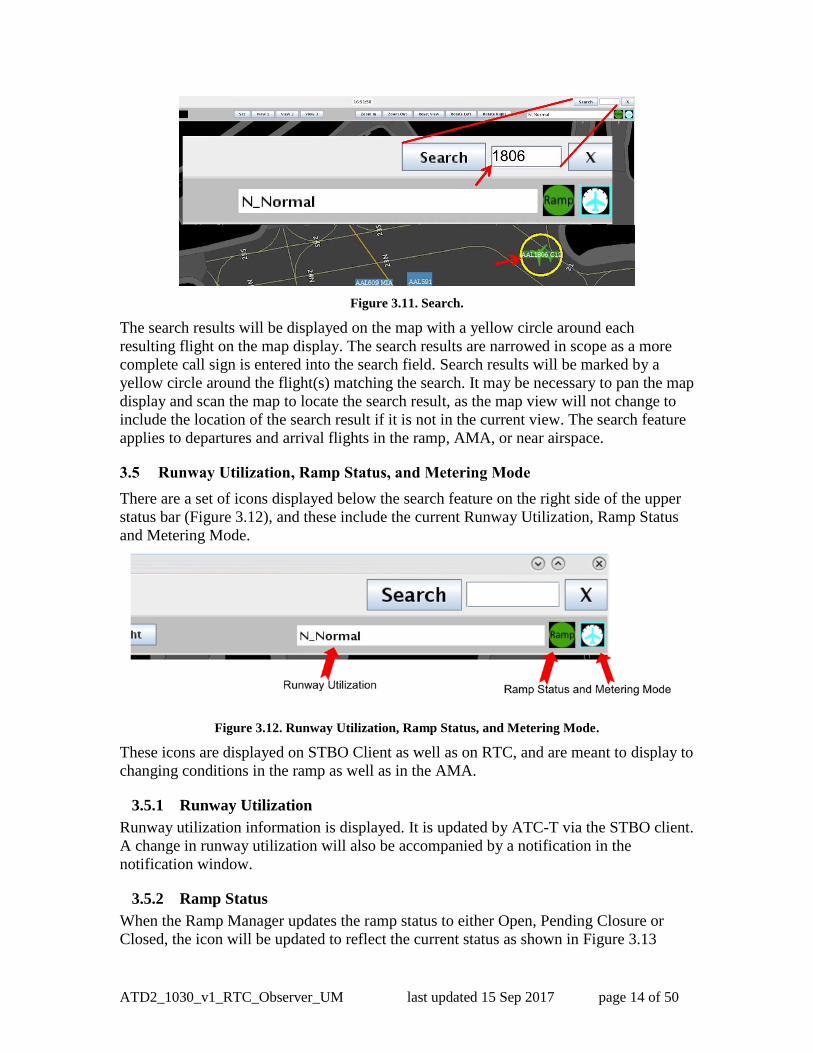
Search for a flight on the RTC map using the alphanumeric search feature (Figure 3.11). 262
Type in the call sign or flight number for a flight, a five-letter name for a departure fix, or 263
a 3 letter ID for a destination airport. 264
Step 1: Set the display to a desired view.
Step 2: Click on Set.
Step 3: Click on either View 1, View2, or View 3 to save this view.
Step 4: Change the display to another desired view and repeat above steps until all
three views are saved.
Step 5: Click on View 1, View 2, or View 3 to quickly toggle between saved views.
ATD2_1030_v1_RTC_Observer_UM last updated 15 Sep 2017 page 14 of 50
265
Figure 3.11. Search. 266
The search results will be displayed on the map with a yellow circle around each 267
resulting flight on the map display. The search results are narrowed in scope as a more 268
complete call sign is entered into the search field. Search results will be marked by a 269
yellow circle around the flight(s) matching the search. It may be necessary to pan the map 270
display and scan the map to locate the search result, as the map view will not change to 271
include the location of the search result if it is not in the current view. The search feature 272
applies to departures and arrival flights in the ramp, AMA, or near airspace. 273
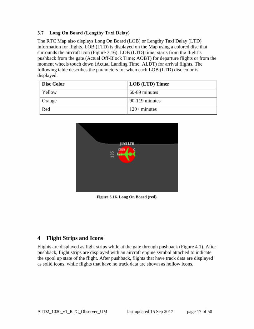
3.5 Runway Utilization, Ramp Status, and Metering Mode 274
There are a set of icons displayed below the search feature on the right side of the upper 275
status bar (Figure 3.12), and these include the current Runway Utilization, Ramp Status 276
and Metering Mode. 277
278
Figure 3.12. Runway Utilization, Ramp Status, and Metering Mode. 279
These icons are displayed on STBO Client as well as on RTC, and are meant to display to 280
changing conditions in the ramp as well as in the AMA. 281
3.5.1 Runway Utilization 282
Runway utilization information is displayed. It is updated by ATC-T via the STBO client. 283
A change in runway utilization will also be accompanied by a notification in the 284
notification window. 285
3.5.2 Ramp Status 286
When the Ramp Manager updates the ramp status to either Open, Pending Closure or 287
Closed, the icon will be updated to reflect the current status as shown in Figure 3.13 288

ATD2_1030_v1_RTC_Observer_UM last updated 15 Sep 2017 page 15 of 50
below. An update to the ramp status will also be accompanied by a notification in the 289
notification window to both the ATC-T on the STBO Client and to RTC for the ramp 290
tower. 291
292
293
Figure 3.13. Ramp Status Icons. 294
3.5.3 Metering Mode 295
The ramp manger can set metering modes for the ramp using RMTC, and the current 296
metering mode is shown on the upper status bar as shown in Figure 1.1. The three 297
metering modes available are: No Metering, Departure Sequencing, and Surface Time 298
Based Metering Mode (refer to Section 6.1). When the ramp manager updates the 299
metering mode, one of three metering mode icons will be displayed, as shown in Figure 300
3.14 below. 301
302
Figure 3.14. Metering Mode Icons. 303
304

ATD2_1030_v1_RTC_Observer_UM last updated 15 Sep 2017 page 16 of 50
A notification of the change in metering mode will also be provided to the notification 305
window for both RTC and STBO. If Departure Sequencing is selected on RMTC, the 306
target queue length as set by the ramp manager will be displayed inside the green 307
departure sequencing icon, and included in the notification as well. A notification is also 308
sent to all the users if Surface Time Based Metering mode is selected on RMTC (refer to 309
Section 7.1: RMTC Tools Menu: Metering Modes). 310
3.6 Departure and Arrival Count Boxes and Lists 311
The Departure Count boxes are located on the bottom right side of the display. The 312
numerator in the runway count box displays the number of flights that have been released 313
to either the eastbound (blue) or westbound (brown) runway, 18L/36R and 18C/36C, 314
respectively. The denominator reflects the number of flights that have been placed on 315
hold to the eastbound and westbound runways. 316
The Near Arrival Count box may also be displayed by selecting that option in the Map 317
Options menu. The Near Arrival Count reflects all arrivals expected in the next 10 318
minutes. 319
All three departure and arrival lists may also be opened by clicking on any of the 320
departure or arrival count boxes on the bottom right of the display (Figure 3.15) below. 321
322
Figure 3.15. Departure and Arrival Count and Lists. 323
324
325
326
327
328
ATD2_1030_v1_RTC_Observer_UM last updated 15 Sep 2017 page 17 of 50
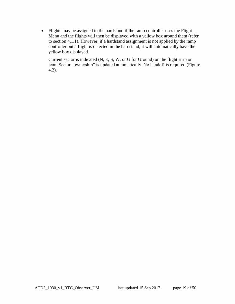
3.7 Long On Board (Lengthy Taxi Delay) 329
The RTC Map also displays Long On Board (LOB) or Lengthy Taxi Delay (LTD) 330
information for flights. LOB (LTD) is displayed on the Map using a colored disc that 331
surrounds the aircraft icon (Figure 3.16). LOB (LTD) timer starts from the flight’s 332
pushback from the gate (Actual Off-Block Time; AOBT) for departure flights or from the 333
moment wheels touch down (Actual Landing Time; ALDT) for arrival flights. The 334
following table describes the parameters for when each LOB (LTD) disc color is 335
displayed. 336
Disc Color LOB (LTD) Timer
Yellow 60-89 minutes
Orange 90-119 minutes
Red 120+ minutes
337
338
Figure 3.16. Long On Board (red). 339
340
341
342
343
4 Flight Strips and Icons 344
Flights are displayed as fight strips while at the gate through pushback (Figure 4.1). After 345
pushback, flight strips are displayed with an aircraft engine symbol attached to indicate 346
the spool up state of the flight. After pushback, flights that have track data are displayed 347
as solid icons, while flights that have no track data are shown as hollow icons. 348
349

ATD2_1030_v1_RTC_Observer_UM last updated 15 Sep 2017 page 18 of 50
350 Figure 4.1. Flight Strips and Icons. 351
4.1 Flight Entries and Right Click Menu: Updating flight state 352
Flight state updates based on ramp controller entries are reflected on the RTC as well as 353
throughout the entire ATD-2 system and are important for situational awareness of 354
current flight state for the entire system including STBO. When a flight requests 355
pushback approval and the ramp controller enters pushback approval, then the system 356
updates with this data for each state change; the flight has called ready and it has been 357
given pushback approval. The entire ATD-2 system reflects the updated state of each 358
flight accordingly and the algorithms use this updated information to provide correct 359
predictions. 360
361
4.1.1 Departures and Arrivals, Colors, Flight States, Solid and Hollow icons 362
The different colors, symbols, and flight state definitions are shown in Figure 4.2. 363
Arrival flights are green. Click on any arrival icon to draw a tether line to the 364
assigned gate. 365
Departure flights are blue if eastbound, brown if westbound. 366
After pushback, flight strips are displayed with an aircraft engine symbol 367
Flights that have track data are displayed as a solid icon. Hollow icons indicate 368
flights that do not have track data (have not yet received it or have lost it). 369
Heavy flights are marked with an orange and white border on the flight strip and a 370
orange and white box around the icon. 371
A flight given a priority flight status will have a green border around the flight 372
strip and a green box around the icon. Flights are designated as priority flights 373
using the ramp manager’s list feature (refer to Section 6) or by the sector 374
controller by using the Flight Menu (refer to Section 7). 375
ATD2_1030_v1_RTC_Observer_UM last updated 15 Sep 2017 page 19 of 50
Flights may be assigned to the hardstand if the ramp controller uses the Flight 376
Menu and the flights will then be displayed with a yellow box around them (refer 377
to section 4.1.1). However, if a hardstand assignment is not applied by the ramp 378
controller but a flight is detected in the hardstand, it will automatically have the 379
yellow box displayed. 380
Current sector is indicated (N, E, S, W, or G for Ground) on the flight strip or 381
icon. Sector “ownership” is updated automatically. No handoff is required (Figure 382
4.2). 383
384

ATD2_1030_v1_RTC_Observer_UM last updated 15 Sep 2017 page 20 of 50
385
386
387
Figure 4.2. Flight States. 388
389

ATD2_1030_v1_RTC_Observer_UM last updated 15 Sep 2017 page 21 of 50
There may be instances when a flight has no track data (displayed as a hollow icon), then 390
after it does acquire track data, the flight will “snap” to the updated location (now a solid 391
icon). 392 393
Arrivals are displayed as grey discs at the gate after loss of track data (Figure 4.3). To 394
view the arrival flight number (and tail number if available), hover on or select the grey 395
arrival disc. For turnaround flights, the next departure flight strip is displayed up to an 396
hour prior to the airline scheduled departure time, or when the system has acquired data 397
regarding the flight. Arrival flights, if selected, will display the “On” time for the flight as 398
well as the predicted duration of taxi. 399 400
401
Figure 4.3. Arrivals. 402
403
4.1.2 Display of TMIs and Airspace Constraint Information on Flights 404
If applicable, TMI Information and other constraints are displayed on the flight strip for 405
each flight (Figure 4.4. ). Alerting is provided on the sector controller’s display for new 406
and/or updated APREQs, EDCTs, and MITs with blinking yellow highlighted TMI 407
information on the flight. Alerts are also provided on the sector controller’s display for 408
departure fix closures, ground stops and destination airport closures by a blinking red 409
highlight of the departure fix, ground stop, or destination airport on the flight. The ramp 410
controller may acknowledge the blinking alerts by clicking on the flight to stop the 411
blinking; however the information will remain on the flight in yellow or red highlighted 412
text box. 413

ATD2_1030_v1_RTC_Observer_UM last updated 15 Sep 2017 page 22 of 50
414
415
416 Figure 4.4. Flight Alerts 417
418
419
Flights under APREQs are indicated by showing APREQ in a yellow text box on 420
the flight strip. This is for flights that need an APREQ/Call-For-Release (CFR) 421
time, also known as wheels up time or flow time, but have not yet been scheduled 422
by the ATC Tower. If a flight is pushed back prior to getting a CFR time, then 423
APREQ will be shown in a red text box and blink as an alert on the sector 424
controller’s display indicating that this flight still needs to be scheduled. The ramp 425
controller may click on the blinking alert to acknowledge the red APREQ alert 426
and stop the blinking. After the APREQ is scheduled it will be displayed on the 427
strip with the scheduled time after A, e.g., as Ahhmm. It is expected that pilots 428
will obtain the CFR prior to pushback. 429
MIT restriction is displayed on the flight as Mnm highlighted in a yellow text box 430
on the flight, where nm specifies the distance in nautical mile. 431
Flights that are subject to metering will have TMAT displayed after pushback, 432
without the yellow highlighting (see the top of Figure 4.5). EDCT flights display 433
the EDCT time on the flight in a yellow text box “Ehhmm”. 434
Flights with both EDCT and APREQ show “EhhmmQ” while wheels-up time is 435
not scheduled. On receipt of wheels-up time by the system, the EDCT is replaced 436
and only “Ahhmm” is shown. After pushback, flights with an EDCT or a 437
scheduled APREQ will be shown with TMAT highlighted in yellow in the format 438
“Thhmm”. This will be shown until the flight has reached the designated spot; 439
beyond that “Ahhmm” is shown (see the bottom of Figure 4.5). 440

ATD2_1030_v1_RTC_Observer_UM last updated 15 Sep 2017 page 23 of 50
Departure fix Closures are indicated by highlighting the fix in a red text box. 441
Fix changes or Coded Departure Routes (CDRs) are indicated by the highlighting 442
the display of the fix in a yellow text box. 443
Note: If there is an update to the route, then the yellow background will blink for 444
an alert to the change. The ramp controller may click on the flight to stop the 445
blinking alert. It is expected that the pilot shall obtain the new route prior to 446
pushback. 447
Ground Stop (GS) programs are indicated on the flight by displaying the 448
destination airport in a red text box. 449
450
451
452
Figure 4.5. TMAT After Pushback (Yellow if TMI). 453
APREQ and EDCT flights will always have a recommended hold time as shown in 454
Figure 4.5, based on the release time (i.e., APREQ/CFR release time or EDCT time). 455
Recommended hold times and how they are displayed is discussed in greater detail in the 456
Metering Modes section, Section 6. 457

ATD2_1030_v1_RTC_Observer_UM last updated 15 Sep 2017 page 24 of 50
458
Figure 4.6. APREQ and EDCT Flights: Always Display Hold advisory. 459
4.1.2.1 TMI flights will have a Release Advisory from the Hardstand 460
If sent to the Hardstand, any flight that has an EDCT or a scheduled APREQ/CFR time 461
will also have a Release Advisory to guide this flight’s release from the Hardstand in 462
time to meet the TMAT time, which, in turn is based on the flight’s being able to comply 463
with the TMI. The Release Advisory, displayed in cyan blue, will count down to the time 464
the flight should be released to be able to meet the TMAT time (Figure 4.7). If the flight 465
has not been released from the Hardstand prior to the countdown reaching zero, a Red 466
“Release” alert (Figure 4.8) will be displayed for that flight. 467
468
469
Figure 4.7. TMI Flight: Release Advisory. 470

ATD2_1030_v1_RTC_Observer_UM last updated 15 Sep 2017 page 25 of 50
471
Figure 4.8. Alert to Release From Hardstand. 472
473
5 Flight Menu 474
Double click a flight strip or icon to open the Flight Menu for any departure (Figure 5.1) 475
or arrival (Figure 5.2) flight. The flight menu may also be opened for a flight using the 476
right mouse click menu. Select Flight Menu from right click mouse menu to open the 477
Flight Menu for any arrival or departure flight. The Flight Menu is available for each 478
flight to view various flight details for that flight. 479
480
481
Figure 5.1. Departure Flight Menu. 482
ATD2_1030_v1_RTC_Observer_UM last updated 15 Sep 2017 page 26 of 50
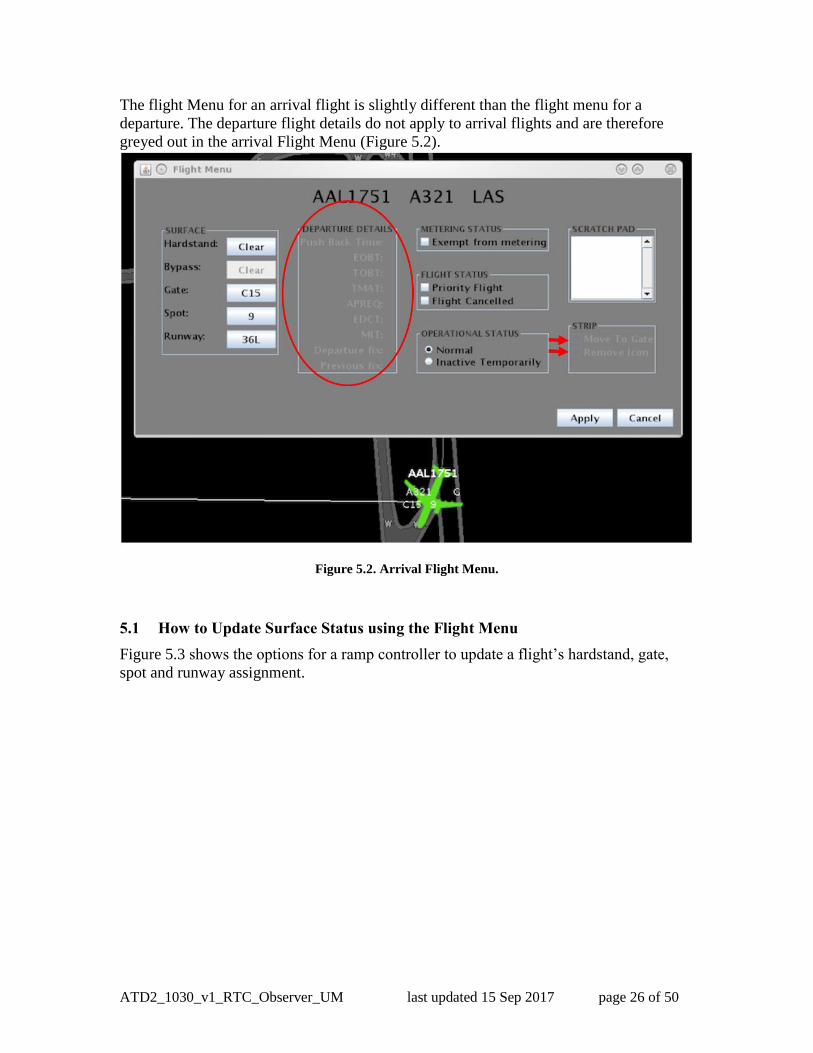
The flight Menu for an arrival flight is slightly different than the flight menu for a 483
departure. The departure flight details do not apply to arrival flights and are therefore 484
greyed out in the arrival Flight Menu (Figure 5.2). 485
486
Figure 5.2. Arrival Flight Menu. 487
488
5.1 How to Update Surface Status using the Flight Menu 489
Figure 5.3 shows the options for a ramp controller to update a flight’s hardstand, gate, 490
spot and runway assignment. 491

ATD2_1030_v1_RTC_Observer_UM last updated 15 Sep 2017 page 27 of 50
492
Figure 5.3. Update Surface Flight Data. 493
Figure 5.4 shows the options for a ramp controller to assign flights to the hardstand. 494
495
496
Figure 5.4. Hardstand Assignment. 497
498
Figure 5.5 shows the options for a ramp controller to update the gate assignment. 499

ATD2_1030_v1_RTC_Observer_UM last updated 15 Sep 2017 page 28 of 50
500
501
Figure 5.5. Gate Assignment. 502
Figure 5.6 shows the method for a ramp controller to update the spot assignment. 503
504
505
Figure 5.6. Spot Assignment. 506
507

ATD2_1030_v1_RTC_Observer_UM last updated 15 Sep 2017 page 29 of 50
Figure 5.7 shows the method for a ramp controller to make a runway change for 508
operational necessity. 509
510
Figure 5.7. Runway Change (For Operational Necessity). 511
This procedure results in a change in the direction of the flight so it may change from 512
blue to brown or vice versa to reflect the updated runway. The runway will also be 513
highlighted in green on the flight strip (Figure 5.8). This change will also be reflected on 514
the ATC-T’s STBO Client timeline, as the flight will be moved to the new runway 515
timeline. Runway change cannot be made on Arrivals. 516
517
518
Figure 5.8. Updated Runway in Green Highlight. 519

ATD2_1030_v1_RTC_Observer_UM last updated 15 Sep 2017 page 30 of 50
5.1.1 Departure Details 520
Under the Departure Details section of the Flight Menu (Figure 5.9), all times pertaining 521
to the flight are listed, including times for any TMIs. The Departure Fix and any updated 522
departure fix information are also shown here. 523
524
Figure 5.9. Departure Details. 525
P-time: This is the airline scheduled pushback time 526
EOBT (Earliest Off Block Time): This is the expected pushback time or when the 527
flight will be ready based on airline updates 528
TOBT (Target Off Block Time): This is the time the tactical scheduler plans for 529
the flight to pushback 530
TMAT (Target Movement Area entry Time): This is the time the tactical 531
scheduler plans for the flight to be at the spot 532
APREQ: If the flight is under APREQ/CFR restriction, the release time will be 533
displayed here after the APREQ/CFR is scheduled 534
EDCT: If the flight is under a Ground Delay Program (GDP), the EDCT will be 535
displayed here 536
MIT: If there is an MIT restriction for this flight, it will be displayed here 537
Departure Fix: The assigned departure fix for the flight is shown here 538
Previous Fix: If there was an update to the assigned fix, then the previously 539
assigned fix is listed here 540
541
542
5.1.2 Metering Status, Flight Status and Operational Status 543
The status of a flight may be viewed in detail with the Flight Menu Metering, Flight, or 544
Operational Status options (Figure 5.10). 545

ATD2_1030_v1_RTC_Observer_UM last updated 15 Sep 2017 page 31 of 50
546
Figure 5.10. Metering, Flight, Operational Status. 547
A flight is exempted from Surface Time Based Metering (STBM) when the checkbox for 548
“Exempt from metering” is selected; refer to Section 6 for an explanation of Metering 549
Modes. Certain flights may be automatically exempt from metering, such as military 550
flights or General Aviation flights. International flights are not automatically exempt 551
from metering; if they are, they will be marked for exemption as shown in Figure 5.10. 552
A flight is designated as a priority flight if the “Priority flight” checkbox is checked. The 553
flight will be on the ramp manager’s Priority Flight List (refer to Section 7.5) and will 554
have a green border around the flight strip (Figure 5.11). 555
556
Figure 5.11. Canceled and Priority Flights. 557

ATD2_1030_v1_RTC_Observer_UM last updated 15 Sep 2017 page 32 of 50
In case cancellation status is not received via the data feeds, the sector controller may 558
need to cancel the flight. When a flight is cancelled, a red X watermark is on the flight 559
(Figure 5.11). The flight will then time out within a minute and the flight strip will turn 560
into a grey icon on the display. If the flight is scheduled for departure again and that data 561
is received from the data feeds, a flight strip will appear at the gate. It will be deleted 562
automatically when the underlying flight is deleted by the system 4 hours after it is 563
cancelled. 564
The Operational status for a flight can be seen on the Flight Menu (Figure 5.10). 565
Operational status refers specifically to how the STBM tool considers the flight (refer to 566
Section 6). Normal status means the flight is expected to proceed as a normal/ regular 567
flight and is treated accordingly by the STBM. “Inactive Temporarily” means that the 568
flight has been temporarily removed by the controller from normal consideration in the 569
STBM system, for example when there is a quickly remedied maintenance issue. 570
5.1.3 Scratch Pad entry, Return to Gate, and Remove Icon 571
The Flight Menu for any flight has a scratchpad feature (Figure 5.12). 572
573
Figure 5.12. Scratch Pad, Return to Gate, Remove Icon. 574
The “Remove Icon” checkbox shown in Figure 5.12 may be checked by the ramp 575
controller to permanently remove the flight from the RTC display. 576
If the departure flight has been mistakenly cleared to proceed, the “Return to Gate” 577
checkbox may be checked by the ramp controller. 578
6 Metering Modes 579
There are three metering modes possible in RTC and RMTC: No Metering, Departure 580
Sequencing, and Surface Time Based Metering (STBM). Departure Sequencing mode 581
refers to the legacy metering historically used in the AAL ramp. STBM mode provides 582
tactical gate hold recommendations generated by the scheduler based on multiple inputs, 583
including scheduled departure times, EOBTs, nominal taxi times, and demand at the 584
runway. STBM is described in greater detail in the next section. 585

ATD2_1030_v1_RTC_Observer_UM last updated 15 Sep 2017 page 33 of 50
6.1 Surface Time Based Metering (STBM) 586
STBM is ATD-2’s surface metering tool to alleviate surface congestion in the near-term 587
tactical time frame. The tool provides gate hold recommendations that are expected to be 588
treated as advisories by the ramp controller. STBM meters departures at the gate and 589
provides gate hold advisories based on a selected target excess queue time (or excess taxi 590
time) to the runway. The excess queue time is the acceptable amount of additional taxi 591
time the departures may spend while they are taxiing on the surface and waiting in the 592
runway queue before taking off. Simply put, when the demand from the ramp is predicted 593
to exceed the set value, the STBM starts recommending hold times at the gate. 594
The STBM uses Earliest Off Block Times (EOBTs) and un-delayed taxi time estimations 595
to predict when aircraft will arrive at the runways. Based on these predictions and 596
operational constraints, STBM generates a schedule that calculates Target Takeoff Times 597
(TTOTs) at the runways, Target Movement Area entry Times (TMAT) at the spots, and 598
Target Off Block Times (TOBT) at the gates. The TOBT is used to provide gate hold 599
recommendations. 600
The metering tool considers the demand and capacity imbalance for every departure 601
runway before recommending gate holds. It may be observed, at times, that there are no 602
gate holds recommended for flights departing from one runway, while at the same time 603
there are gate holds recommended for flights departing from another runway. STBM 604
takes into consideration the following: APREQs, EDCTs, taxi time estimates both in 605
ramp and on the AMA, gate pushback duration estimates, flight spacing requirements 606
based on the type of runway operations (such as converging runway or dual use 607
operations), and runway crossings. Finally, STBM takes into consideration EOBT 608
quality to determine the level of certainty when generating runway schedules for 609
departures and their corresponding gate hold recommendations (see Section 6.1.4). 610
The tactical surface scheduler is expected to run all the time in the background. However, 611
the Ramp Manager can turn metering on and off to manage any demand/capacity 612
imbalances according to strategy. 613
When the Ramp Manager decides to turn on time-based metering, he or she will choose a 614
target level of excess queue time in the AMA. There are three values to choose from: 14, 615
12 and 10 minutes. However, a custom value may be entered (Figure 7.7). The higher the 616
excess queue time in the AMA is set, the lower the gate hold times are recommended by 617
the metering tool. The selection of these target excess queue times is described in Section 618
7.3. 619
In addition to the target excess queue time value, there are lower and upper thresholds to 620
this value. The lower and upper thresholds determine when to show recommended gate 621
hold times on the RTC display. The STBM will start showing recommended gate hold 622
times when the predicted maximum excess queue time exceeds the upper threshold, and 623
will stop showing these hold times when the predicted minimum excess queue time 624
reaches the lower threshold. 625
The upper threshold establishes a target of maximum of excess queue times. Hold times 626
will then be assigned to prevent departures from being delayed beyond the upper 627
threshold. The lower threshold establishes the minimum of excess taxi times that 628
ATD2_1030_v1_RTC_Observer_UM last updated 15 Sep 2017 page 34 of 50
qualifies for metering. Flights with the minimum excess taxi time below that threshold 629
will not get assigned a hold time. 630
The target values already come with pre-set values for both the lower and upper threshold 631
of excess queue time. These pre-set threshold values are intended to provide a reasonable 632
duration and amount of gate holds. However, both threshold values can be custom set by 633
the ramp manager at any time. Once the lower and upper thresholds are set, the STBM 634
scheduler algorithm will generate recommended hold times based on these values and 635
will display gate hold advisories on the RTC display. 636
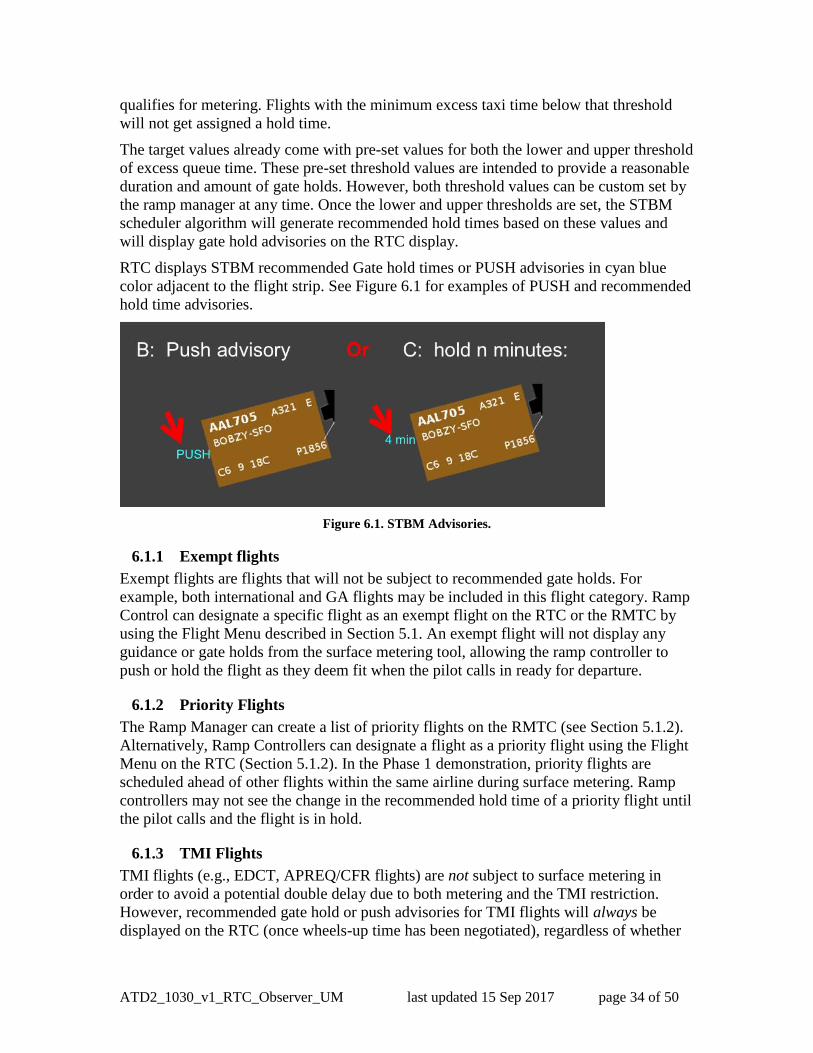
RTC displays STBM recommended Gate hold times or PUSH advisories in cyan blue 637
color adjacent to the flight strip. See Figure 6.1 for examples of PUSH and recommended 638
hold time advisories. 639
640
Figure 6.1. STBM Advisories. 641
6.1.1 Exempt flights 642
Exempt flights are flights that will not be subject to recommended gate holds. For 643
example, both international and GA flights may be included in this flight category. Ramp 644
Control can designate a specific flight as an exempt flight on the RTC or the RMTC by 645
using the Flight Menu described in Section 5.1. An exempt flight will not display any 646
guidance or gate holds from the surface metering tool, allowing the ramp controller to 647
push or hold the flight as they deem fit when the pilot calls in ready for departure. 648
6.1.2 Priority Flights 649
The Ramp Manager can create a list of priority flights on the RMTC (see Section 5.1.2). 650
Alternatively, Ramp Controllers can designate a flight as a priority flight using the Flight 651
Menu on the RTC (Section 5.1.2). In the Phase 1 demonstration, priority flights are 652
scheduled ahead of other flights within the same airline during surface metering. Ramp 653
controllers may not see the change in the recommended hold time of a priority flight until 654
the pilot calls and the flight is in hold. 655
6.1.3 TMI Flights 656
TMI flights (e.g., EDCT, APREQ/CFR flights) are not subject to surface metering in 657
order to avoid a potential double delay due to both metering and the TMI restriction. 658
However, recommended gate hold or push advisories for TMI flights will always be 659
displayed on the RTC (once wheels-up time has been negotiated), regardless of whether 660

ATD2_1030_v1_RTC_Observer_UM last updated 15 Sep 2017 page 35 of 50
surface metering is turned on or off, in order to assist the ramp controller in releasing 661
these flights to meet their TMI wheels-up time. Once the flight pushes back, instead of 662
the APREQ or EDCT times, a TMAT will be shown with a yellow background on the 663
flight strip. Note that a large number of TMI flights in the system will impact demand 664
and may increase gate hold times for flights that are subject to metering. 665
6.1.4 EOBTs and Gate Hold Time Advisories 666
STBM takes Earliest Off Block Times (EOBT) that can also be described as flights’ 667
estimated ready times and uses those to generate gate hold advisories. EOBT is being 668
calculated by the airline based on various factors such as percentage of passengers 669
boarded and baggage loaded. The STBM scheduler allocates runway departure slots at 670
the gates in order of consideration based on the quality of the flight’s EOBT. The order of 671
consideration increases as a flight’s predictability of its runway takeoff time increases. 672
For example, a taxiing flight has a higher order of consideration than that of a flight at the 673
gate. In current scheduler implementation, an aircraft moves from the Uncertain group to 674
the Planning group, to the Ready group, and then on to an Out group, a Taxi group, and 675
finally to the Queue (see Figure 6.2), and therefore, as the level of certainty about actual 676
pushback times increases, flights are moved from the ‘Uncertain’ to the ‘Planning” 677
group. 678
6.1.5 ‘Planning’ Group 679
The flights that have reliable EOBTs are placed in the Planning group. This takes place 680
when flights’ EOBTs fall within a specified scheduling accuracy window, e.g., 10 681
minutes. Once flights are in the Planning group, STBM displays gate holds or pushback 682
advisories on the RTC. Pushback advisories are updated at every scheduling cycle (i.e., 683
10 seconds). See Figure 6.2 for a depiction of the scheduling groups as well as the 684
advisories shown on RTC for flights in the Planning group. Ramp controllers are 685
expected to act on pushback advisories only after the pilot calls ready for pushback. The 686
expectation is that pilots will call in by at least 5 minutes past their EOBTs. If they do 687
not, their flights will be put in the Uncertain group. This prevents flights that are late to 688
push from adding unnecessary delay to other flights. Flights that are past the window of 689
their EOBTs, and therefore have been put in the Uncertain group, will receive a gate hold 690
or pushback advisory as soon as pilots call for pushback (see Section 5.1.1). 691

ATD2_1030_v1_RTC_Observer_UM last updated 15 Sep 2017 page 36 of 50
692 Figure 6.2. Planning Group. 693
6.1.6 “Ready” Group 694
Flights are considered to be in the ‘Ready group’ when pilots call in for pushback 695
clearance. The Ramp Controllers either put flights on hold or push them based on the 696
advisories provided by the scheduler for these flights. The flights will remain in the 697
Ready group if the flights are on hold. Otherwise, the flights will be placed in the Out 698
group, once they begin pushback (Figure 6.3). 699

ATD2_1030_v1_RTC_Observer_UM last updated 15 Sep 2017 page 37 of 50
700
Figure 6.3. Ready Group. 701
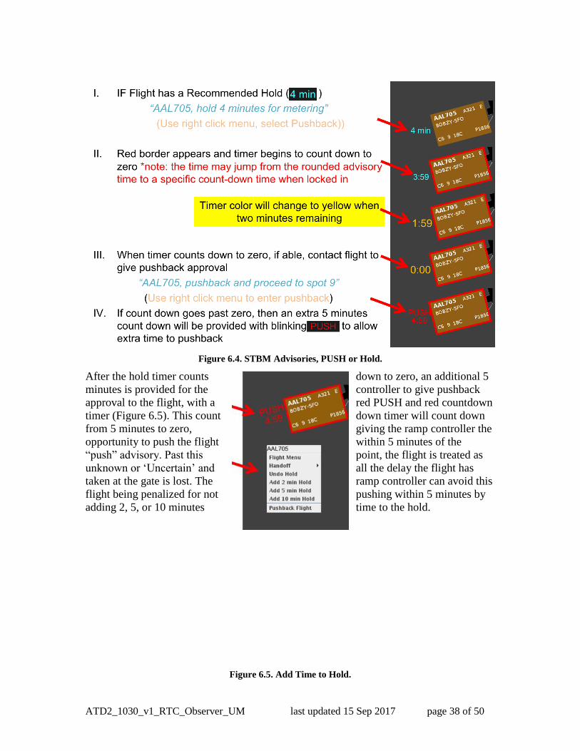
If there is a recommended gate hold time provided by the STBM advisory, the Ramp 702
Controller is expected to hold the flight, providing the hold time to the Pilot. The Ramp 703
Controller places a hold on the flight by sliding the flight strip toward the gate (Figure 704
6.4). In the examples shown in the figures above and below, placing a flight on hold 705
places a red border around the flight strip, and the 4-minute cyan blue hold timer begins 706
counting down the recommended hold time. 707
ATD2_1030_v1_RTC_Observer_UM last updated 15 Sep 2017 page 38 of 50
708
709
Figure 6.4. STBM Advisories, PUSH or Hold. 710
After the hold timer counts 711 down to zero, an additional 5
minutes is provided for the 712 controller to give pushback
approval to the flight, with a 713 red PUSH and red countdown
timer (Figure 6.5). This count 714 down timer will count down
from 5 minutes to zero, 715 giving the ramp controller the
opportunity to push the flight 716 within 5 minutes of the
“push” advisory. Past this 717 point, the flight is treated as
unknown or ‘Uncertain’ and 718 all the delay the flight has
taken at the gate is lost. The 719 ramp controller can avoid this
flight being penalized for not 720 pushing within 5 minutes by
adding 2, 5, or 10 minutes 721 time to the hold.
722
723
724
725
726
727
728
729
730
Figure 6.5. Add Time to Hold. 731
ATD2_1030_v1_RTC_Observer_UM last updated 15 Sep 2017 page 39 of 50
732
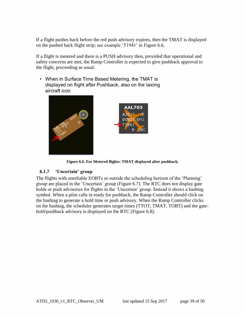
If a flight pushes back before the red push advisory expires, then the TMAT is displayed 733
on the pushed back flight strip; see example ‘T1941’ in Figure 6.6. 734
735
If a flight is metered and there is a PUSH advisory then, provided that operational and 736
safety concerns are met, the Ramp Controller is expected to give pushback approval to 737
the flight, proceeding as usual. 738
739
740 Figure 6.6. For Metered flights: TMAT displayed after pushback. 741
6.1.7 ‘Uncertain’ group 742
The flights with unreliable EOBTs or outside the scheduling horizon of the ‘Planning’ 743
group are placed in the ‘Uncertain’ group (Figure 6.7). The RTC does not display gate 744
holds or push advisories for flights in the ‘Uncertain’ group. Instead it shows a hashtag 745
symbol. When a pilot calls in ready for pushback, the Ramp Controller should click on 746
the hashtag to generate a hold time or push advisory. When the Ramp Controller clicks 747
on the hashtag, the scheduler generates target times (TTOT, TMAT, TOBT) and the gate- 748
hold/pushback advisory is displayed on the RTC (Figure 6.8). 749

ATD2_1030_v1_RTC_Observer_UM last updated 15 Sep 2017 page 40 of 50
750
Figure 6.7. Uncertain Group. 751
752
Figure 6.8. Uncertain Group, Hashtag Flights. 753
A flight in the ‘Uncertain’ group with a good quality EOBT will automatically progress 754
to the ‘Planning’ group (Figure 6.2). 755
6.1.8 ‘Out’, ‘Taxi’ and ‘Queue’ Groups 756
Flights are considered in the ‘Out’ group when flights have actually started pushing back 757
and have an engine symbol next to them. Flights are the ‘Taxi’ group once they have 758
started taxiing or surveillance has picked the flights up and they are displayed as solid 759
aircraft icons on the RTC (see Figure 6.9). 760

ATD2_1030_v1_RTC_Observer_UM last updated 15 Sep 2017 page 41 of 50
761
Figure 6.9. Out, Taxi and Queue Groups. 762
763
ATD2_1030_v1_RTC_Observer_UM last updated 15 Sep 2017 page 42 of 50
7 RMTC 764
The Ramp Management Traffic Console (RMTC) is designed to support the ramp 765
manager’s role. It provides the same RTC functions as described in the previous sections, 766
plus additional functions that pertain to the ramp manager. The additional functions are 767
accessed in the RMTC Tools Menu and are described below. 768
The functions available to the Ramp Manager are listed under the “Tools Menu” in the 769
upper left side of the RMTC (see Figure 7.1). This menu gives access to the metering 770
modes, the operational status of the ramp, and the list of priority flights. 771
772
Figure 7.1. Functions under the RMTC “Tools” menu. 773
7.1 RMTC Tools Menu: Metering Modes 774
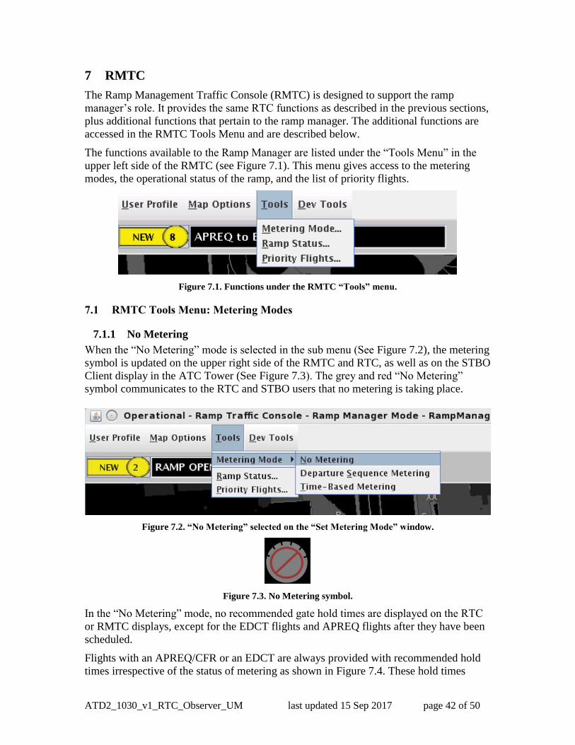
7.1.1 No Metering 775
When the “No Metering” mode is selected in the sub menu (See Figure 7.2), the metering 776
symbol is updated on the upper right side of the RMTC and RTC, as well as on the STBO 777
Client display in the ATC Tower (See Figure 7.3). The grey and red “No Metering” 778
symbol communicates to the RTC and STBO users that no metering is taking place. 779
780
781
Figure 7.2. “No Metering” selected on the “Set Metering Mode” window. 782
783
Figure 7.3. No Metering symbol. 784
In the “No Metering” mode, no recommended gate hold times are displayed on the RTC 785
or RMTC displays, except for the EDCT flights and APREQ flights after they have been 786
scheduled. 787
Flights with an APREQ/CFR or an EDCT are always provided with recommended hold 788
times irrespective of the status of metering as shown in Figure 7.4. These hold times 789

ATD2_1030_v1_RTC_Observer_UM last updated 15 Sep 2017 page 43 of 50
advise the ramp controllers when these flights should push to comply to their release time 790
at the runway. 791
Figure 7.4. Scheduled APREQ and EDCT always have a recommeded hold time
Note that the STBM scheduler is always running in the background and continuously 792
assesses the need for gate hold times. The hold times are simply not displayed on the 793
RTC and RMTC when the No Metering Mode is selected. 794
7.2 Departure Sequence Metering 795
When the “Departure Sequence Metering” mode is selected in the “Set Metering Mode” 796
window (see Figure 7.5), the metering symbol is updated on the upper right side of the 797
RMTC and RTC, as well as on the STBO Client display in the Tower (See Figure 7.6). 798
The green symbol displays the target queue length as entered by the Ramp Manager. In 799
Departure Sequencing, the queue includes all flights that have been released from the 800
gate to the runway. 801
802
803
Figure 7.5 “Departure Sequence Metering” is selected on the “Set Metering Mode” window. 804
805
806

ATD2_1030_v1_RTC_Observer_UM last updated 15 Sep 2017 page 44 of 50
807
Figure 7.6 Departure Sequence Metering symbol with the target queue size value. 808
In Departure Sequencing Mode, the STBM scheduler will not recommend specific gate 809
holds to meet a target queue size at the runway. The Ramp Controllers are expected to 810
manage the aircraft pushbacks manually based on the runway flight lists (refer to Section 811
3.6). 812
7.3 Surface Time Based Metering (STBM) 813
When the “Surface Time Based Metering” mode is selected in the “Set Metering Mode” 814
window (see Figure 7.7), the metering symbol is updated on the upper right side of the 815
RMTC and RTC, as well as on the STBO Client display in the ATC Tower (see Figure 816
7.8). This symbol communicates to the RTC and STBO users that the current Metering 817
Mode is STBM. 818
819
Figure 7.7 Surface Time Based Metering setting window. 820
821
822
Figure 7.8 STBM Metering symbol. 823
824

ATD2_1030_v1_RTC_Observer_UM last updated 15 Sep 2017 page 45 of 50
Target Excess Queue Time 825
When the “Surface Time Based Metering” mode is selected, the STBM scheduler will 826
meter departures at the gate based on the selected target excess queue time to the runway. 827
The excess queue time is the acceptable amount of additional time the departures spend 828
taxiing before taking off. Simply put, when the demand for the runway is predicted to 829
exceed the set value, the scheduler starts recommending hold times. 830
The target values displayed in Figure 7.7 are pre-set for both the lower and upper 831
threshold of excess queue time (currently 10 to 14 minutes). These threshold values are 832
intended to provide a reasonable duration and amount of gate holds. However, both 833
threshold values can be custom set at any time. 834
To view data and graphics that can be used to determine the desired target excess taxi 835
queue time and threshold levels, refer to the DASH User Manual for instructions on how 836
to use the DASH tool. 837
7.4 RMTC Tools Menu: Ramp Status 838
As part of the data exchange between the Ramp and the Tower, the Ramp Manager can 839
indicate any change of operational status of the ramp (i.e., whether it is open, pending 840
closure, or closed) on the RMTC (see Figure 7.9). The change of status is then reflected 841
on both the RTC and the STBO Client display in the ATC Tower. The symbol of the 842
ramp status is updated and a notification is issued as well. 843
844
Note that the STBM scheduler will not know the impact of the ramp closure, and thus 845
gate hold times may no longer make sense. It is up to the Ramp Manager’s discretion to 846
turn STBM off or on during a ramp closure or a pending ramp closure. 847

ATD2_1030_v1_RTC_Observer_UM last updated 15 Sep 2017 page 46 of 50
848
Figure 7.9. Set Ramp Status Window. 849
The status is indicated by a symbol on the upper right side of the RTC and RMTC. This 850
symbol also appears on the ATC- T’s STBO Client display. As can be seen in Figure 851
7.10, the green symbol indicates the ramp is open, the yellow symbol indicates the ramp 852
is pending closure, and the red symbol indicates the ramp is closed. 853
854
855
Figure 7.10 Symbols indicating the ramp status. 856
When changes are made to the Metering Mode or Ramp Status, in addition to the symbol 857
for Metering Mode and Ramp Status being updated, a notification is generated. The new 858
Metering Mode or Ramp Status will be displayed in the Notification Window on the 859
upper left side of the RTC and RMTC, and STBO Client in the Tower, as shown in 860
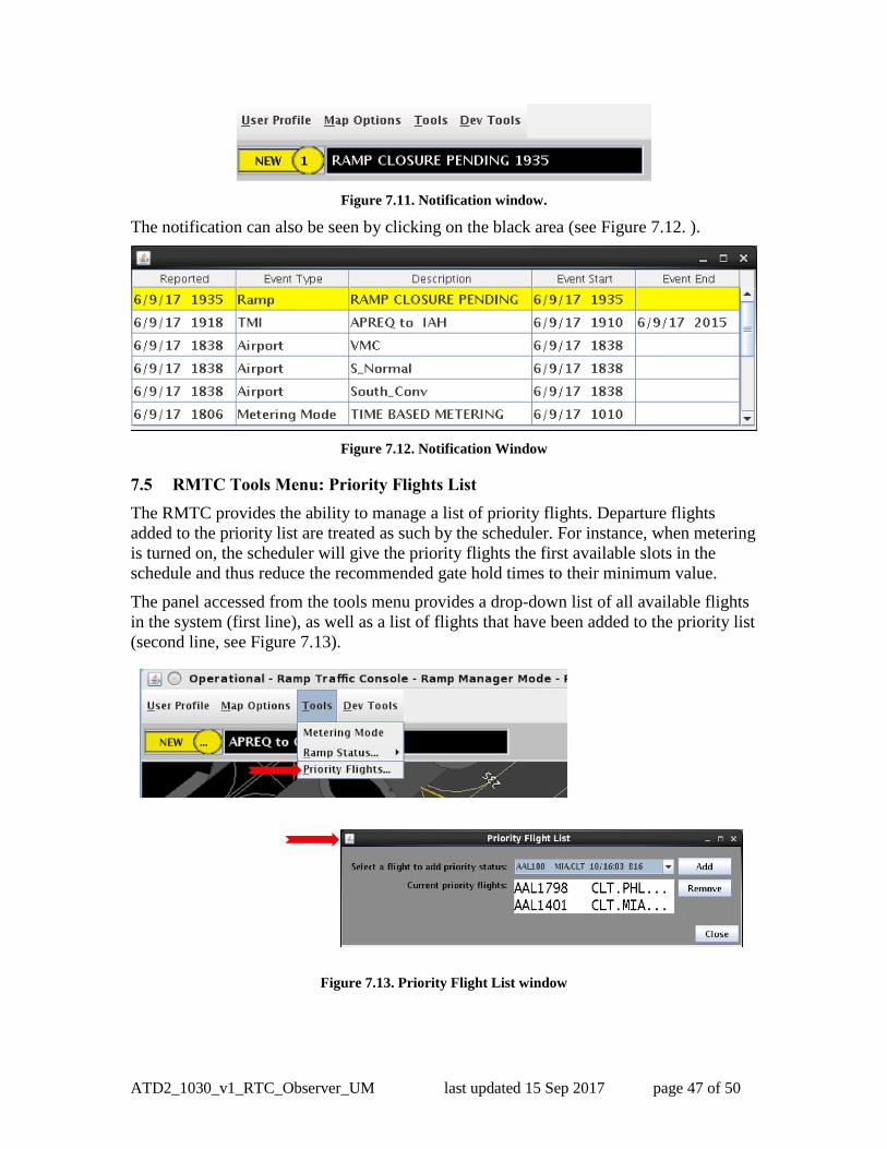
Figure 7.11. 861
ATD2_1030_v1_RTC_Observer_UM last updated 15 Sep 2017 page 47 of 50
862
Figure 7.11. Notification window. 863
The notification can also be seen by clicking on the black area (see Figure 7.12. ). 864
865
Figure 7.12. Notification Window 866
7.5 RMTC Tools Menu: Priority Flights List 867
The RMTC provides the ability to manage a list of priority flights. Departure flights 868
added to the priority list are treated as such by the scheduler. For instance, when metering 869
is turned on, the scheduler will give the priority flights the first available slots in the 870
schedule and thus reduce the recommended gate hold times to their minimum value. 871
The panel accessed from the tools menu provides a drop-down list of all available flights 872
in the system (first line), as well as a list of flights that have been added to the priority list 873
(second line, see Figure 7.13). 874
875
Figure 7.13. Priority Flight List window 876
877
ATD2_1030_v1_RTC_Observer_UM last updated 15 Sep 2017 page 48 of 50
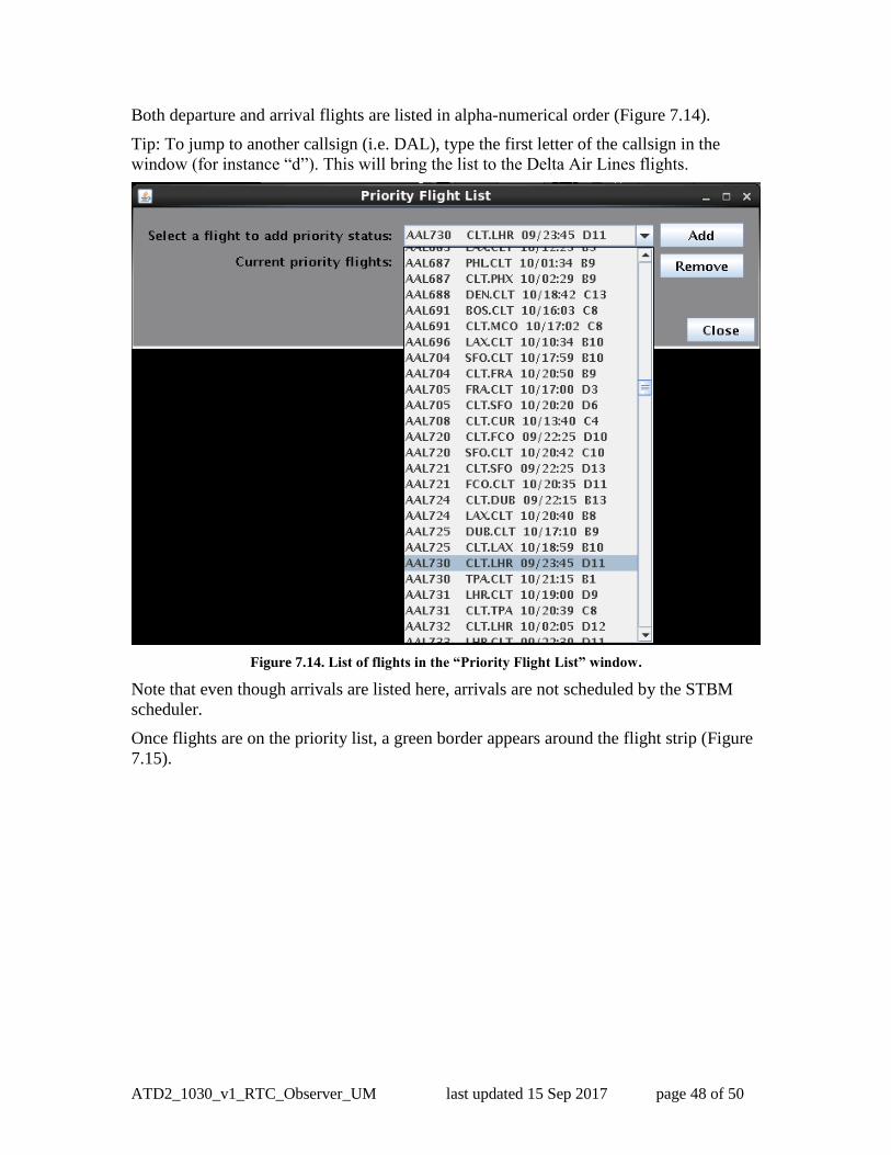
Both departure and arrival flights are listed in alpha-numerical order (Figure 7.14). 878
Tip: To jump to another callsign (i.e. DAL), type the first letter of the callsign in the 879
window (for instance “d”). This will bring the list to the Delta Air Lines flights. 880
881
Figure 7.14. List of flights in the “Priority Flight List” window. 882
Note that even though arrivals are listed here, arrivals are not scheduled by the STBM 883
scheduler. 884
Once flights are on the priority list, a green border appears around the flight strip (Figure 885
7.15). 886

ATD2_1030_v1_RTC_Observer_UM last updated 15 Sep 2017 page 49 of 50
887
Figure 7.15. Priority Flight List and flight strip with green border on the map. 888
889
ATD2_1030_v1_RTC_Observer_UM last updated 15 Sep 2017 page 50 of 50
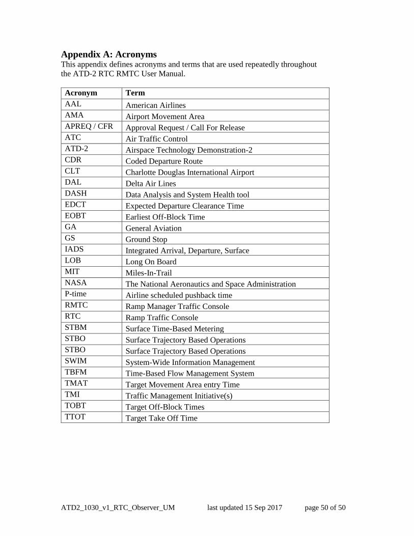
Appendix A: Acronyms 890
This appendix defines acronyms and terms that are used repeatedly throughout 891
the ATD-2 RTC RMTC User Manual. 892
893
Acronym Term
AAL American Airlines
AMA Airport Movement Area
APREQ / CFR Approval Request / Call For Release
ATC Air Traffic Control
ATD-2 Airspace Technology Demonstration-2
CDR Coded Departure Route
CLT Charlotte Douglas International Airport
DAL Delta Air Lines
DASH Data Analysis and System Health tool
EDCT Expected Departure Clearance Time
EOBT Earliest Off-Block Time
GA General Aviation
GS Ground Stop
IADS Integrated Arrival, Departure, Surface
LOB Long On Board
MIT Miles-In-Trail
NASA The National Aeronautics and Space Administration
P-time Airline scheduled pushback time
RMTC Ramp Manager Traffic Console
RTC Ramp Traffic Console
STBM Surface Time-Based Metering
STBO Surface Trajectory Based Operations
STBO Surface Trajectory Based Operations
SWIM System-Wide Information Management
TBFM Time-Based Flow Management System
TMAT Target Movement Area entry Time
TMI Traffic Management Initiative(s)
TOBT Target Off-Block Times
TTOT Target Take Off Time
894
895