Embed Size (px)
Citation preview

www.wackergroup.com
Trench Roller
RT 56-SCRT 82-SC
OPERATOR’S MANUAL
0154652en 014
0508
0 1 5 4 6 5 2 E N


RT /... Table of Contents
wc_bo0154652012enTOC.fm 3
1. Foreword 5
2. Safety Information 6
2.1 Laws Pertaining to Spark Arresters ...................................................... 62.2 Operating Safety .................................................................................. 72.3 Operator Safety while using Internal Combustion Engines .................. 92.4 Service Safety .................................................................................... 102.5 Label Locations .................................................................................. 112.6 Warning and Informational Labels ...................................................... 12
3. Operation 16
3.1 Operation and Service Locations ....................................................... 163.2 Application .......................................................................................... 203.3 Control Features ................................................................................. 203.4 Accessing the Engine or Hydraulic Compartment .............................. 213.5 Accessing the Control Compartment .................................................. 213.6 Control Panel ...................................................................................... 223.7 SmartControl™ Transmitter ............................................................... 243.8 Infra-red System and Control Channels ............................................. 283.9 Before Starting ................................................................................... 303.10 Starting ............................................................................................... 313.11 Stopping ............................................................................................. 323.12 Operation ............................................................................................ 333.13 Position of Operator ........................................................................... 343.14 Range Limits ...................................................................................... 353.15 Operating Characteristics ................................................................... 363.16 Ni-Cad Battery .................................................................................... 363.17 Replacing the Battery Pack ................................................................ 363.18 Charging Transmitter Battery ............................................................. 373.19 Operation on Slopes ........................................................................... 393.20 Tip-overs and Roll-overs .................................................................... 403.21 Articulated Joint Locking Bar .............................................................. 40

Table of Contents RT /...
wc_bo0154652012enTOC.fm 4
4. Maintenance 42
4.1 Transporting Machine ..........................................................................424.2 Lifting Machine ....................................................................................424.3 Job Site Storage ..................................................................................434.4 Storage ................................................................................................444.5 New Machines .....................................................................................444.6 Periodic Maintenance Schedules ........................................................454.7 Hydraulic Oil Requirements .................................................................464.8 Hydraulic Oil Level ..............................................................................464.9 Changing Hydraulic Oil & Filter ...........................................................474.10 Articulated Joint, Steering Cylinder, and Hood Hinges .......................484.11 Cleaning SmartControl™ Transmitter .................................................484.12 Drive Gearcase ...................................................................................494.13 Exciter Lubrication ...............................................................................504.14 Scrapers ..............................................................................................514.15 Shockmounts .......................................................................................514.16 Changing Drums .................................................................................524.17 Battery .................................................................................................534.18 Engine Oil System ...............................................................................544.19 Engine Oil and Filter ............................................................................554.20 Air Cleaner ..........................................................................................564.21 Engine Fuel Delivery System Maintenance .........................................574.22 Fuel Filter ............................................................................................574.23 Priming the Fuel System .....................................................................584.24 Engine Coolant ....................................................................................584.25 Valve Clearances ................................................................................594.26 Adjusting Engine Fan Belt ...................................................................604.27 Basic Troubleshooting .........................................................................62
5. Technical Data 64
5.1 Engine .................................................................................................645.2 Roller ...................................................................................................655.3 Lubrication ...........................................................................................665.4 Sound and Vibration Measurements ...................................................665.5 Dimensions—0009025, 0009026, 0620365, 0620366, 0620397 ........675.6 Dimensions—0620324 ........................................................................675.7 Wiring Schematic—Machine Rev. 121 and lower ...............................685.8 Wiring Schematic—Machine Rev. 122 and higher ..............................70

wc_tx000001gb.fm 5
CALIFORNIA
Proposition 65 Warning:
Engine exhaust, some of its constituents, and certain vehiclecomponents, contain or emit chemicals known to the State ofCalifornia to cause cancer and birth defects or other reproductiveharm.
1. Foreword
This manual provides information and procedures to safely operateand maintain this Wacker model. For your own safety and protectionfrom injury, carefully read, understand and observe the safetyinstructions described in this manual.
Keep this manual or a copy of it with the machine. If you lose thismanual or need an additional copy, please contact WackerCorporation. This machine is built with user safety in mind; however,it can present hazards if improperly operated and serviced. Followoperating instructions carefully! If you have questions about operatingor servicing this equipment, please contact Wacker Corporation.
The information contained in this manual was based on machines inproduction at the time of publication. Wacker Corporation reserves theright to change any portion of this information without notice.
All rights, especially copying and distribution rights, are reserved.
Copyright 2007 by Wacker Corporation.
No part of this publication may be reproduced in any form or by anymeans, electronic or mechanical, including photocopying, withoutexpress written permission from Wacker Corporation.
Any type of reproduction or distribution not authorized by WackerCorporation represents an infringement of valid copyrights and will beprosecuted. We expressly reserve the right to make technicalmodifications, even without due notice, which aim at improving ourmachines or their safety standards.
WARNING

Safety Information RT /...
2. Safety Information
This manual contains DANGER, WARNING, CAUTION, NOTICE andNOTE callouts which must be followed to reduce the possibility ofpersonal injury, damage to the equipment, or improper service.
This is the safety alert symbol. It is used to alert you to potentialpersonal injury hazards. Obey all safety messages that follow thissymbol to avoid possible injury or death.
DANGER indicates a hazardous situation which, if not avoided, willresult in death or serious injury.
WARNING indicates a hazardous situation which, if not avoided, couldresult in death or serious injury.
CAUTION indicates a hazardous situation which, if not avoided, couldresult in minor or moderate injury.
NOTICE: Used without the safety alert symbol, NOTICE indicates ahazardous situation which, if not avoided, could result in propertydamage.Note: Contains additional information important to a procedure.
2.1 Laws Pertaining to Spark Arresters
Notice: State Health Safety Codes and Public Resources Codesspecify that in certain locations spark arresters be used on internalcombustion engines that use hydrocarbon fuels. A spark arrester is adevice designed to prevent accidental discharge of sparks or flamesfrom the engine exhaust. Spark arresters are qualified and rated bythe United States Forest Service for this purpose.
In order to comply with local laws regarding spark arresters, consultthe engine distributor or the local Health and Safety Administrator.
DANGER
WARNING
CAUTION
wc_si000080gb.fm 6

RT /... Safety Information
2.2 Operating Safety
Familiarity and proper training are required for the safe operation of themachine. Machines operated improperly or by untrained personnelcan be dangerous. Read the operating instructions contained in boththis manual and the engine manual and familiarize yourself with thelocation and proper use of all controls. Inexperienced operators shouldreceive instruction from someone familiar with the machine beforebeing allowed to operate it.
2.2.1 ALWAYS operate machine with all safety devices and guards in placeand in working order. DO NOT modify or defeat safety devices. DONOT operate machine if any safety devices or guards are missing orinoperative.
2.2.2 ALWAYS disengage and stow the locking bar for the articulatedsteering joint before operating the machine. The machine cannot besteered when the locking bar is engaged.
2.2.3 ALWAYS check that all controls are functioning properly immediatelyafter start-up! DO NOT operate machine unless all controls operatecorrectly.
2.2.4 ALWAYS remain aware of changing positions and the movement ofother equipment and personnel on the job site.
2.2.5 ALWAYS remain in visual contact with machine at all times whileoperating controls.
2.2.6 ALWAYS remain aware of changing surface conditions and use extracare when operating over uneven ground, on hills, or over soft orcoarse material. The machine could shift or slide unexpectedly.
2.2.7 ALWAYS use caution when operating near the edges of pits, trenchesor platforms. Check to be sure that the ground surface is stable enoughto support the weight of the machine with the operator and that thereis no danger of the roller sliding, falling, or tipping.
2.2.8 ALWAYS position yourself safely when operating machine in reverseor on hills. Leave enough space between yourself and the machine soyou will not be placed in a hazardous position should the machine slideor tip.
2.2.9 ALWAYS use the SmartControl™ transmitter neck strap provided byWacker while operating with the control cable connected. This neckstrap is designed to break away so that the operator will not bedragged by the machine should the machine slide, tip, or fall.
2.2.10 ALWAYS wear protective clothing appropriate to the job site whenoperating equipment.
2.2.11 ALWAYS remain aware of moving parts and keep hands, feet, andloose clothing away from the moving parts of the machine.
WARNING
wc_si000080gb.fm 7

Safety Information RT /...
2.2.12 ALWAYS read, understand, and follow procedures in the Operator’sManual before attempting to operate the equipment.
2.2.13 ALWAYS store the equipment properly when it is not being used.Equipment should be stored in a clean, dry location out of the reach ofchildren.
2.2.14 NEVER allow anyone to operate this equipment without propertraining. People operating this equipment must be familiar with therisks and hazards associated with it.
2.2.15 NEVER touch the engine or muffler while the engine is on orimmediately after it has been turned off. These areas get hot and maycause burns.
2.2.16 NEVER use accessories or attachments that are not recommended byWacker. Damage to equipment and injury to the user may result.
2.2.17 NEVER leave machine running unattended.
2.2.18 NEVER start a defective unit in need of service or repair.
2.2.19 NEVER operate the machine with the fuel cap loose or missing.
2.2.20 NEVER operate multiple rollers within 14 meters (45 feet) of oneanother, unless you are certain that each roller and its accompanyingtransmitter have been set to a different control channel than the otherrollers/transmitters being used within the area. Refer to section SettingControl Channels for additional information.
wc_si000080gb.fm 8

RT /... Safety Information
2.3 Operator Safety while using Internal Combustion Engines
Internal combustion engines present special hazards during operationand fueling. Read and follow the warning instructions in the engineowner’s manual and the safety guidelines below. Failure to follow thewarnings and safety guidelines could result in severe injury or death.
2.3.1 DO NOT run the machine indoors or in an enclosed area such as adeep trench unless adequate ventilation, through such items asexhaust fans or hoses, is provided. Exhaust gas from the enginecontains poisonous carbon monoxide gas; exposure to carbonmonoxide can cause loss of consciousness and may lead to death.
2.3.2 DO NOT smoke while operating the machine.
2.3.3 DO NOT smoke when refueling the engine.
2.3.4 DO NOT refuel a hot or running engine.
2.3.5 DO NOT refuel the engine near an open flame.
2.3.6 DO NOT spill fuel when refueling the engine.
2.3.7 DO NOT run the engine near open flames.
2.3.8 ALWAYS refill the fuel tank in a well-ventilated area.
2.3.9 ALWAYS replace the fuel tank cap after refueling.
2.3.10 ALWAYS check the fuel lines and the fuel tank for leaks and cracksbefore starting the engine. Do not run the machine if fuel leaks arepresent or the fuel lines are loose.
2.3.11 ALWAYS keep the area around a hot exhaust pipe free of debris toreduce the chance of an accidental fire.
DANGER
wc_si000080gb.fm 9

Safety Information RT /...
2.4 Service SafetyPoorly maintained machines can become a safety hazard! In order forthe machine to operate safely and properly over a long period of time,periodic maintenance and occasional repairs are necessary.
2.4.1 ALWAYS replace the safety devices and guards after repairs andmaintenance.
2.4.2 ALWAYS turn engine off and remove key from machine beforeperforming maintenance or making repairs. This is required to preventunintentional remote starting.
2.4.3 ALWAYS secure the articulated steering joint using the locking barbefore lifting, jacking, and servicing the machine. Machine halvescould swing together unexpectedly and cause a serious injury.
2.4.4 ALWAYS replace missing and hard-to-read labels. See Parts Manualfor ordering information.
2.4.5 ALWAYS make sure slings, chains, hooks, ramps, jacks and othertypes of lifting devices are attached securely and have enough weight-bearing capacity to lift or hold the machine safely. Always remainaware of the location of other people around when lifting the machine.
2.4.6 ALWAYS keep the area around the muffler free of debris such asleaves, paper, cartons, etc. A hot muffler could ignite the debris andstart a fire.
2.4.7 ALWAYS replace worn or damaged components with spare partsdesigned and recommended by Wacker Corporation.
2.4.8 ALWAYS keep the machine clean and labels legible. Replace allmissing and hard-to-read labels. Labels provide important operatinginstructions and warn of dangers and hazards.
2.4.9 DO NOT open hydraulic lines or loosen hydraulic connections whilethe engine is running! Hydraulic fluid under pressure can penetrate theskin, cause burns, blind, or create other potentially dangeroushazards. Set all controls in neutral and turn engine off before looseningthe hydraulic lines.
2.4.10 DO NOT attempt to clean or service the machine while it is running.Rotating parts can cause severe injury.
DO NOT use gasoline or other types of fuels or flammable solvents toclean parts, especially in enclosed areas. Fumes from fuels andsolvents can become explosive.
2.4.11 DO NOT modify the machine without the express written approval ofthe manufacturer.
2.4.12 DO NOT leave SmartControl™ transmitter unattended while servicingmachine.
WARNING
WARNING
wc_si000080gb.fm 10

RT /... Safety Information
2.4.13 ALWAYS turn the engine off before servicing the machine. If theengine has electric start, disconnect the negative terminal on thebattery before servicing the machine.
2.5 Label Locations
T
wc_si000080gb.fm 11

Safety Information RT /...
2.6 Warning and Informational Labels
Wacker machines use international pictorial labels where needed.These labels are described below:
Ref. Label Meaning
A WARNING! Pressurized contents. Do not open when hot!
B WARNING! Hot surface!
C WARNING! Pinch point
D Hydraulic oil reservoir fill tube.
E Radiator/Engine OilRADIATORKUEHLERRADIADORRADIATEUR
ENGINE OILMOTOROELACEITE DE MOTOR
HUILE À MOTEURS
wc_sy0154325
wc_si000080gb.fm 12

RT /... Safety Information
F DANGER!Engines emit carbon monoxide; operate only in well-ventilated area.
WARNING!Read and understand the supplied Operator’s Manual before operating the machine. Failure to do so increases the risk of injury to yourself or others.
WARNING! To prevent hearing loss, wear hearing protection when operating this machine.
G WARNING! Infrared signal: Always aim transmitter directly at receiving eye on machine.1. No forward/reverse travel within 1 meter.2. Machine may receive stray signals if operated near solid objects.
H CAUTION!
Clean transmitter and receiving ele-ments prior to operation.
Use only breakaway neck strap pro-vided by Wacker to avoid possible oper-ator injury.
I Operator’s Manual must be stored on machine. Replacement Operator’s Man-ual can be ordered through your local Wacker distributor.
Ref. Label Meaning
Clean transmitter and receiving elements prior to operation.
Use only breakaway neck strap provided by Wacker to avoidpossible operator injury.
Nur den von Wacker ausgestattetenausloeseschultergurt verwenden,um moegliche verletzung derbedienungsperson zu vermeiden.
Solo use la correa al cuelloproporcionada por Wacker paraevitar posibles lesiones aloperador.
Utiliser seulement la bretellemunie par Wacker pour eviterblessures eventuelles aL'utilisateur.
Vor Inbetriebnahme Sendegerät und Empfänger reinigen.
Limpie el aparato emisor-receptor antes del funcionamiento.
Nettoyer l'émetteur et le récepteur avant l'opération.
CAUTION
VORSICHT
PRECAUCION
PRECAUTION
wc_si000080gb.fm 13

Safety Information RT /...
J WARNING! Disconnect battery before servicing.Read the Operator's Manual.
K Tie-down point.
L CAUTION! Lifting point.
M A nameplate listing the model number, item number, revision number, and serial number is attached to each unit. Please record the information found on this plate so it will be available should the nameplate become lost or dam-aged. When ordering parts or request-ing service information, you will always be asked to specify the model number, item number, revision number, and serial number of the unit.
N This machine may be covered by one or more patents.
Ref. Label Meaning
wc_si000080gb.fm 14

RT /... Safety Information
O Torque battery hold-down nuts to 3.5 Nm (2.5 ft.lbs.) max.
P CAUTION! Engine oil may enter the cylinders if machine tips over, causing possible engine damage. Consult Operator’s Manual or contact Wacker service dealer for instructions before restarting.
Q Guaranteed sound power level in dB(A).
R WARNING!Pinching hazard. Rotating machinery.
S CAUTION!Do not stand within 1m (3ft) of the machine when the amber control lights are flashing. The roller will respond to remote signals when the light is flash-ing.
T Hydraulic oil drain.
Ref. Label Meaning
HYDRAULIC OILHYDRAULIKÖLACEITE HIDRÁULICOHUILE HYDRAULIQUE
wc_si000080gb.fm 15

Operation RT /...
3. Operation
3.1 Operation and Service Locations
See Graphic: wc_gr000234 and wc_gr000235
Ref. Description Ref. Description
1 Oil dipstick 25 Exciter fill plug
2 Engine oil drain plug 26 Exciter drain plug
3 Tie-down lugs 27 Exciter oil level plug
4 Air cleaner 28 Display panel
5 Scraper bar 29 SmartControl™ transmitter
6 Drive case fill plug 30 Charge cable
7 Drive case drain plug 31 Receiving eye/light ring
8 Drive case oil level plug 32 Oil cooler
9 Exciter pump 33 Docking port
10 Drive pump 34 Steering cylinder
11 Radiator 35 Decoder module
12 Hood latch 36 Engine control module
13 Lifting eye 37 Latch
14 Articulated joint locking bar 38 Manual holder
15 Hydraulic tank 39 Hood locking tab
16 Hydraulic tank return line filter 40 System fuse - 20A
17 Hydraulic oil level sight gauge 41 Self-resetting circuit breaker - 50A
18 Hydraulic tank drain plug 42 Charge cord / Service box recepta-cle
19 Articulated joint grease fitting 43 Oil PSI switch
20 Steering cylinder grease fittings 44 Air filter restriction switch
21 Fuel tank - ---
22 Radiator drain plug 46 High water temperature switch / Glow plug timer
23 Hydraulic manifold 47 Hood hinge grease fitting
24 Battery
wc_tx000534gb.fm 16

RT /... Operation
wc_tx000534gb.fm 17

Operation RT /...
Ref. Description Ref. Description
1 Oil dipstick 25 Exciter fill plug
2 Engine oil drain plug 26 Exciter drain plug
3 Tie-down lugs 27 Exciter oil level plug
4 Air cleaner 28 Display panel
5 Scraper bar 29 SmartControl™ transmitter
6 Drive case fill plug 30 Charge cable
7 Drive case drain plug 31 Receiving eye/light ring
8 Drive case oil level plug 32 Oil cooler
9 Exciter pump 33 Docking port
10 Drive pump 34 Steering cylinder
11 Radiator 35 Decoder module
12 Hood latch 36 Engine control module
13 Lifting eye 37 Latch
14 Articulated joint locking bar 38 Manual holder
15 Hydraulic tank 39 Hood locking tab
16 Hydraulic tank return line filter 40 System fuse - 20A
17 Hydraulic oil level sight gauge 41 Self-resetting circuit breaker - 50A
18 Hydraulic tank drain plug 42 Charge cord / Service box recepta-cle
19 Articulated joint grease fitting 43 Oil PSI switch
20 Steering cylinder grease fittings 44 Air filter restriction switch
21 Fuel tank - ---
22 Radiator drain plug 46 High water temperature switch / Glow plug timer
23 Hydraulic manifold 47 Hood hinge grease fitting
24 Battery
wc_tx000534gb.fm 18

RT /... Operation
wc_tx000534gb.fm 19

Operation RT /...
3.2 ApplicationThis machine is designed for compaction of sub-bases and backfill forfoundations, roads, parking lots, etc. A selection of drum types, drumsizes, and two vibration modes ensures excellent compaction ofcohesive-type soils. The drums protrude past the machine frame,making it ideally suited for working along trench walls, excavations,pipelines and backfill applications.
3.3 Control FeaturesSee Graphic: wc_gr000957
This machine is designed specifically for remote control operation.This feature protects the operator by allowing him or her to stand at adistance from the machine, and the work area, during operation. Whenused in excavations, it allows the operator to stand safely above thetrench, rather than in it.
The SmartControl™ transmitter (a) is designed for infra-red (IR)remote-controlled operations only. The coil cord (b) is only used forcharging the transmitter battery or supplying power to the transmitterwhen there is no battery. No control signals are sent through the cord.
The infra-red system includes the transmitter and two receiving eyes.This system provides wireless line-of-sight operation up to 14 meters(45 feet). It uses a hand-held transmitter to transmit signals to thereceiving eyes on the machine to control machine operation. Only oneeye needs to receive a signal for proper operation.
When operating multiple rollers within 14 meters (45 feet) of oneanother, it is possible that the transmitter from one roller caninadvertently take control of another roller. This can occur whenmultiple rollers are set to the same control channel as that of onetransmitter. To prevent the transmitter from one roller inadvertentlytaking control of another roller, be certain that each roller and itsaccompanying transmitter are set to a different control channel thanthe other rollers/transmitters being used within the area. Refer tosection Setting Control Channels for additional information.
ab
wc_gr000957
wc_tx000534gb.fm 20

RT /... Operation
3.4 Accessing the Engine or Hydraulic Compartment
See Graphic: wc_gr001725
To access the engine or hydraulic component compartments:
3.4.1 Reach into slot in cover and press latch release (a) until latch opens.
3.4.2 Raise hinged cover and place in the open position.
To close:
3.4.3 Position cover over the compartment, near the closed position.
3.4.4 Being careful not to pinch fingers or hands, release cover and allowweight of cover to engage latch.
3.5 Accessing the Control Compartment
See Graphic: wc_gr001726
To access the control compartment:
The control compartment lid is spring-loaded and opens with moderateforce. Stay clear of lid when opening. The lid may strike you if you aretoo close when opening.
Do not place objects on lid when opening. Objects may be propelled.
3.5.1 Pull latch (a) handle to release latch.
To close:
3.5.2 Position cover over the compartment, near the closed position.
3.5.3 Being careful not to pinch fingers or hands, with hand on top side of lid(b), force the lid into the closed position until the latch secures lid.
CAUTION
wc_tx000534gb.fm 21

Operation RT /...
3.6 Control Panel
See Graphic: wc_gr001728
The control panel is mounted to the dash under the back hood accesscover of the machine. It contains the following features:
3.6.1 Charging System Light (a)
The engine is equipped with an alternator and voltage regulator tomaintain the battery charge. The charging system warning lightilluminates when there is a malfunction of the system. Although themachine will run with the light on for a short period of time, continuedoperation will drain the battery and eventually cause the machine tolose all operating functions.
If the system warning light illuminates while operating the machine ina narrow trench or other confined area, drive machine into a safer areaas soon as possible to avoid stranding it in a hazardous or inaccessiblelocation.
3.6.2 Glow Plug Light (b)
The engine is equipped with an automatic glow plug system that pre-heats the combustion chambers to improve normal and cold weatherstarts. The glow plug light illuminates when the keyswitch and thetransmitter ON/OFF switch are placed in the l (ON) positions. It will gooff when the combustion chambers are pre-heated.
Note: Allow 5 minutes for the engine to warm up before operating theroller.
3.6.3 Air Cleaner Light (c)
The air cleaner warning light illuminates when the air filter cartridgeneeds to be replaced.
3.6.4 Hour Meter (d)
The hour meter records the actual running time of the engine. Use thehour meter when planning scheduled maintenance.
CAUTION
wc_tx000534gb.fm 22

RT /... Operation
3.6.5 Engine Oil Pressure Light (e)
The oil pressure warning light illuminates when oil pressure falls belowthe engine manufacturer's recommended value. During such acondition, the engine will automatically shut down.
3.6.6 Coolant Temperature Light (f)
The cooling temperature warning light illuminates when engine coolanttemperature exceeds 230°F (110°C). During such a condition, theengine will automatically shut down.
Note: Allow temperature to drop below 212°F/100°C before attemptingto restart.
3.6.7 Coolant Level Light (g)
The cooling level warning light illuminates when coolant level is toolow. During such a condition, the engine will automatically shut down.
\
3.6.8 Stability Light (h)
The stability warning light illuminates when the pitch of the rollerexceeds 45°. The machine is equipped with safety switches that shutdown the engine during such a condition.
3.6.9 Keyswitch (j)
Turning the keyswitch to the I (ON) position supplies power to themachine. The green power-on indicator (k) illuminates indicatingpower is on.
The keyswitch has an automatic shutoff feature that after 1 hour ofnon-engine run time, the electronics will power off. To reset themachine, turn the keyswitch to the O (OFF) position and then back tothe I (ON) position.
Note: The machine can be restarted within this 1-hour period if thetransmitter is turned off and then on. The glow plugs will be activatedif needed.
All shutdown functions have the feature that when a fault is detected,the warning light and red LED light rings will remain on after themachine shuts down, until the fault is corrected, and the keyswitch isturned to the O (OFF) position.
All shutdown functions and the air filter restriction circuit have built-incircuitry to detect a possible bad sensor, unplugged sensor, or a cut ordamaged wire to the sensor. Whenever any of these sensor faultsoccur, the corresponding control panel light will flash on and off.
wc_tx000534gb.fm 23

Operation RT /...
3.7 SmartControl™ Transmitter
See Graphic: wc_gr003568
• Wireless control
• Line of sight operation
• 3 control channels
• Clear transmissions into direct sunlight, up to 100,000 LUX
• Maximum Range: 14 m (45 ft.)
• Transmitting time: 8 hours
• Recharge time: ≤ 40 minutes
• Batteries: Ni-Cad battery pack
The standard operating controls include:
Ref. Description Ref. Description
a Cable connector h Engine START pushbutton
b Infra-red emitting diodes j ON/OFF toggle switch
c Joysticks k LOW vibration pushbutton
d Battery charge indicator (green LED)
l Vibration OFF pushbutton
e Battery failure indicator (red LED) m HIGH vibration pushbutton
f Power ON indicator (green LED) n Signal transmission indicator
g Charging required indicator (red LED)
o Control channel selector switch
l m k j h g f e d n
ca b
wc_gr003568
o
wc_tx000534gb.fm 24

RT /... Operation
3.7.1 Cable connector (a)The cable connector provides battery charging capabilities.Transmitter batteries can be recharged using the cord while the engineis running, or during non-working hours using the docking port.
3.7.2 Infra-red emitting diodes (b)
The diodes are used to transmit the coded infra-red signal to thereceiving eye on the machine. Keep the window in front of the diodesclean to ensure maximum signal strength.
3.7.3 Joysticks (c)
Two joysticks control low- and high-speed directional motion of theroller. The left joystick controls left/right motion. The right joystickcontrols forward/reverse motion. Move the joysticks in the directiondesired. The roller will change to high speed whenever the rightjoystick is placed fully in the forward or fully in the reverse position.
3.7.4 Battery charge indicator (green LED) (d)
When this light is OFF and transmitter is in use, it indicates that thebatteries are charged. If this light is blinking, it indicates that there isno battery present, that there is an internal failure (Temp sensor), orthat the battery is too hot. When the light is ON (steady), it means thebatteries are being charged through the charging cable or dockingport.
3.7.5 Battery failure LED (red) (e)
This LED illuminates when the battery has failed due to discharge,damage, or breakdown.
l m k j h g f e d n
ca b
wc_gr003568
o
wc_tx000534gb.fm 25

Operation RT /...
3.7.6 Power ON indicator (green LED) (f)When the ON/OFF toggle switch (j) is in the I (ON) position, this lightblinks, indicating that the SmartControl™ transmitter is ON and readyfor operation.
3.7.7 Charging required indicator (red LED) (g)
This red LED is used to indicate the capacity of the battery in theSmartControl™ transmitter module. When the battery capacity falls to20% of full charge, the LED will begin to blink, indicating that thebattery needs recharging. At this stage, transmission distance maybegin to diminish. If the battery charge falls to 10% or less, the red LEDchanges from a blinking light to a continuously-on light andtransmission is shut off. This avoids possible malfunctions caused byweak signals.
• Light Off: Battery charged
• Light Blinks: Battery charge at 20%
• Light On: Battery at 10%, machine shuts down.
When the control cable is connected to the SmartControl™ transmitter,the battery will automatically charge as needed.
Note: If the transmitter battery is completely discharged, neither thered LED nor green LED will illuminate.
3.7.8 Engine START pushbutton (h)
Pushing this button causes the engine to crank. An override preventsthe engine from cranking if it is already running.
3.7.9 ON/OFF toggle switch (j)
Placing this switch in the O (forward) position causes the roller to stopall motion and the engine to shut down.
Placing this switch in the l (backward) position supplies power to theSmartControl™ transmitter. In this position, the Power ON indicator(green LED) (f) illuminates.
3.7.10 Low vibration pushbutton (k)
Pressing this button causes the vibration to come on in LOW.
3.7.11 High vibration pushbutton (m)
Pressing this button causes the vibration to come on in HIGH.
3.7.12 Vibration pushbuttons (k or m)
Pressing either vibration pushbutton will cause the roller to drop out ofhigh speed travel; conversely, when vibration is on, the roller cannotgo to high speed.
wc_tx000534gb.fm 26

RT /... Operation
When shifting from one vibration mode to the other, the exciter weightsmust come to a complete stop and reverse direction. Therefore, a 7-second delay has been built into the control circuit.3.7.13 No vibration pushbutton (l)
Pressing this button causes all vibration to stop.
3.7.14 Signal transmission indicator (n)
To aid in diagnostics, this LED blinks any time a signal is sent to theroller.
3.7.15 SmartControlTM channel selector switch (o) (if equipped)
This selector switch, when set to match that of the decoder module,allows the SmartControl to control the machine.
l m k j h g f e d n
ca b
wc_gr003568
o
wc_tx000534gb.fm 27

Operation RT /...
3.8 Infra-red System and Control Channels
See Graphic: wc_gr003569
The infra-red (IR) system consists of three main components: theSmartControlTM transmitter (a), the receiving eyes (b), and thedecoder module (c).
The receiving eyes are positioned on the top of the machine enclosedwithin protective lenses. They receive, filter and amplify the infra-redtransmission. They include:
• An integrated pre-amp to strengthen signal input
• IR correction, to filter outside light interference
• A frequency range of 500 kHz
There is a green LED (d) on the base (bottom) of each eye. Whenilluminated, the green LED indicates:
• That electric power is being supplied to the eye. The LED illuminates for the first 1–2 seconds after power has been applied (key switch is turned on).
• That the eye is receiving a signal from the SmartControlTM transmitter module. The LED will remain on during operation.
The decoder module is positioned behind the hydraulic manifold at theback of the machine. It receives, decodes, and outputs the signal fromthe transmitter module. It is also the electric power supply for allhydraulic solenoids.
The IR system can be set to one of three different control channels.Using different channels allows multiple rollers to operate in the samearea without interference. Whenever multiple rollers are operatedwithin 14 meters (45 feet) of one another, make certain each roller andits accompanying transmitter is set to a different control channel thanthe other rollers/transmitters being used within the area.
Channel selection microswitches (e1 and e2) are included on both thetransmitter module and on the decoder module. The microswitchescome from the factory set randomly. For proper operation, BOTHmicroswitches must be set to the SAME channel. The channel isdetermined by the position of the microswitch.
To change the control channel:
3.8.1 For machines with serial numbers below 5626398, remove the fourscrews holding the transmitter module together and carefully pull itapart. Place the microswitch on the transmitter module in any of thethree positions. Close the box and secure with four screws.For machines with serial numbers above 5626397, remove thetransmitter module battery and rotate the selector switch to the desiredposition. Replace the transmitter module battery.
wc_tx000534gb.fm 28

RT /... Operation
3.8.2 Place the microswitch on the decoder module in the same position asthat of the microswitch on the transmitter module.
3.8.3 To determine if the decoder module and the transmitter module are setto the same channel, turn the key switch to the ON position and placethe transmitter module’s ON/OFF toggle switch in the ON position. Theamber lights on the machine’s light ring should blink at a slow rateindicating that the machine is receiving signals from the transmittermodule. If the amber lights illuminate but do not blink, the transmittermodule and the decoder module are not set to the same channel. Tryanother position until the LEDs do blink.
3.8.4 Once set, label the control channel setting on both the roller and itsaccompanying transmitter.
e1
e2c
a
e2
e1
db
e2
wc_gr003569
wc_tx000534gb.fm 29

Operation RT /...
3.9 Before Starting
See Graphic: wc_gr0003062
Before starting the machine check the following:
• Engine oil level
• Hydraulic fluid level
• Condition of fuel lines
• Condition of air cleaner
• Fuel level
• Water level
• Scraper bars are clean and properly adjusted
• Check that the SmartControlTM transmitter module and the machine’s decoder module are set to the same control channel.
Note: All fluid levels should be checked with the machine on a levelsurface.
Ensure that regular maintenance has been carried out.
wc_gr003062
wc_tx000534gb.fm 30

RT /... Operation
3.10 Starting
See Graphic: wc_gr0001662 and wc_gr001727
3.10.1 Place the throttle switch (b) in the idle (slow) positon.
3.10.2 Turn the key switch (a) to the I (ON) position. All lights on the display/control panel and light ring will illuminate for a 5-second LED test. After5 seconds, the power ON indicator (h), charge indicator (i), and engineoil pressure indicator (l) will remain illuminated. The light ring (q) willhave a steady amber color.
3.10.3 Place the SmartControl™ transmitter ON/OFF toggle switch (d) in theI (ON) position. Make sure the amber indicator lights in the light rings(q) are flashing at a slow rate. This indicates infra-red reception andthat the transmitter is at the correct distance from the machine. If theyare not flashing or they are flashing at a fast rate, reposition theSmartControl™ transmitter so that they do flash at a slow and steadyrate. If you are operating multiple rollers, check to make certain eachroller and its accompanying transmitter are set to a different controlchannel.
3.10.4 After approximately 2 seconds, if engine conditions dictate (coolanttemperature too cool), the glow plug indicator (j) will illuminatesignifying the glow plugs are on. The colder the engine coolanttemperature, the longer the glow plugs and thus, the glow plugindicator (j) will stay on; approximately 30 seconds at 0°C (32°F). Donot start the engine until the indicator light goes out.
Note: A red flashing ring of lights will also come on in the light ring (q)to indicate the glow plugs are on.
3.10.5 Immediately after the glow plug light (j) and red LED rings (q) go out,press the engine start button (g) and hold it down until the enginestarts. If the unit fails to start within 20 seconds of cranking, place theON/OFF toggle switch in the O (OFF) position. Wait 30 seconds beforegoing through the start procedure again.
Note: A 30-second wait time is required so the anti-restart cycle canreset.
3.10.6 Once started and sufficient oil pressure is sensed, the oil pressureindicator will go out.
3.10.7 Allow the unit to warm up a minimum of 5 minutes before engaging thethrottle switch (b) to the high (fast) position.
wc_tx000534gb.fm 31

RT /... Operation
3.11 Stopping
See Graphic: wc_gr001662 and wc_gr001727
3.11.1 Using the vibration off pushbutton (f), turn vibration off.
3.11.2 Place the throttle switch (b) in the idle (slow) positon.
Note: The engine cannot be shut down using the throttle control alone.The throttle switch only changes the engine speed from high (fast) toidle (slow).
3.11.3 Place the transmitter ON/OFF switch (d) in the O (OFF) position tostop the engine.
3.11.4 Turn the key switch (a) to the O (OFF) position.
Note: The machine has a built-in shutoff timer. If lthe key is left in theON position when the engine is not running, after one hour, the timerwill shut off the power to the control panel.
A parking brake is located in the rear drum. The brake is connected tothe hydraulic system through the brake valve of the control manifold.The brake is spring activated and hydraulically disengaged. Hydraulicoil flow to the brake is enabled as soon as the engine starts. Thus,when the engine is running, the brake is disengaged; when the engineis not running, the brake is engaged.
wc_tx000534gb.fm 32

RT /... Operation
3.12 Operation
See Graphic: wc_gr000959
Keep the transmitter pointed at either of the receiving eyes on themachine to continue operation. The light ring amber LEDs will blink toshow that the machine is receiving signals from the transmitter.
Note: Clean transmitter and receiver eyes prior to operation.
The infra-red system is equipped with an operator distance sensingsystem. If the operator is standing within 1 m (3.3 ft) of the machine,the amber light ring will flash rapidly. The machine will not travelforward/reverse or vibrate until the operator moves outside thisdistance. The amber lights will flash slowly to indicate the machine canbe operated.
Note: The control cable is not needed for using the infra-red system.
The SmartControl™ transmitter battery can be recharged at the end ofoperation by connecting the transmitter receptacle (b) to the batterydocking port (c). See Charging Transmitter Batteries.
The Cable Control System will only charge the transmitter battery if thecontrol cable is connected to the transmitter receptacle (b) andplugged into the port (a) in the back of the roller.
Multiple rollers are not to be operated within 14 meters (45 feet) of oneanother, unless you are certain you have each roller and itsaccompanying transmitter set to a different control channel than theother rollers/transmitters being used within the area. Refer to sectionSetting Control Channels for additional information. Failure to assigndifferent control channels can, in certain circumstances, cause onetransmitter to inadvertently take control of multiple rollers.
Always use the SmartControl™ transmitter neck strap provided byWacker while operating with the control cable connected. This neckstrap is designed to break away so that the operator will not bedragged by the machine should the machine slide, tip, or fall.
CAUTION
WARNING
a
c
b
wc_gr000959
wc_tx000534gb.fm 33

Operation RT /...
3.13 Position of Operator
See Graphic: wc_gr000961
Although either receiving eye on the machine can receive signals fromany direction, the switches on the transmitter are positioned so thatthey correspond to the movements of the machine with the operatorstanding BEHIND it.
For instance, when standing behind the machine (a), pushing forwardon the forward/reverse joystick causes the machine to move awayfrom the operator, pushing left on the steering joystick results in themachine turning left, etc.
As the operator changes positions in the work area, it is important thathe or she understand the changes that will occur in the control of themachine.
If the operator stands in front of the machine (b), it will respond in adirection opposite in relation to the operator. That is, pushing forwardcauses the machine to move toward the operator, pushing left resultsin the machine turning to the operator's right.
The roller will stop if it approaches the operator but will not stop if itapproaches other personnel. ALWAYS be sure that all other personsare at a safe distance from the machine. Stop the machine if peoplestep into the work area of the machine.
WARNING
wc_tx000534gb.fm 34

RT /... Operation
3.14 Range Limits
See Graphic: wc_gr001615
The transmitter signal will remain in contact with the machine atdistances up to 14 m (45 ft). If operating into direct sunlight or with alow battery charge, the operating range may decrease.
If the machine moves out of range, the amber lights on the machinewill stop blinking and come on continuously. The machine willimmediately stop moving. The operator must then move closer to themachine to re-establish contact. If contact is not made within 30seconds, the engine will shut off.
Note: The machine, travel, and vibration will stop if the operator getswithin 1 m (3.3 ft) of the machine.
1m (3.3ft)
wc_gr001615
wc_tx000534gb.fm 35

Operation RT /...
3.15 Operating Characteristics
In some instances, objects passing between the machine andtransmitter (such as support beams) will block the signal. When thisoccurs, the machine will stop moving. If the signal is not re-establishedwithin 30 seconds, the engine will shut down.
In an enclosed area (such as a shop floor or warehouse) or an areasurrounded by large structures, the infra-red signal may reflect offsurrounding surfaces, causing it to be picked up by the machine evenwhen the transmitter is pointed away from the machine. This conditionis more pronounced at shorter distances when the signal strength isstrong.
As the distance between the transmitter and machine increases, theintensity of the signal diminishes.
3.16 Ni-Cad Battery
The battery used to power the transmitter is a high capacity Ni-Cad cellrated at 1100 mAh and is capable of accepting hundreds of chargingcycles. If the machine fails to operate for the full operating period, evenafter the battery has been fully discharged and recharged, the batterypack may need to be replaced.
3.17 Replacing the Battery Pack
See Graphic: wc_gr001666
The battery pack (a) on the back of the transmitter should be replacedonce a year or when it no longer holds a full charge. To replace thebattery pack, press the orange tab (b) and slide the battery pack out.
Note: A new battery may not be fully charged. After replacing thebattery, charge it for approximately one hour to ensure it is at fullcapacity.
Note: In the interests of environmental protection, dispose of usedbatteries properly. DO NOT dispose in trash, or incinerate.
WARNING
wc_tx000534gb.fm 36

RT /... Operation
3.18 Charging Transmitter Battery
See Graphic: wc_gr001031
The battery pack (b) in the transmitter has enough capacity to provide8 hours of continuous operation. To maintain battery capacity,recharge it during non-working hours by using the onboard dockingport.
To charge battery, perform one of the following procedures:
• Plug the transmitter receptacle (a) into the charging port (b). Slide the transmitter forward until the battery charge light comes on.
• Plug one end of the control cable into the transmitter receptacle (a) and the other end into the port (c) on the back of the machine.
Note: Using the second method requires the machine to be running orthe keyswitch to be in the “ON” position.
Approximately 40 minutes (maximum) is required to bring thetransmitter battery up to full charge. This is the most efficient way tocharge the battery. The transmitter will operate with a partially chargedbattery; however, its operating time will be reduced accordingly.
Note: The charging circuit in the transmitter is self-regulating and limitsthe charging current to the battery, so that the battery cannot beovercharged.
wc_tx000534gb.fm 37

Operation RT /...
Notes:wc_tx000534gb.fm 38

RT /... Operation
3.19 Operation on Slopes
See Graphic: wc_gr000238
When operating on slopes or hills special care must be taken to reducethe risk of personal injury or damage to the equipment. Wheneverpossible, operate machine up and down hills rather than from side toside to improve stability and reduce the possibility of a rollover. Themachine is equipped with safety switches which will shut down theengine should the side-to-side operating angle exceed 45°. Forward/backward tilt is not limited by the safety switches. For safe operationand for protection of the engine, continuous duty use should berestricted to slopes of 14° (25% grade) or less.
NEVER operate machine on side slopes greater than 26° (50% grade).At slopes greater than this, the machine may roll over, even on stableground.DANGER
wc_tx000534gb.fm 39

Operation RT /...
3.20 Tip-overs and Roll-overs
Proper operation of the machine on slopes will prevent tip-overs androll-overs. If a machine tip-over or roll-over does occur, oil from theengine crankcase can flow into the combustion chamber, which canseverely damage the engine next time it is started. If the machine hasrolled on its side, immediate steps should be taken to right themachine.
NOTICE: To prevent damage to the engine after a rollover, themachine must NOT be started immediately! First, follow the procedurebelow to remove any oil that may have been trapped in the combustionchamber. If you have any questions about how to perform these steps,contact your local Wacker dealer immediately for assistance.
3.20.1 Return the machine to an upright position on a level surface.
3.20.2 Disconnect and remove the glow plugs.
3.20.3 Disconnect the fuel valve.
3.20.4 Cover the open glow plug holes with an oil absorbent cloth.
3.20.5 Stand clear of glow plug holes and crank the engine to eject trappedoil from the combustion chamber.
3.20.6 Crank the engine an additional five seconds after oil flow stops toensure the rings are cleared of excess oil.
3.20.7 Reinstall and torque glow plugs to 25 Nm (18.5 ft-lbs).
3.20.8 Reconnect the fuel valve.
3.20.9 Inspect the engine for signs of physical damage such as cracked orbent fan blades, interference between moving parts, or misalignmentof the intake manifold. If any damage is found, do NOT restart theengine. Contact your local Wacker dealer for service.
3.20.10 If no damage is found, restart the engine.
3.21 Articulated Joint Locking Bar
See Graphic: wc_gr000239
A bar is provided to lock the articulated joint, and prevent the twomachine halves from swinging together.
When lifting or jacking up the machine, secure the articulated joint withthe bar as shown. Hold bar in position using the cotter pin (a) provided.
When operating the machine, place the bar in the storage clamp (b) asshown.
wc_tx000534gb.fm 40

RT /... Operation
a
b
wc_gr000239
wc_tx000534gb.fm 41

Maintenance RT /...
4. Maintenance
4.1 Transporting Machine
See Graphic: wc_gr000980
When transporting the machine, place blocks in front of and behindeach drum and use the tie down lugs (a) provided to securely fastenthe machine to the trailer.
Make sure that the joint locking bar (b) is engaged.
4.2 Lifting Machine
See Graphic: wc_gr000980
Lock front and rear machine halves together using the joint locking bar(b) at the articulated steering joint on the machine. Use a lifting devicewith sufficient weight-bearing capacity. Lift machine from lifting eye (c).
ALWAYS lock the articulated steering joint before lifting the machine.
wc_tx000419gb.fm 42
RT /... Maintenance
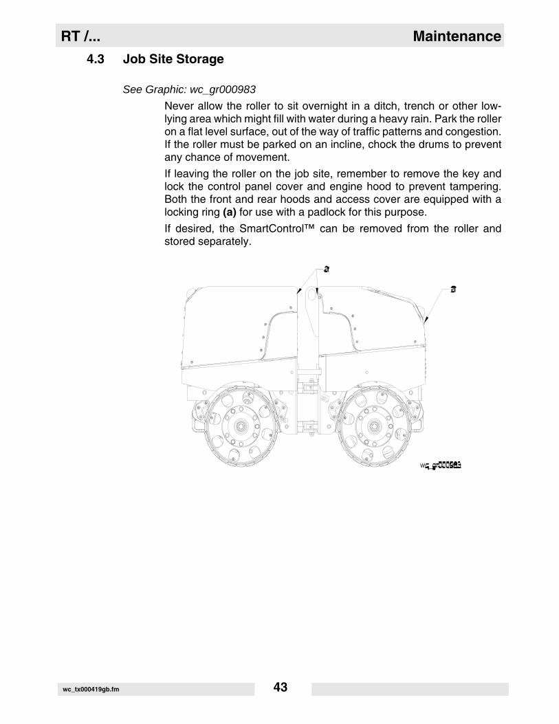
4.3 Job Site Storage
See Graphic: wc_gr000983
Never allow the roller to sit overnight in a ditch, trench or other low-lying area which might fill with water during a heavy rain. Park the rolleron a flat level surface, out of the way of traffic patterns and congestion.If the roller must be parked on an incline, chock the drums to preventany chance of movement.
If leaving the roller on the job site, remember to remove the key andlock the control panel cover and engine hood to prevent tampering.Both the front and rear hoods and access cover are equipped with alocking ring (a) for use with a padlock for this purpose.
If desired, the SmartControl™ can be removed from the roller andstored separately.
wc_tx000419gb.fm 43

Maintenance RT /...
4.4 Storage
If storing unit longer than 30 days, the following steps arerecommended:
4.4.1 Change the engine oil.
4.4.2 Clean or change air cleaner elements.
4.4.3 Drain any water that may have collected at the bottom of the fuel tank.Replace the fuel filter. Refill the tank with fresh No. 2 diesel fuel.
Note: Diesel fuel is subject to bacterial growth which can contaminatefuel lines. Allowing the tank to sit dry for a long period of time helpspromote such growth. The addition of a biocide to the fuel isrecommended to inhibit bacterial growth and protect the engine fuelsystem.
4.4.4 Store the unit indoors in a clean dry area. If the unit must be storedoutdoors, cover it.
4.5 New Machines
Perform initial oil and filter changes as listed below. Follow PeriodicMaintenance Schedules thereafter.
4.5.1 Change engine oil and replace oil filter after first 50 hours.
4.5.2 Replace hydraulic return line filter after first month or 100 hours.
wc_tx000419gb.fm 44

RT /... Maintenance
4.6 Periodic Maintenance Schedules
The chart below lists basic engine maintenance. Refer to the enginemanufacturer’s Operation Manual for additional information on enginemaintenance.
Roller Dailybefore
starting
Every100hrs.
Every500hrs.
Once A
Year
Every2
Years
Check hydraulic oil. Fill to correct level.
•
Clean control box / transmitter. •
Grease articulated joint. •
Grease steering cylinder. •
Grease hood hinges. •
Change oil in drive gearcase. •
Change hydraulic system return line filter.
•
Change hydraulic fluid. •
Change exciter oil. •
Lombardini Engine Dailybefore
starting
Every100hrs.
Every125hrs.
Every250hrs.
Every300hrs.
Every500 hrs.
Check engine oil. Fill to correct level.
Replace air filter if indicator light is on.
Check condition and tension on fan belt.
Clean engine head and cylinder fins.
Change oil in engine crankcase.
Replace engine oil filter.
Check and adjust fan belt.
Replace fuel filter cartridge.
Clean injectors and check injector pres-sure.
Replace fan belt.
Check valve clearance.
wc_tx000419gb.fm 45

Maintenance RT /...
4.7 Hydraulic Oil Requirements
Wacker recommends the use of a good petroleum-based, anti-wearhydraulic oil in the hydraulic system of this equipment. Good anti-wearhydraulic oils contain special additives to reduce oxidation, preventfoaming, and provide for good water separation.
When selecting hydraulic oil for your machine, be sure to specify anti-wear properties. Most hydraulic oil suppliers will provide assistance infinding the correct hydraulic oil for your machine.
Avoid mixing different brands and grades of hydraulic oils.
Most hydraulic oils are available in different viscosities.
The SAE number for an oil is used strictly to identify viscosity—it doesnot indicate the type of oil (engine, hydraulic, gear, etc.).
When selecting a hydraulic oil be sure it matches the specified SAEviscosity rating and is intended to be used as a hydraulic oil. SeeTechnical Data—Lubrication.
4.8 Hydraulic Oil Level
See Graphic: wc_gr000979
A hydraulic oil level sight gauge (c) is located on the hydraulic tankinside the rear section of the machine.
Check that the oil level is within 25 mm (one inch) of the top of the sightgauge. Add oil as required through the filter housing on top ofhydraulic tank.
If hydraulic oil continually needs to be added, inspect hoses andconnections for possible leaks. Repair hydraulic leaks immediately toprevent damage to hydraulic components.
wc_tx000419gb.fm 46

RT /... Maintenance
4.9 Changing Hydraulic Oil & Filter
See Graphic: wc_gr000979
Note: In the interests of environmental protection, place plasticsheeting and a container under the machine to collect the liquid whichdrains off. Dispose of this liquid properly.
To change hydraulic oil:
4.9.1 Remove drain plug from bottom of frame and allow hydraulic fluid todrain.
4.9.2 Clean filter housing cover. Remove cover from the filter housing andremove the filter element (a).
Be extremely careful to avoid dropping anything into the filter housingwhile cover is off.
4.9.3 Install drain plug.
4.9.4 Fill hydraulic tank through filter housing (b) using clean hydraulic fluid.
4.9.5 Install new filter element (a) as shown in illustration. Replace housingcover.
CAUTION
wc_tx000419gb.fm 47

Maintenance RT /...
4.10 Articulated Joint, Steering Cylinder, and Hood Hinges
See Graphic: wc_gr001665
Lubricate top and bottom bearing blocks (a), cylinder knuckles (b), andhood hinges (d) every 100 hours using a hand-held grease gun.Cylinder knuckles can be accessed through holes on side of machine(c).
Use Shell Alvania RL2 or an equivalent No. 2 general purpose grease.
4.11 Cleaning SmartControl™ Transmitter
The transmitter and switches are completely sealed to keep dust andmoisture out; however, contact with water should be kept to aminimum. Even a small amount of moisture can cause connectionsand contacts to corrode. Avoid immersing transmitter in water and donot clean using a pressure wash.
To clean the transmitter:
4.11.1 Wash off the transmitter using a damp cloth. Allow it to air dry.
4.11.2 To remove dirt and dust trapped around switches, use low-pressurecompressed air.
wc_tx000419gb.fm 48

RT /... Maintenance
4.12 Drive Gearcase
See Graphic: wc_gr000479
Any disassembly of the drive gearcase should be done on the oppositeside of machine from that shown in graphic wc_gr000479.
Change the oil in the drive gearcase once a year or every 500 hours ofoperation.
Note: In the interests of environmental protection, place plasticsheeting and a container under the machine to collect the liquid whichdrains off. Dispose of this liquid properly.
To change the oil:4.12.1 Remove drum from drivecase side of machine. On the front drum this
will be on the left side, on the rear drum it is the right side.
4.12.2 Open fill plug (c) for venting and then remove drain plug (b) frombottom of drum assembly.
4.12.3 Install drain plug and remove level plug (a) from gearcase.
4.12.4 Add SAE 10W30 oil through fill plug opening until oil flows out of levelplug opening, approximately 12.5 oz. (370 ml).
4.12.5 Replace plugs and install drum.
CAUTION
wc_tx000419gb.fm 49

Maintenance RT /...
4.13 Exciter Lubrication
See Graphic: wc_gr000975
The exciter is a sealed unit and under normal conditions should notrequire any periodic maintenance; however, an oil change once everytwo years is recommended to ensure bearing life.
Exciter maintenance should be done on the right front drum and leftrear drum only.
Changing the exciter oil requires special tools and should beperformed by an experienced mechanic.
Ref. Note
a Oil fill plug
b Oil drain plug
c Oil level plug (Maintain oil at this level.)
CAUTION
wc_tx000419gb.fm 50

RT /... Maintenance
4.14 Scrapers
See Graphic: wc_gr000976
Scraper bars are provided on all four drums to prevent dirt frombuilding up on the drum surfaces. These scrapers should be inspectedand adjusted as required to remove as much dirt from the drums aspossible.
To adjust a scraper:
Loosen the three screws (a) holding each scraper to the drum casting.Position the scraper 1/8–1/4" (3–6 mm) from the drum. Tighten screwsand run machine to check that the scraper does not rub against thedrum surface.
4.15 Shockmounts
See Graphic: wc_gr000978
Inspect the drum shockmounts (a) every 300 hours for cracking,splitting or tearing. Replace shockmounts as needed.
NOTICE: The shockmounts isolate the upper part of the machine fromthe heavy vibrations produced in the drums. Operating the machinewith damaged shockmounts for an extended period of time mayeventually damage other machine parts.
wc_tx000419gb.fm 51

Maintenance RT /...
4.16 Changing Drums
See Graphic: wc_gr000981
The drums can be changed to adjust the working width of the machine.Drums are available in two standard sizes that provide a working widthof 560 mm (22 in.) or 820 mm (32 in.).
To change drum:
4.16.1 Lock the articulated joint.
4.16.2 Remove scraper bars.
4.16.3 Use a screw jack, hoist or other type of lifting device to lift drums 25–50 mm (1–2 inches) off the ground. Lift only one end of the machine.Keep the other end in contact with the ground for stability.
4.16.4 Use a 22 mm wrench and remove the six screws which hold the drumto the drum support.
4.16.5 Remove the three plugs (a) covering the pusher holes.
4.16.6 Insert three of the mounting screws into the pusher holes and threadthem in evenly to push drum off.
4.16.7 Install new drum and fasten to support. Secure mounting screws witha medium-strength threadlocking adhesive.
4.16.8 Replace pusher hole plugs. Install the correct size scraper bars.
wc_tx000419gb.fm 52

RT /... Maintenance
4.17 Battery
The battery supplied on this machine is rated at 12V with 800 Amp coldcranking capacity. It features a sealed, ventless design, and isconstructed to resist vibration and provide longer service life.
DO NOT use automotive-type batteries on this machine. Automotive-type batteries are not designed to withstand the heavy vibrationproduced by this machine. The case on automotive-type batteriescould fail, causing battery acid to leak.
Inspect battery periodically. Keep battery terminals clean andconnections tight.
Maintain the battery at full charge to improve cold weather starting.
NOTICE: Observe the following to prevent serious damage to themachine’s electrical system:
• Never disconnect the battery with the machine running.
• Never attempt to run the machine without a battery.
• Never attempt to jump-start a machine.
• In the event that the machine has a dead battery, either replace the battery with a fully charged battery or charge the battery using an appropriate battery charger.
Explosion hazard. Batteries can emit explosive hydrogen gas. Keep allsparks and flames away from the battery. Do not short-circuit batteryposts. Do not touch the machine frame or the negative terminal of thebattery when working on the positive terminal.
CAUTION
WARNING
wc_tx000419gb.fm 53

Maintenance RT /...
4.18 Engine Oil System
See Graphic: wc_gr000971
Check the engine oil level daily. Add oil as required.
To check oil:
Place the machine on a level surface, remove the dipstick and checkthat the oil level is at the top mark. Add oil through the oil filler cap (a)on top of engine, checking occasionally with dipstick; DO NOT overfill.
Suggested oil grades:
Use only diesel engine oil API service rating CD or equivalent.
wc_tx000419gb.fm 54

RT /... Maintenance
4.19 Engine Oil and Filter
See Graphic: wc_gr000971
Change oil every 125 hours and oil filter (b) every 250 hours. On newmachines, change oil after first 50 hours of operation. Drain oil whileengine is still warm.
Note: In the interests of environmental protection, place plasticsheeting and a container under the machine to collect the liquid whichdrains off. Dispose of this liquid properly.
To change oil:
4.19.1 Remove oil filler cap (a) and oil drain plug (c). Drain oil into a suitablecontainer.
4.19.2 Reinstall the drain plug and tighten.
4.19.3 Remove and replace oil filter (b).
4.19.4 Remove oil filler cap (a) and fill engine crankcase with recommendedoil. See Technical Data for oil quantity and type.
4.19.5 Install oil filler cap.
wc_tx000419gb.fm 55

Maintenance RT / ...
4.20 Air Cleaner
See Graphic: wc_gr000968
Replace both air filter elements when the air filter warning lightilluminates. See Section Control Panel Features.
The air cleaner assembly contains a primary air filter element (a) anda secondary air filter element (f).
To replace the air filter elements:
4.20.1 Remove the end cover (b), then discard both filter elements.
4.20.2 Insert new air filter elements, then:
4.20.3 Re-install the end cover, making sure that the dust cap (c) is clean andis pointing downward.
Periodically, make sure the inlet pipe (d) is free from obstructions.
NOTICE: Check all connections and make sure they are snug. An airleak at the neck clamp or intake pipe can quickly lead to expensiveengine repairs.
• Make sure that the intake piping (e) is fully engaged over the neck of the filter to ensure a good seal.
• If the filter housing, neck, or inlet pipe are crushed or damaged, replace them immediately.
wc_gr005166
b
c
a
f
wc_tx000419gb.fm 56

RT /... Maintenance
4.21 Engine Fuel Delivery System Maintenance
Maintenance to the engine fuel delivery system should be performedby an experienced mechanic familiar with diesel engines. For detailedmaintenance procedures on the engine fuel system, refer to the enginemanual supplied with the machine at the time of shipment.
4.22 Fuel Filter
See Graphic: wc_gr000973
Change engine fuel filter every 300 hours of operation.
To change fuel filter:
4.22.1 Remove filter (a) from engine block.
4.22.2 Install new filter. If necessary, prime fuel lines as described in nextsection.
wc_tx000419gb.fm 57

Maintenance RT /...
4.23 Priming the Fuel System
See Graphic: wc_gr000973
If the fuel tank has been run completely dry or drained for service, it willbe necessary to manually prime the fuel system.
To prime the fuel system:
4.23.1 Turn both the key switch on the machine, and the on-off switch oncontrol box, on. This will open the fuel valve.
4.23.2 Loosen the bleed screw on the fuel filter and pump the lever on the fuelpump (b) until fuel flows freely from the bleed screw. Tighten the bleedscrew.
4.23.3 Repeat this procedure for the fuel line bleed screw (c).
4.24 Engine Coolant
Check the coolant level of the radiator daily while the engine is coldThe coolant level should be at the cold level mark (lower line) on theoverflow bottle. Add coolant in a 50% water/50% glycol mixture ifrequired.
NEVER remove the radiator cap or drain plug while the engine is hot!Pressurized coolant can cause serious burns.
If it is necessary to open the radiator, only do so with the engine off,and only when coolant is cool enough to touch with bare hands. Slowlyloosen cap to relieve pressure first, before removing it completely.
WARNING
wc_tx000419gb.fm 58

RT /... Maintenance
4.25 Valve Clearances
See Graphic: wc_gr002366
Check and adjust valve clearance every 500 hours. Set clearance withengine cold. Replace the valve/rocker arm cover gasket whenchecking the valve clearances. Refer to the engine manufacturer’sservice manual for detailed information.
To adjust valve clearances:
4.25.1 Remove valve/rocker arm cover
4.25.2 Bring each cylinder piston to top dead center on the compressionstroke and set clearance.
4.25.3 Valve clearance (A): 0.20mm (0.008 in.).
Valve clearance (B): 0.15mm (0.006 in.).
4.25.4 Clean gasket material from cylinder head.
4.25.5 Place a small bead of RTV Silicone on cylinder head to secure ends ofnew gasket. Gently place gasket on cylinder head.
4.25.6 Replace valve/rocker arm cover. Torque bolts to 9 Nm (7 ft.lbs.).
wc gr002366
wc_tx000419gb.fm 59

Maintenance RT /...
4.26 Adjusting Engine Fan Belt
See Graphic: wc_gr002377
4.26.1 Remove the hydraulic oil cooler. See Section Replacing Hydraulic OilCooler.
4.26.2 Remove radiator and shroud. See Section Replacing Radiator andShroud.
4.26.3 Remove the four screws (a) securing the fan to the engine and removethe fan.
4.26.4 Remove the outer pulley plate (b).
4.26.5 Insert the appropriate amount of shims (c) to give you the requiredtension on the belt. The fewer the number of shims, the tighter the beltwill be. Approximately 6–12 mm (1/4–1/2 in.) deflection isrecommended.
4.26.6 Place unused shims between outer pulley plate and fan whenreinstalling the fan. Secure the fan to the engine with the four screws(a).
wc_tx000419gb.fm 60

RT /... Maintenance
wc_tx000419gb.fm 61

Maintenance RT /...
4.27 Basic Troubleshooting
Problem / Symptom Reason / Remedy
ENGINE DOES NOT START • Fuel tank empty. Fill with No. 2 diesel fuel and prime fuel lines.
• Wrong type of fuel.• Old fuel. Drain tank, change fuel filter and fill with
fresh fuel.• Fuel system not primed.• Fuel filter restricted or plugged. Replace filter.• Battery connections loose or corroded. Battery dead.• Engine oil level too low.• Air cleaner element plugged.• Starter motor defective.• Starter button on control box or transmitter defective.• Fuel valve solenoids on engine inoperative.• Starter relay inoperative.• Electrical connections loose or broken.• Machine out of infrared signal range.
ENGINE STOPS BY ITSELF • Fuel tank empty.• Fuel filter plugged.• Fuel lines broken or loose.• Machine out of infra-red range.
NO VIBRATION • Machine in high speed travel mode.• Defective switch or poor connection in control box or
transmitter.• Solenoid on vibration valve inoperative.• Exciter assembly damaged.• Exciter motor coupling damaged.• Exciter motor damaged.• Exciter pump damaged.
NO TRAVEL or TRAVEL ONLY IN ONE DIRECTION
• Defective switch or poor connection in control box or transmitter.
• Solenoid on travel valve inoperative.• Drive gearcase assembly damaged.• Loose, broken or corroded wire connections.• Drive motor damaged.• Drive pump damaged.
wc_tx000419gb.fm 62

RT /... Maintenance
NO HIGH SPEED TRAVEL • Defective switch or poor connection in control box or transmitter.
• Solenoid on manifold inoperative.• Loose, broken or corroded wire connections.• Exciter pump worn or damaged.• Vibration is turned on.
NO STEERING • Defective switch or poor connection in control box or transmitter.
• Solenoid on steering valve inoperative.• Loose, broken or corroded wire connections.• Steering cylinder damaged.• Locking bar is engaged.
Problem / Symptom Reason / Remedy
wc_tx000419gb.fm 63

RT /... Technical Data
wc_td000077gb.fm 64
5. Technical Data
5.1 Engine
Engine Power Rating
Net power rating per ISO 3046. Actual power output may vary due to conditionsof specific use.
Item No.:
RT 56-SC (0009026) RT 82-SC (0009025) Revisions 108 and
lower RT 56-SC (0620366)
RT 56-SC (0009026) RT 82-SC (0009025)RT 82-SC (0620480)RT 82-SC (0620481)RT 82-SC (0620482)Revisions 109 and
higherRT 82-SC (0620324)RT 82-SC (0620365)
RT 82-STC (0620397)
Engine
Engine Type 3-cylinder, 4-cycle, liquid-cooled, diesel engine
Engine Make Lombardini
Engine Model LDW 903 LDW 1003
Rated Power kW (Hp) 15.6 (21.2) @ 3600 rpm
15.5 (20.8) @ 2600 rpm
Alternator Amp / V 23.8 / 16.5 @ 2600 rpm
Engine Speed - full load rpm 2600
Engine Speed - idle rpm 1300
Valve Clearance (cold) intake: exhaust:
mm (in.) 0.15 (0.006)0.20 (0.008)
Air Cleaner type Dry pleated paper elements
Battery V / CCA 12V - Sealed / 800
Fuel type No. 2 Diesel
Fuel Tank Capacity l (gal.) 24 (6.3)
Fuel Consumption l (gal.)/hr. 5.64 (1.49)
Radiator Capacity l (gal.) 4.75 (1.25)

RT /... Technical Data
5.2 Roller
Item No:
RT 56-SC00090260620366
RT 82-SC00090250620365062048006204810620482
RT 82-STC0620397
RT 82-SC0620324
Roller
Operating Weight kg (lb.) 1391 (3068) 1473 (3247) 1434 (3161)
Area Capacity m² (ft²) / hr. 668 (7260) 972 (10560) 972 (10560)
Inside Turning Radius m (in.) 1.9 (73) 1.6 (63) 1.6 (63)
Travel Speed m (ft.)/min. 41.66 (136.7) High20 (65.6) Low
37.5 (123.2)19 (62.4)
Vibration Frequency Hz (vpm) 41.7 (2500)
Gradeability with Vibration
% 50 ---
Gradeability w/o Vibration
% 45 30
wc_td000077gb.fm 65

Technical Data RT /...
5.3 Lubrication
5.4 Sound and Vibration Measurements
Products are tested for sound pressure level in accordance with ENISO 11204. Sound power level is tested in accordance with EuropeanDirective 2000/14/EC - Noise Emission in the Environment byEquipment for use outdoors.
The sound pressure level at operator's location (LpA) = 83 dB(A).
The guaranteed sound power level (LWA) = 109 dB(A).
Because this machine is operated using remote control the operator isnot exposed to vibration.
Item No:
RT 56-SC00090260620366
RT 82-SC00090250620365062048006204810620482
RT 82-STC0620397
RT 82-SC0620324
Lubrication
Engine Crankcase typel (qt.)
SAE 15W40 Class CD rated2.5 (2.5)
Hydraulic System typel (gal)
Premium grade, anti-wear hydraulic fluid SAE 10W3030 (8)
Exciter typeml (oz.)
SAE 10W30950 (32)
Drum Drive Gearcase typeml (oz.)
SAE 10W30370 (12.5)
Articulated Joint typeqty.
Shell Alvania RL2 Greaseas required
Steering Cylinder typeqty.
Shell Alvania RL2 Greaseas required
Radiator typeqty. %
Water / Glycol50 / 50
wc_td000077gb.fm 66

RT /... Technical Data
5.5 Dimensions—0009025, 0009026, 0620365, 0620366, 0620397,0620480, 0620481, 0620482
mm(in.)
5.6 Dimensions—0620324
mm(in.)
wc_td000077gb.fm 67

Technical Data RT /...
5.7 Wiring Schematic—Machine Rev. 121 and lower
wc_gr004253
wc_td000077gb.fm 68

RT /... Technical Data
PRES
SURE
N.C.
(2)�PU
RPLE
=GLO
W�P
LUG�
TIME
R(2)�PU
RPLE
=GLO
W�P
LUG�
TIME
R(3)�PINK=HIGH�
TEMP
�SIGNAL
(3)�PINK=HIGH�
TEMP
�SIGNAL
TEMP
�SWITCH
TEMP
�SWITCH
REST
RICT
ION
N.O.
GROUND
INT.
GROUND
FUEL
SOLE
NOID
N.C.
GLOW
�PLU
GSGL
OW�P
LUGS
THRO
TTLE
SOLE
NOID
LEVEL
SWITCH
PINK/YELLOW
�(14
�GA)
PINK/YELLOW
�(14
�GA)
BROWN
TAN/GREEN
CONNECTOR
2�PIN�
METRIPACK�
280
2�PIN�
METRIPACK�
280
P/N�
1204
�0753
P/N�
1204
�0753
LOW
�OIL
LOW
�OIL
(2)�PURPLE (2)�PURPLE
CONNECTOR
4�PIN�
DEUTSCH
4�PIN�
DEUTSCH
DT06-4S-P012
BLACK/WHITE
(1)�RED (1)�RED
(4)�BLACK (4)�BLACK
(3)�PINK (3)�PINK
B+PINK/TAN
TAN/BLUE
BROWN
DUAL
�FUN
CTION
DUAL
�FUN
CTION
BROWN
GREEN/PINK
(2)�WHITE (2)�WHITE SIG
CONN
ECTO
R3�PIN�
DEUTSCH
3�PIN�
DEUTSCH
DT06-3S-P012
TAN/WHITE
HIGH
�AIR
HIGH
�AIR
CONNECTOR
2�PIN�
METRIPACK�
280
2�PIN�
METRIPACK�
280
P/N�
1204
�0753
P/N�
1204
�0753
BSIGN
AL
A12VDC
CCONN
ECTO
R3�PIN�
DEUTSCH
3�PIN�
DEUTSCH
DT06-3S-EE01
WITH�
SHRINK
�BOOT
WITH�
SHRINK
�BOOT
SHIELD
ING
ANY�
COLO
RAN
Y�CO
LOR
ANY�
COLO
RAN
Y�CO
LOR
CONN
ECTO
R4�PIN�
DEUTSCH
4�PIN�
DEUTSCH
DT06-4S-P012
PINK
1 43GR
OUND
2BR
OWN
GREE
N/TA
N
GREEN/LT
�BLUE
GREEN/LT
�BLUE
GREEN/TAN
PINK/WHITE
GREE
N/BR
OWN
20�AMP
�FUSE
20�AMP
�FUSE
(1)�PURPLE (1)�PURPLE
CONNECTOR2�PIN�DEUTSCH 2�PIN�DEUTSCHDT06-2S-P012
PINK/WHITE
14�G
AGE
14�G
AGE
ALT.
RED
YELLOWYELLOW
YELLOWYELLOW
CONNECTORS2�PIN�DEUTSCH 2�PIN�DEUTSCHDT04-2P
(2)�GREEN (2)�GREENWHITE
RED/BLUE
�(14
�GA)
RED/BLUE
�(14
�GA)
RED/
GREE
N
SOL
STAR
TER
RED�
(14�
GA)
RED�
(14�
GA)
RED�
(BATTERY
�CABLE)
RED�
(BATTERY
�CABLE)
RED/PINK
�(14
�GA)
RED/PINK
�(14
�GA)
CL
BG
G
VOL
TAGE
REGU
LAOR
"L"�TO
�GRO
UND�
WHE
N"L"�TO
�GRO
UND�
WHE
NCHARGING
�FAULT
CHARGING
�FAULT
PINK
/GRA
YGREEN/LT
�BLUE
GREEN/LT
�BLUE
TAN
BLAC
K/YE
LOW
PINK
/BLA
CKTA
N/GR
EEN
PINK
��(14�
GA)
PINK
��(14�
GA)
BLAC
K/WHITE
BROW
NTA
N/WHITE
GREE
N/PINK
TAN/BLUE
21PO
WER
�ON�
(OUT
)PO
WER
�ON�
(OUT
)
54FU
EL�(IN)
FUEL
�(IN)
6
STAR
T�(IN)
STAR
T�(IN)
THRO
TTLE
�(IN)
THRO
TTLE
�(IN)
3
KEY�
SWITCH
�(IN)
KEY�
SWITCH
�(IN)
8 9
GROU
ND1211107CO
NNECTOR�
(BLACK)
CONNECTOR�
(BLACK)
12�PIN
�DEUTSCH
12�PIN
�DEUTSCH
DMT06-
12SB
50�AMP�FUSE 50�AMP�FUSE
SOLENOID�EXCITATION SOLENOID�EXCITATIONRED/BLACK�(10�GA) RED/BLACK�(10�GA)
RED/WHITE�(10�GA) RED/WHITE�(10�GA)
CONT
ROL�
MODU
LECO
NTRO
L�MO
DULE
BLOC
K�TE
MP�S
ENSO
R�(IN)
BLOC
K�TE
MP�S
ENSO
R�(IN)
OIL�
PRES
SURE
�SEN
SOR�
(IN)
OIL�
PRES
SURE
�SEN
SOR�
(IN)
RED�
LED�
LIGH
T�RING
RED�
LED�
LIGH
T�RING
AIR�
FILT
ER�S
ENSO
R�(IN)
AIR�
FILT
ER�S
ENSO
R�(IN)
COOL
ANT�
LEVEL
�SEN
SOR�
(IN)
COOL
ANT�
LEVEL
�SEN
SOR�
(IN)
WAT
ER�T
EMP�
SENS
OR�(IN)
WAT
ER�T
EMP�
SENS
OR�(IN)
BLACK�(14�GA) BLACK�(14�GA)
RED�(10�GAGE) RED�(10�GAGE)
(NOT
�USE
D)(NOT
�USE
D)
RED�
SIGN
ALRE
D�SIGN
ALAM
BER�
SIGN
ALAM
BER�
SIGN
AL
FRON
T�LIGH
T�RING
FRON
T�LIGH
T�RING
FRON
T�RE
CEIV
ING�
EYE
FRON
T�RE
CEIV
ING�
EYE
GROU
ND/S
HIEL
D
P85
87
8630
BROWN
PINK/YELLOW�(14�GA) PINK/YELLOW�(14�GA)RED/BLUE�(14�GA) RED/BLUE�(14�GA)
PINK/GRAY
G
3086
8785
3087
PINK
BROWN
BROWN
PINK/GREEN
T
8685
BROWN
BROWN
RED/BLACK
PINK/BLUE
PINK/GREEN
RED/WHITE
(3)�BLACK (3)�BLACK GRN
PINK\TAN
BROWN
TAN/YELLOW
INT.
PINK�(10�GA) PINK�(10�GA)
BROWNPINK/PURPLE�(16�GA) PINK/PURPLE�(16�GA)PINK/GREEN�(16�GA) PINK/GREEN�(16�GA) P
GH
(3)�BLACK (3)�BLACK(1)�RED (1)�RED(2)�WHITE (2)�WHITE
GREE
N/RE
DGREEN/ORANGE
GREEN/PURPLE
GREE
N/WHITE
GREEN/YELLOW
PINK
/GRE
EN
GREE
N/BL
ACK
TAN/
YELL
OWPINK/RED
BLACK�
(14�
GA)
BLACK�
(14�
GA)
PINK/PURPLE�
(16�
GA)
PINK/PURPLE�
(16�
GA)
1 32 6 754 8 9 10 1211 CONNECTOR�
(GRAY)
CONNECTOR�
(GRAY)
12�PIN
�DEUTSCH
12�PIN
�DEUTSCH
DMT06-
12SA
BROW
N
BROW
NBR
OWN
BROW
N
BLAC
K
ROLL
�OVER
�LAM
P�(OUT
)RO
LL�O
VER
�LAM
P�(OUT
)GL
OW�P
LUG�
LAMP
�(OU
T)GL
OW�P
LUG�
LAMP
�(OU
T)
AIR�
FILT
ER�L
AMP�
(OUT
)AIR�
FILT
ER�L
AMP�
(OUT
)
THRO
TTLE
�PUL
L�(OUT
)TH
ROTT
LE�P
ULL�
(OUT
)TH
ROTT
LE�H
OLD�
(OUT
)TH
ROTT
LE�H
OLD�
(OUT
)
FUEL
�SOL
ENOID�
(OUT
)FU
EL�S
OLEN
OID�
(OUT
)
WAT
ER�T
EMP�
LAMP
�(OU
T)WAT
ER�T
EMP�
LAMP
�(OU
T)
HOUR
�MET
ER�E
NABL
E�(OUT
)HO
UR�M
ETER
�ENA
BLE�
(OUT
)CO
OLAN
T�LE
VEL
�LAM
P�(OUT
)CO
OLAN
T�LE
VEL
�LAM
P�(OUT
)
GLOW
�PLU
G�RE
LAY�
(OUT
)GL
OW�P
LUG�
RELA
Y�(OUT
)ST
ARTE
R�SO
LENO
ID�(OU
T)ST
ARTE
R�SO
LENO
ID�(OU
T)
OIL�
PRES
SURE
�LAM
P�(OUT
)OIL�
PRES
SURE
�LAM
P�(OUT
)
BROW
NBR
OWN
BROW
N
ENGINE
GROU
ND
BROW
N
CONN
ECTO
R3�PIN�
DEUTSCH
3�PIN�
DEUTSCH
DT06-3S-P012
GREE
N
COOL
ANT
PINK/BROWN (1)�RED (1)�RED B+
1
3
4
5
wc_gr004295
2
wc_td000077gb.fm 69

Technical Data RT /...
5.8 Wiring Schematic—Machine Rev. 122 and higher
HYDR
AULIC
VAL
VES
HYDR
AULIC
VAL
VES
BRAKE
BRAKE
STEE
RING
-LEF
TST
EERING
-LEF
TST
EERING
-RIGHT
STEE
RING
-RIGHT
FORW
ARD
FORW
ARD
VIBRA
TION
-HIGH
VIBRA
TION
-HIGH
VIBRA
TION
-LOW
VIBRA
TION
-LOW
HIGH
SPE
EDHIGH
SPE
ED
REVERSE
REVERSE
MANIFOLD GROUNDED
MANIFOLD GROUNDED
TO BATTERY DISCONECT
TO BATTERY DISCONECT
SWITCH
SWITCH
REAR
REC
EIVING
EYE
REAR
REC
EIVING
EYE
CONN
ECTO
RSCO
NNEC
TORS
DIN
4365
0DIN
4365
0
CONNECTOR
CONNECTOR
3 PIN
DEUT
SCH
3 PIN
DEUT
SCH
DT06-3S-EE01
DT06-3S-EE01
WITH SHRINK BOOT
WITH SHRINK BOOT
12VDC
12VDC
SIGNAL
SIGNAL
GROU
ND/S
HIEL
DGR
OUND
/SHIEL
D
REAR
LIGHT
RING
REAR
LIGHT
RING
AMBER SIGNAL
AMBER SIGNAL
GROUND
GROUND
(NOT
USE
D)(NOT
USE
D)
RED
SIGN
ALRE
D SIGN
AL
ASH
IELD
ING
SHIELD
ING
BAN
Y CO
LOR
ANY
COLO
RC 1 432
BROW
NBR
OWN
GREE
N/BL
UEGR
EEN/
BLUE
GREE
N/LT
BLU
EGR
EEN/
LT B
LUE 5121243
CONNECTOR
CONNECTOR
12 P
IN D
EUTS
CH12 P
IN D
EUTS
CHDT
06-12S
B-P012
DT06-12S
B-P012
WHITE
WHITE
PINK
/BLU
EPINK
/BLU
E
CONNECTOR
CONNECTOR
4 PIN
DEUT
SCH
4 PIN
DEUT
SCH
DT06-4S-P012
DT06-4S-P012 (NOT
USE
D)(NOT
USE
D)(NOT
USE
D)(NOT
USE
D)
DISP
LAY
MODU
LEDISP
LAY
MODU
LE
ALTERNATOR LAMP (IN)
ALTERNATOR LAMP (IN)
SWITCH
ED P
OWER
ON
(IN)
SWITCH
ED P
OWER
ON
(IN)
ANY
COLO
RAN
Y CO
LOR
BLAC
KBL
ACK
BLAC
KBL
ACK
BLAC
KBL
ACK
BLAC
KBL
ACK
BLAC
KBL
ACK
BLAC
KBL
ACK
BLAC
KBL
ACK
4B4B3B3B 7B7B6B6B5B5B2B2B1B1B
DECO
DER
MODU
LEDE
CODE
R MO
DULE
BRAK
EBR
AKE
FORW
ARD
FORW
ARD
STEE
RING
-LEF
TST
EERING
-LEF
TST
EERING
-RIGHT
STEE
RING
-RIGHT
VIBRA
TION
-HIGH
VIBRA
TION
-HIGH
VIBRA
TION
-LOW
VIBRA
TION
-LOW
HIGH
SPE
EDHIGH
SPE
ED
BLAC
KBL
ACK
8B8B
BROW
NBROW
N
BLAC
KBL
ACK
BLAC
KBL
ACK
BLAC
KBL
ACK
11B
11B
10B
10B
12B
12B 1A1A9B9B 2A2A 6A6A 7A7A5A5A 8A8A 9A9A
TAN
TAN
4A4A3A3A
REVER
SERE
VER
SEGR
OUND
GROU
ND
GROU
NDGR
OUND
GROU
NDGR
OUND
GROU
NDGR
OUND
GROU
NDGR
OUND
12VDC
INP
UT12VDC
INP
UT
CONT
ROL
LIGH
TCO
NTRO
L LIGH
TFR
ONT
EYE
12VDC
FRON
T EY
E 12VDC
CONT
ROL
LIGH
TCO
NTRO
L LIGH
T
FRON
T EY
E GR
OUND
FRON
T EY
E GR
OUND
FRON
T EY
E DA
TAFR
ONT
EYE
DATA
FUEL
VAL
VES
FUEL
VAL
VESST
ARTE
RST
ARTE
R
BLAC
KBL
ACK
5C5C3C3C 4C4C 7C7C6C6C2C2C1C1CGROUND
GROUND
012
012 W
HITE
WHITE
BLACK
BLACK
321 5 6 74
CONNECTOR (BROWN)
CONNECTOR (BROWN)
12 P
IN D
EUTS
CH12 P
IN D
EUTS
CHDT
06-12S
D-CE
04DT
06-12S
D-CE
04WITH SHRINK BOOT
WITH SHRINK BOOT 8C8C 11
C11C
10C
10C
12C
12C
9C9C8 9
2 31
12VDC OUTPUT
12VDC OUTPUT
DECO
DER
HAS
10 S
ECON
DDE
CODE
R HA
S 10 S
ECON
DSW
ITCH
OVER
DEL
AY F
ORSW
ITCH
OVER
DEL
AY F
OREX
CITE
R OU
TPUT
SEX
CITE
R OU
TPUT
S
10A
10A
12A
12A
11A
11A
REAR
EYE
DAT
ARE
AR E
YE D
ATA
REAR
EYE
GRO
UND
REAR
EYE
GRO
UND
REAR
EYE
12V
DCRE
AR E
YE 12V
DC
CONNECTOR (GREEN)
CONNECTOR (GREEN)
12 P
IN D
EUTS
CH12 P
IN D
EUTS
CHDT
06-12S
C-CE
04DT
06-12S
C-CE
04WITH SHRINK BOOT
WITH SHRINK BOOT
CONNECTOR (GRAY)
CONNECTOR (GRAY)
12 P
IN D
EUTS
CH12 P
IN D
EUTS
CHDT
06-12S
A-E008
DT06-12S
A-E008
WITH SHRINK BOOT
WITH SHRINK BOOT
GREE
N/BL
UEGR
EEN/
BLUE
ANY COLOR
ANY COLOR
GREE
N/BR
OWN
GREE
N/BR
OWN
BLACK/YELLOW
BLACK/YELLOW
PINK
/YEL
LOW (14 G
A)PINK
/YEL
LOW (14 G
A)
ANY COLOR
ANY COLOR
ANY COLOR
ANY COLOR
ANY COLOR
ANY COLOR
SHIELDING
SHIELDING
SHIELDING
SHIELDING
8 7926111111010
GROUND
GROUND
BROW
NBR
OWN
GREE
N/RE
DGR
EEN/
RED
GREE
N/OR
ANGE
GREE
N/OR
ANGE
GREE
N/BL
ACK
GREE
N/BL
ACK
GREE
N/WHITE
GREE
N/WHITE
GREE
N/PU
RPLE
GREE
N/PU
RPLE
GREE
N/YE
LLOW
GREE
N/YE
LLOW
OIL
PRES
SURE
LAM
P (IN)
OIL
PRES
SURE
LAM
P (IN)
AIR FILTER LAMP (IN)
AIR FILTER LAMP (IN)
ROLL
OVER
LAM
P (IN)
ROLL
OVER
LAM
P (IN)
GLOW
PLU
G LA
MP (IN)
GLOW
PLU
G LA
MP (IN)
LOW C
OOLA
NT L
AMP
(IN)
LOW C
OOLA
NT L
AMP
(IN)
HOUR
MET
ER E
NABL
E (IN)
HOUR
MET
ER E
NABL
E (IN)
WATER TEMP LAMP (IN)
WATER TEMP LAMP (IN)
GREE
NGR
EEN
-+ BA
TTER
YBA
TTER
Y
REAR
FRA
ME G
ROUN
D.RE
AR F
RAME
GRO
UND.
ATTA
CH T
O HY
D VAL
VE.
ATTA
CH T
O HY
D VAL
VE.
(NOT
USE
D)(NOT
USE
D)2
GROUND
GROUND
4(NOT
USE
D)(NOT
USE
D)31
20 AMP FUSE 20 AMP FUSE
RED/YELLOW (14 GA) RED/YELLOW (14 GA)
RED/
GREE
NRE
D/GR
EEN
CONNECTOR
CONNECTOR
4 PIN
DEUT
SCH
4 PIN
DEUT
SCH
DT06-4S-P012
DT06-4S-P012
CONNECTOR
CONNECTOR
4 PIN
METR
IPAC
K 28
04
PIN
METR
IPAC
K 28
0PA
CKAR
D #1205
2856
PACK
ARD
#1205
2856
BROW
NBR
OWN
FRAM
E GR
OUND
WIRE
FRAM
E GR
OUND
WIRE
A
(NOT
USE
D)(NOT
USE
D)C D
(NOT
USE
D)(NOT
USE
D)B 21
PINK/GRAY PINK/GRAY
CONNECTOR
CONNECTOR
10 PIN CARLINGSW
ITCH
10 PIN CARLINGSW
ITCH
VCI
VCI
RED/
YELL
OW (14 G
A)RE
D/YE
LLOW
(14 G
A)
PINK
(14 G
A)PINK
(14 G
A)
PINK
/BLA
CKPINK
/BLA
CKPINK
/GRA
YPINK
/GRA
Y
MULT
I PIN
TRAILE
R PL
UGMU
LTI PIN
TRAILE
R PL
UG
12VDC
INP
UT12VDC
INP
UTGR
OUND
GROU
ND
KEY
SWITCH
KEY
SWITCH
12VDC
SWITCH
ED O
UTPU
T12VDC
SWITCH
ED O
UTPU
T
12VDC
INP
UT12VDC
INP
UT
12VDC
INP
UT12VDC
INP
UT12VDC
SWITCH
ED O
UTPU
T12VDC
SWITCH
ED O
UTPU
T
THRO
TTLE
SWITCH
THRO
TTLE
SWITCH
CHAR
GE P
ORT
WITH
CHAR
GE P
ORT
WITH
1.85
AMP
FUSE
1.85
AMP
FUSE
12VDC
-1.85
AMP
FUSE
12VDC
-1.85
AMP
FUSE
2
34
5
1
wc_gr004296
wc_td000077gb.fm 70

RT /... Technical Data
PINK
/YEL
LOW (14 G
A)
BROWN
TAN/GREEN
CONN
ECTO
R2
PIN
METR
IPAC
K 28
0P/N 1204 0753
LOW OIL
PRESSURE
N.C.
(2) PURPLE
CONN
ECTO
R4 PIN DEUTSCH
DT06-4
S-P012
BLACK/WHITE
(1) RED
(4) BLACK
(3) PINK
B+PINK/TAN
TAN/BLUE
BROWN
(2) PU
RPLE
=GLO
W P
LUG
TIME
R(3) PINK=HIGH TEMP SIGNAL
DUAL FUNCTION
TEMP SWITCH
BROWN
GREEN/PINK
(2) WHITE SIG
CONN
ECTO
R3 PIN DEUTSCH
DT06-3
S-P012
TAN/WHITE
HIGH AIR
RESTRICTION
N.O.
CONN
ECTO
R2
PIN
METR
IPAC
K 28
0P/N 1204 0753
BSIGNAL
A12VDC
CCONN
ECTO
R3 PIN DEUTSCH
DT06-3
S-EE
01WITH
SHRINK
BOO
T
SHIELD
ING
ANY
COLO
R
ANY
COLO
R
CONN
ECTO
R4 PIN DEUTSCH
DT06-4
S-P012
PINK
1 43GROUND
2BR
OWN
GREE
N/TA
N
GREEN/LT BLUE
GREEN/TAN
PINK/WHITE
GREE
N/BR
OWN
20 A
MP F
USE
(1) PURPLE
CONNECTOR2 PIN DEUTSCHDT06-2S-P012
PINK/WHITE
14 GAGE
ALT.
RED
YELLOWYELLOW
YELLOWYELLOW
CONNECTORS2 PIN DEUTSCHDT04-2P
(2) GREENWHITE
RED/
BLUE
(14 G
A)
RED/
GREE
N
SOL
STARTER
RED
(14
GA)
RED
(BAT
TERY
CAB
LE)
RED/
PINK
(14 G
A)
CL
BG
G
VOLTAGE
REGULAOR
"L" TO
GRO
UND
WHE
NCH
ARGING
FAU
LT
PINK
/GRA
YGREEN/LT BLUE
TAN
BLAC
K/YE
LOW
PINK
/BLA
CKTA
N/GR
EEN
PINK (14 GA)
BLAC
K/WHITE
BROW
NTA
N/WHITE
GREE
N/PINK
TAN/
BLUE
21POWER ON (OUT)
54FUEL (IN)
6
START (IN)
THROTTLE (IN)
3
KEY SW
ITCH (IN)
8 9
GROUND
1211107CONNECTOR (BLACK)
12 P
IN D
EUTS
CHDM
T06-
12SB
50 AMP FUSE
SOLENOID EXCITATIONRED/BLACK (10 GA)
RED/WHITE (10 GA)
CONTROL MODULE
BLOCK TEMP SENSOR (IN)
OIL PRESSURE SENSOR (IN)
RED LED LIGHT RING
AIR FILTER SENSOR (IN)
COOLANT LEVEL SENSOR (IN)
WATER TEMP SENSOR (IN)
BLACK (14 GA)
RED (10 GAGE)
(NOT USED)
RED SIGNAL
AMBER SIGNAL
FRONT LIGHT RING
FRONT RECEIVING EYE
GROUND/SHIELD
P85
87
8630
BROWN
PINK/YELLOW (14 GA)RED/BLUE (14 GA)
PINK/GRAY
G
3086
8785
3087
PINK
BROWN
BROWN
PINK/GREEN
T
8685
BROWN
BROWN
RED/BLACK
PINK/BLUE
PINK/GREEN
RED/WHITE
(3) BLACK GRN
PINK\TAN
BROWN
TAN/YELLOW
INT.
GROU
NDINT.
GROU
NDFUEL
SOLENOID
NC
N.C.
PINK (10 GA)
BROWNPINK/PURPLE (16 GA)PINK/GREEN (16 GA)
GLOW
PLUGS
THROTTLE
SOLENOIDP
GH
(3) BLACK(1) RED(2) WHITE
GREE
N/RE
DGR
EEN/
ORAN
GE
GREE
N/PU
RPLE
GREE
N/WHITE
GREE
N/YE
LLOW
PINK
/GRE
EN
GREE
N/BL
ACK
TAN/
YELL
OWPINK
/RED
BLACK (14 GA)
PINK
/PUR
PLE
(16
GA)
1 32 6 754 8 9 10 1211 CONN
ECTO
R (GRA
Y)12 P
IN D
EUTS
CHDM
T06-
12SA
BROW
N
BROW
NBR
OWN
BROW
N
BLAC
K
ROLL OVER LAMP (OUT)
GLOW
PLUG LAMP (OUT)
AIR FILTER LAMP (OUT)
THROTTLE PULL (OUT)
THROTTLE HOLD (OUT)
FUEL SOLENOID (OUT)
WATER TEMP LAMP (OUT)
HOUR METER ENABLE (OUT)
COOLANT LEVEL LAMP (OUT)
GLOW
PLUG RELAY (OUT)
STARTER SOLENOID (OUT)
OIL PRESSURE LAMP (OUT)
BROW
NBR
OWN
BROW
N
ENGINE
GROUND
BROW
N
CONN
ECTO
R3 PIN DEUTSCH
DT06-3
S-P012
GREE
N
COOLANT
LEVEL
SWITCHPINK/BROWN (1) RED B+
1
3
4
5
wc_gr004295
2
wc_td000077gb.fm 71


KE40246P1 6/9/05 3:14 PM Page 1
NOTICE OF COPYRIGHT PROTECTIONAEM Safety Manuals are protected as a copyrighted work withownership duly registered with the Copyright Office,Washington,D.C.Any reproduction, translation, decompiling or other use of anAEM Safety Manual, or portion thereof, or the creation of deriv-
ative works based on an AEM Safety Manual,without the prior writ-ten approval of AEM, is expressly prohibited. Copyright infringe-ment can result in civil and criminal sanctions, damages and otherpenalties being imposed.
Copyright © 1978 AEM (Association of Equipment Manufacturers)Former Copyright © CIMA (Construction Industry Manufacturer Association)
Revised 6/02, 9/04
SAFETY ALERT SYMBOLThis Safety Alert Symbol meansATTENTION is involved!
The Safety Alert Symbol identifies important safetymessages on machines, safety signs, in manuals, orelsewhere.When you see this symbol, be alert tothe possibility of personal injury or death. Followthe instructions in the safety message.
Why is SAFETY important to YOU?
3 BIG REASONS:• Accidents KILL or DISABLE• Accidents COST• Accidents CAN BE AVOIDED
KE40246P2 6/9/05 3:16 PM Page i

WORD OF EXPLANATION................................................................................ 2
FOREWORD.......................................................................................................... 4
A WORD TO THE USER ...................................................................................... 5
FOLLOW A SAFETY PROGRAM ...................................................................... 6
PREPARE FOR SAFE OPERATION.................................................................... 9
START SAFELY....................................................................................................15
WORK SAFELY .................................................................................................. 18
PARK & SHUTDOWN SAFELY ...................................................................... 23
LOAD & UNLOAD MACHINE SAFELY ........................................................ 25
TRANSPORTING SAFELY .............................................................................. 26
PERFORM MAINTENANCE SAFELY ............................................................ 28
SPECIAL OPERATING AND MAINTENANCE PRECAUTIONS................ 43
TEST YOUR KNOWLEDGE ............................................................................ 47
A FINAL WORD TO THE USER ...................................................................... 48
1
KE40246P2 6/9/05 3:16 PM Page 1
WORD OF EXPLANATION
The following is a partial list of reference material on safe operating practices:
U.S. Department of Labor publishes safety andhealth regulations and standards under theauthority of the Occupational Safety and Health Actfor the general construction and mining industries.Its address is: U.S. Department of Labor, 200Constitution Avenue, NW,Washington, DC 20210.
SAE - Society of Automotive Engineers, Inc., 400Commonwealth Drive,Warrendale, PA 15096,publishes a list, "Operator Precautions," SAE J153MAY, 1987.
Association of Equipment Manufacturers,111 East Wisconsin Avenue, Milwaukee,WI USA53202, publishes the Roller Compactor SafetyManual and other safety-related material.
2
KE40246P2 6/9/05 3:16 PM Page 2

3
This Safety Manual covers many different types ofroller compactors … including steel wheel rollers,vibratory rollers, rubber-tired rollers, segmentedpad/sheepsfoot soil compactors and landfill compactors.These may be either self-propelled ride-on, walk-behind or towed rollers.They may beused for the compaction of asphalt, soil, landfill orother materials. Excluded from coverage are vibratory plates and hand rammers.
Regardless of which machine you operate, it isYOUR responsibility to study and understand thisSafety Manual, and to see that a copy remainswith your machine.The manual begins with your“safety homework,” takes you step-by-stepthrough your working day, and ends withmaintenance operations.
Manufacturers produce machines with manybuilt-in safety features. Employers provideaccident prevention programs.Yet, the ultimateresponsibility to operate and maintain yourmachine with the skill, care and knowledgeessential for safety is YOURS.
Do not operate your machine until you have beentrained in the use of all operating controls andunderstand the handling characteristics of themachine.
REMEMBER — SAFETY … YOURS AND THAT OFTHOSE AROUND YOU … IS UP TO YOU!
WORD OF EXPLANATION
KE40246P2 6/9/05 3:16 PM Page 3
4
This safety manual is intended to point out some ofthe basic situations which may be encounteredduring the normal operation and maintenance ofyour machine, and to suggest possible ways ofdealing with these conditions.
Additional precautions may be necessary, dependingon application, machine type, configuration andattachments used, and conditions at the work-siteor in the maintenance area.The manufacturer has nodirect control over machine application, operation,inspection, lubrication or maintenance.Therefore, itis your responsibility to use good safe practices inthese areas.
The information provided in this manual supplementsthe specific information about your machine that iscontained in the manufacturer's manual(s). Otherinformation which may affect the safe operation ofyour machine may be contained on safety signs, or ininsurance requirements, employer's safety programs,safety codes, local, state/provincial and federal laws,rules and regulations.
If you do not understand any of this information, orif errors or contradictions seem to exist, consult withyour supervisor before operating your machine.
IMPORTANT: If you do not have themanufacturer's manual(s) for your particularmachine, get a replacement manual from youremployer, equipment dealer, or manufacturerof your machine. Keep this safety manual andthe manufacturer's manual(s) with yourmachine.
Unauthorized modifications of machines createhazards. Machines should not be modified or alteredunless prior approval is obtained from the manufacturer.
FOREWORD
KE40246P2 6/9/05 3:16 PM Page 4

It is your responsibility to read and understand thissafety manual and the manufacturer's manual(s)before operating your machine.This safety manualtakes you step-by-step through your working day.
Remember that YOU are the key to safety. Goodsafety practices not only protect you but also protect the people around you. Study this manualand the manufacturer's manual(s) for your specificmachine. Make them a working part of your safetyprogram. Keep in mind that this safety manual iswritten for only this type of machine. Practice allother usual and customary safe working precautions,and above all — (FIG. 1)
REMEMBER — SAFETY IS UP TO YOU
YOU CAN PREVENTSERIOUS INJURY OR DEATH
5
A WORD TO THE USER
KE40246P2 6/9/05 3:16 PM Page 5
6
KNOW THE RULES
Every employer is concerned about safety. Safeoperation and proper maintenance of your machinecan prevent accidents. KNOW the rules — LIVE bythem. (FIG. 2)
When starting work at a new site, check with thedesignated safety coordinator for specific safetyinstructions. DON’T LEARN SAFETY THE HARDWAY.
Know the meaning of all hand signals, signal flags,signs and markings.
Know the traffic rules used at the work site. Knowwho the signal person is; watch and obey their signals.
Know where the fire extinguishers and first aid kitsare kept and how to use them. Know where to getproper aid and assistance when needed.
Use common sense to avoid accidents. If an accident does occur, be prepared to react to itquickly and effectively. NEVER PANIC.
Know how to use the emergency communicationssystem to summon help when necessary.
FOLLOW A SAFETY PROGRAM
KE40246P2 6/9/05 3:16 PM Page 6

7
KNOW WHAT IT IS?
Consult your supervisor for specific instructions ona job, and the personal safety equipment required.For instance, you may need:• Hard Hat• Safety Shoes• Eye Protection• Face Protection• Heavy Gloves• Reflector Vests• Hearing Protection• Respirators
Do not wear loose clothing or any accessory — flopping cuffs, untied shoelaces, dangling necktiesand scarves, rings, wrist watches, or other jewelry— that can catch on protruding or moving parts orcontrols. Long hair should be securely bound toprevent entanglement with moving parts. (FIG. 3)
FOLLOW A SAFETY PROGRAM
KE40246P2 6/9/05 3:16 PM Page 7
8
BE ALERT!
Know where to get assistance. Know how to use afirst aid kit and fire extinguisher or fire suppressionsystem. (FIG. 4)
BE AWARE!
Take advantage of training programs offered.
Safety programs require that one person at eachjobsite be assigned the overall responsibility andauthority for safety. Know who that person is,and COMMUNICATE.
Know what the jobsite rules are, and FOLLOW THERULES. Be safety conscious, responsible and reliable.Think about safety BEFORE something happens.
Report unsafe conditions to a supervisor immediately!
BE CAREFUL!
Human error is caused by many factors:carelessness, fatigue, overload, preoccupation,incompatibility between operator and the machine,drugs, and alcohol to name a few. Eliminate thesefactors BEFORE accidents occur. Damage to themachine can be fixed in a short period of time, butinjury, or death has a lasting effect.
FOR YOUR SAFETY AND SAFETY OFOTHERS, ENCOURAGE YOUR FELLOWWORKERS TO ACT SAFELY.
FOLLOW A SAFETY PROGRAM
KE40246P2 6/9/05 3:16 PM Page 8

LEARN TO BE SAFE
READ the operator’s manual. If one has not beenprovided, GET ONE AND STUDY IT BEFOREOPERATING THE MACHINE. If you have anyquestions contact the manufacturer.Know the positions and understand the functionsof all controls before attempting to operate amachine. Know the meaning of all identificationsymbols on your controls and gauges. (FIG. 5)Know the location of the emergency shut-downcontrol if the machine is so equipped.Know the capabilities and limitations of themachine … such as speed, breaking and steering.Know the operational and transport dimensionsof your machine to avoid inadvertently hittingsomething during operation or transporting.Carefully read and follow the instructions on allsafety signs on the machine. Keep safety signs ingood condition. Replace missing or damagedsafety signs.
9
PREPARE FOR SAFE OPERATION
NEVER operate a machine which is new to youwithout first being instructed in its proper operation.
CHECK IT OUT!
Always conduct a pre-shift inspection before operatingany machine. Know what safety devices your machineis equipped with … and see that each item is securelyin place and in operating condition. (FIG. 6)
For example:• Safety Blocks and Locks• Other Locking Devices• Lights• Alarms• Horn• Guards and Shields• Shut-Down Devices• First Aid Kit• Fire Extinguishers
KE40246P2 6/9/05 3:17 PM Page 9
TIRES
Inspect pneumatic tires (if so equipped) fordamage, wear, and proper inflation. Never operatewith over-inflated or under-inflated tires. (FIG. 7)
Check that all wheel lug nuts are present and tight.
NEVER START OR OPERATE A MACHINEKNOWN OR SUSPECTED TO BE DEFECTIVEOR MALFUNCTIONING.
10
PREPARE FOR SAFE OPERATION
KNOW YOUR MACHINE
Never operate a machine for which you are nottrained or qualified.
Familiarize yourself with pedals, controls andinstruments – their locations and function.
To handle controls without slipping, wipe themclean of oil and grease.
Remove tools, supplies and other materials fromthe working areas and machine walkways – andkeep these areas free of trash.
Make sure the items you do carry are not looseor in the way.
ARE REPAIRS MADE?
If your daily check uncovers any item that needsattention – repair, replacement, or adjustment –report it to your supervisor and tag the machineon the start switch and/or other appropriate,prominent location. A minor malfunction couldbe a sign of a more serious problem if themachine is operated.
KE40246P2 6/9/05 3:17 PM Page 10

FIRE PREVENTION
Never allow flammable fluids or materials tocontact hot surfaces.
Never refuel:• When engine is running• While smoking• Near open flames or sparks• In poorly ventilated area
Never overfill fuel tank or fluid reservoirs.Clean up spills immediately.
Replace fuel cap securely after filling.
Check for fuel, oil and hydraulic fluid leaks.Replace worn or damaged hoses/tubes.Afterrepairs are made, clean the machine before youoperate it.
Inspect electrical wiring for worn or damagedinsulation. Install new wiring if wires are damaged.
11
PREPARE FOR SAFE OPERATION
Because ether or other starting fluids are flammable,do not smoke when using them.Always follow theinstructions on the container and in the operator’smanual for your machine. (See page 19.)
Batteries produce explosive gases. Keep open flameor sparks away. See the manufacturer’s instructionswhen servicing the batteries, when using jumpercables or when using a battery charger. (See pages36 and 37.)
Remove all trash or debris from the machine. Makesure that oily rags or other flammable material arenot stored on the machine. (FIG. 8)
KE40246P2 6/9/05 3:17 PM Page 11
PREPARING TO ROAD THE MACHINE
Know what conditions you will likely encounter:• Insufficient clearances• Traffic congestion• Type of surface• Steep grades• Restricted visibility
Determine appropriate warnings to be used. (FIG. 9)Know whether you will need to be escorted.
If the machine is to travel on a road or highway,refer to the manufacturer’s manual(s) for instructions.Become familiar with local laws and ordinances affectingdriving on highways. Use “slow moving vehicle” emblem.Make sure flags, lights, and warning signs are in place.
Select the proper gear before negotiating steep grades. (FIG. 10)
12
PREPARE FOR SAFE OPERATION
KE40246P2 6/9/05 3:17 PM Page 12

Before starting, carefully inspect your machine forany evidence of physical damage such as cracking,bending or deformation of plates or welds. Check forcracking or flaking of paint, which may indicate anexcessive strain or dangerous crack in the materialbelow. Check for loose, broken or missing parts suchas Roll-Over Protective Structure (ROPS) supportbrackets, vibration isolators, and nuts and bolts. Ifpotentially serious problems are found, do notoperate the machine until appropriate repairs arecompleted.
Check the level of all fluids … brake, transmission,power steering, engine coolant, hydraulic system, andothers. Fill low reservoirs only to the proper level.
Check the various systems (hydraulic, cooling, etc.)for leaks. (FIG. 11) Inspect all plugs, filler caps andfittings for tell-tale signs of leaks.ALWAYS use aflashlight or shielded trouble light when checking …Never an open flame. Repair any leaks, or have themrepaired by authorized service personnel. (See pages28 through 42 for additional service cautions.)
Check the fuel level and, if low, fill the tank with theproper grade of clean fuel before extended operation(following the instructions on page 34).
A stalled or faltering engine can result in a realhazard when operating on grades, in traffic or inheavily congested areas.
NEVER smoke when checking fuel level or refueling.
13
PREPARE FOR SAFE OPERATION
KE40246P2 6/9/05 3:17 PM Page 13
BE SURE THE WORK AREA IS SAFE
Before beginning operation, thoroughly check thearea for any unusual conditions that could bedangerous. (FIG. 12) Check for hidden holes,drop-offs or overhead obstacles that could bedangerous. Check the clearance under overheadpower and phone lines. LOOK UP AS WELL ASDOWN.
Be observant of other workmen, bystanders andother machines in the area. Be especially careful iftrenches, lightpoles, tiles, buildings, etc. are withinthe effective range of a vibratory compactor.IMPROPER OPERATION COULD RESULT INDAMAGE OR INJURY.
Remember, the danger of sliding and/or tipping onsteep slopes is always present … regardless ofhow heavy or “stable” your machine may appear tobe.When operating under these conditions, theuse of ROPS and seat belts reduces the hazard tooperating personnel.
14
PREPARE FOR SAFE OPERATION
FIG. 12
KE40246P2 6/9/05 3:17 PM Page 14

Walk around your machine once more just prior tomounting it – checking for people and objects thatmight be in the way – then MOUNT PROPERLYUSING STEPS AND HANDHOLDS PROVIDED.
Always use seat belts if your machine is equippedwith a ROPS.
Just before starting, check all controls … such asforward and reverse, steering, transmission andthrottle to be sure they are in the correct start-upposition. (FIG. 13) The parking brake should beapplied during the start-up operation.
Check for proper functioning of all operating andshut-down controls.
START CORRECTLY
Know the PROPER starting procedure for yourmachine. Follow the manufacturer’s operationmanual … to the letter.
Then, start your engine.
15
START SAFELY
KE40246P2 6/9/05 3:17 PM Page 15
IMMEDIATELY AFTER STARTING THE ENGINE …
• Observe gauges, instruments, and warning lights toensure that they are functioning and their readingsare within the normal operating range. (FIG. 14)
• Be sure work area is safe for test operation of thevarious controls and attachments.
• Operate all controls: make certain they operate properly, and “feel” right.Accustom yourself to the“feel” of your machine.
• Listen for any unusual noises; smell for any unusualodors; look for any signs of trouble.
• Check all warning and safety devices and indicators.
• If safety-related defects or malfunctions are detected, shut down the machine. Correct it, or notify your supervisor. DO NOT OPERATE UNTIL CORRECTED.
Check operation of service and parking brakes onlevel ground if possible.
Check service brakes (including hydrostatic brakes,if so equipped) in both forward and reverseoperation (FIG. 15) ACCORDING TO THEMANUFACTURERS INSTRUCTIONS.
If an unsafe condition cannot be remedied immediately, notify your supervisor and tag themachine on the start switch and/or other appropriate, prominent location. (See page 28 forLockout/Tagout procedure.) No machine should be operated if any part is not in safe operating condition. Make certain that any unsafecondition has been satisfactorily remedied.
16
START SAFELY
KE40246P2 6/9/05 3:17 PM Page 16

COLD WEATHER OPERATION
Consult the engine manufacturer’s operation manualfor proper cold weather starting procedure.
When using cold weather starting aids, be sure tofollow the engine manufacturer’s instructions.(FIG. 16)
After starting, operate all systems slowly and gentlyuntil properly warmed up.
BOOSTER CABLE INSTRUCTIONS
1. Connect positive (+) cable to positive post ofdischarged battery.
2. Connect other end of same cable to same markedpost of booster battery.
3. Connect negative (-) cable to other post of booster battery.
4. Make final connection on stalled vehicle away frombattery, either on vehicle frame or engine block.
5. Start vehicle and remove cables in reverse order of connection.
17
START SAFELY
KE40246P2 6/9/05 3:17 PM Page 17
REMEMBER THESE RULES
When roading or operating a machine, always stayin the operator’s station. NEVER mount or dismounta machine that is moving. Maintain control of yourmachine at all times.
ALWAYS operate your machine slowly until fullyfamiliarized with it’s operation.
Constantly check your total work area forpotential hazards.
Never JUMP on or off your machine. Use the stepsand handholds provided to mount or dismountsafely. Maintain three point contact when mountingor dismounting.(FIG. 17)
• Never use controls or levers as hand holds.• Never jump off the machine.
Look, listen and smell for possible malfunctions. Ifmalfunctioning controls or erratic operation aredetected, correct or report them immediately.DO NOT OPERATE THE MACHINE UNTILCORRECTED.
Prevent asphyxiation. If you must operate in abuilding or other enclosed area, or if yourmachine is equipped with an enclosed cab, be cer-tain there is adequate ventilation.
Use extra care when refueling. (See page 34 forspecial precautions.)
18
WORK SAFELY
KE40246P2 6/9/05 3:17 PM Page 18

For maximum safety on machines with more thanone operator’s position, operate from the positiongiving the greatest visibility of potential hazards.
NEVER allow unqualified or unauthorized personnelto operate your machine.
NEVER allow other personnel to ride on yourmachine unless appropriate seating is provided …and then only if authorized to do so.
NEVER abuse your machine. Misuse or abuse cancause an accident.
NEVER enter or place any part of your body in the“hinge area” or other “pinch” areas of an articulatedmachine while the engine is running, or when there isany chance another person might start the machine.(FIG. 18)
Give the right-of-way to loaded equipment on haulroads. Maintain a safe distance from personnel, motorvehicles and other machines.
Your safety, and the safety of those around you, isdetermined by the care and judgment YOU use whileoperating your machine.
19
WORK SAFELY
KE40246P2 6/9/05 3:17 PM Page 19
20
WORKING ON SLOPES
When working on slopes, avoid sidehill travel whenever possible … rather operate up and downthe slope. (FIG. 19 & 20) Remember the danger ofsliding and/or tipping on steep slopes is always present … regardless of how heavy or “stable” yourmachine may appear to be.
ALWAYS use seat belts IF your machine is equippedwith a ROPS.
NEVER allow the engine or machine to overspeed.
When climbing or descending steep grades,ALWAYSselect the proper gear BEFORE starting on the slope,to assure adequate power or engine breaking.
If your machine has a gear shift, select a low gear.If your machine has a hydrostatic drive, the speedcontrol should be in the slow travel position, closeto neutral … NEVER in the fully displaced position.
On machines that have a gear shift AND a hydrostaticcontrol, BOTH controls must be in their slow travelposition.
ALWAYS be sure that manually operated gear typetransmissions are fully engaged BEFORE starting ontoa grade. DO NOT attempt to change the gear selectionwhile traveling on a grade. See the manufacturer’smanual for specific instructions.
WORK SAFELY
KE40246P2 6/9/05 3:17 PM Page 20

21
Avoid operating your machine too close to anoverhang, deep ditch or hole. If your machineinadvertently gets close to a tipping conditionor drop-off, STOP and get off the machineafter applying the parking brake … plan yourmoves carefully before proceeding. Reversal isoften the best move.
Be alert to potential caving edges, falling rocksand slides.
Check for overhead obstacles that could bedangerous. LOOK UP AS WELL AS DOWN.(FIG. 21)
Be alert to obstacles and excessively roughterrain. Back away from them and go around.
Always travel slowly over rough terrain andhillsides. Maintain a speed consistent with theworking conditions.
WORK SAFELY
KE40246P2 6/9/05 3:17 PM Page 21
22
When traveling on a public road, obey all trafficregulations and be sure that the proper clearanceflags, lights and warning signs … such as the “slowmoving vehicle” emblem … are used. (FIG. 22)
NEVER speed … and NEVER coast in neutral.
When roading the machine know your approxi-mate stopping distance at any given speed.
NEVER turn corners at excessively high speeds.(FIG. 23)
Always look in all directions before reversingyour direction of travel.
Use EXTRA caution when working in closequarters or when traveling through congestedareas. Courtesy pays off.
WORK SAFELY
KE40246P2 6/9/05 3:17 PM Page 22

23
PARK SAFELY
Park in an off the road area, out of traffic, or asinstructed. If necessary to park in a traffic lane, usethe appropriate flags, barriers, flares, lights andwarning signals. Provide advance warning signals inthe traffic lane to warn approaching traffic.
Park on level ground whenever possible. (FIG. 25)When not possible, position the machine at right
angles to the slope. Make sure the machine is on afirm footing, and that there is no danger of sliding.Do NOT leave your machine until you are sure it issafely blocked in both directions and parkingbrakes firmly applied. (FIG. 24)
Lower the blade and all other hydraulicallyoperated attachments (if so equipped ) to theground.
PARK AND SHUT DOWN SAFELY
KE40246P2 6/9/05 3:17 PM Page 23
24
SHUT DOWN PROPERLY
Know the proper shut-down procedure for yourmachine.As with the starting procedure, this varieswith the type and model of machine.
Follow the manufacturer’s operation manual forYOUR machine. Remove the key(s) to preventunauthorized starting and movement, and positionand lock any antivandalism devices.
DISMOUNT PROPERLY
NEVER dismount from your machine until it is fullystopped and the engine is shut off.
NEVER jump off your machine. (FIG. 26) Afterstopping, use the steps and handholds provided todismount safely. Maintain three point contact whendismounting.
PARK AND SHUT DOWN SAFELY
KE40246P2 6/9/05 3:17 PM Page 24

25
Loading and unloading machines always involvespotential hazards. EXTREME CAUTION SHOULDBE USED.
Know the correct loading and unloading proceduresfor your machine.
All machines are not loaded and unloaded thesame way.The procedures recommended by themanufacturer should always be followed.
Several precautions are applicable to all machines:
• NEVER load or unload machine by yourself.• Keep all non-essential personnel clear of loading
and unloading area.• Load and unload on a level surface.• ALWAYS use ramps of adequate size and strength.
Be sure ramps are sufficiently wide, and long enough to provide a safe loading slope.
• NEVER use ramps that are cracked, damaged, or of questionable strength. (FIG. 27)
• Be sure that the ramps are securely positioned and fastened, and that the two sides are at the same level as one another.
• The ramp surface must provide adequate traction.Be sure the surface is clean and free of grease,oil, ice, and loose material.
• The hauling vehicle should be blocked to prevent movement during loading or unloading of the machine.
• For proper tie-down instructions, see the manufacturer’s manual.
LOAD AND UNLOAD MACHINE SAFELY
KE40246P2 6/9/05 3:17 PM Page 25
26
GENERAL
When towing a machine on a trailer, or a machineequipped with “portability or transport wheels”,ALWAYS use a hauling vehicle of sufficient weight,horsepower and braking capacity to maintainproper control.
NEVER attempt to tow a trailer or machine if thehitching devices are of insufficient or questionablecapacity, improperly matched in size or shape, orpositioned at improper heights.
When towing a machine equipped with portabilityor transport wheels,ALWAYS follow themanufacturer’s towing instructions.
BEFORE TOWING
When connecting a trailer to a hauling vehicle,block under the trailer’s tongue before attemptingto make the connection. NEVER attempt to liftheavy tongues or move heavy trailers by hand.NEVER get any part of your body under thetongue when hitching or unhitching.
ALWAYS make sure the hitch is properly andsecurely locked.
ALWAYS use safety chains between the haulingvehicle and tailer or towed machine. Be sure thechains are properly and securely connected … atBOTH ends. Cross the chains under the tonguewhen connecting to the hauling vehicle.
ALWAYS make sure electrical and otherconnections between the hauling vehicle and traileror towed machine are properly and securely made.After connecting, check the lights for properoperation. If the towed trailer or machine isequipped with brakes operable from the haulingvehicle, check to make sure they are operatingproperly.
ALWAYS be sure the portability or transportwheels, on machines so equipped, are LOCKEDin the lowered position.
Check ALL tires for proper pressure, excessiveor abnormal wear, and potentially dangerous cuts,bruises or bulges. Have any problems correctedbefore proceeding.
TRANSPORTING SAFELY
KE40246P2 6/9/05 3:17 PM Page 26

27
TOWING
ALWAYS use EXTRA care when towing a trailer ormachine… when maneuvering in tight places, when backing(visibility is reduced, and jackknifing must be avoided), andwhen towing on steep grades.
Know and obey all local, state and federal laws and regulations.
NEVER travel at speeds above those recommended bythe manufacturer.
NEVER allow anyone to ride on a trailer or towedmachine. (FIG. 28)
When necessary to disconnect and park a trailer ortowed machine,ALWAYS select a location that is leveland, if possible, one where children are unlikely to bepresent. BEFORE disconnecting a trailer, chock the frontAND rear of the wheels, and block under the tongue.
See pages 23 through 24 for parking, shut-downprocedures and roading machine for transport.
TRANSPORTING SAFELY
KE40246P2 6/9/05 3:18 PM Page 27
28
GENERAL
Maintenance work can be hazardous if not done ina careful manner. All personnel should realize thehazards and strictly follow safe practices.
NEVER perform any work on the equipment unlessauthorized to do so. (FIG. 29) Before performing anymaintenance or repair work, consult the InstructionManual. Follow the manufacturer’s recommendedprocedures.
BEFORE any maintenance work is begun, reviewLOCKOUT/TAGOUT procedures. LOCKOUTcontrols and/or energy source and place a warninglabel to alert workers of shutdown.
PRIOR to removal of LOCKOUT/TAGOUT, theequipment must be fully operational and all personnelaccounted for. Except in cases of emergency, theremoval of the LOCKOUT/ TAGOUT should be doneby the initiating person prior to the return to start-up.
BEFORE doing any major work, or work on theelectrical system, disconnect the batteries.
REPLACE all missing or broken guards and panels.
USE proper nonflammable cleaning solvents. Followsolvent manufacturer’s instructions.
ALWAYS remove all flammable materials in thevicinity of welding and/or burning operations.
PERFORM MAINTENANCE SAFELY
BURNING OR WELDING in the vicinity of acousticalmaterial may release hazardous fumes.
KE40246P3 6/9/05 3:19 PM Page 28

29
PERFORM MAINTENANCE SAFELY
CLOTHING AND PERSONAL PROTECTIVE ITEMS
Keep hands and clothing well away from engine fan and moving parts while engine is running.
ALWAYS wear appropriate safety glasses, goggles or face shield when working. (FIG. 30) Proper eyeprotection can keep flying particles from grinding,drilling or hammering operations, or fluids such asfuel, solvents, lubricants and brake fluids, fromdamaging your eyes. Normal glasses do NOTprovide adequate protection.
ALWAYS wear a hard hat and safety shoes. (FIG. 30)ALWAYS wear hearing protectors when exposed tohigh noise levels for extended periods.ALWAYS weara respirator when painting or exposed to dustyconditions. ALWAYS keep your pockets free ofloose objects which can fall out and drop into
machinery. (FIG. 31) Heavy gloves should be wornfor many operations.
EXHAUST FUMES
Engine exhaust fumes can cause sickness or death.If it is necessary to run an engine in an enclosedarea, use an exhaust pipe extension. If you do nothave an exhaust pipe extension, be positive the areais adequately ventilated. (FIG. 32)
HEAVY PARTS
HEAVY PARTS
Handle tools and heavy parts sensibly – with regardfor yourself and other persons. Lower items – don’tthrow or drop them.
ALWAYS use proper hoisting equipment for liftingheavy loads.
KE40246P3 6/9/05 3:19 PM Page 29
30
• Keep machine in proper adjustment at all times.Serious injury could result if adjustments are neglected.
• Whenever possible,AVOID working on a machine with the engine running. If the engine must be run to make checks or adjustments, put the transmissionin neutral, set the parking brake and chock the drum and wheels securely ... front and rear ... to prevent movement in either direction.
• Personnel can be caught by moving parts when the guards are removed for access in making repairs.A repair or maintenance job is not complete until guards, plates and other safety devices have been replaced.
• NEVER put your fingers in open gears or reach through the spokes of a gear.
• Before working on the fuel system, close the fuel shut-off valve. NEVER smoke or use open flames near the machine while working on the fuel system.
• Remove and store all tools before resuming operation.
• Before working in the pivot or “pinch” area of an articulated machine, securely attach the steering frame lock to prevent the machine from turning.(FIG. 33) Enter this area only when necessary.
• Connect any other safety locks provided before proceeding with the work.
PERFORM MAINTENANCE SAFELY
KE40246P3 6/9/05 3:19 PM Page 30

31
Before beginning welding or burning operations, drainfuel lines and tank and move all flammable material to asafe distance, and be certain a fire extinguisher is readilyavailable.When welding fuel tanks, either gasoline ORdiesel,ALWAYS drain the tank, fill with water, and leavecap off during the welding operation.
All guards, plates and other safety devices mustbe properly replaced before the machine isreturned to service or serious injury to you or otherpersonnel may result.
AVOID burning or welding near acoustical materialwhenever possible, as hazardous fumes may bereleased. If unavoidable, make sure the area is adequatelyventilated, and that a fire extinguisher is ready available.
ALWAYS use authorized replacement parts that meetthe machine manufacturer’s specifications.
JACKING AND BLOCKING
ALWAYS lower all movable attachments to the groundor to their lowest position before servicing a machine.
If a machine must be raised for servicing or repairs,ALWAYS block the machine securely. Use axle stands orother rigid supports of ample capacity. NEVER rely solelyon the jacks for support. If necessary to work under amachine, be absolutely certain it is adequately supported.(FIG. 34)
WARNING: Never use concrete blocks for supports.They can collapse under even light loads.
When jacking up a machine, use a SUITABLE jack,placed in the proper position, on a solid foundation.
Before working on a machine, chock the drum andwheels securely … front and rear … in such a manneras to prevent movement in EITHER direction. Securelyattach the steering frame lock to prevent the machinefrom turning.
PERFORM MAINTENANCE SAFELY
KE40246P3 6/9/05 3:19 PM Page 31
32
FIRE PREVENTION
Whenever possible use a nonflammable solvent toclean parts. Do not use gasoline or other fluids thatgive off harmful vapors.
If flammable fluids, such as diesel fuel, must be used,extinguish open flames or sparks and do not smoke.
Store dangerous fluids in a suitable place, in approvedcontainers which are clearly marked. NEVER smokein areas where flammable fluids are used or stored.(FIG. 35)
Use proper nonflammable cleaning solvents. Followsolvent manufacturer’s instructions for use.
Always remove all flammable material in the vicinityof welding and/or burning operations.
ALWAYS keep the floor in the work area clean anddry. Oily, greasy floors can easily lead to falls. Wetspots, especially near electrical equipment, can behazardous. (FIG. 35)
Know where fire extinguishers are kept – how theyoperate – and for what type of fire they are intended.
Check readiness of any fire detectors and firesuppression systems.
PERFORM MAINTENANCE SAFELY
KE40246P3 6/9/05 3:19 PM Page 32

33
FIRE PREVENTION CHECKLIST (FIG. 36)
• Remove debris such as rags, coal dust, oil, leaves,pine needles.
• Check and repair fuel and hydraulic leaks.
• Check and repair damaged wiring.
• Prevent hose and electrical wire harness abrasion.
• Tighten loose clamps and fittings.
• Secure loose wiring.
• Make sure guards and protective covers are in place.
• Make sure fire extinguisher is available and operable.
PERFORM MAINTENANCE SAFELY
KE40246P3 6/9/05 3:19 PM Page 33
34
REFUELING (FIG. 37)
Precautions
When refueling, the following precautions must be followed:
• Add proper type and grade of fuel only when machine is not running and machine is parked with no one in the cab.
• Fuel in a well-ventilated area.
• Turn off all electrical switches.
• Turn off cab heaters.
• Open lights, lighted smoking materials, flames, or spark producing devices shall be kept at a safe distance while refueling.
• Keep fuel nozzle in contact with tank being filled,or provide a ground to prevent static sparks from igniting fuel.
• Do not spill fuel on hot surfaces.
• Any spillage shall be cleaned immediately.
• Do not start engine until fuel cap is secured to the fuel tank and people are clear of the machine.
• ALWAYS make sure fuel, oil, hydraulic fluid and water are added to their proper tanks.
PERFORM MAINTENANCE SAFELY
KE40246P3 6/9/05 3:19 PM Page 34

35
SERVICING COOLING SYSTEM
When checking coolant level:• Stop the engine and let the engine and radiator
cool before checking. (FIG. 38)
If an overheated engine requires a shutdown:• Wait for the radiator to cool. The hot
pressurized coolant can cause burn injuries. Neveradd coolant to an overheated system.
• Overheating is a symptom of trouble. Stop the engine and have the trouble corrected before serious damage occurs.
• If it is necessary to check an overheated engine use a heavy cloth, gloves, heavy clothing and safety glasses or goggles to protect yourself. Stand to the side, turn your face away, and slightly loosen the cap.Wait until the sound stops before removing the cap.
PERFORM MAINTENANCE SAFELY
KE40246P3 6/9/05 3:19 PM Page 35
36
SERVICING BATTERIES
Always wear safety glasses and gloves whenworking with batteries.
Before removing a battery, turn off all electricalequipment, then disconnect the negative (-)battery cable first. Before installing a battery,turn off all electrical equipment, then connectthe positive (+) battery cable first.
To prevent sparking at the posts when usinga battery charger, always turn the charger off ordisconnect it from its power source beforeconnecting or disconnecting charger leads tobattery posts. Caps on all cells should be lefton and the vent caps would be covered witha wet cloth.
Do not short across the battery terminals.The spark could ignite the gases.
BOOSTER CABLE INSTRUCTIONS (FIG.39)
1.Connect positive (+) cable to positive post of discharged battery.
2.Connect other end of same cable to same marked post of booster battery.
3.Connect negative (-) cable to other post of booster battery.
4.Make final connection on stalled vehicle away from battery, either on vehicle frame or engine block.
5.Start vehicle and remove cables in reverse order of connection.
PERFORM MAINTENANCE SAFELY
KE40246P3 6/9/05 3:19 PM Page 36

37
BATTERY SERVICING
To prevent a battery explosion: (Fig. 40)
• Maintain the electrolyte at the recommended level. Check level frequently. Add distilled water to batteries only before starting up, neverwhen shutting down.With electrolyte at the proper level, less space is available for gases toaccumulate in the battery.
• Use a flashlight to check the electrolyte level.Never use a flame. (Fig. 41)
• Do not short across the battery terminals.The spark could ignite the gases.
Battery acid will burn skin, eat holes in clothing,and may cause blindness if splashed into eyes. Ifyou spill acid on yourself flush skin immediatelywith lots of water. Apply baking soda to help neu-tralize the acid. If acids gets in your eyes, flushimmediately with large amounts of water andseek proper medical treatment immediately.
When servicing batteries, remember that alead-acid storage battery generates (when chargingor discharging) hydrogen and oxygen – a veryexplosive mixture.A spark of flame could ignitethese gases.
PERFORM MAINTENANCE SAFELY
KE40246P3 6/9/05 3:19 PM Page 37
38
HYDRAULIC SYSTEMS
NOTE: Hydraulic Systems have “special features”.Some of the features affecting your safety are listedbelow.
Pressure can be maintained in hydraulic and aircircuits long after the engine has been shut down.This pressure can cause hydraulic fluid or itemssuch as pipe plugs to “shoot out” at high speed ifpressure is not released correctly. Release systempressure before attempting to make adjustmentsor repairs.
Consult the manufacturer’s instructions for correctprocedure.
Before disconnecting hydraulic fluid lines, be sureyou:• Shut off engine.
• Always release any air pressure (supercharge) on the hydraulic reservoir.
• Move pedals and control levers repeatedly through their operating ranges to relieve all pressures.
Pressurized hydraulic fluid can penetrate theskin and cause serious injury. Therefore, be sureall connections are tight and that lines, pipes, andhoses are in good condition before starting theengine.
Fluid escaping from a small hole can be almostinvisible. Use a piece of cardboard or wood,instead of your hands, to search for suspectedleaks. (FIG. 42)
PERFORM MAINTENANCE SAFELY
KE40246P3 6/9/05 3:19 PM Page 38

39
HYDRAULIC SYSTEMS (CONT’D)
If you are struck by escaping hydraulic fluidunder pressure, serious injury can occur ifproper medical treatment is not administeredimmediately.
During operation, hydraulic fluid and air in anunvented hydraulic tank becomes heatedand will tend to expand.This will raise thepressure inside an unvented hydraulic tank. Ifthe filler cap is removed rapidly, the pressure inthe tank can force the oil out of the tank veryrapidly. The hydraulic fluid may be veryhot and may cause severe burns. Alwaysrelieve tank pressure before removing the capcompletely. Consult the manufacturer’sinstructions for the correct procedure.
When adding fluid to any system, be sure touse the fluid recommended by the manufacturer.Certain fluids, when mixed, may destroy sealscausing loss of control and possible personalinjury.
Keep hydraulic relief valve settings set tothe manufacturer’s recommendations. Excessivepressures could result in structural orhydraulic failures. Low pressure could result inloss of control. Either condition could causepersonal injury or death.
Be sure the engine is stopped and machine isproperly locked out and controls tagged, beforeworking on a machine. Only run engine when it isessential, as in the case of pressure adjustments,lubrication, or tests. Follow the manufacturer’srecommendations when making adjustments.Never resume operation until satisfactoryadjustments have been made. The operatormust follow the mechanic’s instructions whenadjustments are being made or machine isbeing serviced.
PERFORM MAINTENANCE SAFELY
KE40246P3 6/9/05 3:19 PM Page 39
40
TIRE INSPECTION
Recommended air pressure must be maintainedin every tire. Daily checks assure that inflation iscorrect. If your periodic check discloses a tire thatis continuously losing air, a leak is indicated andmust be repaired. (FIG. 43)
During your pressure checks, also inspect for:
• Objects wedged between or embedded in tires.
• Missing valve caps and wheel lugs.
• Cuts, tears, and breaks that may need repair.
• Abnormal or uneven wear.
• Damaged or poor fitting rim or rim flanges.
• Projecting body hardware, loose fender bolts,spring clips – anything that could contact a tire.
Do not burn or weld on wheels or rims.
PERFORM MAINTENANCE SAFELY
KE40246P3 6/9/05 3:19 PM Page 40

41
PNEUMATIC TIRES
Changing tires or adding air can be a hazardousbusiness. Special tools and procedures arerequired for changing off-highway tires.
Explosion and separation of a tire and/or rim partscan cause serious injury or death. (FIG. 44) Alwaysfollow the manufacturer’s recommendations orsee your tire supplier.
PERFORM MAINTENANCE SAFELY
TIRE PRESSURE
Check tire pressure before starting operation.An air pressure rise during operation is normaland should NOT be reduced. Overloads or over-speeds may produce increased tire pressures dueto heat. Never bleed tires. Reduce your load – orspeed – or stop until tires cool.
ADD AIR
From a distance – with air chuck clipped on thetire valve – and with extension hose that permitsyou to stand behind tread. (FIG. 45) Always use atire cage or equivalent for protection.
KE40246P3 6/9/05 3:19 PM Page 41
42
ROPS (Roll-Over Protective Structures)
Periodically inspect ROPS for cracks and loose mountinghardware.
Replace all missing, deteriorated or worn rubber parts.
If it becomes necessary to remove a ROPS, reinstall it onlyon the same machine, in its original position. (FIG. 46)
NEVER alter the ROPS in any way without the writtenapproval of the manufacturer.
NEVER cut holes in or weld on ROPS without themanufacturer’s approval.
NEVER attempt to repair a damaged ROPS – it must bereplaced with a new unit, approved for that machine.
Periodically inspect seat belts for wear, tear, deteriorationor excessive dirt. Replace them if necessary.
AIR CONDITIONERS
NEVER attempt to weld on or near air conditioners.Poisonous gas may be formed when refrigerant gas isexposed to a flame or excessive heat.
Maintenance and repair of air conditioners … except forvery minor repairs or servicing … must be done only byan experienced air conditioner or refrigeration technician.(FIG. 47)
PERFORM MAINTENANCE SAFELY
KE40246P3 6/9/05 3:19 PM Page 42

43
PARKING AND TRANSPORTING
ALWAYS select a level area to park in and, ifpossible, one where children are unlikely to bepresent.ALWAYS chock the front AND rear ofthe roller … even if leaving the machine unattendedfor short periods.
ALWAYS use EXTRA care when towing a roller …when maneuvering in tight places, when backing(visibility is reduced, and jackknifing must beavoided), and when operating on grades. NEVERoperate a towed roller on steep grades or sideslopes, as the possibility of tipping or loss of controlis greater when towing a roller.
NEVER allow anyone to ride on a towed roller.And, unless absolutely necessary, never permitanyone in the “pinch” area between the towingvehicle and the towed roller.
When necessary to disconnect and park a towedroller,ALWAYS select a location which is leveland, if possible, one where children are unlikelyto be present. BEFORE disconnecting, ALWAYSchock the front AND rear of the roll, and blockunder the tongue.
Extreme care should be exercised when loadingor unloading a walk-behind roller. It is generallybest to stand behind and to one side rather thandirectly behind a machine being propelled up ordown a ramp.
If the roller is designed to hang from the tailgateof a vehicle when being transported, ALWAYS becertain the hook brackets meet the rollermanufacturer’s specifications.
Special precautions must also be exercised whenloading or unloading, transporting or servicing atowed roller. Consult your manufacturer’smanual for specific details.
SPECIAL OPERATING AND MAINTENANCE PRECAUTIONS
KE40246P3 6/9/05 3:19 PM Page 43
44
FOR TOWED ROLLERS
Most general safety precautions covered earlier inthis manual are also applicable to towed rolleroperation. Many other SPECIAL precautions must,however, be taken. Study your manufacturer’smanual(s) relative to special considerations whentowing. If you have questions or concerns, consultthe manufacturer or your dealer.
ALWAYS use a tow tractor of sufficient weight,drawbar horsepower and braking capacity toproperly control the towed roller. Proper weightbalance and distribution is also essential.
ALWAYS block under the tongue of the towedroller BEFORE attempting to connect it to thetowing vehicles or machine. NEVER attempt tolift heavy tongues or move towed rollers by hand.NEVER get any part of your body under the tonguewhen hitching or unhitching.
ALWAYS make sure the hitch pin is of the propersize, and securely locked in place before towing.(FIG. 48) If safety chains are provided, make surethey are properly and securely connected … atBOTH ends. Cross the chains under the tonguewhen connecting to the towing vehicle. If electricalor hydraulic connections are required, make surethe connections are properly and securely made.
SPECIAL OPERATING AND MAINTENANCE PRECAUTIONS
KE40246P3 6/9/05 3:19 PM Page 44

45
FOR LANDFILL COMPACTORS
General
Operators of landfill compactors should carefullyhandle fill materials that could be picked up andthrown by the wheels, become lodged in themachine, or that are highly flammable.
Frequent checks should be made for wire, cable orother material wound around the axle members.Remove them immediately.
Travel with the blade as low as possible.
Maintain good operator visibility – keep all meshand windows free of accumulated materials thatreduce visibility.
When parking the machine,ALWAYS lower the blade.
FIRE PROTECTION
Maintain fire extinguishers and fire protectivesystems in good working order. ALWAYS rechargeextinguishers, or replace with a fully charged unitimmediately after use.
Check for, and remove, any waste material accumulation above belly pans and behindprotective doors and grills.Accumulations are a fire hazard. (FIG. 49)
SPECIAL OPERATING AND MAINTENANCE PRECAUTIONS
KE40246P3 6/9/05 3:19 PM Page 45
46
FOR WALK-BEHIND ROLLERS
Start-Up
NEVER attempt to operate a walk-behind rollerbefore being thoroughly familiar with the manufacturer’s operating instructions. If you have any questions or uncertainty, consult themanufacturer and/or his dealer BEFORE attemptingto operate it.
ALWAYS follow the manufacturer’s instructionsfor starting the engine.All controls MUST be inthe correct position BEFORE attempting to startthe engine ( for example, the shift lever must bein neutral).
Starting fluid is NOT recommended when handstarting an engine.The engine may kick back.
OPERATION
When operating a walk-behind roller, ALWAYSexercise extreme care to avoid having your feet orclothing caught under the dolly wheels or roll.When possible, stand behind and to one side ofthe machine rather than directly behind it.Particular care must be exercised when operatingnear obstructions, on slippery surfaces, grades andside slopes. (ALWAYS wear slip resistant safetyshoes or boots.)
NEVER ride on a walk-behind roller unless it isdesigned to accommodate riders and anappropriate seat is provided.
NEVER attempt to shift on a grade if the rollerhas a mechanical transmission.
NEVER operate a walk-behind roller in unshoredtrenches or near steep, unsupported banks.Thevibrations could cause a cave-in.
Uneven grades can cause the handle to raise orlower unexpectedly, striking the unwary operator.(FIG. 50)
SPECIAL OPERATING AND MAINTENANCE PRECAUTIONS
KE40246P3 6/9/05 3:19 PM Page 46

47
Do you understand this AEM SAFETY MANUAL ANDITEMS SUCH AS …
• Your safety program?• Your machine manufacturer’s manual(s)?• Proper clothing and personal safety equipment?• Your machine’s controls, warning signs and devices,
and safety equipment?• How to properly inspect, mount, and start your
machine?• How to check your machine for proper operation?• Your work area and any special hazards that may exist?
• Proper operating procedures?• Proper parking, shutdown, and dismounting
procedures?• Proper maintenance procedures?• Proper loading and unloading procedures for
transporting?• Under what conditions you should not operate
your machine?
If you do not understand any of these items, consultwith your supervisor BEFORE operating your machine!
TEST YOUR KNOWLEDGE
KE40246P3 6/9/05 3:19 PM Page 47
48
Remember that YOU are the key to safety. Goodsafety practices not only protect you but protect thepeople around you.
You have read this safety manual and the manufacturer’smanual(s) for your specific machine. Make them a workingpart of your safety program. Keep in mind that this safetymanual is written for only this type of machine.
Practice all other usual and customary safe workingprecautions, and above all –
REMEMBERSAFETY IS UP TO YOU
YOU CAN PREVENT SERIOUSINJURY OR DEATH
A FINAL WORD TO THE USER
KE40246P3 6/9/05 3:19 PM Page 48

NOTICE OF COPYRIGHT PROTECTIONAEM Safety Manuals are protected as a copyrighted work withownership duly registered with the Copyright Office,Washington,D.C.Any reproduction, translation, decompiling or other use of anAEM Safety Manual, or portion thereof, or the creation of deriv-
ative works based on an AEM Safety Manual,without the prior writ-ten approval of AEM, is expressly prohibited. Copyright infringe-ment can result in civil and criminal sanctions, damages and otherpenalties being imposed.
Copyright © 1978 AEM (Association of Equipment Manufacturers)Former Copyright © CIMA (Construction Industry Manufacturer Association)
Revised 6/02, 9/04
SAFETY ALERT SYMBOLThis Safety Alert Symbol meansATTENTION is involved!
The Safety Alert Symbol identifies important safetymessages on machines, safety signs, in manuals, orelsewhere.When you see this symbol, be alert tothe possibility of personal injury or death. Followthe instructions in the safety message.
Why is SAFETY important to YOU?
3 BIG REASONS:• Accidents KILL or DISABLE• Accidents COST• Accidents CAN BE AVOIDED
KE40246P1 6/9/05 3:14 PM Page 2
KE40246P1 6/9/05 3:14 PM Page 1

2008-CE-RT56_82-SC-Q.fm
William Lahner Paul SinaVice President of Engineering Acting Manager, Product Engineering
WACKER CORPORATIONDate / Datum / Fecha / Date
EC DECLARATION OF CONFORMITYCE-KONFORMITÄTSERKLÄRUNG
DECLARACIÓN DE CONFORMIDAD DE LA CE DÉCLARATION DE CONFORMITÉ C.E.
WACKER CORPORATION, N92 W15000 ANTHONY AVENUE, MENOMONEE FALLS, WISCONSIN USA
hereby certifies that the construction equipment specified hereunder / bescheinigt, daß das Baugerät / certifica que la máquina de construcción / atteste que le matériel :
1. Category / Art / Categoría / CatégorieVibrating Walk-Behind Rollers / Geführte Vibrationswalzen /
Rodillos Vibrantes con Conductor a Pie / Rouleaux Compacteurs Vibrants à Conducteur à Pied
2. Type / Typ / Tipo / Type RT 56-SC, RT 82-SC
3. Item number of equipment / Artikelnummer / Número de referencia de la máquina / Numéro de référence du matériel :
0009026, 0009025, 0620324, 0620353, 0620480, 0620481, 06204824. Net installed power / Absolute installierte Leistung / Potencia instalada neta / Puissance installée nette :
13,5 kW
Has been sound tested per Directive 2000/14/EC / In Übereinstimmung mit Richtlinie 2000/14/EG bewertet worden ist / Ha sido ensayado en conformidad con la norma 2000/14/CE / A été mis à l’épreuve conforme aux dispositions de la directive 2000/14/CEE :
and has been produced in accordance with the following standards:und in Übereinstimmung mit folgenden Richtlinien hergestellt worden ist:y ha sido fabricado en conformidad con las siguientes normas:et a été produit conforme aux dispositions des directives européennes ci-après:
2000/14/EC89/336/EEC98/37/EECEN 500-1EN 500-4
AUTHORIZED REPRESENTATIVE IN THE EUROPEAN UNIONBEVOLLMÄCHTIGTER VERTRETER FÜR DIE EUROPÄISCHE GEMEINSCHAFTREPRESENTANTE AUTORIZADO EN LA UNIÓN EUROPEAREPRÉSENTANT AGRÉÉ AUPRÈS DE L’UNION EUROPÉENNE
WACKER CONSTRUCTION EQUIPMENT AGPreußenstraße 4180809 München
Conformity Assessment Procedure / Konformitäts-bewertungsverfahren / Procedimiento para ensayar conformidad / Procédé pour l’épreuve de conformité
Name and address of notified body /Bei folgender einbezogener Prüfstelle / Oficina matriculadora / Organisme agrée
Measured sound power level on cohesive soil; does not comply when operated on gravel specified in EN 500-4 / Gemessemer Schallleistungspegel auf bindigen Böden; stimmt mit EN 500-4 nicht überein, wenn auf Kies betrieben / Nivel de potencia acústica determinado sobre suelos de tipo cohesivos; no es en conformidad con EN 500-4 cuando opere sobre grava / Niveau de puissance acoustique fixé sur des sols cohérents; ne conforme pas à EN 500-4 pendant l’opération sur des graviers
Guaranteed sound power level on cohesive soil; does not comply when operated on gravel specified in EN 500-4 / Garantierter Schallleistungspegel auf bindigen Böden; stimmt mit EN 500-4 nicht überein, wenn auf Kies betrieben / Nivel de potencia acústica garantizado sobre suelos de tipo cohesivos; no es en conformidad con EN 500-4 cuando opere sobre grava / Niveau de puissance acoustique garanti sur des sols cohérents; ne conforme pas à EN 500-4 pendant l’opération sur des graviers
Annex VIIIAnhang VIII Anexo VIIIAnnexe VIII
BSI, 389 Chiswick High Road, London W4 4AL
United Kingdom
108 dB(A)
109 dB(A)
09.01.08

Wacker Construction Equipment AG · Preußenstraße 41 · D-80809 München · Tel.: +49-(0)89-3 54 02 - 0 · Fax: +49 - (0)89-3 54 02-3 90Wacker Corporation · P.O. Box 9007 · Menomonee Falls, WI 53052-9007 · Tel. : (262) 255-0500 · Fax: (262) 255-0550 · Tel. : (800) 770-0957Wacker Asia Pacific Operations · Skyline Tower, Suite 2303, 23/F · 39 Wang Kwong Road, Kowloon Bay, Hong Kong · Tel. +852 2406 60 32 · Fax: +852 2406 60 21