Embed Size (px)
Citation preview

40 Résistances & bacs évaporateurs ©Linum
DIAMÈTRE FIN
COUCHE PROTECTRICE EN SILICONECODE Watt/m Tension Diamètre Emballage Long. max.VWC-501 20 230 V 3,5 +/- 0,2 mm 50 m 57 mVWC-502 25 230 V 3,5 +/- 0,2 mm 50 m 46 mVWC-503 30 230 V 3,5 +/- 0,2 mm 50 m 38 m COUCHE PROTECTRICE EN SILICONE AVEC TRESSAGE MÉTALCODE Watt/m Tension Diamètre Emballage Long. max.VWC-511 20 230 V 4,2 +/- 0,2 mm 50 m 57 mVWC-512 25 230 V 4,2 +/- 0,2 mm 50 m 46 mVWC-513 30 230 V 4,2 +/- 0,2 mm 50 m 38 mVWC-514 35 230 V 4,2 +/- 0,2 mm 50 m 30 m
LINUM® RÉSISTANCE DE PORTE - WATT/M CÂBLE• Câble parallèle avec puissance fixe par mètre (Watt/m)• À couper sur mesure• Chaque 30 cm il y a un point de contact (marqué en noir)
Le câble commence à chauffer dès le premier point de contact• Avec couche protectrice simple en silicone• Raccordement par connexion des câbles en cuivre sur 1 côté avec “+” et “-” du câble
d'alimentation, l'autre côté doit être fermé par une pièce d'arrêt• Instructions de montage complets disponible en ligne et sur demande• Résistances pour portes de réfrigérateur et de congélateur• Applicable sur portes de congélateur (petits et grands)• Disponible en diamètre fin, diamètre large (7,0 x 5,0 mm) sur demande• Câble fin livrable avec tressage en métal en option pour plus de protection ou pour terre• -certifié• Autres puissances disponibles sur demande• Livrable par rouleau de 50 mètres
Résistances
c: 100m: 65y: 0k: 0
*1
3
2
4
5
1. Couche protectrice en silicone2. Câble de chauffage3. Points de contact chaque 300 mm4. Câble cuivre (N)5. Câble cuivre (P)* = Tressage en métal (en option)
LINUM® KITS D’INSTALLATION À BASE DE MANCHONS THERMO-RÉTRACTABLES• Manchon se ferme au contact d’une source de chaleur• Pièce d’arrêt pourvue d’une matière collante à l’intérieur pour une fermeture parfaitement
étanche • Raccordement par connexion des câbles en cuivre sur 1 côté avec “+” et “-” du câble
d'alimentation, l'autre côté doit être fermé par une pièce d'arrêt• Tressage en métal peut être utilisé comme mise à la terre• Instructions de montage complètes disponibles en ligne et sur demande
CODE Description EmballageVWC-410 1x pièce d'arrêt Ø6/1,4 mm, L = 50 mm & 1 manchon adapté Ø6/2 mm, L = 50 mm Par pièceVWC-411 1x manchon adapté Ø6/2 mm, L= 50 mm & 3x pièce d'arrêt Ø6/2 mm, L = 25 mm Par pièceVWC-412 1x pièce d'arrêt Ø12/2,5 mm, L= 50 mm & 1 manchon adapté Ø9/3 mm, L = 50 mm Par pièce
Résultat après connexion câble Watt par mètre fixe SANS couverture (VWC-410 & VWC-412):
Pièce d'arrêt Connexion
Résultat après connexion câble Watt par mètre fixeAVEC couverture (VWC-411):
Pièce d'arrêt Connexion
VWC-410/412
VWC-411
300
Tagliare il cavo riscaldante a 50mm dal punto di connessione. Cut the heating cable at 50mm from the connection point.
Accorciare uno dei due cavetti.Shorten one of the bus wires.
Tagliare il cavo riscaldante a 450mm massimo dal punto di connessione. Cut the heating cable at 450mm maximum from the connection point.
Dividere i due cavetti separando l’isolamento nella parte centrale. Divide bus wires cutting insulation jacket in the middle.
Tagliare e rimuovere l’isolamento per 20mm. Score and remove 20mm of insulation jacket.
Infilare il cappuccio ECPC sull’estremità e provvedere alla chiusura del termorestringente. Slide cap ECPC over the cable end and shrink the sheath with heat gun.
Tagliare e rimuovere il filo resistivo sino al bordo dell’isolante. Non danneggiare l’isolamento dei cavetti. Cut and remove the heating wire up to the insulating layer edge. Do not damage bus wires insulation.
Tagliare e rimuovere il filo resistivo sino al bordo dell’isolante. Non danneggiare l’isolamento dei cavetti. Cut and remove the heating wire up to the insulating layer edge. Do not damage bus wires insulation.
Tagliare e rimuovere l’isolamento per 100mm. Score and remove 100mm of insulation jacket.
Posizionare il termorestringente TRDP9-C come indicato e chiudere con il phon. Spellare a 7mm l’isolamento dei cavetti. Position the TRDP9-C heat-shrink sheath as shown and shrink with heat gun. Peel off 7mm of bus wire insulation jacket.
1.
4.
6.
9.
2.
5.
7.
10.
3.
8.Taglierino
Cutter
TaglierinoCutter
Punto di connessioneConnection point
Punto di connessioneConnection point
Aria caldaHot Air
Aria caldaHot Air
10 10 10
30 2
0
73
7
7
20 30
Phon industriale Heat gun
Phon industriale Heat gun
Estremità sigillata - Sealed end
Estremità da alimentare - Power connection end
KCPC0001
AVVERTENZE - WARNINGSPer evitare qualsiasi rischio di tipo elettrico causato dal danneggiamento o dall’uso improprio del cavo è necessario collegare a monte un dispositivo di protezione elettrica. Tenere l’estremità del cavo ed i componenti del kit asciutti durante la fase di installazione.To avoid any electrical risk caused by a damaged cable or an improper use of the cable, an electrical protection device must be connected upstream. Keep ends of heating cable and kit components dry before and during the installation procedure.
REV
. 0-2
017
Tagliare il cavo riscaldante a 120mm dal punto di connessione (contrassegno nero sulla superficie del cavo). Cut the heating cable at 120mm from the connection point (black mark on cable surface).
Accorciare uno dei due cavetti. Posizionare il termorestringente TRDP6-B come indicato e chiuderecon il phon. Premere e sigillare l’estremità. Shorten one of the bus wires. Position the TRDP6-B heat-shrink sheath as shown and shrink with heat gun. Press and shrink ends.
Tagliare il cavo riscaldante a 490mm dal punto di connessione (contrassegno nero sulla superficie del cavo). Cut the heating cable at 490mm from the connection point (black mark on cable surface).
Assicurarsi che l’isolamento dei cavi non sia danneggiato. Posizionare il termorestringenteTRDP6-A come indicato e chiudere con il phon. Make sure that the bus wires insulation is not damaged. Position the TRDP6-A heat-shrink sheath as shown and shrink with heat gun.
Ritrarre la calza metallica.Tagliare 50mm di cavo. Fold the metal braiding back over the cable. Cut 50mm of cable.
Abbassare la calza metallica sopra il termorestringente TRDP6-B, attorcigliare e piegare la treccia rame. Chiudere il termorestringente TRDP6-A come indicato. Unfold the metal braiding over the TRDP6-B heat-shrink sheath, twist and bend the copper braid. Shrink the TRDP6-A heat-shrink sheath as shown.
Tagliare e rimuovere l’isolamento per 15mm. Tagliare il filo resistivo sino al bordo dell’isolante. Non danneggiare l’isolamento dei cavetti. Score and remove 15mm of the insulation jacket. Cut the heating wire up to the insulating layer edge. Do not damage bus wires insulation.
Tagliare e rimuovere l’isolamento per 70mm.Tagliare il filo resistivo sino al bordo dell’isolante. Non danneggiare l’isolamento dei cavetti. Score and remove 70mm of the insulation jacket. Cut the heating wire up to the insulating layer edge.Do not damage bus wires insulation.
Allentare la calza metallica e sfilare la resistenza come indicato. Loosen the metal braiding and remove the heater as shown.
Posizionare il secondo termorestringente TRDP6-A come indicato e chiudere con il phon. Spellare a 7mm l’isolamento dei cavetti. Position the second TRDP6-A heat-shrink sheath as shown and shrink with heat gun. Peel off 7mm of bus wires insulation jacket.
1.
4.
6.
9.
2.
5.
7.
10.
3.
8.Taglierino
Cutter
TaglierinoCutter
TaglierinoCutter
Punto di connessioneConnection point
Punto di connessioneConnection point
Aria caldaHot Air
Aria caldaHot Air
Aria caldaHot Air
Aria caldaHot Air
Phon industriale Heat gun
Phon industriale Heat gun
Phon industriale Heat gun Phon industriale
Heat gun
Estremità sigillata - Sealed end
Estremità da alimentare - Power connection end
KSPC0002
REV
. 0-2
017
AVVERTENZE - WARNINGSPer evitare qualsiasi rischio di tipo elettrico causato dal danneggiamento o dall’uso improprio del cavo è necessario collegare a monte un dispositivo di protezione elettrica. Tenere l’estremità del cavo ed i componenti del kit asciutti durante la fase di installazione.To avoid any electrical risk caused by a damaged cable or an improper use of the cable, an electrical protection device must be connected upstream. Keep ends of heating cable and kit components dry before and during the installation procedure.
Tagliare il cavo riscaldante a 50mm dal punto di connessione. Cut the heating cable at 50mm from the connection point.
Accorciare uno dei due cavetti.Shorten one of the bus wires.
Tagliare il cavo riscaldante a 450mm massimo dal punto di connessione. Cut the heating cable at 450mm maximum from the connection point.
Dividere i due cavetti separando l’isolamento nella parte centrale. Divide bus wires cutting insulation jacket in the middle.
Tagliare e rimuovere l’isolamento per 20mm. Score and remove 20mm of insulation jacket.
Infilare il cappuccio ECPC sull’estremità e provvedere alla chiusura del termorestringente. Slide cap ECPC over the cable end and shrink the sheath with heat gun.
Tagliare e rimuovere il filo resistivo sino al bordo dell’isolante. Non danneggiare l’isolamento dei cavetti. Cut and remove the heating wire up to the insulating layer edge. Do not damage bus wires insulation.
Tagliare e rimuovere il filo resistivo sino al bordo dell’isolante. Non danneggiare l’isolamento dei cavetti. Cut and remove the heating wire up to the insulating layer edge. Do not damage bus wires insulation.
Tagliare e rimuovere l’isolamento per 100mm. Score and remove 100mm of insulation jacket.
Posizionare il termorestringente TRDP9-C come indicato e chiudere con il phon. Spellare a 7mm l’isolamento dei cavetti. Position the TRDP9-C heat-shrink sheath as shown and shrink with heat gun. Peel off 7mm of bus wire insulation jacket.
1.
4.
6.
9.
2.
5.
7.
10.
3.
8.Taglierino
Cutter
TaglierinoCutter
Punto di connessioneConnection point
Punto di connessioneConnection point
Aria caldaHot Air
Aria caldaHot Air
10 10 10
30 2
0
73
7
7
20 30
Phon industriale Heat gun
Phon industriale Heat gun
Estremità sigillata - Sealed end
Estremità da alimentare - Power connection end
KCPC0001
AVVERTENZE - WARNINGSPer evitare qualsiasi rischio di tipo elettrico causato dal danneggiamento o dall’uso improprio del cavo è necessario collegare a monte un dispositivo di protezione elettrica. Tenere l’estremità del cavo ed i componenti del kit asciutti durante la fase di installazione.To avoid any electrical risk caused by a damaged cable or an improper use of the cable, an electrical protection device must be connected upstream. Keep ends of heating cable and kit components dry before and during the installation procedure.
REV
. 0-2
017

41Résistances & bacs évaporateurs©Linum
LINUM® KITS CÂBLES CHAUFFANTS FLEXIBLES COMPLETS À BASE DE CÂBLES PARALLÈLES (WATT/M)• Kit en longueur (8 m ou 14 m), à couper sur mesure à la fin• Disponible standard en puissance fixe de 20W/m ou 30W/m• Côté de connexion déjà pourvu d'un câble de connexion froide de 1 m pour une montage rapide• Points de contact (marqué en noir) chaque 30 cm• Sans tressage métal = pas de mise à la terre
Avec tressage métal = connexion avec mise à la terre qui est connectée au la tressage métal• Pièce d'arrêt compris pour fermer le cordon chauffant• Kits toujours fourni avec instructions de montage
Résistances
c: 100m: 65y: 0k: 0
DIAMÈTRE FIN
COUCHE PROTECTRICE EN SILICONECODE Type câble de résistance Watt/m Longueur Câble de connexionVWC-1501 VWC-501 20 8 m 1 mVWC-1503 VWC-503 30 8 m 1 mVWC-1521 VWC-501 20 14 m 1 mVWC-1523 VWC-503 30 14 m 1 m COUCHE PROTECTRICE EN SILICONE AVEC TRESSAGE MÉTALCODE Type câble de résistance Watt/m Longueur Câble de connexionVWC-1511 VWC-511 20 8 m 1 mVWC-1513 VWC-513 30 8 m 1 mVWC-1531 VWC-511 20 14 m 1 mVWC-1533 VWC-513 30 14 m 1 m
SEALED END1 2
3 4
WARNINGS:* Keep ends of heating cable and kit components dry before and during installation.
Cut 30mm of metal braiding.
Cut the heating cable at 70mm from the connection point (black mark on the surface of the cable).
www.linum.eu
INSTALLATION INSTRUCTIONS
Score and remove 15mm of insulating layer. Cut the heating wire up to the insulating layer edge. Do not damage bus wires insulation.
* Heating cable must be installed to a type C fuse, adapted to the nominal power of the heating cable. When connecting the heating cable, an extra security has to be put with an external earth leakage circuit breaker.
Shorten one of the bus wires. Slide the cap over the cable end and shrink the sheath with heat gun.
1 Cap D.6/1,4 L= 50mmKIT CONTENTS: TOOLS REQUIRED:
Scissors - Cutter - Heat gun
The following installation procedures are suggested guidelines for the installation of termination connection systems. They are not intended to preclude the use of other methods and good engineering or field construction practices. Installation must comply with Linum requirements and any other applicable national and local laws.
1 2
4
SEALED END1 2
3 4
WARNINGS:* Keep ends of heating cable and kit components dry before and during installation.
www.linum.eu
INSTALLATION INSTRUCTIONS
Shorten one of the bus wires.
* Heating cable must be installed to a type C fuse, adapted to the nominal power of the heating cable. When connecting the heating cable, an extra security has to be put with an external earth leakage circuit breaker.
Slide the cap over the cable end and shrink the sheath with heat gun.
1 Cap D.6/1,4 L= 50mmKIT CONTENTS: TOOLS REQUIRED:
Scissors - Cutter - Heat gun
The following installation procedures are suggested guidelines for the installation of termination connection systems. They are not intended to preclude the use of other methods and good engineering or field construction practices. Installation must comply with Linum requirements and any other applicable national and local laws.
Score and remove 20mm of insulating layer. Cut and remove the heating wire up to the insulating layer edge. Do not damage bus wires insulation.
Cut the heating cable at 50mm from the connection point (black mark on the surface of the cable).
1
3 4
Coupez le câble chauffant à 50 mm du point de connexion (marque noire sur la surface du câble)
Raccourcir l'un des fils.
Retirez 20 mm de la couche isolante. Coupez et retirez le câble chauffant jusqu'au bord de la couche isolante. Ne pas endommager l'isolation du câblage.
COUCHE PROTECTRICE EN SILICONE AVEC TRESSAGE MÉTAL
COUCHE PROTECTRICE EN SILICONE
Point de connexion
50 m
m10
mm
20 m
m
Couteau
Heat gun
Hot air
10 10
10
30
20
Glissez la pièce d'arrêt sur l'extrémité du câble et rétrecissez-le avec un pistolet thermique.
Coupez le câble chauffant à 70 mm du point de connexion (marque noire sur la surface du câble)
Retirez 15 mm de la couche isolante. Coupez et retirez le câble chauffant jusqu'au bord de la couche isolante. Ne pas endommager l'isolation du câblage.
Coupez 30 mm du tressage métal.
Raccourcir l'un des fils.Glissez la pièce d'arrêt sur l'extrémité du câble et rétrecissez-le avec un pistolet thermique.Heat
gun
Hot air
25
25
Point de connexion
70 m
m
Couteau
15 mm
3
2
VWC-1501
VWC-1511

42 Résistances & bacs évaporateurs ©Linum
EXÉCUTION STANDARD
TENSION 230 V
CODE Ω/m Long. max.(12 W/m)
Long. min.(20 W/m)
VWC 101 50 9,40 m 7,20 mVWC 102 75 7,70 m 6,00 mVWC 103 100 6,60 m 5,10 mVWC 104 400 3,31 m 2,60 m
TENSION 24 V
CODE Ω/m Long. max.(8W/m)
Long. min.(13W/m)
VWC 105 1,5 7,0 m 5,4 mVWC 106 0,9 9,0 m 7,0 m
LINUM® RÉSISTANCE DE PORTE - Ω/M CÂBLES• Pour porte de réfrigérateur et de congélateur• Possibilité de couper à la longueur désirée ou suivant le tableau• Avec couche protectrice double: silicone + PVC (-20°C + 105°C)• Connexion en série pour connecter 1 côté avec “+”,
et l'autre côté avec le “-” du câble d'alimentation• Diamètre: 4 mm• Couleur: blanc• Câble avec résistance fixe par mètre (Ω/m)• -certifié
c: 100m: 65y: 0k: 0
Résistances
IMPORTANT!RACCORD D’UNE RÉSISTANCE
DE PORTE:Prévoir un disjoncteur automatique
séparé type C, adapté à la puissance de la résistance de porte (tenez compte de la
longueur totale de la résistance) accouplé à un différentiel (30-300mA)!
ATTENTION: prévoir une protection supplémentaire au raccordement de
la résistance.
Exemple:
Longueur = 6,5 m, la résistance = 75 Ω/m
Puissance totale P = 230 V2
= 108,5 Watt 6,5 m x 75 Ω/m
ou 16,7 Watt/m
Remarques:
• Les longueurs reprises dans ce tableau tiennent compte d’une puissance minimale et maximale par mètre. En respectant ces valeurs, la durée de vie des résistances sera prolongée
• La puissance totale de la résistance est calculée à l’aide d‘une formule dérivée de celle sur la résistance (Ohm): P = U2/R
1. Double gaine isolante silicone + PVC2. Câble de chauffage3. Noyau de fibre de verre
BORNE FINALE POUR CONNEXION DE Ω/M CÂBLES• La borne finale garantit une connexion sûre du câble de résistance avec le câble de connexion• Les deux côtés des câbles chauffants Ohm/m doivent être connectés au câble de connexion
(connexion en série)• Disponible en emballage par 100 pièces
CODE Description EmballageVWC-1009 Borne finale pour connexion de Ohm/m câbles 1 pièce = jeu de 100 pcs
1
2
3

43Résistances & bacs évaporateurs©Linum
Dopo aver tagliato il cavo riscaldante alla lunghezzarichiesta infilare il cappuccio ECPC sull’estremità e provvedere alla chiusura con il phon. After cutting the heating cable at the required length, slide the ECPC cap over the cable end and shrink with heat gun.
Tagliare e rimuovere l’isolamento per 40mm. Score and remove 40mm of insulation jacket.
Posizionare il termorestringente TRDP9-C come indicato e chiudere con il phon. Lasciare a disposizione circa 7mm di conduttore per i collegamenti. Position the heat-shrink sheath TRDP9-C as shown and shrink by hot air gun. 7mm of the bus wire must be left free for connections.
Posizionare i termorestringenti TRPO32-A e chiudere con il phon.Position the heat-shrink sheaths TRPO32-A and shrink with heat gun.
Tagliare il nucleo e liberare i conduttori.Score the core and uncover the bus wires.
1.
2.
5.
3.
4.
TaglierinoCutter
Estremità sigillata - Sealed end
Estremità da alimentare - Power connection end
KRSC0001
Aria caldaHot Air Aria calda
Hot Air
Phon industriale Heat gun
Phon industriale Heat gun
Aria caldaHot Air
Phon industriale Heat gun
REV
. 0-2
017
AVVERTENZE - WARNINGSPer evitare qualsiasi rischio di tipo elettrico causato dal danneggiamento o dall’uso improprio del cavo è necessario collegare a monte un dispositivo di protezione elettrica. Tenere l’estremità del cavo ed i componenti del kit asciutti durante la fase di installazione.To avoid any electrical risk caused by a damaged cable or an improper use of the cable, an electrical protection device must be connected upstream. Keep ends of heating cable and kit components dry before and during the installation procedure.
1
Dopo aver tagliato il cavo riscaldante alla lunghezzarichiesta infilare il cappuccio ECPC sull’estremità e provvedere alla chiusura con il phon. After cutting the heating cable at the required length, slide the ECPC cap over the cable end and shrink with heat gun.
Tagliare e rimuovere l’isolamento per 40mm. Score and remove 40mm of insulation jacket.
Posizionare il termorestringente TRDP9-C come indicato e chiudere con il phon. Lasciare a disposizione circa 7mm di conduttore per i collegamenti. Position the heat-shrink sheath TRDP9-C as shown and shrink by hot air gun. 7mm of the bus wire must be left free for connections.
Posizionare i termorestringenti TRPO32-A e chiudere con il phon.Position the heat-shrink sheaths TRPO32-A and shrink with heat gun.
Tagliare il nucleo e liberare i conduttori.Score the core and uncover the bus wires.
1.
2.
5.
3.
4.
TaglierinoCutter
Estremità sigillata - Sealed end
Estremità da alimentare - Power connection end
KRSC0001
Aria caldaHot Air Aria calda
Hot Air
Phon industriale Heat gun
Phon industriale Heat gun
Aria caldaHot Air
Phon industriale Heat gun
REV
. 0-2
017
AVVERTENZE - WARNINGSPer evitare qualsiasi rischio di tipo elettrico causato dal danneggiamento o dall’uso improprio del cavo è necessario collegare a monte un dispositivo di protezione elettrica. Tenere l’estremità del cavo ed i componenti del kit asciutti durante la fase di installazione.To avoid any electrical risk caused by a damaged cable or an improper use of the cable, an electrical protection device must be connected upstream. Keep ends of heating cable and kit components dry before and during the installation procedure.
2 3 4 5
Dopo aver tagliato il cavo riscaldante alla lunghezzarichiesta infilare il cappuccio ECPC sull’estremità e provvedere alla chiusura con il phon. After cutting the heating cable at the required length, slide the ECPC cap over the cable end and shrink with heat gun.
Tagliare e rimuovere l’isolamento per 40mm. Score and remove 40mm of insulation jacket.
Posizionare il termorestringente TRDP9-C come indicato e chiudere con il phon. Lasciare a disposizione circa 7mm di conduttore per i collegamenti. Position the heat-shrink sheath TRDP9-C as shown and shrink by hot air gun. 7mm of the bus wire must be left free for connections.
Posizionare i termorestringenti TRPO32-A e chiudere con il phon.Position the heat-shrink sheaths TRPO32-A and shrink with heat gun.
Tagliare il nucleo e liberare i conduttori.Score the core and uncover the bus wires.
1.
2.
5.
3.
4.
TaglierinoCutter
Estremità sigillata - Sealed end
Estremità da alimentare - Power connection end
KRSC0001
Aria caldaHot Air Aria calda
Hot Air
Phon industriale Heat gun
Phon industriale Heat gun
Aria caldaHot Air
Phon industriale Heat gun
REV
. 0-2
017
AVVERTENZE - WARNINGSPer evitare qualsiasi rischio di tipo elettrico causato dal danneggiamento o dall’uso improprio del cavo è necessario collegare a monte un dispositivo di protezione elettrica. Tenere l’estremità del cavo ed i componenti del kit asciutti durante la fase di installazione.To avoid any electrical risk caused by a damaged cable or an improper use of the cable, an electrical protection device must be connected upstream. Keep ends of heating cable and kit components dry before and during the installation procedure.
LINUM® RÉSISTANCES AUTORÉGULANTES AVEC GAINE ISOLANTE SIMPLE
• Cordons chauffants autorégulants sur toute la longueur selon la température ambiante• Économie d’énergie: lorsque les températures augmentent, la puissance se réduit• Résistances à couper sur mesure, sans pertes de caractéristiques thermiques• Raccordement par connexion des câbles en cuivre sur 1 côté avec “+” et “-” du câble
d'alimentation, l'autre côté doit être fermé par une pièce d'arrêt• Gaine isolante fabriquée en matière TPE• Pas de surchauffe possible• Température minimale d’installation: -30°C• Applications: industrie - installations frigorifiques - construction• Rayon pliable minimum: 25 mm• Livrable par mètre, emballé par rouleau de 100 mètres
CARACTÉRISTIQUES: • Température minimale d’utilisation: -30°C • Température maximale à laquelle le ruban peut
résister sous tension: 65°C (hors tension: 85°C) • Fixation: recouvrement total par bande adhésive
alu (+ bande fibre de verre) • Résistance d’isolement: > 500 MOhm
1. Câble cuivre2. Matrice semi-conductrice3. Gaine isolante en TPE
*: puissance à 10°C
*
EXÉCUTION PLATE
GAINE ISOLANTE SIMPLE
CODE Puissance*Watt/m Tension Diamètre câble
cuivre mm² Dimensions Long. max.en 1 pièce Sécurités
VWC-221 12 230 V 1 8 x 4 mm 170 m 20 AVWC-222 18 230 V 1 8 x 4 mm 150 m 25 AVWC-223 24 230 V 1 8 x 4 mm 120 m 25 AVWC-224 28 230 V 1 8 x 4 mm 100 m 25 AVWC-225 34 230 V 1 8 x 4 mm 90 m 25 A
*: puissance à 0°C
Résistances
c: 100m: 65y: 0k: 0
3
2
1
KIT D’INSTALLATION POUR RÉSISTANCES AUTORÉGULANTES AVEC GAINE ISOLANTE SIMPLE• Contenu: 1 pièce d'arrêt + 1 manchon Ø6 mm + 2 manchons Ø3,2 mm
CODE Description Pour types Emballage
VWC-441 Kit d'installation pour résistances autorégulantes avec gaine isolante simple VWC-22x/23x/24x Par pièce
Pièce d'arrêt Connexion

44 Résistances & bacs évaporateurs ©Linum
Dopo aver tagliato il cavo riscaldante alla lunghezzarichiesta infilare il cappuccio ECPC sull’estremità e provvedere alla chiusura con il phon. After cutting the heating cable at the required length, slide the ECPC cap over the cable end and shrink with heat gun.
Tagliare e rimuovere l’isolamento per 40mm. Score and remove 40mm of insulation jacket.
Posizionare il termorestringente TRDP9-C come indicato e chiudere con il phon. Lasciare a disposizione circa 7mm di conduttore per i collegamenti. Position the heat-shrink sheath TRDP9-C as shown and shrink by hot air gun. 7mm of the bus wire must be left free for connections.
Posizionare i termorestringenti TRPO32-A e chiudere con il phon.Position the heat-shrink sheaths TRPO32-A and shrink with heat gun.
Tagliare il nucleo e liberare i conduttori.Score the core and uncover the bus wires.
1.
2.
5.
3.
4.
TaglierinoCutter
Estremità sigillata - Sealed end
Estremità da alimentare - Power connection end
KRSC0001
Aria caldaHot Air Aria calda
Hot Air
Phon industriale Heat gun
Phon industriale Heat gun
Aria caldaHot Air
Phon industriale Heat gun
REV
. 0-2
017
AVVERTENZE - WARNINGSPer evitare qualsiasi rischio di tipo elettrico causato dal danneggiamento o dall’uso improprio del cavo è necessario collegare a monte un dispositivo di protezione elettrica. Tenere l’estremità del cavo ed i componenti del kit asciutti durante la fase di installazione.To avoid any electrical risk caused by a damaged cable or an improper use of the cable, an electrical protection device must be connected upstream. Keep ends of heating cable and kit components dry before and during the installation procedure.
1
Dopo aver tagliato il cavo riscaldante alla lunghezzarichiesta infilare il cappuccio ECPC sull’estremità e provvedere alla chiusura con il phon. After cutting the heating cable at the required length, slide the ECPC cap over the cable end and shrink with heat gun.
Tagliare e rimuovere l’isolamento per 40mm. Score and remove 40mm of insulation jacket.
Posizionare il termorestringente TRDP9-C come indicato e chiudere con il phon. Lasciare a disposizione circa 7mm di conduttore per i collegamenti. Position the heat-shrink sheath TRDP9-C as shown and shrink by hot air gun. 7mm of the bus wire must be left free for connections.
Posizionare i termorestringenti TRPO32-A e chiudere con il phon.Position the heat-shrink sheaths TRPO32-A and shrink with heat gun.
Tagliare il nucleo e liberare i conduttori.Score the core and uncover the bus wires.
1.
2.
5.
3.
4.
TaglierinoCutter
Estremità sigillata - Sealed end
Estremità da alimentare - Power connection end
KRSC0001
Aria caldaHot Air Aria calda
Hot Air
Phon industriale Heat gun
Phon industriale Heat gun
Aria caldaHot Air
Phon industriale Heat gun
REV
. 0-2
017
AVVERTENZE - WARNINGSPer evitare qualsiasi rischio di tipo elettrico causato dal danneggiamento o dall’uso improprio del cavo è necessario collegare a monte un dispositivo di protezione elettrica. Tenere l’estremità del cavo ed i componenti del kit asciutti durante la fase di installazione.To avoid any electrical risk caused by a damaged cable or an improper use of the cable, an electrical protection device must be connected upstream. Keep ends of heating cable and kit components dry before and during the installation procedure.
2 3 4 5
Dopo aver tagliato il cavo riscaldante alla lunghezzarichiesta infilare il cappuccio ECPC sull’estremità e provvedere alla chiusura con il phon. After cutting the heating cable at the required length, slide the ECPC cap over the cable end and shrink with heat gun.
Tagliare e rimuovere l’isolamento per 40mm. Score and remove 40mm of insulation jacket.
Posizionare il termorestringente TRDP9-C come indicato e chiudere con il phon. Lasciare a disposizione circa 7mm di conduttore per i collegamenti. Position the heat-shrink sheath TRDP9-C as shown and shrink by hot air gun. 7mm of the bus wire must be left free for connections.
Posizionare i termorestringenti TRPO32-A e chiudere con il phon.Position the heat-shrink sheaths TRPO32-A and shrink with heat gun.
Tagliare il nucleo e liberare i conduttori.Score the core and uncover the bus wires.
1.
2.
5.
3.
4.
TaglierinoCutter
Estremità sigillata - Sealed end
Estremità da alimentare - Power connection end
KRSC0001
Aria caldaHot Air Aria calda
Hot Air
Phon industriale Heat gun
Phon industriale Heat gun
Aria caldaHot Air
Phon industriale Heat gun
REV
. 0-2
017
AVVERTENZE - WARNINGSPer evitare qualsiasi rischio di tipo elettrico causato dal danneggiamento o dall’uso improprio del cavo è necessario collegare a monte un dispositivo di protezione elettrica. Tenere l’estremità del cavo ed i componenti del kit asciutti durante la fase di installazione.To avoid any electrical risk caused by a damaged cable or an improper use of the cable, an electrical protection device must be connected upstream. Keep ends of heating cable and kit components dry before and during the installation procedure.
Dopo aver tagliato il cavo riscaldante alla lunghezzarichiesta infilare il cappuccio ECPC sull’estremità e provvedere alla chiusura con il phon. After cutting the heating cable at the required length, slide the ECPC cap over the cable end and shrink with heat gun.
Tagliare e rimuovere l’isolamento per 40mm. Score and remove 40mm of insulation jacket.
Posizionare il termorestringente TRDP9-C come indicato e chiudere con il phon. Lasciare a disposizione circa 7mm di conduttore per i collegamenti. Position the heat-shrink sheath TRDP9-C as shown and shrink by hot air gun. 7mm of the bus wire must be left free for connections.
Posizionare i termorestringenti TRPO32-A e chiudere con il phon.Position the heat-shrink sheaths TRPO32-A and shrink with heat gun.
Tagliare il nucleo e liberare i conduttori.Score the core and uncover the bus wires.
1.
2.
5.
3.
4.
TaglierinoCutter
Estremità sigillata - Sealed end
Estremità da alimentare - Power connection end
KRSC0001
Aria caldaHot Air Aria calda
Hot Air
Phon industriale Heat gun
Phon industriale Heat gun
Aria caldaHot Air
Phon industriale Heat gun
REV
. 0-2
017
AVVERTENZE - WARNINGSPer evitare qualsiasi rischio di tipo elettrico causato dal danneggiamento o dall’uso improprio del cavo è necessario collegare a monte un dispositivo di protezione elettrica. Tenere l’estremità del cavo ed i componenti del kit asciutti durante la fase di installazione.To avoid any electrical risk caused by a damaged cable or an improper use of the cable, an electrical protection device must be connected upstream. Keep ends of heating cable and kit components dry before and during the installation procedure.
Dopo aver tagliato il cavo riscaldante alla lunghezzarichiesta infilare il cappuccio ECPC sull’estremità e provvedere alla chiusura con il phon. After cutting the heating cable at the required length, slide the ECPC cap over the cable end and shrink with heat gun.
Tagliare e rimuovere l’isolamento per 40mm. Score and remove 40mm of insulation jacket.
Posizionare il termorestringente TRDP9-C come indicato e chiudere con il phon. Lasciare a disposizione circa 7mm di conduttore per i collegamenti. Position the heat-shrink sheath TRDP9-C as shown and shrink by hot air gun. 7mm of the bus wire must be left free for connections.
Posizionare i termorestringenti TRPO32-A e chiudere con il phon.Position the heat-shrink sheaths TRPO32-A and shrink with heat gun.
Tagliare il nucleo e liberare i conduttori.Score the core and uncover the bus wires.
1.
2.
5.
3.
4.
TaglierinoCutter
Estremità sigillata - Sealed end
Estremità da alimentare - Power connection end
KRSC0001
Aria caldaHot Air Aria calda
Hot Air
Phon industriale Heat gun
Phon industriale Heat gun
Aria caldaHot Air
Phon industriale Heat gun
REV
. 0-2
017
AVVERTENZE - WARNINGSPer evitare qualsiasi rischio di tipo elettrico causato dal danneggiamento o dall’uso improprio del cavo è necessario collegare a monte un dispositivo di protezione elettrica. Tenere l’estremità del cavo ed i componenti del kit asciutti durante la fase di installazione.To avoid any electrical risk caused by a damaged cable or an improper use of the cable, an electrical protection device must be connected upstream. Keep ends of heating cable and kit components dry before and during the installation procedure.
Dopo aver tagliato il cavo riscaldante alla lunghezzarichiesta infilare il cappuccio ECPC sull’estremità e provvedere alla chiusura con il phon. After cutting the heating cable at the required length, slide the ECPC cap over the cable end and shrink with heat gun.
Tagliare e rimuovere l’isolamento per 40mm. Score and remove 40mm of insulation jacket.
Posizionare il termorestringente TRDP9-C come indicato e chiudere con il phon. Lasciare a disposizione circa 7mm di conduttore per i collegamenti. Position the heat-shrink sheath TRDP9-C as shown and shrink by hot air gun. 7mm of the bus wire must be left free for connections.
Posizionare i termorestringenti TRPO32-A e chiudere con il phon.Position the heat-shrink sheaths TRPO32-A and shrink with heat gun.
Tagliare il nucleo e liberare i conduttori.Score the core and uncover the bus wires.
1.
2.
5.
3.
4.
TaglierinoCutter
Estremità sigillata - Sealed end
Estremità da alimentare - Power connection end
KRSC0001
Aria caldaHot Air Aria calda
Hot Air
Phon industriale Heat gun
Phon industriale Heat gun
Aria caldaHot Air
Phon industriale Heat gun
REV
. 0-2
017
AVVERTENZE - WARNINGSPer evitare qualsiasi rischio di tipo elettrico causato dal danneggiamento o dall’uso improprio del cavo è necessario collegare a monte un dispositivo di protezione elettrica. Tenere l’estremità del cavo ed i componenti del kit asciutti durante la fase di installazione.To avoid any electrical risk caused by a damaged cable or an improper use of the cable, an electrical protection device must be connected upstream. Keep ends of heating cable and kit components dry before and during the installation procedure.
Dopo aver tagliato il cavo riscaldante alla lunghezzarichiesta infilare il cappuccio ECPC sull’estremità e provvedere alla chiusura con il phon. After cutting the heating cable at the required length, slide the ECPC cap over the cable end and shrink with heat gun.
Tagliare e rimuovere l’isolamento per 40mm. Score and remove 40mm of insulation jacket.
Posizionare il termorestringente TRDP9-C come indicato e chiudere con il phon. Lasciare a disposizione circa 7mm di conduttore per i collegamenti. Position the heat-shrink sheath TRDP9-C as shown and shrink by hot air gun. 7mm of the bus wire must be left free for connections.
Posizionare i termorestringenti TRPO32-A e chiudere con il phon.Position the heat-shrink sheaths TRPO32-A and shrink with heat gun.
Tagliare il nucleo e liberare i conduttori.Score the core and uncover the bus wires.
1.
2.
5.
3.
4.
TaglierinoCutter
Estremità sigillata - Sealed end
Estremità da alimentare - Power connection end
KRSC0001
Aria caldaHot Air Aria calda
Hot Air
Phon industriale Heat gun
Phon industriale Heat gun
Aria caldaHot Air
Phon industriale Heat gun
REV
. 0-2
017
AVVERTENZE - WARNINGSPer evitare qualsiasi rischio di tipo elettrico causato dal danneggiamento o dall’uso improprio del cavo è necessario collegare a monte un dispositivo di protezione elettrica. Tenere l’estremità del cavo ed i componenti del kit asciutti durante la fase di installazione.To avoid any electrical risk caused by a damaged cable or an improper use of the cable, an electrical protection device must be connected upstream. Keep ends of heating cable and kit components dry before and during the installation procedure.
Dopo aver tagliato il cavo riscaldante alla lunghezzarichiesta infilare il cappuccio ECPC sull’estremità e provvedere alla chiusura con il phon. After cutting the heating cable at the required length, slide the ECPC cap over the cable end and shrink with heat gun.
Tagliare e rimuovere l’isolamento per 40mm. Score and remove 40mm of insulation jacket.
Posizionare il termorestringente TRDP9-C come indicato e chiudere con il phon. Lasciare a disposizione circa 7mm di conduttore per i collegamenti. Position the heat-shrink sheath TRDP9-C as shown and shrink by hot air gun. 7mm of the bus wire must be left free for connections.
Posizionare i termorestringenti TRPO32-A e chiudere con il phon.Position the heat-shrink sheaths TRPO32-A and shrink with heat gun.
Tagliare il nucleo e liberare i conduttori.Score the core and uncover the bus wires.
1.
2.
5.
3.
4.
TaglierinoCutter
Estremità sigillata - Sealed end
Estremità da alimentare - Power connection end
KRSC0001
Aria caldaHot Air Aria calda
Hot Air
Phon industriale Heat gun
Phon industriale Heat gun
Aria caldaHot Air
Phon industriale Heat gun
REV
. 0-2
017
AVVERTENZE - WARNINGSPer evitare qualsiasi rischio di tipo elettrico causato dal danneggiamento o dall’uso improprio del cavo è necessario collegare a monte un dispositivo di protezione elettrica. Tenere l’estremità del cavo ed i componenti del kit asciutti durante la fase di installazione.To avoid any electrical risk caused by a damaged cable or an improper use of the cable, an electrical protection device must be connected upstream. Keep ends of heating cable and kit components dry before and during the installation procedure.
Dopo aver tagliato il cavo riscaldante alla lunghezzarichiesta infilare il cappuccio ECPC sull’estremità e provvedere alla chiusura con il phon. After cutting the heating cable at the required length, slide the ECPC cap over the cable end and shrink with heat gun.
Tagliare e rimuovere l’isolamento per 40mm. Score and remove 40mm of insulation jacket.
Posizionare il termorestringente TRDP9-C come indicato e chiudere con il phon. Lasciare a disposizione circa 7mm di conduttore per i collegamenti. Position the heat-shrink sheath TRDP9-C as shown and shrink by hot air gun. 7mm of the bus wire must be left free for connections.
Posizionare i termorestringenti TRPO32-A e chiudere con il phon.Position the heat-shrink sheaths TRPO32-A and shrink with heat gun.
Tagliare il nucleo e liberare i conduttori.Score the core and uncover the bus wires.
1.
2.
5.
3.
4.
TaglierinoCutter
Estremità sigillata - Sealed end
Estremità da alimentare - Power connection end
KRSC0001
Aria caldaHot Air Aria calda
Hot Air
Phon industriale Heat gun
Phon industriale Heat gun
Aria caldaHot Air
Phon industriale Heat gun
REV
. 0-2
017
AVVERTENZE - WARNINGSPer evitare qualsiasi rischio di tipo elettrico causato dal danneggiamento o dall’uso improprio del cavo è necessario collegare a monte un dispositivo di protezione elettrica. Tenere l’estremità del cavo ed i componenti del kit asciutti durante la fase di installazione.To avoid any electrical risk caused by a damaged cable or an improper use of the cable, an electrical protection device must be connected upstream. Keep ends of heating cable and kit components dry before and during the installation procedure.
FORME ARRONDI
GAINE ISOLANTE SIMPLE SANS TRESSAGE EN MÉTAL
CODE Puissance*Watt/m Tension Diamètre câble
cuivre mm² Dimensions Long. max.en 1 pièce Sécurités
VWC-232 24 230 V 0,56 Ø 5,5 ± 0,1 mm 95 m 25 AVWC-233 36 230 V 0,56 Ø 5,5 ± 0,1 mm 85 m 25 AVWC-234 48 230 V 0,56 Ø 5,5 ± 0,1 mm 65 m 25 A
GAINE ISOLANTE SIMPLE AVEC TRESSAGE EN MÉTAL
CODE Puissance*Watt/m Tension Diamètre câble
cuivre mm² Dimensions Long. max.en 1 pièce Sécurités
VWC-241 24 230 V 2 x 0,56 Ø 5,5 ± 0,1 mm 95m 25 AVWC-242 36 230 V 2 x 0,56 Ø 5,5 ± 0,1 mm 85m 25 AVWC-243 48 230 V 2 x 0,56 Ø 5,5 ± 0,1 mm 65m 25 A
*: puissance à 0°C
1. Câble cuivre2. Matrice semi-conductrice3. Gaine isolante en TPE
Calorflex srl Via Chiesa 71 31047 Negrisia di Ponte di Piave (TV) Italy – Tel.+39 0422 854673 Fax +39 0422 854973
C.F. e P.I. IT 03984740260 - www.calorflex.eu - [email protected]
TECHNICAL SPECIFICATION OF SELF-REGULATING HEATING WIRES – RSCx
rev. 0 del 10.10.2014
SELF- REGULATING HEATING WIRES - RSCx
The technology of Calorflex self-regulating heating wires is based on the properties of certain particular polymers that vary their resistance as a function of the temperature they are exposed to. They are made of two tinned copper conductors on which is extruded a compound made of a specific concentration of graphite and semi-conductive polymers that will constitute the wire active and heating portion. This matrix is subsequently irradiated by a special equipment to record its molecular setting and build a memory of its initial characteristics. The tape thus obtained is insulated with PVC sheath that effectively guarantees a first stage of mechanical and electrical insulation. All the wire specifications can be marked on the insulating sheath. Calorflex self-regulating heating wires are usually produced and supplied by the metre, unbroken or in bobbins. At customer’s request or for special applications, they can be supplied in pieces of the required length and wired according to the customer’s needs and characteristics of the project, as regards voltage (Volt), dissipated power (Watt/metre), length of the heated segments and of the cold input segments (mm).
STRUCTURE SKETCH
Copper conductors
PVC insulation Semi-conductor heating matrix
GENERAL CHARACTERISTICS
• Input voltage: 220/240 Volt • Minimum bending radius: 20mm • Minimum installation temperature: - 40°C
M.O.T.: Max operating temperature PROVISIONS AND REFERENCE HOMOLOGATIONS
• In compliance with 2006/95 EEC DIRECTIVE • declaration of conformity on all items
Code RSCx 20 RSCx 30 RSCx 40
W/m at 10°C 20 30 40
Max. Length of the circuit 95m 85m 65m
Conductor sections 0,56 mm² 0,56 mm² 0,56 mm²
Diameter (mm) 5,5±0,1 5,5±0,1 5,5±0,1
M.O.T. On 65°C 65°C 65°C
M.O.T. Off 85°C 85°C 85°C
VWC-232 VWC-233 VWC-234
*: puissance à 10°C
c: 100m: 65y: 0k: 0
Résistances
CARACTÉRISTIQUES: • Température minimale d’utilisation: -30°C • Température maximale à laquelle le ruban peut
résister sous tension: 65°C (hors tension: 85°C) • Fixation: recouvrement total par bande adhésive
alu (+ bande fibre de verre) • Résistance d’isolement: > 500 MOhm
LINUM® RÉSISTANCES AUTORÉGULANTES AVEC GAINE ISOLANTE SIMPLE• Cordons chauffants autorégulants sur toute la longueur selon la température ambiante• Économie d’énergie: lorsque les températures augmentent, la puissance se réduit• Résistances à couper sur mesure, sans perte de caractéristiques thermiques• Raccordement par connexion des câbles en cuivre sur 1 côté avec “+” et “-” du câble
d'alimentation, l'autre côté doit être fermé par une pièce d'arrêt• Gaine isolante fabriquée en matière TPE• Pas de surchauffe possible• Température minimale d’installation: -30°C• Applications: industrie - installations frigorifiques - construction• Montage facile grâce à sa forme arrondie• Disponible avec ou sans tressage en métal• Rayon pliable minimum: 25 mm• Livrable par mètre, emballé par rouleau de 100 mètres
KIT D’INSTALLATION POUR RÉSISTANCES AUTORÉGULANTES AVEC GAINE ISOLANTE SIMPLE• Contenu: 1 pièce d'arrêt + 1 manchon Ø6 mm + 2 manchons Ø3,2 mm
CODE Description Pour types Emballage
VWC-441 Kit d'installation pour résistances autorégulantes avec gaine isolante simple VWC-22x/23x/24x Par pièce
3
2
1
Pièce d'arrêt Connexion

45Résistances & bacs évaporateurs©Linum
AVEC TRESSAGE EN MÉTAL ENTRE LES 2 GAINES
GAINE ISOLANTE DOUBLE
CODE Puissance*Watt/m Tension Diamètre câble
cuivre mm² Dimensions Long. max.en 1 pièce Sécurités
VWC 211 12 230 V 1,25 5,5 x 11,5 mm 205 m 20 AVWC 212 24 230 V 1,25 5,5 x 11,5 mm 110 m 25 AVWC 213 38 230 V 1,25 5,5 x 11,5 mm 70 m 25 A
*: puissance à 0°C
CARACTÉRISTIQUES: • Température minimale d’utilisation: -30°C • Température maximale à laquelle le ruban peut
résister sous tension: 80°C (hors tension: 100°C) • Fixation: recouvrement total par bande adhésive
alu (+ bande fibre de verre) • -certifié • Approuvé DIN VDE
IMPORTANT!RACCORDEMENT D’UNE RÉSISTANCE
AUTO-REGULANTE:Prévoir un disjoncteur automatique séparé
type C, adapté à la puissance de la résistan-ce auto-régulante à une température de 0°C
(compte tenu de la longueur totale de la résistance), accouplé à un différentiel (30-300mA) et monté dans une zone
non-dangereuse!
ATTENTION: pour toute autre résistance non-autorégulante, il faut prévoir un disjonc-
teur automatique, adapté à la puissance.
VDE
0
10
20
30
40
50
60
-30 -20 -10 0° 10° 20° 30° 40° 50° 60°
VWC 213
VWC 212
VWC 211
Température en °C
Pu
iss
an
ce
en
W/m
ètr
e
Résistances
c: 100m: 65y: 0k: 0
LINUM® RÉSISTANCES AUTORÉGULANTES AVEC GAINE ISOLANTE DOUBLE
• Cordons chauffants autorégulants sur toute la longueur selon la température ambiante• Économie d’énergie: lorsque les températures augmentent, la puissance se réduit• Résistances à couper sur mesure, sans perte de caractéristiques thermiques• Raccordement par connexion des câbles en cuivre sur 1 côté avec “+” et “-” du câble
d'alimentation, l'autre côté doit être fermé par une pièce d'arrêt• Tressage en métal peut être utilisé comme mise à la terre• Gaine isolante fabriquée en matière TPE• Pas de surchauffe possible• Température minimale d’installation: -35°C• Applications: industrie - installations frigorifiques - construction• Rayon pliable minimum: 25 mm• Livrable par mètre, emballé par rouleau de 100 mètres
1. Câble cuivre2. Matrice semi-conductrice3. Première gaine isolante en TPE4. Tressage en métal5. Deuxième gaine isolante en TPE
5
43
2
1

46 Résistances & bacs évaporateurs ©Linum
5
6 3
4
2
1
AVEC COUCHE INTERMÉDIAIRE EN ALUMINIUM
GAINE ISOLANTE DOUBLE
CODE Puissance*Watt/m Tension Diamètre câble
cuivre mm² Dimensions Long. max.en 1 pièce Sécurités
VWC-251 12 230 V 2 x 1,25 12,6 x 4,8 mm 215 m 20 AVWC-252 24 230 V 2 x 1,25 12,6 x 4,8 mm 170 m 25 AVWC-253 36 230 V 2 x 1,25 12,6 x 4,8 mm 140 m 25 AVWC-254 48 230 V 2 x 1,25 12,6 x 4,8 mm 120 m 25 A
*: puissance à 0°C
Pu
iss
an
ce
en
W/m
ètr
e
Pagina 1 di 1
TECHNICAL SPECIFICATIONS OF SELF-REGULATING HEATING WIRES – ASCx
rev. 0 del 17/02/2014
SELF REGULATING HEATING CABLE – ASCx The technology of Calorflex self-regulating heating wires is based on the properties of certain particular polymers that vary their resistance as a function of the temperature they are exposed to. They are made of two tinned copper conductors on which is extruded a compound made by a specific concentration of graphite and semiconductive polymers that will constitute the wire active and heating portion. This matrix is subsequently irradiated by a special equipment to record its molecular setting and build a memory of its initial characteristics. The tape thus obtained is insulated with a poliolephine sheath (a thermoplastic material with a high dielectric seal) that effectively guarantees a first stage of mechanical and electrical insulation. The wire is further clad in a protective aluminium foil and subsequently coated with a second poliolephine sheath which guarantees corrosion and chemical agents proofing. All the wires specifications can be marked on the insulating sheath. Calorflex self-regulating heating wires are usually produced and supplied by the metre, unbroken or in bobbins. At customer’s request or for special applications, they can be in pieces of the required length and wired according to the customer’s needs and characteristics of the project, as regards voltage (Volt), dissipated power (Watt/metre), length of the heated segments and of the cold input segments (mm).
STRUCTURE SKETCH
Aluminium foil First poliolephine insulating layer Tinned copper wire
Second poliolephine insulating layer Wires for earthing Semi-conductive heating matrix
GENERAL CHARACTERISTICS
• Input voltage: 220/240 Volt • Minimum bending radius: 25mm • Minimum installation temperature: - 35°C
Code ASCx 10 ASCx 20 ASCx 30 ASCx 40
W/m at 10°C 10 20 30 40
Max length of circuit 215m 170m 140m 120m
Wire section 2x1.25mm² 2x1.25mm² 2x1.25mm² 2x1.25mm²
Dimensions (mm) 12.6x4.8 12.6x4.8 14.6x4.8 14.6x4.8
M.O.T. On 65°C 65°C 65°C 80°C
M.O.T. Off 85°C 85°C 85°C 100°C
M.O.T.: Maximum Operating Temperature PROVISIONS AND REFERENCE HOMOLOGATIONS
• In compliance with 2006/95/EEC DIRECTIVE • declaration of conformity on all items • Approved by: DIN VDE – FIMKO – ATEX
Température en °C
Résistances
c: 100m: 65y: 0k: 0
CARACTÉRISTIQUES: • Température minimale d’utilisation: -30°C • Température maximale à laquelle le ruban peut
résister sous tension: 80°C (hors tension: 100°C) • Fixation: recouvrement total par bande adhésive
alu (+ bande fibre de verre) • -certifié • Approuvé DIN VDE
LINUM® RÉSISTANCES AUTORÉGULANTES AVEC GAINE ISOLANTE DOUBLE
• Cordons chauffants autorégulants sur toute la longueur selon la température ambiante• Économie d’énergie: lorsque les températures augmentent, la puissance se réduit• Résistances à couper sur mesure, sans perte de caractéristiques thermiques• Raccordement par connexion des câbles en cuivre sur 1 côté avec “+” et “-” du câble
d'alimentation, l'autre côté doit être fermé par une pièce d'arrêt• Gaine isolante fabriquée en matière TPE• Pas de surchauffe possible• Température minimale d’installation: -35°C• Applications: industrie - installations frigorifiques - construction• Feuille d’aluminium en couche intermédiaire pour les options de la masse/terre• Rayon pliable minimum: 25 mm• Livrable par mètre, emballé par rouleau de 100 mètres
VDE
1. Câble cuivre2. Matrice semi-conductrice3. Première gaine isolante en TPE4. Fils pour la masse/terre5. Deuxième gaine isolante en TPE6. Couche en aluminium

47Résistances & bacs évaporateurs©Linum
Résistances
c: 100m: 65y: 0k: 0
KIT D’INSTALLATION POUR RÉSISTANCES AUTORÉGULANTES AVEC GAINE ISOLANTE DOUBLE AVEC MANCHONS ADAPTÉS• Contenu: 2 manchons Ø 19/6 mm - L = 40 mm + 2 manchons Ø 3,2/1 mm - L = 125 mm
+ 1 manchon Ø 19/6 mm - L = 120 mm + 1 connection en matière synthétique pour câble d'alimentation PG11
• Instructions de montage complètes disponibles en ligne et sur demande
CODE Description Pour types Emballage
VWC-2109 Kit d'installation pour résistances autorégulantes avec gaine isolante double avec manchons adaptés VWC-21x/25x Par pièce
KIT D’INSTALLATION EN MATIÈRE SYNTHÉTIQUE POUR RÉSISTANCES AUTO- RÉGULANTES AVEC GAINE ISOLANTE DOUBLE• Contenu: 1 boîte de connexion en matière synthétique + 1 pièce d'arrêt en matière synthétique• Pour connexion étanche IP68• Instructions de montage complets disponible en ligne et sur demande
CODE Description Pour types Emballage
VWC-2309 Kit d'installation en matière synthétique pour résistances autorégulantes avec gaine isolante double VWC-21x/25x Par pièce
KSRC0001 KSRC0001
Infi lare il pressacavo (3 componenti) sul cavo come indicato.Slide the cable gland (3 parts) over the cable as indicated.
Tagliare e rimuovere l’isolamento interno.Score and remove the inner insulating layer.
Posizionare i termorestringenti TRPO32-B come indicato e chiudere con il phon.Position the TRPO32-B heat-shrink sheath as indicated and shrink with heat gun.
Lasciare a disposizione una lunghezza di 6mm di conduttore e calza.6mm of bus wire and braiding must be left free.
Tagliare e rimuovere l’isolamentoper 150mm. Score and remove 150mm of insulating layer.
Tagliare e rimuovere l’ultimo isolamento.Score and remove the last insulating layer.
Ritrarre la calza metallica, attorcigliarla epiegarla.Fold the metal braiding back over the cable, twist it and bend it.
Liberare i conduttori.Uncover the bus wires.
Pressare il termorestringente con le pinze. Shrink the heat-shrink sheath with the pliers.
Posizionare i termorestringenti TRDP19-A come indicato e chiudere con il phon.Position the TRDP19-A heat-shrink sheath as indicated and shrink with heat gun.
1.
4.
7.
10.
2.
5.
8.
3.
6.
9.
TaglierinoCutter
Aria caldaHot Air Aria calda
Hot AirPhon
industriale Heat gun
Phon industriale Heat gun
PinzePliers
Estremità da alimentare / Power connection end
Tagliare il cavo scaldante dove necessario.Tagliare e rimuovere l’isolamento per 150mm.Cut the heating cable where necessary.Score and remove 150mm of insulating layer.
Posizionare il termorestringente TRDP19-A come indicato e chiudere con il phon.Position the TRDP19-A heat-shrink sheath as indicated and shrink with heat gun.
Posizionare il termorestringente TRDP19-B e provvedere alla chiusura con il phon.Position the TRDP19-B heat-shrink sheath and shrink with heat gun.
Pressare il termorestringente TRDP19-B con le pinze.Shrink the TRDP19-B heat-shrink sheath with the pliers.
Ritrarre la calza metallica. Tagliare 40mm di cavo.Fold the metal braiding back over the cable and cut 40mm of cable.
Abbassare la calza metallica sopra il termorestringente TRDP19-A.Unfold the metal braiding over the TRDP19-A heat-shrink sheath.
1.
3.
5.
2.
4.
6.
TaglierinoCutter
Aria caldaHot Air
Aria caldaHot Air
Phon industriale Heat gun
Phon industriale Heat gun
PinzePliers
Estremità sigillata / Sealed end
AVVERTENZE - WARNINGSPer evitare qualsiasi rischio di tipo elettrico causato dal danneggiamento o dall’uso improprio del cavo è necessario collegare a monte un dispositivo di protezione elettrica. Tenere l’estremità del cavo ed i componenti del kit asciutti durante la fase di installazione.To avoid any electrical risk caused by a damaged cable or an improper use of the cable, an electrical protection device must be connected upstream. Keep ends of heating cable and kit components dry before and during the installation procedure.
Pièce d'arrêt Connexion
Sguainare 10mm del primo isolamento (A). Accorciare la calza metallica (B). Assicurarsi che la calza metallica non tocchi l’elemento resistivo (C). Score and remove 10mm of the first insulating layer (A). Shorten the metal braiding (B). Pay attention not to let the metal braiding come into contact with the heating wire (C).
Inserire il cavo autoregolante nell'apposito pressacavo CLFT0502 del tappo. Insert the self-regulating heating cable in the suitable CLFT0502 cable gland of the cap.
Chiudere le ghiere dei pressacavi. Screw the cable gland ring nuts.
1 . 2.
3.
Scomporre il connettore CLFT0002. Disassemble the CLFT0002 connector.
Chiudere i raccordi sul cilindro centrale. Screw the nuts on the central cylinder.
Inserire il cavo autoregolante ed il cavo di alimentazione negli appositi pressacavi ed eseguire le connessioni elettriche nella morsettiera. Insert the self-regulating heating cable and the powersupply cable in the suitable cable glands and make all the electric connections in the terminal block.
Chiudere le ghiere dei pressacavi.Screw the cable gland ring nuts.
Ricomporre i vari componenti del connettore CLFT0002.Assemble the various parts of the CLFT0002 connector.
1.
4.
2.
5.
3.
Estremità da alimentare / Power connection end
Estremità sigillata / Sealed end
KSRC0010
AVVERTENZE - WARNINGSPer evitare qualsiasi rischio di tipo elettrico causato dal danneggiamento o dall’uso improprio del cavo è necessario collegare a monte un dispositivo di protezione elettrica. Tenere l’estremità del cavo ed i componenti del kit asciutti durante la fase di installazione.To avoid any electrical risk caused by a damaged cable or an improper use of the cable, an electrical protection device must be connected upstream. Keep ends of heating cable and kit components dry before and during the installation procedure.
REV
. 0-2
017
Pièce d'arrêt Connexion
Résultat après connexion
Résultat après connexion
Pinces

48 Résistances & bacs évaporateurs ©Linum
LINUM® RÉSISTANCES D’ÉCOULEMENT AVEC THERMOSTAT INTEGRÉ• Économie d’énergie• Thermostat automatique se coupe à +3° ±3°C et se rallume à +8° ±3°C• Le détecteur doit être placé au meilleur endroit afin de détecter la température
de l’environnement• Couche protectrice en silicone double• -certifié• Certifié IP66• Diamètre: 5,5 mm (sauf zone du détecteur)• Manchon étanche protégeant le câble et le thermostat• Un point rouge montre la séparation entre la partie chaude et la partie froide• Température admise du câble: -40°C / 130°C• Applications: pompes à chaleur, unités extérieures de climatisations, tubes
chauffés
CODE Long. totale Partie chauffée Tension Watt/m Puissance
totaleVWC-601 2,0 m 1,0 m 230 V 50 50 WVWC-602 3,0 m 2,0 m 230 V 50 100 WVWC-603 4,0 m 3,0 m 230 V 50 150 W
LINUM® RÉSISTANCES D’ÉCOULEMENT• Sert d’élément de chauffe pour profilés alu de vitrine• Souple et de haute qualité pour angles jusqu’à 180°• Avec couche protectrice double en silicone• Extremité pourvue d’un manchon étanche• Diamètre: 6 mm• -certifié
CODE Long. totale Partie chauffée Tension Watt/m Puissance
totaleVWC 301 3,5 m 1,5 m 230 V 55 82 WVWC 302 4,0 m 2,0 m 230 V 55 110 WVWC 303 5,0 m 3,0 m 230 V 55 165 WVWC 304 6,0 m 4,0 m 230 V 55 220 WVWC 305 7,0 m 5,0 m 230 V 55 275 WVWC 306 8,0 m 6,0 m 230 V 55 300 W
IMPORTANT!RACCORDEMENT D’UNE RÉSISTANCE
D’ÉCOULEMENT:Prévoir un disjoncteur automatique séparé
type C, adapté à la puissance de la résistance d’écoulement (tenir compte de la longueur
totale de la résistance), accouplé à un différentiel (30-300mA) et monté dans une
zone non-dangereuse!
LINUM® RÉSISTANCE D’ÉCOULEMENT SPÉCIALE POUR SORTIE DE TUBE AVEC DIAMÈTRE < 4,5 MM• -certifié• Certifié IP66• La puissance faible prévient la surchauffe du tube en PVC
CODE Long. totale Partie chauffée Tension Watt/m Puissance
totaleVWC-350 2,5 m 0,5 m 230 V 12 6 W
MANCHON RETRACTABLE ÉTANCHE
Résistances d’écoulement
c: 100m: 65y: 0k: 0

49Résistances & bacs évaporateurs©Linum
Résistances électriques
c: 100m: 65y: 0k: 0
LINUM® RÉSISTANCES ÉLECTRIQUES DÉGIVRANTE POUR ÉVAPORATEUR• Résistances électriques rondes pour l’évaporateur des systèmes de refroidissement• Matière: inox AISI 304• Supprime la formation de glace sur l’évaporateur• Plusieurs combinaisons possibles (puissance - longueur - Volt)• Produits EN60335 et 2006/95/EEC• Possibilité de sur mesure• -certifié
CODE Puissancetotale Longueur Tension Diamètre
DFC-102 400 W 500 mm 230 V 1 mm²DFC-108 660 W 1000 mm 230 V 1 mm²DFC-111 1100 W 1500 mm 230 V 1 mm²DFC-112 1400 W 1700 mm 230 V 1 mm²DFC-114 1750 W 2100 mm 230 V 1 mm²
VOLTAGE
230 230 230 230 230 230 230 230 230 230 230 230 230 230 230 230 230 230 230 230 230
• • •
POWER (W) LENGTHL mm SECTION
260 400 1mm2
400 500 1mm2
400 600 1mm2
450 700 1mm2
500 800 1mm2
600 900 1mm2
600 950 1mm2
660 1000 1mm2
600 1100 1mm2
800 1300 1mm2
1100 1500 1mm2
1400 1700 1mm2
1600 1900 1mm2
1750 2100 1mm2
2000 2300 1,5mm2
2200 2550 1,5mm2
2400 2700 1,5mm2
2600 3000 1,5mm2
2690 3100 1,5mm2
2790 3300 1,5mm2
2890 3500 1,5mm2
Câble cuivreTube AISI 304
Câble de connection Jonction vulcanisée
+
-

50 Résistances & bacs évaporateurs ©Linum
Soupapes
FERMOD 2220 - 2222 - SOUPAPES• Montage mural et plafond• Soupapes pour chambres froides d’un volume
inférieur à 75 m³• Puissance continue de 8 W (2220 - 2220/200)• Étanche• Finition: composite• Pour panneaux d’épaisseur de 60 à 120 mm:
2220 - 2222• Pour panneaux d’épaisseur de 120 à 200 mm:
2220/200
CODE Description
2220Avec élément chauffant, pour chambre froide jusqu’à -30°C - BLANC(montage mural et plafond)
0222002GAvec élément chauffant, pour chambre froide jusqu’à -30°C - GRIS(montage mural et plafond)
2222TPSans élément chauffant, seulement pour temp. positive - BLANC(montage mural et plafond)
2220/200Avec élément chauffant, pour chambre froide jusqu’à -30°C - BLANC(seulement montage mural)
Température negative: jusqu’à -30°C (température inférieur sur demande)
0222002G
FERMOD 2227 - SOUPAPES• Montage mural et plafond• 3 possibilités de sortie du câble : en milieu de
panneau, ou à l’extérieur du panneau, à l’horizontal ou à la verticale
• Soupape télescopique pour épaisseur de cloison murale de 75 à 150 mm, et jusqu’à 215 mm avec le tube aluminium optionnel
• Télescopique pour plafond de 75 à 120 mm d’épaisseur
• Soupapes pour chambres froides d’un volume inférieur à 75 m³
• Puissance continue de 8 W• Étanche• Finition: composite• Pour panneaux d'épaisseur de 75 à 150 mm:
standard• Pour panneaux d'épaisseur de 151 à 215 mm:
avec tube en aluminium en option • Pour montage au plafond 75 à max. 120 mm
CODE Description
2227-H
Avec élément chauffant, pour chambre froide jusqu’à -30°C - BLANC(montage mural et plafond) Sortie horizontale
2227-V
Avec élément chauffant, pour chambre froide jusqu’à -30°C - BLANC(montage mural et plafond)Sortie verticale
2227-M
Avec élément chauffant, pour chambre froide jusqu’à -30°C - BLANC(montage mural et plafond)Sortie en milieu de panneau
2227-M/215
Avec élément chauffant, pour chambre froide jusqu’à -30°C - BLANC(montage mural et plafond)Sortie en milieu de panneau / 215 mm
Température negative: jusqu’à -30°C (température inférieur sur demande)
2227-M 2227-H 2227-V
Montage mural et plafond
3 possibilités de sortie du câble
Seulement les formules spécifiées dans la brochure FERMOD sont valables pour calculer le nombre de valves nécessaires.Si vous souhaitez garantie, vous pouvez toujours demander une calculation.
*: Articles Fermod pour le marché Suisse, contactez-nous

51Résistances & bacs évaporateurs©Linum
FERMOD 2230 - 2231 - SOUPAPES• Montage mural et plafond• Puissance continue de 40 W (2230.02)• Puissance continue de 25 W 2231.02)• Étanche• Finition: composite• Contact thermique de contrôle du bon fonction-
nement de l’élément chauffant (alarme)
CODE Description
2230.02 Avec élément chauffant, pour chambre froide jusqu’à -30°C - montage mural
2231.02 Avec élément chauffant, pour chambre froide jusqu’à -30°C - montage plafond
2250.02 Sans élément chauffant - montage mural2251.02 Sans élément chauffant - montage plafond
FERMOD 2260 - SOUPAPE LARGE• Seulement montage mural• Puissance continue de 160 W• Étanche• Finition: composite• Contact thermique de contrôle du bon fonction-
nement de l’élément chauffant (alarme)
CODE Description
2260.02/220Avec élément chauffant, pour chambre froide jusqu’à -40°C - montage mural
Soupapes
LINUM® W88 - SOUPAPE• Finition: revêtement aluminium• Découpe ronde Ø89 à Ø92 mm• Pour panneaux standards d’épaisseur de 100 mm• Pour volumes inférieur à 75 m³• Passage d’air dans les 2 sens• Tuyau: Lexan®, auto-extinction• Pré perforé pour vis
CODE Description Application
W88-1012Avec élément chauffant* (230 V – 23 W)
Températures négatives
W88-2010 Sans élément chauffant
Températures positives
c: 100m: 65y: 0k: 0
*: Articles Fermod pour le marché Suisse, contactez-nous
CONSULTEZ-NOUS POUR DES CALCULATIONSPOUR DES PROJETS PLUS GRANDS
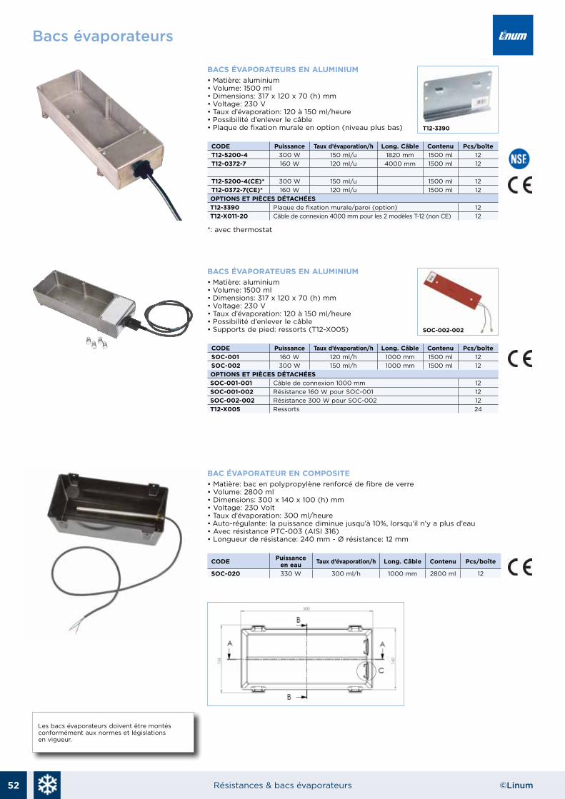
52 Résistances & bacs évaporateurs ©Linum
BACS ÉVAPORATEURS EN ALUMINIUM• Matière: aluminium• Volume: 1500 ml• Dimensions: 317 x 120 x 70 (h) mm• Voltage: 230 V• Taux d’évaporation: 120 à 150 ml/heure• Possibilité d’enlever le câble• Plaque de fixation murale en option (niveau plus bas)
CODE Puissance Taux d’évaporation/h Long. Câble Contenu Pcs/boîteT12-5200-4 300 W 150 ml/u 1820 mm 1500 ml 12T12-0372-7 160 W 120 ml/u 4000 mm 1500 ml 12
T12-5200-4(CE)* 300 W 150 ml/u 1500 ml 12T12-0372-7(CE)* 160 W 120 ml/u 1500 ml 12OPTIONS ET PIÈCES DÉTACHÉEST12-3390 Plaque de fixation murale/paroi (option) 12T12-X011-20 Câble de connexion 4000 mm pour les 2 modèles T-12 (non CE) 12
*: avec thermostat
Bacs évaporateurs
c: 100m: 65y: 0k: 0
Les bacs évaporateurs doivent être montésconformément aux normes et législations en vigueur.
BACS ÉVAPORATEURS EN ALUMINIUM• Matière: aluminium• Volume: 1500 ml• Dimensions: 317 x 120 x 70 (h) mm• Voltage: 230 V• Taux d’évaporation: 120 à 150 ml/heure• Possibilité d’enlever le câble• Supports de pied: ressorts (T12-X005)
CODE Puissance Taux d’évaporation/h Long. Câble Contenu Pcs/boîteSOC-001 160 W 120 ml/h 1000 mm 1500 ml 12SOC-002 300 W 150 ml/h 1000 mm 1500 ml 12OPTIONS ET PIÈCES DÉTACHÉESSOC-001-001 Câble de connexion 1000 mm 12SOC-001-002 Résistance 160 W pour SOC-001 12SOC-002-002 Résistance 300 W pour SOC-002 12T12-X005 Ressorts 24
BAC ÉVAPORATEUR EN COMPOSITE• Matière: bac en polypropylène renforcé de fibre de verre• Volume: 2800 ml• Dimensions: 300 x 140 x 100 (h) mm• Voltage: 230 Volt• Taux d’évaporation: 300 ml/heure• Auto-régulante: la puissance diminue jusqu’à 10%, lorsqu’il n’y a plus d’eau• Avec résistance PTC-003 (AISI 316)• Longueur de résistance: 240 mm - Ø résistance: 12 mm
CODE Puissance en eau Taux d’évaporation/h Long. Câble Contenu Pcs/boîte
SOC-020 330 W 300 ml/h 1000 mm 2800 ml 12
EVAPORATOR TRAY - CALORFLEX DTHP0003
Self-extinguish plastic evaporator tray which complies to UL94 V0 directive. This tray can be supplied together with the self- regulating cartridge heater CPTCx.
Calorflex srl Via Chiesa 71 31047 Negrisia di Ponte di Piave (TV) Italy – Tel.+39 0422 854673 Fax +39 0422 854973
C.F. e P.I. IT 03984740260 - www.calorflex.eu - [email protected]
T12-3390
SOC-002-002

53Résistances & bacs évaporateurs©Linum
Bacs évaporateurs
c: 100m: 65y: 0k: 0
RÉSISTANCES EN INOX POUR FABRICATION DE BAC ÉVAPORATEUR• Matière: inox AISI 316• Longueur câble: +/- 1 m• Système PTC, résistance en inox AISI 316 pour une meilleure résistance à la corrosion • Auto-régulante: la puissance diminue jusqu’à 10%, lorsqu’il n’y a plus d’eau
CODE Long. Tension Diamètre Matière Puissance en eau
Puissance àl’état sec
Taux d’évaporation
PTC-001 120 mm 230 V 12 mm AISI 316 110 W 10 W 110 ml/hPTC-002 180 mm 230 V 12 mm AISI 316 230 W 20 W 200 ml/hPTC-003 240 mm 230 V 12 mm AISI 316 330 W 30 W 300 ml/hPTC-004 270 mm 230 V 12 mm AISI 316 450 W 45 W 410 ml/h
BACS ÉVAPORATEURS EN POLYAMIDE OU EN ALUMINIUM• Matière: polypropylène renforcé de fibre de verre ou aluminium• Bacs évaporateurs sans résistance• Possiblité de montage avec résistance PTC-001/002/003/004• Conforme: UL94 V0
CODE Dimensions Matière ContenuPTC-020 325 x 200 x 41,5 (h) mm Renforcé de fibre de verre PA6 2000 mlPTC-030 301 x 40 x 223 (h) mm Renforcé de fibre de verre PA6 2500 mlPTC-040 300 x 150 x 60 (h) mm Aluminium 2500 mlPTC-0050 280 x 130 x 72 (h) mm Aluminium 1900 ml
PTC-020
PTC-030
PTC-040
PTC-0050
Peso Líquido
Código:
F.01
1.B
Desenhou
Aprovou
Escala
Tolerância
Rúbrica Material:
Planificado:
Dim.:
Data
@ Reprodução interdita sem autorização expressa da FAJOTACAD File:
Peso Bruto
Rev 1 Rev 2 Rev 3 Rev 4
Designação:
+-
Acabamento:
Ferram.:
Bandeja de Evaporação em Aluminio
AC 1199
10-11-2017
D:\Dossier de Produto\498 AC 1198-1199\bandeja.ipt
10-11-2017
572 Gr
Aluminio
09-05-08 10-11-17
0.50
S/E
280,0
273,0123,4
60,5
27,0
Fazer furo
s/ Resistência
Rosca M6 até ao fundo
Materiais: 1 - Bandeja em Aluminio2 - Parafusos Sext. ou Umb. M6x8
42,0
n18
,0