Embed Size (px)
Citation preview
110H NAL HOMOLOGATION FORM
ENGINE
NATIO Homologation N°
Manufacturer BRP-POWERTRAIN GMBH & CO KG
Make ROTAX
Model 125 MICRO MAX
Validity of the homologation 6 years
Number of pages 25 Plus Appendix This Homologation Form reproduces descriptions, illustrations and dimensions of the engine at the time that Karting Australia
conducted the homologation.
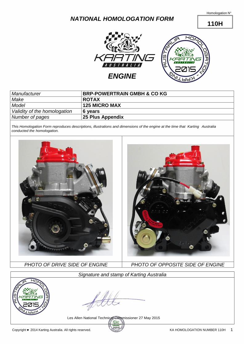
PHOTO OF DRIVE SIDE OF ENGINE PHOTO OF OPPOSITE SIDE OF ENGINE
Signature and stamp of Karting Australia
Les Allen National Technical Commissioner 27 May 2015
Copyright 2014 Karting Australia. All rights reserved. KA HOMOLOGATION NUMBER 110H 1

PHOTO OF DRIVE SIDE OF THE COMPLETE ENGINE
KA HOMOLOGATION NUMBER 110H 2 Copyright 2014 Karting Australia. All rights reserved.

KA HOMOLOGATION NUMBER 110H 3 Copyright 2014 Karting Australia. All rights reserved.
PHOTO OF OPPOSITE DRIVE SIDE OF THE COMPLETE ENGINE

KA HOMOLOGATION NUMBER 110H 4 Copyright 2014 Karting Australia. All rights reserved.
PHOTO OF THE REAR OF THE COMPLETE ENGINE

KA HOMOLOGATION NUMBER 110H 5 Copyright 2014 Karting Australia. All rights reserved.
PHOTO OF THE FRONT OF THE COMPLETE ENGINE

KA HOMOLOGATION NUMBER 110H 6 Copyright 2014 Karting Australia. All rights reserved.
PHOTO OF THE COMPLETE ENGINE TAKEN FROM ABOVE
KA HOMOLOGATION NUMBER 110H 7 Copyright 2014 Karting Australia. All rights reserved.
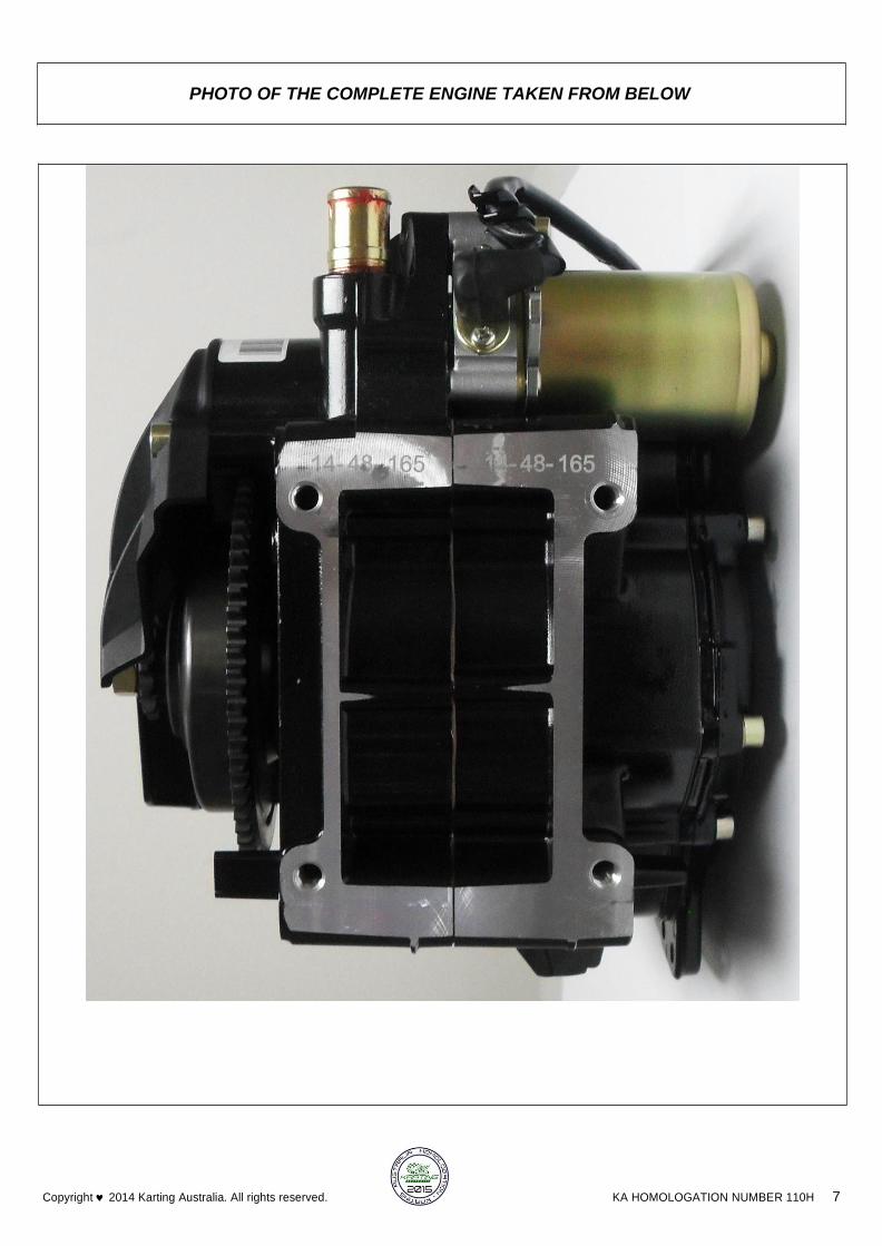
PHOTO OF THE COMPLETE ENGINE TAKEN FROM BELOW
KA HOMOLOGATION NUMBER 110H 8 Copyright 2014 Karting Australia. All rights reserved.
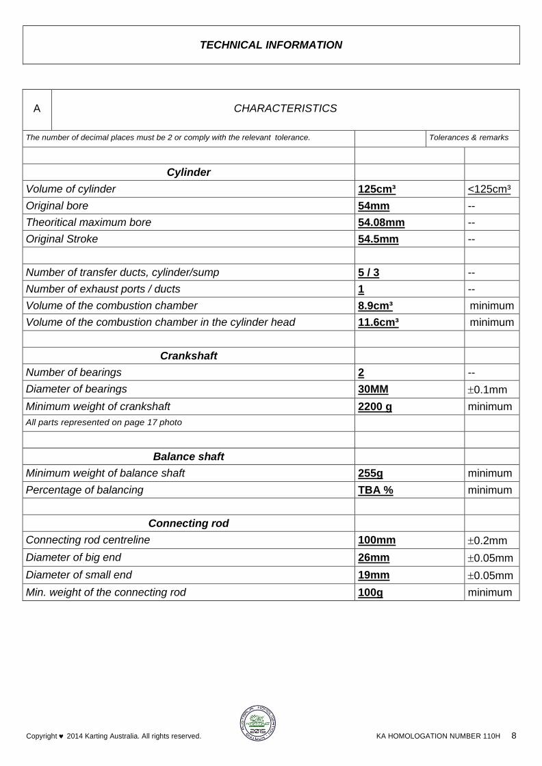
TECHNICAL INFORMATION
A
CHARACTERISTICS
The number of decimal places must be 2 or comply with the relevant tolerance. Tolerances & remarks
Cylinder
Volume of cylinder 125cm³ <125cm³
Original bore 54mm --
Theoritical maximum bore 54.08mm --
Original Stroke 54.5mm --
Number of transfer ducts, cylinder/sump 5 / 3 --
Number of exhaust ports / ducts 1 --
Volume of the combustion chamber 8.9cm³ minimum
Volume of the combustion chamber in the cylinder head 11.6cm³ minimum
Crankshaft
Number of bearings 2 --
Diameter of bearings 30MM 0.1mm
Minimum weight of crankshaft 2200 g minimum
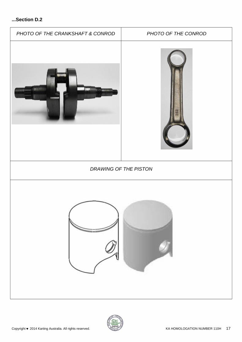
All parts represented on page 17 photo
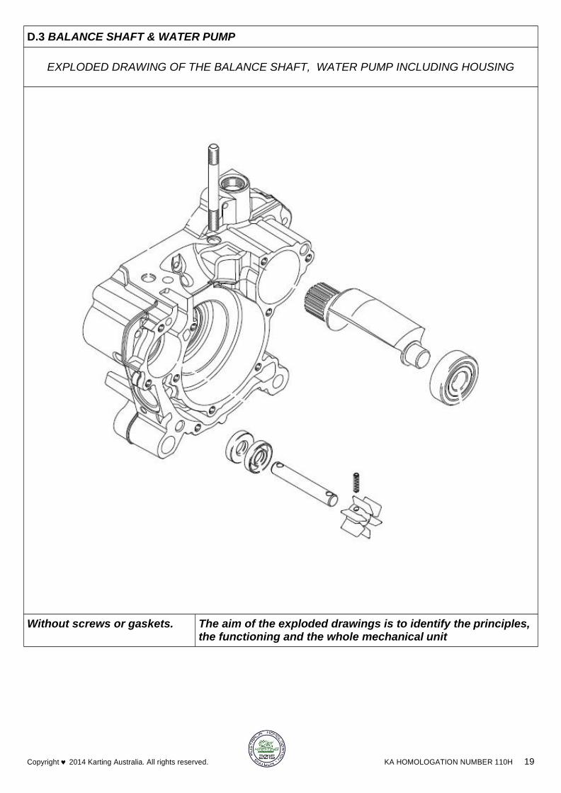
Balance shaft
Minimum weight of balance shaft 255g minimum
Percentage of balancing TBA % minimum
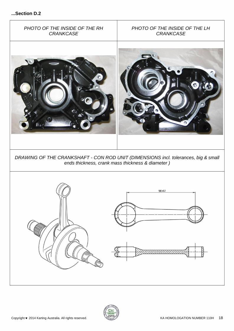
Connecting rod
Connecting rod centreline 100mm 0.2mm
Diameter of big end 26mm 0.05mm
Diameter of small end 19mm 0.05mm
Min. weight of the connecting rod 100g minimum

KA HOMOLOGATION NUMBER 110H 9 Copyright 2014 Karting Australia. All rights reserved.
Piston
Number of piston rings 1
Min. weight of the bare piston 125g minimum
Gudgeon pin
Diameter 15mm 0.05mm
Length 45.6mm 0.15mm
Minimum weight 32.1g Minimum
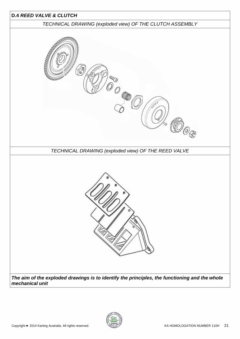
Clutch
Minimum weight 1000g minimum
Of all the parts represented on the page 21 technical drawing
B
OPENING ANGLES
Of the inlet (main transfer ports) 119.5° 2°
Of the inlet (secondary transfer ports, for 5 transfer ducts engine) 120° 2°
Of the exhaust 178° 2°
Of the boosters 118° 2° * Angular reading by inserting a 0.2 x 5mm gauge.
C
MATERIAL
Cylinder head ALUMINIUM
Cylinder ALUMINIUM
Cylinder wall GILNISIL COATED
Sump ALUMINIUM
Crankshaft STEEL
Connecting rod STEEL-ALLOY
Piston ALUMINIUM

KA HOMOLOGATION NUMBER 110H 10 Copyright 2014 Karting Australia. All rights reserved.
D.1 CYLINDER UNIT
EXPLODED DRAWING OF THE CYLINDER, CYLINDER HEAD AND EXHAUST MANIFOLD UNIT
* For 125 Micro Max / 125 Mini Max only!
To achieve the defined minimum squish gap, one Restriction Plate with same shape as cylinder base gasket in
combination with at least two cylinder base gaskets (one below the spacer and one above the spacer) must be
used.The squish gap must be measured with a certified slide gauge and by using a 3 mm tin wire (Rotax Part
No. 580 132).
Squish Gap for 125 Micro Max / 125 Mini Max only!
125 Micro MAX/evo minimum = 2,40 mm
125 Mini MAX/evo minimum = 2,40 mm
Without screws or gaskets. The aim of the exploded drawings is to identify the principles, the functioning and the whole mechanical unit
D
PHOTOS, DRAWINGS & GRAPHS
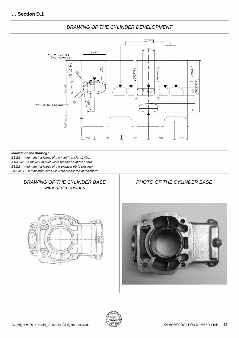
… Section D.1
KA HOMOLOGATION NUMBER 110H 11 Copyright 2014 Karting Australia. All rights reserved.
DRAWING OF THE CYLINDER DEVELOPMENT
Indicate on the drawing :
B1/B2 = minimum thickness of the inlet (transferts) ribs.
A1/A2/A… = maximum inlet width measured at the chord.
E1/E2 = minimum thickness of the exhaust rib (if existing).
C1/C2/C… = maximum exhaust width measured at the chord.
DRAWING OF THE CYLINDER BASE without dimensions
PHOTO OF THE CYLINDER BASE

… Section D.1
KA HOMOLOGATION NUMBER 110H 12 Copyright 2014 Karting Australia. All rights reserved.
DRAWING OF THE CYLINDER HEAD AND OF THE COMBUSTION CHAMBER without dimensions
PHOTO OF THE CYLINDER HEAD PHOTO OF THE COMBUSTION CHAMBER IN THE CYLINDER HEAD

… Section D.1
KA HOMOLOGATION NUMBER 110H 13 Copyright 2014 Karting Australia. All rights reserved.
VERTICAL CROSS SECTION VIEW OF CYLINDER WITH LINER, without dimensions
PHOTO OF THE CYLINDER FROM ABOVE PHOTO OF THE CYLINDER FROM RH SIDE

KA HOMOLOGATION NUMBER 110H 14 Copyright 2014 Karting Australia. All rights reserved.
... Section D.1
EXHAUST DUCT LENGTH
ANGLE in ° Minimum in mm
--° +/-1° -- mm
The L min. dimension will be the result of the value taken on the reference engine minus 5 mm.
Technical Drawing No.13
N/A TO 125 MICRO MAX
A: Centring guide centred in relation to the exhaust duct by the exhaust manifold fixation screws, with a total thickness of 20
+/- 0.05 mm and being drilled in its centre by a hole with a 5 mm diameter, H7 bore.
B: Control gauge composed of a shaft with a 5g6 diameter having a 2.5 mm radius at its end and a length = L min + 20+10.
TRANSFER DUCTS VOLUME
Transfer position on
5-transfer cylinder
Transfer position on
3-transfer cylinder
TRANSFER No.
VOLUME
in cm3
LH 1 RH 1
LH 2 RH 2
5
LH 1 RH 1
3
Transfer No. 1 LH --.-- +/- 5 %
Transfer No. 2 LH --.-- +/- 5 %
Transfer No. 3 or 5 --.-- +/- 8 %
Transfer No. 2 RH --.-- +/- 5 %
Transfer No. 1 RH --.-- +/- 5 %

KA HOMOLOGATION NUMBER 110H 15 Copyright 2014 Karting Australia. All rights reserved.
... Section D.1
Technical Drawing No.13 bis
FRONT VIEW DRAWING – with dimensions
Minimum template Maximum template
Measurement ‘C’ must be minimum 15.5mm
Measurement ‘C’ must me maximum 16.5mm
Maximum template: internal profile of the gasket plane of the manifold
of the original cylinder plus 1 mm
Minimum template: internal profile of the gasket plane of the manifold
of the original cylinder minus 1 mm
Thickness: 5 +/- 0,05 mm
INTERNAL PROFILE OF THE EXHAUST DUCT
Templates of the internal dimensions of the exhaust duct: gasket plane of the manifold.

KA HOMOLOGATION NUMBER 110H 16 Copyright 2014 Karting Australia. All rights reserved.
D.2 CONROD, CRANKCASE, CRANKSHAFT & PISTON
EXPLODED DRAWING OF THE PISTON, CRANKSHAFT, CONNECTING ROD AND CRANKCASES UNIT (exploded crankshaft)
Without screws or gaskets. The aim of the exploded drawings is to identify the principles, the functioning and the whole mechanical unit
KA HOMOLOGATION NUMBER 110H 17 Copyright 2014 Karting Australia. All rights reserved.
...Section D.2
PHOTO OF THE CRANKSHAFT & CONROD PHOTO OF THE CONROD
DRAWING OF THE PISTON
KA HOMOLOGATION NUMBER 110H 18 Copyright 2014 Karting Australia. All rights reserved.
...Section D.2
PHOTO OF THE INSIDE OF THE RH CRANKCASE
PHOTO OF THE INSIDE OF THE LH CRANKCASE
DRAWING OF THE CRANKSHAFT - CON ROD UNIT (DIMENSIONS incl. tolerances, big & small ends thickness, crank mass thickness & diameter )
KA HOMOLOGATION NUMBER 110H 19 Copyright 2014 Karting Australia. All rights reserved.
D.3 BALANCE SHAFT & WATER PUMP
EXPLODED DRAWING OF THE BALANCE SHAFT, WATER PUMP INCLUDING HOUSING
Without screws or gaskets. The aim of the exploded drawings is to identify the principles, the functioning and the whole mechanical unit

…Section D.3
KA HOMOLOGATION NUMBER 110H 20 Copyright 2014 Karting Australia. All rights reserved.
PHOTO OF THE BALANCE SHAFT PHOTO OF THE WATER PUMP IMPELLER
DRAWING OF THE BALANCE SHAFT (DIMENSIONS incl. tolerances)
KA HOMOLOGATION NUMBER 110H 21 Copyright 2014 Karting Australia. All rights reserved.
D.4 REED VALVE & CLUTCH
TECHNICAL DRAWING (exploded view) OF THE CLUTCH ASSEMBLY
TECHNICAL DRAWING (exploded view) OF THE REED VALVE
The aim of the exploded drawings is to identify the principles, the functioning and the whole mechanical unit

KA HOMOLOGATION NUMBER 110H 22 Copyright 2014 Karting Australia. All rights reserved.
… Section D.4
DRAWING OF THE REED VALVE (DIMENSIONS incl. tolerances)
DRAWING OF THE REED VALVE COVER (only basic engine)

KA HOMOLOGATION NUMBER 110H 23 Copyright 2014 Karting Australia. All rights reserved.
D.5 EXHAUST SYSTEM
PHOTO OF THE EXHAUST MANIFOLD
Maximum inner diameter of exhaust socket is:-
- 18.2mm (125 Micro Max)
PHOTO OF THE EXHAUST
Exhaust for 125 Micro Max
TECHNICAL DESCRIPTIONS OF THE EXHAUST (Art. 8.9.3 of HR)
Weight in g - MICRO MAX: 2300G Minimum
Volume in cc +/-5 %
KA HOMOLOGATION NUMBER 110H 24 Copyright 2014 Karting Australia. All rights reserved.
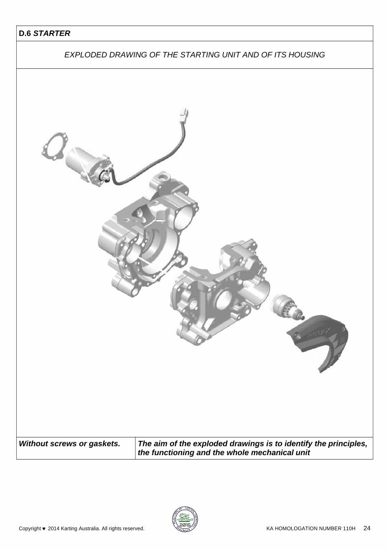
D.6 STARTER
EXPLODED DRAWING OF THE STARTING UNIT AND OF ITS HOUSING
Without screws or gaskets. The aim of the exploded drawings is to identify the principles, the functioning and the whole mechanical unit

KA HOMOLOGATION NUMBER 110H 25 Copyright 2014 Karting Australia. All rights reserved.
Ignition homologation No. Dellorto Ignition System
Ignition homologation No. Ignition Coil is labelled with two stickers ‘’BRP 666820’’ & ‘‘NIG0105’’
Ignition homologation No. Electronic box is labelled with sticker ‘’666814, 125 MAX evo’’
Code F125 --/M/18 Color yellow
IGNITION SYSTEM
D.7 ELECTRICAL SYSTEM
TECHNICAL SPECIFICATIONS – JUNIOR (MICRO) – (A) FR 125 MAX (NON EVO) OR (B) FR 125 MAX (EVO)
AUSTRALIA - Version: 1 2 June 2015 Page: 1 of 36
Appendix A to ROTAX MICRO MAX Homologation Documents
The following notes are additional to the details contained in these Homologation documents for the ROTAX
MICRO MAX engine (the “Engine”) and are to be read in conjunction with the specifications and details contained
therein. They form part of the Homologation documents for the Engine.
The Engine must at all times be used and be presented in strict conformity with the specifications detailed in the
homologation documents. Unless otherwise expressly permitted by Karting Australia, only Rotax OEM parts
that have been manufactured and/or supplied by Rotax for the Engine are permitted to be used in the Engine
at any time.
Neither the Engine nor any of its ancillary components may be modified other than in accordance with the Rules,
these Homologation and Technical Specification documents.
UNLESS IN THE KARTING AUSTRALIA RULES AND/OR THESE HOMOLOGATION AND
TECHNICAL SPECIFICATION DOCUMENTS IT SAYS THAT YOU CAN, THEN YOU
CANNOT.
FOR AUSTRALIAN COMPETITION
GENERAL
1. EVO ENGINE INTRODUCTION INTO AUSTRALIAN KARTING
The introduction of the Rotax EVO Engines into Australia will be separated into two distinct categories:
a. Engines that are to be used in all Rotax Pro Tour National Series Competition Classes; and
b. Engines that are to be used in non-‐Rotax Pro Tour Competition Classes including; KA TaG, Tag
125, TaG 125 Restricted, Junior Max, Rotax 125 and DD2.
2. “NON EVO”, “UPGRADED TO EVO” OR “FULL EVO 2015”
a. A “FULL EVO 2015 ENGINE” (EVO) is a complete new Rotax EVO Engine including exhaust system
as homologated by KA in 2015 and that has been purchased from IKD after 1 January 2015.
i. A FULL EVO 2015 ENGINE must use all of the EVO Components supplied save that it is
permitted for an “EVO” Engine to use a cylinder head cover that is not red, and a
crankcase that is not black.
b. An “UPGRADED TO EVO ENGINE” (EVO) is a previously homologated Junior Max, Rotax 125 or
DD2 engine (“Older Engines”) that has been wholly or partially upgraded to EVO Engine
specification by the addition of any of the Performance Components listed herein.
i. Note that for Rotax Pro Tour Competition, if any of the Performance Components are
used on the Engine, all of the Performance Components must be used.
ii. Note that for non-‐Rotax Pro Tour Competition, the Engine can be partially Upgraded to
EVO Engine specification by the use of any of the Performance Components (in which
case it will still be considered to be an “Upgraded to EVO Engine”).

TECHNICAL SPECIFICATIONS – JUNIOR (MICRO) – (A) FR 125 MAX (NON EVO) OR (B) FR 125 MAX (EVO)
AUSTRALIA - Version: 1 2 June 2015 Page: 2 of 36
iii. For the sake of absolute clarity, the EVO Exhaust System and EVO Exhaust Socket are not
designated by Rotax or IKD to be Performance Components and are not required to be
fitted to an Upgraded To EVO Engine.
c. A “NON EVO ENGINE” (NON EVO) is a previously homologated Junior Max, Rotax 125 or DD2
engine (“Older Engines”) that has not been wholly or partially upgraded to EVO Engine
specification by the addition of any of the Performance Components listed herein.
i. A “Non EVO Engine” is permitted to use the “EVO” Exhaust System, “EVO” Exhaust
Socket, “EVO” Conrod, “EVO” Crankshaft, “EVO” Piston and “EVO” Battery Holding Unit
and Switches.
3. EVO PERFORMANCE COMPONENTS
All EVO performance components are external only. EVO Performance Components are:
a. Carburettor “VHSB 34 XS” (Rotax Part no. 295 060)
b. Dellorto Ignition System with Electronic Box (Rotax part no. 666 812)
Once an engine is determined to be either “NON EVO”, or “EVO” (Includes both “UPGRADED TO EVO” and
“Full EVO 2015” Engines) the relevant Technical Specifications outlined in this document apply to that Engine.
4. The introduction of the new Rotax EVO Engine to Australian competition will be done according to the
following principles.
5. Rotax Pro Tour Events
a. Rotax World Rules as approved by KA for Australia will apply to these events commencing at
Rotax Pro Tour Round 4, 2015.
b. EVO Engines will be permitted to be used in accordance with the homologation of these engines.
c. Previously homologated Junior Max, Rotax 125 and DD2 engines (the “Older Engines”) will
remain eligible for competition in Rotax Pro Tour events.
d. There will be no parity adjustments to equalize the EVO Engines and the Older Engines in the
Rotax Pro Tour.
e. Older Engines can be upgraded at any time to full EVO Engine specification using the EVO
Performance Components.

TECHNICAL SPECIFICATIONS – JUNIOR (MICRO) – (A) FR 125 MAX (NON EVO) OR (B) FR 125 MAX (EVO)
AUSTRALIA - Version: 1 2 June 2015 Page: 3 of 36
(A) FR 125 JUNIOR MAX (NON EVO) SPECIFICATION ONLY–WITHIN THE ENGINE SEAL
Squish Gap
A1.1
A1.2
FR 125 Junior Max: Minimum = 2.4mm
The squish gap must be measured with a certified
slide gauge and by using a 3 mm tin wire (Rotax
part no. 580 132). The crankshaft must be turned
by hand slowly over top dead centre to squeeze
the tin wire. The squish gap must be measured on
the left and right side in the direction of the piston
pin. The average value of the two measurements
counts.
Combustion
A2.1
Cast identification code has to be "223 389" or
Chamber "223 389 1" or "223 389 2" or 223 389 2/1" or
Insert “223 389 2/2”.
A2.2 Casted wording "ROTAX" and/or "MADE IN
AUSTRIA" must be shown
A2.3 Heights of combustion chamber insert have to be
27.55 mm with a tolerance of +0.0/-0,1 mm (A)
and 28.80 mm with a tolerance of +/- 0.2 mm (B).
A2.4 The profile of the combustion chamber insert has
to be checked with a template (ROTAX part no.
277 390). The crack of light between the template
and the profile of the combustion chamber insert
has to be the same over the whole profile.
NOTE: If the combustion chamber insert fails the
template check as described herein, detailed
measurements of the combustion chamber insert
must be taken to determine conformity or non-
conformity of the component.
Piston with
Ring
Assembly
A3.1
A3.2
A3.3
Original, coated or uncoated, aluminium, cast
piston with one piston ring. The piston has to
show on the inside of the cast wording "MADE IN
AUSTRIA" (Image 1) and "ELKO" (Image 2).
Machined areas are: Top end of piston, outside
diameter, groove for the piston ring, bore for the
piston pin, inside diameter at bottom end of piston
and some pre-existing factory removal (Image 3)
of flashing at the cut out of the piston skirt. All
other surfaces are not machined and have cast
surface.
Any mechanical treatment or rework of the piston
is forbidden, (e.g. removal of carbon deposits).
Cleaning without changing the original surface is
allowed.

TECHNICAL SPECIFICATIONS – JUNIOR (MICRO) – (A) FR 125 MAX (NON EVO) OR (B) FR 125 MAX (EVO)
AUSTRALIA - Version: 1 2 June 2015 Page: 4 of 36
A3.4
A3.5
Original, magnetic, rectangular piston ring.
Ring height: 0,98 +/- 0,02 mm.
Piston ring is marked either with "ROTAX 215
547" or "ROTAX 215 548".
Piston Pin
(Gudgeon
Pin)
A4.1
A4.2
A4.3
Piston pin is made out of magnetic steel.
Dimensions must be according to the drawing.
The minimum weight of the piston pin must not be
lower than 32.10 grams.
Cylinder
A5.1
Light-alloy-cylinder with GILNISIL-plating.
Any re-plating of cylinder is not allowed.
A5.2 Cylinder with one main exhaust port and no
exhaust valve.
A5.3 Maximum bore of cylinder = 54,035mm
(measured 10 mm above the exhaust port).
A5.4 Cylinder has to be marked with the "ROTAX" logo
(see pictures).
A5.5.1 Cylinder has to be marked either identification
code 223 998, 223 994 (see pictures).
A5.5.2
Cylinder 223 999 is outlawed.
A5.6
Height of cylinder has to be 87mm -0.05/+0.1mm
(measured with a digital calliper).
A5.7.1
All transfer ports and passages have cast finish
surface except some removal (done by the
manufacturer) of cast burr at the inlet passage,
exhaust port and passages. All ports have
chamfered edges to prevent ring snagging. Any
additional machining is not permitted. The top
TECHNICAL SPECIFICATIONS – JUNIOR (MICRO) – (A) FR 125 MAX (NON EVO) OR (B) FR 125 MAX (EVO)
AUSTRALIA - Version: 1 2 June 2015 Page: 5 of 36
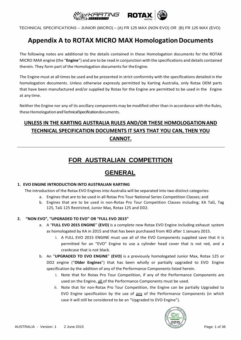
A5.7.2
edge of exhaust port may show some pre-existing
machining from the manufacturer. The sealing
flange for the exhaust socket may show signs of
machining from the manufacturer.
All ports have chamfered edges. Any additional
machining is not permitted.
A5.7.3
On cylinders marked 223 994 the upper edge of
the central boost port may show factory
machining.
A5.7.4
The flange for the exhaust socket may show
either cast finish or machined surface. Machined
surface can be either flat or show a circular
sealing bump.
A5.7.5
The top edge of the exhaust port may show either
just a cast finish surface (Image1) or signs of
CNC machining (Image2) or signs of CNC
machining in combination with signs of manual
grinding (Image 3). The exhaust port may show
partial manual grinding done by the manufacturer
to eliminate minor casting defects and/or to
eliminate the NIKASIL burr at the end of the
NIKASIL plating (Image 3).
TECHNICAL SPECIFICATIONS – JUNIOR (MICRO) – (A) FR 125 MAX (NON EVO) OR (B) FR 125 MAX (EVO)
AUSTRALIA - Version: 1 2 June 2015 Page: 6 of 36
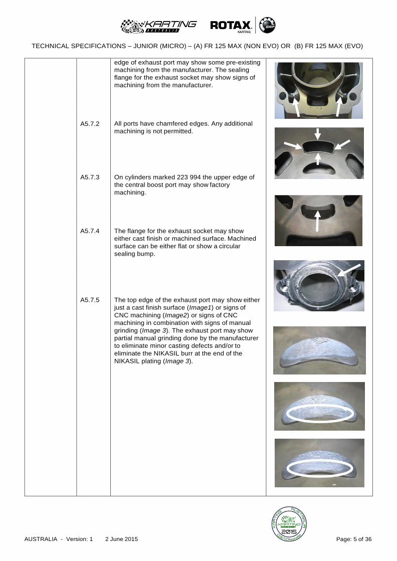
A5.7.6
A5.8
On cylinders marked 223 994 the exhaust port
may show factory machining all around.
FR 125 Junior Max: Cylinder 223 998 = 0.90 mm
Cylinder 223 994 = 1.10 mm
The "exhaust port timing" (distance from the top of
the cylinder to the top of the exhaust port) has to
be checked by means of the template (Rotax part
no. 277 397).
Insert the template into the cylinder, so that the
template is touching the cylinder wall and that the
finger of the template is located in the middle of
the exhaust port (highest point).
Move the template upwards, until the finger is
touching the top edge of the exhaust port. Insert a
filler gauge between the top of the cylinder and
the template. It must not be possible to fit the
feeler gauge specified below.
NOTE: Take care to use the corresponding gauge
of the template (JUN, MAX or DD2) for the
respective cylinder.
Inlet System
A6.1
A6.2
A6.3
A6.4
Inlet manifold is marked with the name "ROTAX"
and the identification code “267 915”
Some factory flash removal may be present at the
conjunction of the inside contour and the
carburettor stop mounting face. This is a manual
trimming operation consisting of a small corner
break of less than 3 mm in width. No additional
grinding or machining is permitted.
The reed valve assy. is equipped with 2 petal
stops and 2 reeds, each having 3 petals.
The thickness of the reeds is 0.6 mm +/- 0.10
mm.

TECHNICAL SPECIFICATIONS – JUNIOR (MICRO) – (A) FR 125 MAX (NON EVO) OR (B) FR 125 MAX (EVO)
AUSTRALIA - Version: 1 2 June 2015 Page: 7 of 36
Crankshaft
A7.1
A7.2
A7.3
A7.4
A7.5
Stroke 54.5 mm +/-0,1 mm
Con rod has to show forged numbers "213",
"365", "367" or “362” on shaft.
Shafts of con rods "213", "365" and "367" are not
machined and are copper plated (Image 1). Shaft
of con rod “362” is not copper plated and
blank/grey (Image 2).
Grinding or polishing of shaft of con rod is not
permitted.
Effective from 1st June 2012, crankshaft main
bearing 6206 from FAG only is allowed for
Rotax National Series, State Championships or
events where Rotax is run as a standalone class
(must be marked with code 579165BA or
Z-579165.11.KL). This does not apply to
Restricted TAG, TAG & Sportsman style
classes.
Balance Shaft
A8.1
A8.2
A8.3
A8.4
A8.5
Balance shaft and balance gears must be
installed
Configurations of part no. 237 949 (equal with 237
948) only is legal.
Surface (1) is not machined and must show cast
surface.
Measurement from centre of balance shaft to
outer diameter of fly weight of balance shaft at
defined length must not be lower than specified.
The minimum weight of the dry balance shaft
must not be lower than: 255 grams for balance
shaft Rotax part no. 237 949 (equal with 237 948).
Crankcase
A9.1
A9.2
As supplied by the manufacturer. No grinding or
polishing is permitted in the two main transfer
passages as well as in the crank area.
Uncoated as well as black coated crankcases are
legal to be used.
TECHNICAL SPECIFICATIONS – JUNIOR (MICRO) – (A) FR 125 MAX (NON EVO) OR (B) FR 125 MAX (EVO)
AUSTRALIA - Version: 1 2 June 2015 Page: 8 of 36
Balance Drive
A10.1
A10.2
A10.3
A10.4
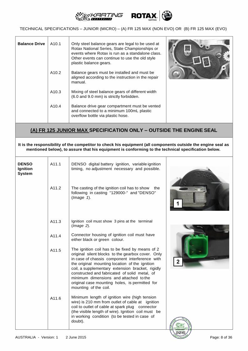
Only steel balance gears are legal to be used at
Rotax National Series, State Championships or
events where Rotax is run as a standalone class.
Other events can continue to use the old style
plastic balance gears.
Balance gears must be installed and must be
aligned according to the instruction in the repair
manual.
Mixing of steel balance gears of different width
(6.0 and 9.0 mm) is strictly forbidden.
Balance drive gear compartment must be vented
and connected to a minimum 100mL plastic
overflow bottle via plastic hose.
(A) FR 125 JUNIOR MAX SPECIFICATION ONLY – OUTSIDE THE ENGINE SEAL
It is the responsibility of the competitor to check his equipment (all components outside the engine seal as
mentioned below), to assure that his equipment is conforming to the technical specification below.
DENSO
A11.1
DENSO digital battery ignition, variable ignition
Ignition timing, no adjustment necessary and possible.
System
A11.2
The casting of the ignition coil has to show the
following in casting "129000-" and "DENSO"
(Image 1).
A11.3
Ignition coil must show 3 pins at the terminal
(Image 2).
A11.4 Connector housing of ignition coil must have
either black or green colour.
A11.5 The ignition coil has to be fixed by means of 2
original silent blocks to the gearbox cover. Only
in case of chassis component interference with
the original mounting location of the ignition
coil, a supplementary extension bracket, rigidly
constructed and fabricated of solid metal, of
minimum dimensions and attached to the
original case mounting holes, is permitted for
mounting of the coil.
A11.6 Minimum length of ignition wire (high tension
wire) is 210 mm from outlet of cable at ignition
coil to outlet of cable at spark plug connector
(the visible length of wire). Ignition coil must be
in working condition (to be tested in case of
doubt).

TECHNICAL SPECIFICATIONS – JUNIOR (MICRO) – (A) FR 125 MAX (NON EVO) OR (B) FR 125 MAX (EVO)
AUSTRALIA - Version: 1 2 June 2015 Page: 9 of 36
A11.7
A11.8
A11.9
A11.10
The pick-up must be marked with the numbers
029600-0710, followed by a variable production
code in the 2nd line (Image 3).
HINT: In case of doubt, an easy check is to
place a steel ball (3-5 mm in diameter) on the
pick-up (engine side). The steel ball must stay
in the center of the pick-up surface.
Spark plug cap must be marked with
“NGK TB05EMA” (Image 4).
Battery must be fitted to the chassis with at
least 2 screws. Position of the battery is free.
The earth strap may be fitted with a connector
for ease of removal of the engine. Rotax Wiring
Harness must be OEM only, with no fittings or
repairs. The ignition coil can be relocated from
the crankcase as far as the OEM harness will
permit.
Centrifugal
A13.1
Dry centrifugal clutch with engagement maximum
Clutch at 4,000 r.p.m.
This means that the kart must start to move
before the engine speed reaches
4,000 r.p.m.
There are 2 versions of the steel clutch (Image 1)
and both are legal to be used. The older version
can be either untreated or nitrated configuration.
A13.2.1 Needle cage bearing 15x19x17 (Rotax part no.
632 415) must be fitted for 12, 13, 14 & 15 tooth
sprockets. Plain bearing 15x17x20 (Rotax part no.
233 855) must be fitted for 11 tooth sprockets.
(Image 2)
A13.2.2 O-Ring 12x2.5 (Rotax part no. 950 815) must be
fitted and must assure an appropriate sealing
between the clutch drum and the needle/plain
bearing.
A13.3 No extra lubrication or substance is allowed inside
the clutch drum, in addition to the grease that
originates from lubrication of the needle cage
bearing, and enters the clutch area.
See (Images) showing worst case scenario of
when grease exits the needle bearing area, even
with the O-Ring installed. Only the fixation nut and
the inside of the drum show signs of grease. The
running surface of the drum is completely dry.
When the plain bearing for 11 tooth sprockets is
used, the clutch area must be absolutely free of
grease or any additional substance.
TECHNICAL SPECIFICATIONS – JUNIOR (MICRO) – (A) FR 125 MAX (NON EVO) OR (B) FR 125 MAX (EVO)
AUSTRALIA - Version: 1 2 June 2015 Page: 10 of 36
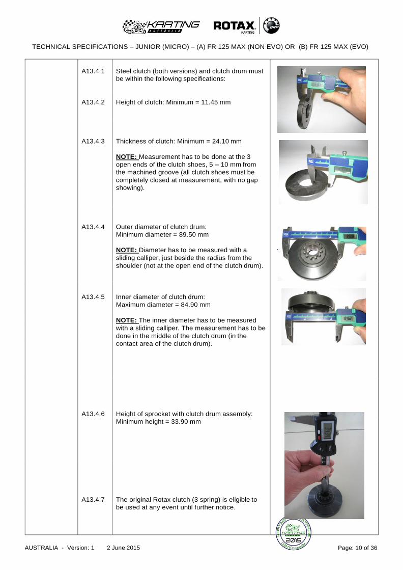
A13.4.1
Steel clutch (both versions) and clutch drum must
be within the following specifications:
A13.4.2
Height of clutch: Minimum = 11.45 mm
A13.4.3
Thickness of clutch: Minimum = 24.10 mm
NOTE: Measurement has to be done at the 3
open ends of the clutch shoes, 5 – 10 mm from
the machined groove (all clutch shoes must be
completely closed at measurement, with no gap
showing).
A13.4.4
Outer diameter of clutch drum:
Minimum diameter = 89.50 mm
NOTE: Diameter has to be measured with a
sliding calliper, just beside the radius from the
shoulder (not at the open end of the clutch drum).
A13.4.5
Inner diameter of clutch drum:
Maximum diameter = 84.90 mm
NOTE: The inner diameter has to be measured
with a sliding calliper. The measurement has to be
done in the middle of the clutch drum (in the
contact area of the clutch drum).
A13.4.6
Height of sprocket with clutch drum assembly:
Minimum height = 33.90 mm
A13.4.7
The original Rotax clutch (3 spring) is eligible to
be used at any event until further notice.

TECHNICAL SPECIFICATIONS – JUNIOR (MICRO) – (A) FR 125 MAX (NON EVO) OR (B) FR 125 MAX (EVO)
AUSTRALIA - Version: 1 2 June 2015 Page: 11 of 36
Intake
Silencer
A14.1
A14.2
A14.3
A14.4
A14.5
Intake silencer with integrated, washable air filter
has to be used with all parts as shown in the
illustration and has to be mounted on the support
bracket with two screws (in dry and wet
condition).
Intake Silencer case bottom is marked on .the
inside with the Rotax part no. “225 015”
Intake Silencer case top is marked on the inside
with the Rotax part no. “225 025”.
Air filter must be installed as shown in illustration.
The original square type intake silencer is not
eligible to be used for Rotax National Series,
State Championships or events where Rotax is
run as a standalone class. It can be used in
Restricted TAG, TAG and Sportsman style
classes.
Carburettor
A15.1
A15.2
A15.3
A15.4
A15.5
A15.6
A15.7
Dellorto carburettor with “VHSB 34” cast in the
housing of the carburettor.
“QD” or “QS” is stamped in the housing of the
carburettor.
The complete inlet bore in the casting of the
carburettor must show a cast surface.
Carburettor Slide shows digits “40” in casting
Jet needle stamped with “K98” only.
Settings of the carburettor adjustment screws are
free.
The following two combinations of floats and idle
jets are legal:
Combination 1:
For carburettor insert 12.5 (as per illustration at
rule 15.16.1) floats marked with “5.2gr” must be
used. Idle Jet and Idle Jet Insert stamped with the
digits “30” must be used.
Combination 2:
For carburettor insert 8.5 (as per illustration at rule
15.16.1) floats marked with “3.6gr” must be used.
Idle Jet and Idle Jet Insert stamped with the digits
“60” must be used.
NOTE: Effective from 1st
January 2014, only
Combination 2 is allowed for Rotax National
Series, State Championships or events where
Rotax is run as a standalone class. This does not
apply to Restricted TAG, TAG and Sportsman
style classes.

TECHNICAL SPECIFICATIONS – JUNIOR (MICRO) – (A) FR 125 MAX (NON EVO) OR (B) FR 125 MAX (EVO)
AUSTRALIA - Version: 1 2 June 2015 Page: 12 of 36
A15.8
All jets must be correctly seated and securely
fitted.
A15.9 A minimum required size of Main Jet may be
determined for each race event by a
“Supplementary Regulation”.
A15.10
Needle Valve assembly stamped with the digits
“150” (Image 1)
A15.11
Needle of Needle Valve marked with diamond
symbol “INC” only (Image 2).
A15.12
Start Jet is stamped with the digits “60”.
A15.13.1 Needle Jet is stamped with “FN 266”.
A15.13.2 Total length of Needle Jet = 54.00 +/- 0.3 mm
A15.13.3
Length of bottom section of Needle Jet
= 11.50 +/- 0.2 mm
A15.13.4
Top bore diameter of Needle Jet
= 2.60 +/- 0.15 mm
(measured 2mm inside)

TECHNICAL SPECIFICATIONS – JUNIOR (MICRO) – (A) FR 125 MAX (NON EVO) OR (B) FR 125 MAX (EVO)
AUSTRALIA - Version: 1 2 June 2015 Page: 13 of 36
A15.13.5
4 x 4 cross holes diameter of Needle Jet:
Plug gauge 0.90 mm may NOT enter one of the
16 cross holes of the Needle Jet.
NOTE: Use jet gauge set (Rotax part no. 281
920)
A15.14.1
Idle Jet 30 and Idle Jet Insert 30 must be used
with carburettor insert stamped 12.5, as per
illustration at rule A15.16.1.
A15.14.2 Plug gauge 0.40 mm may NOT enter the bore of
the Idle Jet 30.
NOTE: Use jet gauge set (Rotax part no. 281
920)
A15.14.3
Plug gauge 0.40 mm may NOT enter the bore of
the Idle Jet Insert 30.
NOTE: Use jet gauge set (Rotax part no. 281
920)
A15.14.4
Plug gauge 0.40 mm may NOT enter one of the 4
cross bores of the Idle Jet Insert 30.
NOTE: Use jet gauge set (Rotax part no. 281
920)
A15.15.1
Idle Jet 60 and Idle Jet Insert 60 must be used
with carburettor insert stamped 8.5, as per
A15.15.2 illustration at rule A15.16.1.
Plug gauge 0.65 mm may NOT enter the bore of
the Idle Jet 60.
NOTE: Use jet gauge set (Rotax part no. 281
920)
A15.15.3
Plug gauge 0.65 mm may NOT enter the bore of
the Idle Jet Insert 60.
NOTE: Use jet gauge set (Rotax part no. 281
920)
TECHNICAL SPECIFICATIONS – JUNIOR (MICRO) – (A) FR 125 MAX (NON EVO) OR (B) FR 125 MAX (EVO)
AUSTRALIA - Version: 1 2 June 2015 Page: 14 of 36
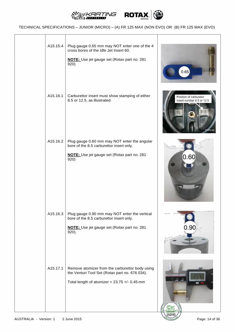
A15.15.4
Plug gauge 0.65 mm may NOT enter one of the 4
cross bores of the Idle Jet Insert 60.
NOTE: Use jet gauge set (Rotax part no. 281
920)
A15.16.1
Carburettor insert must show stamping of either
8.5 or 12.5, as illustrated.
A15.16.2
Plug gauge 0.60 mm may NOT enter the angular
bore of the 8.5 carburettor insert only.
NOTE: Use jet gauge set (Rotax part no. 281
920)
A15.16.3
Plug gauge 0.90 mm may NOT enter the vertical
bore of the 8.5 carburettor insert only.
NOTE: Use jet gauge set (Rotax part no. 281
920).
A15.17.1
Remove atomizer from the carburettor body using
the Venturi Tool Set (Rotax part no. 676 034).
Total length of atomizer = 23.75 +/- 0.45 mm

TECHNICAL SPECIFICATIONS – JUNIOR (MICRO) – (A) FR 125 MAX (NON EVO) OR (B) FR 125 MAX (EVO)
AUSTRALIA - Version: 1 2 June 2015 Page: 15 of 36
A15.17.2
Length of cylindrical part of atomizer
= 15.75 +/- 0.25 mm
A15.17.3
Dimension of cutaway of atomizer
= 6.00 +/- 0.15 mm
A15.17.4
Diameter of cross bore of atomizer
= 4.05 +/- 0.15 mm
A15.18
Optional carburettor plug screw marked “ROTAX”
(Rotax part no. 261 030) is legal to be used.
A15.19
The two vent fittings must be connected with the
original 180mm air vent hose.
(Rotax part no. 260 260).
Fuel Pump
A16.1
The original MIKUNI Fuel Pump (diaphragm type)
must be used.
Radiator
A17.1
A17.2
A17.3
Single aluminium radiator, as shown in
illustrations below.
Radiator must be mounted on the right side of the
engine, with all components as shown in the
respective illustrations.
No additional non-original cooling device is
allowed.

TECHNICAL SPECIFICATIONS – JUNIOR (MICRO) – (A) FR 125 MAX (NON EVO) OR (B) FR 125 MAX (EVO)
AUSTRALIA - Version: 1 2 June 2015 Page: 16 of 36
A17.4
A17.5
A17.6
The removal of the thermostat from the cylinder
head cover is accepted.
For versions 1, 2 and 3, tape can be applied
around the radiator. Tape may not be removed
from the radiator during operation on the track. All
other means of air flow control through the
radiator are prohibited, except for the plastic flap
on version 3.For version 3, the removal of the
original plastic flap is accepted.
Version 1
Cooling area: Height = 290 mm, Width = 133 mm
Thickness of radiator = 32 mm
Version 2
Cooling area: Height = 290 mm, Width = 133 mm
Thickness of radiator = 32 mm
Version 2 has two legal options to mount the
radiator to the retaining plate (see illustration).
Version 3
Cooling area: Height = 290 mm, Width = 138 mm
Thickness of radiator = 34 mm
The word “ROTAX” is stamped on the side of
radiator.
Radiator
Coolant
A18.1
A18.2
Glycol base or soluble oil coolants are prohibited.
Radiator coolant system must be fitted with a
catch tank of minimum 100mL capacity to retain
radiator coolant overflow, in accordance with
Technical Rules Chapter1 Rule 9(h)(iii) 2
TECHNICAL SPECIFICATIONS – JUNIOR (MICRO) – (A) FR 125 MAX (NON EVO) OR (B) FR 125 MAX (EVO)
AUSTRALIA - Version: 1 2 June 2015 Page: 17 of 36
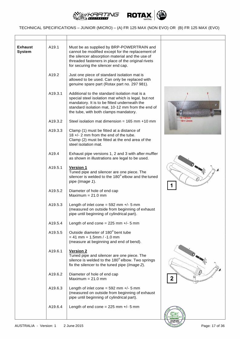
Exhaust
A19.1
Must be as supplied by BRP-POWERTRAIN and
System cannot be modified except for the replacement of
the silencer absorption material and the use of
threaded fasteners in place of the original rivets
for securing the silencer end cap.
A19.2 Just one piece of standard isolation mat is
allowed to be used. Can only be replaced with
genuine spare part (Rotax part no. 297 981).
A19.3.1 Additional to the standard isolation mat is a
special steel isolation mat which is legal, but not
mandatory. It is to be fitted underneath the
standard isolation mat, 10-12 mm from the end of
the tube, with both clamps mandatory.
A19.3.2 Steel isolation mat dimension = 165 mm +10 mm
A19.3.3 Clamp (1) must be fitted at a distance of
18 +/- 2 mm from the end of the tube.
Clamp (2) must be fitted at the end area of the
steel isolation mat.
A19.4 Exhaust pipe versions 1, 2 and 3 with after muffler
as shown in illustrations are legal to be used.
A19.5.1 Version 1
Tuned pipe and silencer are one piece. The
silencer is welded to the 180o
elbow and the tuned
pipe (Image 1).
A19.5.2 Diameter of hole of end cap
Maximum = 21.0 mm
A19.5.3 Length of inlet cone = 592 mm +/- 5 mm
(measured on outside from beginning of exhaust
pipe until beginning of cylindrical part).
A19.5.4 Length of end cone = 225 mm +/- 5 mm
A19.5.5 Outside diameter of 180o
bent tube
= 41 mm + 1.5mm / -1.0 mm
(measure at beginning and end of bend).
A19.6.1 Version 2
Tuned pipe and silencer are one piece. The
silence is welded to the 180o
elbow. Two springs
fix the silencer to the tuned pipe (Image 2).
A19.6.2 Diameter of hole of end cap
Maximum = 21.0 mm
A19.6.3 Length of inlet cone = 592 mm +/- 5 mm
(measured on outside from beginning of exhaust
pipe until beginning of cylindrical part).
A19.6.4 Length of end cone = 225 mm +/- 5 mm
TECHNICAL SPECIFICATIONS – JUNIOR (MICRO) – (A) FR 125 MAX (NON EVO) OR (B) FR 125 MAX (EVO)
AUSTRALIA - Version: 1 2 June 2015 Page: 18 of 36
A19.6.5
Outside diameter of 180o
bent tube
= 41 mm + 1.5mm / -1.0 mm
(measure at beginning and end of bend).
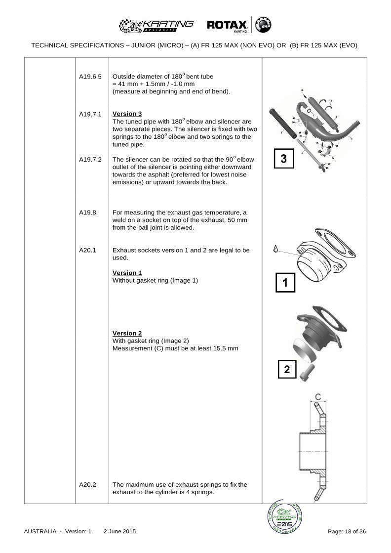
A19.7.1
Version 3
The tuned pipe with 180o
elbow and silencer are
two separate pieces. The silencer is fixed with two
springs to the 180o
elbow and two springs to the
tuned pipe.
A19.7.2 The silencer can be rotated so that the 90o
elbow
outlet of the silencer is pointing either downward
towards the asphalt (preferred for lowest noise
emissions) or upward towards the back.
A19.8
For measuring the exhaust gas temperature, a
weld on a socket on top of the exhaust, 50 mm
from the ball joint is allowed.
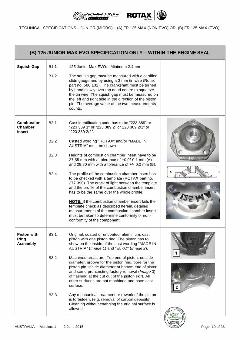
A20.1
Exhaust sockets version 1 and 2 are legal to be
used.
Version 1
Without gasket ring (Image 1)
Version 2
With gasket ring (Image 2)
Measurement (C) must be at least 15.5 mm
A20.2
The maximum use of exhaust springs to fix the
exhaust to the cylinder is 4 springs.
TECHNICAL SPECIFICATIONS – JUNIOR (MICRO) – (A) FR 125 MAX (NON EVO) OR (B) FR 125 MAX (EVO)
AUSTRALIA - Version: 1 2 June 2015 Page: 19 of 36
(B) 125 JUNIOR MAX EVO SPECIFICATION ONLY – WITHIN THE ENGINE SEAL
Squish Gap
B1.1
B1.2
125 Junior Max EVO: Minimum 2.4mm
The squish gap must be measured with a certified
slide gauge and by using a 3 mm tin wire (Rotax
part no. 580 132). The crankshaft must be turned
by hand slowly over top dead centre to squeeze
the tin wire. The squish gap must be measured on
the left and right side in the direction of the piston
pin. The average value of the two measurements
counts.
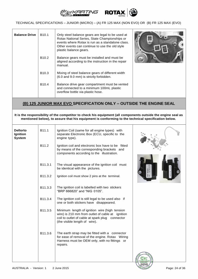
Combustion
B2.1
Cast identification code has to be "223 389" or
Chamber "223 389 1" or "223 389 2" or 223 389 2/1" or
Insert “223 389 2/2”.
B2.2 Casted wording "ROTAX" and/or "MADE IN
AUSTRIA" must be shown
B2.3 Heights of combustion chamber insert have to be
27.55 mm with a tolerance of +0.0/-0,1 mm (A)
and 28.80 mm with a tolerance of +/- 0.2 mm (B).
B2.4 The profile of the combustion chamber insert has
to be checked with a template (ROTAX part no.
277 390). The crack of light between the template
and the profile of the combustion chamber insert
has to be the same over the whole profile.
NOTE: If the combustion chamber insert fails the
template check as described herein, detailed
measurements of the combustion chamber insert
must be taken to determine conformity or non-
conformity of the component.
Piston with
Ring
Assembly
B3.1
B3.2
B3.3
Original, coated or uncoated, aluminium, cast
piston with one piston ring. The piston has to
show on the inside of the cast wording "MADE IN
AUSTRIA" (Image 1) and "ELKO" (Image 2).
Machined areas are: Top end of piston, outside
diameter, groove for the piston ring, bore for the
piston pin, inside diameter at bottom end of piston
and some pre-existing factory removal (Image 3)
of flashing at the cut out of the piston skirt. All
other surfaces are not machined and have cast
surface.
Any mechanical treatment or rework of the piston
is forbidden, (e.g. removal of carbon deposits).
Cleaning without changing the original surface is
allowed.

TECHNICAL SPECIFICATIONS – JUNIOR (MICRO) – (A) FR 125 MAX (NON EVO) OR (B) FR 125 MAX (EVO)
AUSTRALIA - Version: 1 2 June 2015 Page: 20 of 36
B3.4
B3.5
Original, magnetic, rectangular piston ring.
Ring height: 0,98 +/- 0,02 mm.
Piston ring is marked either with "ROTAX 215
547" or "ROTAX 215 548".
Piston Pin
(Gudgeon
Pin)
B4.1
B4.2
B4.3
Piston pin is made out of magnetic steel.
Dimensions must be according to the drawing.
The minimum weight of the piston pin must not be
lower than 32.10 grams.
Cylinder
B5.1
Light-alloy-cylinder with GILNISIL-plating.
Any re-plating of cylinder is not allowed.
B5.2 Cylinder with one main exhaust port and no
exhaust valve.
B5.3 Maximum bore of cylinder = 54,035mm
(measured 10 mm above the exhaust port).
B5.4 Cylinder has to be marked with the "ROTAX" logo
(see pictures).
B5.5.1 Cylinder has to be marked either identification
code 223 998, 223 994 (see pictures).
B5.5.2
Cylinder 223 999 is outlawed.
B5.6
Height of cylinder has to be 87mm -0.05/+0.1mm
(measured with a digital calliper).

TECHNICAL SPECIFICATIONS – JUNIOR (MICRO) – (A) FR 125 MAX (NON EVO) OR (B) FR 125 MAX (EVO)
AUSTRALIA - Version: 1 2 June 2015 Page: 21 of 36
B5.7.1
All transfer ports and passages have cast finish
surface except some removal (done by the
manufacturer) of cast burr at the inlet passage,
exhaust port and passages. All ports have
chamfered edges to prevent ring snagging. Any
additional machining is not permitted. The top
edge of exhaust port may show some pre-existing
machining from the manufacturer. The sealing
flange for the exhaust socket may show signs of
machining from the manufacturer.
B5.7.2
All ports have chamfered edges. Any additional
machining is not permitted.
B5.7.3
On cylinders marked 223 994 the upper edge of
the central boost port may show factory
machining.
B5.7.4
The sealing flange for the exhaust socket may
show either cast finish or machined surface.
Machined surface can be either flat or show a
circular sealing bump.
B5.7.5
The top edge of the exhaust port may show either
just a cast finish surface (Image1) or signs of
CNC machining (Image2) or signs of CNC
machining in combination with signs of manual
grinding (Image 3). The exhaust port may show
partial manual grinding done by the manufacturer
to eliminate minor casting defects and/or to
eliminate the NIKASIL burr at the end of the
NIKASIL plating (Image 3).

TECHNICAL SPECIFICATIONS – JUNIOR (MICRO) – (A) FR 125 MAX (NON EVO) OR (B) FR 125 MAX (EVO)
AUSTRALIA - Version: 1 2 June 2015 Page: 22 of 36
B5.7.6
B5.8
On cylinders marked 223 994 the exhaust port
may show factory machining all around.
FR 125 Junior Max: Cylinder 223 998 = 0.90 mm
Cylinder 223 994 = 1.10 mm
The "exhaust port timing" (distance from the top of
the cylinder to the top of the exhaust port) has to
be checked by means of the template (Rotax part
no. 277 397).
Insert the template into the cylinder, so that the
template is touching the cylinder wall and that the
finger of the template is located in the middle of
the exhaust port (highest point).
Move the template upwards, until the finger is
touching the top edge of the exhaust port. Insert a
filler gauge between the top of the cylinder and
the template. It must not be possible to fit the
feeler gauge specified below.
NOTE: Take care to use the corresponding gauge
of the template (JUN, MAX or DD2) for the
respective cylinder.
Inlet System
B6.1
B6.2
B6.3
B6.4
Inlet manifold is marked with the name "ROTAX"
and the identification code “267 915”
Some factory flash removal may be present at the
conjunction of the inside contour and the
carburettor stop mounting face. This is a manual
trimming operation consisting of a small corner
break of less than 3 mm in width. No additional
grinding or machining is permitted.
The reed valve assy. is equipped with 2 petal
stops and 2 reeds, each having 3 petals.
The thickness of the reeds is 0.6 mm +/- 0.10
mm.

TECHNICAL SPECIFICATIONS – JUNIOR (MICRO) – (A) FR 125 MAX (NON EVO) OR (B) FR 125 MAX (EVO)
AUSTRALIA - Version: 1 2 June 2015 Page: 23 of 36
Crankshaft
B7.1
B7.2
B7.3
B7.4
B7.5
Stroke 54.5 mm +/-0,1 mm
Con rod has to show forged numbers "213",
"365", "367" or “362” on shaft.
Shafts of con rods "213", "365" and "367" are not
machined and are copper plated (Image 1). Shaft
of con rod “362” is not copper plated and
blank/grey (Image 2).
Grinding or polishing of shaft of con rod is not
permitted.
Effective from 1st June 2012, crankshaft main
bearing 6206 from FAG only is allowed for
Rotax National Series, State Championships or
events where Rotax is run as a standalone class
(must be marked with code 579165BA or
Z-579165.11.KL). This does not apply to
Restricted TAG, TAG & Sportsman style
classes.
Balance Shaft
B8.1
B8.2
B8.3
B8.4
B8.5
Balance shaft and balance gears must be
installed
Configurations of part no. 237 949 (equal with 237
948) only is legal.
Surface (1) is not machined and must show cast
surface.
Measurement from centre of balance shaft to
outer diameter of fly weight of balance shaft at
defined length must not be lower than specified.
The minimum weight of the dry balance shaft
must not be lower than: 255 grams for balance
shaft Rotax part no. 237 949 (equal with 237 948).
Crankcase
B9.1
B9.2
As supplied by the manufacturer. No grinding or
polishing is permitted in the two main transfer
passages as well as in the crank area.
Uncoated as well as black coated crankcases are
legal to be used.
TECHNICAL SPECIFICATIONS – JUNIOR (MICRO) – (A) FR 125 MAX (NON EVO) OR (B) FR 125 MAX (EVO)
AUSTRALIA - Version: 1 2 June 2015 Page: 24 of 36
Balance Drive
B10.1
B10.2
B10.3
B10.4
Only steel balance gears are legal to be used at
Rotax National Series, State Championships or
events where Rotax is run as a standalone class.
Other events can continue to use the old style
plastic balance gears.
Balance gears must be installed and must be
aligned according to the instruction in the repair
manual.
Mixing of steel balance gears of different width
(6.0 and 9.0 mm) is strictly forbidden.
Balance drive gear compartment must be vented
and connected to a minimum 100mL plastic
overflow bottle via plastic hose.
(B) 125 JUNIOR MAX EVO SPECIFICATION ONLY – OUTSIDE THE ENGINE SEAL
It is the responsibility of the competitor to check his equipment (all components outside the engine seal as
mentioned below), to assure that his equipment is conforming to the technical specification below.
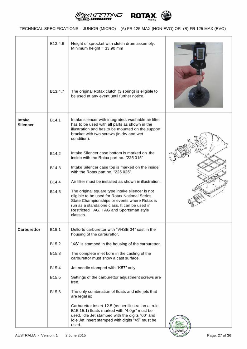
Dellorto
B11.1
Ignition Coil (same for all engine types) with
Ignition separate Electronic Box (ECU, specific to the
System engine type).
B11.2 Ignition coil and electronic box have to be fitted
by means of the corresponding brackets and
components according to the illustration.
B11.3.1
The visual appearance of the ignition coil must
be identical with the pictures.
B11.3.2 Ignition coil must show 2 pins at the terminal.
B11.3.3
The ignition coil is labelled with two stickers
“BRP 666820” and “NIG 0105”.
B11.3.4 The ignition coil is still legal to be used also if
one or both stickers have disappeared.
B11.3.5 Minimum length of ignition wire (high tension
wire) is 210 mm from outlet of cable at ignition
coil to outlet of cable at spark plug connector
(the visible length of wire).
B11.3.6
The earth strap may be fitted with a connector
for ease of removal of the engine. Rotax Wiring
Harness must be OEM only, with no fittings or
repairs.

TECHNICAL SPECIFICATIONS – JUNIOR (MICRO) – (A) FR 125 MAX (NON EVO) OR (B) FR 125 MAX (EVO)
AUSTRALIA - Version: 1 2 June 2015 Page: 25 of 36
B11.4
B11.5
B11.6.1
B11.6.2
The pick-up must be marked with the numbers
029600-0710, followed by a variable production
code in the 2nd line (Image 3).
HINT: In case of doubt, an easy check is to
place a steel ball (3-5 mm in diameter) on the
pick-up (engine side). The steel ball must stay
in the center of the pick-up surface.
Spark plug cap must be marked with
“NGK TB05EMA” (Image 4).
The electronic boxes are labelled with stickers
(specific to the engine type) and are still legal to
be used also if the sticker has disappeared.
125 Junior Max EVO: “666812” and
“125 Junior MAX evo”
The electronic box has to be checked with the
ECU tester (Rotax part no. 276 230) according
to the following procedure:
1. Disconnect engine cable harness from
electronic box.
2. Connect ECU tester cable harness to
electronic box.
3. Connect energy cable of ECU tester
cable harness with the chargin
connector of engine cable harness.
4. The ECU tester will automatically detect
the type of the ECU and will start a
check program for the ignition timing
and the timing for the exhaust valve.
5. The ECU tester must show the
following results for 125 Junior Max
EVO:
“ECU TEST OK”
“125 Junior MAX evo”
Centrifugal
Clutch
B13.1
B13.2.1
Dry centrifugal clutch with engagement maximum
at 4,000 r.p.m.
This means that the kart must start to move
before the engine speed reaches
4,000 r.p.m.
There are 2 versions of the steel clutch (Image 1)
and both are legal to be used. The older version
can be either untreated or nitrated configuration.
Needle cage bearing 15x19x17 (Rotax part no.
632 415) must be fitted for 12, 13 and 14 tooth
sprockets. Plain bearing 15x17x20 (Rotax part no.
233 855) must be fitted for 11 tooth sprockets.
(Image 2)

TECHNICAL SPECIFICATIONS – JUNIOR (MICRO) – (A) FR 125 MAX (NON EVO) OR (B) FR 125 MAX (EVO)
AUSTRALIA - Version: 1 2 June 2015 Page: 26 of 36
B13.2.2
O-Ring 12x2.5 (Rotax part no. 950 815) must be
fitted and must assure an appropriate sealing
between the clutch drum and the needle/plain
bearing.
B13.3
No extra lubrication or substance is allowed inside
the clutch drum, in addition to the grease that
originates from lubrication of the needle cage
bearing, and enters the clutch area.
See (Images) showing worst case scenario of
when grease exits the needle bearing area, even
with the O-Ring installed. Only the fixation nut and
the inside of the drum show signs of grease. The
running surface of the drum is completely dry.
When the plain bearing for 11 tooth sprockets is
used, the clutch area must be absolutely free of
grease or any additional substance.
B13.4.1
Steel clutch (both versions) and clutch drum must
be within the following specifications:
B13.4.2
Height of clutch: Minimum = 11.45 mm
B13.4.3
Thickness of clutch: Minimum = 24.10 mm
NOTE: Measurement has to be done at the 3
open ends of the clutch shoes, 5 – 10 mm from
the machined groove (all clutch shoes must be
completely closed at measurement, with no gap
showing).
B13.4.4
Outer diameter of clutch drum:
Minimum diameter = 89.50 mm
NOTE: Diameter has to be measured with a
sliding calliper, just beside the radius from the
shoulder (not at the open end of the clutch drum).
B13.4.5
Inner diameter of clutch drum:
Maximum diameter = 84.90 mm
NOTE: The inner diameter has to be measured
with a sliding calliper. The measrement has to be
done in the middle of the clutch drum (in the
contact area of the clutch drum).
TECHNICAL SPECIFICATIONS – JUNIOR (MICRO) – (A) FR 125 MAX (NON EVO) OR (B) FR 125 MAX (EVO)
AUSTRALIA - Version: 1 2 June 2015 Page: 27 of 36
B13.4.6
B13.4.7
Height of sprocket with clutch drum assembly:
Minimum height = 33.90 mm
The original Rotax clutch (3 spring) is eligible to
be used at any event until further notice.
Intake
Silencer
B14.1
B14.2
B14.3
B14.4
B14.5
Intake silencer with integrated, washable air filter
has to be used with all parts as shown in the
illustration and has to be mounted on the support
bracket with two screws (in dry and wet
condition).
Intake Silencer case bottom is marked on .the
inside with the Rotax part no. “225 015”
Intake Silencer case top is marked on the inside
with the Rotax part no. “225 025”.
Air filter must be installed as shown in illustration.
The original square type intake silencer is not
eligible to be used for Rotax National Series,
State Championships or events where Rotax is
run as a standalone class. It can be used in
Restricted TAG, TAG and Sportsman style
classes.
Carburettor
B15.1
B15.2
B15.3
B15.4
B15.5
B15.6
Dellorto carburettor with “VHSB 34” cast in the
housing of the carburettor.
“XS” is stamped in the housing of the carburettor.
The complete inlet bore in the casting of the
carburettor must show a cast surface.
Jet needle stamped with “K57” only.
Settings of the carburettor adjustment screws are
free.
The only combination of floats and idle jets that
are legal is:
Carburettor insert 12.5 (as per illustration at rule
B15.15.1) floats marked with “4.0gr” must be
used. Idle Jet stamped with the digits “60” and
Idle Jet Insert stamped with digits “45” must be
used.

TECHNICAL SPECIFICATIONS – JUNIOR (MICRO) – (A) FR 125 MAX (NON EVO) OR (B) FR 125 MAX (EVO)
AUSTRALIA - Version: 1 2 June 2015 Page: 28 of 36
B15.7
All jets must be correctly seated and securely
fitted.
B15.8 A minimum required size of Main Jet may be
determined for each race event by a
“Supplementary Regulation”.
B15.9
Needle Valve assembly stamped with the digits
“150” (Image 1)
B15.10 Needle of Needle Valve marked with diamond
symbol “INC” only (Image 2).
B15.11
Start Jet is stamped with the digits “60”.
B15.12.1 Needle Jet is stamped with “DP 267”.
B15.12.2
Total length of Needle Jet = 51.00 +/- 0.3 mm
B15.12.3
Length of bottom section of Needle Jet
= 33.0 +/- 0.2 mm
B15.13.1
Idle Jet 60 and Idle Jet Insert 45 must be used
with carburettor insert stamped 12.5, as per
illustration at rule B15.15.1.
B15.13.2
Plug gauge 0.65 mm may NOT enter the bore of
the Idle Jet 60.
NOTE: Use jet gauge set (Rotax part no. 281
920)
B15.13.3
Plug gauge 0.55 mm may NOT enter the bore of
the Idle Jet Insert 45.
NOTE: Use jet gauge set (Rotax part no. 281
920)

TECHNICAL SPECIFICATIONS – JUNIOR (MICRO) – (A) FR 125 MAX (NON EVO) OR (B) FR 125 MAX (EVO)
AUSTRALIA - Version: 1 2 June 2015 Page: 29 of 36
B15.13.4
Plug gauge 0.55 mm may NOT enter one of the 4
cross bores of the Idle Jet Insert 45.
NOTE: Use jet gauge set (Rotax part no. 281
920)
B15.14
Carburettor insert must show stamping of 12.5, as
illustrated.
B15.15.1
Remove atomizer from the carburettor body using
the Venturi Tool Set (Rotax part no. 676 034).
Total length of atomizer = 23.75 +/- 0.45 mm
B15.15.2
Length of cylindrical part of atomizer
= 15.75 +/- 0.25 mm
B15.15.3
Dimension of cutaway of atomizer
= 5.75 +/- 0.15 mm

TECHNICAL SPECIFICATIONS – JUNIOR (MICRO) – (A) FR 125 MAX (NON EVO) OR (B) FR 125 MAX (EVO)
AUSTRALIA - Version: 1 2 June 2015 Page: 30 of 36
B15.15.4
B15.16.1
B15.16.2
Diameter of cross bore of atomizer
= 5.00 +/- 0.15 mm
Optional carburettor plug screw marked “ROTAX”
(Rotax part no. 261 030) is legal to be used.
The two vent fittings must be connected with the
original 180mm air vent hose.
(Rotax part no. 260 260).
Fuel Pump
B16.1
The original MIKUNI Fuel Pump (diaphragm type)
must be used.
Radiator
B17.1
B17.2
B17.3
B17.4
B17.5
B17.6
Single aluminium radiator, as shown in
illustrations below.
Radiator must be mounted on the right side of the
engine, with all components as shown in the
respective illustrations.
No additional non-original cooling device is
allowed.
The removal of the thermostat from the cylinder
head cover is accepted.
For versions 1, 2 and 3, tape can be applied
around the radiator. Tape may not be removed
from the radiator during operation on the track. All
other means of air flow control through the
radiator are prohibited, except for the plastic flap
on version 3.For version 3, the removal of the
original plastic flap is accepted.
Version 1
Cooling area: Height = 290 mm, Width = 133 mm
Thickness of radiator = 32 mm

TECHNICAL SPECIFICATIONS – JUNIOR (MICRO) – (A) FR 125 MAX (NON EVO) OR (B) FR 125 MAX (EVO)
AUSTRALIA - Version: 1 2 June 2015 Page: 31 of 36
Version 2
Cooling area: Height = 290 mm, Width = 133 mm
Thickness of radiator = 32 mm
Version 2 has two legal options to mount the
radiator to the retaining plate (see illustration).
Version 3
Cooling area: Height = 290 mm, Width = 138 mm
Thickness of radiator = 34 mm
The word “ROTAX” is stamped on the side of
radiator.
Radiator
Coolant
B18.1
B18.2
Glycol base or soluble oil coolants are prohibited.
Radiator coolant system must be fitted with a
catch tank of minimum 100mL capacity to retain
radiator coolant overflow, in accordance with
Technical Rules Chapter1 Rule 9(h)(iii) 2
Exhaust
B19.1
Must be as supplied by BRP-POWERTRAIN and
System cannot be modified except for the replacement of
the silencer absorption material and the use of
threaded fasteners in place of the original rivets
for securing the silencer end cap.
B19.2 Just one piece of standard isolation mat is
allowed to be used. Can only be replaced with
genuine spare part (Rotax part no. 297 981).
B19.3.1 Additional to the standard isolation mat is a
special steel isolation mat which is legal, but not
mandatory. It is to be fitted underneath the
standard isolation mat, 10-12 mm from the end of
the tube, with both clamps mandatory.
B19.3.2 Steel isolation mat dimension = 165 mm +10 mm
B19.3.3 Clamp (1) must be fitted at a distance of
18 +/- 2 mm from the end of the tube.
Clamp (2) must be fitted at the end area of the
steel isolation mat.
TECHNICAL SPECIFICATIONS – JUNIOR (MICRO) – (A) FR 125 MAX (NON EVO) OR (B) FR 125 MAX (EVO)
AUSTRALIA - Version: 1 2 June 2015 Page: 32 of 36
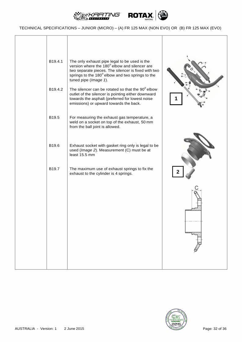
B19.4.1
The only exhaust pipe legal to be used is the
version where the 180o
elbow and silencer are
1
two separate pieces. The silencer is fixed with two
springs to the 180o
elbow and two springs to the
tuned pipe (Image 1).
B19.4.2 The silencer can be rotated so that the 90o
elbow
outlet of the silencer is pointing either downward
towards the asphalt (preferred for lowest noise
emissions) or upward towards the back.
B19.5
For measuring the exhaust gas temperature, a
weld on a socket on top of the exhaust, 50 mm from the ball joint is allowed.
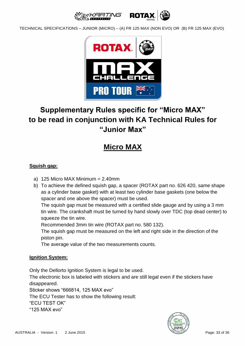
B19.6
Exhaust socket with gasket ring only is legal to be
used (Image 2). Measurement (C) must be at least 15.5 mm
B19.7
The maximum use of exhaust springs to fix the
exhaust to the cylinder is 4 springs.
2
TECHNICAL SPECIFICATIONS – JUNIOR (MICRO) – (A) FR 125 MAX (NON EVO) OR (B) FR 125 MAX (EVO)
AUSTRALIA - Version: 1 2 June 2015 Page: 33 of 36
Supplementary Rules specific for “Micro MAX”
to be read in conjunction with KA Technical Rules for
“Junior Max”
Micro MAX
Squish gap:
a) 125 Micro MAX Minimum = 2.40mm
b) To achieve the defined squish gap, a spacer (ROTAX part no. 626 420, same shape
as a cylinder base gasket) with at least two cylinder base gaskets (one below the
spacer and one above the spacer) must be used.
The squish gap must be measured with a certified slide gauge and by using a 3 mm
tin wire. The crankshaft must be turned by hand slowly over TDC (top dead center) to
squeeze the tin wire.
Recommended 3mm tin wire (ROTAX part no. 580 132).
The squish gap must be measured on the left and right side in the direction of the
piston pin.
The average value of the two measurements counts.
Ignition System:
Only the Dellorto Ignition System is legal to be used.
The electronic box is labeled with stickers and are still legal even if the stickers have
disappeared.
Sticker shows “666814, 125 MAX evo”
The ECU Tester has to show the following result:
“ECU TEST OK”
“125 MAX evo”
TECHNICAL SPECIFICATIONS – JUNIOR (MICRO) – (A) FR 125 MAX (NON EVO) OR (B) FR 125 MAX (EVO)
AUSTRALIA - Version: 1 2 June 2015 Page: 34 of 36
Radiator:
a) A specific "Micro MAX" radiator (ROTAX part no. 295 924 or 295 923) must be used
instead of the original radiator.
b) Radiator must be mounted with all components similar to the illustration version 2 or
3 for the 125 MAX engine. (see item
9.7.8 of the technical regulations 2014).
c) Cooling area:
height = 280 - 300 mm
width = 58 - 62 mm
thickness of radiator = 30 - 34 mm
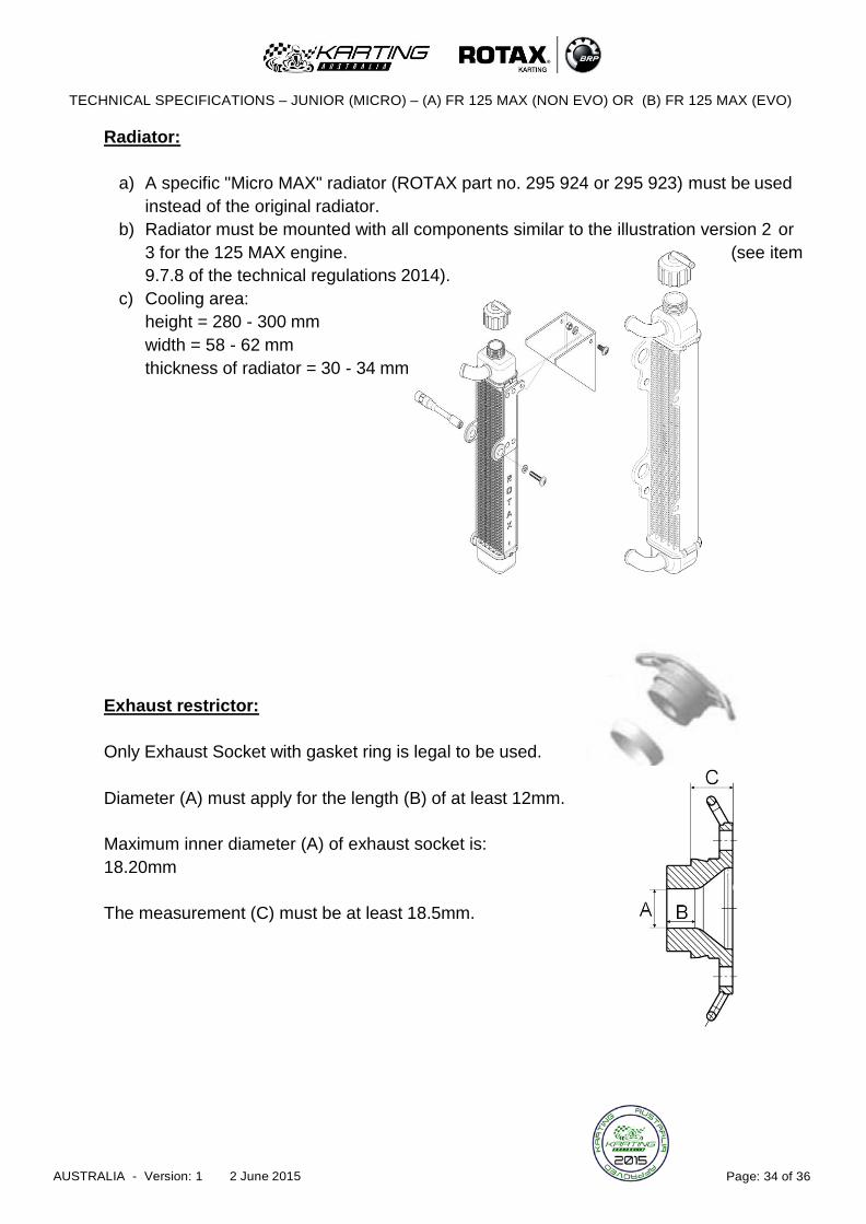
Exhaust restrictor:
Only Exhaust Socket with gasket ring is legal to be used.
Diameter (A) must apply for the length (B) of at least 12mm.
Maximum inner diameter (A) of exhaust socket is:
18.20mm
The measurement (C) must be at least 18.5mm.

TECHNICAL SPECIFICATIONS – JUNIOR (MICRO) – (A) FR 125 MAX (NON EVO) OR (B) FR 125 MAX (EVO)
AUSTRALIA - Version: 1 2 June 2015 Page: 35 of 36
Exhaust system:
a) The specific "Micro MAX" exhaust system must be used instead of the original
exhaust system (see illustration below).
b) The inner diameter of the elbow outlet at the silencer end cover has to have a
minimum measurement of 21mm.
Cylinder:
a) The cylinder (ROTAX part no. 223 994) must be cast with two “Letters” within a circle on the drive side, and not a number.
b) Any combination of two “Letters” is acceptable. Photo is for illustration purposes only.