Embed Size (px)
Citation preview
IEEE TRANSACTIONS ON MAGNETICS, VOL. XX, NO. XX, XXXXXXXXX XXXX 1
Rotational Single Sheet Tester for Multiaxial Magneto-MechanicalEffects in Steel Sheets
U. Aydin1, F. Martin1, P. Rasilo1,2, A. Belahcen1, A. Haavisto1, D. Singh1, L. Daniel3, and A. Arkkio1
1Aalto University, Department of Electrical Engineering and Automation, FI-00076, Espoo, Finland2Tampere University of Technology, Laboratory of Electrical Energy Engineering, FI-33101, Tampere, Finland
3GeePs | Group of electrical engineering - Paris, UMR CNRS 8507, CentraleSupelec, Univ. Paris-Sud, Universite Paris-Saclay,Sorbonne Universites, UPMC Univ Paris 06, 3 & 11 rue Joliot-Curie, Plateau de Moulon 91192 Gif-sur-Yvette Cedex, France
A detailed design of a new rotational single sheet tester device which allows comprehensive multiaxial magneto-mechanical analysisof ferromagnetic sheets is proposed. The challenges which arose during the mechanical and magnetic design phases are addressed.The applicability of the device is tested by performing magneto-mechanical measurements on a M400-50A electrical steel sheet.Results under several multiaxial magneto-mechanical loadings with circular and alternating magnetic flux densities are reported. Itis shown that the effect of multiaxial stress on the iron losses can be much more significant than that of uniaxial stress.
Index Terms—Core losses, iron losses, magneto-mechanical effects, multiaxial stress, single sheet tester
I. INTRODUCTION
FERROMAGNETIC materials are widely used in manyelectromagnetic applications such as electrical machines
and transducers. In most of these devices, the material issubject to multiaxial mechanical stresses which are causedby manufacturing processes or operating conditions [1]–[6].In addition, the orientation of the magnetic field and stressmay vary in the material, since, for instance, in 3-phasetransformers and rotating electrical machines both rotatingand alternating flux conditions occur. On the other hand, itis known that the mechanical stress has strong influence onthe magnetic properties of ferromagnetic materials [7]–[22].Previous studies have shown that the performance of electricalmachines is affected significantly by the complex multiaxialmagneto-mechanical loadings that occur in the material [23]–[29]. Therefore, it is evident that characterization of themagnetic properties of electrical steel sheets under multiaxialloadings is needed in order to design more efficient devices.Especially the effect of stress on core losses should be studiedin detail.
Single sheet testers are widely used for magneto-mechanicalcharacterization of electrical steel sheets. For instance, in[7]–[11] the magnetic behavior of electrical steel sheets isstudied under uniaxial stress applied parallel to the alternatingmagnetic field. In [12]–[16] effect of uniaxial stress is studied
Manuscript received xxxxxxxxx xx, xxxx; revised xxxxxxxxx xx, xxxxand xxxxxxxxx xx, xxxx; accepted xxxxxxxxx xx. Date of publicationxxxxxxxxx xx; date of current version xxxxxxxxx xx. (Dates will be insertedby IEEE; “published” is the date the accepted preprint is posted on IEEEXplorer; “current version” is the date the typeset version is posted onXplorer). Corresponding author: U. Aydin (e-mail: [email protected]). Ifsome authors contributed equally, write here, “F. A. Author and S. B. Authorcontributed equally.” IEEE TRANSACTIONS ON MAGNETICS discouragescourtesy authorship; please use the Acknowledgment section to thank yourcolleagues for routine contributions.
Color versions of one or more of the figures in this paper are availableonline at http://ieeexplore.ieee.org.
Digital Object Identifier (inserted by IEEE).
under rotating flux conditions. Biaxial magneto-mechanicaltests have been performed in [17]–[20] using cross-shapedspecimens under alternating flux conditions. Even though,these biaxial tests can provide deeper understanding of multi-axial magneto-mechanical behavior compared to uniaxial tests,they do not provide control for arbitrary flux waveform andin-plane stress tensors in the material which occur in electricalmachines. A device which has the ability to apply an arbitraryin-plane stress tensor and flux density, using a specimenthat has eight legs, is reported in [21], [22]. They reportedmagneto-mechanical experimental results under up to 0.6 Tpeak induction and 30 MPa maximum stress levels.
In this paper a rotational single sheet tester (RSST) devicewhich provides a possibility of comprehensive analysis of mul-tiaxial magneto-mechanical behavior of ferromagnetic sheetsis introduced. Details of the design phases are explained andchallenges which arose during the design phases are addressed.The measurement system and control procedures for stressand flux density waveform are detailed. Magneto-mechanicalmeasurements under circular and alternating flux densities upto 1.2 T and under ±30 MPa multiaxial in-plane stresses ona M400-50A non-oriented electrical steel sheet are performedand reported.
II. DESIGN OF THE ROTATIONAL SINGLE SHEET TESTER
In order to analyze the effect of mechanical stress onthe magnetic behavior of the material accurately, uniformstress and magnetic field distributions need to be createdin an area large enough for performing the measurements.Therefore, the aim was to design a sample geometry thatfulfills these requirements and which allows arbitrary stressand magnetization control.
The flat geometry of the electrical steel sheets allows in-plane study of the geometry which means the stress tensorσ has three variables to be controlled and the tensor can be
0018-9464 c© 2015 IEEE. Personal use is permitted, but republication/redistribution requires IEEE permission.See http://www.ieee.org/publications standards/publications/rights/index.html for more information. (Inserted by IEEE.)

IEEE TRANSACTIONS ON MAGNETICS, VOL. XX, NO. XX, XXXXXXXXX XXXX 2
Fig. 1. Sample geometry.
written as σ =[σxx σyy σxy
]Tin Voigt notation. Previously
we have shown in [30] that it is possible to control each com-ponent of σ using a six-leg sample geometry. The calculationwill be repeated here for the sake of clarity. Take the samplegeometry shown in Fig. 1 and assume an isotropic linear elasticmaterial. In order to have the desired in-plane stress tensor atthe measurement area which is located at the central regionof the sample, the required mechanical loadings for each legpair can be calculated by constructing a linear set of equationsusing the following procedure.
1. An initial mechanical loading pini is applied only to theL0 leg pair and an in-plane stress tensor in the central area isobtained as
σ0◦ =
[σ0◦xx σ0◦xyσ0◦xy σ0◦yy
](1)
2. In order to get reference stress tensors at the centralregion for legs L60 and L120, a coordinate transformation isapplied to (1) using coordinate transformation matrix Qθ forangles θ = 60◦ and θ = 120◦ as
Qθ =[
cos θ sin θ-sin θ cos θ
](2)
σθ = Qθ · σ0◦ · QTθ (3)
3. Let us define the desired in-plane stress tensor in thecentral region as σref and required mechanical loadings to beapplied to L0, L60, L120 leg pairs as p0◦ , p60◦ and p120◦ ,respectively. Since linear elasticity is assumed a linear relationbetween p0◦ , p60◦ , p120◦ and pini can be used to set thefollowing equation
σref = σ0◦ ·p0◦
pini+ σ60◦ ·
p60◦
pini+ σ120◦ ·
p120◦
pini. (4)
Equation (4) can be written in a more consistent form as
σref,xxσref,yyσref,xy
=1
pini·
σ0◦xx σ60◦xx σ120◦xxσ0◦yy σ60◦yy σ120◦yyσ0◦xy σ60◦xy σ120◦xy
· p0◦
p60◦
p120◦
. (5)
Solution of this system for p0◦ , p60◦ and p120◦ yields therequired loadings to be applied to the leg pairs L0, L60, L120
in order to obtain the arbitrary in-plane stress tensor σref at thecentral region. Mechanical stresses should be applied to eachleg pair independently to ensure the homogeneity of stressdistribution. A negligible displacement in the central point ofthe sample is preferred so that six actuators are needed. It isworth mentioning that the same principle can be applied toobtain an in-plane strain tensor as well. The above calculationwas given in order to demonstrate that it is possible to obtainan arbitrary in-plane stress tensor using six-legs geometry byassuming an isotropic material. In practice, having an isotropicmaterial might not be possible. Therefore, this procedure willnot be used directly for the control of the mechanical actuators.
The tips of the legs in the sample geometry were designedhaving T-shapes to ease the clamping of the sample for stressapplication. The maximum magnitude of the stress that can beapplied to the legs is limited by the buckling of the sampleunder compressive loading. To maximize the compressivestress without facing the buckling issue, the ratio of the samplelength to its thickness should be as low as possible. Onthe other hand, the sample should be long enough to obtainlow values of demagnetizing factor. In addition, the narrowerwidths close to the central region in the sample geometryhelp obtaining higher mechanical stress in the measurementarea compared to the sample geometry without these regions,when the same mechanical loadings are applied to the tips ofthe legs.
In single sheet testers which adopt magnetization yokes,the systems to magnetize the specimen can be categorizedinto vertical and horizontal magnetization systems dependingon the penetration angle of the flux to the sample. In thevertical and horizontal magnetization systems, the penetrationdirection of the flux to the specimen is perpendicular andparallel to the specimen plane, respectively. In the presentwork a horizontal magnetization system is adopted due to itsadvantages over vertical systems. For instance, formation ofeddy currents where the flux penetrates the sample can beminimized using horizontal yoke systems. This helps reducingthe angular bending of the flux. Using a correct horizontalyoke geometry can also reduce the stray fluxes between theyokes and the sample greatly [31], [32]. Another advantage ofa horizontal magnetizing system is that the sample installationcan be considerably simpler since the magnetizing system isusually fixed. Six magnetization coils which are wound aroundmagnetizing yokes are placed between each leg, which meansthat the space for the magnetization system should be takeninto account when determining the sample diameter.
All these factors were considered to determine the samplediameter. Before finalizing the sample geometry, in order toensure the stress and magnetic field homogeneity at the centralregion, several sample geometries were simulated using finiteelement method. For simulating the mechanical part, 2D planestress approximation was used and several mechanical loadingconfigurations were simulated. For simulating the magneticpart, 2D approximation which assumes the same thickness forall the geometry, leads to inaccurate field calculation resultssince in reality, the magnetizing yokes are much thicker than

IEEE TRANSACTIONS ON MAGNETICS, VOL. XX, NO. XX, XXXXXXXXX XXXX 3
the sample. For this reason, the magnetic part was simulated byusing 3D magnetic vector potential formulation. Consideringthe simulation results on several sample geometries, the ge-ometry shown in Fig. 1 has resulted in sufficient homogeneityof the magnetic flux density and stress distributions. In ameasurement area of 20×20 mm2 the maximum relativestandard deviation of the stress was found to be 4.38 %. Forthe magnetic flux density this value was 2.74% and obtainedat the instant shown in Fig. 2.
It is now established that using a sample geometry asshown in Fig. 1, it is possible to obtain any in-plane stresstensor with negligible displacement in the measurement area.In addition, with proper control the sample can be magnetizedwith arbitrary magnetization waveform in the measurementarea. This means that, any orientation between in-plane stressand magnetization can be obtained using a single sample. Onthe contrary, in order to achieve this using a cross-shapedsample geometry with two-axis stress application, one wouldneed to perform experiments on several samples cut alongdifferent orientations with respect to the rolling direction. Inaddition, with such a two-axis system it is not possible tocontrol the shear component of the in-plane stress arbitrarily.
After the sample geometry was finalized, the componentsfor applying magneto-mechanical loading were determined.In order to apply mechanical stresses a type T90 Thomsonball screw guide was driven by a HWIN 750 W servo motorwhich is coupled to a Girard servo gearbox with a gear ratioof 60:1. The servo motor is controlled by a HIWIN D2-series servo drive. This system was chosen because of itshigh precision, simple controllability and its ability of applyingdynamic stresses up to 40 Hz frequency. In order to measurethe applied force, a Tecsis F2301 load cell was mounted tothe actuator. Six of these configurations are adopted to applymechanical stresses to each leg of the sample shown in Fig. 1.The clamping of the sample to the actuation system was doneby screwing non-magnetic plates on top of T-shaped ends.To avoid buckling under compressive stress, the sample canbe reinforced from the top and the bottom by non-magneticplates. Since the specimen was placed on a non-magnetic sam-ple holder that was mounted on a steel frame, the reinforcing
Fig. 2. Distribution of norm of B at the instant when the highest variationof norm of B is observed in the measurement area. Black lines represent fluxlines.
Fig. 3. Magnetizing yoke.
plates were added on top of the sample and pressure wasapplied by clamping devices to the reinforcing plates. Frictionshould be minimized between the sample, sample holder andreinforcing plates to ensure free movement of the sampleduring application of magneto-mechanical loading. This can bedone by applying low viscosity oil on each side of the samplebefore placing it into the sample holder. With the current setupthe buckling of the sample starts when a compressive loadinggreater than 24 MPa is applied to the sample leg tips. Thelocation of the buckling is observed to be close to the couplinglocation between the mechanical actuators and the sample.
In order to obtain arbitrary magnetization in the measure-ment area, coils are supplied by a controlled 3-phase voltagesupply. Each coil has a winding area of 23×89 mm2, andthey contain 2000 turns of 0.8 mm enameled copper wire.To reduce the leakage flux, magnetizing yoke parts weredesigned to have declining faces where they reach to thesample sheet. The geometry of the yoke is shown in Fig. 3.As yoke material grain oriented electrical steel was used tomaximize the performance. After this step the design phasewas completed. The finalized setup is shown in Fig. 4.
III. MEASUREMENT SYSTEM
A. Sample Preperation and Sensors
The mechanical strain ε in the central region of the sampleis measured using a rosette type strain gauge with 0◦ −45◦ − 90◦ orientation and with 10 mm diameter. Afterwards,the stress is calculated using the well known plane stressformulation of Hooke’s law. Before attaching the strain gauge,the insulation around the measurement area is removed byusing fine sand paper. Alignment of the sensor is critical andshould be done carefully. After the strain gauge is placed aprotective coating paste is applied on top of it.
There are two common methods that have been used tomeasure magnetic flux densityB on single sheet testers. Theseare B-coil and needle probe methods [31], [32]. B-coil methodusually involves drilling holes to the sample for winding searchcoils with several turns. In order to minimize the effect ofthe hole on the homogeneity of the flux distribution the holediameter should be as small as possible. The needle probemethod is non-destructive. However, it is prone to errors sincethe signal obtained from the needles is very small and can

IEEE TRANSACTIONS ON MAGNETICS, VOL. XX, NO. XX, XXXXXXXXX XXXX 4
Fig. 4. Rotational single sheet tester device is shown (a) from top, (b) as awhole.
be noisy. In this work, B-coil method was preffered for Bmeasurements due to its reliability. The diameter of the holedrilled for the coils is 0.7 mm. Two search coils of four turnseach were placed at the central region of 20×20 mm2 areaperpendicular to each other. After the coils were wound, inorder to protect the wire insulation a silicon protective pastewas applied inside the holes.
For the magnetic field strength H measurements, tunnelingmagnetoresistive sensors can be used [33]. These sensors areable to measure dc field as well as alternating field. However,they measure the field rather locally and further investigationon their performance for measuring rotational fields is needed.In this work, H-coils were used for H measurements, which isa common method [31], [32]. The coils were calibrated usingan air core solenoid. The placement of the H-coil to the samplesurface should be done carefully to avoid large misalignmentswhich can cause measurement errors especially for the losses[34], [35].
B. Data Acquisition System
The data acquisition system consists of the following com-ponents:
• A bridge amplifier module NI-PXIe 4330/4331 for strainmeasurements.
• Two analog input modules NI-PXIe 4464 for B and Hmeasurements.
• Two analog output modules NI-PXIe 4463 for deliveringvoltage output to power amplifier.
• A multifunctional I/O module NI-PXI 6224 for generat-ing digital output for servo drive control.
All these modules are connected to NI-PXIe 1078 chassiswhich includes an internal computer. The coils are connectedto 3-phase Elgar SW5250A power amplifier which can becontrolled externally. The overall measurement system is il-lustrated in Fig. 5.
C. Measurement Procedure and Waveform Control
The measurement procedure starts with applying a pre-stressto the sample. This is done by controlling the servo drive withdigital I/O. The servo drive is programmed such that when itreceives Udrive = 5 V transistor-transistor logic level it drivesthe servo motor by a pre-determined displacement. In order toachieve the desired stress tensor at the central region, stressis calculated using simultaneously measured strain and eachservo is controlled to displace accordingly. After the stresscontrol is done the servo motors are locked and the controlfor flux density starts. It is worth noting that when the sampleis magnetized, magnetostriction causes small variations on thetotal strain. Since the sample ends are locked magnetostrictionadds additional stress to the sample. However, its amplitudeis very small compared to the elastic stress.
The control of flux density starts with amplitude correctionand it is followed by the waveform control. The amplitude cor-rection is performed to bring the amplitude of the flux densityclose to the reference one. The aim of the waveform control isto provide correct voltage waveform to the magnetizing coilsin order to obtain the desired flux density waveforms along theboth rolling (Bx(t)) and transverse (By(t)) directions in themeasurement area. In this study, the aim is to obtain sinusoidalBx(t) and By(t).
The procedure starts by sending an initial 3-phase balancedsinusoidal voltage U0
abc(t) to the power amplifier to be am-plified and supplied to the coils. The amplitudes of the initialvoltages are chosen to be low to avoid high inrush currents.Then the control program in LabVIEW environment starts.Since the final aim is to control Bx(t) and By(t) Clarketransformation is applied to the 3-phase coil supply voltagesin order to reduce the 3-phase coordinate system abc to anequivalent 2-phase coordinate system αβ by
U0α(t)
U0β(t)
0
︸ ︷︷ ︸
U0αβ
(t)
=2
3
1 − 12 − 1
2
0√32 −
√32
12
12
12
︸ ︷︷ ︸
T
·
U0a (t)
U0b (t)
U0c (t)
︸ ︷︷ ︸
U0abc(t)
. (6)
After the Clarke transformation, in order to obtain the ref-erence flux density waveforms along rolling (Bx,ref(t)) andtransverse (By,ref(t)) directions, respective voltages Uα(t) and

IEEE TRANSACTIONS ON MAGNETICS, VOL. XX, NO. XX, XXXXXXXXX XXXX 5
Fig. 5. Schematic diagramm of the measurement system.
Uβ(t) are controlled simultaneously in an iterative manner.The iteration steps are denoted with superscripts i. In thenext part, for simplicity we will give equations for controllingUα(t) only. First the amplitude correction is applied using
εix,amp =max(Bix(t))
max(Bix,ref(t))(7)
Uαi+1(t) =
Uαi(t)
εix,amp. (8)
Here, Bix(t) is the measured flux density waveform alongrolling direction, which is averaged over the the number ofperiods in the ith iteration. Note that each iteration lasts onesecond regardless of the supply frequency. U iα(t) is the controlsignal in αβ frame at the ith iteration and U i+1
α (t) is thecorrected signal at the next iteration. The ratio given in (7)is also calculated for obtaining εiy,amp by comparing Biy(t)to Biy,ref(t). Then the same procedure above is applied tocorrect the amplitude of By(t) by controlling Uβ(t) as well.Before suppyling the coils with corrected voltages, U i+1
α (t)and U i+1
β (t) are transformed to abc frame by using inverseClarke transform which can be written as
U i+1abc (t) = T−1 ·
U i+1α (t)
U i+1β (t)
0
︸ ︷︷ ︸
Ui+1αβ
(t)
(9)
where U i+1abc (t) is the corrected 3-phase supply voltage wave-
form for coils in abc frame. This process is iterated until thevalues of εix,amp and εiy,amp are below a pre-set tolerance. Notethat the amplitude control is done only once at the beginningof the control process in order to start the waveform controlwith reasonable initial flux density amplitude.
After the amplitude control is terminated the waveformcontrol starts. Similar to the amplitude correction, transfor-mation of 3-phase coil supply voltages from abc frame to αβframe using Clarke transformation is first performed. Then
the measured flux density waveforms are compared to thereference ones and the voltage waveforms are corrected inthe αβ frame. Waveform correction for Uα
i(t) is performedby
U i+1α (t) = U iα(t) +A1
∫(Bix(t)−Bix,ref(t))dt
+A2(Bix(t)−Bix,ref(t)).
(10)
Here, A1 and A2 are coefficients of the waveform controllerand they are chosen to be constants in this study. The first twoterms on the right hand side of (10) are based on the principleexplained in [36]. It has been observed that adding the lastterm increased the convergence speed slightly. The procedureshown in (10) is also applied for Uβ
i(t) by comparing Biy(t)to Biy,ref(t) and corrected signal Uβ
i+1(t) is obtained. Beforesending the corrected signal, 30 periods of the previous signalis supplied to the coils. This helps for mitigating the effectof demagnetization field. After the waveform correction isperformed in αβ frame, the control signal matrix U i+1
αβ (t)is formed and inverse Clarke transformation is applied to itfor obtaining corrected coil voltages in abc frame U i+1
abc (t) asshown in (9). The error of the measured Bix(t) is calculatedat each iteration by
εix,wav =‖Bix(t)−Bix,ref(t)‖‖Bix,ref(t)‖
. (11)
Same error calculation is done also for obtaining εiy,wav bycomparing Biy(t) to Biy,ref(t). The waveform control is iterateduntil the convergence criteria εix,wav < 1% and εiy,wav < 1% aremet. The control algorithm is shown as a flow chart in Fig.6. If needed, higher accuracy of the waveform control canbe reached for instance by tuning the coefficients A1 and A2using various methods instead of using constant values [37],[38].
IV. RESULTS AND DISCUSSION
Rotational measurements have been done under circularmagnetic flux density with five different magnitudes of 0.25 T,

IEEE TRANSACTIONS ON MAGNETICS, VOL. XX, NO. XX, XXXXXXXXX XXXX 6
Fig. 6. Flux density control algortihm flow chart. Initilazation step is markedwith dashed rectangle.
0.5 T, 0.75 T, 1.0 T, 1.2 T and under several static stress states.In addition, the stressed sample is magnetized with sinusoidalmagnetic flux density with 1.2 T amplitude along only rolling(x) or transverse (y) directions. Measurement frequency was10 Hz for all the cases. The stresses applied are uniaxial stressalong x and y directions, equibiaxial stress and pure shearstress. In this work, the equibiaxial and pure shear stress areexpressed as σ =
[σ σ 0
]Tand σ =
[σ −σ 0
]T, respec-
tively. The magnitude of σ varies from –30 MPa (compression)to 30 MPa (tension) with 10 MPa intervals. The studied stressstates are plotted in Fig. 7.
A. Rotating Magnetization Results
Results under zero stress, uniaxial, equibiaxial and pureshear stress states where σ = ±30 MPa and under 1 Tinduction level for clockwise rotation of the field are shownin Fig. 8. Uniaxial stress on both rolling (x) and transverse (y)direction affects the material more than the equibiaxial stresswhereas the effect of pure shear stress on the H-loci is consid-erably more than that of uniaxial and equibiaxial stress states.The effect of stress on the magnetic anisotropy can be clearlyseen. It is known that application of a low uniaxial tension
Fig. 7. Studied stress states.
along a direction improves the susceptibility along the samedirection and deteriorates along the direction perpendicularto the stress application direction. Low uniaxial compressivestress on the other hand, deteriorates the susceptibility at thedirection it is applied to and improves it at the directionperpendicular to the stress application direction.Therefore,the pure shear case which is a non-linear combination ofboth uniaxial compression and tension, enhances the effectof compressive stress on the magnetic behavior. This canbe clearly seen by comparing the measurements under σ =[−30 0 0
]Tfrom Fig. 8 (b) to σ =
[−30 30 0
]Tfrom
Fig. 8 (e), for instance. Similar results have been reported in[16], [21], [22].
In order to analyse the material behavior under multiaxialstress further, the root means square (RMS) value of the normof H vector (‖H‖RMS) under 1 T flux density and under eachmeasured stress state is shown in Fig. 9. ‖H‖RMS representsthe RMS magnetization current that would be needed tomagnetize the sample for obtaining 1 T at each direction.Considering multiaxial stress states, equibiaxial stress showsthe least effect on ‖H‖RMS, whereas the pure shear stressaffects it strongly. It is worth noticing that the applied uniaxialstress along rolling direction shows different effect on thematerial compared to when it is applied along transversedirection. This behavior is due to the initial anisotropy of thematerial and it is mainly related to crystallographic texture[39]. Similar measurement results under rotational field arealso reported in [14], [15], [21].
In Fig. 10 the measured power loss densities per cycle underzero stress and under each measured flux density amplitudefor clockwise (CW), counterclockwise (CCW) rotation of thefield and the average of these two are shown for comparisonpurpose. The highest difference between CW and CCW lossesare observed at 1.2 T with 7% relative difference. Ideally withperfectly aligned H-coils, losses for CW and CCW rotation ofthe field should be very close to each other. However, aligningthe H-coils perfectly is a very challenging task especiallyfor complex measurement setups. In order to calculate themisalignment angle of the H-coils, the approach presented in[40] is followed. Since the holes for B-coils were drilled withprecision machinery, B-coils are assumed to be orthogonal.Under this assumption the misalignment angle of the H-

IEEE TRANSACTIONS ON MAGNETICS, VOL. XX, NO. XX, XXXXXXXXX XXXX 7
Fig. 8. Measured B and H loci for clockwise rotation of the field under 1T induction level and several stress states. (a) B-loci for each case. (b) H-loci under zero and uniaxial stress along rolling direction. (c) H-loci underzero and uniaxial stress along transverse direction. (d) H-loci under zero andequibiaxial stress. (e) H-loci under zero and pure shear stress.
coils was calculated to be −0.07◦. Since the misalignmentangle is very small, it is assumed that averaging of CW andCCW losses provide very close approximation to the actuallosses [31], [40]–[42]. It is worth mentioning that preciseerror analysis for sensor misalignment using the field and lossmeasurements is a difficult task due to the repeatability errorof the measurements. Indeed, it is seen in Fig. 10 that the signof the difference between CW and CCW losses are positivefor some cases and negative for the others which indicates thatthe uncertainty of the measurements can also contribute to thedifference between CW and CCW losses.
The percentage variations of the power loss densities per cy-
Fig. 9. RMS value of H vector length under 1 T circular induction and eachmeasured stress state.
Fig. 10. Measured CW, CCW and averaged power loss densities under zerostress and circular flux density at different amplitudes.
cle are compared to the stress free case for each measurementby
∆p =p(σxx, σyy, σxy)− p(0, 0, 0)
p(0, 0, 0)(12)
where p(0, 0) and p(σxx, σyy, σxy) represent the loss densitiesfor the stress free and stressed cases, respectively. Note that forall the studied stress cases σxy = 0. In Fig. 11, ∆p for eachmeasurement case is shown. As expected an analogy is ob-served between the loss variations and ‖H‖RMS under stress.Considering the effect of uniaxial stress, tension along rolling(x) direction increased the losses, whereas low tensile stressalong transverse (y) direction decreased the losses slightly.When uniaxial compressive stress is applied along rollingdirection losses increased more than when the compressionis applied along transverse direction. Considering multiaxialstress states, low bitensile stress slightly decreased whereas,bicompressive and high bitensile stresses increased the lossesslightly. Pure shear stress increased the losses significantly.The effect of stress on the losses are more distinct at lowinduction amplitudes.
Concerning the uniaxial stress dependency of the rotationallosses, different results were reported in the literature fordifferent grades of non-oriented electrical steels. For instance

IEEE TRANSACTIONS ON MAGNETICS, VOL. XX, NO. XX, XXXXXXXXX XXXX 8
Fig. 11. Measured rotational power loss density variations with respect tostress free case (∆p) for each stress state and (a) under ‖B‖ = 0.25 T, (b)‖B‖ = 0.5 T, (c) ‖B‖ = 0.75 T, (d) ‖B‖ = 1 T, (e) ‖B‖ = 1.2 T inductionlevels. Note that the scales for each figure are different.
in [12], the losses under 0.6 T and 1 T circular flux densi-ties decreased from the zero-stress condition under uniaxialtension up to around 40 MPa amplitude which was appliedalong rolling direction, but higher tensile stress levels andcompression increased the losses. In [15] it was shown thatunder 0.8 T circular flux density, rotational losses increasedwhen uniaxial tensile and compressive stress was applied alongrolling direction, whereas low tensile stress along transversedirection reduced the losses slightly. In addition, in [16] it wasreported that rotational losses increased under each studieduniaxial tensile and compressive stress aplied along rolling
Fig. 12. Measured alternating power loss density variations with respect tostress free case (∆p) for each stress state with 1.2 T induction level (a) atrolling (x) direction, (b) at transverse (y) direction.
direction under 1 T induction level. The results obtained inthis study are consistent with [15] and [16].
B. Alternating Magnetization Results
The percentage variations of the iron losses compared to thestress free case are calculated according to (12) for the alter-nating magnetization with 1.2 T induction level along x andy directions. The results are shown in Fig. 12. When uniaxialtensile stress is applied parallel to the magnetization direction,a decrease in the losses is observed. On the other hand,compression parallel to the magnetization direction increasesthe losses. The effect is opposite when the uniaxial stress isapplied perpendicular to the magnetization direction for bothcases. Concerning the biaxial stress states, bicompression andpure shear stress when σxx is negative (second quadrant),increase the losses when the sample is magnetized alongx direction. The highest increase in the losses is observedat this pure shear case when σxx is negative under thismagnetization state. On the other hand, bitension and pureshear σxx being positive (fourth quadrant), decrease the losseswhen the sample is magnetized along x direction. When thesample is magnetized along y direction the effect of biaxialstress states is opposite to that observed when magnetizingalong x direction. A symmetry between Fig. 12 (a) and (b)with respect to σyy = −σxx/2 line would be expected with anideally isotropic material. However, for the studied materialthis is not the case. This behavior was also observed underrotational magnetization condition as well.
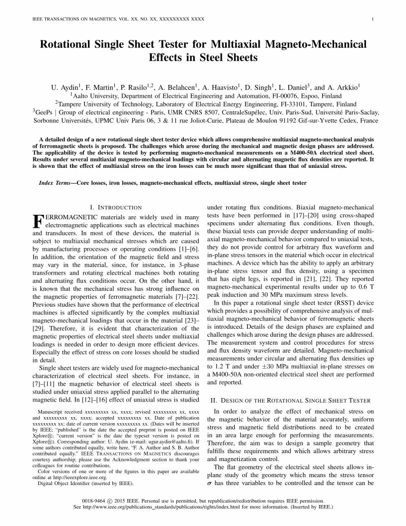
In Fig. 13 the percentage variations of the coercive fieldcompared to stress free case are shown. These variations arecalculated for each measurement similar to (12) as
∆Hc =Hc(σxx, σyy, σxy)−Hc(0, 0, 0)
Hc(0, 0, 0). (13)
An analogy between loss and coercive field variations isobserved. Similar results were reported for instance in [12],[16], [18], [19].
IEEE TRANSACTIONS ON MAGNETICS, VOL. XX, NO. XX, XXXXXXXXX XXXX 9
Fig. 13. Measured alternating coercive field variations with respect to stressfree case (Hc) for each stress state with 1.2 T induction level (a) at rolling(x) direction, (b) at transverse (y) direction.
C. Repeatability of the Measurements
In order to test the repeatability of the measurements, fewmeasurements under zero stress and various uniaxial andbiaxial stress configurations were repeated after dismantlingand assembling the sample again. Studied stress configurationsare shown in Fig. 7 with dot markers. Both rotating andalternating field cases were studied. The studied peak inductionlevels were 1 T and 1.2 T for rotational and alternating fields,respectively. Considering the stress free case the maximumdifferences between the newer and the older measurementsfor the loss and field strength were 7.44% and 8.44% un-der rotating and 3.70% and 5.83% under alternating field,respectively. As stated in [40], usually the accuracy of arotational single sheet tester without stress application is notbetter than 7%. Indeed including the stressing mechanism tothe system increased the maximum differences for the loss andfield strength to 11.75% and 14.4% under rotating and 4.19%and 8.39% under alternating field, respectively. Some of thesources that can affect the repeatability are alignment of theforce actuators with respect to the sample, orientation of therolling and transverse directions of the specimen with respectto the force actuators, ambient temperature, friction betweenthe sample, sample holder and reinforcing plates, wear andtear of the components. Detailed repeatability and uncertaintyanalysis of the presented measurement system are complexand lengthy tasks and will be a part of a future work.
V. CONCLUSION
A new rotational single sheet tester device dedicated to testthe multiaxial magneto-mechanical behavior of ferromagneticsheets is introduced by explaining the design phases of thedevice. The applicability of the device is tested on a M400-50A grade electrical steel sheet. Results under controlled cir-cular and alternating flux density and under several multiaxialstress states are reported. The results show that the effect ofmultiaxial stress on the rotational and alternating core lossescan be much more significant than that of uniaxial stress.Therefore, it is clear that in order to design higher efficiencymachines, the effect of multiaxial stress on the material should
be considered. In order to do that, accurate models can becreated by analysing the measurement results in detail. Infuture work, measurements under several excitation frequen-cies and higher stress magnitudes will be made. In addition,magnetostriction under multiaxial stress will be measured.
ACKNOWLEDGMENT
The research leading to these results has received fundingfrom the European Research Council under the EuropeanUnions Seventh Framework Programme (FP7/2007-2013)/ERC grant agreement no 339380. P. Rasilo and F. Martinacknowledge the Academy of Finland for financial supportunder grants 274593, 304112 and 297345.
REFERENCES
[1] Y. Kai, Y. Tsuchida, T. Todaka, and M. Enokizono, “Evaluation of localresidual stress distribution of stator core in rotating machine,” EEJ Trans.Fun. Mat., vol. 131, no. 5, pp. 389–394, May 2011.
[2] P. Baudouin, A. Belhadj, F. Breaban, A. Deffontaine, , and Y. Houbaert,“Effects of laser and mechanical cutting modes on the magnetic proper-ties of low and medium si content nonoriented electrical steels,” IEEETrans. Magn., vol. 38, no. 5, pp. 3213–3215, Sep. 2002.
[3] D. J. B. Smith, B. C. Mecrow, G. J. Atkinson, A. G. Jack, and A. A. A.Mehna, “Shear stress concentrations in permanent magnet rotor sleeves,”in Proc. Int. Conf. Electr. Mach., ICEM, Rome, Italy, Sep. 2010, pp. 1–6.
[4] F. Chai, Y. Li, P. Liang, and Y. Pei, “Calculation of the maximummechanical stress on the rotor of interior permanent magnet synchronousmotors,” IEEE Trans. Ind. Electron., vol. 63, no. 6, pp. 3420–3432, Feb.2016.
[5] A. Borisavljevic, H. Polinder, and J. A. Ferreira, “On the speed limitsof permanent-magnet machines,” IEEE Trans. Ind. Electron., vol. 57,no. 6, pp. 220–227, Jan. 2010.
[6] D. Gerada, A. Mebarki, N. Brown, and C. G. K.J. Bradley, “Designaspects of high-speed high-power-density laminated-rotor induction ma-chines,” IEEE Trans. Ind. Electron., vol. 58, no. 9, pp. 4039–4047, Sep.2011.
[7] N. Leuning, S. Steentjes, M. Schulte, W. Bleck, and K. Hameyer,“Effect of elastic and plastic tensile mechanical loading on the magneticproperties of ngo electrical steel,” J. Magn. Magn. Mater., vol. 417, pp.42–48, Nov. 2016.
[8] O. Perevertov, J. Thielsch, and R. Schfer, “Effect of applied tensile stresson the hysteresis curve and magnetic domain structure of grain-orientedtransverse fe-3%si steel,” J. Magn. Magn. Mater., vol. 385, pp. 358–367,Jul. 2015.
[9] O. Perevertov, “Influence of the applied elastic tensile and compressivestress on the hysteresis curves of fe-3%si non-oriented steel,” J. Magn.Magn. Mater., vol. 428, pp. 223–228, Apr. 2017.
[10] M. LoBue, C. Sasso, V. Basso, F. Fiorillo, and G. Bertotti, “Power lossesand magnetization process in fesi non-oriented steels under tensile andcompressive stress,” J. Magn. Magn. Mater., vol. 215-216, pp. 124–126,Jun. 2000.
[11] Y. Kai, Y. Tsuchida, T. Todaka, and M. Enokizono, “Influence of stresson vector magnetic property under alternating magnetic flux conditions,”IEEE Trans. Magn., vol. 47, no. 10, pp. 4344–4347, Oct. 2011.
[12] V. Permiakov, A. Pulnikov, L. Dupre, and J. Melkebek, “Rotationalmagnetization in nonoriented fe-si steel under uniaxial compressive andtensile stress,” IEEE Trans. Magn., vol. 40, pp. 2760–2762, Jul. 2004.
[13] C. Krell, N. Baumgartinger, G. Krismanic, E. Leiss, and H. Pftzner,“Stress effects on the multidirectional magnetic behaviour of grain-oriented silicon iron sheets,” J. Magn. Magn. Mater., vol. 215-216, pp.63–65, Jun. 2000.
[14] Y. Kai, Y. Tsuchida, T. Todaka, and M. Enokizono, “Developement ofsystem for vector magnetic property measurement under stress,” Jour.Elec. Eng., vol. 61, no. 7/s, pp. 77–80, 2011.
[15] Y. Kai, Y. Tsuchida, T. Todaka, and M. Enokizono, “Measurementof vector magnetic property under stress along arbitrary direction innon-oriented electrical steel sheet,” Przeglad Elektrotechniczny, vol. 87,no. 9b, pp. 101–105, 2011.
[16] Y. Kai, Y. Tsuchida, T. Todaka, and M. Enokizono, “Influence of stresson vector magnetic property under rotating magnetic flux conditions,”IEEE Trans. Magn., vol. 48, no. 4, pp. 1421–1424, Apr. 2012.

IEEE TRANSACTIONS ON MAGNETICS, VOL. XX, NO. XX, XXXXXXXXX XXXX 10
[17] M. Rekik, O. Hubert, and L. Daniel, “Influence of a multiaxial stresson the reversible and irreversible magnetic behaviour of 3% si-fe alloy,”Int. J. Appl. Electromagn. Mech., vol. 44, no. 3-4, pp. 301–315, Mar.2014.
[18] Y. Kai, Y. Tsuchida, T. Todaka, and M. Enokizono, “Influence ofbiaxial stress on vector magnetic properties and 2-d magnetostrictionof a nonoriented electrical steel sheet under alternating magnetic fluxconditions,” IEEE Trans. Magn., vol. 50, no. 4, p. 6100204, Apr. 2014.
[19] J. Pearson, P. T. Squire, M. G. Maylin, and J. G. Gore, “Apparatusfor magnetic measurements under biaxial stress,” IEEE Trans. Magn.,vol. 36, no. 5, pp. 3599–3601, 2000.
[20] O. Hubert, F. S. Mballa-Mballa, S. He, and S. Depeyre, “Influence ofbiaxial stress on magnetic behavior of dual-phase steel – experimentsand modeling,” IEEE Trans. Magn., vol. 52, no. 5, p. 6201004, May2016.
[21] Y. Kai, M. Enokizono, and Y. Kido, “Influence of shear stress on vectormagnetic properties on non-oriented electrical steel sheets,” Int. J. Appl.Electromagn. Mech., vol. 44, no. 3-4, pp. 371–378, Mar. 2014.
[22] Y. Kai and M. Enokizono, “Effect of arbitrary shear stress on vectormagnetic properties of non-oriented electrical steel sheets,” IEEE Trans.Magn., vol. 53, p. 17282713, May 2017.
[23] A. Basak, A. J. Moses, and R. Al-Bir, “Effect of clamping stress onpower loss in powercore strip and si-fe transformer cores,” IEEE Trans.Magn., vol. 26, no. 5, pp. 1999–2001, Sep. 1990.
[24] A. J. Moses and H. Rahmatizadeh, “Effects of stress on iron loss andflux distribution of an induction motor stator core,” IEEE Trans. Magn.,vol. 25, no. 5, pp. 4003–4005, Sep. 1989.
[25] S. Zeze, Y. Kai, T. Todaka, and M. Enokizono, “Vector magnetic char-acteristic analysis of a pm motor considering residual stress distributionwith complex-approximated material modelling,” IEEE Trans. Magn.,vol. 48, no. 11, pp. 3352–3355, Nov. 2012.
[26] K. Yamazaki and Y. Kato, “Iron loss analysis of interior permanentmagnet synchronous motors by considering mechanical stress and de-formation of stators and rotors,” IEEE Trans. Magn., vol. 50, no. 2, p.7022504, Feb. 2014.
[27] D. Miyagi, N. Maeda, Y. Ozeki, K. Miki, and N. Takashi, “Estimationof iron loss in motor core with shrink fitting using fem analysis,” IEEETrans. Magn., vol. 45, no. 3, pp. 1704–1707, Mar. 2009.
[28] K. Delaere, W. Heylen, R. Belmans, and K. Hameyer, “Comparison ofinduction machines stator vibration spectra induced by reluctance forcesand magnetostriction,” IEEE Trans. Magn., vol. 38, no. 2, pp. 969–972,Mar. 2002.
[39] O. Hubert, L. Daniel, and R. Billardon, “Experimental analysis of themagnetoelastic anisotropy of a non-oriented silicon iron alloy,” J. Magn.Magn. Mater., vol. 254-255, pp. 352–354, Jan. 2003.
[29] L. Bernard and L. Daniel, “Effect of stress on magnetic hysteresis lossesin a switched reluctance motor: application to stator and rotor shrinkfitting,” IEEE Trans. Magn., vol. 51, p. 7002513, May 2015.
[30] U. Aydin, P. Rasilo, D. Singh, A. Lehikoinen, A. Belahcen, andA. Arkkio, “Coupled magneto-mechanical analysis of iron sheets underbiaxial stress,” IEEE Trans. Magn., vol. 52, no. 3, p. 2000804, Mar.2016.
[31] J. Sievert, “Two-dimensional magnetic measurements-history andachievements of the workshop,” Przeglad Elektrotechniczny, vol. 87,no. 9b, pp. 2–10, 2011.
[32] Y. Guo, J. G. Zhu, J. Zhong, H. Lu, and J. X. Jin, “Measurement andmodeling of rotational core losses of soft magnetic materials used inelectrical machines: a review,” IEEE Trans. Magn., vol. 44, no. 2, pp.279–291, Feb. 2008.
[33] D. Singh, F. Martin, P. Rasilo, and A. Belahcen, “Magnetomechanicalmodel for hysteresis in electrical steel sheet,” IEEE Trans. Magn.,vol. 52, p. 7301109, Jul. 2016.
[34] J. J. Zhong, Y. G. Guo, and Z. W. L. J. G. Zhu, “Characteristics of softmagnetic composite material under rotating magnetic fluxes,” J. Magn.Magn. Mater., vol. 299, pp. 29–34, Apr. 2006.
[35] S. Zurek and T. Meydan, “Errors in the power loss measured in clock-wise and anticlockwise rotational magnetisation. part 1: Mathematicalstudy,” J. Magn. Magn. Mater., vol. 153, pp. 147–151, Jul. 2006.
[36] K. Matsubara, N. Takahashi, K. Fujiwara, M. N. T. Nakata, and H. Aoki,“Acceleration technique of waveform control for single sheet tester,”IEEE Trans. Magn., vol. 31, no. 6, pp. 3400–3402, Nov. 1995.
[37] A. Visioli, “Tuning of pid controllers with fuzzy logic,” IEE Proc. Cont.Theo. Appl., vol. 148, pp. 1–8, Jan. 2001.
[38] Z. Jinhua, Z. Jian, D. Haifeng, and W. Sun’an, “Self-organizing geneticalgorithm based tuning of pid controllers,” Inf. Sci., vol. 179, pp. 1007–1018, Mar. 2009.
[40] S. Zurek, “Two-dimensional magnetisation problems in electrical steels,”Ph.D. dissertation, Cardiff University, Whales/United Kingdom, Mar.2005.
[41] W. Salz and K. A. Hempel, “Which field sensors are suitable for arotating flux apparatus?” in Proc. 1st Int. Work. on Magn. Prop. Elec.Sheet Steel Under Two-dim. Excit., Braunschweig, Germany, Apr. 1992,pp. 117–126.
[42] K. Mori, S. Yanase, Y. Okazaki, and S. Hashi, “2-d magnetic rotationalloss of electrical steel at high magnetic flux density,” IEEE Trans. Magn.,vol. 41, no. 10, pp. 3310–3312, Oct. 2004.


![Journal of Magnetism and Magnetic Materials - …butler.cc.tut.fi/~rasilo/pubs/Aydin2018.pdf · the losses, they used magneto-mechanical measurements from [22] with non-sinuoidal](https://img.dokumen.tips/doc/110x75/5b8467c07f8b9ad34a8c281b/journal-of-magnetism-and-magnetic-materials-rasilopubsaydin2018pdf-the.jpg)