Embed Size (px)
Citation preview

ROSA® Knee System
Surgical Technique V 1.1

Table of Contents
System Overview .................................................................................................................. 2 System Description ......................................................................................................... 2 Indications for Use ........................................................................................................... 5 Contraindications ............................................................................................................ 5 Training ........................................................................................................................... 5
Preoperative Guide ............................................................................................................... 6 OR Setup ......................................................................................................................... 6
Instrumentation Assembly ................................................................................................... 7 ROSA Arm Instrument Interface on the Robotic Arm ....................................................... 7 ROSA Arm Reference Frame on the Robotic Arm ............................................................. 8 ROSA Base Reference Frame on the Robotic Unit ............................................................ 8 ROSA TKA Cut Guide on the Robotic Arm ........................................................................ 9 Universal Validation Tool Body and Distal & Posterior Condyles Digitizer Validation ........ 9 Disposables ....................................................................................................................10
Installation ............................................................................................................................11 Device Start Up ..............................................................................................................11 Starting a Case ...............................................................................................................12 Welcome Screen ............................................................................................................12
SURGEON Panel ....................................................................................................................13 SURGEON Panel Overview .............................................................................................13
SETUP Panel ..........................................................................................................................15 Calibration of Sensor ......................................................................................................15 Draping ..........................................................................................................................16 Touchscreen Monitor Draping ........................................................................................17 ROSA Positioning ...........................................................................................................18 Camera Positioning ........................................................................................................19 ROSA Registration ......................................................................................................... 20
Intraoperative Guide .....................................................................................................21 Trackers Installation .......................................................................................................21 Install Trackers .............................................................................................................. 22
FEMUR and TIBIA Panel ....................................................................................................... 24 Femoral Landmarking ................................................................................................... 24 Tibial Landmarking ........................................................................................................ 28
Knee Evaluation ....................................................................................................................31 EVALUATION Panel Overview .........................................................................................31
PLANNING Panel ................................................................................................................. 34 Planning Panel Overview ............................................................................................... 34 Implant Selection .......................................................................................................... 34 Implant Manipulator ...................................................................................................... 35 Frontal View .................................................................................................................. 35 Lateral View ................................................................................................................... 36 Tibial Axial View............................................................................................................. 36 Viewing Options .............................................................................................................37 Balance Tool ................................................................................................................. 38 Femoral and Tibial Components Planning ..................................................................... 39

RESECTIONS Drawer ........................................................................................................... 40 RESECTIONS Drawer Overview ..................................................................................... 40 ROSA TKA Cut Guide Installation and Checkpoint ..........................................................41 Femoral Distal Resection ............................................................................................... 42 Tibial Proximal Resection ............................................................................................... 45 Femoral Rotation (Optional) ...........................................................................................47 Femoral 4-in-1 Resection ............................................................................................... 50 Implant Confirmation Window ...................................................................................... 53 Final Knee Evaluation (Optional) .................................................................................... 53
Postoperative Guide ............................................................................................................ 54 Shutdown ...................................................................................................................... 54 Device Storage .............................................................................................................. 54
Instrumentation .................................................................................................................. 55 ROSA Knee Instruments ................................................................................................ 55 ROSA Knee Disposables ................................................................................................ 56
2 | ROSA Knee System Surgical Technique
Touchscreen
Robotic arm
Sliding shelfRobotic unit base
Wheels with cable
pushers and brakes
Storage areas
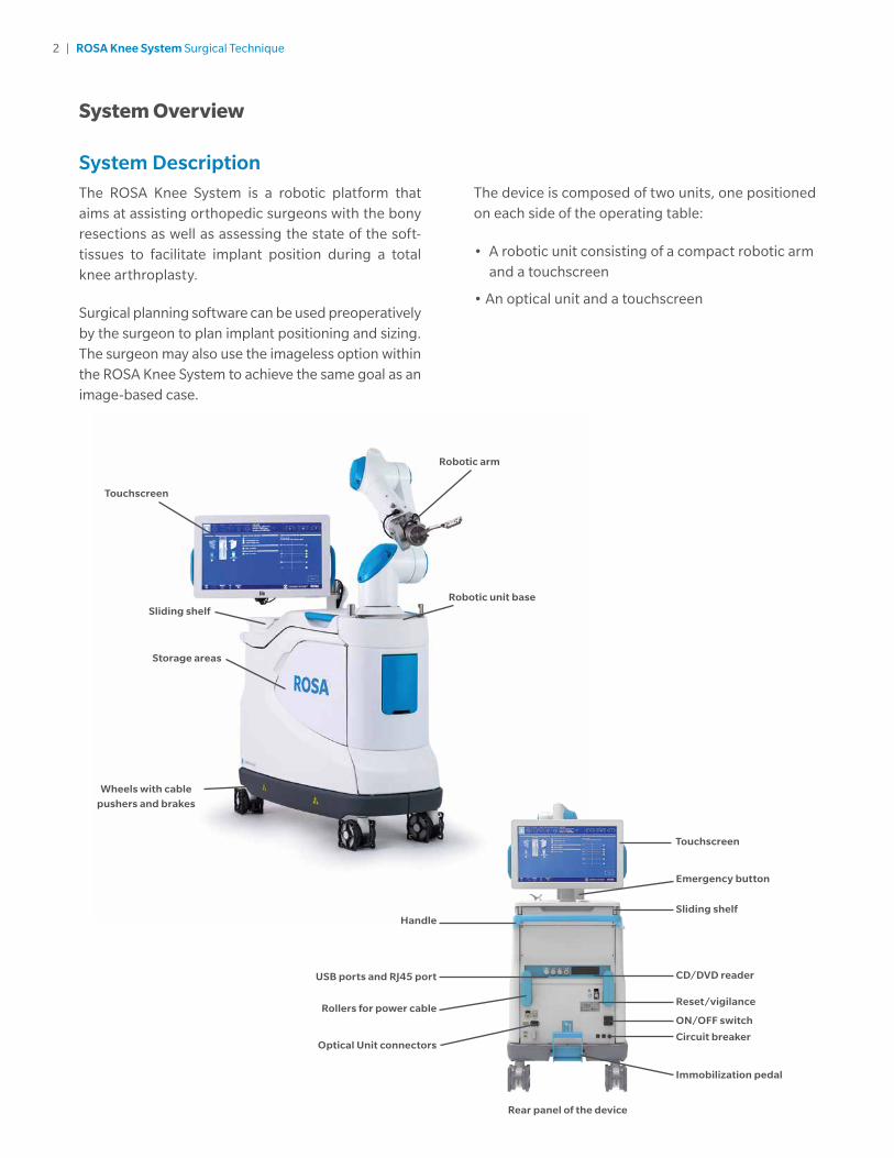
System DescriptionThe ROSA Knee System is a robotic platform that aims at assisting orthopedic surgeons with the bony resections as well as assessing the state of the soft-tissues to facilitate implant position during a total knee arthroplasty.
Surgical planning software can be used preoperatively by the surgeon to plan implant positioning and sizing. The surgeon may also use the imageless option within the ROSA Knee System to achieve the same goal as an image-based case.
System Overview
The device is composed of two units, one positioned on each side of the operating table:
• A robotic unit consisting of a compact robotic arm and a touchscreen
• An optical unit and a touchscreen
Touchscreen
HandleSliding shelf
Emergency button
CD/DVD reader
Reset/vigilance
ON/OFF switch
Circuit breaker
Immobilization pedal
USB ports and RJ45 port
Rollers for power cable
Optical Unit connectors
Rear panel of the device

3 | ROSA Knee System Surgical Technique
System Description (cont.) Robotic Arm
The robotic arm is equipped with a force sensor that allows users to manually move the robotic unit to the desired location by measurement of forces exerted at the end of the arm and a compensation principle, regardless of the instrument used (Figure 1).
Touchscreen
The device includes two touchscreens displaying the user interface, one on the robotic unit and one on the optical unit (Figure 2).
Immobilization System
The robotic unit is equipped with a system immobilizing it to the ground. This system is composed of four stabilization feet, activated by a pedal. Two positions are available: the unit is immobilized when the pedal is down, the unit is mobile when the pedal is up. Additionally, each wheel of the robotic unit can be locked individually (Figure 3).
Note: Do not place fingers or feet under the stabilization feet before immobilization of the system.
Note: Verify the position of the device and its environment when using the robotic unit immobilization system. Confirm cables or wires are cleared from the area of the stabilization feet to prevent damage.
Figure 2
Figure 1
Figure 3
Pedal in up postion Mobile
Pedal in down postion Immobilized

4 | ROSA Knee System Surgical Technique
Figure 4 Figure 5
Vigilance Device (Foot Pedal)
Optical Unit
The optical unit is composed of (Figure 5):
• The optical camera
• The camera positioning arm
• The touchscreen
Note: The device uses a laser integrated into the optical camera. This laser is of class 2 (power inferior to 1 mW, eye protection by the palpebral reflex). Do not orient the laser beam to the eyes or to any light reflecting surfaces such as mirrors to avoid any direct or indirect exposure to laser beam.
Note: Do not orient the laser towards the patient’s eyes, the user’s eyes or anyone else’s eyes.
System Description (cont.) Vigilance Device (Foot Pedal)
The device is equipped with a foot pedal for activating the robotic arm movements. The robotic arm will only move if the user presses the foot pedal. This operating principle applies to the SETUP and RESECTIONS panels. The robotic arm movement ceases as soon as the user releases the foot pedal (Figure 4).
Note: Ensure that the foot pedal is operating correctly before beginning a procedure. Visually inspect the device and perform a test for interruption/resumption of a robotic arm movement.
Touchscreen
Optical camera
Wheels with cable pushers and brakes
Positioning arm
Handle

5 | ROSA Knee System Surgical Technique
ContraindicationsThe ROSA Knee System may not be suitable for use in cases of:
• Hip pathology with significant bone loss (e.g. avascular necrosis of the femoral head with collapse, severe dysplasia of the femoral head or the acetabulum)
• Hip pathology severely limiting range of motion (e.g. arthrodesis, severe contractures, chronic severe dislocation)
• Active infections of the knee joint area
• Knee replacement revision surgery
• Presence of strong infrared sources or infrared reflectors in the vicinity of the NavitrackER® devices
• Implants that are not compatible with the system
• Contraindications for the implant as given by the implant manufacturer
TrainingThis device is a surgery assistance tool. It should only be used by authorized surgeons trained in the use of the device by Zimmer Biomet or by personnel authorized by Zimmer Biomet. It is not a replacement
for the surgeon’s expertise and experience.
Indications for UseThe ROSA Knee System is indicated as a stereotaxic instrumentation system for total knee athroplasty (TKA). It is to assist the surgeon in providing software-defined spatial boundaries for orientation and reference information to identifiable, anatomical structures for the accurate placement of knee implant components.
The robotic arm placement is performed relative to anatomical landmarks as recorded using the system intraoperatively, and based on a surgical plan, optionally determined preoperatively using compatible X-ray or MRI based surgical planning tools.
It includes a robotic arm, an optical tracking system and accessories, software system, surgical instruments and accessories.
The targeted population has the same characteristics as the population that is suitable for the implants compatible with the ROSA Knee System.
The ROSA Knee System is to be used with the following fixed bearing knee replacement systems in accordance with their indications and contraindications: NexGen® CR, NexGen CR-Flex, NexGen CR-Flex Gender, NexGen LPS, NexGen LPS-Flex, NexGen LPS-Flex Gender, Persona® CR, Persona PS, Vanguard® CR, and Vanguard PS.
Positioning arm
Handle
For complete instructions for use, including troubleshooting and warnings, refer to the ROSA Knee User Manual and Surgical Technique.

6 | ROSA Knee System Surgical Technique
OR SetupThe patient is placed on the surgical table in supine position. The robotic unit is positioned approximately at the patient’s hip, and approximately 45° relative to the surgery table. Two patient bone references are installed on the patient’s femur and tibia as a reference for leg movements. A third reference is located on the robotic unit (on the post of the ROSA Base Reference Bar closest to the surgical table), to track where the robotic unit is relative to the patient’s leg during the surgery.
Note: During the surgery, the surgeon must always stay on the same side as the robotic unit.
Preoperative Guide
Figure 7
Maximum height of patient to minimize tracker visibility problems.
114.3cm
45in 35in
10in25.4cm
88.9cm
Figure 6
Possible OR setups
13 ROSA® Knee System-Surgical Technique Rev2 (180420)
Possible OR setups
Maximum height of patient to minimize tracker visibility problems.
1.1 Device start up
Right Knee Left Knee
Surg
eon
sam
e sid
e as
ope
rate
d kn
ee
Surg
eon
oppo
site
side
of o
pera
ted
knee
13 ROSA® Knee System-Surgical Technique Rev2 (180420)
Possible OR setups
Maximum height of patient to minimize tracker visibility problems.
1.1 Device start up
Right Knee Left Knee
Surg
eon
sam
e sid
e as
ope
rate
d kn
ee
Surg
eon
oppo
site
side
of o
pera
ted
knee
Right Knee Left Knee
Su
rgeo
n o
pp
osi
te s
ide
of o
per
ated
kn
eeS
urg
eon
sam
e si
de
as o
per
ated
kn
ee
Note: The maximum height of the patient on the OR table should be 45 inches to minimize tracker visibility problems. In case of a patient with a high BMI, lower the table to avoid visibility problems (Figure 6).
There are four possible OR setups (Figure 7):
• Operating a right knee, with the surgeon on the same side as the operated knee
• Operating a right knee, with the surgeon on the opposite side of the operated knee
• Operating a left knee, with the surgeon on the same side as the operated knee
• Operating a left knee, with the surgeon on the opposite side of the operated knee

7 | ROSA Knee System Surgical Technique
ROSA Arm Instrument Interface on the Robotic Arm• Align the groove on the back of the ROSA Arm
Instrument Interface (laser marked arrow on the side) with the peg of the electric insulator of the robotic arm (Figure 8).
• Assemble instruments together until the base of the ROSA Arm Instrument Interface is completely seated.
• Secure the ROSA Arm Instrument Interface by firmly tightening the three captive screws using a hexagonal screwdriver (Figure 9).
Instrumentation Assembly
Note: Always verify the proper installation of an instrument to the robotic unit or robotic arm by confirming screws are firmly tightened.
Note: To avoid touching the non-sterile part of the robotic unit and to preserve sterility, always use the handles to hold the ROSA Arm Instrument Interface in place during installation.
Note: Do not apply excessive torque on screws when installing an instrument. Do not use power tools.
Figure 8 Figure 9

8 | ROSA Knee System Surgical Technique
ROSA Arm Reference Frame on the Robotic Arm• Align the groove of the ROSA Arm Reference Frame
with the peg of the ROSA Arm Instrument Interface (Figures 10 and 11).
• Assemble instruments together until the base of the ROSA Arm Reference Frame is completely seated.
• Secure ROSA TKA Cut Guide by firmly tightening by the two captive screws by hand (Figure 12).
ROSA Base Reference Frame on the Robotic Unit• Open the clamp of the ROSA Base Reference Frame
and align it on the post closest to the surgical table (Figure 13).
• Assemble instruments together until the ROSA Base Reference Frame is completely seated vertically.
• Close the clamp and bring the hand screw over the clamp.
• Secure the ROSA Base Reference Frame by firmly tightening the screw by hand (Figure 14).
Figure 10 Figure 11 Figure 12
Figure 13 Figure 14

9 | ROSA Knee System Surgical Technique
ROSA TKA Cut Guide on the Robotic Arm• Align the groove of the ROSA TKA Cut Guide with
the peg of the ROSA Arm Instrument Interface (Figure 15).
• Assemble instruments together until the base of the ROSA TKA Cut Guide is completely seated.
• Secure ROSA TKA Cut Guide by firmly tightening the two captive screws by hand (Figure 16).
Universal Validation Tool Body and Distal & Posterior Condyles Digitizer ValidationTibial Proximal Resection
• These two instruments need to be assembled together for the validation of the tibial proximal resection.
• Verify the two instruments are locked together using the lever (Figure 17).
Note: For the validation of the tibial proximal resection, confirm the Universal Validation Tool Body and Distal & Posterior Condyle Digitizer are locked together using the lever.
Femoral Distal Resection
• Only the Universal Validation Tool Body is used for the validation of the femoral distal resection.
• Ensure to disconnect the Distal & Posterior Condyles Digitizer from the Universal Validation Tool Body (Figure 18).
Figure 18Figure 17
Figure 15 Figure 16

10 | ROSA Knee System Surgical Technique
DisposablesReflective Trackers (NavitrackER Device) Installation
The NavitrackER devices must be installed on each instrument used for optical tracking. To facilitate the installation of the trackers on the instruments, push the marker on each mounting stud using the NavitrackER pliers until fully seated. A click should be heard. It is important to verify that the NavitrackER devices remain clean throughout the surgery.
The Universal Validation Tool Body is laser marked either RIGHT or LEFT. Depending on the OR setup, utilize the table above to install the NavitrackER devices on the correct side (Table 1).
Note: Always use NavitrackER pliers for the installation. Ensure that reflective NavitrackER devices are fully seated.
Note: Verify the proper fixation of the NavitrackER devices on each instrument (ROSA Base & Arm Reference Frame, ROSA Registration Pointer, Tibial & Femoral Reference Frame, and Universal Validation Tool Body). Always use the NavitrackER pliers for installation.
Note: Always minimize handling of the NavitrackER devices, since errors may result from the non-uniform reflection of their surface.
Note: Always use unblemished trackers.
Note: Each NavitrackER device is single use and should not be re-sterilized to be reused in surgery.
The NavitrackER devices must be installed on all used instruments for optical tracking using the NavitrackER pliers. Push the marker onto the mounting studs until it is fully seated. It is important to verify that the NavitrackER devices remain clean throughout the surgery.
Table 1
Right knee operated Left knee operated
Surgeon same side as operated knee Tracker on RIGHT side Tracker on LEFT side
Surgeon opposite side as operated knee Tracker on LEFT side Tracker on RIGHT side

11 | ROSA Knee System Surgical Technique
Installation
Figure 19
Note: In order to prevent accidental detachment of connectors, ensure the metallic ring attaches to the robotic unit’s hook. Lock the connector in place using the metallic clip.
Note: Confirm the metallic ring of the optical unit cable is attached to the hook on the rear panel of the robotic unit to ensure EMC protection.
If the screen remains black at start up:
• Check that the touchscreen is powered (button on the right side of the screen) and/or
• Restart the computer by pushing the button located on the rear panel of the device.
Note: To restart the device, wait at least 10 seconds after shutting down, and the extinction of the restart button light.
Device Start Up Switching the Device ON
• Place the robotic unit on one side of the operating table and the optical unit on the opposite side. Plug the optical unit to the robotic unit. Be sure to plug the white and black cables into the corresponding white and black ports.
• Plug the power supply cable into a power source of the appropriate voltage.
• Attach the metallic ring of the optical unit cable to the hook on the robotic unit rear panel. Lock the connector in place using the metallic clip.
• Switch the robot ON.
• Allow the camera to warm up for few minutes (Figure 19).
ON/OFF switch
Hook

12 | ROSA Knee System Surgical Technique
Figure 23Figure 22
Figure 21Figure 20
Welcome ScreenUpon launching a case, a welcome screen will appear where the user can confirm the patient ID, procedure laterality, implant family and instrumentation. Once the user has confirmed the information is correct, the ROSA Knee Software can be launched. If the information is incorrect, the user can quit and relaunch the correct case (Figure 23).
Starting a Case• The case management application will start upon
powering up the system.
• Insert a USB key containing the encrypted case(s) in a USB port (Figure 20).
• Use the SYNC function to upload the case(s) to the ROSA Clinical Computer (Figure 21).
• Use the CASES function to search for the case to be launched (at least three letters) (Figure 22).
• Select the appropriate case and click Launch.
• Type in the PIN for the selected case.
USB ports

13 | ROSA Knee System Surgical Technique
Figure 24
By default, the posterior condylar axis (PCA) cannot be unselected and will always be displayed.
Knee State Evaluation
The Knee State Evaluation provides quantitative information about the operative leg’s range of motion (in degrees) with alignment of the leg, as well as varus/valgus deformity (in degrees) at different angles and ligament laxity (mm; in flexion and extension) when the surgeon proceeds with a stress test of the operative leg.
If the Knee State Evaluation is selected by clicking “Apply to workflow”, the EVALUATION button will appear in the panel buttons and will allow the surgeon to perform the stress test at different stages of the procedure (Initial, Intra-Op and Final). Conversely, if not selected, the EVALUATION button will not appear in the panel buttons and no values will be recorded by the ROSA Knee System.
SURGEON Panel Overview
In the SURGEON panel of ROSA Knee Software, the user can select their preferences for certain intraoperative parameters. Preferences are classified into the following categories:
• Femoral Rotation Axis Display
• Knee State Evaluation
• Femoral Rotation Tool
• Flexion Angles for Stress Tests
A green checkmark indicates the option is selected. Depending on the preferences, the panel buttons will show different surgical steps to perform during the procedure (e.g. EVALUATION panel and FEMORAL ROTATION TOOL in the RESECTIONS drawer) (Figure 24).
• Click DONE after all preferences are chosen to proceed to the SETUP panel.
Femoral Rotation Axis Display
The ROSA Knee System can display different femoral rotation axes in the PLANNING panel, based on surgeon preferences:
• Posterior Condylar Axis (PCA)
• Transepicondylar Axis (TEA)
• Anterior Posterior Axis (AP)
SURGEON Panel

14 | ROSA Knee System Surgical Technique
Flexion Angles for Stress Tests
This option enables the selection of the 30, 45, 60 and 120 degrees of flexion indicators in the EVALUATION panel in addition to the 0 and 90 degrees required values. By default, the 0 and 90 degrees cannot be unselected and will always be displayed.
SURGEON Panel Overview (cont.)
Femoral Rotation Tool
The Femoral Rotation Tool provides quantitative information about ligament laxity (mm; flexion and extension) when the surgeon proceeds with a pull test (manually or with instruments such as a laminar spreader or Zimmer FuZion®). Femoral rotation values will be displayed and can be captured to be applied to the surgical plan.
If the Femoral Rotation Tool is selected by clicking “Apply to workflow”, a FEMORAL ROTATION button will appear in the RESECTIONS drawer and will allow the surgeon to evaluate the gaps in extension and the femoral rotation of the implant following a pull test. Conversely, if not selected, the FEMORAL ROTATION button will not appear on the surgery workflow and no values will be recorded by the ROSA Knee System.
Figure 25

15 | ROSA Knee System Surgical Technique
Figure 27
Figure 26
Figure 28
Calibrate the Force Sensor
• Acknowledge the ROSA Arm is free of any force (checkmarks) and click YES (Figure 28).
• If unsuccessful, redo calibration.
• If successful, click NEXT to proceed to draping.
Note: Do not touch the robotic arm. Only the ROSA Arm Instrument Interface should be installed on the robotic arm.
Calibration of Sensor
Move the Robotic Arm to Drape Position
• In the SETUP panel, press the foot pedal to move the robotic arm to the draping position (Figure 26).
Install the ROSA Arm Instrument Interface
• Once the robotic arm is in the draping position, install the ROSA Arm Instrument Interface by firmly tightening the three captive screws using the hexagonal screwdriver (Figure 27).
• Click NEXT to move to calibration of the force sensor.
Note: Do not apply excessive torque on screws when installing an instrument. Do not use power tools.
SETUP Panel
16 | ROSA Knee System Surgical Technique
Figure 29 Figure 30
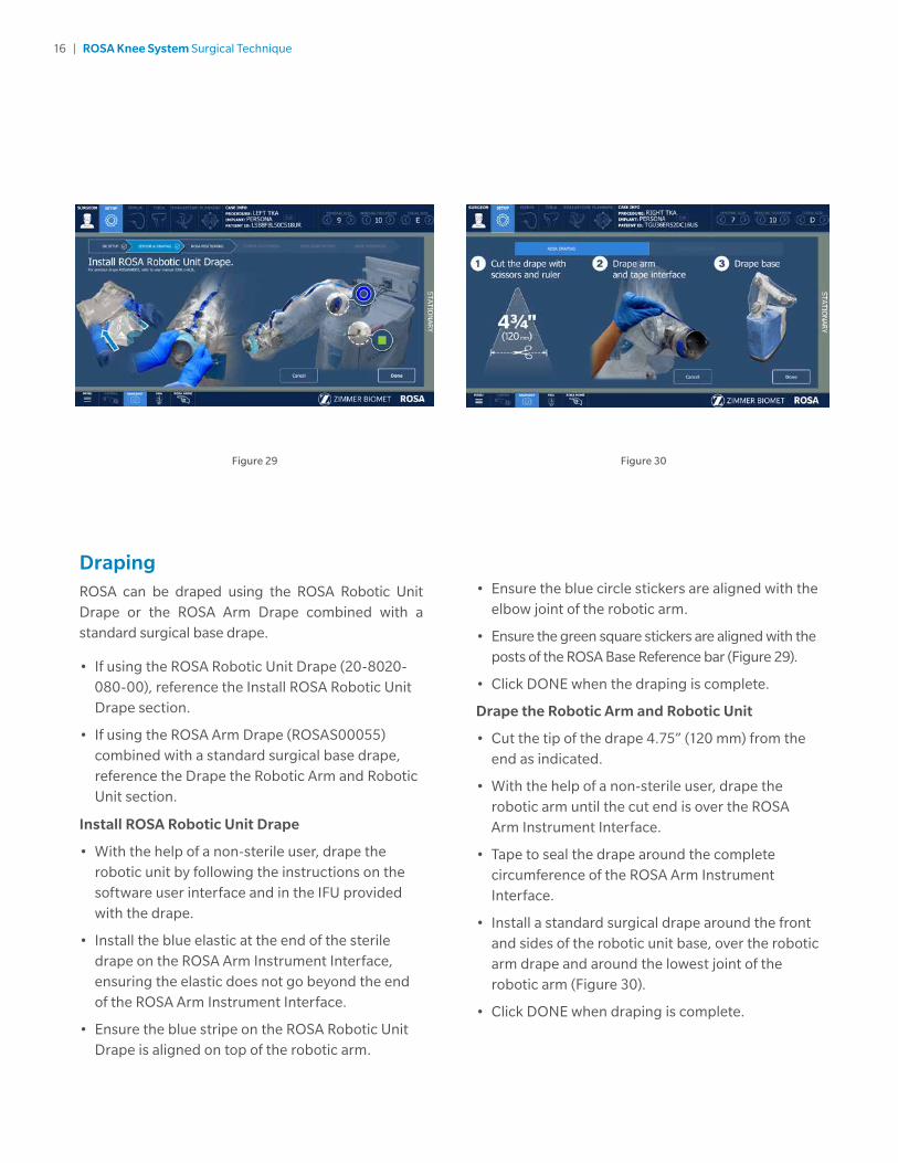
• Ensure the blue circle stickers are aligned with the elbow joint of the robotic arm.
• Ensure the green square stickers are aligned with the posts of the ROSA Base Reference bar (Figure 29).
• Click DONE when the draping is complete.
Drape the Robotic Arm and Robotic Unit
• Cut the tip of the drape 4.75” (120 mm) from the end as indicated.
• With the help of a non-sterile user, drape the robotic arm until the cut end is over the ROSA Arm Instrument Interface.
• Tape to seal the drape around the complete circumference of the ROSA Arm Instrument Interface.
• Install a standard surgical drape around the front and sides of the robotic unit base, over the robotic arm drape and around the lowest joint of the robotic arm (Figure 30).
• Click DONE when draping is complete.
Draping ROSA can be draped using the ROSA Robotic Unit Drape or the ROSA Arm Drape combined with a standard surgical base drape.
• If using the ROSA Robotic Unit Drape (20-8020-080-00), reference the Install ROSA Robotic Unit Drape section.
• If using the ROSA Arm Drape (ROSAS00055) combined with a standard surgical base drape, reference the Drape the Robotic Arm and Robotic Unit section.
Install ROSA Robotic Unit Drape
• With the help of a non-sterile user, drape the robotic unit by following the instructions on the software user interface and in the IFU provided with the drape.
• Install the blue elastic at the end of the sterile drape on the ROSA Arm Instrument Interface, ensuring the elastic does not go beyond the end of the ROSA Arm Instrument Interface.
• Ensure the blue stripe on the ROSA Robotic Unit Drape is aligned on top of the robotic arm.

17 | ROSA Knee System Surgical Technique
Figure 31
Draping (cont.) Note: Ensure the ROSA Arm drape is not installed too tightly to allow the robotic arm to move freely without pulling on it.
Note: Verify the setup of the sterile drapes before beginning a surgery to ensure the asepsis of the surgical field.
Note: The sterile drape extremity (cut end or elastic) should not go beyond the end of the ROSA Arm Instrument Interface.
Note: The tape must adhere to both the drape and the ROSA Arm Instrument Interface.
Note: The base drape must be installed over the arm drape and around the lowest joint of the robotic arm.
Note: Ensure that no excessive force is applied to the Force and Torque Sensor cable when installing and removing the drape.
Touchscreen Monitor Draping• Slide the monitor drape over the screen from top to
bottom.
• Fully unfold the drape over the screen.
• Cover the mouse and its support with the lower part of the drape (if draping the camera stand monitor).
• Stretch the drape around the screen and tape it at the back of the screen (Figure 31).

18 | ROSA Knee System Surgical Technique
Position the Robotic Unit
• Align the axis of the ROSA Arm Reference Frame with the patient’s operative leg axis.
• Align the end of the ROSA Arm Reference Frame (laser marked KNEE with an arrow) with the joint line of the operative knee (Figure 33).
• Click NEXT to proceed to robotic unit
immobilization.
Note: To move the robotic unit, use the handle in the back of ROSA. Never use the ROSA Base Reference Bar or the ROSA Base Reference Frame.
Note: The robotic unit should be at approximately 45° angle to the operating table, on the surgeon’s side. If necessary, reference the OR Setup section on page 6.
Figure 32 Figure 33
ROSA Positioning• Install the ROSA Base Reference Frame on the ROSA
Base Reference Bar over the draping on the post closest to the surgical table.
• Install the ROSA Arm Reference Frame on the ROSA Arm Instrument Interface by firmly tightening the two captive screws by hand.
• Click NEXT when both instruments are installed.
Note: Verify the ROSA Arm drape is not pulled too tightly before installing the base reference, to allow the robotic arm to move freely.
• Click NEXT to proceed to the setup and registration.
Note: The ROSA Base Reference Frame should never move during surgery.
Move the Robotic Arm to Setup Position
• Press and hold the foot pedal to move the robotic arm to the setup position (Figure 32).
Note: When the robotic unit is in automatic mode, stay clear of the robotic arm and its path to the next position.

19 | ROSA Knee System Surgical Technique
ROSA Positioning (cont.)
Lock the Robotic Unit
• Lock the four wheels of the robotic unit by pressing down the pedal on each wheel (Figure 34).
• Activate the immobilization system by pressing down the main lever in the back of the robotic unit.
• Click NEXT when ROSA is locked.
Camera Positioning
Move the Robotic Arm to Camera Target Position
• Press and hold the foot pedal to move the robotic
arm to the camera target position (Figure 35).
Note: When the robotic unit is in automatic mode, stay clear of the robotic arm and its path to the next position.
Position the Optical Unit
• The optical unit should be on the opposite side to the surgeon and robotic unit, as shown in the user interface.
• Follow the instructions on the screen to position the camera in the optimal position area and at the optimal height (Figure 36).
• The camera is red when it is not in the the optimal position. It turns green when the position is optimal.
Adjust the Camera Angle
• Angle the camera so that the laser is aiming at the center of the NavitrackER device installed on the ROSA Arm Reference Frame (robotic arm) (Figure 37).
• Click CONFIRM when the laser is centered on the NavitrackER device.
Lock the Optical Unit
• Lock the four wheels of the optical unit by pressing down the pedal on each wheel (Figure 38).
• Click NEXT when the optical unit is locked.
Figure 34
Figure 37 Figure 38
Figure 36Figure 35

20 | ROSA Knee System Surgical Technique
Figure 39
ROSA Registration
• Press and hold the foot pedal to perform the registration (six positions) (Figure 39). If the registration fails, please verify the following and re-do the registration:
- Were any trackers not seen during registration?
- Is the robotic unit immobilized (main lock & four wheels)?
- Has the camera moved? Is it well-positioned?
- Is the ROSA Base Reference Frame firmly tightened?
- Is the ROSA Arm Reference Frame firmly tightened?
- Is the ROSA Arm Instrument Interface firmly tightened?
- Are the NavitrackER devices fully seated on the instruments?
Note: When the robotic unit is in automatic mode, stay clear of the robotic arm and its path to the next position.

21 | ROSA Knee System Surgical Technique
Figure 40
Note: Bone references MUST be firmly attached to the bone and MUST NOT move at any moment during surgery. In case a bone reference has moved, the landmarks digitized on that bone must be acquired again.
Note: Make sure that the pins are not positioned close to the bone cuts. Placing the pins close to the bone cuts location will increase the risk of breaking the pins with the cutting tools.
Note: Beware that muscle fibers may apply bending forces on the pins.
Note: Knee incision to expose the knee for the procedure should be preformed prior to installing bone references.
Trackers InstallationThe bone references are used to track the patient’s femur and tibia and show the navigated instruments in relation to their respective positions.
Remove Instrument
Remove the ROSA Arm Reference Frame.
Perform Incision
Knee incision to expose the knee for the procedure should be performed prior to installing bone references (Figure 40).
Note: Verify the proper fixation of the patient references on the pins (femur and tibia). The femur and tibia references are secured on the pins, close to the patient’s skin (without compression), using two hexagonal screws.
Intraoperative Guide

22 | ROSA Knee System Surgical Technique
Figure 41
• Position the reference close to the skin (without compression) and tighten the two screws to secure to the pins (Figure 41).
Note: Be alert to the risk of causing damage to the saphenous artery and vein, femoral artery and vein, or the popliteal artery and vein while installing the bone reference.
Note: Use the camera volume viewer to view the tibial and femoral trackers throughout the range of motion prior to pinning. The camera button is accessible at all time during the procedure.
Install Trackers Install Patient Femoral Reference
• Place the knee in flexion to install the femoral reference.
• Use two fixed fluted pins (3.2x150 mm) to install the patient femoral reference (2 Pins Reference Femur TS3).
• Position the pins four fingers proximal to the knee incision to stay clear of the working area.
• The pins can be inserted percutaneously through the vastus medialis in the femur.
• The pins should be set bicortically in the bone to ensure maximum stability.

23 | ROSA Knee System Surgical Technique
Figure 42
Note: If a keeled implant is used and the pins are placed more proximally, ensure the pins are not placed in an area of interference with the keel. Impact with the keel or its broaching instruments can cause breakage of the pins as well as movement of the reference, which could result in inaccuracies.
Note: There is a left and right Tibial Reference Frame based on the OR setup.
Install Trackers (cont.) Install Patient Tibial Reference
• Use two fixed fluted pins (3.2 x 80 mm) to install the patient tibial reference (Offset 2 Pins Reference Tibia Size 6; Right or Left).
• Position the pins four fingers distal to the knee incision to stay clear of the working area.
• Orient the NavitrackER device approximately 10 degrees toward the camera.
• The pins can be inserted percutaneously into the medial surface of the tibial diaphysis.
• The pins should be set bicortically in the bone to ensure maximum stability.
• Position the reference close to the skin (without compression) and tighten the two screws to secure to the pins (Figure 42).
Bone references installation

24 | ROSA Knee System Surgical Technique
Femoral Landmarking
Note: Care must be taken not to pierce through the cartilage with the ROSA Registration Pointer’s tip. Avoid damaged areas and osteophytes.
Femoral Head Center
Femoral head center detection is a crucial process that
will influence the accuracy of bone resections.
• Perform the detection of the femoral head center by recording 14 static positions of the leg (Figure 43).
• For each acquired point, the leg should be stabilized until a confirmation sound is heard.
• The points should be taken in a large conical pattern with respect to the femoral reference.
• The minimal distance between each position is 20 mm.
Note: The pelvis and the optical camera must remain motionless during the whole femoral head digitization process to ensure finding the femoral head center.
Note: If a non-recommended pattern such as two unique positions in flexion/extension or a small cone is performed, the center of rotation algorithm will reject the result and a notification will appear asking the user to redo the acquisition.
Note: The contraindications for the femoral head center detection are hip pathologies severely limiting its range of motion (e.g. arthritis and hip dysplasia).
Femoral Canal Entry
Together with the femoral head center, the entry point forms the femoral mechanical axis that is used as the main axis of the femoral coordinate system. The varus/valgus, flexion/extension and rotation values
are computed relative to the mechanical axis.
• Using the ROSA Registration Pointer, acquire the femoral entry point at the deepest point of the intercondylar notch (Figure 44).
• It is recommended to determine the desired entry point on a preoperative radiograph and compare it with the intraoperative location in situ.
Figure 43
Figure 44
FEMUR and TIBIA Panel

25 | ROSA Knee System Surgical Technique
Figure 45
Figure 46
Note: During acquisition, verify that the Distal & Posterior Condyles Digitizer is in contact with both posterior condyles. If proper contact is not achieved, sizing problems and rotational misalignment might occur.
Anterior and Posterior Trochlear Groove
The anterior and posterior trochlear groove points are used to determine the A/P axis which is used for the femoral rotational alignment.
• Using the ROSA Registration Pointer, acquire the anterior and posterior trochlear groove points in the deepest portion of the trochlear groove (Figure 46).
• There should be a minimal distance of 20 mm between the anterior and posterior trochlear groove points.
Femoral Landmarking (cont.)Posterior Condyles
The posterior condyles are used to determine the posterior condylar axis (PCA), which is used for the
femoral rotational alignment.
• Using the Universal Validation Tool Body with the Distal & Posterior Condyles Digitizer, acquire both posterior condyles at the same time (Figure 45).
• The acquisition should be done between 0 and 6 degrees, ideally at 3 degrees.
• The knee should be flexed 90 degrees before digitization of the points.
Note: Verify the proper assembly of the Universal Validation Tool Body and the Distal & Posterior Condyles Digitizer before the acquisition of the
posterior condyles.

26 | ROSA Knee System Surgical Technique
Figure 47
Femoral Landmarking (cont.)Medial and Lateral Epicondyles
The medial and lateral epicondyles points are used to determine the epicondylar axis which is used for the femoral rotational alignment. The M/L sizing of the femoral component is suggested based on these digitized points.
• Using the ROSA Registration Pointer, acquire the medial and lateral epicondyles points on the medial and lateral epicondyles (Figure 47)
• There should be a minimal distance of 20 mm between the medial and lateral epicondyle points.

27 | ROSA Knee System Surgical Technique
Femoral Landmarking (cont.)Medial and Lateral Distal Condyles
These points are used to compute the distal resection level:
• Using the ROSA Registration Pointer, acquire the medial and lateral distal condyles using three points each at its most distal part (Figure 48).
• There should be a minimal distance of 5 mm between consecutive points.
• There should be a minimal distance of 20 mm between medial and lateral condyles.
Note: Final results depend on the accurate acquisition of landmarks. For accurate depth results, ensure that distal condyles are digitized most distally with respect to the distal cut, taking into account the flexion of the cut.
Anterior Cortex
These points digitized on the anterior cortex are used for the sizing of the femur and to gauge notching.
• Using the ROSA Registration Pointer, acquire three points on the anterior cortex along the femoral mechanical axis inside the displayed target area (Figure 49).
• The ROSA Registration Pointer’s location is tracked in real time on the user interface using a round target with the number of remaining points to be acquired in the center (for image-based cases only).
• The distance between each of the three points should be at least 5 mm.
• Once all femur landmarks have been acquired, the software will proceed to the TIBIA panel.
Note: Pick points where the AP Sizer stylus is
normally positioned to assess sizing and notching.
Figure 48
Figure 49

28 | ROSA Knee System Surgical Technique
Medial Third Tubercle
The tibial canal entry point is identified as the entrance point of the intramedullary canal. This point should be centered along the medial/lateral axis. A/P positioning should fall between the middle and one-third of the anterior edge of the tibial plateau.
• Using the ROSA Registration Pointer acquire a point on the medial third of the tibial tuberosity (Figure 51).
• There should be a minimal distance of 20 mm between the PCL insertion point and medial third tubercle point.
Tibial Landmarking
Note: Care must be taken not to pierce through the cartilage with the ROSA Registration Pointer’s tip.
Avoid damaged areas and osteophytes.
Malleoli
In order to recreate the mechanical axis of the tibia, two points are digitized on the medial and lateral malleoli. The varus/valgus, flexion/extension and rotation values are computed relative to the mechanical axis.
• Using the ROSA Registration Pointer, acquire the medial and lateral malleoli in the surgeon’s preferred order (Figure 50).
Figure 50
Figure 51

29 | ROSA Knee System Surgical Technique
Figure 52
Figure 53
Tibial Landmarking (cont.)Tibial Canal Entry
The tibial canal entry point is identified as the entrance point of the intramedullary canal. This point should be centered along medial/lateral axis. A/P positioning should fall between the middle and one-third of the anterior edge of the tibial plateau.
• Using the ROSA Registration Pointer, acquire the tibial canal entry point (Figure 52).
PCL Insertion Point
The neutral rotation is defined by a point in the middle of the PCL insertion area on the tibial plateau and one on the medial third of the tibial tuberosity. This axis should lie perpendicular to the posterior edges of the proximal tibia.
• Using the ROSA Registration Pointer, acquire the PCL insertion area (Figure 53).
• There should be a minimal distance of 20 mm between the PCL insertion point and medial third
tubercle point.

30 | ROSA Knee System Surgical Technique
Figure 54
Tibial Landmarking (cont.)Medial and Lateral Plateau Resection References
The medial and lateral plateau resection references are used to compute the resection level, i.e. the planned tibial proximal resection will be below the acquired points.
• Using the ROSA Registration Pointer, acquire the lowest point of the medial/lateral tibial plateau (Figure 54).
• There should be a minimal distance of 20 mm between the medial and lateral plateau points.
Once both the femoral and tibial landmarks have been acquired, the software will proceed to the EVALUATION Panel (if selected in SURGEON Panel), or otherwise to the PLANNING panel.
Note: If the software could not register the 3D bone model with the required landmarks, refer to the ROSA Knee User Manual and Surgical Technique.

31 | ROSA Knee System Surgical Technique
EVALUATION Panel OverviewAfter acquiring the femoral and tibial landmarks, and if the option has been selected in the SURGEON panel, the user will have access to the EVALUATION panel. If Evaluation was not selected, proceed to the PLANNING Panel Overview section on page 34.
The surgeon can move the operative knee through a series of optically tracked movements of the leg to evaluate the patient’s knee. The ROSA Knee System will quantify, display and save various characteristics of the knee condition. This assessment can be performed at three distinct stages of the surgery, each in a different tab: Initial, Intra-Op (intraoperative), and Final.
Range of Motion• A movement of the leg is first required to initiate
the procedure.
• The surgeon can perform the range of motion test that will capture in blue the minimum and maximum flexion angles of the knee (Figure 55).
• The alignment of the leg is also displayed.
Figure 55
Laxity Test• There are two options to measure knee laxity: 1)
Provide both varus then valgus stress while running the knee through a full range of motion; OR 2) Flex the knee to a pre-set angle, then provide varus then valgus stress. Repeat for other angles (Figure 56).
• By default, knee laxity is measured in full extension (0 degrees of flexion) and at 90 degree flexion. Other preference-based angles are available (SURGEON panel): 30°, 45°, 60° and 120°.
• The maximum varus/valgus angle values are recorded in the indicators for each angle.
• ROSA Knee System allows the user to reset individual acquired values of the laxity test by clicking the “X” symbol next to each angle, or all values by clicking CLEAR ALL.
Note: Varus/valgus will only be recorded when the highlighted box is over the angle line.
EVALUATION panel
Knee Evaluation
Figure 56

32 | ROSA Knee System Surgical Technique
Evaluation Panel Overview (cont.)Space Display• ROSA Knee System displays the maximum space of
the medial and lateral compartments in millimeters with the knee in extension between -5º to 20º and in flexion at 90º ± 5º (Figure 57).
• At all times, the user has the option of clearing all values (CLEAR ALL) or saving the values (SAVE).
Figure 57
In all three tabs, the same knee assessments can be performed. The acquired values can be used to guide the surgeon in planning implant position (PLANNING panel) and can assist in clinical decisions on soft tissue management.

33 | ROSA Knee System Surgical Technique
Figure 58
Evaluation Panel Overview (cont.)InitialIn the INITIAL tab, the knee must be in its initial condition, i.e. osteophytes may still be present or soft tissue including the ACL may be present regardless if it will be removed during the procedure. The INITIAL tab can be used to evaluate the preoperative flexion contracture and the varus/valgus deformity.
• When clicking SAVE, the user will be asked if the knee was in a prepared state for surgery during the assessment before proceeding to the PLANNING panel (Figure 58).
• After saving the knee state assessment in the INITIAL tab, any time the user returns to the EVALUATION panel prior to finishing all cuts, the system will show the INTRA-OP tab with the latest saved values.
Note: The balance tool will not display the knee state values if the knee is evaluated without already having the knee prepared for the surgery.
IntraoperativeThe INTRA-OP tab requires that the knee is in a representative state of when the implants will be in place, i.e. large osteophytes and the ACL and PCL (if applicable) have been removed. Since the
intraoperative knee state evaluation can be done as many times as desired, the last saved values will be shown.
Note: Data collected in the EVALUATION panel will be displayed in the PLANNING panel when balance is selected.
Note: If the knee was not prepared for the INITIAL knee state evaluation, when clicking SAVE in the INTRA-OP tab, the user will be asked if the knee was in a prepared state for surgery during the assessment before proceeding to the PLANNING panel.
FinalROSA Knee System makes the FINAL tab available upon the completion of all resections (femur, tibia and 4-in-1). The FINAL tab requires that the trials or final implants are in place during the assessment.
Note: The final assessment with the trials or final implants should not be evaluated in the Initial or Intra-Operative tabs. The algorithm does not take the implant geometry into consideration.

34 | ROSA Knee System Surgical Technique
Figure 59Figure 60
PLANNING Panel Overview The PLANNING panel of the ROSA Knee Software is used intraoperatively by the surgeon to set the femur and tibia bone cuts according to the chosen implant components. Based on the intraoperative planned values, the ROSA robotic arm will move to the appropriate positions to execute the surgical plan.
The PLANNING panel for image-based and imageless cases displays the same functions in the top and bottom task bars, except the type and size of the tibial component cannot be selected in the imageless cases. The 3D bone model is shown only for image-based cases. The main panel for imageless cases has a grey background, and does not offer the axial view, nor the option buttons for showing the implants, cuts, axis (always shown in flexion) and landmarks (Figure 59).
PLANNING Panel
Implant SelectionImplant Editor • The implant brand, type of femoral component,
type of tibial component (only for image-based cases) and instrumentation can be selected by clicking EDIT in the middle of the top task bar, under CASE INFO (Figure 60).
Refer to the ROSA Knee User Manual and Surgical Technique to see the implants supported by the ROSA Knee System.
Note: The user cannot select incompatible brands
Note: Verify regional availability of implants prior to selection in the Implant Editor (including sizing).
Implant Size Selectors• The size of the femoral component, bearing
thickness and the size of the tibial component (only for image-based cases) can be modified directly on the right side of the top task bar (Figure 61).
Image-based cases
Image-based cases
Imageless cases
Imageless cases
Image-based Imageless
Figure 61
35 | ROSA Knee System Surgical Technique
Figure 62
Figure 63
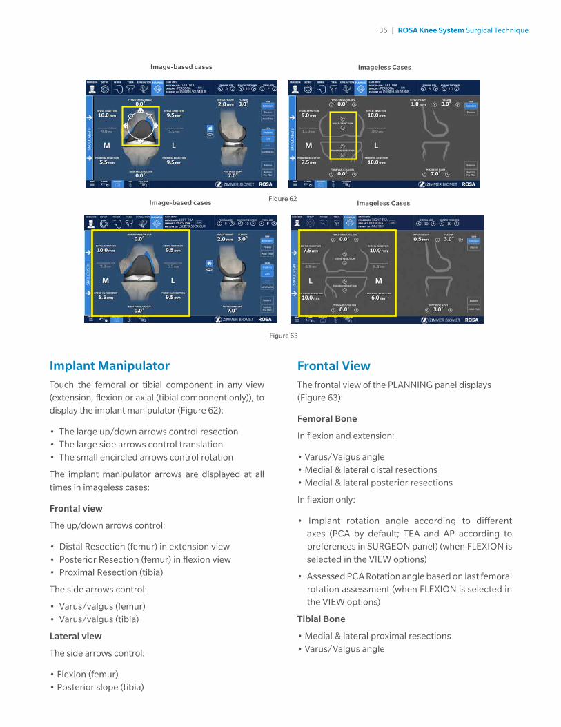
Frontal ViewThe frontal view of the PLANNING panel displays (Figure 63):
Femoral Bone
In flexion and extension:
• Varus/Valgus angle• Medial & lateral distal resections• Medial & lateral posterior resections
In flexion only:
• Implant rotation angle according to different axes (PCA by default; TEA and AP according to preferences in SURGEON panel) (when FLEXION is selected in the VIEW options)
• Assessed PCA Rotation angle based on last femoral rotation assessment (when FLEXION is selected in the VIEW options)
Tibial Bone
• Medial & lateral proximal resections• Varus/Valgus angle
Implant ManipulatorTouch the femoral or tibial component in any view (extension, flexion or axial (tibial component only)), to display the implant manipulator (Figure 62):
• The large up/down arrows control resection• The large side arrows control translation• The small encircled arrows control rotation
The implant manipulator arrows are displayed at all
times in imageless cases:
Frontal view
The up/down arrows control:
• Distal Resection (femur) in extension view• Posterior Resection (femur) in flexion view• Proximal Resection (tibia)
The side arrows control:
• Varus/valgus (femur)• Varus/valgus (tibia)
Lateral view
The side arrows control:
• Flexion (femur)• Posterior slope (tibia)
Image-based cases Imageless Cases
Image-based cases Imageless Cases

36 | ROSA Knee System Surgical Technique
Figure 65
Figure 64
Image-based cases
Imageless CasesNo tibia axial view for imageless cases.
Tibial Axial ViewThe tibia axial view of the PLANNING panel displays (Figure 65):
• Tibial Component - Implant rotation angle
Lateral ViewThe lateral view of the PLANNING panel displays (Figure 64):
• Femoral Bone - Stylus height - Flexion angle• Tibial Bone - Posterior slope angle
For image-based cases, it is possible to rotate the 3D bone model in the lateral view:
• House icon: 3D bone model returns to the original lateral view.
• Rotation icon: Activates the rotation of the 3D bone model. Swipe the touchscreen left or right to turn the 3D bone model.
Image-based cases Imageless Cases

37 | ROSA Knee System Surgical Technique
Figure 66
For imageless cases, the viewing options of the PLANNING panel are (Figure 67):
• EXTENSION: Displays the knee in extension• FLEXION: Displays the knee in flexion• BALANCE: Displays the balance tool• RESTORE PRE-PLAN: Allows to revert to initial plan
(by-default: surgeon’s preferences)
Viewing OptionsFor image-based cases, the viewing options of the PLANNING panel are (Figure 66):
• EXTENSION/FLEXION/AXIAL TIBIA - Displays the knee in extension, flexion or axial view of the tibia• IMPLANTS: Toggles on/off the display of the
implants• AXES: Toggles on/off the display of the axes (only
in FLEXION view) - Implant rotation angle relative to the PCA axis (default axis) - Implant rotation angle relative to the TEA axis (preference-based) - Implant rotation angle relative to the AP axis (preference-based)• LANDMARKS: Toggles on/off the display of the
acquired landmarks• BALANCE: Displays the balance tool• RESTORE PRE-PLAN: Allows to revert to initial plan
(by default: preoperative planning)
Image-based cases Imageless Cases
Figure 67

38 | ROSA Knee System Surgical Technique
After the Optional Femoral Rotation Assessment
Once the femoral rotation assessment is complete, the medial and lateral gaps are no longer split into cuts and space values. Only “Total Gap” will be shown which is the overall gap (Figure 69):
• Extension: The total gap is assessed with the spacer block in place.
• Flexion: The total gap is assessed based on the femoral rotation assessment, which equals the distraction distance plus the planned posterior resection.
Balance ToolBefore the Optional Femoral Rotation Assessment
The balance tool before the optional femoral rotation assessment shows the same information in the EXTENSION and FLEXION views (Figure 68):
• Generic representation of the tibia with medial/lateral identifier
• Component thickness: Total thickness of the femoral and tibial components (with polyethylene)
• Medial and lateral cut values
• Medial and lateral space values
• Sum of the cuts and space on the medial and lateral sides, in flexion and in extension
The space values (laxity) are generated during the knee state evaluation (EVALUATION panel). Space values can only be modified by changes in the knee state evaluation. Cuts values can be adjusted using
bone resections, femoral rotation and implant sizing.
Extension
Flexion
BALANCE tool before optional
femoral rotation assessment
BALANCE tool after optional
femoral rotation assessment
Figure 68 Figure 69

39 | ROSA Knee System Surgical Technique
• Set the rotation of the tibial component.
• Set the implant size of the tibial component.
• Set the medio-lateral positioning of the tibial component.
• Review the overall surgical plan.
After the Femoral Rotation Assessment
Once the femoral rotation assessment is performed (if the option is selected in the SURGEON panel), the surgical flow will come back to the PLANNING panel. If the femoral rotation value following the pull test was applied to the surgical plan, review the following steps:
• In the viewing options, set the VIEW of the knee in FLEXION.
• In the frontal view, review the femoral distal resection and tibial proximal resection.
Posterior Referencing Instrumentation
• In the lateral view, review the posterior bone resection.
• Review the implant size of the femoral component based on the stylus height and anterior bone resection.
Anterior Referencing Instrumentation
• In the lateral view, review the anterior cut based on the stylus height.
• Review the implant size of the femoral component based on the posterior bone resection.
• In the frontal view, review the medio-lateral positioning of the femoral component.
• Review the overall surgical plan.
Note: Parameters in the PLANNING panel influence each other. Make sure to review the overall surgical plan before proceeding to the RESECTIONS drawer.
Note: The BALANCE tool can be used at all times to help perform the surgical plan.
Femoral and Tibial Components PlanningThe initial displayed planning values will be based on the preoperative planning and surgeon’s preferences for image-based cases, or only on the surgeon’s preferences for imageless cases.
• In the implant editor, confirm the implant brand, the femoral and tibial components, as well as the instrumentation preference.
• In the viewing options, set the VIEW of the knee in EXTENSION.
• In the frontal view, set the varus/valgus angle of the femoral and tibial components.
• In the lateral view, set the flexion angle of the femoral component.
• In the lateral view, set the slope angle of the tibial component.
• In the viewing options, set the VIEW of the knee in FLEXION.
• In the frontal view, set the femoral rotation.
• In the frontal view, set the femoral distal resection
and tibial proximal resection.
Posterior Referencing Instrumentation
• In the lateral view, set the posterior bone resection.
• Select the implant size of the femoral component based on the stylus height and anterior bone resection.
Anterior Referencing Instrumentation
• In the lateral view, set the anterior resection based on the stylus height.
• Select the implant size of the femoral component based on the posterior bone resection.
• In the frontal view, set the medio-lateral positioning of the femoral component.
• In the viewing options, set the VIEW of the knee in AXIAL TIBIA.

40 | ROSA Knee System Surgical Technique
RESECTIONS Drawer OverviewThe RESECTIONS drawer of the ROSA Knee Software is used intraoperatively for the surgeon to perform the femoral distal resection, tibial proximal resection, the femoral rotation assessment (optional) and the femoral 4-in-1 resection according to the chosen implant components. Based on the intraoperative planned values, the ROSA robotic arm will move to reach the appropriate positions to execute the surgical plan. The RESECTIONS drawer is accessible from the PLANNING panel on the left of the screen (Figure 70).
Figure 70
Access to the Surgery Drawer from PLANNING
RESECTIONS Drawer

41 | ROSA Knee System Surgical Technique
Checkpoint
• Once the ROSA TKA Cut Guide is installed, place the tip of the ROSA Registration Pointer in the checkpoint (divot near the base of the cut guide) (Figure 72).
• If the checkpoint is unsuccessful, please verify the following and redo the checkpoint:
- Do you have the right ROSA TKA Cut Guide?
- Is the ROSA TKA Cut Guide firmly tightened?
- Has the ROSA Base Reference Frame moved? If this is the case, registration needs to redone.
ROSA TKA Cut Guide Installation and Checkpoint
Cut Guide Installation
• Upon entry in the RESECTIONS drawer, install the required ROSA TKA Cut Guide (implant family A or B) to the ROSA Arm Instrument Interface by firmly tightening the two captive screws by hand (Figure 71).
• Click NEXT to proceed to the checkpoint.
Figure 71
Figure 72

42 | ROSA Knee System Surgical Technique
Figure 75
Collaborative Mode: Robotic Arm to Cut Plane
• Once in collaborative mode, press and hold the foot pedal and apply a gentle force on the ROSA TKA Cut Guide to move the cut guide to the bone for pinning (Figure 75).
Note: The robotic arm at this stage is in planar mode, i.e. its movements are restricted to the femoral cut plane only.
Note: Trackers must be visible at all times during bone tracking.
Femoral Distal Resection
Note: The user can choose to start with either the
femoral or tibial resection.
Select Resection to Perform
• Select the tab for femoral distal resection (Figure 73).
Automatic Mode: Robotic Arm to Cut Plane
• Press and hold the foot pedal to automatically move the robotic arm to the femoral cut plane. Hold until the robotic arm switches to the collaborative mode (Figure 74).
Note: When the robotic unit is in automatic mode, stay clear of the robotic arm and its path to the next position.
Figure 73 Figure 74

43 | ROSA Knee System Surgical Technique
Figure 76
Femoral Distal Resection (cont.)First Pin Installation and Live Cut Values
• Keep the foot pedal pressed and install a first pin in the cut guide.
• Make sure to use the holes labeled FEMUR for pinning.
• When the first pin is installed, confirm that the live cut values are acceptable by clicking YES (Figure 76).
Note: Keep pressing the foot pedal when pinning or drilling in collaborative mode to enable the bone tracking mode, otherwise accuracy may be impacted. Visual and audio notifications are provided if the foot pedal is released in collaborative mode.
Note: The user has to acknowledge cut guide placement by looking at live cut values and deciding whether they are acceptable by clicking on the YES button.
Note: Before performing the resection, it is recommended to verify the cut plane with standard instrumentation, such as the alignment rod and the resection guide (angel wing).

44 | ROSA Knee System Surgical Technique
Figure 77
Figure 78 Figure 79
Disengaging the Cut Guide
• Press and hold the foot pedal and disengage the cut guide by applying a gentle force to pull away the cut guide until the desired position is reached. Then click Close (Figure 79).
• If the cut was not previously validated, the system will ask to validate the cut.
Femoral Distal Resection Validation
Validate the femoral distal resection by placing the validation tool on the cut surface until the user
interface indicates green checkmarks.
Femoral Distal Resection (cont.)Pinning and Bone Resection
• Once the first pin installation has been confirmed along with live cut values, the robot is in stationary mode and the foot pedal can be released. Insert the second pin and an oblique pin (if additional stability is needed).
• It is recommended to use two pins to stabilize the cut guide:two FEMUR pin holes with option to use oblique pin holes (Figure 77).
• Perform the femoral distal resection.
• The resection can be validated before removing the pins. Click the Cut Validation button and position the validation tool on the distal cut. The user interface should show all green checkmarks (Figure 78).
• Once the resection is completed, remove all pins then confirm by clicking YES.
Note: Before disengaging the cut guide, verify that all pins are removed.

45 | ROSA Knee System Surgical Technique
Figure 80
Figure 81
Tibial Proximal ResectionSelect Resection to Perform
• Select the tab for tibial proximal resection (Figure 80).
Automatic Mode: Robotic Arm to Cut Plane
• Press and hold the foot pedal to automatically move the robotic arm to the tibial cut plane. Hold until the robotic arm switches to the collaborative mode (Figure 81).
Note: When the robotic unit is in automatic mode, stay clear of the robotic arm and its path to the next position.
Collaborative Mode: Robotic Arm to Cut Plane
• Once in collaborative mode, press and hold the foot pedal and apply a gentle force on the ROSA cut guide to move the cut guide to the bone for pinning (Figure 82).
Note: The robotic arm at this point is in planar mode, i.e. its movements are restricted to the tibial cut plane only.
Figure 82
46 | ROSA Knee System Surgical Technique
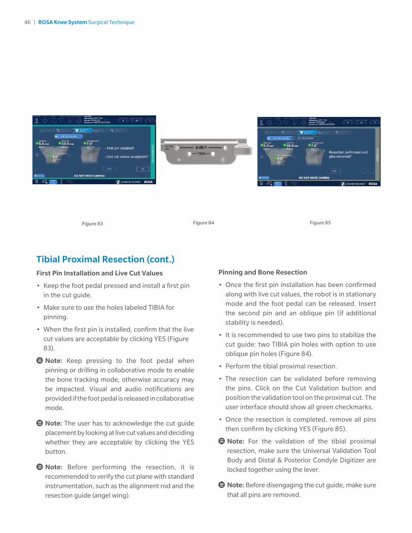
Pinning and Bone Resection
• Once the first pin installation has been confirmed along with live cut values, the robot is in stationary mode and the foot pedal can be released. Insert the second pin and an oblique pin (if additional stability is needed).
• It is recommended to use two pins to stabilize the cut guide: two TIBIA pin holes with option to use oblique pin holes (Figure 84).
• Perform the tibial proximal resection.
• The resection can be validated before removing the pins. Click on the Cut Validation button and position the validation tool on the proximal cut. The user interface should show all green checkmarks.
• Once the resection is completed, remove all pins then confirm by clicking YES (Figure 85).
Note: For the validation of the tibial proximal resection, make sure the Universal Validation Tool Body and Distal & Posterior Condyle Digitizer are locked together using the lever.
Note: Before disengaging the cut guide, make sure
that all pins are removed.
Tibial Proximal Resection (cont.)First Pin Installation and Live Cut Values
• Keep the foot pedal pressed and install a first pin in the cut guide.
• Make sure to use the holes labeled TIBIA for pinning.
• When the first pin is installed, confirm that the live cut values are acceptable by clicking YES (Figure 83).
Note: Keep pressing to the foot pedal when pinning or drilling in collaborative mode to enable the bone tracking mode, otherwise accuracy may be impacted. Visual and audio notifications are provided if the foot pedal is released in collaborative mode.
Note: The user has to acknowledge the cut guide placement by looking at live cut values and deciding whether they are acceptable by clicking the YES button.
Note: Before performing the resection, it is recommended to verify the cut plane with standard instrumentation, such as the alignment rod and the resection guide (angel wing).
Figure 84Figure 83 Figure 85

47 | ROSA Knee System Surgical Technique
Tibial Proximal Resection (cont.)Disengaging the Cut Guide
• Press and hold the foot pedal and disengage the cut guide by applying a gentle force to pull away the cut guide until the desired position is reached.
• If the cut was not previously validated, the system will ask to validate the cut.
Tibial Proximal Resection Validation
Validate the tibial proximal resection by placing the validation tool on the cut surface until the user interface indicates green checkmarks.
Femoral Rotation (Optional)If Femoral Rotation was not selected, proceed to the Femoral 4-in-1 Resection section on page 50.
This option will be accessible only if the femoral rotation tool was included by selecting “Apply to workflow” in the SURGEON panel.
Leg Positioning
• Put the leg in extension (-5° to 20°) (Figure 86).
• Transition to the extension gap assessment will be done automatically.
Figure 86

48 | ROSA Knee System Surgical Technique
Femoral Rotation Assessment
• Put the leg in flexion (95° ± 5°).
• Perform a pull test (manually or with instruments such as a laminar spreader or Zimmer FuZion) to assess the femoral rotation needed to balance the flexion gaps (Figure 88).
• Click CAPTURE to record the femoral rotation value.
Femoral Rotation (Optional) (cont.)Extension Gap Assessment
• Insert a spacer block in the joint and enter the correct value in the software (BEARING THICKNESS).
• Assess the extension gaps by stressing the knee in varus and valgus while keeping the leg in extension (-5° to 20°) (Figure 87).
• Click the X symbol to clear the acquired values.
• Click NEXT to proceed to the pull test.
• Click BACK to return to VALIDATION or CANCEL to return to the RESECTIONS drawer main panel.
Figure 87
Figure 88

49 | ROSA Knee System Surgical Technique
Femoral Rotation (Optional) (cont.)Apply Femoral Rotation to Planning
• Once the femoral rotation has been captured, the value will be displayed according to TEA and PCA axes (Figure 89).
• Three options are then available:
- APPLY: Apply the rotation to the surgical plan
- REDO: Redo the pull test
- DO NOT APPLY: Returns to PLANNING without applying the rotation to the surgical plan
Return to Planning: Balance Tool
• If the femoral rotation is applied to the surgical plan, the software will go back to the PLANNING panel with rotation values displayed, as well as the balance tool (Figure 90).
Figure 89 Figure 90

50 | ROSA Knee System Surgical Technique
Figure 91
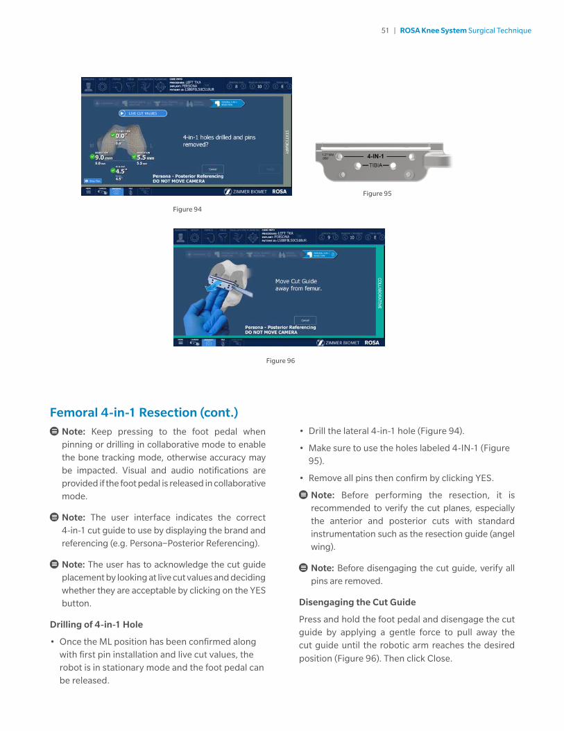
First Pin Installation and Live Cut Values
• Verify the appropriate instrumentation (implant brand and reference; e.g. Persona – Posterior Referencing)
• Verify that the mediolateral (ML) position of the cut guide is correct.
• Keep the foot pedal pressed and install a first pin in the cut guide on the medial side.
• Make sure to use the holes labeled 4-IN-1 for the 1st pin (medial).
• When the first pin is installed, confirm that the live cut values are acceptable by clicking YES (Figure 93).
Femoral 4-in-1 ResectionSelect Resection to Perform
• Select the tab for femoral 4-in-1 resection (Figure 94).
Automatic Mode: Robotic Arm to Femur
• Press and hold the foot pedal to automatically move the robotic arm to the femur (Figure 91). Hold until the robotic arm switches to the collaborative mode.
Collaborative Mode: Robotic Arm to Femur
• Once in collaborative mode, press and hold the foot pedal and apply a gentle force on the ROSA cut guide to move the cut guide to the bone for drilling the 4-in-1 holes (Figure 92).
Note: The robotic arm at this point is in planar mode, i.e. its movements are restricted to the femoral 4-in-1 plane only.
Figure 92 Figure 93
51 | ROSA Knee System Surgical Technique
Figure 96
• Drill the lateral 4-in-1 hole (Figure 94).
• Make sure to use the holes labeled 4-IN-1 (Figure 95).
• Remove all pins then confirm by clicking YES.
Note: Before performing the resection, it is recommended to verify the cut planes, especially the anterior and posterior cuts with standard instrumentation such as the resection guide (angel wing).
Note: Before disengaging the cut guide, verify all pins are removed.
Disengaging the Cut Guide
Press and hold the foot pedal and disengage the cut guide by applying a gentle force to pull away the cut guide until the robotic arm reaches the desired
position (Figure 96). Then click Close.
Femoral 4-in-1 Resection (cont.)
Note: Keep pressing to the foot pedal when pinning or drilling in collaborative mode to enable the bone tracking mode, otherwise accuracy may be impacted. Visual and audio notifications are provided if the foot pedal is released in collaborative mode.
Note: The user interface indicates the correct 4-in-1 cut guide to use by displaying the brand and referencing (e.g. Persona−Posterior Referencing).
Note: The user has to acknowledge the cut guide placement by looking at live cut values and deciding whether they are acceptable by clicking on the YES button.
Drilling of 4-in-1 Hole
• Once the ML position has been confirmed along with first pin installation and live cut values, the robot is in stationary mode and the foot pedal can be released.
Figure 95
Figure 94

52 | ROSA Knee System Surgical Technique
Figure 97
NexGen Implants
• Insert headless pins in the two 4-in-1 holes of the distal femur.
• Place the NexGen 4-in-1 finishing guide onto the distal femur, over the headless pins.
• Position the finishing guide mediolaterally by sliding it on the headless pins.
• Secure the NexGen 4-in-1 finishing guide using two 3.2 mm hex-head screws or trocar pins in the oblique holes and perform bone resections according to the standard surgical technique.
• Remove the bone screws and pins, and subsequently the 4-in-1 cut guide.
Femoral 4-in-1 Resection (cont.)4-in-1 Bone Resections
Note: Before performing the 4-in-1 bone resections, confirm there is no notching using the standard instrumentation such as the resection guide (angel wing).
Persona and Vanguard Implants
• Place the appropriate 4-in-1 cut guide on the distal femur by aligning the two pegs on the back of the 4-in-1 cut guide with the 4-in-1 holes in the distal femur.
• Secure the appropriate 4-in-1 finishing guide using two 3.2mm hex-head screws or trocar pins in the oblique holes and perform bone resections according to the standard surgical technique.
• Remove the bone screws and pins, and subsequently the 4-in-1 cut guide (Figure 97).

53 | ROSA Knee System Surgical Technique
Figure 98
Final Knee Evaluation (Optional)With trial implants in place (or final implants), it is possible to perform a final knee evaluation. Reference the Knee Evaluation section on page 31.
Implant Confirmation Window• Insert trial implants and confirm the following
implant selection (Figure 98):
- Brand
- Femur and Tibial component type and size
- Bearing
• If necessary, changes can be made in the implant selector in the top task bar.

54 | ROSA Knee System Surgical Technique
ShutdownClick on the MENU button on the left of the bottom task bar. Select QUIT to have the following three options:
• Quit and send robotic arm to the park position
• Quit only
• Cancel
Note: When the robotic unit is in automatic mode, stay clear of the robotic arm and its path to the next position.
By quitting the ROSA Knee Software, the user interface will return to the case management application. Click on SHUTDOWN to power down the device.
Note: Wait 10 seconds after the extinction of the touchscreen to turn the power switch of the device to “0”, for the operating system to shut down properly.
Turn the power switch to the “0” position.
Note: To restart the device, wait for at least 10 seconds after shutting down, and for the extinction of the reset button light.
Remove the power cable from the power supply plug.
Disconnect the optical unit from the robotic unit.
Clean the robotic and optical units. For cleaning, disinfecting and sterilization, refer to the ROSA Knee User Manual and Surgical Technique.
Note: All wastes and residues must follow the hospital recycling guidelines.
Device StorageDevice Storage and Protection
At the end of the procedure, the device should be stored in an area fulfilling the storage conditions defined in the technical specifications.
In order to preserve the device, it should be stored in an area where there is no traffic and where it will not be exposed to fluids. The device must not be placed on sloping ground without the assurance of its stability. The immobilization system may be used during storage. During storage, ensure that the touchscreen is folded above the robotic unit so that it is protected in the event of a collision.
Instruments Storage and Protection
The instruments shall remain protected from all impacts during handling and storage. Special care shall be taken for all the instruments because any damage whatsoever may directly affect the registration accuracy and the positioning accuracy of instruments on a planned trajectory.
Postoperative Guide

55 | ROSA Knee System Surgical Technique
ROSA Knee Instruments (All reusable instrumentation needs to be sterilized before each use.)
Component’s Name Part number
Instrument Case Lid 110031221
3.5 mm Hex Head Screwdriver 00-5120-087-00
Universal Validation Tool Body 20-8000-010-06
Distal & Posterior Condyles Digitizer 20-8000-010-17
2 Pins Reference Femur TS3 20-8000-010-33
Offset 2 Pins Reference Right Tibia Size 6 20-8000-010-35
Offset 2 Pins Reference Left Tibia Size 6 20-8000-010-36
NavitrackER Pliers 20-8000-070-05
ROSA Base Reference Frame 20-8020-002-00
ROSA Arm Instrument Interface 20-8020-004-00
ROSA Persona TKA Cut Guide A 20-8020-007-00
ROSA Persona TKA Cut Guide B 20-8020-008-00
ROSA NexGen TKA Cut Guide A 20-8020-009-00
ROSA NexGen TKA Cut Guide B 20-8020-010-00
ROSA Vanguard TKA Cut Guide A 20-8020-011-00
ROSA Vanguard TKA Cut Guide B 20-8020-012-00
ROSA Registration Pointer 20-8020-013-00
ROSA Arm Reference Frame 20-8020-015-00
ROSA Knee Persona Kit 20-8020-060-00
ROSA Knee Persona ID Plate 20-8020-060-01
ROSA Knee NexGen Kit 20-8020-061-00
ROSA Knee NexGen ID Plate 20-8020-061-01
ROSA Knee Vanguard Kit 20-8020-062-00
ROSA Knee Vanguard ID Plate 20-8020-062-01
ROSA Knee Inst Case 20-8020-063-00
ROSA Knee Tray 20-8020-064-00
Instrumentation

56 | ROSA Knee System Surgical Technique
ROSA Knee Disposables
Note: Handle instruments with care. Avoid dropping instruments. Damage to an instrument can have a significant effect on the accuracy of the procedure and consequently, on the postoperative surgical outcome. At the end of the procedure, instruments are placed in their tray for sterilization.
Component’s Name Part number
Disposables for Bone References Installation
Fixed Fluted Pin 3.2x150 mm (non-sterile) 20-8000-000-01
Fixed Fluted Pin 3.2x80 mm (non-sterile) 20-8000-000-02
Fixed Fluted Pin 3.2x150 mm 20-8000-000-10
Fixed Fluted Pin 3.2x80 mm 20-8000-000-11
Disposables for Pinning Cut Guides
Trocar Tipped Drill Pin (2.5 mm hex) 3.2x75 mm (Persona) 00-5901-020-00
CAS 3.2 mm Headless Trocar Drill Pin 20-8000-000-16
Vanguard Quick Release Trocular Pin (Vanguard) 32-486255
Vanguard Sterile Quick Release Drill Pin (Vanguard) 32-486265
Other Disposables
NavitrackER Kit A: Knee 20-8000-000-07
ROSA Robotic Unit Drape 20-8020-080-00
ROSA Arm Drape ROSAS00055
Monitor Drape ROSAS00056

57 | ROSA Knee System Surgical Technique

This material is intended for health care professionals. Distribution to any other recipient is prohibited.
For indications, contraindications, warnings, precautions, potential adverse effects and patient counseling information, see the package insert, reference the ROSA Knee User Manual and Surgical Technique or contact your local representative; visit www.zimmerbiomet.com for additional product information.
Zimmer Biomet does not practice medicine. This technique was developed in conjunction with health care professionals. This document is intended for surgeons and is not intended for laypersons. A written copy of the complete ROSA Knee User Manual and Surgical Technique is available at www.zimmerbiomet.com or from your local representative. Each surgeon should exercise his or her own independent judgment in the diagnosis and treatment of an individual patient, and this information does not purport to replace the comprehensive training surgeons have received. As with all surgical procedures, the technique used in each case will depend on the surgeon’s medical judgment as the best treatment for each patient. Results will vary based on health, weight, activity and other variables. Not all patients are candidates for this product and/or procedure. Caution: Federal (USA) law restricts this device to sale by or on the order of a surgeon. Rx only.
All content herein is protected by copyright, trademarks and other intellectual property rights, as applicable, owned by or licensed to Zimmer Biomet or its affiliates unless otherwise indicated, and must not be redistributed, duplicated or disclosed, in whole or in part, without the express written consent of Zimmer Biomet.
Check for country product clearances and reference product specific instructions for use.
©2020 Zimmer Biomet
2304.1-GLBL-en-REV0120
Authorized RepresentativeZimmer U.K. Ltd. 9 Lancaster Place, South Marston Park, Swindon, Wiltshire SN3 4FP, UK
Legal ManufacturerZimmer CAS75 Queen Street Suite 3300 Montreal (Quebec) H3C 2N6 Canada Tel +1.866.3D.ORTHO or 514.395.8883 EC
www.zimmerbiomet.com
0413
CE mark on a surgical technique is not valid unless there is a CE mark on the product label.