Embed Size (px)
Citation preview
KneesApollo® Knee System Classic condylar knee replacement systemDurasul® Tribological System Highly crosslinked polyethylene that resists wear and agingNatural-Knee® System Anatomic design for superior clinical resultsUniSpacerTM Knee System No bone cuts. No compromises.
Severe Revision/Limb SalvageMOST OptionsTM System Modular knee and hip options for severe bone loss, trauma and revision
HipsAlloclassic® (ZweymüllerTM ) Hip Classic proven design with superior clinical resultsAllofitTM Acetabular Cup System Unique Ridgelock™ surface designed for easy implantation and stabilityApollo® Hip System Designed for optimal results with low-demand patientsAPR® Anatomical Hip System The anatomic solution for patient matchingCLSTM (SpotornoTM ) Hip System The standard of proximal press-fit designConverge® CSTi™ Porous Acetabular Cup System Where technology and experience meetDurasul® Tribological System Highly crosslinked polyethylene that resists wear and agingFracSureTM Hip System A classic design for hip fracturesMetasul® Metal-on-Metal Acetabular System Over 15 years of clinical results & 200,000 implantations worldwideMS-30TM Hip A highly polished cemented stemNatural-HipTM System A comprehensive system with a natural approachPrecedentTM Revision Hip System A better solution for revision hipsSL RevisionTM Hip System A stable revision design with extensive sizes
Upper ExtremitiesAnatomicalTM Shoulder System Multiple adjustments of inclination & retroversion with the potential for precisely restored anatomyGSB® Elbow System A nonconstrained design with 21 years of clinical resultsSelect® Shoulder System TSA and fracture management with offset head options
Centerpulse Orthopedics Inc.9900 Spectrum DriveAustin, Texas 78717
512.432.9900877.768.7349fax: 512.432.9014www.centerpulseorthopedics.com
Products are distributed in Europe by Centerpulse Orthopedics Ltd., Altgasse 44, CH-6340, Baar, Switzerland, 41 41 768 32 32; in Canada by Centerpulse Orthopedics Canada, 265 Bartley Drive, Toronto, Ontario, Canada M4A2N7, (416) 751-8787; in Australia by Centerpulse Australia Pty Ltd., Level 5, 384 Eastern Valley Way, Chatswood, NSW 2067, Australia, 011 (61) 2-9417-7922; and in Japan by Centerpulse Japan K.K., Itopia Eitai Bldg., 7F 1-3-7, Saga, Koto-Ku, Tokyo 135-0031, Japan, 011 (81) 3-3820-7477.
1001-01-032 Rev 9/2003 © 2003 Centerpulse Orthopedics Inc. All rights reserved.
Natural-Knee® II Primary Systemwith Modular Cemented Baseplate OptionAnatomic design for superior clinical results
Implanting trust.
Surgical Technique
Centerpulse OrthopedicsAnatomic design for superior clinical results
Centerpulse OrthopedicsAnatomic design for superior clinical results
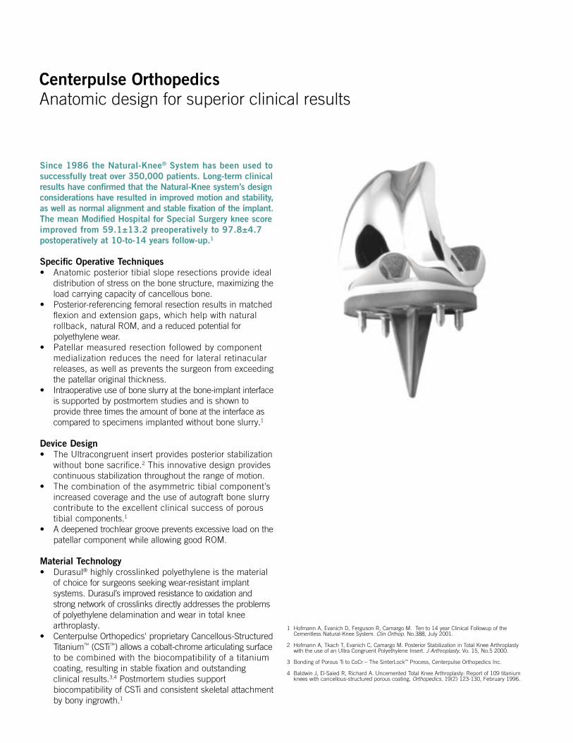
Since 1986 the Natural-Knee® System has been used to successfully treat over 350,000 patients. Long-term clinicalresults have confirmed that the Natural-Knee system’s designconsiderations have resulted in improved motion and stability,as well as normal alignment and stable fixation of the implant.The mean Modified Hospital for Special Surgery knee score improved from 59.1±13.2 preoperatively to 97.8±4.7 postoperatively at 10-to-14 years follow-up.1
Specific Operative Techniques • Anatomic posterior tibial slope resections provide ideal
distribution of stress on the bone structure, maximizing theload carrying capacity of cancellous bone.
• Posterior-referencing femoral resection results in matched flexion and extension gaps, which help with natural rollback, natural ROM, and a reduced potential for polyethylene wear.
• Patellar measured resection followed by componentmedialization reduces the need for lateral retinacular releases, as well as prevents the surgeon from exceeding the patellar original thickness.
• Intraoperative use of bone slurry at the bone-implant interfaceis supported by postmortem studies and is shown to provide three times the amount of bone at the interface as compared to specimens implanted without bone slurry.1
Device Design• The Ultracongruent insert provides posterior stabilization
without bone sacrifice.2 This innovative design provides continuous stabilization throughout the range of motion.
• The combination of the asymmetric tibial component’s increased coverage and the use of autograft bone slurry contribute to the excellent clinical success of porous tibial components.1
• A deepened trochlear groove prevents excessive load on thepatellar component while allowing good ROM.
Material Technology• Durasul® highly crosslinked polyethylene is the material
of choice for surgeons seeking wear-resistant implant systems. Durasul’s improved resistance to oxidation and strong network of crosslinks directly addresses the problems of polyethylene delamination and wear in total knee arthroplasty.
• Centerpulse Orthopedics' proprietary Cancellous-Structured Titanium™ (CSTi™) allows a cobalt-chrome articulating surfaceto be combined with the biocompatibility of a titanium coating, resulting in stable fixation and outstanding clinical results.3,4 Postmortem studies support biocompatibility of CSTi and consistent skeletal attachment by bony ingrowth.1
1 Hofmann A, Evanich D, Ferguson R, Camargo M. Ten to 14 year Clinical Followup of the Cementless Natural-Knee System. Clin Orthop. No.388, July 2001.
2 Hofmann A, Tkach T, Evanich C, Camargo M. Posterior Stabilization in Total Knee Arthroplasty with the use of an Ultra Congruent Polyethylene Insert. J Arthroplasty. Vo. 15, No.5 2000.
3 Bonding of Porous Ti to CoCr – The SinterLock™ Process, Centerpulse Orthopedics Inc.
4 Baldwin J, El-Saied R, Richard A. Uncemented Total Knee Arthroplasty: Report of 109 titanium knees with cancellous-structured porous coating. Orthopedics. 19(2) 123-130, February 1996.
Centerpulse OrthopedicsAnatomic design for superior clinical results
Centerpulse OrthopedicsAnatomic design for superior clinical results
Developed in conjunction with:
Aaron A. Hofmann, MDProfessor of Orthopedic SurgeryUniversity of Utah Medical CenterSalt Lake City, Utah
Kenneth A. Gustke, MDFlorida Orthopaedic InstituteClinical Professor of Orthopedic SurgeryUniversity of South FloridaCollege of MedicineTampa, Florida
Modular Cemented BaseplateSurgeon Consultants:Kenneth Gustke, MDAaron Hofmann, MDWilliam Overdyke, MDBlake Stamper, DO
Design Rationale 1 Restoration of Anatomy 1 Restoration of Normal Alignment 2 Increased Fixation 3Preoperative Planning 3Surgical Technique 4 Bone Cuts 4Surgical Technique Summary 5 Preparing the Femur 5 Preparing the Tibia 6 Preparing the Patella 7Patient Positioning 8Surgical Approach 8Locating the Medullary Canal 9Distal Femoral Cut 10Drill Distal Femoral Holes and Calibrate Femur 12Anterior/Posterior Cuts 13Chamfer Cuts 14Preparing the Proximal Tibia 15Extramedullary Tibial Technique 15Rotation 16Posterior Slope 17Level of Resection 17Proximal Tibia Sizing and Drilling 21 Stemmed/Resurfacing Baseplates 21 Modular Cemented Tibial Baseplates 22Patellar Preparation 25Trial Reduction 28Implanting the Components 30 Patella 30 Stemmed/Resurfacing Baseplates 30 Modular Cemented Tibial Baseplates 31 Tibial Insert 32 Femoral Component 32Postoperative Care 32Posterior Stabilization Option 33Intramedullary Tibial Option 35 Reference Hole 35 Rotation 36 Posterior Slope 37 Level of Resection 38 Tibial Spacer Option 39All-Poly Tibial Option 42 Tibial Preparation 42 Tibial Implantation 42Soft Tissue Balancing 43 Varus Deformity 43 Valgus Deformity 43Ultracongruent and Traditional PosteriorStabilized Component Indications 43Important Information for Surgeon 44Ordering Information 51
Centerpulse OrthopedicsAnatomic design for superior clinical results
Centerpulse OrthopedicsAnatomic design for superior clinical results
Design Rationale
Restoration of AnatomyThe surgery is intended to permit a true resurfacing by referencingthe least-involved portion of the femoral condyle, the least-involved portion of the tibial plateau and the thickest portion of the medial facet of the patella. This restores bony anatomyand the anatomic joint line. Knee rotation testing and computermodeling have shown that the level of resection relative to theamount of bone replaced by the prosthesis on the distal femurplays an important role in knee kinematics and ligament balance.Resection of bone followed by an equal amount of prosthetic replacement will provide the knee with near normal varus-valgusand rotational stability throughout the full range of motion.
The level of the trochlear groove on the femur is anatomically restored by a stepped anterior chamfer cut that allows thebone to be resected and replaced with a deeply grooved femoralcomponent. As a result, patellofemoral joint stability is achieved,making lateral release less frequent and, when required, less extensive. In addition, increased patellofemoral compressiveforces are avoided by maintaining the patellofemoral joint line.
With the Natural-Knee II System, the tibial cut is made parallelto the joint line in the anterior/posterior plane. Since the normalposterior tilt of the tibia is not at a fixed angle (range 4 degreesto 12 degrees), this cut must be adjustable to reproduce eachindividual’s normal posterior slope to avoid camming or laxity during extension and flexion.5 If the posterior slope is fixed or if the tibia is cut perpendicular to the tibial shaft axis, the normal kinematics of the knee will not be simulated.
Furthermore, cutting the tibia parallel to the patient’s natural posterior slope greatly improves the load-carrying capacity of the supporting bone. A 40% improvement in ultimate compressive strength was noted when bone cuts were made parallel to the joint versus those made perpendicular to the tibial shaft axis.6 Clinically, anterior subsidence is avoided if the tibial cut closely matches the anatomic posterior slope.
The proximal tibia is usually 4 mm to 5 mm smaller on the lateral side than on the medial side.7 An asymmetric replacement will provide the best coverage of the proximal tibia and avoid soft tissue impingement. Symmetric replacements however, require either under filling the medial side or overhanging the lateral side.
1
Centerpulse OrthopedicsAnatomic design for superior clinical results
Centerpulse OrthopedicsAnatomic design for superior clinical results
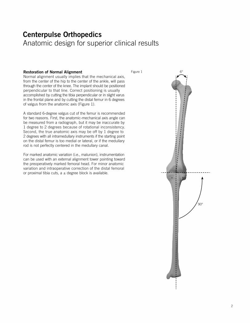
Restoration of Normal AlignmentNormal alignment usually implies that the mechanical axis, from the center of the hip to the center of the ankle, will passthrough the center of the knee. The implant should be positionedperpendicular to that line. Correct positioning is usually accomplished by cutting the tibia perpendicular or in slight varusin the frontal plane and by cutting the distal femur in 6 degreesof valgus from the anatomic axis (Figure 1).
A standard 6-degree valgus cut of the femur is recommendedfor two reasons. First, the anatomic-mechanical axis angle canbe measured from a radiograph, but it may be inaccurate by 1 degree to 2 degrees because of rotational inconsistency. Second, the true anatomic axis may be off by 1 degree to 2 degrees with all intramedullary instruments if the starting pointon the distal femur is too medial or lateral, or if the medullary rod is not perfectly centered in the medullary canal.
For marked anatomic variation (i.e., malunion), instrumentationcan be used with an external alignment tower pointing toward the preoperatively marked femoral head. For minor anatomic variation and intraoperative correction of the distal femoral or proximal tibia cuts, a ± degree block is available.
Figure 1 6°
90°
2
Centerpulse OrthopedicsAnatomic design for superior clinical results
Centerpulse OrthopedicsAnatomic design for superior clinical results
Increased FixationWell-fixed and stable bone-cement-implant interfaces contributesignificantly to the long-term success of the total knee arthroplasty.Porous CSTi improves the bone-cement-implant fixation.8,9,10
Each Natural-Knee II System component is secured with smooth pegs (as opposed to porous-coated pegs) to prevent stress shielding and increase stabilization. The femoral and tibial components are available with either CSTi porous coating or noncoated, microtextured surface finishes.
Tibial fixation of the asymmetric resurfacing and stemmed tibialcomponents is enhanced with two titanium cancellous bone screws that augment the components’ four peripherally-placedpegs and central cruciate stem.7,11 The central stem isrecommended to improve fixation in softer bone (i.e., rheumatoid arthritic patients, osteoporotic females). The resurfacing components provide excellent fixation in hard bone (i.e., osteoarthritic males and patients with prior high tibial osteotomies).12
For improved fixation of the patella, countersinking the 10-mm components 2-mm to 3-mm is recommended.13 Patellar options are offered in four sizes including a 10-mm-thick metal-backed (CSTi) and 10-mm-thick all-poly patella. A 7-mm-thick all-poly patella is available for thinner (less than 20 mm) patellas but should not be countersunk. Patellar component fixation is augmented by three peripherally-placed pegs that fit on a planed flat bed.
Preoperative Planning
Obtain 36-inch, or preferably 52-inch, standing anteroposteriorand lateral radiographs of the extremity as well as a sunrise view of the patella. The entire femur should be visualized to ruleout any structural abnormality, as the distal femoral cut will bereferenced from an intramedullary rod in the medullary canal.If the intramedullary tibial instruments are used, the entire tibiashould be visualized to identify any varus or valgus bowing, andthe appropriate tibial entry point planned. Templating for sizeis most accurate on the lateral radiograph since many patientspresent with a flexion contracture that distorts magnification onthe anteroposterior radiograph. The intraoperative managementof tibial defects is planned using bone graft, cement and/or tibial spacers.
The degree of constraint in the tibial insert may be planned, suchas the use of the ultracongruent insert or traditional posteriorstabilized components for more constraint in patients withposterior cruciate ligament (PCL) deficiency or in the unstable varus or valgus knee.
5 Hofmann A, Bachus K, Wyatt R. Effect of the Tibial Cut on Subsidence Following Total Knee Arthroplasty. Clin Orthop. No. 269, p.63-69, August 1991.
6 Hofmann A, Bachus K, Wyatt R. Effect of the Tibial Cut on Subsidence Following Total Knee Arthroplasty. Clin Orthop. No. 269, p63-69, August 1991.
7 Smith, Jeffrey R., Hofmann, Aaron A. Morphology of the Proximal Tibia in the Arthritic Knee. Centerpulse Orthopedics Inc. Austin, TX 2000.
8 Bachus K et al. Canine and Human Cancellous Bony Ingrowth into Titanium and Cobalt Chrome Porous Coated Plugs Implanted into the Proximal Tibia. Orthopedics Transactions. 1988, 12 (2), p. 380.
9 Leland R, Hofmann A, Chowdhary R. Biocompatibility and Bone Response of Human Cancellous Bone to a Titanium Porous Coated Cobalt Chromium Implant. Society of Biomaterial Meeting, Scottsdale, AZ, 1991.
10 Hofmann A. Response of human cancellous bone to identically structured commercially pure titanium and cobalt chromium alloy porous-coated cylinders. Clinical Materials. 14:101-115. 1993.
11 Hofmann A, et al. Total Knee Replacement using the Natural-Knee System. Techniques in Orthopedics. 1987. 1(4), pp.1-17.
12 Hofmann A. Stemmed versus Resurfacing Tibial Component Total Knee Arthroplasty. Knee Society Interim Meeting, Itasca, Illinios, 1991.
13 Evanich C, Tkach T, von Glinski S, Camargo M, Hofmann A. 6- to 10-year experience using countersunk metal-backed patellas. J Arthroplasty. Vol. 12 No.2 (149-154) 1997.
3
Centerpulse OrthopedicsAnatomic design for superior clinical results
Centerpulse OrthopedicsAnatomic design for superior clinical results
Surgical Technique
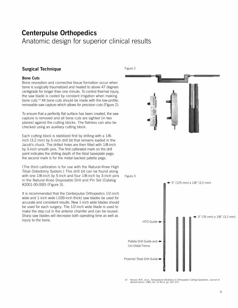
Bone CutsBone resorption and connective tissue formation occur whenbone is surgically traumatized and heated to above 47 degreescentigrade for longer than one minute. To control thermal injury,the saw blade is cooled by constant irrigation when making bone cuts.14 All bone cuts should be made with the low-profile,removable saw capture which allows for precision cuts (Figure 2).
To ensure that a perfectly flat surface has been created, the sawcapture is removed and all bone cuts are sighted (in two planes) against the cutting blocks. The flatness can also be checked using an auxiliary cutting block.
Each cutting block is stabilized first by drilling with a 1/8-inch (3.2 mm) by 5-inch drill bit that remains loaded in the Jacob’s chuck. The drilled holes are then filled with 1/8-inch by 3-inch smooth pins. The first calibrated mark on the drill point indicates the drilling depth of the tibial baseplate pegs; the second mark is for the metal-backed patella pegs.
(The third calibration is for use with the Natural-Knee High Tibial Osteotomy System.) This drill bit can be found along with one 1/8-inch by 5-inch and four 1/8-inch by 3-inch pins in the Natural-Knee Disposable Drill and Pin Set (Catalog #2001-00-000) (Figure 3).
It is recommended that the Centerpulse Orthopedics 1/2-inchwide and 1-inch wide (.039-inch thick) saw blades be used foraccurate and consistent results. New 1-inch wide blades shouldbe used for each surgery. The 1/2-inch wide blade is used tomake the step cut in the anterior chamfer and can be reused.Sharp saw blades will decrease both operating time as well asinjury to the bone.
Figure 3
Figure 2
5” (125 mm) x 1/8” (3.2 mm)
3” (76 mm) x 1/8” (3.2 mm)
HTO Guide
Patella Drill Guide andUni Distal Femur
Proximal Tibial Drill Guide
14 Krause, W.R., et al., Temperature Elevations in Orthopaedic Cutting Operations. Journal of Biomechanics. 1982; Vol. 15 No.4, pp. 267-275.
4
Centerpulse OrthopedicsAnatomic design for superior clinical results
Centerpulse OrthopedicsAnatomic design for superior clinical results
Surgical Technique Summary
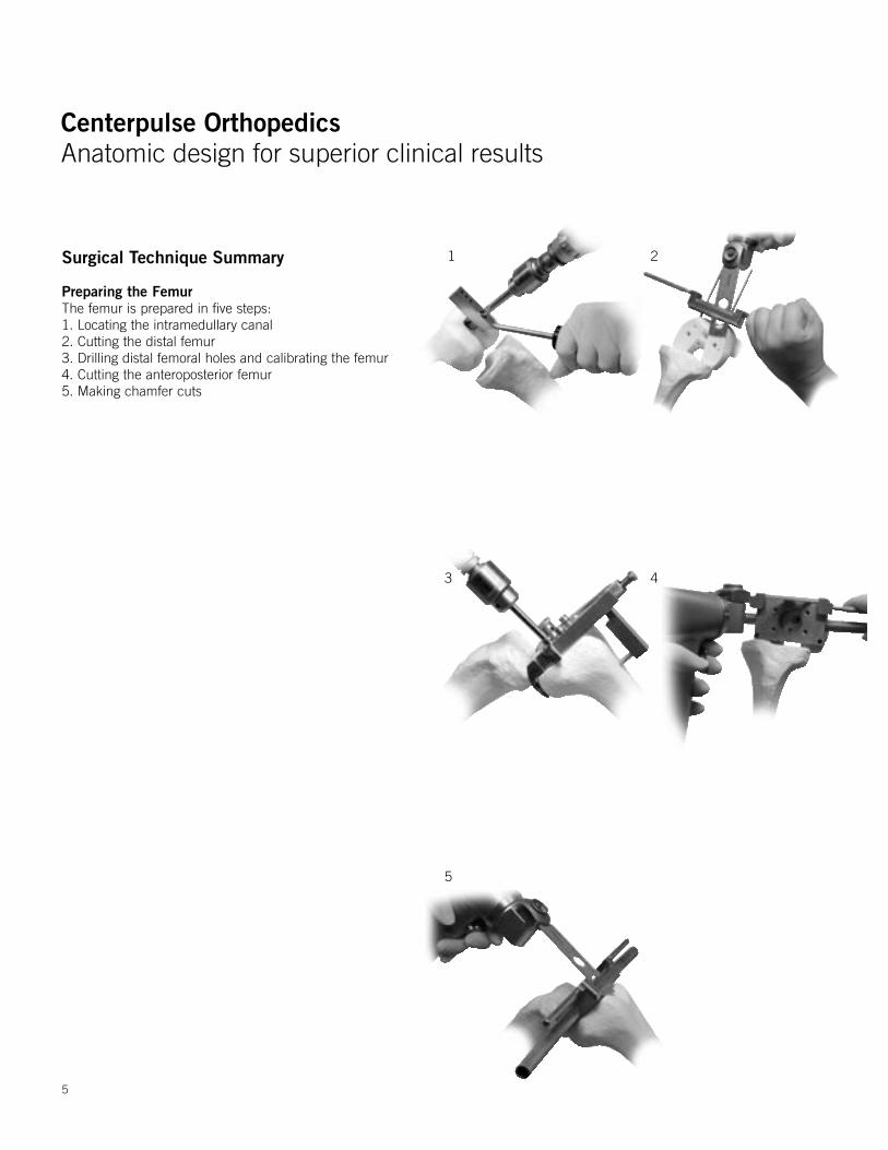
Preparing the FemurThe femur is prepared in five steps:1. Locating the intramedullary canal 2. Cutting the distal femur 3. Drilling distal femoral holes and calibrating the femur 4. Cutting the anteroposterior femur 5. Making chamfer cuts
1 2
3 4
5
5
Centerpulse OrthopedicsAnatomic design for superior clinical results
Centerpulse OrthopedicsAnatomic design for superior clinical results
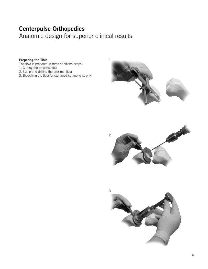
Preparing the TibiaThe tibia is prepared in three additional steps:1. Cutting the proximal tibia2. Sizing and drilling the proximal tibia 3. Broaching the tibia for stemmed components only
1
2
3
6
Centerpulse OrthopedicsAnatomic design for superior clinical results
Centerpulse OrthopedicsAnatomic design for superior clinical results
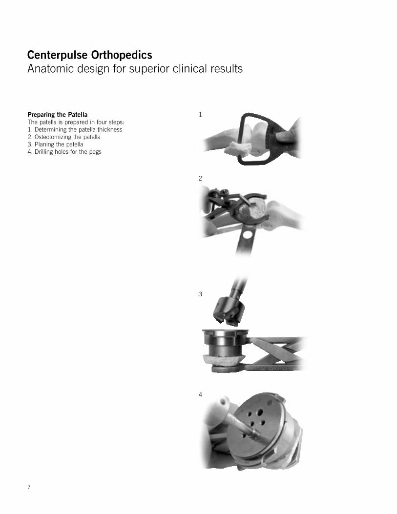
Preparing the PatellaThe patella is prepared in four steps:1. Determining the patella thickness 2. Osteotomizing the patella 3. Planing the patella 4. Drilling holes for the pegs
1
2
3
4
7
Centerpulse OrthopedicsAnatomic design for superior clinical results
Centerpulse OrthopedicsAnatomic design for superior clinical results
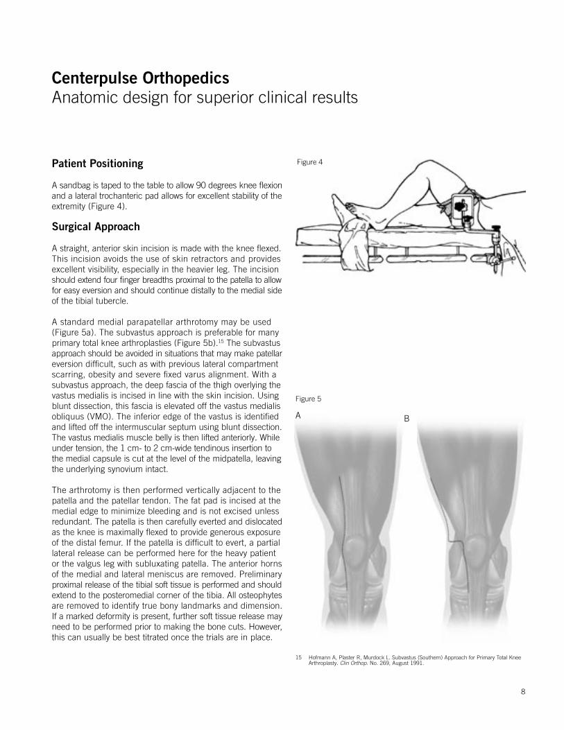
Patient Positioning
A sandbag is taped to the table to allow 90 degrees knee flexionand a lateral trochanteric pad allows for excellent stability of theextremity (Figure 4).
Surgical Approach
A straight, anterior skin incision is made with the knee flexed. This incision avoids the use of skin retractors and provides excellent visibility, especially in the heavier leg. The incision should extend four finger breadths proximal to the patella to allowfor easy eversion and should continue distally to the medial sideof the tibial tubercle.
A standard medial parapatellar arthrotomy may be used (Figure 5a). The subvastus approach is preferable for manyprimary total knee arthroplasties (Figure 5b).15 The subvastus approach should be avoided in situations that may make patellareversion difficult, such as with previous lateral compartment scarring, obesity and severe fixed varus alignment. With a subvastus approach, the deep fascia of the thigh overlying thevastus medialis is incised in line with the skin incision. Usingblunt dissection, this fascia is elevated off the vastus medialisobliquus (VMO). The inferior edge of the vastus is identified and lifted off the intermuscular septum using blunt dissection.The vastus medialis muscle belly is then lifted anteriorly. Whileunder tension, the 1 cm- to 2 cm-wide tendinous insertion to the medial capsule is cut at the level of the midpatella, leaving the underlying synovium intact.
The arthrotomy is then performed vertically adjacent to the patella and the patellar tendon. The fat pad is incised at themedial edge to minimize bleeding and is not excised unlessredundant. The patella is then carefully everted and dislocatedas the knee is maximally flexed to provide generous exposure of the distal femur. If the patella is difficult to evert, a partial lateral release can be performed here for the heavy patient or the valgus leg with subluxating patella. The anterior horns of the medial and lateral meniscus are removed. Preliminary proximal release of the tibial soft tissue is performed and shouldextend to the posteromedial corner of the tibia. All osteophytesare removed to identify true bony landmarks and dimension. If a marked deformity is present, further soft tissue release mayneed to be performed prior to making the bone cuts. However,this can usually be best titrated once the trials are in place.
Figure 4
Figure 5
A B
15 Hofmann A, Plaster R, Murdock L. Subvastus (Southern) Approach for Primary Total Knee Arthroplasty. Clin Orthop. No. 269, August 1991.
8
Centerpulse OrthopedicsAnatomic design for superior clinical results
Centerpulse OrthopedicsAnatomic design for superior clinical results
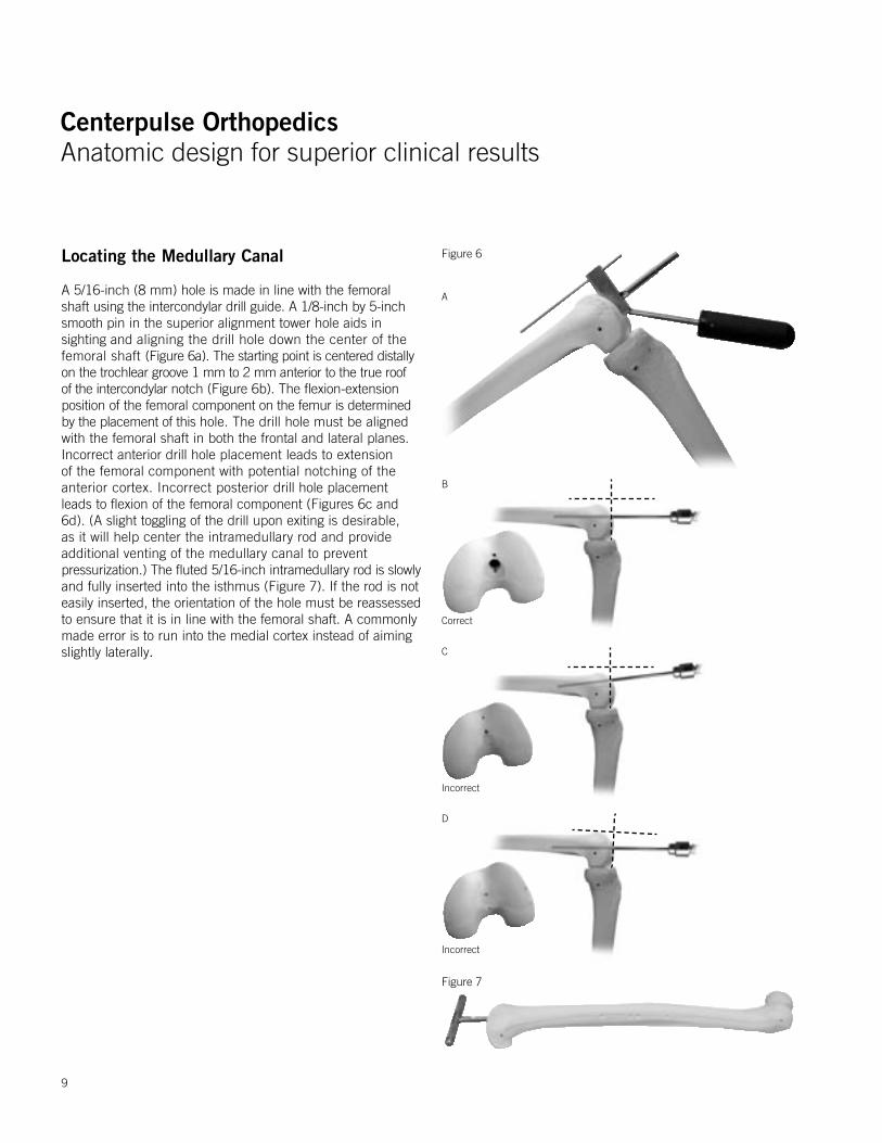
Locating the Medullary Canal
A 5/16-inch (8 mm) hole is made in line with the femoral shaft using the intercondylar drill guide. A 1/8-inch by 5-inch smooth pin in the superior alignment tower hole aids in sighting and aligning the drill hole down the center of the femoral shaft (Figure 6a). The starting point is centered distally on the trochlear groove 1 mm to 2 mm anterior to the true roof of the intercondylar notch (Figure 6b). The flexion-extension position of the femoral component on the femur is determined by the placement of this hole. The drill hole must be aligned with the femoral shaft in both the frontal and lateral planes. Incorrect anterior drill hole placement leads to extension of the femoral component with potential notching of the anterior cortex. Incorrect posterior drill hole placement leads to flexion of the femoral component (Figures 6c and 6d). (A slight toggling of the drill upon exiting is desirable, as it will help center the intramedullary rod and provide additional venting of the medullary canal to preventpressurization.) The fluted 5/16-inch intramedullary rod is slowlyand fully inserted into the isthmus (Figure 7). If the rod is not easily inserted, the orientation of the hole must be reassessed to ensure that it is in line with the femoral shaft. A commonly made error is to run into the medial cortex instead of aiming slightly laterally.
Figure 6
A
B
Correct
C
Incorrect
D
Incorrect
Figure 7
9
Centerpulse OrthopedicsAnatomic design for superior clinical results
Centerpulse OrthopedicsAnatomic design for superior clinical results
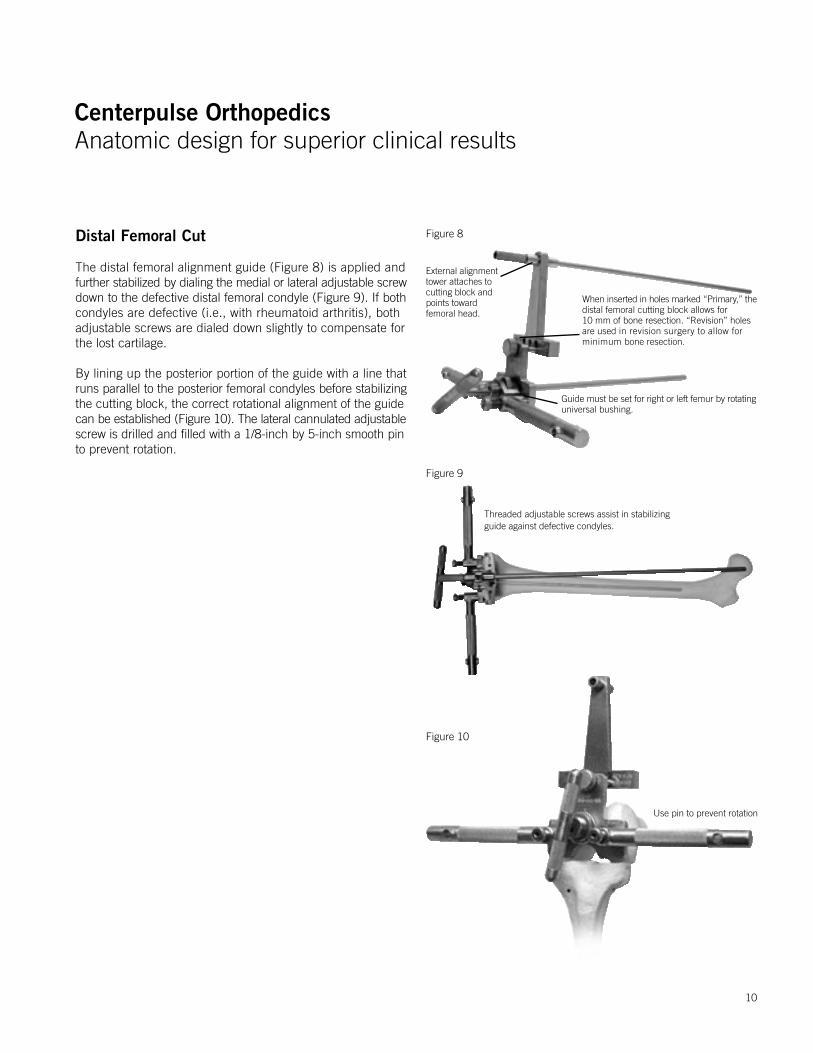
External alignment tower attaches to cutting block and points towardfemoral head.
When inserted in holes marked “Primary,” thedistal femoral cutting block allows for 10 mm of bone resection. “Revision” holes are used in revision surgery to allow for minimum bone resection.
Guide must be set for right or left femur by rotating universal bushing.
Distal Femoral Cut
The distal femoral alignment guide (Figure 8) is applied andfurther stabilized by dialing the medial or lateral adjustable screwdown to the defective distal femoral condyle (Figure 9). If bothcondyles are defective (i.e., with rheumatoid arthritis), both adjustable screws are dialed down slightly to compensate for the lost cartilage.
By lining up the posterior portion of the guide with a line thatruns parallel to the posterior femoral condyles before stabilizingthe cutting block, the correct rotational alignment of the guidecan be established (Figure 10). The lateral cannulated adjustablescrew is drilled and filled with a 1/8-inch by 5-inch smooth pinto prevent rotation.
Figure 8
Threaded adjustable screws assist in stabilizing guide against defective condyles.
Figure 9
Use pin to prevent rotation
Figure 10
10
Centerpulse OrthopedicsAnatomic design for superior clinical results
Centerpulse OrthopedicsAnatomic design for superior clinical results
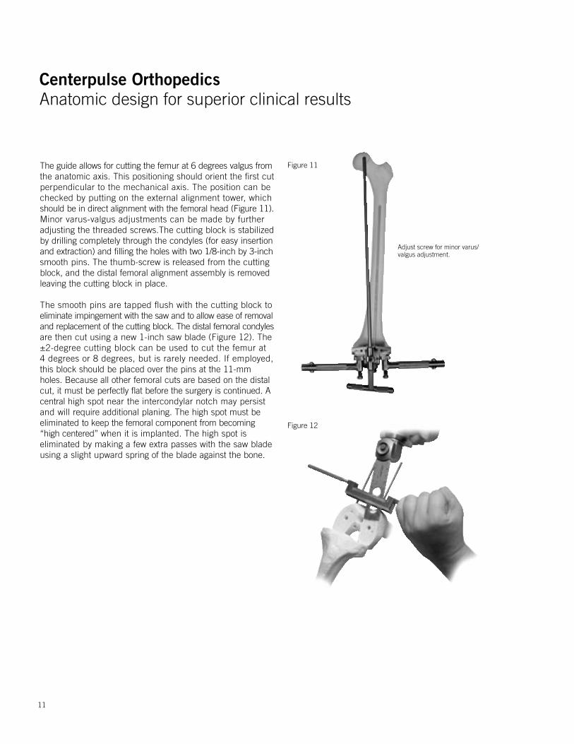
Figure 12
Figure 11The guide allows for cutting the femur at 6 degrees valgus fromthe anatomic axis. This positioning should orient the first cut perpendicular to the mechanical axis. The position can be checked by putting on the external alignment tower, which should be in direct alignment with the femoral head (Figure 11).Minor varus-valgus adjustments can be made by further adjusting the threaded screws.The cutting block is stabilized by drilling completely through the condyles (for easy insertion and extraction) and filling the holes with two 1/8-inch by 3-inchsmooth pins. The thumb-screw is released from the cutting block, and the distal femoral alignment assembly is removedleaving the cutting block in place.
The smooth pins are tapped flush with the cutting block toeliminate impingement with the saw and to allow ease of removaland replacement of the cutting block. The distal femoral condylesare then cut using a new 1-inch saw blade (Figure 12). The ±2-degree cutting block can be used to cut the femur at 4 degrees or 8 degrees, but is rarely needed. If employed, this block should be placed over the pins at the 11-mm holes. Because all other femoral cuts are based on the distal cut, it must be perfectly flat before the surgery is continued. A central high spot near the intercondylar notch may persist and will require additional planing. The high spot must be eliminated to keep the femoral component from becoming “high centered” when it is implanted. The high spot is eliminated by making a few extra passes with the saw blade using a slight upward spring of the blade against the bone.
Adjust screw for minor varus/valgus adjustment.
11
Centerpulse OrthopedicsAnatomic design for superior clinical results
Centerpulse OrthopedicsAnatomic design for superior clinical results
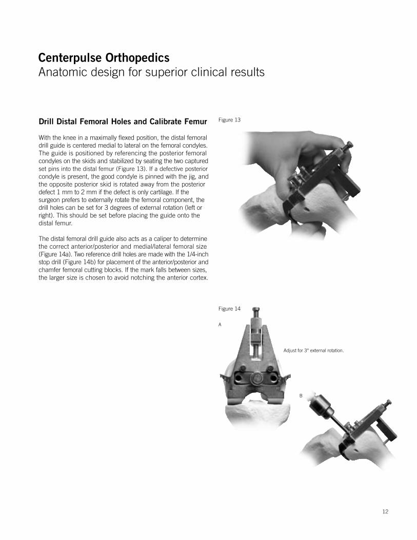
Drill Distal Femoral Holes and Calibrate Femur
With the knee in a maximally flexed position, the distal femoraldrill guide is centered medial to lateral on the femoral condyles.The guide is positioned by referencing the posterior femoral condyles on the skids and stabilized by seating the two capturedset pins into the distal femur (Figure 13). If a defective posteriorcondyle is present, the good condyle is pinned with the jig, andthe opposite posterior skid is rotated away from the posterior defect 1 mm to 2 mm if the defect is only cartilage. If the surgeon prefers to externally rotate the femoral component, the drill holes can be set for 3 degrees of external rotation (left or right). This should be set before placing the guide onto the distal femur.
The distal femoral drill guide also acts as a caliper to determinethe correct anterior/posterior and medial/lateral femoral size(Figure 14a). Two reference drill holes are made with the 1/4-inchstop drill (Figure 14b) for placement of the anterior/posterior andchamfer femoral cutting blocks. If the mark falls between sizes,the larger size is chosen to avoid notching the anterior cortex.
Figure 14
Figure 13
B
Adjust for 3° external rotation.
A
12
Centerpulse OrthopedicsAnatomic design for superior clinical results
Centerpulse OrthopedicsAnatomic design for superior clinical results
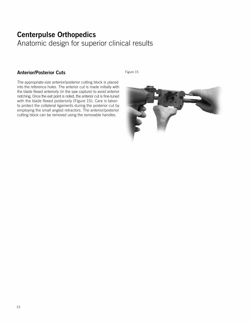
Anterior/Posterior Cuts
The appropriate-size anterior/posterior cutting block is placed into the reference holes. The anterior cut is made initially withthe blade flexed anteriorly (in the saw capture) to avoid anteriornotching. Once the exit point is noted, the anterior cut is fine-tunedwith the blade flexed posteriorly (Figure 15). Care is taken to protect the collateral ligaments during the posterior cut by employing the small angled retractors. The anterior/posterior cutting block can be removed using the removable handles.
Figure 15
13
Centerpulse OrthopedicsAnatomic design for superior clinical results
Centerpulse OrthopedicsAnatomic design for superior clinical results
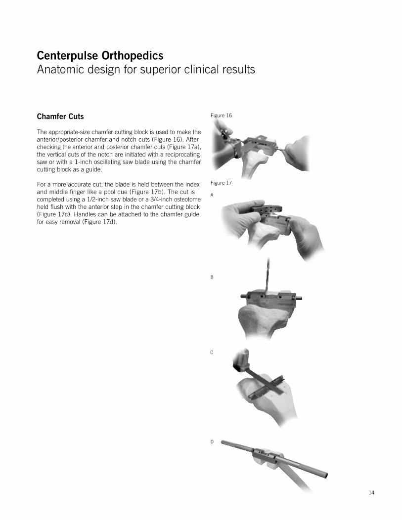
Chamfer Cuts
The appropriate-size chamfer cutting block is used to make theanterior/posterior chamfer and notch cuts (Figure 16). After checking the anterior and posterior chamfer cuts (Figure 17a),the vertical cuts of the notch are initiated with a reciprocating saw or with a 1-inch oscillating saw blade using the chamfer cutting block as a guide.
For a more accurate cut, the blade is held between the indexand middle finger like a pool cue (Figure 17b). The cut iscompleted using a 1/2-inch saw blade or a 3/4-inch osteotomeheld flush with the anterior step in the chamfer cutting block (Figure 17c). Handles can be attached to the chamfer guide for easy removal (Figure 17d).
Figure 16
Figure 17
A
B
C
D
14
Centerpulse OrthopedicsAnatomic design for superior clinical results
Centerpulse OrthopedicsAnatomic design for superior clinical results
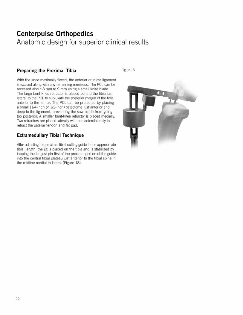
Figure 18Preparing the Proximal Tibia
With the knee maximally flexed, the anterior cruciate ligamentis excised along with any remaining meniscus. The PCL can berecessed about 8 mm to 9 mm using a small knife blade. The large bent-knee retractor is placed behind the tibia just lateral to the PCL to subluxate the posterior margin of the tibia anterior to the femur. The PCL can be protected by placing a small (1/4-inch or 1/2-inch) osteotome just anterior and deep to the ligament, preventing the saw blade from going too posterior. A smaller bent-knee retractor is placed medially. Two retractors are placed laterally with one anterolaterally to retract the patellar tendon and fat pad.
Extramedullary Tibial Technique
After adjusting the proximal tibial cutting guide to the approximatetibial length, the jig is placed on the tibia and is stabilized bytapping the longest pin first of the proximal portion of the guideinto the central tibial plateau just anterior to the tibial spine in the midline medial to lateral (Figure 18).
15
Centerpulse OrthopedicsAnatomic design for superior clinical results
Centerpulse OrthopedicsAnatomic design for superior clinical results
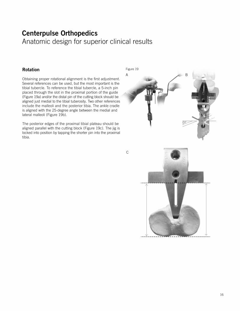
Rotation
Obtaining proper rotational alignment is the first adjustment. Several references can be used, but the most important is thetibial tubercle. To reference the tibial tubercle, a 5-inch pin placed through the slot in the proximal portion of the guide (Figure 19a) and/or the distal pin of the cutting block should bealigned just medial to the tibial tuberosity. Two other references include the malleoli and the posterior tibia. The ankle cradle is aligned with the 25-degree angle between the medial and lateral malleoli (Figure 19b).
The posterior edges of the proximal tibial plateau should bealigned parallel with the cutting block (Figure 19c). The jig islocked into position by tapping the shorter pin into the proximaltibia.
Figure 19
A B
C
25°
16
Centerpulse OrthopedicsAnatomic design for superior clinical results
Centerpulse OrthopedicsAnatomic design for superior clinical results
Figure 21
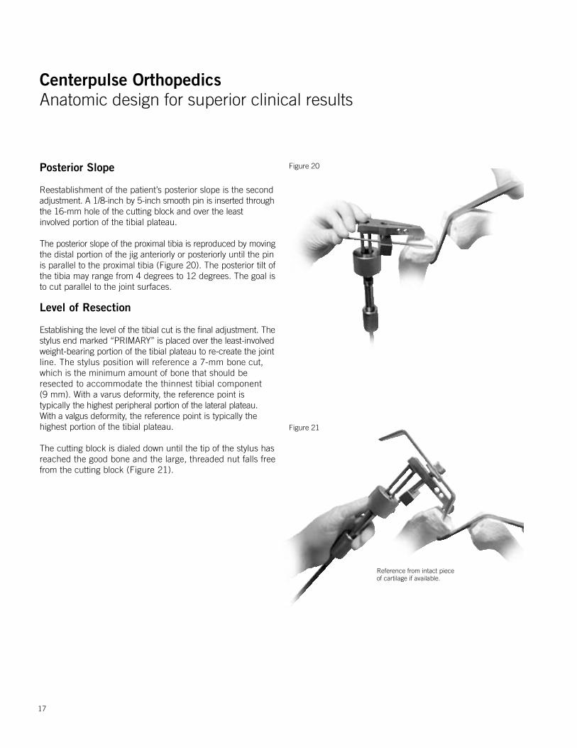
Figure 20Posterior Slope
Reestablishment of the patient’s posterior slope is the second adjustment. A 1/8-inch by 5-inch smooth pin is inserted throughthe 16-mm hole of the cutting block and over the least involved portion of the tibial plateau.
The posterior slope of the proximal tibia is reproduced by movingthe distal portion of the jig anteriorly or posteriorly until the pinis parallel to the proximal tibia (Figure 20). The posterior tilt ofthe tibia may range from 4 degrees to 12 degrees. The goal is to cut parallel to the joint surfaces.
Level of Resection
Establishing the level of the tibial cut is the final adjustment. Thestylus end marked “PRIMARY” is placed over the least-involvedweight-bearing portion of the tibial plateau to re-create the jointline. The stylus position will reference a 7-mm bone cut, which is the minimum amount of bone that should be resected to accommodate the thinnest tibial component (9 mm). With a varus deformity, the reference point is typically the highest peripheral portion of the lateral plateau. With a valgus deformity, the reference point is typically the highest portion of the tibial plateau.
The cutting block is dialed down until the tip of the stylus hasreached the good bone and the large, threaded nut falls freefrom the cutting block (Figure 21).
17
Reference from intact piece of cartilage if available.
Centerpulse OrthopedicsAnatomic design for superior clinical results
Centerpulse OrthopedicsAnatomic design for superior clinical results
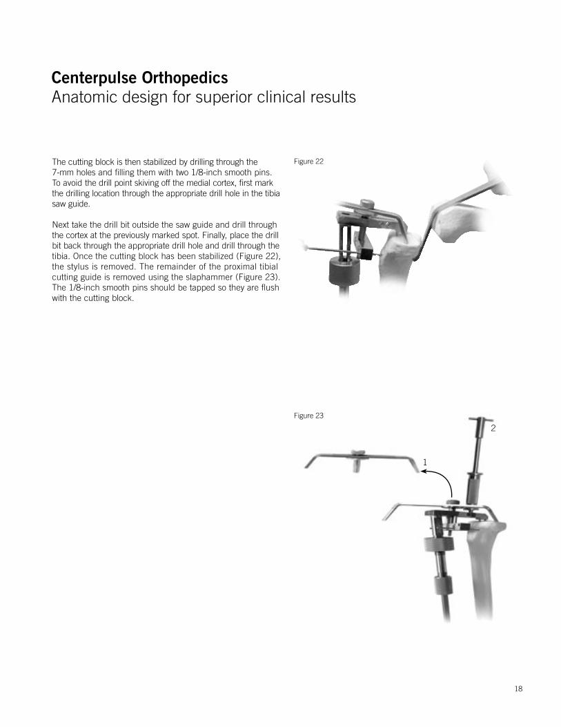
The cutting block is then stabilized by drilling through the 7-mm holes and filling them with two 1/8-inch smooth pins. To avoid the drill point skiving off the medial cortex, first mark the drilling location through the appropriate drill hole in the tibia saw guide.
Next take the drill bit outside the saw guide and drill throughthe cortex at the previously marked spot. Finally, place the drillbit back through the appropriate drill hole and drill through thetibia. Once the cutting block has been stabilized (Figure 22),the stylus is removed. The remainder of the proximal tibial cutting guide is removed using the slaphammer (Figure 23). The 1/8-inch smooth pins should be tapped so they are flush with the cutting block.
Figure 22
Figure 23
1
2
18

Centerpulse OrthopedicsAnatomic design for superior clinical results
Centerpulse OrthopedicsAnatomic design for superior clinical results
Figure 24The tibial alignment checker is then placed on the cutting block.The tip of the rod should fall in the middle of the ankle for aperpendicular cut (Figure 24a). If the patient has an excessiveproximal tibial varus deformity, it is advisable to use the ±2-degree varus/valgus block in the varus mode to allow resection of a more symmetrical wedge of proximal tibia. The alignment rod should still fall within the confines of the ankle joint, although it will be slightly (2 degrees) lateralized (Figure 24b)at the distal tibiofemoral joint.
Most patients will require a minimum of 9 mm of resection to allow use of at least a 9-mm polyethylene insert. The cutting block can be moved down in 2-mm increments to eliminate bone defects and match the thicknesses of available tibial inserts. The small angled knee retractors should be used to protect the medial and lateral collateral ligaments. If preserving the PCL, the PCL should be well protected with the large angled knee retractor and a 1/4-inch osteotome.
A. Perpendicular Cut B. 2-Degree Varus Cut
19
Centerpulse OrthopedicsAnatomic design for superior clinical results
Centerpulse OrthopedicsAnatomic design for superior clinical results
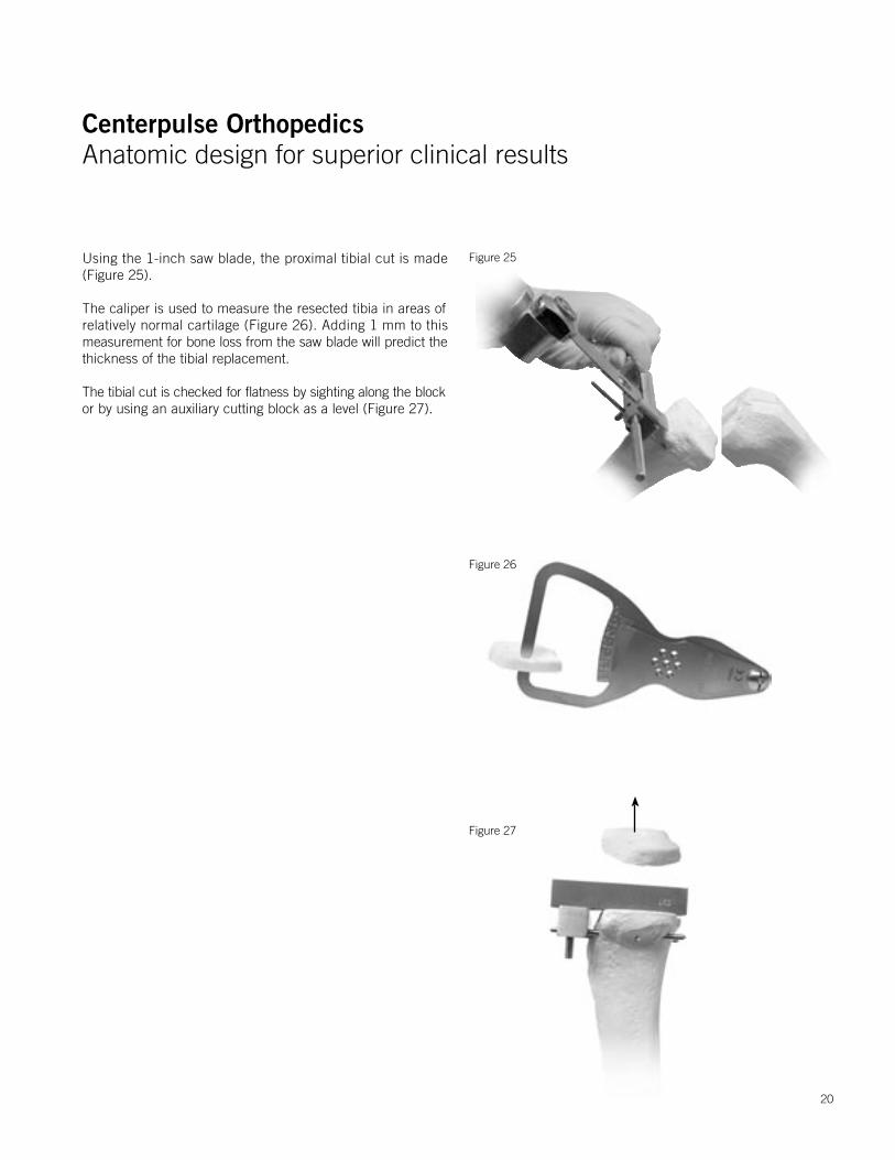
Using the 1-inch saw blade, the proximal tibial cut is made (Figure 25).
The caliper is used to measure the resected tibia in areas of relatively normal cartilage (Figure 26). Adding 1 mm to this measurement for bone loss from the saw blade will predict thethickness of the tibial replacement.
The tibial cut is checked for flatness by sighting along the blockor by using an auxiliary cutting block as a level (Figure 27).
Figure 25
Figure 27
Figure 26
20
Centerpulse OrthopedicsAnatomic design for superior clinical results
Centerpulse OrthopedicsAnatomic design for superior clinical results
Proximal Tibia Sizing and Drilling
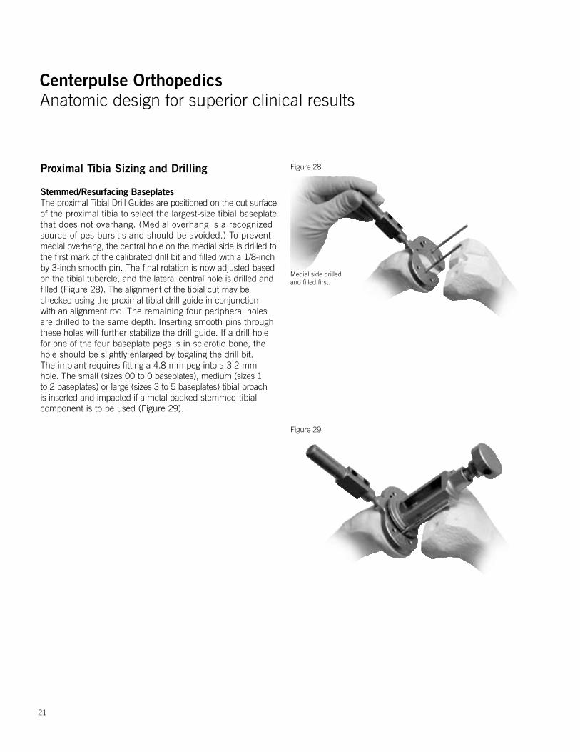
Stemmed/Resurfacing BaseplatesThe proximal Tibial Drill Guides are positioned on the cut surfaceof the proximal tibia to select the largest-size tibial baseplate that does not overhang. (Medial overhang is a recognized source of pes bursitis and should be avoided.) To prevent medial overhang, the central hole on the medial side is drilled tothe first mark of the calibrated drill bit and filled with a 1/8-inchby 3-inch smooth pin. The final rotation is now adjusted basedon the tibial tubercle, and the lateral central hole is drilled andfilled (Figure 28). The alignment of the tibial cut may be checked using the proximal tibial drill guide in conjunction with an alignment rod. The remaining four peripheral holes are drilled to the same depth. Inserting smooth pins through these holes will further stabilize the drill guide. If a drill hole for one of the four baseplate pegs is in sclerotic bone, the hole should be slightly enlarged by toggling the drill bit. The implant requires fitting a 4.8-mm peg into a 3.2-mm hole. The small (sizes 00 to 0 baseplates), medium (sizes 1 to 2 baseplates) or large (sizes 3 to 5 baseplates) tibial broach is inserted and impacted if a metal backed stemmed tibial component is to be used (Figure 29).
Figure 28
Figure 29
Medial side drilled and filled first.
21
Centerpulse OrthopedicsAnatomic design for superior clinical results
Centerpulse OrthopedicsAnatomic design for superior clinical results
Proximal Tibia Sizing and Drilling
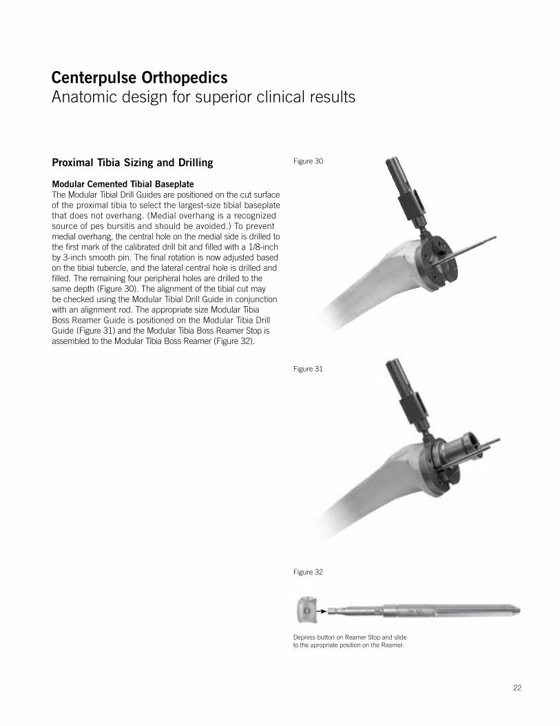
Modular Cemented Tibial Baseplate The Modular Tibial Drill Guides are positioned on the cut surfaceof the proximal tibia to select the largest-size tibial baseplate that does not overhang. (Medial overhang is a recognized source of pes bursitis and should be avoided.) To prevent medial overhang, the central hole on the medial side is drilled tothe first mark of the calibrated drill bit and filled with a 1/8-inchby 3-inch smooth pin. The final rotation is now adjusted basedon the tibial tubercle, and the lateral central hole is drilled andfilled. The remaining four peripheral holes are drilled to the same depth (Figure 30). The alignment of the tibial cut may be checked using the Modular Tibial Drill Guide in conjunction with an alignment rod. The appropriate size Modular Tibia Boss Reamer Guide is positioned on the Modular Tibia Drill Guide (Figure 31) and the Modular Tibia Boss Reamer Stop is assembled to the Modular Tibia Boss Reamer (Figure 32).
Figure 30
Figure 31
22
Figure 32
Depress button on Reamer Stop and slide to the apropriate position on the Reamer.
Centerpulse OrthopedicsAnatomic design for superior clinical results
Centerpulse OrthopedicsAnatomic design for superior clinical results
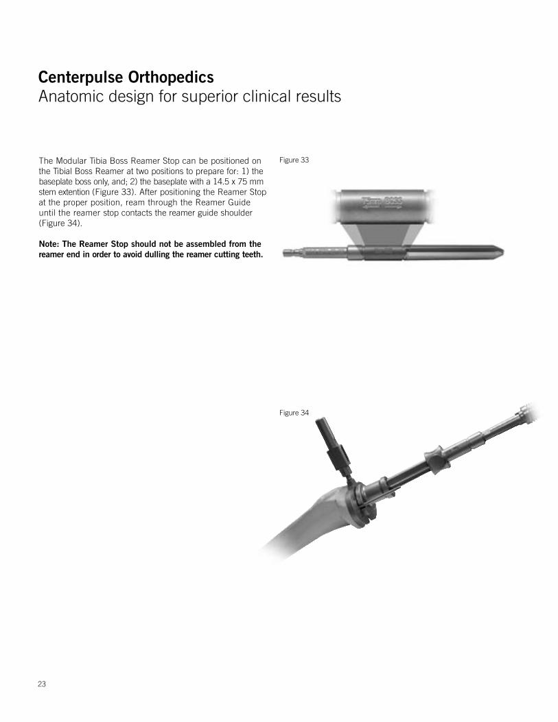
The Modular Tibia Boss Reamer Stop can be positioned on the Tibial Boss Reamer at two positions to prepare for: 1) the baseplate boss only, and; 2) the baseplate with a 14.5 x 75 mm stem extention (Figure 33). After positioning the Reamer Stop at the proper position, ream through the Reamer Guide until the reamer stop contacts the reamer guide shoulder (Figure 34).
Note: The Reamer Stop should not be assembled from the reamer end in order to avoid dulling the reamer cutting teeth.
23
Figure 34
Figure 33
Centerpulse OrthopedicsAnatomic design for superior clinical results
Centerpulse OrthopedicsAnatomic design for superior clinical results
Groove
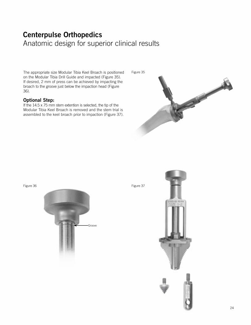
The appropriate size Modular Tibia Keel Broach is positioned on the Modular Tibia Drill Guide and impacted (Figure 35). If desired, 2 mm of press can be achieved by impacting the broach to the groove just below the impaction head (Figure 36).
Optional Step:If the 14.5 x 75 mm stem extention is selected, the tip of the Modular Tibia Keel Broach is removed and the stem trial is assembled to the keel broach prior to impaction (Figure 37).
Figure 36
Figure 35
24
Figure 37

Centerpulse OrthopedicsAnatomic design for superior clinical results
Centerpulse OrthopedicsAnatomic design for superior clinical results
Patellar Preparation
The patella is prepared in the standard fashion by placing theleg in full extension and stabilizing the patella with two invertedtowel clips or by using a rake retractor to keep the patella everted.Soft tissue around the patella is incised down to the insertionof the quadriceps and patellar tendons using an electrocauteryknife. Before making any bone cuts, the maximum thickness of the patella is determined using a caliper (Figure 38). Using the 1/8-inch drill, the highest portion of the medial facet is drilledperpendicular to the articular surface to a depth of approximately12 mm (Figure 39). This will act as a guide for proper medialization of the patella.16 Next, the patella osteotomy guideis used with the stylus set for the desired amount of resection (usually 7 mm). If the patella is very worn, less bone should be resected. A minimum of 10 mm of patella should be retained.
The guide is applied with the jaws at the osteochondral juncturemedial and lateral and the handles of the jig oriented toward thefoot. The jaws should be parallel to the dorsal surface of thepatella. The stylus is positioned over the most prominent pointon the patella. If the 10-mm component is countersunk, it isrecommended that the stylus be positioned at 7 mm of resection (Figure 40).
Figure 38
Figure 39
16 Hofmann A, Tkach, Evanich, Camargo, Zhang. Patellar Component Medialization in Total Knee Arthroplasty. J Arthroplasty. 12(2): 155-160. 1997.
Drill center of medial sagital ridge.
Figure 40
25
Centerpulse OrthopedicsAnatomic design for superior clinical results
Centerpulse OrthopedicsAnatomic design for superior clinical results
26
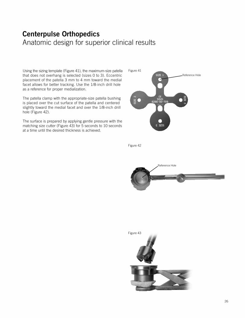
Using the sizing template (Figure 41), the maximum-size patellathat does not overhang is selected (sizes 0 to 3). Eccentric placement of the patella 3 mm to 4 mm toward the medial facet allows for better tracking. Use the 1/8-inch drill hole as a reference for proper medialization.
The patella clamp with the appropriate-size patella bushing is placed over the cut surface of the patella and centered slightly toward the medial facet and over the 1/8-inch drill hole (Figure 42).
The surface is prepared by applying gentle pressure with the matching size cutter (Figure 43) for 5 seconds to 10 seconds at a time until the desired thickness is achieved.
Figure 41
Figure 42
Reference Hole
Reference Hole
Figure 43

Centerpulse OrthopedicsAnatomic design for superior clinical results
Centerpulse OrthopedicsAnatomic design for superior clinical results
This is determined by placing the caliper through the inferior holeof the patella clamp and over the patella bushing (Figure 44).If the 10-mm metal-backed component is selected, it should be recessed 2 mm to 3 mm. (Although it is contraindicated to countersink the 7-mm all-poly patella, the 10-mm all-poly patella may be countersunk if desired.) Example: If the patella thickness was 25 mm, the thickness should be 18 mm after resection. The final thickness of the countersunk area should be 15 mm for use with a 10-mm-thick patella component.
With the clamp still in place, the drill guide is inserted into thepatella bushing. If the metal-backed patella is selected, the threesmaller holes for the patella pegs are drilled with a 1/8-inch by5-inch drill bit and successively filled with 3 x 1/8” smooth pins (Figure 45). Each hole must be drilled and filled before proceeding to the next hole to ensure equal distance between holes. If the all-poly patella component is selected, the all-poly patella stop drill is used to drill the three larger holes. The peg holes are in the same location on all sizes of the patellae.
Separate patella trials are available for 7-mm and 10-mm all-poly patellae as well as 10-mm metal-backed patellae. Due to the wall thickness of the patella bushing, occasionally the next larger size 7-mm all-poly patellar component can be used to maximize cortical bone contact. Make sure to avoid any overhang.
Figure 44
Figure 45
Rotate drill guide in order to have two holes on the medial side.
27
Centerpulse OrthopedicsAnatomic design for superior clinical results
Centerpulse OrthopedicsAnatomic design for superior clinical results
28
Trial Reduction
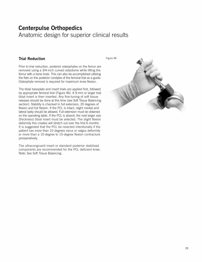
Prior to trial reduction, posterior osteophytes on the femur areremoved using a 3/4-inch curved osteotome while lifting thefemur with a bone hook. This can also be accomplished utilizingthe flats on the posterior condyles of the femoral trial as a guide.Osteophyte removal is required for maximum knee flexion.
The tibial baseplate and insert trials are applied first, followed by appropriate femoral trial (Figure 46). A 9-mm or larger trial tibial insert is then inserted. Any fine-tuning of soft tissue releases should be done at this time (see Soft Tissue Balancing section). Stability is checked in full extension, 20 degrees of flexion and full flexion. If the PCL is intact, slight medial and lateral laxity should be allowed. Full extension must be obtained on the operating table. If the PCL is absent, the next larger size (thickness) tibial insert must be selected. The slight flexion deformity this creates will stretch out over the first 6 months. It is suggested that the PCL be resected intentionally if the patient has more than 10 degrees varus or valgus deformity or more than a 10-degree to 15-degree flexion contracture preoperatively.
The ultracongruent insert or standard posterior stabilized components are recommended for the PCL deficient knee. Note: See Soft Tissue Balancing.
Figure 46
Centerpulse OrthopedicsAnatomic design for superior clinical results
Centerpulse OrthopedicsAnatomic design for superior clinical results
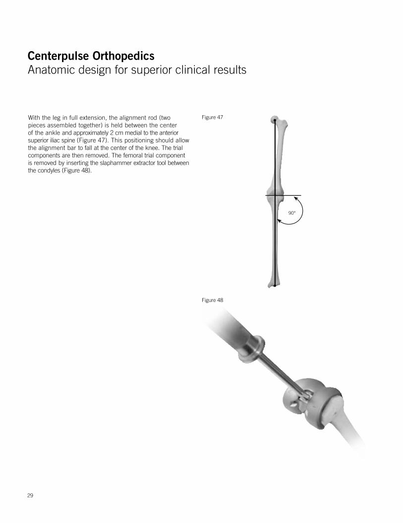
With the leg in full extension, the alignment rod (two pieces assembled together) is held between the center of the ankle and approximately 2 cm medial to the anterior superior iliac spine (Figure 47). This positioning should allow the alignment bar to fall at the center of the knee. The trial components are then removed. The femoral trial component is removed by inserting the slaphammer extractor tool between the condyles (Figure 48).
Figure 47
Figure 48
90°
29
Centerpulse OrthopedicsAnatomic design for superior clinical results
Centerpulse OrthopedicsAnatomic design for superior clinical results
30
Figure 51
Figure 49
Figure 50
Implanting the Components
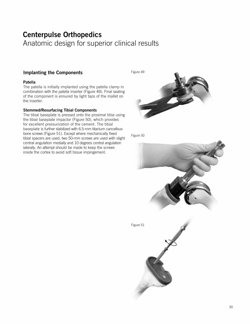
PatellaThe patella is initially implanted using the patella clamp incombination with the patella inserter (Figure 49). Final seatingof the component is ensured by light taps of the mallet onthe inserter.
Stemmed/Resurfacing Tibial Components The tibial baseplate is pressed onto the proximal tibia using the tibial baseplate impactor (Figure 50), which provides for excellent pressurization of the cement. The tibial baseplate is further stabilized with 6.5-mm titanium cancellous bone screws (Figure 51). Except where mechanically fixed tibial spacers are used, two 50-mm screws are used with slight central angulation medially and 10 degrees central angulation laterally. An attempt should be made to keep the screws inside the cortex to avoid soft tissue impingement.
Centerpulse OrthopedicsAnatomic design for superior clinical results
Centerpulse OrthopedicsAnatomic design for superior clinical results
31
Implanting The Components
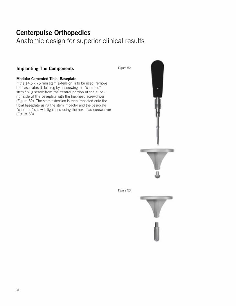
Modular Cemented Tibial Baseplate If the 14.5 x 75 mm stem extension is to be used, remove the baseplate’s distal plug by unscrewing the “captured” stem / plug screw from the central portion of the supe-rior side of the baseplate with the hex-head screwdriver (Figure 52). The stem extension is then impacted onto the tibial baseplate using the stem impactor and the baseplate “captured” screw is tightened using the hex-head screwdriver (Figure 53).
Figure 52
Figure 53
Centerpulse OrthopedicsAnatomic design for superior clinical results
Centerpulse OrthopedicsAnatomic design for superior clinical results
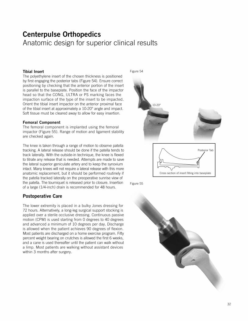
Tibial InsertThe polyethylene insert of the chosen thickness is positioned by first engaging the posterior tabs (Figure 54). Ensure correctpositioning by checking that the anterior portion of the insert is parallel to the baseplate. Position the face of the impactor head so that the CONG, ULTRA or PS marking faces the impaction surface of the type of the insert to be impacted. Orient the tibial insert impactor on the anterior proximal faceof the tibial insert at approximately a 10-20° angle and impact.Soft tissue must be cleared away to allow for easy insertion.
Femoral ComponentThe femoral component is implanted using the femoral impactor (Figure 55). Range of motion and ligament stability are checked again.
The knee is taken through a range of motion to observe patellatracking. A lateral release should be done if the patella tends totrack laterally. With the outside-in technique, the knee is flexedto titrate any release that is needed. Attempts are made to savethe lateral superior geniculate artery and to keep the synoviumintact. Many knees will not require a lateral release with this moreanatomic replacement, but it should be performed routinely if the patella tracked laterally on the preoperative sunrise view ofthe patella. The tourniquet is released prior to closure. Insertionof a large (1/4-inch) drain is recommended for 48 hours.
Postoperative Care
The lower extremity is placed in a bulky Jones dressing for 72 hours. Alternatively, a long-leg surgical support stocking is applied over a sterile occlusive dressing. Continuous passive motion (CPM) is used starting from 0 degrees to 40 degrees and advanced a minimum of 10 degrees per day. Discharge is allowed when the patient achieves 90 degrees of flexion. Most patients are discharged on a home exercise program. Fiftypercent weight bearing on crutches is allowed the first 6 weeks,and a cane is used thereafter until the patient can walk withouta limp. Most patients are walking without assistant devices within 3 months after surgery.
Figure 54
Figure 55
Cross section of insert fitting into baseplate
Posterior Tab
10-20°
32
Centerpulse OrthopedicsAnatomic design for superior clinical results
Centerpulse OrthopedicsAnatomic design for superior clinical results
Figure 57
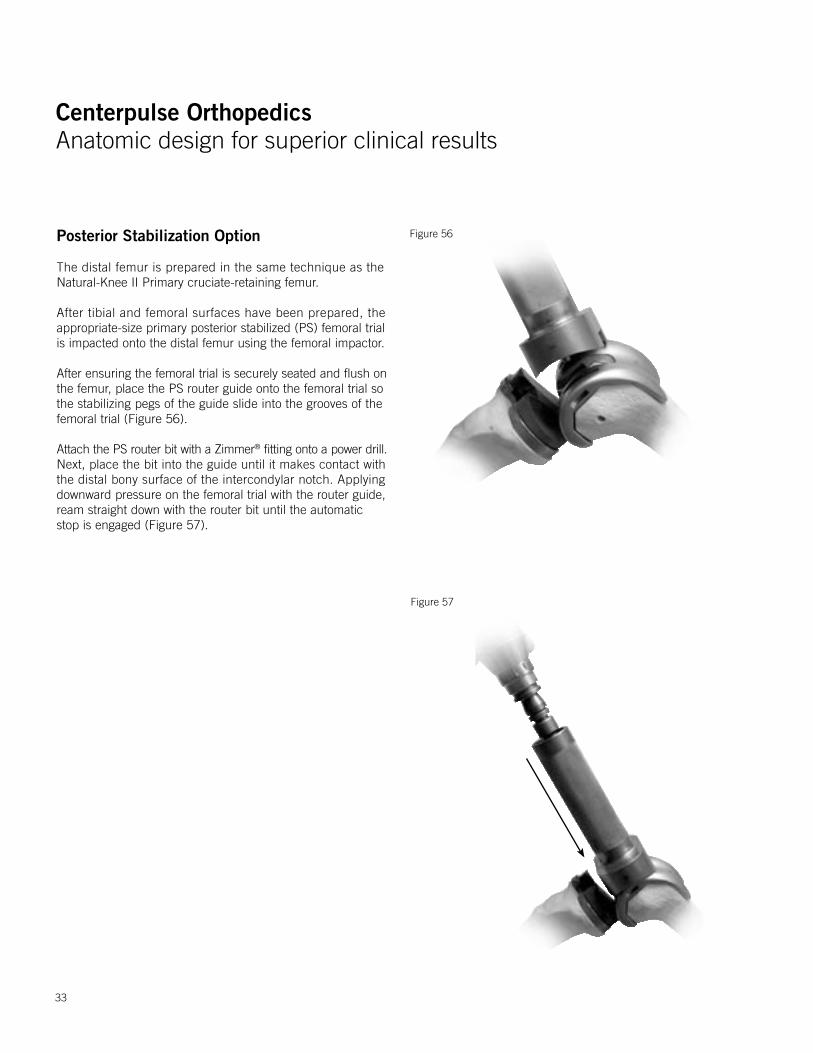
Figure 56Posterior Stabilization Option
The distal femur is prepared in the same technique as the Natural-Knee II Primary cruciate-retaining femur.
After tibial and femoral surfaces have been prepared, the appropriate-size primary posterior stabilized (PS) femoral trial is impacted onto the distal femur using the femoral impactor.
After ensuring the femoral trial is securely seated and flush onthe femur, place the PS router guide onto the femoral trial so the stabilizing pegs of the guide slide into the grooves of the femoral trial (Figure 56).
Attach the PS router bit with a Zimmer® fitting onto a power drill.Next, place the bit into the guide until it makes contact with the distal bony surface of the intercondylar notch. Applying downward pressure on the femoral trial with the router guide, ream straight down with the router bit until the automatic stop is engaged (Figure 57).
33
Centerpulse OrthopedicsAnatomic design for superior clinical results
Centerpulse OrthopedicsAnatomic design for superior clinical results
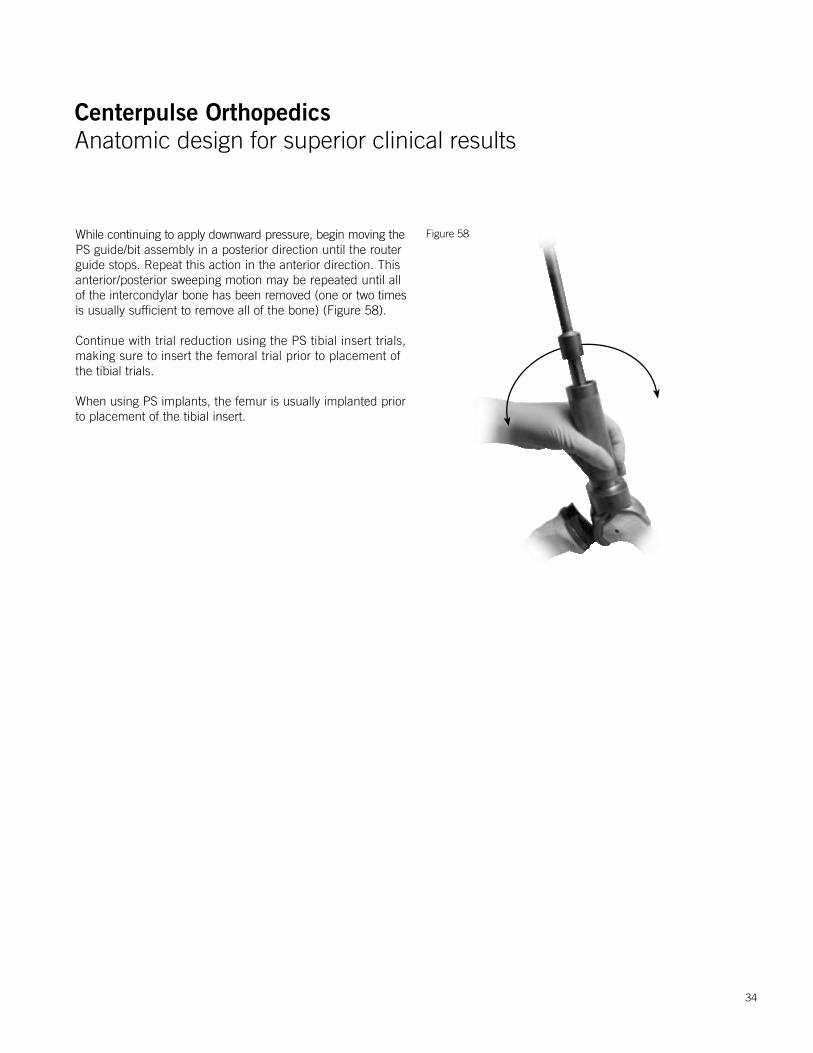
While continuing to apply downward pressure, begin moving thePS guide/bit assembly in a posterior direction until the router guide stops. Repeat this action in the anterior direction. This anterior/posterior sweeping motion may be repeated until allof the intercondylar bone has been removed (one or two timesis usually sufficient to remove all of the bone) (Figure 58).
Continue with trial reduction using the PS tibial insert trials, making sure to insert the femoral trial prior to placement of the tibial trials.
When using PS implants, the femur is usually implanted prior to placement of the tibial insert.
Figure 58
34
Centerpulse OrthopedicsAnatomic design for superior clinical results
Centerpulse OrthopedicsAnatomic design for superior clinical results
Figure 60
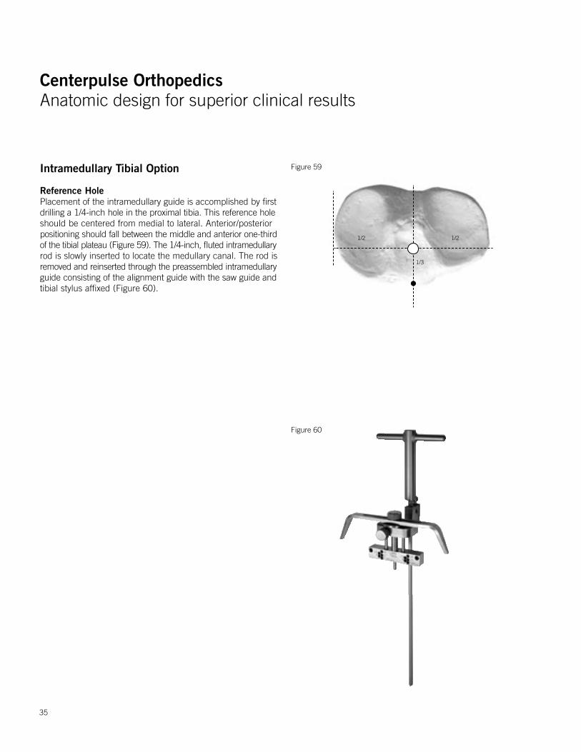
Figure 59Intramedullary Tibial Option
Reference HolePlacement of the intramedullary guide is accomplished by firstdrilling a 1/4-inch hole in the proximal tibia. This reference holeshould be centered from medial to lateral. Anterior/posterior positioning should fall between the middle and anterior one-thirdof the tibial plateau (Figure 59). The 1/4-inch, fluted intramedullaryrod is slowly inserted to locate the medullary canal. The rod isremoved and reinserted through the preassembled intramedullaryguide consisting of the alignment guide with the saw guide andtibial stylus affixed (Figure 60).
35
1/2 1/2
1/3
Centerpulse OrthopedicsAnatomic design for superior clinical results
Centerpulse OrthopedicsAnatomic design for superior clinical results
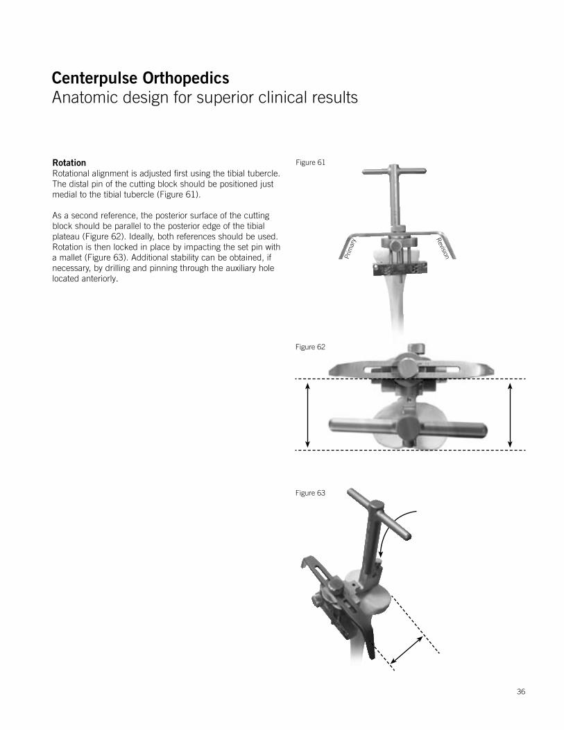
RotationRotational alignment is adjusted first using the tibial tubercle. The distal pin of the cutting block should be positioned just medial to the tibial tubercle (Figure 61).
As a second reference, the posterior surface of the cutting block should be parallel to the posterior edge of the tibial plateau (Figure 62). Ideally, both references should be used. Rotation is then locked in place by impacting the set pin with a mallet (Figure 63). Additional stability can be obtained, if necessary, by drilling and pinning through the auxiliary hole located anteriorly.
Figure 63
Figure 62
Figure 61
Prim
ary R
evision
36
Centerpulse OrthopedicsAnatomic design for superior clinical results
Centerpulse OrthopedicsAnatomic design for superior clinical results
Primary
Rev
isio
n
Figure 65
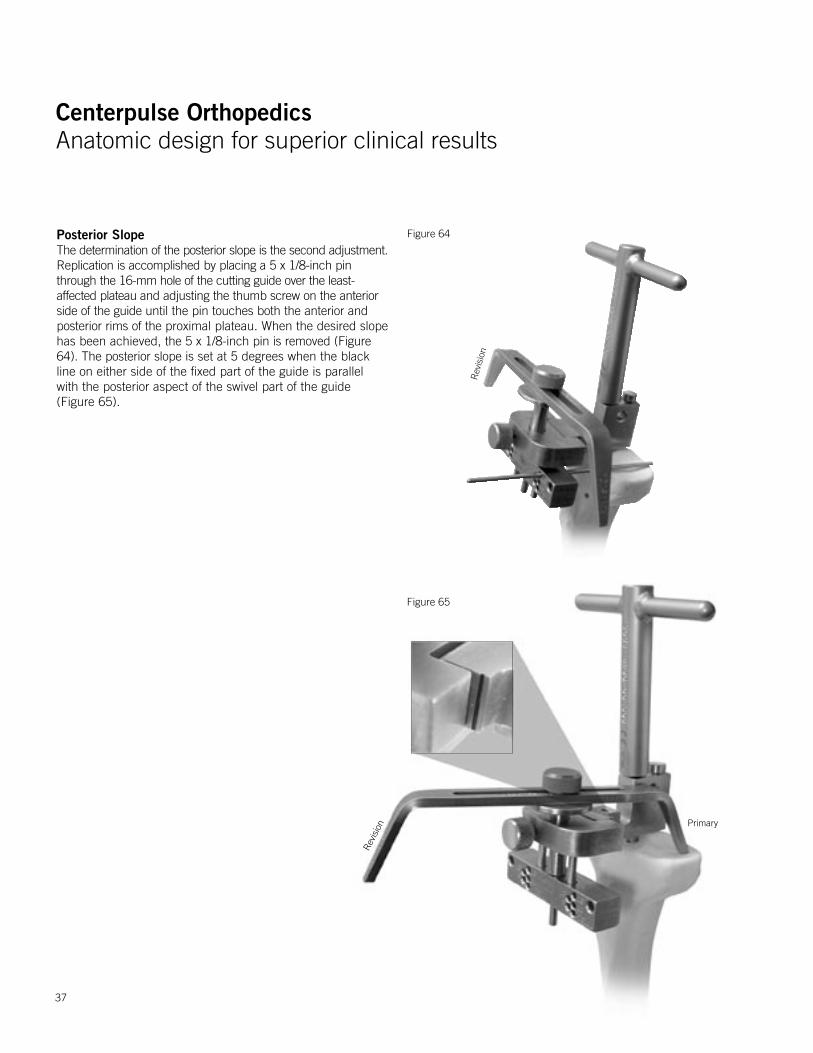
Posterior SlopeThe determination of the posterior slope is the second adjustment.Replication is accomplished by placing a 5 x 1/8-inch pin through the 16-mm hole of the cutting guide over the least-affected plateau and adjusting the thumb screw on the anterior side of the guide until the pin touches both the anterior and posterior rims of the proximal plateau. When the desired slope has been achieved, the 5 x 1/8-inch pin is removed (Figure 64). The posterior slope is set at 5 degrees when the black line on either side of the fixed part of the guide is parallel with the posterior aspect of the swivel part of the guide (Figure 65).
Figure 64
Rev
isio
n
37
Centerpulse OrthopedicsAnatomic design for superior clinical results
Centerpulse OrthopedicsAnatomic design for superior clinical results
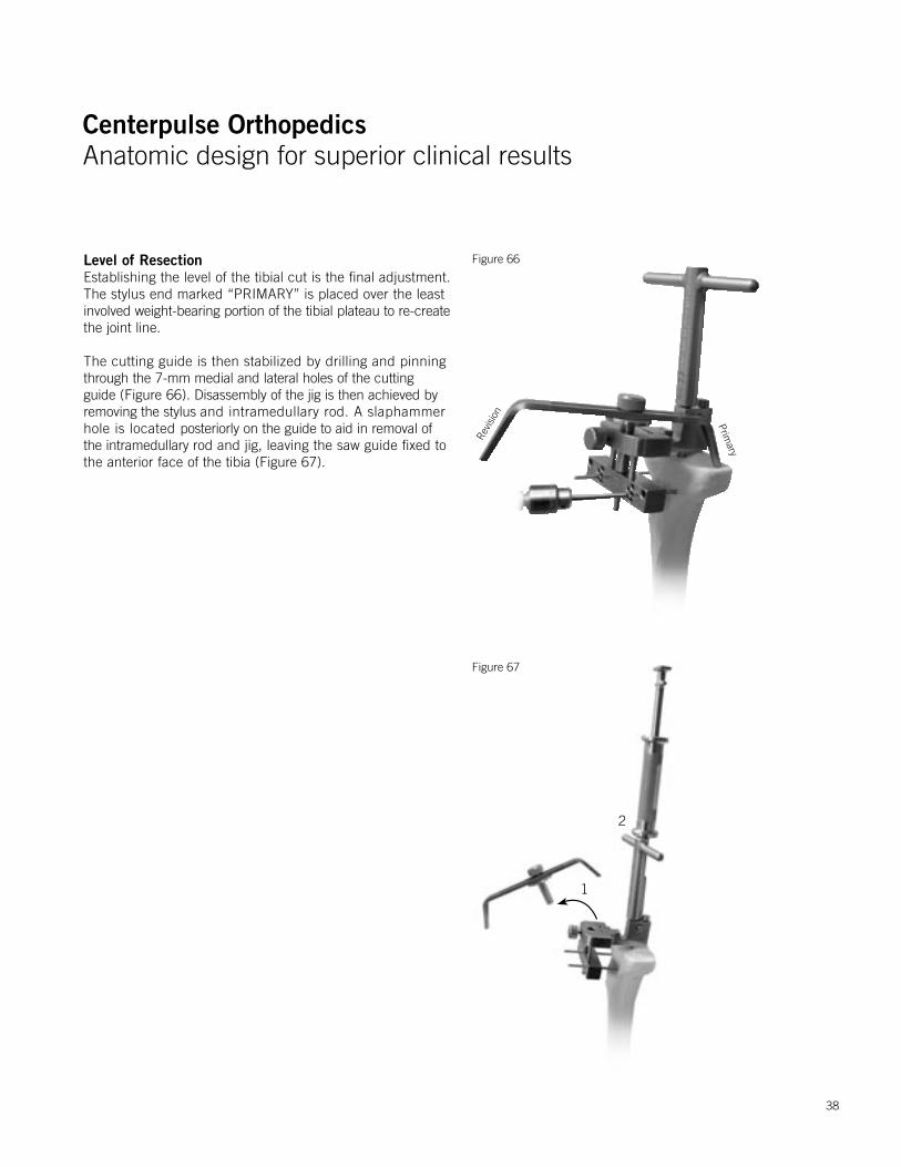
Level of ResectionEstablishing the level of the tibial cut is the final adjustment. The stylus end marked “PRIMARY” is placed over the least involved weight-bearing portion of the tibial plateau to re-createthe joint line.
The cutting guide is then stabilized by drilling and pinning through the 7-mm medial and lateral holes of the cutting guide (Figure 66). Disassembly of the jig is then achieved by removing the stylus and intramedullary rod. A slaphammer hole is located posteriorly on the guide to aid in removal of the intramedullary rod and jig, leaving the saw guide fixed to the anterior face of the tibia (Figure 67).
Figure 66
Figure 67
Primary
Revis
ion
1
2
38
Centerpulse OrthopedicsAnatomic design for superior clinical results
Centerpulse OrthopedicsAnatomic design for superior clinical results
Figure 69
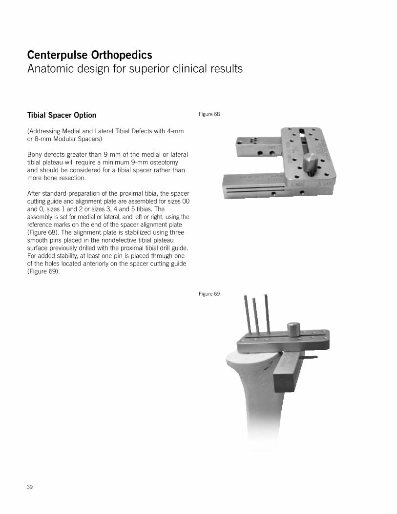
Tibial Spacer Option
(Addressing Medial and Lateral Tibial Defects with 4-mm or 8-mm Modular Spacers)
Bony defects greater than 9 mm of the medial or lateral tibial plateau will require a minimum 9-mm osteotomy and should be considered for a tibial spacer rather than more bone resection.
After standard preparation of the proximal tibia, the spacer cutting guide and alignment plate are assembled for sizes 00and 0, sizes 1 and 2 or sizes 3, 4 and 5 tibias. The assembly is set for medial or lateral, and left or right, using the reference marks on the end of the spacer alignment plate (Figure 68). The alignment plate is stabilized using three smooth pins placed in the nondefective tibial plateau surface previously drilled with the proximal tibial drill guide. For added stability, at least one pin is placed through one of the holes located anteriorly on the spacer cutting guide (Figure 69).
Figure 68
39
Centerpulse OrthopedicsAnatomic design for superior clinical results
Centerpulse OrthopedicsAnatomic design for superior clinical results
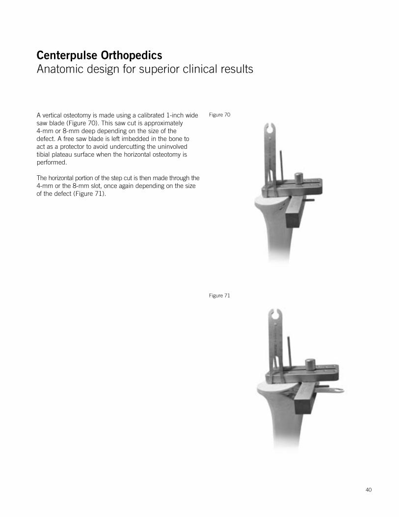
A vertical osteotomy is made using a calibrated 1-inch widesaw blade (Figure 70). This saw cut is approximately 4-mm or 8-mm deep depending on the size of the defect. A free saw blade is left imbedded in the bone to act as a protector to avoid undercutting the uninvolved tibial plateau surface when the horizontal osteotomy is performed.
The horizontal portion of the step cut is then made through the4-mm or the 8-mm slot, once again depending on the size of the defect (Figure 71).
Figure 70
Figure 71
40
Centerpulse OrthopedicsAnatomic design for superior clinical results
Centerpulse OrthopedicsAnatomic design for superior clinical results
Figure 73
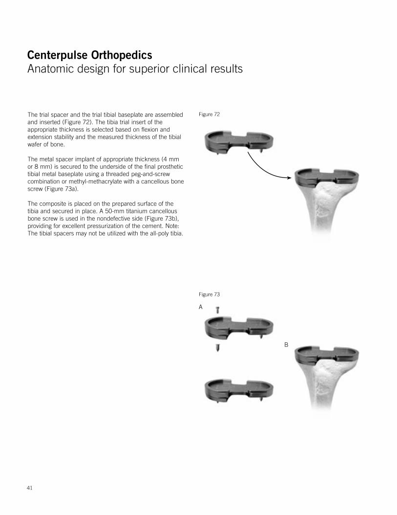
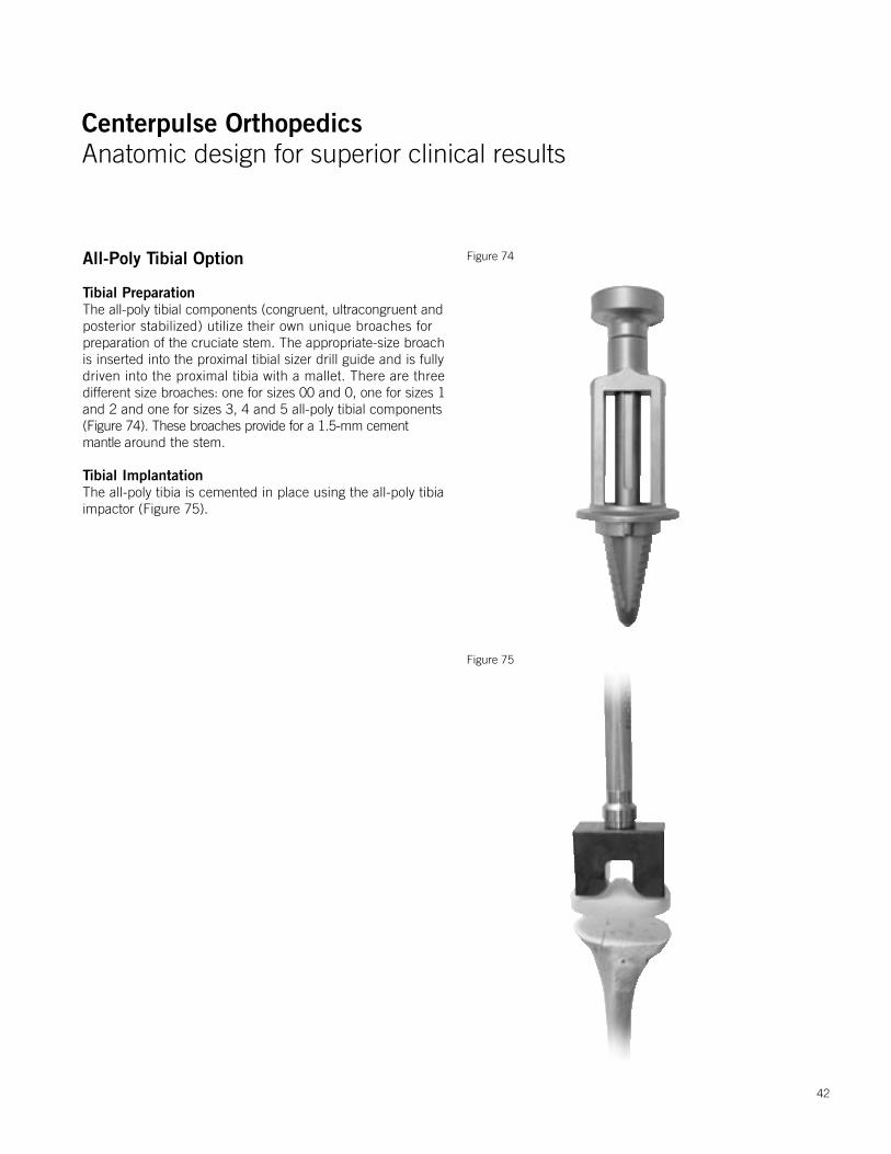
Figure 72The trial spacer and the trial tibial baseplate are assembled and inserted (Figure 72). The tibia trial insert of the appropriate thickness is selected based on flexion and extension stability and the measured thickness of the tibial wafer of bone.
The metal spacer implant of appropriate thickness (4 mm or 8 mm) is secured to the underside of the final prosthetic tibial metal baseplate using a threaded peg-and-screw combination or methyl-methacrylate with a cancellous bone screw (Figure 73a).
The composite is placed on the prepared surface of the tibia and secured in place. A 50-mm titanium cancellous bone screw is used in the nondefective side (Figure 73b), providing for excellent pressurization of the cement. Note: The tibial spacers may not be utilized with the all-poly tibia.
A
B
41
Centerpulse OrthopedicsAnatomic design for superior clinical results
Centerpulse OrthopedicsAnatomic design for superior clinical results
All-Poly Tibial Option
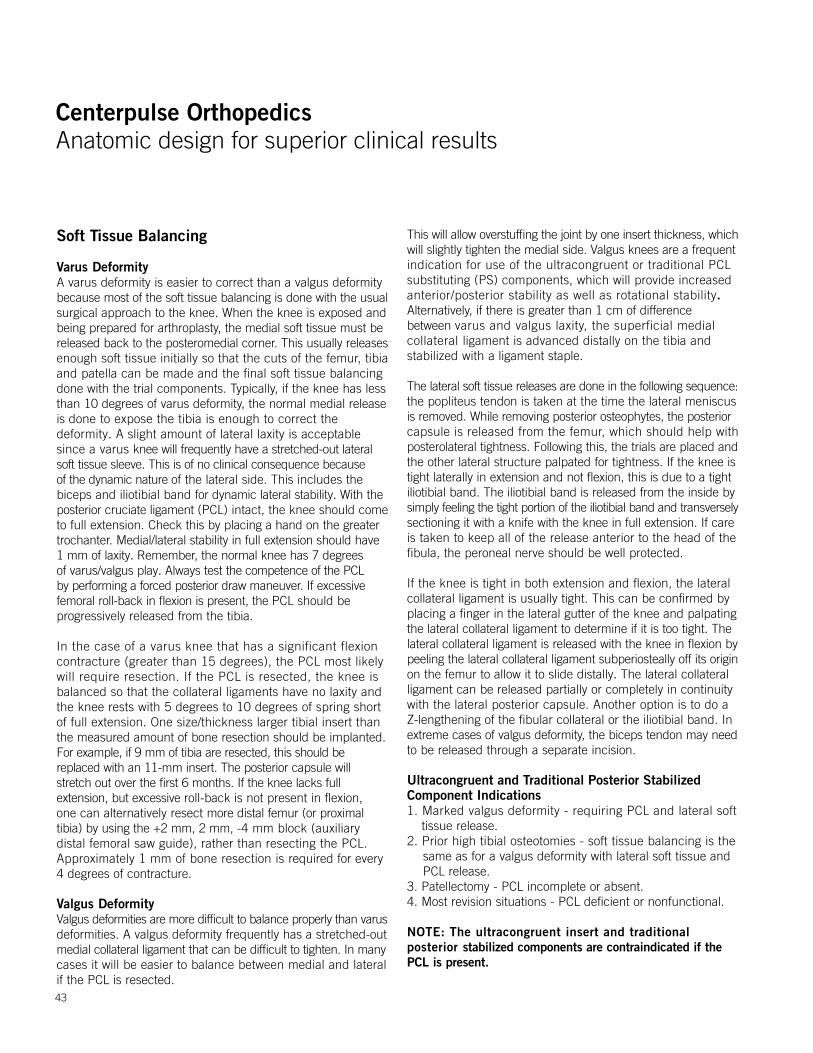
Tibial PreparationThe all-poly tibial components (congruent, ultracongruent andposterior stabilized) utilize their own unique broaches forpreparation of the cruciate stem. The appropriate-size broach is inserted into the proximal tibial sizer drill guide and is fullydriven into the proximal tibia with a mallet. There are three different size broaches: one for sizes 00 and 0, one for sizes 1and 2 and one for sizes 3, 4 and 5 all-poly tibial components (Figure 74). These broaches provide for a 1.5-mm cement mantle around the stem.
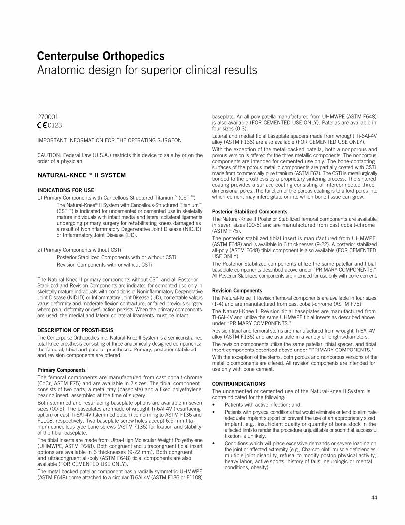
Tibial ImplantationThe all-poly tibia is cemented in place using the all-poly tibia impactor (Figure 75).
Figure 74
Figure 75
42
Centerpulse OrthopedicsAnatomic design for superior clinical results
Centerpulse OrthopedicsAnatomic design for superior clinical results
Soft Tissue Balancing
Varus DeformityA varus deformity is easier to correct than a valgus deformity because most of the soft tissue balancing is done with the usualsurgical approach to the knee. When the knee is exposed andbeing prepared for arthroplasty, the medial soft tissue must bereleased back to the posteromedial corner. This usually releasesenough soft tissue initially so that the cuts of the femur, tibia and patella can be made and the final soft tissue balancing done with the trial components. Typically, if the knee has lessthan 10 degrees of varus deformity, the normal medial releaseis done to expose the tibia is enough to correct the deformity. A slight amount of lateral laxity is acceptable since a varus knee will frequently have a stretched-out lateral soft tissue sleeve. This is of no clinical consequence because of the dynamic nature of the lateral side. This includes the biceps and iliotibial band for dynamic lateral stability. With the posterior cruciate ligament (PCL) intact, the knee should come to full extension. Check this by placing a hand on the greater trochanter. Medial/lateral stability in full extension should have 1 mm of laxity. Remember, the normal knee has 7 degrees of varus/valgus play. Always test the competence of the PCL by performing a forced posterior draw maneuver. If excessive femoral roll-back in flexion is present, the PCL should be progressively released from the tibia.
In the case of a varus knee that has a significant flexion contracture (greater than 15 degrees), the PCL most likely will require resection. If the PCL is resected, the knee is balanced so that the collateral ligaments have no laxity and the knee rests with 5 degrees to 10 degrees of spring shortof full extension. One size/thickness larger tibial insert thanthe measured amount of bone resection should be implanted.For example, if 9 mm of tibia are resected, this should be replaced with an 11-mm insert. The posterior capsule will stretch out over the first 6 months. If the knee lacks full extension, but excessive roll-back is not present in flexion, one can alternatively resect more distal femur (or proximal tibia) by using the +2 mm, 2 mm, -4 mm block (auxiliary distal femoral saw guide), rather than resecting the PCL. Approximately 1 mm of bone resection is required for every 4 degrees of contracture.
Valgus DeformityValgus deformities are more difficult to balance properly than varusdeformities. A valgus deformity frequently has a stretched-outmedial collateral ligament that can be difficult to tighten. In manycases it will be easier to balance between medial and lateral if the PCL is resected.
This will allow overstuffing the joint by one insert thickness, whichwill slightly tighten the medial side. Valgus knees are a frequentindication for use of the ultracongruent or traditional PCL substituting (PS) components, which will provide increased anterior/posterior stability as well as rotational stability. Alternatively, if there is greater than 1 cm of difference between varus and valgus laxity, the superficial medial collateral ligament is advanced distally on the tibia and stabilized with a ligament staple.
The lateral soft tissue releases are done in the following sequence:the popliteus tendon is taken at the time the lateral meniscus is removed. While removing posterior osteophytes, the posteriorcapsule is released from the femur, which should help withposterolateral tightness. Following this, the trials are placed andthe other lateral structure palpated for tightness. If the knee istight laterally in extension and not flexion, this is due to a tightiliotibial band. The iliotibial band is released from the inside bysimply feeling the tight portion of the iliotibial band and transverselysectioning it with a knife with the knee in full extension. If careis taken to keep all of the release anterior to the head of the fibula, the peroneal nerve should be well protected.
If the knee is tight in both extension and flexion, the lateral collateral ligament is usually tight. This can be confirmed byplacing a finger in the lateral gutter of the knee and palpatingthe lateral collateral ligament to determine if it is too tight. Thelateral collateral ligament is released with the knee in flexion bypeeling the lateral collateral ligament subperiosteally off its originon the femur to allow it to slide distally. The lateral collateral ligament can be released partially or completely in continuity with the lateral posterior capsule. Another option is to do a Z-lengthening of the fibular collateral or the iliotibial band. Inextreme cases of valgus deformity, the biceps tendon may needto be released through a separate incision.
Ultracongruent and Traditional Posterior Stabilized Component Indications1. Marked valgus deformity - requiring PCL and lateral soft
tissue release.2. Prior high tibial osteotomies - soft tissue balancing is the
same as for a valgus deformity with lateral soft tissue and PCL release.
3. Patellectomy - PCL incomplete or absent.4. Most revision situations - PCL deficient or nonfunctional.
NOTE: The ultracongruent insert and traditional posterior stabilized components are contraindicated if the PCL is present.
43
Centerpulse OrthopedicsAnatomic design for superior clinical results
Centerpulse OrthopedicsAnatomic design for superior clinical results
IMPORTANT INFORMATION FOR THE OPERATING SURGEON
CAUTION: Federal Law (U.S.A.) restricts this device to sale by or on theorder of a physician.
NATURAL-KNEE ® II SYSTEM
INDICATIONS FOR USE1) Primary Components with Cancellous-Structured Titanium™ (CSTi™) The Natural-Knee® II System with Cancellous-Structured Titanium™
(CSTi™) is indicated for uncemented or cemented use in skeletallymature individuals with intact medial and lateral collateral ligamentsundergoing primary surgery for rehabilitating knees damaged as a result of Noninflammatory Degenerative Joint Disease (NIDJD) or Inflammatory Joint Disease (IJD).
2) Primary Components without CSTi Posterior Stabilized Components with or without CSTi Revision Components with or without CSTi
The Natural-Knee II primary components without CSTi and all Posterior Stabilized and Revision Components are indicated for cemented use only inskeletally mature individuals with conditions of Noninflammatory DegenerativeJoint Disease (NIDJD) or Inflammatory Joint Disease (IJD), correctable valgusvarus deformity and moderate flexion contracture, or failed previous surgerywhere pain, deformity or dysfunction persists. When the primary componentsare used, the medial and lateral collateral ligaments must be intact.
DESCRIPTION OF PROSTHESISThe Centerpulse Orthopedics Inc. Natural-Knee II System is a semiconstrained total knee prosthesis consisting of three anatomically designed components: the femoral, tibial and patellar prostheses. Primary, posterior stabilized and revision components are offered.
Primary ComponentsThe femoral components are manufactured from cast cobalt-chrome (CoCr, ASTM F75) and are available in 7 sizes. The tibial component consists of two parts, a metal tray (baseplate) and a fixed polyethylene bearing insert, assembled at the time of surgery.Both stemmed and resurfacing baseplate options are available in seven sizes (00-5). The baseplates are made of wrought Ti-6Al-4V (resurfacing option) or cast Ti-6Al-4V (stemmed option) conforming to ASTM F136 andF1108, respectively. Two baseplate screw holes accept 6.5-mm tita-nium cancellous type bone screws (ASTM F136) for fixation and stability of the tibial baseplate.The tibial inserts are made from Ultra-High Molecular Weight Polyethylene(UHMWPE, ASTM F648). Both congruent and ultracongruent tibial insert options are available in 6 thicknesses (9-22 mm). Both congruent and ultracongruent all-poly (ASTM F648) tibial components are also available (FOR CEMENTED USE ONLY).The metal-backed patellar component has a radially symmetric UHMWPE(ASTM F648) dome attached to a circular Ti-6Al-4V (ASTM F136 or F1108)
baseplate. An all-poly patella manufactured from UHMWPE (ASTM F648)is also available (FOR CEMENTED USE ONLY). Patellas are available in four sizes (0-3).Lateral and medial tibial baseplate spacers made from wrought Ti-6Al-4V alloy (ASTM F136) are also available (FOR CEMENTED USE ONLY).With the exception of the metal-backed patella, both a nonporous and porous version is offered for the three metallic components. The nonporouscomponents are intended for cemented use only. The bone-contactingsurfaces of the porous metallic components are partially coated with CSTimade from commercially pure titanium (ASTM F67). The CSTi is metallurgicallybonded to the prosthesis by a proprietary sintering process. The sintered coating provides a surface coating consisting of interconnected threedimensional pores. The function of the porous coating is to afford pores intowhich cement may interdigitate or into which bone tissue can grow.
Posterior Stabilized ComponentsThe Natural-Knee II Posterior Stabilized femoral components are availablein seven sizes (00-5) and are manufactured from cast cobalt-chrome (ASTM F75).The posterior stabilized tibial insert is manufactured from UHMWPE (ASTM F648) and is available in 6 thicknesses (9-22). A posterior stabilizedall-poly (ASTM F648) tibial component is also available (FOR CEMENTEDUSE ONLY).The Posterior Stabilized components utilize the same patellar and tibial baseplate components described above under “PRIMARY COMPONENTS.” All Posterior Stabilized components are intended for use only with bone cement.
Revision ComponentsThe Natural-Knee II Revision femoral components are available in four sizes(1-4) and are manufactured from cast cobalt-chrome (ASTM F75).The Natural-Knee II Revision tibial baseplates are manufactured from Ti-6Al-4V and utilize the same UHMWPE tibial inserts as described aboveunder “PRIMARY COMPONENTS.”Revision tibial and femoral stems are manufactured from wrought Ti-6Al-4Valloy (ASTM F136) and are available in a variety of lengths/diameters.The revision components utilize the same patellar, tibial spacer, and tibialinsert components described above under “PRIMARY COMPONENTS." With the exception of the stems, both porous and nonporous versions of themetallic components are offered. All revision components are intended foruse only with bone cement.
CONTRAINDICATIONSThe uncemented or cemented use of the Natural-Knee II System is contraindicated for the following:• Patients with active infection; and• Patients with physical conditions that would eliminate or tend to eliminate
adequate implant support or prevent the use of an appropriately sizedimplant, e.g., insufficient quality or quantity of bone stock in the affected limb to render the procedure unjustifiable or such that successfulfixation is unlikely.
• Conditions which will place excessive demands or severe loading onthe joint or affected extremity (e.g., Charcot joint, muscle deficiencies,multiple joint disability, refusal to modify postop physical activity,heavy labor, active sports, history of falls, neurologic or mental conditions, obesity).
0123270001
44
Centerpulse OrthopedicsAnatomic design for superior clinical results
Centerpulse OrthopedicsAnatomic design for superior clinical results
• Physical conditions that tend to adversely affect the stable fixation ofthe implant (marked osteoporosis, systemic/metabolic bone disorders,history of infectious disease, tumors or cysts supporting bone, other jointdisability, severe deformity leading to impaired anchorage or positioning).
If, at the time of surgery, one or more of the following contraindicationsbecomes apparent, uncemented implantation of the involved prostheticprimary porous component(s) is contraindicated, and the componentsshould be fixed with cement;
• Patients with vascular deficiency at the bone site;• Patients with inadequate bone stock to assure both a firm press-fit
and close apposition of the cut bone surfaces to the prosthesis;• Patients with inadequate bone quality (e.g., severe osteoporosis);• The inability to make bone cuts so as to assure both correct component
position and intimate apposition of bone and prosthetic surfaces; or• Lack of stability of the implanted components throughout a full range
of motion.
WARNINGS1. Preoperative• The preoperative planning and surgical technique for implantation
of the Natural-Knee II System represent principles that are basic to sound surgical management in total knee replacement. Thorough familiarity with the surgical technique is essential. The use of certain surgical instruments is suggested in the performance of this surgery. Review of the use and handling of these instruments is important. The alignment and cutting jigs should be checked prior to surgery. Bent or damaged instruments may lead to improper implant positionand result in implant failure. A surgical technique brochure fully describing the procedure is available from Centerpulse Orthopedics Inc.
• X-ray templates should be used to estimate implant sizes, placementand joint alignment. An adequate inventory of implant sizes should be available at the time of surgery, including sizes larger and smallerthan those expected to be used. Extra implant components areinspected prior to surgery for possible damage (see “Sterilization” section).
• A surgical implant must not be reused under any circumstances. Once implanted and subsequently removed, an implant should be discarded. Even though the implant appears undamaged, it may have small defects and internal stress patterns which may lead to failure. Only new implants may be used. Do not alter implants prior to use.
2. Intraoperative• The correct selection of the implant is extremely important. Selection
of the implant refers to the appropriate type and size for each patientwith consideration of the anatomical and biomechanical factors involved.Such factors include patient age, activity level, weight, bone and muscle conditions.
• Failure to use the optimum size implant, adequately seat the componenton bone, and ensure that the component is stable through the wholerange of motion may result in loosening, dislocation, subsidence or fracture of the components. In particular, it is necessary that there be a close bone/prosthesis or bone/cement/prosthesis interface.
• The components, instruments, and trial prostheses of the Natural-Knee IIshould not be used with those of another manufacturer. Because dimensional compatibility cannot be assured, adverse outcomes canresult from the use of components from different manufacturers. With
the exception of the patellar component, Natural-Knee, Natural-Knee IIcomponents are not to be interchanged between systems.
• The patellar component has the smallest bearing and fixation surfaces,therefore it is more vulnerable to subluxation and loosening/dislocation.Particular attention during surgery to patellar tracking is necessary forfully successful uncemented application of the device.
• The tibial component should be seated so there is adequate coverage ofthe cortical bone in all directions (medial-lateral and anterior-posterior).
• Proper cleaning and preparation of the tibial surfaces have been statedto be important in enhancing prosthesis fixation. Bone excision shouldbe limited to the amount necessary to accommodate the implants. Excessive bone removal may result in mechanical disturbances and bone resorption with subsequent failure of the procedure due to looseningor deformation of the implant. When preparing and positioning tibialcomponents, proper tibial alignment must be ensured.
• The use of polymethylmethacrylate (PMMA) bone cement can be helpful in securing, supporting and stabilizing certain devices in bone,but it neither replaces the supporting function of sound bone nor eliminates the need for additional support during healing. In using cement for fixation, care should be taken to ensure complete cementsupport on all parts of the device embedded in the bone cement to help prevent possible stress concentrations that may lead to failure.
• Prior to closure, the surgical site should be thoroughly cleansed of bone chips, ectopic bone, bone cement, etc. Foreign particles at themetal/plastic articular interface may cause excessive wear and/or friction. Ectopic bone and/or bone spurs may lead to dislocation orpainful and restricted motion. Range of motion should be thoroughlychecked for early contact or instability.
PRECAUTIONS1. Preoperative• When total knee replacement is being considered, particularly for the
young and the active patient, the surgeon should discuss all aspectsof the surgery and the implant with the patient before surgery. The discussion should include the limitations of joint reconstruction,limitations particular to the patient, the possible consequences resultingfrom these limitations and, therefore, the necessity of following the physician’s preoperative instructions.
• Allergies and other reactions to implant materials, although rare, havebeen reported in the literature and, therefore, should be considered and ruled out preoperatively.
• The correct handling of the implant is extremely important. The Natural-Knee II with CSTi should not be allowed to contact any metallicor other hard surface prior to implantation. The Natural-Knee II shouldbe used without nicks, scratches or other alterations; these can produce defects and stresses, which may become the focal point foreventual failure of the implant.
• CSTi should not be allowed to contact cloth or other fiber releasing materials prior to implantation. Conventional cleaning techniques cannotbe relied upon to remove lint, dirt or body tissue from CSTi.
• Polyethylene inserts, once snapped in place, should not be removedand reinserted.
• The safety and effectiveness of the use of this device in bilateral applications have not been established.
2. Intraoperative• In the event the primary device is not stable during manipulation or
reduction while the patient is under general anesthesia, the device should be fixated with cement.
45
Centerpulse OrthopedicsAnatomic design for superior clinical results
Centerpulse OrthopedicsAnatomic design for superior clinical results
3. PostoperativePostoperative care is important. The patient should be instructed on the limitations of this device and should be cautioned regarding the load bearing,range of motion, and activity levels permissible. Early load bearing should be carefully controlled.
• Early postoperative care should be carefully structured to maintain range of motion, and to prevent dislocation or thromboembolism.
• Postoperative therapies, patient handling (e.g., changing dressings, placing on bedpans, etc.) and patient activities should be structuredto prevent excessive loading of the operative knee. Surgical procedurechosen, patient’s age and/or bone quality may necessitate extendingthe period of limited weight bearing.
• Periodic X-rays are recommended for close comparison with immediatepostoperative X-rays to detect long-term evidence or progressive changesin implant position or loosening, evidence of bending, cracking of component or cement, and/or disassembly of components.
• The patient should be encouraged to promptly report any unusual changes in the operative extremity to his physician.
ADVERSE EVENTSThe operative site and systemic complications reported for patients enteredinto a clinical study of the Natural-Knee for cementless use, with an averageof length of follow-up of 63 months, are presented in Tables 2 and 3,respectively. The percentage rates in these tables are based on the 281patients (326 implants) entered into the clinical study. The most frequentlyreported operative site complications include adhesion/decreased range of motion, effusion, knee pain, subluxation, polyethylene wear, bursitis, knee instability, deep infection, and fractured patella. The most frequentlyreported systemic complications include cardiac disorder, hip problems, spinal/back problems, foot/ankle problems, contralateral knee problems, shoulder problems, hand/wrist/elbow problems, cerebrovascular accident,digestive system problems, pulmonary embolus, other urinary problems, and deep vein thrombosis.In addition to the adverse events reported in the clinical study, there are other potential adverse events occurring with any total knee replacement. These events commonly include:• Cardiovascular disorders, including damage to blood vessels,
wound hematoma, venous thrombosis, pulmonary embolism and myocardial infarction.
• Pulmonary disorders including pneumonia and atelectasis.• Temporary or permanent neuropathies.• Fractures of the tibia or femur. Postoperative fractures are usually
stress fractures. Fractures are usually evidence of defects in the cortexdue to prior screw holes and misdirected reaming and/or inadequatemaldistributed bone cement. Intraoperative fractures are usuallyassociated with revision surgery deformity and/or severe osteoporosis.
• Urological complications, especially urinary retention and infection.• Other complications associated with general surgery, drugs, ancillary
devices used, blood, etc.• Changing position of prosthesis (bending, fracture and/or disassembly
of components) with or without loosening or clinical symptoms. • Subluxation, dislocation, decreased range of motion and shortening
or lengthening of the extremity.• Ectopic ossification.• Early or late infection.
• Aggravated conditions in joints or back due to intraoperative trauma,leg length discrepancy, femoral medialization, or muscular deficiencies.
• Excessive wear of the tibial component from damage to mating wearsurfaces or debris particles.
• Tissue reactions and allergies to corrosion or wear products.• Possible detachment of CSTi porous coating.• Aseptic loosening.
CLINICAL STUDIESA nonconcurrently-controlled, prospective, multicenter IDE clinical trial wasconducted to determine the safety and efficacy of uncemented fixation of the porous-coated device, the Natural-Knee System. All of the clinicalresults were derived from a version of the Natural-Knee device with a femoralcomponent constructed from Ti alloy; a tibial baseplate and polyethylene insert which did not allow supplemental screw fixation; a thinner tibial baseplate and polyethylene insert; and no congruent or ultracongruent tibial insert options. Clinical evaluations using the Modified Hospital forSpecial Surgery knee rating scale were performed preoperatively and postoperatively at 3, 6 and 12 month intervals and yearly thereafter; incidentand severity of complications observed were also recorded.The control group used in the study consisted of subjects receiving a standardtotal knee prosthesis as represented by other previously published studieswith similar patient populations. The study population consisted of 346 patients. Twenty (20) of the 346 devices have been placed into an excludedgroup due to use of cement with one of the components or omission of the patellar component. Therefore, results are presented on the remaining326 patients. The average age for these patients was 67.6 years; theaverage weight was 182.5 lbs. The range of postoperative follow-up presented is 3 to 65 months with an average of 49 months. Patient follow-up is depicted in Table 1. The preoperative mean total MHSS score was 53.3. This improved to an average 90.8 at 2 years (285 pts) and 90.1 at 5 years (224 pts.). Both thepain and functional components of the knee rating scale showed significantimprovement at 3 months as compared to the preoperative exam. The paincomponent leveled off at an average of 28 out of 30 possible points by the1 year interval; the functional component leveled off at 20 of 22 possible points by the 2 year interval.Radiographically, 25% of the implants x-rays demonstrated radiolucenciesat 1 year; this dropped to 13% by 5 years. Approximately 93% of the reportedradiolucencies were less than 1 mm in size. Tables 2 and 3 depict the frequencies of both operative site and systemic complications.The six year patient survival estimates and 95% confidence intervals were87.2% (83.1-91.3). The probability of any or all of the components of the prosthesis not being revised at six years are 94.0% (91.2-96.8).Comparison of efficacy measures between the Natural-Knee with CSTiand cemented and uncemented literature controls revealed that theNatural-Knee with CSTi performs as well as or better than the literature controls, has similar or lower complication rates than the literature controls,and had similar or better survivorship than the literature controls.
INFORMATION FOR USEIn using the Natural-Knee II System, the surgeon should be aware that thefollowing factors can be of extreme importance to the eventual success of the procedure:
46

Centerpulse OrthopedicsAnatomic design for superior clinical results
Centerpulse OrthopedicsAnatomic design for superior clinical results
A. Correct and initial size selection of the implant is extremely important.The potential for success in joint replacement is increased by selecting the proper size, shape and design of the implant. This total joint prosthesis requires careful seating and adequate bone and cement support, and should be restricted to limited functional stress.
B. In selecting patients for total joint replacement, the following factors canbe of extreme importance to the eventual success of the procedure:
1. The patient’s weight: An overweight or obese patient can produce loads on the prosthesis that can lead to failure of the cement and/or device.
2. The patient’s occupation or activity: If the patient is involved in an occupation or activity that involves walking, running, lifting and/or muscle strain, the resultant forces can cause failure of the cement, biological fixation and/or device.
3. A condition of senility, mental illness, or substance abuse, e.g., alcoholism: These conditions, among others, may cause the patient to ignore certain necessary limitations and precautions in the use of the device, leading to implant failure or other complications.
4. Certain degenerative diseases: In some cases, the progression of degenerative disease may be so advanced at the time of implantationthat it may substantially decrease the expected life of the device. Insuch cases, total knee replacement can only be considered as a temporary relief from pain or as an intermediate procedure.
5. Foreign body sensitivity: Where material sensitivity is suspected, appropriate tests should be prior to material selection or implantation.
6. Infection: Local infection, recent or chronic, may be a contraindicationfor the use of a total joint replacement. Extreme care should be usedin patient selection in the event of recent or chronic infection.
C. Device Handling USE CAUTION IN HANDLING POROUS-COATED COMPONENTS TO
PREVENT CONTAMINATION OF THE COATING AND ENTRAPMENTOF CLOTH OR OTHER DEBRIS.
1. The CSTi should not be allowed to contact cloth or other lint-sheddingor dirty materials prior to implantation. Conventional cleaning techniquescannot be relied upon to remove lint, dirt or body tissue from CSTi.
2. The Natural-Knee II System’s porous-coated devices should be protectedfrom mechanical damage and not be allowed to contact any metallicor other hard surface.
3. Protect the prosthesis, particularly surfaces to be mated with polyethylenecomponents, from contact with metal or other hard objects.
D. Assembly of Components 1. The Centerpulse Orthopedics Natural-Knee II metal tibial component
consists of two parts to be assembled at the time of surgery. The metal tray or baseplate is recessed to allow for encapsulation of the plastic inserts, which form the bearing surface for femoral-tibial ar-ticulations. At the time of surgery, the surgeon will snap the appropri-ate tibial insert in to a baseplate. NOTE: THE SNAP MECHANISM MAY BE ENGAGED ONLY ONE TIME. DO NOT ATTEMPT TO REINSERT AN ALREADY UTILIZED TIBIAL INSERT.
2. Tibial spacers are cemented onto the metal tibial component. 3. The revision tibial stems are assembled by impacting the stem onto
the taper of the revision tibial component. The revision femoral stemsare assembled by inserting the stem into the taper. The stem is thenimpacted into place.
4. Natural-Knee II components are not to be interchanged with systemsof other manufacturers. With the exception of the patellar component,Natural-Knee and Natural-Knee II devices are not to be interchangedbetween systems.
STERILIZATIONUnless otherwise indicated, all components have been sterilized by a minimum of 25 kGy (2.5 Mrads) of gamma irradiation and are supplied packaged in protective trays. Inspect packages for punctures and other damage prior to surgery.Centerpulse Orthopedics does not recommend resterilization of implantablemedical devices.Additional information regarding the Natural-Knee II System may be obtainedfrom Centerpulse Orthopedics Inc.
THE POSTERIOR STABILIZED (POROUS AND NONPOROUS), REVISION(POROUS AND NONPOROUS) AND NONPOROUS PRIMARY COMPONENTSOF THE NATURAL-KNEE SYSTEM ARE INTENDED ONLY FOR USE WITHBONE CEMENT. UNCEMENTED USE OF THESE COMPONENTS IS CONSIDERED INVESTIGATIONAL IN THE UNITED STATES.
47
Centerpulse OrthopedicsAnatomic design for superior clinical results
Centerpulse OrthopedicsAnatomic design for superior clinical results
48
CAUTION: Federal Law (U.S.A.) restricts this device to sale by or on the order of a physician.
Important Information for the Operating Surgeon
NATURAL-KNEE® II SYSTEMMODULAR CEMENTED TIBIAL BASEPLATE
For Cemented Application Only
Description of ProsthesisThe Centerpulse Orthopedics Inc. Natural-Knee® II System Cemented Modular Tibial Baseplate is a nonporous component which may be used in total knee replacement surgery. The component is assymmetrical in design (e.g., has left/right orientations) and is manufactured from cast cobalt chrome alloy (CoCr, ASTM F75). The component has a central, anterior, modular cruciate stem boss which is designed to mate with various modular stems offered in the Natural-Knee II System. In the event a stem is not desired, the stem hole plug and attachment screw (CoCr, ASTM F799 or F 1537) provided with the baseplate should be used. The tray of the baseplate component also possesses the same snap lock mechanism as the other baseplates in the Natural-Knee II System, and therefore may be used with any of the Natural-Knee II tibial inserts. The baseplate is intended for cemented use only.
Information for UseThe advancement of cemented total joint replacement has provided the surgeon a means of restoring mobility and reducing pain for many patients. While total knee replacements are largely successful in attaining these goals, no total joint replacement can be expected to withstand the activity levels and loads of normal healthy bone. In using this device, the surgeon should be aware that the following factors can be of extreme importance to the eventual success of the procedure:A. Correct and initial size selection of the implant is extremely
important. The potential for success in total joint replacement is increased by selecting the proper size, shape and design of the implant. This total joint prosthesis requires careful seating and adequate bone and cement support, and should be restricted to limited functional stress.
B. In selecting patients for total joint replacement, the following factors can be of extreme importance to the eventual success of the procedure:1. The patient’s weight: An overweight or obese patient can
produce loads on the prosthesis that can lead to failure of the cement and/or device.
2. The patient’s occupation or activity: If the patient is involved in an occupation or activity that involves significant levels of
walking, running, lifting and/or muscle strain, the resultant forces can cause failure of the cement and/or device.3. A condition of senility, mental illness, or substance abuse, e.g., alcoholism: These conditions, among others, may cause the patient to ignore certain necessary limitations and precautions in the use of the device, leading to implant failure or other complications.4. Certain degenerative diseases: In some cases, the progression of degenerative disease may be so advanced at the time of
implantation that it may substantially decrease the expected life of the device. In such cases, total knee replacement can only be considered as a temporary relief from pain or as an intermediate procedure.5. Foreign body sensitivity: Where material sensitivity is suspected, appropriate tests should be made prior to material selection or implantation.6. Infection: Local infection, recent or chronic, may be a contraindication for the use of a total joint replacement. Extreme care should be used in patient selection in the event of recent or chronic infection.
C. The device should be protected from mechanical damage and not be allowed to contact any metallic or other hard surface.
Assembly of ComponentsThis device consists of three parts to be assembled at the time of surgery. The stem boss portion of the device includes a female taper which allows for attachment of one of the modular metalllic stems offered with this system. Once attached, the stem serves to stabilize the device in the canal. At the time of surgery, if a stem is desired, the surgeon will remove the stem hole plug and attachment screw and connect the appropriate stem to the baseplate via the taper mechanism. Additional secondary attachment of the stem to the baseplate may be achieved via use of the attachment screw (Note: if the plug is used, the attachment screw must be used as it is the primary mode of fixation to the baseplate). The inner metal tray of the device is recessed to allow for encapsulation of one of the plastic inserts offered with this system; this forms the bearing surface for tibial-femoral articulations. At the time of surgery, the surgeon will snap the appropriate tibial insert into the baseplate. NOTE: THE SNAP MECHANISM MAY BE ENGAGED ONLY ONE TIME. DO NOT ATTEMPT TO REINSERT AN ALREADY UTILIZED TIBIAL INSERT. Indications and ContraindicationsIndications and contraindications for use may be relative or absolute and must be carefully weighed against the patient’s entire evaluation and the prognosis for possible alternative procedures such as nonoperative treatment, arthrodesis, and others. Patient selection will be largely dependent on patient’s age, general health, conditions of available bone stock, prior surgery and anticipated further surgeries. Prosthetic replacement is generally only indicated for patients who have reached skeletal maturity.A. Indications 1. Patient conditions of noninflammatory degenerative joint disease (NIDJD), e.g., avascular necrosis, osteoarthritis, and inflammatory joint disease (IJD), e.g., rheumatoid arthritis. 2. Correctable valgus-varus deformity and moderate flexion contracture. 3. Those patients with failed previous surgery where pain, deformity, or dysfunction persists.
Total knee replacements may be considered for younger patients if any unequivocal indication outweighs the risks associated with the age of the patient (see “Warnings and Precautions”), and modified demands regarding activity and knee joint loading are assured. This includes severely crippled patients with multiple joint involvement, for whom an immediate need of knee mobility leads to an expectation of significant improvement in the quality of their lives.
0123270067
Centerpulse OrthopedicsAnatomic design for superior clinical results
Centerpulse OrthopedicsAnatomic design for superior clinical results
49
B. Contraindications 1. Patient’s physical conditions that would eliminate or tend to eliminate adequate implant support or prevent the use of an appropriately sized implant, e.g., previous surgery, insufficient quality or quantity of bone resulting from conditions such as cancer or congenital dislocation, osteoporosis, osteomyelitis, neuromuscular compromise or vascular deficiency in the affected limb in sufficient degree to render the procedure unjustifiable (e.g., absence of musculoligamentous supporting structures, joint neuropathy), or other conditions that may lead to inadequate skeletal fixation. 2. Active, old or remote infection. This may be an absolute or relative contraindication. Every effort should be undertaken to rule out preoperative infection in a patient with suspicious symptoms, such as a history of, or when there are signs of, local inflammation, abscesses, fever, increased blood sedimentation rate, evidence of rapid joint destruction or bone resorption. 3. Severe instability secondary to advanced loss of osteochondral structure of the absence of collateral integrity. 4. Other conditions that will place excessive demands on the joint: • Charcot’s joints • muscle deficiencies • multiple joint disabilities • refusal to modify postoperative physical activities • obesity 5. Conditions that tend to impose severe loading on the affected extremity include, but are not limited to, the following: • obesity • heavy labor • active sports • history of falls • general neurological abnormalities or neurological conditions including mental conditions (e.g., mental illness, senility, drug use, alcoholism) that tend to pre-empt the patient’s ability or willingness to follow the surgeon’s postoperative instructions. 6. Physical conditions that tend to adversely affect the stable fixation of the implants include, but are not limited to, the following: • marked osteoporosis • systemic and metabolic disorders leading to progressive deterioration of bone, e.g., cortisone therapies, immunosuppressive therapies) • history of general or local infectious disease • tumors and/or cysts of the supporting bone structure • suspected allergic reactions to metals, polyethylene, bone cement • other joint disability (i.e., hips or ankles) • severe deformity leading to impaired anchorage or im proper positioning of implants.
Warnings and PrecautionsA. Preoperative 1. The preoperative planning and surgical technique for implantation represent principles that are basic to sound surgical management in total knee replacement. Thorough familiarity with the surgical technique is essential. The use of certain surgical instruments is suggested in the performance of this surgery. Review of the use and handling of these instruments is important. The alignment and cutting jigs should be checked prior to surgery. Bent or damaged instruments may lead to improper implant position and result in implant failure. A surgical technique brochure fully describing the procedure is available from Centerpulse Orthopedics Inc. 2. When total knee replacement is being considered, particularly for the young and the active patient, the surgeon should discuss all aspects of the surgery and the implant with the patient before surgery. The discussion should include the limitations of joint reconstruction, limitations particular to the patient, the possible consequences resulting from these limitations and, therefore, the necessity of following the doctor’s preoperative instructions. 3. Allergies and other reactions to implant materials, although rare, should be considered and ruled out preoperatively. 4. X-ray templates should be used to estimate implant sizes, placement and joint alignment. An adequate inventory of implant sizes should be available at the time of surgery, including sizes larger and smaller than those expected to be used. Extra implant components are recommended. All packages and implants should be thoroughly inspected prior to surgery for possible damage (see “Sterilization” section). 5. The correct handling of the implant is extremely important. The implant should be used without nicks, scratches, or other alterations; these can produce defects and stresses that may become the focal point for eventual failure of the implant. Polyethylene inserts, once snapped into place, should not be removed and reinserted. Care should be taken to insure that mating components, particularly those involving polyethylene, are free of nicks or scratches as this could lead to increased wear. Components of this system should not be interchanged with those of other manufacturers. 6. A surgical implant must not be reused under any circumstances. Once implanted and subsequently removed, an implant should be discarded. Even though the implant appears undamaged, it may have small defects and internal stress patterns that may lead to failure. Only new implants may be used. Do not alter implant prior to use. 7. The use of polymethylmethacrylate (PMMA) bone cement can be helpful in securing, supporting and stabilizing certain devices in bone, but it neither replaces the support function of sound bone nor eliminates the need for additional support during healing. In using cement for implant fixation, care should be used to ensure complete cement support on all parts of the device embedded in the bone cement to help prevent possible stress concentrations that may lead to failure. 8. The safety and effectiveness of the use of this device in bilateral applications have not been established.
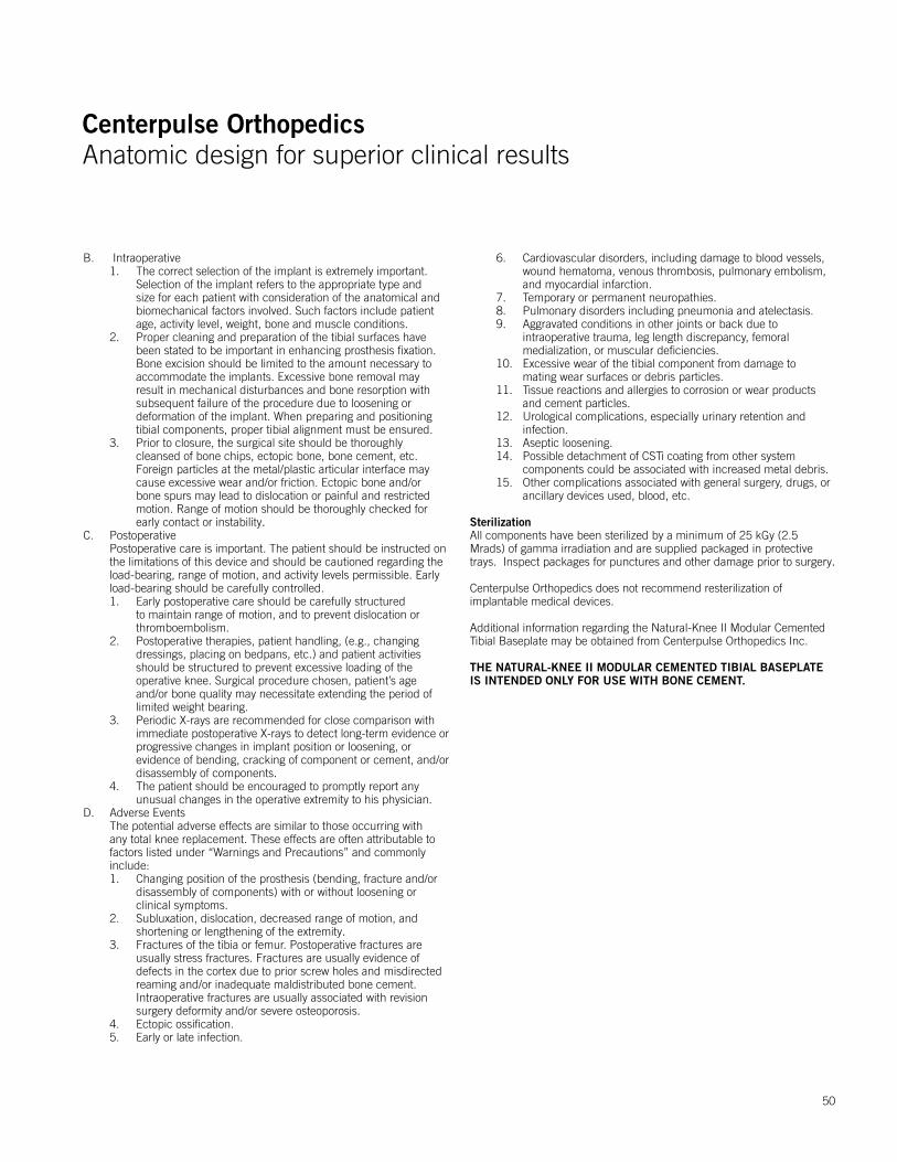
Centerpulse OrthopedicsAnatomic design for superior clinical results
Centerpulse OrthopedicsAnatomic design for superior clinical results
50
B. Intraoperative 1. The correct selection of the implant is extremely important. Selection of the implant refers to the appropriate type and size for each patient with consideration of the anatomical and biomechanical factors involved. Such factors include patient age, activity level, weight, bone and muscle conditions. 2. Proper cleaning and preparation of the tibial surfaces have been stated to be important in enhancing prosthesis fixation. Bone excision should be limited to the amount necessary to accommodate the implants. Excessive bone removal may result in mechanical disturbances and bone resorption with subsequent failure of the procedure due to loosening or deformation of the implant. When preparing and positioning tibial components, proper tibial alignment must be ensured. 3. Prior to closure, the surgical site should be thoroughly cleansed of bone chips, ectopic bone, bone cement, etc. Foreign particles at the metal/plastic articular interface may cause excessive wear and/or friction. Ectopic bone and/or bone spurs may lead to dislocation or painful and restricted motion. Range of motion should be thoroughly checked for early contact or instability.C. Postoperative Postoperative care is important. The patient should be instructed on
the limitations of this device and should be cautioned regarding the load-bearing, range of motion, and activity levels permissible. Early load-bearing should be carefully controlled.
1. Early postoperative care should be carefully structured to maintain range of motion, and to prevent dislocation or thromboembolism. 2. Postoperative therapies, patient handling, (e.g., changing dressings, placing on bedpans, etc.) and patient activities should be structured to prevent excessive loading of the operative knee. Surgical procedure chosen, patient’s age and/or bone quality may necessitate extending the period of limited weight bearing. 3. Periodic X-rays are recommended for close comparison with immediate postoperative X-rays to detect long-term evidence or progressive changes in implant position or loosening, or evidence of bending, cracking of component or cement, and/or disassembly of components. 4. The patient should be encouraged to promptly report any unusual changes in the operative extremity to his physician.D. Adverse Events The potential adverse effects are similar to those occurring with
any total knee replacement. These effects are often attributable to factors listed under “Warnings and Precautions” and commonly include:
1. Changing position of the prosthesis (bending, fracture and/or disassembly of components) with or without loosening or clinical symptoms. 2. Subluxation, dislocation, decreased range of motion, and shortening or lengthening of the extremity. 3. Fractures of the tibia or femur. Postoperative fractures are usually stress fractures. Fractures are usually evidence of defects in the cortex due to prior screw holes and misdirected reaming and/or inadequate maldistributed bone cement. Intraoperative fractures are usually associated with revision surgery deformity and/or severe osteoporosis. 4. Ectopic ossification. 5. Early or late infection.
6. Cardiovascular disorders, including damage to blood vessels, wound hematoma, venous thrombosis, pulmonary embolism, and myocardial infarction. 7. Temporary or permanent neuropathies. 8. Pulmonary disorders including pneumonia and atelectasis. 9. Aggravated conditions in other joints or back due to intraoperative trauma, leg length discrepancy, femoral medialization, or muscular deficiencies. 10. Excessive wear of the tibial component from damage to mating wear surfaces or debris particles. 11. Tissue reactions and allergies to corrosion or wear products and cement particles. 12. Urological complications, especially urinary retention and infection. 13. Aseptic loosening. 14. Possible detachment of CSTi coating from other system components could be associated with increased metal debris. 15. Other complications associated with general surgery, drugs, or ancillary devices used, blood, etc.
SterilizationAll components have been sterilized by a minimum of 25 kGy (2.5 Mrads) of gamma irradiation and are supplied packaged in protective trays. Inspect packages for punctures and other damage prior to surgery.
Centerpulse Orthopedics does not recommend resterilization of implantable medical devices.
Additional information regarding the Natural-Knee II Modular Cemented Tibial Baseplate may be obtained from Centerpulse Orthopedics Inc.
THE NATURAL-KNEE II MODULAR CEMENTED TIBIAL BASEPLATE IS INTENDED ONLY FOR USE WITH BONE CEMENT.
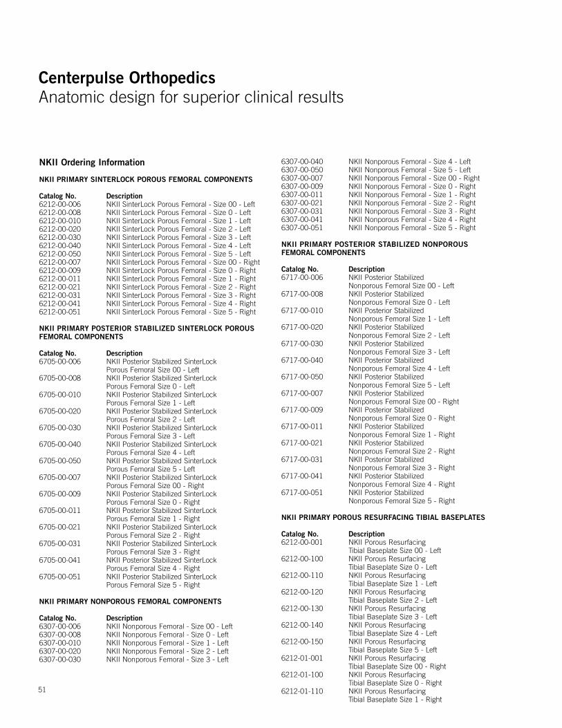
Centerpulse OrthopedicsAnatomic design for superior clinical results
Centerpulse OrthopedicsAnatomic design for superior clinical results
51
NKII Ordering Information NKII PRIMARY SINTERLOCK POROUS FEMORAL COMPONENTS
Catalog No. Description6212-00-006 NKII SinterLock Porous Femoral - Size 00 - Left6212-00-008 NKII SinterLock Porous Femoral - Size 0 - Left6212-00-010 NKII SinterLock Porous Femoral - Size 1 - Left6212-00-020 NKII SinterLock Porous Femoral - Size 2 - Left6212-00-030 NKII SinterLock Porous Femoral - Size 3 - Left6212-00-040 NKII SinterLock Porous Femoral - Size 4 - Left6212-00-050 NKII SinterLock Porous Femoral - Size 5 - Left6212-00-007 NKII SinterLock Porous Femoral - Size 00 - Right6212-00-009 NKII SinterLock Porous Femoral - Size 0 - Right6212-00-011 NKII SinterLock Porous Femoral - Size 1 - Right6212-00-021 NKII SinterLock Porous Femoral - Size 2 - Right6212-00-031 NKII SinterLock Porous Femoral - Size 3 - Right6212-00-041 NKII SinterLock Porous Femoral - Size 4 - Right6212-00-051 NKII SinterLock Porous Femoral - Size 5 - Right NKII PRIMARY POSTERIOR STABILIZED SINTERLOCK POROUSFEMORAL COMPONENTS
Catalog No. Description6705-00-006 NKII Posterior Stabilized SinterLock
Porous Femoral Size 00 - Left6705-00-008 NKII Posterior Stabilized SinterLock
Porous Femoral Size 0 - Left6705-00-010 NKII Posterior Stabilized SinterLock
Porous Femoral Size 1 - Left6705-00-020 NKII Posterior Stabilized SinterLock
Porous Femoral Size 2 - Left6705-00-030 NKII Posterior Stabilized SinterLock
Porous Femoral Size 3 - Left6705-00-040 NKII Posterior Stabilized SinterLock
Porous Femoral Size 4 - Left6705-00-050 NKII Posterior Stabilized SinterLock
Porous Femoral Size 5 - Left6705-00-007 NKII Posterior Stabilized SinterLock
Porous Femoral Size 00 - Right6705-00-009 NKII Posterior Stabilized SinterLock
Porous Femoral Size 0 - Right6705-00-011 NKII Posterior Stabilized SinterLock
Porous Femoral Size 1 - Right6705-00-021 NKII Posterior Stabilized SinterLock
Porous Femoral Size 2 - Right6705-00-031 NKII Posterior Stabilized SinterLock
Porous Femoral Size 3 - Right6705-00-041 NKII Posterior Stabilized SinterLock
Porous Femoral Size 4 - Right6705-00-051 NKII Posterior Stabilized SinterLock
Porous Femoral Size 5 - Right NKII PRIMARY NONPOROUS FEMORAL COMPONENTS
Catalog No. Description 6307-00-006 NKII Nonporous Femoral - Size 00 - Left6307-00-008 NKII Nonporous Femoral - Size 0 - Left6307-00-010 NKII Nonporous Femoral - Size 1 - Left6307-00-020 NKII Nonporous Femoral - Size 2 - Left6307-00-030 NKII Nonporous Femoral - Size 3 - Left
6307-00-040 NKII Nonporous Femoral - Size 4 - Left6307-00-050 NKII Nonporous Femoral - Size 5 - Left6307-00-007 NKII Nonporous Femoral - Size 00 - Right6307-00-009 NKII Nonporous Femoral - Size 0 - Right6307-00-011 NKII Nonporous Femoral - Size 1 - Right6307-00-021 NKII Nonporous Femoral - Size 2 - Right6307-00-031 NKII Nonporous Femoral - Size 3 - Right6307-00-041 NKII Nonporous Femoral - Size 4 - Right6307-00-051 NKII Nonporous Femoral - Size 5 - Right
NKII PRIMARY POSTERIOR STABILIZED NONPOROUSFEMORAL COMPONENTS
Catalog No. Description6717-00-006 NKII Posterior Stabilized
Nonporous Femoral Size 00 - Left6717-00-008 NKII Posterior Stabilized
Nonporous Femoral Size 0 - Left6717-00-010 NKII Posterior Stabilized
Nonporous Femoral Size 1 - Left6717-00-020 NKII Posterior Stabilized
Nonporous Femoral Size 2 - Left6717-00-030 NKII Posterior Stabilized
Nonporous Femoral Size 3 - Left6717-00-040 NKII Posterior Stabilized
Nonporous Femoral Size 4 - Left6717-00-050 NKII Posterior Stabilized
Nonporous Femoral Size 5 - Left6717-00-007 NKII Posterior Stabilized
Nonporous Femoral Size 00 - Right6717-00-009 NKII Posterior Stabilized
Nonporous Femoral Size 0 - Right6717-00-011 NKII Posterior Stabilized
Nonporous Femoral Size 1 - Right6717-00-021 NKII Posterior Stabilized
Nonporous Femoral Size 2 - Right6717-00-031 NKII Posterior Stabilized
Nonporous Femoral Size 3 - Right6717-00-041 NKII Posterior Stabilized
Nonporous Femoral Size 4 - Right6717-00-051 NKII Posterior Stabilized
Nonporous Femoral Size 5 - Right NKII PRIMARY POROUS RESURFACING TIBIAL BASEPLATES
Catalog No. Description 6212-00-001 NKII Porous Resurfacing
Tibial Baseplate Size 00 - Left6212-00-100 NKII Porous Resurfacing
Tibial Baseplate Size 0 - Left6212-00-110 NKII Porous Resurfacing
Tibial Baseplate Size 1 - Left6212-00-120 NKII Porous Resurfacing
Tibial Baseplate Size 2 - Left6212-00-130 NKII Porous Resurfacing
Tibial Baseplate Size 3 - Left6212-00-140 NKII Porous Resurfacing
Tibial Baseplate Size 4 - Left6212-00-150 NKII Porous Resurfacing
Tibial Baseplate Size 5 - Left6212-01-001 NKII Porous Resurfacing
Tibial Baseplate Size 00 - Right6212-01-100 NKII Porous Resurfacing
Tibial Baseplate Size 0 - Right6212-01-110 NKII Porous Resurfacing
Tibial Baseplate Size 1 - Right
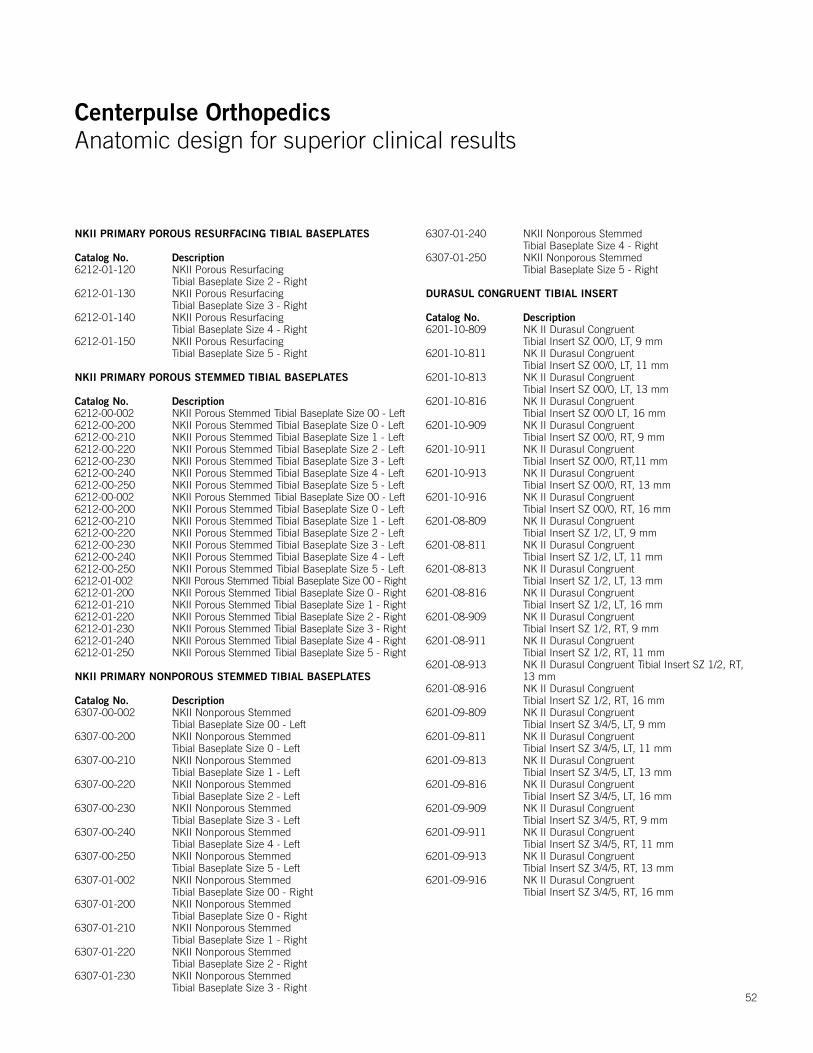
Centerpulse OrthopedicsAnatomic design for superior clinical results
Centerpulse OrthopedicsAnatomic design for superior clinical results
52
NKII PRIMARY POROUS RESURFACING TIBIAL BASEPLATES
Catalog No. Description6212-01-120 NKII Porous Resurfacing
Tibial Baseplate Size 2 - Right6212-01-130 NKII Porous Resurfacing
Tibial Baseplate Size 3 - Right6212-01-140 NKII Porous Resurfacing
Tibial Baseplate Size 4 - Right6212-01-150 NKII Porous Resurfacing
Tibial Baseplate Size 5 - Right
NKII PRIMARY POROUS STEMMED TIBIAL BASEPLATES
Catalog No. Description 6212-00-002 NKII Porous Stemmed Tibial Baseplate Size 00 - Left6212-00-200 NKII Porous Stemmed Tibial Baseplate Size 0 - Left6212-00-210 NKII Porous Stemmed Tibial Baseplate Size 1 - Left6212-00-220 NKII Porous Stemmed Tibial Baseplate Size 2 - Left6212-00-230 NKII Porous Stemmed Tibial Baseplate Size 3 - Left6212-00-240 NKII Porous Stemmed Tibial Baseplate Size 4 - Left6212-00-250 NKII Porous Stemmed Tibial Baseplate Size 5 - Left6212-00-002 NKII Porous Stemmed Tibial Baseplate Size 00 - Left6212-00-200 NKII Porous Stemmed Tibial Baseplate Size 0 - Left6212-00-210 NKII Porous Stemmed Tibial Baseplate Size 1 - Left6212-00-220 NKII Porous Stemmed Tibial Baseplate Size 2 - Left6212-00-230 NKII Porous Stemmed Tibial Baseplate Size 3 - Left6212-00-240 NKII Porous Stemmed Tibial Baseplate Size 4 - Left6212-00-250 NKII Porous Stemmed Tibial Baseplate Size 5 - Left6212-01-002 NKII Porous Stemmed Tibial Baseplate Size 00 - Right6212-01-200 NKII Porous Stemmed Tibial Baseplate Size 0 - Right6212-01-210 NKII Porous Stemmed Tibial Baseplate Size 1 - Right6212-01-220 NKII Porous Stemmed Tibial Baseplate Size 2 - Right6212-01-230 NKII Porous Stemmed Tibial Baseplate Size 3 - Right6212-01-240 NKII Porous Stemmed Tibial Baseplate Size 4 - Right6212-01-250 NKII Porous Stemmed Tibial Baseplate Size 5 - Right NKII PRIMARY NONPOROUS STEMMED TIBIAL BASEPLATES
Catalog No. Description6307-00-002 NKII Nonporous Stemmed
Tibial Baseplate Size 00 - Left6307-00-200 NKII Nonporous Stemmed
Tibial Baseplate Size 0 - Left6307-00-210 NKII Nonporous Stemmed
Tibial Baseplate Size 1 - Left6307-00-220 NKII Nonporous Stemmed
Tibial Baseplate Size 2 - Left6307-00-230 NKII Nonporous Stemmed
Tibial Baseplate Size 3 - Left6307-00-240 NKII Nonporous Stemmed
Tibial Baseplate Size 4 - Left6307-00-250 NKII Nonporous Stemmed
Tibial Baseplate Size 5 - Left6307-01-002 NKII Nonporous Stemmed
Tibial Baseplate Size 00 - Right6307-01-200 NKII Nonporous Stemmed
Tibial Baseplate Size 0 - Right6307-01-210 NKII Nonporous Stemmed
Tibial Baseplate Size 1 - Right6307-01-220 NKII Nonporous Stemmed
Tibial Baseplate Size 2 - Right6307-01-230 NKII Nonporous Stemmed
Tibial Baseplate Size 3 - Right
6307-01-240 NKII Nonporous Stemmed Tibial Baseplate Size 4 - Right
6307-01-250 NKII Nonporous Stemmed Tibial Baseplate Size 5 - Right
DURASUL CONGRUENT TIBIAL INSERT
Catalog No. Description6201-10-809 NK II Durasul Congruent
Tibial Insert SZ 00/0, LT, 9 mm6201-10-811 NK II Durasul Congruent
Tibial Insert SZ 00/0, LT, 11 mm6201-10-813 NK II Durasul Congruent
Tibial Insert SZ 00/0, LT, 13 mm6201-10-816 NK II Durasul Congruent
Tibial Insert SZ 00/0 LT, 16 mm6201-10-909 NK II Durasul Congruent
Tibial Insert SZ 00/0, RT, 9 mm6201-10-911 NK II Durasul Congruent
Tibial Insert SZ 00/0, RT,11 mm6201-10-913 NK II Durasul Congruent
Tibial Insert SZ 00/0, RT, 13 mm6201-10-916 NK II Durasul Congruent
Tibial Insert SZ 00/0, RT, 16 mm6201-08-809 NK II Durasul Congruent
Tibial Insert SZ 1/2, LT, 9 mm6201-08-811 NK II Durasul Congruent
Tibial Insert SZ 1/2, LT, 11 mm6201-08-813 NK II Durasul Congruent
Tibial Insert SZ 1/2, LT, 13 mm6201-08-816 NK II Durasul Congruent
Tibial Insert SZ 1/2, LT, 16 mm6201-08-909 NK II Durasul Congruent
Tibial Insert SZ 1/2, RT, 9 mm6201-08-911 NK II Durasul Congruent
Tibial Insert SZ 1/2, RT, 11 mm6201-08-913 NK II Durasul Congruent Tibial Insert SZ 1/2, RT,
13 mm6201-08-916 NK II Durasul Congruent
Tibial Insert SZ 1/2, RT, 16 mm6201-09-809 NK II Durasul Congruent
Tibial Insert SZ 3/4/5, LT, 9 mm6201-09-811 NK II Durasul Congruent
Tibial Insert SZ 3/4/5, LT, 11 mm6201-09-813 NK II Durasul Congruent
Tibial Insert SZ 3/4/5, LT, 13 mm6201-09-816 NK II Durasul Congruent
Tibial Insert SZ 3/4/5, LT, 16 mm6201-09-909 NK II Durasul Congruent
Tibial Insert SZ 3/4/5, RT, 9 mm6201-09-911 NK II Durasul Congruent
Tibial Insert SZ 3/4/5, RT, 11 mm6201-09-913 NK II Durasul Congruent
Tibial Insert SZ 3/4/5, RT, 13 mm6201-09-916 NK II Durasul Congruent
Tibial Insert SZ 3/4/5, RT, 16 mm
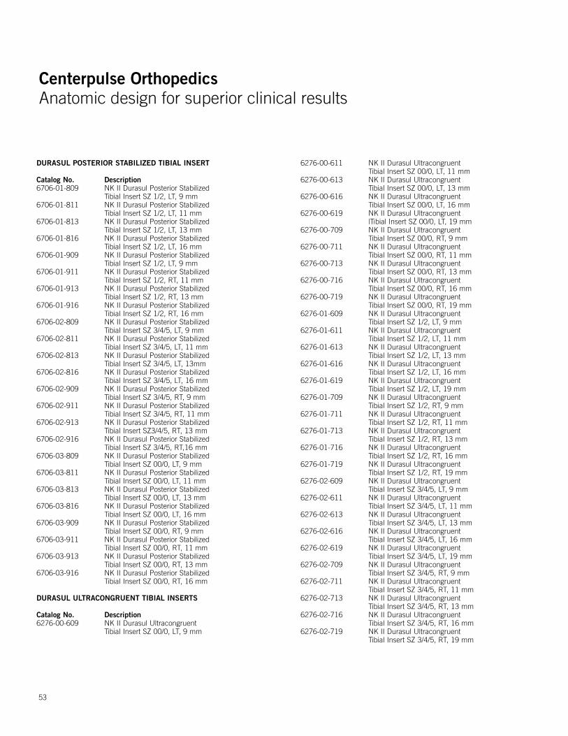
Centerpulse OrthopedicsAnatomic design for superior clinical results
Centerpulse OrthopedicsAnatomic design for superior clinical results
53
DURASUL POSTERIOR STABILIZED TIBIAL INSERT
Catalog No. Description6706-01-809 NK II Durasul Posterior Stabilized
Tibial Insert SZ 1/2, LT, 9 mm6706-01-811 NK II Durasul Posterior Stabilized
Tibial Insert SZ 1/2, LT, 11 mm6706-01-813 NK II Durasul Posterior Stabilized
Tibial Insert SZ 1/2, LT, 13 mm6706-01-816 NK II Durasul Posterior Stabilized
Tibial Insert SZ 1/2, LT, 16 mm6706-01-909 NK II Durasul Posterior Stabilized
Tibial Insert SZ 1/2, LT, 9 mm6706-01-911 NK II Durasul Posterior Stabilized
Tibial Insert SZ 1/2, RT, 11 mm6706-01-913 NK II Durasul Posterior Stabilized
Tibial Insert SZ 1/2, RT, 13 mm6706-01-916 NK II Durasul Posterior Stabilized
Tibial Insert SZ 1/2, RT, 16 mm6706-02-809 NK II Durasul Posterior Stabilized
Tibial Insert SZ 3/4/5, LT, 9 mm6706-02-811 NK II Durasul Posterior Stabilized
Tibial Insert SZ 3/4/5, LT, 11 mm6706-02-813 NK II Durasul Posterior Stabilized
Tibial Insert SZ 3/4/5, LT, 13mm6706-02-816 NK II Durasul Posterior Stabilized
Tibial Insert SZ 3/4/5, LT, 16 mm6706-02-909 NK II Durasul Posterior Stabilized
Tibial Insert SZ 3/4/5, RT, 9 mm6706-02-911 NK II Durasul Posterior Stabilized
Tibial Insert SZ 3/4/5, RT, 11 mm6706-02-913 NK II Durasul Posterior Stabilized
Tibial Insert SZ3/4/5, RT, 13 mm6706-02-916 NK II Durasul Posterior Stabilized
Tibial Insert SZ 3/4/5, RT,16 mm6706-03-809 NK II Durasul Posterior Stabilized
Tibial Insert SZ 00/0, LT, 9 mm6706-03-811 NK II Durasul Posterior Stabilized
Tibial Insert SZ 00/0, LT, 11 mm6706-03-813 NK II Durasul Posterior Stabilized
Tibial Insert SZ 00/0, LT, 13 mm6706-03-816 NK II Durasul Posterior Stabilized
Tibial Insert SZ 00/0, LT, 16 mm6706-03-909 NK II Durasul Posterior Stabilized
Tibial Insert SZ 00/0, RT, 9 mm6706-03-911 NK II Durasul Posterior Stabilized
Tibial Insert SZ 00/0, RT, 11 mm6706-03-913 NK II Durasul Posterior Stabilized
Tibial Insert SZ 00/0, RT, 13 mm6706-03-916 NK II Durasul Posterior Stabilized
Tibial Insert SZ 00/0, RT, 16 mm
DURASUL ULTRACONGRUENT TIBIAL INSERTS
Catalog No. Description6276-00-609 NK II Durasul Ultracongruent
Tibial Insert SZ 00/0, LT, 9 mm
6276-00-611 NK II Durasul Ultracongruent Tibial Insert SZ 00/0, LT, 11 mm
6276-00-613 NK II Durasul Ultracongruent Tibial Insert SZ 00/0, LT, 13 mm
6276-00-616 NK II Durasul Ultracongruent Tibial Insert SZ 00/0, LT, 16 mm
6276-00-619 NK II Durasul Ultracongruent |Tibial Insert SZ 00/0, LT, 19 mm
6276-00-709 NK II Durasul Ultracongruent Tibial Insert SZ 00/0, RT, 9 mm
6276-00-711 NK II Durasul Ultracongruent Tibial Insert SZ 00/0, RT, 11 mm
6276-00-713 NK II Durasul Ultracongruent Tibial Insert SZ 00/0, RT, 13 mm
6276-00-716 NK II Durasul Ultracongruent Tibial Insert SZ 00/0, RT, 16 mm
6276-00-719 NK II Durasul Ultracongruent Tibial Insert SZ 00/0, RT, 19 mm
6276-01-609 NK II Durasul Ultracongruent Tibial Insert SZ 1/2, LT, 9 mm
6276-01-611 NK II Durasul Ultracongruent Tibial Insert SZ 1/2, LT, 11 mm
6276-01-613 NK II Durasul Ultracongruent Tibial Insert SZ 1/2, LT, 13 mm
6276-01-616 NK II Durasul Ultracongruent Tibial Insert SZ 1/2, LT, 16 mm
6276-01-619 NK II Durasul Ultracongruent Tibial Insert SZ 1/2, LT, 19 mm
6276-01-709 NK II Durasul Ultracongruent Tibial Insert SZ 1/2, RT, 9 mm
6276-01-711 NK II Durasul Ultracongruent Tibial Insert SZ 1/2, RT, 11 mm
6276-01-713 NK II Durasul Ultracongruent Tibial Insert SZ 1/2, RT, 13 mm
6276-01-716 NK II Durasul Ultracongruent Tibial Insert SZ 1/2, RT, 16 mm
6276-01-719 NK II Durasul Ultracongruent Tibial Insert SZ 1/2, RT, 19 mm
6276-02-609 NK II Durasul Ultracongruent Tibial Insert SZ 3/4/5, LT, 9 mm
6276-02-611 NK II Durasul Ultracongruent Tibial Insert SZ 3/4/5, LT, 11 mm
6276-02-613 NK II Durasul Ultracongruent Tibial Insert SZ 3/4/5, LT, 13 mm
6276-02-616 NK II Durasul Ultracongruent Tibial Insert SZ 3/4/5, LT, 16 mm
6276-02-619 NK II Durasul Ultracongruent Tibial Insert SZ 3/4/5, LT, 19 mm
6276-02-709 NK II Durasul Ultracongruent Tibial Insert SZ 3/4/5, RT, 9 mm
6276-02-711 NK II Durasul Ultracongruent Tibial Insert SZ 3/4/5, RT, 11 mm
6276-02-713 NK II Durasul Ultracongruent Tibial Insert SZ 3/4/5, RT, 13 mm
6276-02-716 NK II Durasul Ultracongruent Tibial Insert SZ 3/4/5, RT, 16 mm
6276-02-719 NK II Durasul Ultracongruent Tibial Insert SZ 3/4/5, RT, 19 mm
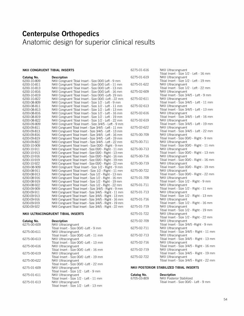
Centerpulse OrthopedicsAnatomic design for superior clinical results
Centerpulse OrthopedicsAnatomic design for superior clinical results
54
NKII CONGRUENT TIBIAL INSERTS
Catalog No. Description6200-10-809 NKII Congruent Tibial Insert - Size 00/0 Left - 9 mm6200-10-811 NKII Congruent Tibial Insert - Size 00/0 Left - 11 mm6200-10-813 NKII Congruent Tibial Insert - Size 00/0 Left - 13 mm6200-10-816 NKII Congruent Tibial Insert - Size 00/0 Left - 16 mm6200-10-819 NKII Congruent Tibial Insert - Size 00/0 -Left- 19 mm6200-10-822 NKII Congruent Tibial Insert - Size 00/0 -Left - 22 mm6200-08-809 NKII Congruent Tibial Insert - Size 1/2 - Left - 9 mm6200-08-811 NKII Congruent Tibial Insert - Size 1/2 - Left - 11 mm6200-08-813 NKII Congruent Tibial Insert - Size 1/2 - Left - 13 mm6200-08-816 NKII Congruent Tibial Insert - Size 1/2 - Left - 16 mm6200-08-819 NKII Congruent Tibial Insert - Size 1/2 - Left - 19 mm6200-08-822 NKII Congruent Tibial Insert - Size 1/2 - Left - 22 mm6200-09-809 NKII Congruent Tibial Insert - Size 3/4/5 - Left - 9 mm6200-09-811 NKII Congruent Tibial Insert - Size 3/4/5 - Left - 11 mm6200-09-813 NKII Congruent Tibial Insert - Size 3/4/5 - Left - 13 mm6200-09-816 NKII Congruent Tibial Insert - Size 3/4/5 - Left - 16 mm6200-09-819 NKII Congruent Tibial Insert - Size 3/4/5 - Left - 19 mm 6200-09-822 NKII Congruent Tibial Insert - Size 3/4/5 - Left - 22 mm6200-10-909 NKII Congruent Tibial Insert - Size 00/0 - Right - 9 mm6200-10-911 NKII Congruent Tibial Insert - Size 00/0 - Right - 11 mm6200-10-913 NKII Congruent Tibial Insert - Size 00/0 - Right - 13 mm 6200-10-916 NKII Congruent Tibial Insert - Size 00/0 - Right - 16 mm 6200-10-919 NKII Congruent Tibial Insert - Size 00/0 - Right - 19 mm6200-10-922 NKII Congruent Tibial Insert - Size 00/0 - Right - 22 mm6200-08-909 NKII Congruent Tibial Insert - Size 1/2 - Right - 9 mm 6200-08-911 NKII Congruent Tibial Insert - Size 1/2 - Right - 11 mm 6200-08-913 NKII Congruent Tibial Insert - Size 1/2 - Right - 13 mm6200-08-916 NKII Congruent Tibial Insert - Size 1/2 - Right - 16 mm6200-08-919 NKII Congruent Tibial Insert - Size 1/2 - Right - 19 mm6200-08-922 NKII Congruent Tibial Insert - Size 1/2 - Right - 22 mm6200-09-909 NKII Congruent Tibial Insert - Size 3/4/5 - Right - 9 mm6200-09-911 NKII Congruent Tibial Insert - Size 3/4/5 - Right - 11 mm 6200-09-913 NKII Congruent Tibial Insert - Size 3/4/5 - Right - 13 mm 6200-09-916 NKII Congruent Tibial Insert - Size 3/4/5 - Right - 16 mm6200-09-919 NKII Congruent Tibial Insert - Size 3/4/5 - Right - 19 mm 6200-09-922 NKII Congruent Tibial Insert - Size 3/4/5 - Right - 22 mm
NKII ULTRACONGRUENT TIBIAL INSERTS
Catalog No. Description6275-00-609 NKII Ultracongruent
Tibial Insert - Size 00/0 -Left - 9 mm6275-00-611 NKII Ultracongruent
Tibial Insert - Size 00/0 -Left - 11 mm6275-00-613 NKII Ultracongruent
Tibial Insert - Size 00/0 -Left - 13 mm6275-00-616 NKII Ultracongruent
Tibial Insert - Size 00/0 -Left - 16 mm6275-00-619 NKII Ultracongruent
Tibial Insert - Size 00/0 -Left - 19 mm6275-00-622 NKII Ultracongruent
Tibial Insert - Size 00/0 -Left - 22 mm6275-01-609 NKII Ultracongruent
Tibial Insert - Size 1/2 - Left - 9 mm6275-01-611 NKII Ultracongruent
Tibial Insert - Size 1/2 - Left - 11 mm6275-01-613 NKII Ultracongruent
Tibial Insert - Size 1/2 - Left - 13 mm
6275-01-616 NKII Ultracongruent Tibial Insert - Size 1/2 - Left - 16 mm
6275-01-619 NKII Ultracongruent Tibial Insert - Size 1/2 - Left - 19 mm
6275-01-622 NKII Ultracongruent Tibial Insert - Size 1/2 - Left - 22 mm
6275-02-609 NKII Ultracongruent Tibial Insert - Size 3/4/5 - Left - 9 mm
6275-02-611 NKII Ultracongruent Tibial Insert - Size 3/4/5 - Left - 11 mm
6275-02-613 NKII Ultracongruent Tibial Insert - Size 3/4/5 - Left - 13 mm
6275-02-616 NKII Ultracongruent Tibial Insert - Size 3/4/5 - Left - 16 mm
6275-02-619 NKII Ultracongruent Tibial Insert - Size 3/4/5 - Left - 19 mm
6275-02-622 NKII Ultracongruent Tibial Insert - Size 3/4/5 - Left - 22 mm
6275-00-709 NKII Ultracongruent Tibial Insert - Size 00/0 - Right - 9 mm
6275-00-711 NKII Ultracongruent Tibial Insert - Size 00/0 - Right - 11 mm
6275-00-713 NKII Ultracongruent Tibial Insert - Size 00/0 - Right - 13 mm
6275-00-716 NKII Ultracongruent Tibial Insert - Size 00/0 - Right - 16 mm
6275-00-719 NKII Ultracongruent Tibial Insert - Size 00/0 - Right - 19 mm
6275-00-722 NKII Ultracongruent Tibial Insert - Size 00/0 - Right - 22 mm
6275-01-709 NKII Ultracongruent Tibial Insert - Size 1/2 - Right - 9 mm
6275-01-711 NKII Ultracongruent Tibial Insert - Size 1/2 - Right - 11 mm
6275-01-713 NKII Ultracongruent Tibial Insert - Size 1/2 - Right - 13 mm
6275-01-716 NKII Ultracongruent Tibial Insert - Size 1/2 - Right - 16 mm
6275-01-719 NKII Ultracongruent Tibial Insert - Size 1/2 - Right - 19 mm
6275-01-722 NKII Ultracongruent Tibial Insert - Size 1/2 - Right - 22 mm
6275-02-709 NKII Ultracongruent Tibial Insert - Size 3/4/5 -Right - 9 mm
6275-02-711 NKII Ultracongruent Tibial Insert - Size 3/4/5 - Right - 11 mm
6275-02-713 NKII Ultracongruent Tibial Insert - Size 3/4/5 - Right - 13 mm
6275-02-716 NKII Ultracongruent Tibial Insert - Size 3/4/5 - Right - 16 mm
6275-02-719 NKII Ultracongruent Tibial Insert - Size 3/4/5 - Right - 19 mm
6275-02-722 NKII Ultracongruent Tibial Insert - Size 3/4/5 - Right - 22 mm
NKII POSTERIOR STABILIZED TIBIAL INSERTS
Catalog No. Description6705-03-809 NKII Posterior Stabilized
Tibial Insert - Size 00/0 - Left - 9 mm
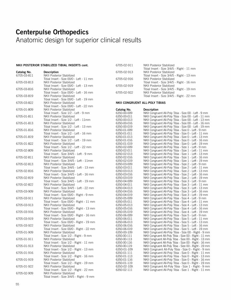
Centerpulse OrthopedicsAnatomic design for superior clinical results
Centerpulse OrthopedicsAnatomic design for superior clinical results
55
NKII POSTERIOR STABILIZED TIBIAL INSERTS cont.
Catalog No. Description6705-03-811 NKII Posterior Stabilized
Tibial Insert - Size 00/0 - Left - 11 mm6705-03-813 NKII Posterior Stabilized
Tibial Insert - Size 00/0 - Left - 13 mm 6705-03-816 NKII Posterior Stabilized
Tibial Insert - Size 00/0 - Left - 16 mm6705-03-819 NKII Posterior Stabilized
Tibial Insert - Size 00/0 - Left - 19 mm 6705-03-822 NKII Posterior Stabilized
Tibial Insert - Size 00/0 - Left - 22 mm6705-01-809 NKII Posterior Stabilized
Tibial Insert - Size 1/2 - Left - 9 mm6705-01-811 NKII Posterior Stabilized
Tibial Insert - Size 1/2 - Left - 11mm6705-01-813 NKII Posterior Stabilized
Tibial Insert - Size 1/2 - Left - 13 mm 6705-01-816 NKII Posterior Stabilized
Tibial Insert - Size 1/2 - Left - 16 mm 6705-01-819 NKII Posterior Stabilized
Tibial Insert - Size 1/2 - Left - 19 mm6705-01-822 NKII Posterior Stabilized
Tibial Insert - Size 1/2 - Left - 22 mm6705-02-809 NKII Posterior Stabilized
Tibial Insert - Size 3/4/5 - Left - 9 mm6705-02-811 NKII Posterior Stabilized
Tibial Insert - Size 3/4/5 - Left - 11mm6705-02-813 NKII Posterior Stabilized
Tibial Insert - Size 3/4/5 - Left - 13 mm 6705-02-816 NKII Posterior Stabilized
Tibial Insert - Size 3/4/5 - Left - 16 mm 6705-02-819 NKII Posterior Stabilized
Tibial Insert - Size 3/4/5 - Left - 19 mm 6705-02-822 NKII Posterior Stabilized
Tibial Insert - Size 3/4/5 - Left - 22 mm6705-03-909 NKII Posterior Stabilized
Tibial Insert - Size 00/0 - Right - 9 mm6705-03-911 NKII Posterior Stabilized
Tibial Insert - Size 00/0 - Right - 11 mm6705-03-913 NKII Posterior Stabilized
Tibial Insert - Size 00/0 - Right - 13 mm6705-03-916 NKII Posterior Stabilized
Tibial Insert - Size 00/0 - Right - 16 mm6705-03-919 NKII Posterior Stabilized
Tibial Insert - Size 00/0 - Right - 19 mm6705-03-922 NKII Posterior Stabilized
Tibial Insert - Size 00/0 - Right - 22 mm 6705-01-909 NKII Posterior Stabilized
Tibial Insert - Size 1/2 - Right - 9 mm6705-01-911 NKII Posterior Stabilized
Tibial Insert - Size 1/2 - Right - 11 mm6705-01-913 NKII Posterior Stabilized
Tibial Insert - Size 1/2 - Right - 13 mm6705-01-916 NKII Posterior Stabilized
Tibial Insert - Size 1/2 - Right - 16 mm6705-01-919 NKII Posterior Stabilized
Tibial Insert - Size 1/2 - Right - 19 mm6705-01-922 NKII Posterior Stabilized
Tibial Insert - Size 1/2 - Right - 22 mm6705-02-909 NKII Posterior Stabilized
Tibial Insert - Size 3/4/5 - Right - 9 mm
6705-02-911 NKII Posterior Stabilized Tibial Insert - Size 3/4/5 - Right - 11 mm
6705-02-913 NKII Posterior Stabilized Tibial Insert - Size 3/4/5 - Right - 13 mm
6705-02-916 NKII Posterior Stabilized Tibial Insert - Size 3/4/5 - Right - 16 mm
6705-02-919 NKII Posterior Stabilized Tibial Insert - Size 3/4/5 - Right - 19 mm
6705-02-922 NKII Posterior Stabilized Tibial Insert - Size 3/4/5 - Right - 22 mm
NKII CONGRUENT ALL-POLY TIBIAS
Catalog No. Description6350-00-009 NKII Congruent All-Poly Tibia - Size 00 - Left - 9 mm6350-00-011 NKII Congruent All-Poly Tibia - Size 00 - Left - 11 mm6350-00-013 NKII Congruent All-Poly Tibia - Size 00 - Left - 13 mm6350-00-016 NKII Congruent All-Poly Tibia - Size 00 - Left - 16 mm6350-00-019 NKII Congruent All-Poly Tibia - Size 00 - Left - 19 mm6350-01-009 NKII Congruent All-Poly Tibia - Size 0 - Left - 9 mm 6350-01-011 NKII Congruent All-Poly Tibia - Size 0 - Left - 11 mm6350-01-013 NKII Congruent All-Poly Tibia - Size 0 - Left - 13 mm6350-01-016 NKII Congruent All-Poly Tibia - Size 0 - Left - 16 mm6350-01-019 NKII Congruent All-Poly Tibia - Size 0 - Left - 19 mm6350-02-009 NKII Congruent All-Poly Tibia - Size 1 - Left - 9 mm6350-02-011 NKII Congruent All-Poly Tibia - Size 1 - Left - 11 mm6350-02-013 NKII Congruent All-Poly Tibia - Size 1 - Left - 13 mm6350-02-016 NKII Congruent All-Poly Tibia - Size 1 - Left - 16 mm6350-02-019 NKII Congruent All-Poly Tibia - Size 1 - Left - 19 mm6350-03-009 NKII Congruent All-Poly Tibia - Size 2 - Left - 9 mm6350-03-011 NKII Congruent All-Poly Tibia - Size 2 - Left - 11 mm6350-03-013 NKII Congruent All-Poly Tibia - Size 2 - Left - 13 mm6350-03-016 NKII Congruent All-Poly Tibia - Size 2 - Left - 16 mm6350-03-019 NKII Congruent All-Poly Tibia - Size 2 - Left - 19 mm6350-04-009 NKII Congruent All-Poly Tibia - Size 3 - Left - 9 mm 6350-04-011 NKII Congruent All-Poly Tibia - Size 3 - Left - 11 mm6350-04-013 NKII Congruent All-Poly Tibia - Size 3 - Left - 13 mm6350-04-016 NKII Congruent All-Poly Tibia - Size 3 - Left - 16 mm6350-04-019 NKII Congruent All-Poly Tibia - Size 3 - Left - 19 mm6350-05-009 NKII Congruent All-Poly Tibia - Size 4 - Left - 9 mm6350-05-011 NKII Congruent All-Poly Tibia - Size 4 - Left - 11 mm6350-05-013 NKII Congruent All-Poly Tibia - Size 4 - Left - 13 mm6350-05-016 NKII Congruent All-Poly Tibia - Size 4 - Left - 16 mm6350-05-019 NKII Congruent All-Poly Tibia - Size 4 - Left - 19 mm6350-06-009 NKII Congruent All-Poly Tibia - Size 5 - Left - 9 mm 6350-06-011 NKII Congruent All-Poly Tibia - Size 5 - Left - 11 mm6350-06-013 NKII Congruent All-Poly Tibia - Size 5 - Left - 13 mm 6350-06-016 NKII Congruent All-Poly Tibia - Size 5 - Left - 16 mm6350-06-019 NKII Congruent All-Poly Tibia - Size 5 - Left - 19 mm6350-00-109 NKII Congruent All-Poly Tibia - Size 00 - Right - 9 mm 6350-00-111 NKII Congruent All-Poly Tibia - Size 00 - Right - 11 mm6350-00-113 NKII Congruent All-Poly Tibia - Size 00 - Right - 13 mm 6350-00-116 NKII Congruent All-Poly Tibia - Size 00 - Right - 16 mm6350-00-119 NKII Congruent All-Poly Tibia - Size 00 - Right - 19 mm6350-01-109 NKII Congruent All-Poly Tibia - Size 0 - Right - 9 mm 6350-01-111 NKII Congruent All-Poly Tibia - Size 0 - Right - 11 mm6350-01-113 NKII Congruent All-Poly Tibia - Size 0 - Right - 13 mm6350-01-116 NKII Congruent All-Poly Tibia - Size 0 - Right - 16 mm6350-01-119 NKII Congruent All-Poly Tibia - Size 0 - Right - 19 mm6350-02-109 NKII Congruent All-Poly Tibia - Size 1 - Right - 9 mm6350-02-111 NKII Congruent All-Poly Tibia - Size 1 - Right - 11 mm

Centerpulse OrthopedicsAnatomic design for superior clinical results
Centerpulse OrthopedicsAnatomic design for superior clinical results
56
NKII CONGRUENT ALL-POLY TIBIAS cont.
Catalog No. Description6350-02-113 NKII Congruent All-Poly Tibia - Size 1 - Right - 13 mm6350-02-116 NKII Congruent All-Poly Tibia - Size 1 - Right - 16 mm6350-02-119 NKII Congruent All-Poly Tibia - Size 1 - Right - 19 mm6350-03-109 NKII Congruent All-Poly Tibia - Size 2 - Right - 9 mm6350-03-111 NKII Congruent All-Poly Tibia - Size 2 - Right - 11 mm6350-03-113 NKII Congruent All-Poly Tibia - Size 2 - Right - 13 mm6350-03-116 NKII Congruent All-Poly Tibia - Size 2 - Right - 16 mm6350-03-119 NKII Congruent All-Poly Tibia - Size 2 - Right - 19 mm 6350-04-109 NKII Congruent All-Poly Tibia - Size 3 - Right - 9 mm 6350-04-111 NKII Congruent All-Poly Tibia - Size 3 - Right - 11 mm6350-04-113 NKII Congruent All-Poly Tibia - Size 3 - Right - 13 mm6350-04-116 NKII Congruent All-Poly Tibia - Size 3 - Right - 16 mm6350-04-119 NKII Congruent All-Poly Tibia - Size 3 - Right - 19 mm6350-05-109 NKII Congruent All-Poly Tibia - Size 4 - Right - 9 mm6350-05-111 NKII Congruent All-Poly Tibia - Size 4 - Right - 11 mm6350-05-113 NKII Congruent All-Poly Tibia - Size 4 - Right - 13 mm6350-05-116 NKII Congruent All-Poly Tibia - Size 4 - Right - 16 mm6350-05-119 NKII Congruent All-Poly Tibia - Size 4 - Right - 19 mm6350-06-109 NKII Congruent All-Poly Tibia - Size 5 - Right - 9 mm6350-06-111 NKII Congruent All-Poly Tibia - Size 5 - Right - 11 mm 6350-06-113 NKII Congruent All-Poly Tibia - Size 5 - Right - 13 mm6350-06-116 NKII Congruent All-Poly Tibia - Size 5 - Right - 16 mm6350-06-119 NKII Congruent All-Poly Tibia - Size 5 - Right - 19 mm NK II ULTRACONGRUENT ALL-POLY TIBIAS
Catalog No. Description6218-00-809 NKII Ultracongruent All-Poly
Tibia - Size 00 - Left - 9 mm6218-00-811 NKII Ultracongruent All-Poly
Tibia - Size 00 - Left - 11 mm6218-00-813 NKII Ultracongruent All-Poly
Tibia - Size 00 - Left - 3 mm6218-00-816 NKII Ultracongruent All-Poly
Tibia - Size 00 - Left - 6 mm6218-00-819 NKII Ultracongruent All-Poly
Tibia - Size 00 - Left - 9 mm6218-01-809 NKII Ultracongruent All-Poly Tibia - Size 0 - Left - 9 mm6218-01-811 NKII Ultracongruent All-Poly
Tibia - Size 0 - Left - 11 mm6218-01-813 NKII Ultracongruent All-Poly
Tibia - Size 0 - Left - 13 mm6218-01-816 NKII Ultracongruent All-Poly
Tibia - Size 0 - Left - 16 mm 6218-01-819 NKII Ultracongruent All-Poly
Tibia - Size 0 - Left - 19 mm 6218-10-809 NKII Ultracongruent All-Poly
Tibia - Size 1 - Left - 9 mm 6218-10-811 NKII Ultracongruent All-Poly
Tibia - Size 1 - Left - 11 mm 6218-10-813 NKII Ultracongruent All-Poly
Tibia - Size 1 - Left - 13 mm6218-10-816 NKII Ultracongruent All-Poly
Tibia - Size 1 - Left - 16 mm 6218-10-819 NKII Ultracongruent All-Poly
Tibia - Size 1 - Left - 19 mm 6218-20-809 NKII Ultracongruent All-Poly Tibia - Size 2 - Left - 9 mm6218-20-811 NKII Ultracongruent All-Poly
Tibia - Size 2 - Left - 11 mm
6218-20-813 NKII Ultracongruent All-Poly Tibia - Size 2 - Left - 13 mm6218-20-816 NKII Ultracongruent All-Poly
Tibia - Size 2 - Left - 16 mm 6218-20-819 NKII Ultracongruent All-Poly
Tibia - Size 2 - Left - 19 mm6218-30-809 NKII Ultracongruent All-Poly
Tibia - Size 3 - Left - 9 mm 6218-30-811 NKII Ultracongruent All-Poly
Tibia - Size 3 - Left - 11 mm6218-30-813 NKII Ultracongruent All-Poly
Tibia - Size 3 - Left - 13 mm6218-30-816 NKII Ultracongruent All-Poly
Tibia - Size 3 - Left - 16 mm6218-30-819 NKII Ultracongruent All-Poly
Tibia - Size 3 - Left - 19 mm6218-40-809 NKII Ultracongruent All-Poly Tibia - Size 4 - Left 9 mm 6218-40-811 NKII Ultracongruent All-Poly Tibia - Size 4 - Left 11 mm 6218-40-813 NKII Ultracongruent All-Poly Tibia - Size 4 - Left 13 mm 6218-40-816 NKII Ultracongruent All-Poly Tibia - Size 4 - Left 16 mm 6218-40-819 NKII Ultracongruent All-Poly Tibia - Size 4 - Left 19 mm 6218-50-809 NKII Ultracongruent All-Poly Tibia - Size 5 - Left - 9 mm6218-50-811 NKII Ultracongruent All-Poly
Tibia - Size 5 - Left - 11 mm 6218-50-813 NKII Ultracongruent All-Poly
Tibia - Size 5 - Left - 13 mm6218-50-816 NKII Ultracongruent All-Poly
Tibia - Size 5 - Left - 16 mm6218-50-819 NKII Ultracongruent All-Poly
Tibia - Size 5 - Left - 19 mm6218-00-909 NKII Ultracongruent All-Poly
Tibia - Size 00 - Right - 9 mm6218-00-911 NKII Ultracongruent All-Poly
Tibia - Size 00 - Right -11 mm6218-00-913 NKII Ultracongruent All-Poly
Tibia - Size 00 - Right -13 mm 6218-00-916 NKII Ultracongruent All-Poly
Tibia - Size 00 - Right - 16 mm6218-00-919 NKII Ultracongruent All-Poly
Tibia - Size 00 - Right - 19 mm6218-01-909 NKII Ultracongruent All-Poly
Tibia - Size 0 - Right - 9 mm 6218-01-911 NKII Ultracongruent All-Poly
Tibia - Size 0 - Right - 11 mm 6218-01-913 NKII Ultracongruent All-Poly
Tibia - Size 0 - Right - 13 mm 6218-01-916 NKII Ultracongruent All-Poly
Tibia - Size 0 - Right - 16 mm 6218-01-919 NKII Ultracongruent All-Poly
Tibia - Size 0 - Right - 19 mm6218-10-909 NKII Ultracongruent All-Poly
Tibia - Size 1 - Right - 9 mm 6218-10-911 NKII Ultracongruent All-Poly
Tibia - Size 1 - Right - 11 mm 6218-10-913 NKII Ultracongruent All-Poly
Tibia - Size 1 - Right - 13 mm
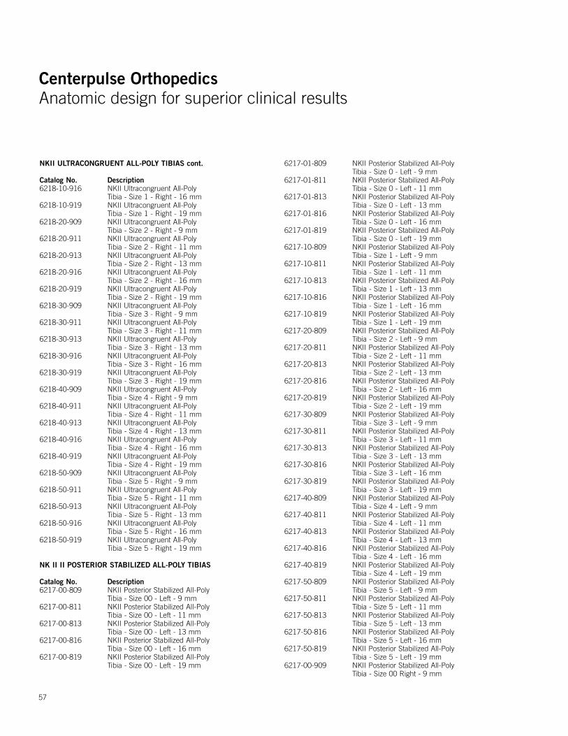
Centerpulse OrthopedicsAnatomic design for superior clinical results
Centerpulse OrthopedicsAnatomic design for superior clinical results
57
NKII ULTRACONGRUENT ALL-POLY TIBIAS cont.
Catalog No. Description6218-10-916 NKII Ultracongruent All-Poly
Tibia - Size 1 - Right - 16 mm 6218-10-919 NKII Ultracongruent All-Poly
Tibia - Size 1 - Right - 19 mm6218-20-909 NKII Ultracongruent All-Poly
Tibia - Size 2 - Right - 9 mm6218-20-911 NKII Ultracongruent All-Poly
Tibia - Size 2 - Right - 11 mm 6218-20-913 NKII Ultracongruent All-Poly
Tibia - Size 2 - Right - 13 mm6218-20-916 NKII Ultracongruent All-Poly
Tibia - Size 2 - Right - 16 mm 6218-20-919 NKII Ultracongruent All-Poly
Tibia - Size 2 - Right - 19 mm6218-30-909 NKII Ultracongruent All-Poly
Tibia - Size 3 - Right - 9 mm6218-30-911 NKII Ultracongruent All-Poly
Tibia - Size 3 - Right - 11 mm6218-30-913 NKII Ultracongruent All-Poly
Tibia - Size 3 - Right - 13 mm6218-30-916 NKII Ultracongruent All-Poly
Tibia - Size 3 - Right - 16 mm 6218-30-919 NKII Ultracongruent All-Poly
Tibia - Size 3 - Right - 19 mm 6218-40-909 NKII Ultracongruent All-Poly
Tibia - Size 4 - Right - 9 mm6218-40-911 NKII Ultracongruent All-Poly
Tibia - Size 4 - Right - 11 mm6218-40-913 NKII Ultracongruent All-Poly
Tibia - Size 4 - Right - 13 mm6218-40-916 NKII Ultracongruent All-Poly
Tibia - Size 4 - Right - 16 mm6218-40-919 NKII Ultracongruent All-Poly
Tibia - Size 4 - Right - 19 mm6218-50-909 NKII Ultracongruent All-Poly
Tibia - Size 5 - Right - 9 mm6218-50-911 NKII Ultracongruent All-Poly
Tibia - Size 5 - Right - 11 mm6218-50-913 NKII Ultracongruent All-Poly
Tibia - Size 5 - Right - 13 mm6218-50-916 NKII Ultracongruent All-Poly
Tibia - Size 5 - Right - 16 mm6218-50-919 NKII Ultracongruent All-Poly
Tibia - Size 5 - Right - 19 mm
NK II II POSTERIOR STABILIZED ALL-POLY TIBIAS
Catalog No. Description6217-00-809 NKII Posterior Stabilized All-Poly
Tibia - Size 00 - Left - 9 mm6217-00-811 NKII Posterior Stabilized All-Poly
Tibia - Size 00 - Left - 11 mm 6217-00-813 NKII Posterior Stabilized All-Poly
Tibia - Size 00 - Left - 13 mm6217-00-816 NKII Posterior Stabilized All-Poly
Tibia - Size 00 - Left - 16 mm6217-00-819 NKII Posterior Stabilized All-Poly
Tibia - Size 00 - Left - 19 mm
6217-01-809 NKII Posterior Stabilized All-Poly Tibia - Size 0 - Left - 9 mm
6217-01-811 NKII Posterior Stabilized All-Poly Tibia - Size 0 - Left - 11 mm
6217-01-813 NKII Posterior Stabilized All-Poly Tibia - Size 0 - Left - 13 mm
6217-01-816 NKII Posterior Stabilized All-Poly Tibia - Size 0 - Left - 16 mm
6217-01-819 NKII Posterior Stabilized All-Poly Tibia - Size 0 - Left - 19 mm
6217-10-809 NKII Posterior Stabilized All-Poly Tibia - Size 1 - Left - 9 mm
6217-10-811 NKII Posterior Stabilized All-Poly Tibia - Size 1 - Left - 11 mm
6217-10-813 NKII Posterior Stabilized All-Poly Tibia - Size 1 - Left - 13 mm
6217-10-816 NKII Posterior Stabilized All-Poly Tibia - Size 1 - Left - 16 mm
6217-10-819 NKII Posterior Stabilized All-Poly Tibia - Size 1 - Left - 19 mm
6217-20-809 NKII Posterior Stabilized All-Poly Tibia - Size 2 - Left - 9 mm
6217-20-811 NKII Posterior Stabilized All-Poly Tibia - Size 2 - Left - 11 mm
6217-20-813 NKII Posterior Stabilized All-Poly Tibia - Size 2 - Left - 13 mm
6217-20-816 NKII Posterior Stabilized All-Poly Tibia - Size 2 - Left - 16 mm
6217-20-819 NKII Posterior Stabilized All-Poly Tibia - Size 2 - Left - 19 mm
6217-30-809 NKII Posterior Stabilized All-Poly Tibia - Size 3 - Left - 9 mm
6217-30-811 NKII Posterior Stabilized All-Poly Tibia - Size 3 - Left - 11 mm
6217-30-813 NKII Posterior Stabilized All-Poly Tibia - Size 3 - Left - 13 mm
6217-30-816 NKII Posterior Stabilized All-Poly Tibia - Size 3 - Left - 16 mm
6217-30-819 NKII Posterior Stabilized All-Poly Tibia - Size 3 - Left - 19 mm
6217-40-809 NKII Posterior Stabilized All-Poly Tibia - Size 4 - Left - 9 mm
6217-40-811 NKII Posterior Stabilized All-Poly Tibia - Size 4 - Left - 11 mm
6217-40-813 NKII Posterior Stabilized All-Poly Tibia - Size 4 - Left - 13 mm
6217-40-816 NKII Posterior Stabilized All-Poly Tibia - Size 4 - Left - 16 mm
6217-40-819 NKII Posterior Stabilized All-Poly Tibia - Size 4 - Left - 19 mm
6217-50-809 NKII Posterior Stabilized All-Poly Tibia - Size 5 - Left - 9 mm
6217-50-811 NKII Posterior Stabilized All-Poly Tibia - Size 5 - Left - 11 mm
6217-50-813 NKII Posterior Stabilized All-Poly Tibia - Size 5 - Left - 13 mm
6217-50-816 NKII Posterior Stabilized All-Poly Tibia - Size 5 - Left - 16 mm
6217-50-819 NKII Posterior Stabilized All-Poly Tibia - Size 5 - Left - 19 mm
6217-00-909 NKII Posterior Stabilized All-Poly Tibia - Size 00 Right - 9 mm
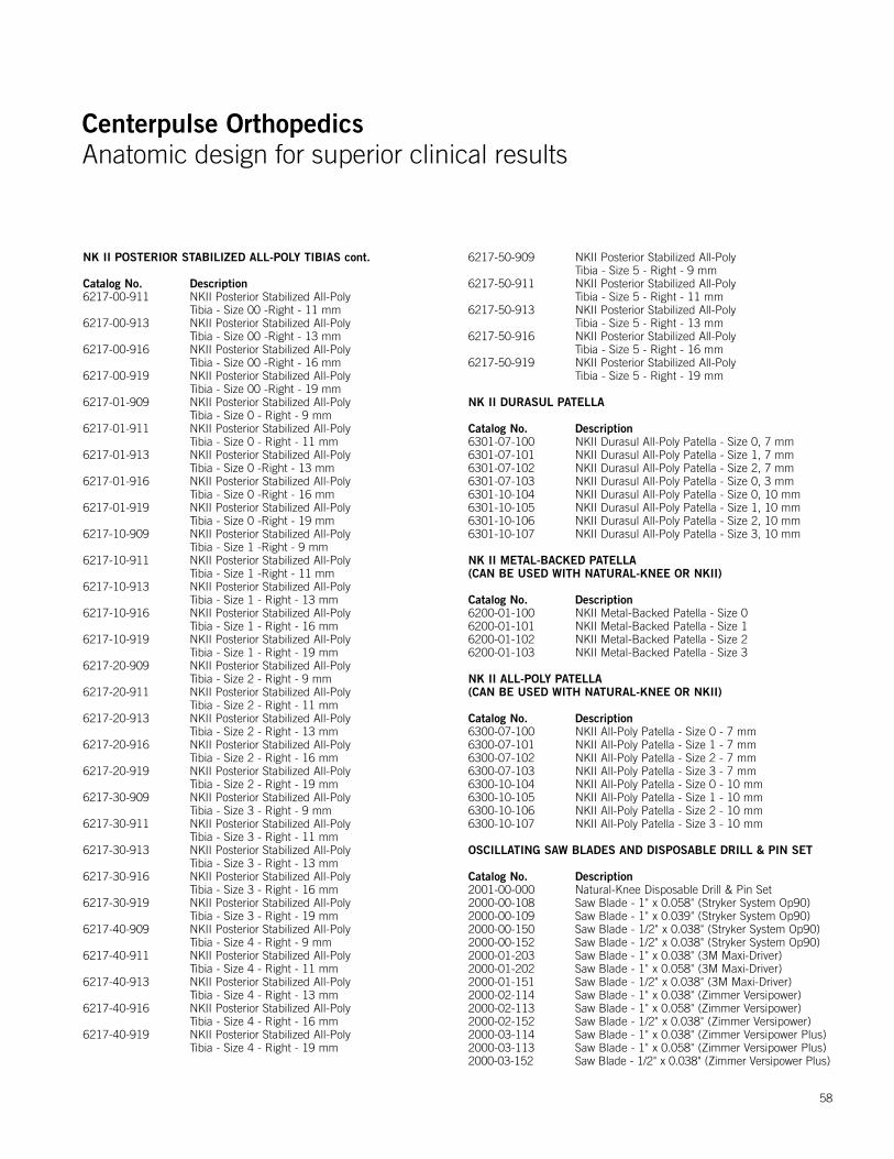
Centerpulse OrthopedicsAnatomic design for superior clinical results
Centerpulse OrthopedicsAnatomic design for superior clinical results
58
NK II POSTERIOR STABILIZED ALL-POLY TIBIAS cont.
Catalog No. Description6217-00-911 NKII Posterior Stabilized All-Poly
Tibia - Size 00 -Right - 11 mm 6217-00-913 NKII Posterior Stabilized All-Poly
Tibia - Size 00 -Right - 13 mm6217-00-916 NKII Posterior Stabilized All-Poly
Tibia - Size 00 -Right - 16 mm6217-00-919 NKII Posterior Stabilized All-Poly
Tibia - Size 00 -Right - 19 mm6217-01-909 NKII Posterior Stabilized All-Poly
Tibia - Size 0 - Right - 9 mm6217-01-911 NKII Posterior Stabilized All-Poly
Tibia - Size 0 - Right - 11 mm6217-01-913 NKII Posterior Stabilized All-Poly
Tibia - Size 0 -Right - 13 mm6217-01-916 NKII Posterior Stabilized All-Poly
Tibia - Size 0 -Right - 16 mm6217-01-919 NKII Posterior Stabilized All-Poly
Tibia - Size 0 -Right - 19 mm6217-10-909 NKII Posterior Stabilized All-Poly
Tibia - Size 1 -Right - 9 mm6217-10-911 NKII Posterior Stabilized All-Poly
Tibia - Size 1 -Right - 11 mm6217-10-913 NKII Posterior Stabilized All-Poly
Tibia - Size 1 - Right - 13 mm6217-10-916 NKII Posterior Stabilized All-Poly
Tibia - Size 1 - Right - 16 mm6217-10-919 NKII Posterior Stabilized All-Poly
Tibia - Size 1 - Right - 19 mm6217-20-909 NKII Posterior Stabilized All-Poly
Tibia - Size 2 - Right - 9 mm6217-20-911 NKII Posterior Stabilized All-Poly
Tibia - Size 2 - Right - 11 mm6217-20-913 NKII Posterior Stabilized All-Poly
Tibia - Size 2 - Right - 13 mm6217-20-916 NKII Posterior Stabilized All-Poly
Tibia - Size 2 - Right - 16 mm6217-20-919 NKII Posterior Stabilized All-Poly
Tibia - Size 2 - Right - 19 mm6217-30-909 NKII Posterior Stabilized All-Poly
Tibia - Size 3 - Right - 9 mm6217-30-911 NKII Posterior Stabilized All-Poly
Tibia - Size 3 - Right - 11 mm6217-30-913 NKII Posterior Stabilized All-Poly
Tibia - Size 3 - Right - 13 mm6217-30-916 NKII Posterior Stabilized All-Poly
Tibia - Size 3 - Right - 16 mm6217-30-919 NKII Posterior Stabilized All-Poly
Tibia - Size 3 - Right - 19 mm6217-40-909 NKII Posterior Stabilized All-Poly
Tibia - Size 4 - Right - 9 mm6217-40-911 NKII Posterior Stabilized All-Poly
Tibia - Size 4 - Right - 11 mm6217-40-913 NKII Posterior Stabilized All-Poly
Tibia - Size 4 - Right - 13 mm 6217-40-916 NKII Posterior Stabilized All-Poly
Tibia - Size 4 - Right - 16 mm6217-40-919 NKII Posterior Stabilized All-Poly
Tibia - Size 4 - Right - 19 mm
6217-50-909 NKII Posterior Stabilized All-Poly Tibia - Size 5 - Right - 9 mm
6217-50-911 NKII Posterior Stabilized All-Poly Tibia - Size 5 - Right - 11 mm
6217-50-913 NKII Posterior Stabilized All-Poly Tibia - Size 5 - Right - 13 mm
6217-50-916 NKII Posterior Stabilized All-Poly Tibia - Size 5 - Right - 16 mm
6217-50-919 NKII Posterior Stabilized All-Poly Tibia - Size 5 - Right - 19 mm
NK II DURASUL PATELLA
Catalog No. Description6301-07-100 NKII Durasul All-Poly Patella - Size 0, 7 mm6301-07-101 NKII Durasul All-Poly Patella - Size 1, 7 mm6301-07-102 NKII Durasul All-Poly Patella - Size 2, 7 mm6301-07-103 NKII Durasul All-Poly Patella - Size 0, 3 mm6301-10-104 NKII Durasul All-Poly Patella - Size 0, 10 mm6301-10-105 NKII Durasul All-Poly Patella - Size 1, 10 mm6301-10-106 NKII Durasul All-Poly Patella - Size 2, 10 mm6301-10-107 NKII Durasul All-Poly Patella - Size 3, 10 mm
NK II METAL-BACKED PATELLA (CAN BE USED WITH NATURAL-KNEE OR NKII)
Catalog No. Description6200-01-100 NKII Metal-Backed Patella - Size 06200-01-101 NKII Metal-Backed Patella - Size 16200-01-102 NKII Metal-Backed Patella - Size 26200-01-103 NKII Metal-Backed Patella - Size 3
NK II ALL-POLY PATELLA (CAN BE USED WITH NATURAL-KNEE OR NKII)
Catalog No. Description6300-07-100 NKII All-Poly Patella - Size 0 - 7 mm 6300-07-101 NKII All-Poly Patella - Size 1 - 7 mm 6300-07-102 NKII All-Poly Patella - Size 2 - 7 mm 6300-07-103 NKII All-Poly Patella - Size 3 - 7 mm 6300-10-104 NKII All-Poly Patella - Size 0 - 10 mm 6300-10-105 NKII All-Poly Patella - Size 1 - 10 mm 6300-10-106 NKII All-Poly Patella - Size 2 - 10 mm 6300-10-107 NKII All-Poly Patella - Size 3 - 10 mm
OSCILLATING SAW BLADES AND DISPOSABLE DRILL & PIN SET
Catalog No. Description2001-00-000 Natural-Knee Disposable Drill & Pin Set2000-00-108 Saw Blade - 1" x 0.058" (Stryker System Op90)2000-00-109 Saw Blade - 1" x 0.039" (Stryker System Op90)2000-00-150 Saw Blade - 1/2" x 0.038" (Stryker System Op90)2000-00-152 Saw Blade - 1/2" x 0.038" (Stryker System Op90)2000-01-203 Saw Blade - 1" x 0.038" (3M Maxi-Driver)2000-01-202 Saw Blade - 1" x 0.058" (3M Maxi-Driver)2000-01-151 Saw Blade - 1/2" x 0.038" (3M Maxi-Driver)2000-02-114 Saw Blade - 1" x 0.038" (Zimmer Versipower)2000-02-113 Saw Blade - 1" x 0.058" (Zimmer Versipower)2000-02-152 Saw Blade - 1/2" x 0.038" (Zimmer Versipower)2000-03-114 Saw Blade - 1" x 0.038" (Zimmer Versipower Plus)2000-03-113 Saw Blade - 1" x 0.058" (Zimmer Versipower Plus)2000-03-152 Saw Blade - 1/2" x 0.038" (Zimmer Versipower Plus)
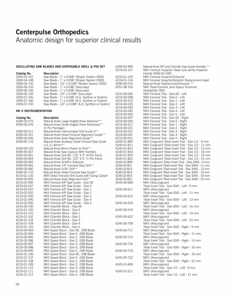
Centerpulse OrthopedicsAnatomic design for superior clinical results
Centerpulse OrthopedicsAnatomic design for superior clinical results
59
OSCILLATING SAW BLADES AND DISPOSABLE DRILL & PIN SET
Catalog No. Description2000-04-107 Saw Blade - 1" x 0.058" (Stryker System 2000)2000-04-108 Saw Blade - 1" x 0.058" (Stryker System 2000)2000-04-150 Saw Blade - 1/2" x 0.038" (Stryker System 2000)2000-06-105 Saw Blade - 1" x 0.038" (Aesculap)2000-06-106 Saw Blade - 1" x 0.058" (Aesculap)2000-06-150 Saw Blade - 1/2" x 0.038" (Aesculap)2000-07-105 Saw Blade - 1" x 0.038" (A.O. Synthes or Sodem)2000-07-106 Saw Blade - 1" x 0.058" (A.O. Synthes or Sodem)2000-07-150 Saw Blade - 1/2" x 0.038" (A.O. Synthes or Sodem)
NK II INSTRUMENTATION
Catalog No. Description6290-00-075 Natural-Knee Large Angled Knee Retractor**6290-00-076 Natural-Knee Small Angled Knee Retractors**
(3 Per Package)6290-00-011 Natural-Knee Intercondylar Drill Guide II**6290-00-101 Natural-Knee Distal Femoral Alignment Guide**6290-00-000 Natural-Knee Axial Alignment Guide**6290-00-116 Natural-Knee Auxiliary Distal Femoral Saw Guide
(+2,-2,-4mm)**6290-00-125 Natural-Knee 8mm Fluted Im Rod**6290-00-057 Natural-Knee Saw Capture With Handles 6290-00-061 Natural-Knee Drill Bit .125" X 3" (4 Per Pack)6290-00-063 Natural-Knee Drill Bit .125" X 5" (1 Per Pack)6290-00-065 Natural-Knee Drill/Pin Extractor 6290-00-062 Natural-Knee 1/4" Femoral Stop Drill**6290-00-060 Natural-Knee 5/16" Drill**6290-00-110 Natural-Knee Distal Femoral Saw Guide**6219-01-120 NKII Distal Femoral Drill Guide with Sizing Caliper6290-00-005 Natural-Knee Axial Alignment Rod**6219-02-006 NKII Femoral A/P Saw Guide - Size 006219-02-007 NKII Femoral A/P Saw Guide - Size 06219-02-010 NKII Femoral A/P Saw Guide - Size 16219-02-020 NKII Femoral A/P Saw Guide - Size 26219-02-030 NKII Femoral A/P Saw Guide - Size 36219-02-040 NKII Femoral A/P Saw Guide - Size 46219-02-050 NKII Femoral A/P Saw Guide - Size 56216-00-100 NKII Chamfer Block - Size 006216-01-100 NKII Chamfer Block - Size 06216-01-101 NKII Chamfer Block - Size 16216-01-102 NKII Chamfer Block - Size 26216-01-103 NKII Chamfer Block - Size 36216-01-104 NKII Chamfer Block - Size 46216-01-105 NKII Chamfer Block - Size 56216-00-093 NKII Speed Block - Size 00, .058 Blade6216-00-094 NKII Speed Block - Size 0, .058 Blade6216-00-095 NKII Speed Block - Size 1, .058 Blade6216-00-096 NKII Speed Block - Size 2, .058 Blade6216-00-097 NKII Speed Block - Size 3, .058 Blade6216-00-098 NKII Speed Block - Size 4, .058 Blade6216-00-099 NKII Speed Block - Size 5, .058 Blade6216-01-106 NKII Speed Block - Size 00, .038 Blade6216-01-107 NKII Speed Block - Size 0, .038 Blade6216-01-108 NKII Speed Block - Size 1, .038 Blade6216-01-109 NKII Speed Block - Size 2, .038 Blade6216-01-110 NKII Speed Block - Size 3, .038 Blade6216-01-111 NKII Speed Block - Size 4, .038 Blade6216-01-112 NKII Speed Block - Size 5, .038 Blade
6290-00-499 Natural-Knee A/P and Chamfer Saw Guide Handles **6219-03-101 NKII Femoral Impactor Head (use w/Hip Impactor
Handle 9206-02-100)6216-01-120 NKII Femoral Impactor/Extractor6216-01-124 NKII Femoral Impactor/Extractor Replacement Head6290-00-015 Natural-Knee Slaphammer/Extractor **6291-08-100 NKII Tibial-Femoral Joint Space Tensioner
(Availability TBA)6216-00-006 NKII Femoral Trial - Size 00 - Left6216-00-008 NKII Femoral Trial - Size 0 - Left6216-00-010 NKII Femoral Trial - Size 1 - Left6216-00-020 NKII Femoral Trial - Size 2 - Left6216-00-030 NKII Femoral Trial - Size 3 - Left6216-00-040 NKII Femoral Trial - Size 4 - Left6216-00-050 NKII Femoral Trial - Size 5 - Left6216-00-007 NKII Femoral Trial - Size 00 - Right6216-00-009 NKII Femoral Trial - Size 0 - Right6216-00-011 NKII Femoral Trial - Size 1 - Right6216-00-021 NKII Femoral Trial - Size 2 - Right6216-00-031 NKII Femoral Trial - Size 3 - Right6216-00-041 NKII Femoral Trial - Size 4 - Right6216-00-051 NKII Femoral Trial - Size 5 - Right6240-01-809 NKII Congruent Tibial Insert Trial - Size 1/2 - 9 mm6240-01-811 NKII Congruent Tibial Insert Trial - Size 1/2 - 11 mm6240-01-813 NKII Congruent Tibial Insert Trial - Size 1/2 - 13 mm6240-01-816 NKII Congruent Tibial Insert Trial - Size 1/2 - 16 mm6240-01-819 NKII Congruent Tibial Insert Trial - Size 1/2 - 19 mm6240-01-822 NKII Congruent Tibial Insert Trial - Size 1/2 - 22 mm6240-02-809 NKII Congruent Tibial Insert Trial - Size 3/4/5 - 9 mm6240-02-811 NKII Congruent Tibial Insert Trial - Size 3/4/5 - 11 mm6240-02-813 NKII Congruent Tibial Insert Trial - Size 3/4/5 - 13 mm6240-02-816 NKII Congruent Tibial Insert Trial - Size 3/4/5 - 16 mm6240-02-819 NKII Congruent Tibial Insert Trial - Size 3/4/5 - 19 mm6240-02-822 NKII Congruent Tibial Insert Trial - Size 3/4/5 - 22 mm6245-00-609 NKII Ultracongruent
Tibial Insert Trial - Size 00/0 - Left - 9 mm6245-00-611 NKII Ultracongruent
Tibial Insert Trial - Size 00/0 - Left - 11 mm 6245-00-613 NKII Ultracongruent
Tibial Insert Trial - Size 00/0 - Left - 13 mm6245-00-616 NKII Ultracongruent
Tibial Insert Trial - Size 00/0 - Left - 16 mm 6245-00-619 NKII Ultracongruent
Tibial Insert Trial - Size 00/0 - Left - 19 mm 6245-00-622 NKII Ultracongruent
Tibial Insert Trial - Size 00/0 - Left - 22 mm6245-00-709 NKII Ultracongruent
Tibial Insert Trial - Size 00/0 - Right - 9 mm6245-00-711 NKII Ultracongruent
Tibial Insert Trial - Size 00/0 - Right - 11 mm6245-00-713 NKII Ultracongruent
Tibial Insert Trial - Size 00/0 - Right - 13 mm6245-00-716 NKII Ultracongruent
Tibial Insert Trial - Size 00/0 - Right - 16 mm 6245-00-719 NKII Ultracongruent
Tibial Insert Trial - Size 00/0 - Right - 19 mm6245-00-722 NKII Ultracongruent
Tibial Insert Trial - Size 00/0 - Right - 22 mm6245-01-609 NKII Ultracongruent
Tibial Insert Trial - Size 1/2 - Left - 9 mm6245-01-611 NKII Ultracongruent
Tibial Insert Trial - Size 1/2 - Left - 11 mm
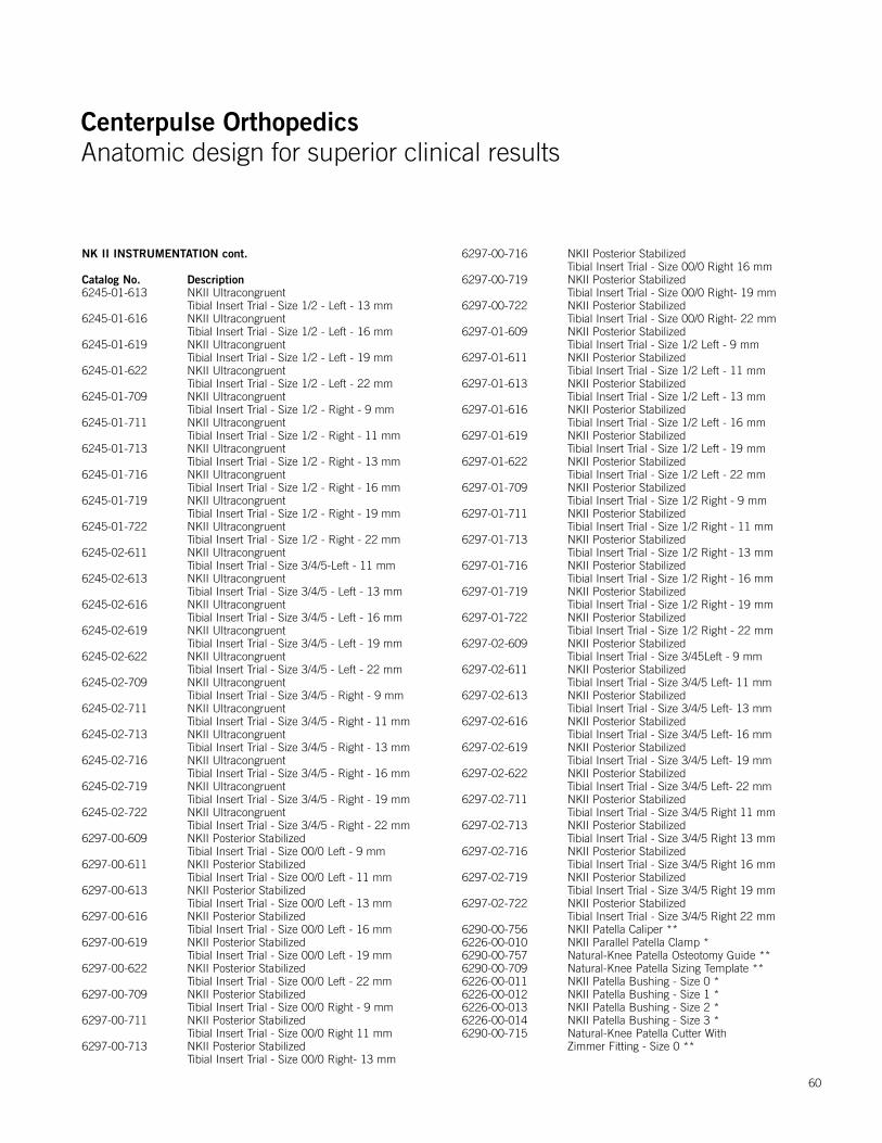
Centerpulse OrthopedicsAnatomic design for superior clinical results
Centerpulse OrthopedicsAnatomic design for superior clinical results
NK II INSTRUMENTATION cont.
Catalog No. Description6245-01-613 NKII Ultracongruent
Tibial Insert Trial - Size 1/2 - Left - 13 mm6245-01-616 NKII Ultracongruent
Tibial Insert Trial - Size 1/2 - Left - 16 mm 6245-01-619 NKII Ultracongruent
Tibial Insert Trial - Size 1/2 - Left - 19 mm6245-01-622 NKII Ultracongruent
Tibial Insert Trial - Size 1/2 - Left - 22 mm 6245-01-709 NKII Ultracongruent
Tibial Insert Trial - Size 1/2 - Right - 9 mm 6245-01-711 NKII Ultracongruent
Tibial Insert Trial - Size 1/2 - Right - 11 mm6245-01-713 NKII Ultracongruent
Tibial Insert Trial - Size 1/2 - Right - 13 mm6245-01-716 NKII Ultracongruent
Tibial Insert Trial - Size 1/2 - Right - 16 mm6245-01-719 NKII Ultracongruent
Tibial Insert Trial - Size 1/2 - Right - 19 mm6245-01-722 NKII Ultracongruent
Tibial Insert Trial - Size 1/2 - Right - 22 mm6245-02-611 NKII Ultracongruent
Tibial Insert Trial - Size 3/4/5-Left - 11 mm6245-02-613 NKII Ultracongruent
Tibial Insert Trial - Size 3/4/5 - Left - 13 mm6245-02-616 NKII Ultracongruent
Tibial Insert Trial - Size 3/4/5 - Left - 16 mm6245-02-619 NKII Ultracongruent
Tibial Insert Trial - Size 3/4/5 - Left - 19 mm6245-02-622 NKII Ultracongruent
Tibial Insert Trial - Size 3/4/5 - Left - 22 mm6245-02-709 NKII Ultracongruent
Tibial Insert Trial - Size 3/4/5 - Right - 9 mm6245-02-711 NKII Ultracongruent
Tibial Insert Trial - Size 3/4/5 - Right - 11 mm 6245-02-713 NKII Ultracongruent
Tibial Insert Trial - Size 3/4/5 - Right - 13 mm 6245-02-716 NKII Ultracongruent
Tibial Insert Trial - Size 3/4/5 - Right - 16 mm 6245-02-719 NKII Ultracongruent
Tibial Insert Trial - Size 3/4/5 - Right - 19 mm 6245-02-722 NKII Ultracongruent
Tibial Insert Trial - Size 3/4/5 - Right - 22 mm 6297-00-609 NKII Posterior Stabilized
Tibial Insert Trial - Size 00/0 Left - 9 mm6297-00-611 NKII Posterior Stabilized
Tibial Insert Trial - Size 00/0 Left - 11 mm6297-00-613 NKII Posterior Stabilized
Tibial Insert Trial - Size 00/0 Left - 13 mm6297-00-616 NKII Posterior Stabilized
Tibial Insert Trial - Size 00/0 Left - 16 mm6297-00-619 NKII Posterior Stabilized
Tibial Insert Trial - Size 00/0 Left - 19 mm6297-00-622 NKII Posterior Stabilized
Tibial Insert Trial - Size 00/0 Left - 22 mm6297-00-709 NKII Posterior Stabilized
Tibial Insert Trial - Size 00/0 Right - 9 mm6297-00-711 NKII Posterior Stabilized
Tibial Insert Trial - Size 00/0 Right 11 mm6297-00-713 NKII Posterior Stabilized
Tibial Insert Trial - Size 00/0 Right- 13 mm
6297-00-716 NKII Posterior Stabilized Tibial Insert Trial - Size 00/0 Right 16 mm
6297-00-719 NKII Posterior Stabilized Tibial Insert Trial - Size 00/0 Right- 19 mm
6297-00-722 NKII Posterior Stabilized Tibial Insert Trial - Size 00/0 Right- 22 mm
6297-01-609 NKII Posterior Stabilized Tibial Insert Trial - Size 1/2 Left - 9 mm
6297-01-611 NKII Posterior Stabilized Tibial Insert Trial - Size 1/2 Left - 11 mm
6297-01-613 NKII Posterior Stabilized Tibial Insert Trial - Size 1/2 Left - 13 mm
6297-01-616 NKII Posterior Stabilized Tibial Insert Trial - Size 1/2 Left - 16 mm
6297-01-619 NKII Posterior Stabilized Tibial Insert Trial - Size 1/2 Left - 19 mm
6297-01-622 NKII Posterior Stabilized Tibial Insert Trial - Size 1/2 Left - 22 mm
6297-01-709 NKII Posterior Stabilized Tibial Insert Trial - Size 1/2 Right - 9 mm
6297-01-711 NKII Posterior Stabilized Tibial Insert Trial - Size 1/2 Right - 11 mm
6297-01-713 NKII Posterior Stabilized Tibial Insert Trial - Size 1/2 Right - 13 mm
6297-01-716 NKII Posterior Stabilized Tibial Insert Trial - Size 1/2 Right - 16 mm
6297-01-719 NKII Posterior Stabilized Tibial Insert Trial - Size 1/2 Right - 19 mm
6297-01-722 NKII Posterior Stabilized Tibial Insert Trial - Size 1/2 Right - 22 mm
6297-02-609 NKII Posterior Stabilized Tibial Insert Trial - Size 3/45Left - 9 mm
6297-02-611 NKII Posterior Stabilized Tibial Insert Trial - Size 3/4/5 Left- 11 mm
6297-02-613 NKII Posterior Stabilized Tibial Insert Trial - Size 3/4/5 Left- 13 mm
6297-02-616 NKII Posterior Stabilized Tibial Insert Trial - Size 3/4/5 Left- 16 mm
6297-02-619 NKII Posterior Stabilized Tibial Insert Trial - Size 3/4/5 Left- 19 mm
6297-02-622 NKII Posterior Stabilized Tibial Insert Trial - Size 3/4/5 Left- 22 mm
6297-02-711 NKII Posterior Stabilized Tibial Insert Trial - Size 3/4/5 Right 11 mm
6297-02-713 NKII Posterior Stabilized Tibial Insert Trial - Size 3/4/5 Right 13 mm
6297-02-716 NKII Posterior Stabilized Tibial Insert Trial - Size 3/4/5 Right 16 mm
6297-02-719 NKII Posterior Stabilized Tibial Insert Trial - Size 3/4/5 Right 19 mm
6297-02-722 NKII Posterior Stabilized Tibial Insert Trial - Size 3/4/5 Right 22 mm
6290-00-756 NKII Patella Caliper **6226-00-010 NKII Parallel Patella Clamp *6290-00-757 Natural-Knee Patella Osteotomy Guide **6290-00-709 Natural-Knee Patella Sizing Template **6226-00-011 NKII Patella Bushing - Size 0 *6226-00-012 NKII Patella Bushing - Size 1 *6226-00-013 NKII Patella Bushing - Size 2 *6226-00-014 NKII Patella Bushing - Size 3 *6290-00-715 Natural-Knee Patella Cutter With
Zimmer Fitting - Size 0 **
60
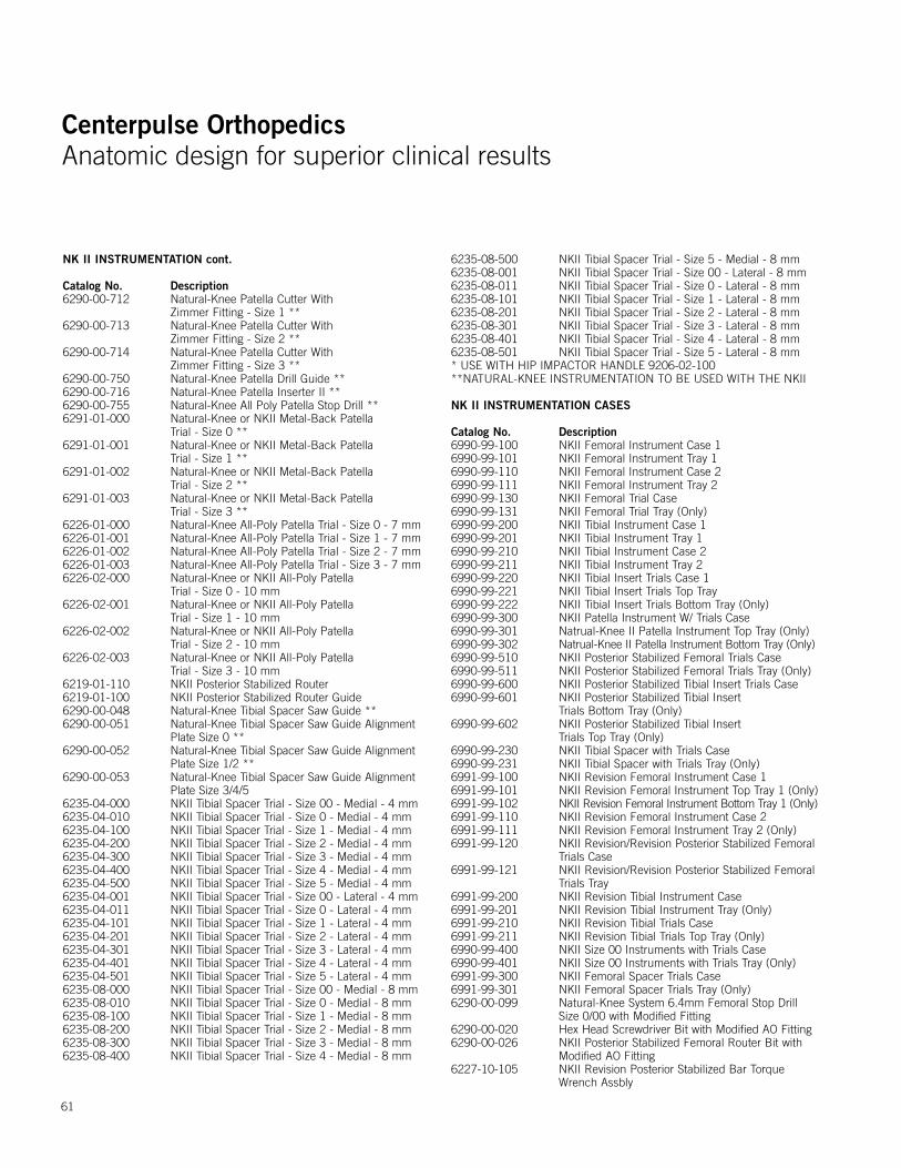
Centerpulse OrthopedicsAnatomic design for superior clinical results
Centerpulse OrthopedicsAnatomic design for superior clinical results
NK II INSTRUMENTATION cont.
Catalog No. Description6290-00-712 Natural-Knee Patella Cutter With
Zimmer Fitting - Size 1 **6290-00-713 Natural-Knee Patella Cutter With
Zimmer Fitting - Size 2 **6290-00-714 Natural-Knee Patella Cutter With
Zimmer Fitting - Size 3 **6290-00-750 Natural-Knee Patella Drill Guide **6290-00-716 Natural-Knee Patella Inserter II **6290-00-755 Natural-Knee All Poly Patella Stop Drill **6291-01-000 Natural-Knee or NKII Metal-Back Patella
Trial - Size 0 **6291-01-001 Natural-Knee or NKII Metal-Back Patella
Trial - Size 1 **6291-01-002 Natural-Knee or NKII Metal-Back Patella
Trial - Size 2 **6291-01-003 Natural-Knee or NKII Metal-Back Patella
Trial - Size 3 **6226-01-000 Natural-Knee All-Poly Patella Trial - Size 0 - 7 mm 6226-01-001 Natural-Knee All-Poly Patella Trial - Size 1 - 7 mm6226-01-002 Natural-Knee All-Poly Patella Trial - Size 2 - 7 mm6226-01-003 Natural-Knee All-Poly Patella Trial - Size 3 - 7 mm6226-02-000 Natural-Knee or NKII All-Poly Patella
Trial - Size 0 - 10 mm6226-02-001 Natural-Knee or NKII All-Poly Patella
Trial - Size 1 - 10 mm6226-02-002 Natural-Knee or NKII All-Poly Patella
Trial - Size 2 - 10 mm6226-02-003 Natural-Knee or NKII All-Poly Patella
Trial - Size 3 - 10 mm6219-01-110 NKII Posterior Stabilized Router 6219-01-100 NKII Posterior Stabilized Router Guide6290-00-048 Natural-Knee Tibial Spacer Saw Guide **6290-00-051 Natural-Knee Tibial Spacer Saw Guide Alignment
Plate Size 0 **6290-00-052 Natural-Knee Tibial Spacer Saw Guide Alignment
Plate Size 1/2 **6290-00-053 Natural-Knee Tibial Spacer Saw Guide Alignment
Plate Size 3/4/56235-04-000 NKII Tibial Spacer Trial - Size 00 - Medial - 4 mm 6235-04-010 NKII Tibial Spacer Trial - Size 0 - Medial - 4 mm 6235-04-100 NKII Tibial Spacer Trial - Size 1 - Medial - 4 mm 6235-04-200 NKII Tibial Spacer Trial - Size 2 - Medial - 4 mm 6235-04-300 NKII Tibial Spacer Trial - Size 3 - Medial - 4 mm 6235-04-400 NKII Tibial Spacer Trial - Size 4 - Medial - 4 mm 6235-04-500 NKII Tibial Spacer Trial - Size 5 - Medial - 4 mm 6235-04-001 NKII Tibial Spacer Trial - Size 00 - Lateral - 4 mm 6235-04-011 NKII Tibial Spacer Trial - Size 0 - Lateral - 4 mm 6235-04-101 NKII Tibial Spacer Trial - Size 1 - Lateral - 4 mm 6235-04-201 NKII Tibial Spacer Trial - Size 2 - Lateral - 4 mm 6235-04-301 NKII Tibial Spacer Trial - Size 3 - Lateral - 4 mm 6235-04-401 NKII Tibial Spacer Trial - Size 4 - Lateral - 4 mm 6235-04-501 NKII Tibial Spacer Trial - Size 5 - Lateral - 4 mm 6235-08-000 NKII Tibial Spacer Trial - Size 00 - Medial - 8 mm6235-08-010 NKII Tibial Spacer Trial - Size 0 - Medial - 8 mm6235-08-100 NKII Tibial Spacer Trial - Size 1 - Medial - 8 mm6235-08-200 NKII Tibial Spacer Trial - Size 2 - Medial - 8 mm6235-08-300 NKII Tibial Spacer Trial - Size 3 - Medial - 8 mm6235-08-400 NKII Tibial Spacer Trial - Size 4 - Medial - 8 mm
6235-08-500 NKII Tibial Spacer Trial - Size 5 - Medial - 8 mm6235-08-001 NKII Tibial Spacer Trial - Size 00 - Lateral - 8 mm6235-08-011 NKII Tibial Spacer Trial - Size 0 - Lateral - 8 mm6235-08-101 NKII Tibial Spacer Trial - Size 1 - Lateral - 8 mm6235-08-201 NKII Tibial Spacer Trial - Size 2 - Lateral - 8 mm6235-08-301 NKII Tibial Spacer Trial - Size 3 - Lateral - 8 mm6235-08-401 NKII Tibial Spacer Trial - Size 4 - Lateral - 8 mm6235-08-501 NKII Tibial Spacer Trial - Size 5 - Lateral - 8 mm* USE WITH HIP IMPACTOR HANDLE 9206-02-100**NATURAL-KNEE INSTRUMENTATION TO BE USED WITH THE NKII
NK II INSTRUMENTATION CASES
Catalog No. Description6990-99-100 NKII Femoral Instrument Case 16990-99-101 NKII Femoral Instrument Tray 1 6990-99-110 NKII Femoral Instrument Case 26990-99-111 NKII Femoral Instrument Tray 2 6990-99-130 NKII Femoral Trial Case6990-99-131 NKII Femoral Trial Tray (Only)6990-99-200 NKII Tibial Instrument Case 16990-99-201 NKII Tibial Instrument Tray 1 6990-99-210 NKII Tibial Instrument Case 26990-99-211 NKII Tibial Instrument Tray 2 6990-99-220 NKII Tibial Insert Trials Case 16990-99-221 NKII Tibial Insert Trials Top Tray 6990-99-222 NKII Tibial Insert Trials Bottom Tray (Only)6990-99-300 NKII Patella Instrument W/ Trials Case 6990-99-301 Natrual-Knee II Patella Instrument Top Tray (Only) 6990-99-302 Natrual-Knee II Patella Instrument Bottom Tray (Only)6990-99-510 NKII Posterior Stabilized Femoral Trials Case6990-99-511 NKII Posterior Stabilized Femoral Trials Tray (Only)6990-99-600 NKII Posterior Stabilized Tibial Insert Trials Case6990-99-601 NKII Posterior Stabilized Tibial Insert
Trials Bottom Tray (Only)6990-99-602 NKII Posterior Stabilized Tibial Insert
Trials Top Tray (Only)6990-99-230 NKII Tibial Spacer with Trials Case6990-99-231 NKII Tibial Spacer with Trials Tray (Only)6991-99-100 NKII Revision Femoral Instrument Case 16991-99-101 NKII Revision Femoral Instrument Top Tray 1 (Only)6991-99-102 NKII Revision Femoral Instrument Bottom Tray 1 (Only)6991-99-110 NKII Revision Femoral Instrument Case 26991-99-111 NKII Revision Femoral Instrument Tray 2 (Only)6991-99-120 NKII Revision/Revision Posterior Stabilized Femoral
Trials Case6991-99-121 NKII Revision/Revision Posterior Stabilized Femoral
Trials Tray 6991-99-200 NKII Revision Tibial Instrument Case6991-99-201 NKII Revision Tibial Instrument Tray (Only)6991-99-210 NKII Revision Tibial Trials Case6991-99-211 NKII Revision Tibial Trials Top Tray (Only)6990-99-400 NKII Size 00 Instruments with Trials Case6990-99-401 NKII Size 00 Instruments with Trials Tray (Only)6991-99-300 NKII Femoral Spacer Trials Case6991-99-301 NKII Femoral Spacer Trials Tray (Only)6290-00-099 Natural-Knee System 6.4mm Femoral Stop Drill
Size 0/00 with Modified Fitting6290-00-020 Hex Head Screwdriver Bit with Modified AO Fitting6290-00-026 NKII Posterior Stabilized Femoral Router Bit with
Modified AO Fitting6227-10-105 NKII Revision Posterior Stabilized Bar Torque
Wrench Assbly
61
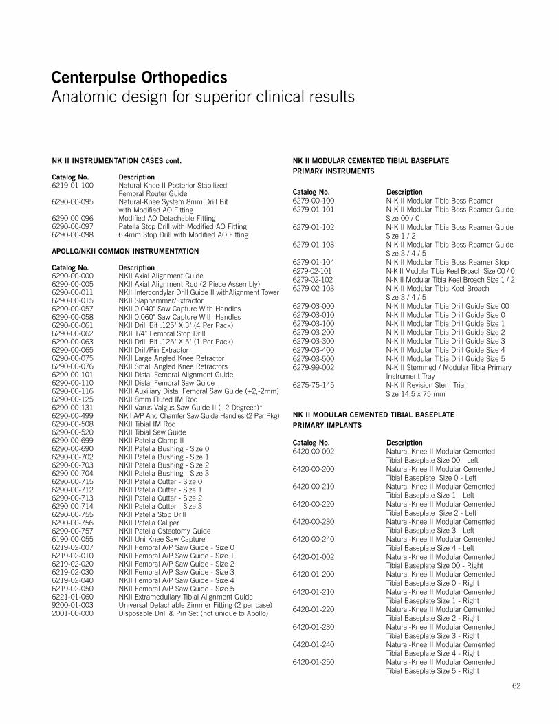
Centerpulse OrthopedicsAnatomic design for superior clinical results
Centerpulse OrthopedicsAnatomic design for superior clinical results
NK II INSTRUMENTATION CASES cont.
Catalog No. Description6219-01-100 Natural Knee II Posterior Stabilized
Femoral Router Guide6290-00-095 Natural-Knee System 8mm Drill Bit
with Modified AO Fitting6290-00-096 Modified AO Detachable Fitting6290-00-097 Patella Stop Drill with Modified AO Fitting6290-00-098 6.4mm Stop Drill with Modified AO Fitting
APOLLO/NKII COMMON INSTRUMENTATION
Catalog No. Description6290-00-000 NKII Axial Alignment Guide 6290-00-005 NKII Axial Alignment Rod (2 Piece Assembly)6290-00-011 NKII Intercondylar Drill Guide II withAlignment Tower6290-00-015 NKII Slaphammer/Extractor 6290-00-057 NKII 0.040" Saw Capture With Handles 6290-00-058 NKII 0.060" Saw Capture With Handles 6290-00-061 NKII Drill Bit .125" X 3" (4 Per Pack)6290-00-062 NKII 1/4" Femoral Stop Drill6290-00-063 NKII Drill Bit .125" X 5" (1 Per Pack)6290-00-065 NKII Drill/Pin Extractor 6290-00-075 NKII Large Angled Knee Retractor 6290-00-076 NKII Small Angled Knee Retractors 6290-00-101 NKII Distal Femoral Alignment Guide 6290-00-110 NKII Distal Femoral Saw Guide 6290-00-116 NKII Auxiliary Distal Femoral Saw Guide (+2,-2mm)6290-00-125 NKII 8mm Fluted IM Rod6290-00-131 NKII Varus Valgus Saw Guide II (+2 Degrees)*6290-00-499 NKII A/P And Chamfer Saw Guide Handles (2 Per Pkg)6290-00-508 NKII Tibial IM Rod6290-00-520 NKII Tibial Saw Guide6290-00-699 NKII Patella Clamp II6290-00-690 NKII Patella Bushing - Size 06290-00-702 NKII Patella Bushing - Size 16290-00-703 NKII Patella Bushing - Size 26290-00-704 NKII Patella Bushing - Size 36290-00-715 NKII Patella Cutter - Size 06290-00-712 NKII Patella Cutter - Size 16290-00-713 NKII Patella Cutter - Size 26290-00-714 NKII Patella Cutter - Size 36290-00-755 NKII Patella Stop Drill6290-00-756 NKII Patella Caliper6290-00-757 NKII Patella Osteotomy Guide6190-00-055 NKII Uni Knee Saw Capture6219-02-007 NKII Femoral A/P Saw Guide - Size 06219-02-010 NKII Femoral A/P Saw Guide - Size 16219-02-020 NKII Femoral A/P Saw Guide - Size 26219-02-030 NKII Femoral A/P Saw Guide - Size 36219-02-040 NKII Femoral A/P Saw Guide - Size 46219-02-050 NKII Femoral A/P Saw Guide - Size 56221-01-060 NKII Extramedullary Tibial Alignment Guide9200-01-003 Universal Detachable Zimmer Fitting (2 per case)2001-00-000 Disposable Drill & Pin Set (not unique to Apollo)
NK II MODULAR CEMENTED TIBIAL BASEPLATE PRIMARY INSTRUMENTS
Catalog No. Description6279-00-100 N-K II Modular Tibia Boss Reamer 6279-01-101 N-K II Modular Tibia Boss Reamer Guide Size 00 / 0 6279-01-102 N-K II Modular Tibia Boss Reamer Guide Size 1 / 2 6279-01-103 N-K II Modular Tibia Boss Reamer Guide Size 3 / 4 / 56279-01-104 N-K II Modular Tibia Boss Reamer Stop 6279-02-101 N-K II Modular Tibia Keel Broach Size 00 / 06279-02-102 N-K II Modular Tibia Keel Broach Size 1 / 26279-02-103 N-K II Modular Tibia Keel Broach Size 3 / 4 / 5 6279-03-000 N-K II Modular Tibia Drill Guide Size 006279-03-010 N-K II Modular Tibia Drill Guide Size 06279-03-100 N-K II Modular Tibia Drill Guide Size 16279-03-200 N-K II Modular Tibia Drill Guide Size 26279-03-300 N-K II Modular Tibia Drill Guide Size 36279-03-400 N-K II Modular Tibia Drill Guide Size 46279-03-500 N-K II Modular Tibia Drill Guide Size 56279-99-002 N-K II Stemmed / Modular Tibia Primary Instrument Tray6275-75-145 N-K II Revision Stem Trial Size 14.5 x 75 mm
NK II MODULAR CEMENTED TIBIAL BASEPLATE PRIMARY IMPLANTS
Catalog No. Description6420-00-002 Natural-Knee II Modular Cemented Tibial Baseplate Size 00 - Left6420-00-200 Natural-Knee II Modular Cemented Tibial Baseplate Size 0 - Left6420-00-210 Natural-Knee II Modular Cemented Tibial Baseplate Size 1 - Left6420-00-220 Natural-Knee II Modular Cemented Tibial Baseplate Size 2 - Left6420-00-230 Natural-Knee II Modular Cemented Tibial Baseplate Size 3 - Left6420-00-240 Natural-Knee II Modular Cemented Tibial Baseplate Size 4 - Left6420-01-002 Natural-Knee II Modular Cemented Tibial Baseplate Size 00 - Right6420-01-200 Natural-Knee II Modular Cemented Tibial Baseplate Size 0 - Right6420-01-210 Natural-Knee II Modular Cemented Tibial Baseplate Size 1 - Right6420-01-220 Natural-Knee II Modular Cemented Tibial Baseplate Size 2 - Right6420-01-230 Natural-Knee II Modular Cemented Tibial Baseplate Size 3 - Right6420-01-240 Natural-Knee II Modular Cemented Tibial Baseplate Size 4 - Right6420-01-250 Natural-Knee II Modular Cemented Tibial Baseplate Size 5 - Right
62

Centerpulse OrthopedicsAnatomic design for superior clinical results
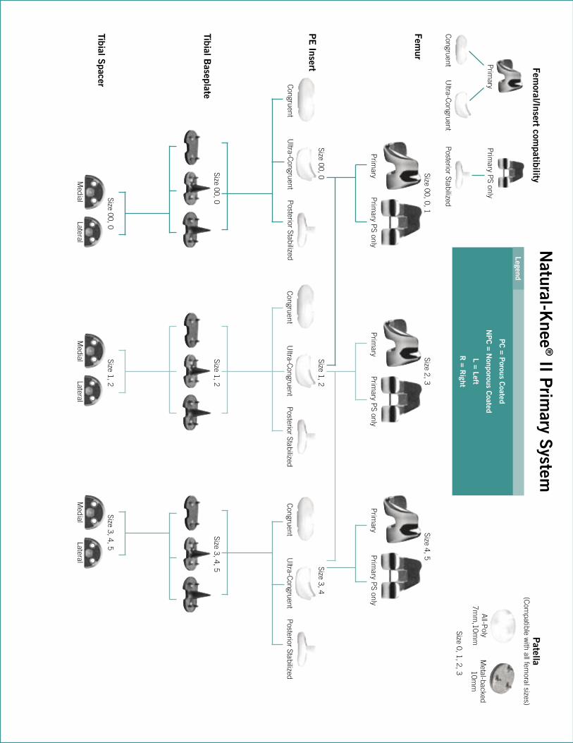
Centerpulse OrthopedicsAnatomic design for superior clinical results
Femur
PE
Insert
Tibial Baseplate
Tibial Spacer
Natural-K
nee® II P
rimary S
ystem
Prim
ary PS only
Femoral/Insert com
patibility
Prim
ary
Congruent
Ultra-C
ongruentP
osterior Stabilized
Congruent
Ultra-C
ongruentP
osterior Stabilized
Prim
ary PS only
Prim
aryP
rimary P
S onlyP
rimary
Prim
ary PS only
Prim
ary
Congruent
Ultra-C
ongruentP
osterior StabilizedC
ongruentU
ltra-Congruent
Posterior Stabilized
Patella
(Com
patible with all fem
oral sizes)
All-P
oly7m
m,10m
mM
etal-backed10m
m
Size 0, 1, 2, 3
Medial
LateralM
edialLateral
Medial
Lateral
Size 00, 0, 1Size 2, 3
Size 4, 5
Size 00, 0Size 1, 2
Size 3, 4
Size 00, 0Size 1, 2
Size 3, 4, 5
Size 00, 0Size 1, 2
Size 3, 4, 5
Legend
PC
= Porous C
oated
NP
C = N
onporous Coated
L = Left
R = R
ight
KneesApollo® Knee System Classic condylar knee replacement systemDurasul® Tribological System Highly crosslinked polyethylene that resists wear and agingNatural-Knee® System Anatomic design for superior clinical resultsUniSpacerTM Knee System No bone cuts. No compromises.
Severe Revision/Limb SalvageMOST OptionsTM System Modular knee and hip options for severe bone loss, trauma and revision
HipsAlloclassic® (ZweymüllerTM ) Hip Classic proven design with superior clinical resultsAllofitTM Acetabular Cup System Unique Ridgelock™ surface designed for easy implantation and stabilityApollo® Hip System Designed for optimal results with low-demand patientsAPR® Anatomical Hip System The anatomic solution for patient matchingCLSTM (SpotornoTM ) Hip System The standard of proximal press-fit designConverge® CSTi™ Porous Acetabular Cup System Where technology and experience meetDurasul® Tribological System Highly crosslinked polyethylene that resists wear and agingFracSureTM Hip System A classic design for hip fracturesMetasul® Metal-on-Metal Acetabular System Over 15 years of clinical results & 200,000 implantations worldwideMS-30TM Hip A highly polished cemented stemNatural-HipTM System A comprehensive system with a natural approachPrecedentTM Revision Hip System A better solution for revision hipsSL RevisionTM Hip System A stable revision design with extensive sizes
Upper ExtremitiesAnatomicalTM Shoulder System Multiple adjustments of inclination & retroversion with the potential for precisely restored anatomyGSB® Elbow System A nonconstrained design with 21 years of clinical resultsSelect® Shoulder System TSA and fracture management with offset head options
Centerpulse Orthopedics Inc.9900 Spectrum DriveAustin, Texas 78717
512.432.9900877.768.7349fax: 512.432.9014www.centerpulseorthopedics.com
Products are distributed in Europe by Centerpulse Orthopedics Ltd., Altgasse 44, CH-6340, Baar, Switzerland, 41 41 768 32 32; in Canada by Centerpulse Orthopedics Canada, 265 Bartley Drive, Toronto, Ontario, Canada M4A2N7, (416) 751-8787; in Australia by Centerpulse Australia Pty Ltd., Level 5, 384 Eastern Valley Way, Chatswood, NSW 2067, Australia, 011 (61) 2-9417-7922; and in Japan by Centerpulse Japan K.K., Itopia Eitai Bldg., 7F 1-3-7, Saga, Koto-Ku, Tokyo 135-0031, Japan, 011 (81) 3-3820-7477.
1001-01-032 Rev 9/2003 © 2003 Centerpulse Orthopedics Inc. All rights reserved.
Natural-Knee® II Primary Systemwith Modular Cemented Baseplate OptionAnatomic design for superior clinical results
Implanting trust.
Surgical Technique