Embed Size (px)
Citation preview

Roombots—Mechanical Designof Self-Reconfiguring Modular Robots for Adaptive Furniture
Alexander Sproewitz1, Aude Billard2, Pierre Dillenbourg3 and Auke Jan Ijspeert1
Ecole Polytechnique Federale de Lausanne, CH-1015 Lausanne, Switzerland
Abstract— We aim at merging technologies from informationtechnology, roomware, and robotics in order to design adaptiveand intelligent furniture. This paper presents design principlesfor our modular robots, called Roombots, as future buildingblocks for furniture that moves and self-reconfigures. Thereconfiguration is done using dynamic connection and discon-nection of modules and rotations of the degrees of freedom.We are furthermore interested in applying Roombots towardsadaptive behaviour, such as online learning of locomotionpatterns. To create coordinated and efficient gait patterns, weuse a Central Pattern Generator (CPG) approach, which caneasily be optimized by any gradient-free optimization algorithm.To provide a hardware framework we present the mechanicaldesign of the Roombots modules and an active connectionmechanism based on physical latches. Further we discuss theapplication of our Roombots modules as pieces of a homogenicor heterogenic mix of building blocks for static structures.
I. INTRODUCTION
Future working and living environments will be com-posed of places where people and new technologies co-habit seamlessly. Thanks to the recent progress in tangibleinteraction with computers [1], ubiquitous computing [2],and augmented reality [3], a movement is observed towardsintegrating technologies in everyday artifacts, ranging fromtables to walls and even carpets or kitchen furniture. Thisnew field is referred to as roomware [4] or interactive furni-ture. It addresses the design and the evaluation of computer-augmented room elements like doors, walls, furniture withintegrated information and communication technology.
Although roomware projects deal with user interaction,users have few possibilities to contribute to the design. Thisproject intends to design and control modular robots, calledRoombots, to be used as building blocks for furniture thatmoves, self-assembles, self-reconfigures, and self-repairs—depending on the users preferences.
Modular robots are robots made of multiple simple roboticmodules that can attach and detach [5]. Connectors betweenunits allow the creation of arbitrary and changing structuresdepending on the task to be solved. Compared to ”mono-lithic” robots, modular robots offer higher versatility androbustness against failure, as well as the possibility of self-reconfiguration.
We envision a group of Roombots that autonomouslyconnect to each other to form different types of furniture,
1Bio-Inspired Robotics Group (BIRG), 2Learning Algorithms andSystems Laboratory (LASA), 3Centre de Recherche et d ‘Appui pour laFormation (CRAFT).{alexander.sproewitz, auke.ijspeert,aude.billard, pierre.dillenbourg}@epfl.ch
Fig. 1: Initial design sketches for a stool and a chair.
e.g. stools, chairs, sofas and tables, depending on userrequirements. This furniture will change shape over time, e.g.a stool becoming a chair, a set of chairs becoming a sofa,as well as move using actuated joints to different locations.When not needed, the group of modules can create a staticstructure such as a wall or a box. Fig. 1 shows some examplesof the possible furniture.
In addition, the Roombots should be capable of locomo-tion by using the actuated joints of the modular robots. Forinstance, a chair slowly moving, with or without a personsitting on it, like a quadruped robot from a point A to a pointB, possibly climbing or descending stairs. When not needed,the group of Roombots can leave the floor, and create staticstructures such as walls or boxes.
Roombots modules, the basic building blocks for our adap-tive furniture, are classified as self-reconfiguring modularrobots (SRMR). Modular robots can be described accordingto their main characteristics, e.g. according to their generalusage and their connection type as chain-like or lattice-like [5]. Roombots fall into the second category regardingthe configuration possibilities and their lattice. Howeverthey will be used mainly as chain-type modular robots, byassembling into adaptive furniture, made from Roombotsmodules and passive beams and panels. Hardware for chain-like self-reconfiguring modular robots consists mostly ofself-sufficient1 robot modules with a low degree of freedom(dof). An active connection mechanism (such as [6], [5])provides the modules with the ability to connect to otherneighboring modules, or the environment.
Mechanical design constraints for self-reconfiguring mod-ular robots are largely determined by their application:(a) self-reconfiguration (b) locomotion and (c) their usage as
1Self-sufficient in terms of power supply, computation, sensors, commu-nication and actuation.

(a) One Roombots module. (b) Up to 10 ACMs. (c) 3 main Motors/gearboxes. (d) 3 axes of rotation.
Fig. 2: (a) One Roombots module, attached on the lower right side. Each RB module consists of four half-spheres madeof 3D-printed ABS plastics, three DC-motor-gearbox combinations, and up to 10 active connection mechanisms (ACM).Size of a RB module is 220mm by 110mm by 110mm. One RB module weights about 1.4kg, including battery packand electronics. (b) 10 active connection mechanisms can be mounted into one RB module. Alternatively just one activeconnection mechanism per half-sphere can be mounted, filling up the remaining slots with passive connection plates. (c)Our custom designed motor-gearbox combination provides a torque of minimal Mt =5Nm, and up to 7Nm. (d) All threeaxes can rotate continuously, e.g. there is no joint angle limitation. The two outer axes, displayed red, have three mainorientations relative to each other, aligning the RB module inside the cubic grid. Parallel, as displayed, skew, when turnedby 90◦, and orthogonal when rotated another 90◦.
furniture, or within static structures. We consider furnitureas a special case of static structures but with an additionalexternal load and the need for reconfiguration. In additiona user-oriented design is necessary, with key issues such ashuman-robot interface (HRI), safety, comfort and robustness.
This article presents our progress in the design of theRoombots modules and a characterization of the applyingtorques, in applications where RB modules will be used asbuilding blocks of adaptive furniture. This paper is structuredas follows: In Section II we briefly describe hardware designissues for the three degrees of freedom and the active con-nection mechanism, and present our first design proposal forthe Roombots modules. In Section III we consider our threemain applications: using RB modules for testing distributedcontrol algorithms (CPG), RB as building blocks for adaptivefurniture, and solving the reconfiguration task of modularrobots. We finish with with a conclusion and a descriptionof future work.
II. DESIGN OF THE ROOMBOTS MODULES
The objective of the Roombots project is to develop anew modular robot platform, suitable for creating adaptivefurniture by making use of the self-reconfiguration abilitiesof its modules. Each Roombots module will consist of severalactuated joints, controllers, and energy supply. Mechanicalconnectors allow rapid and solid attachment and detachmentbetween modules. The modules and the connectors need to
be designed robust enough to support high loads (e.g. aperson sitting on a chair or a stool made from Roombotsmodules). We do not restrict ourself to a homogeneous Mod-ular Robot approach, RB modules should be able to connectto larger, passive and also lightweight elements to shapefurniture. When designing the new Roombots modules, wetook inspiration from several other Self-reconfiguring Mod-ular Robot projects, such as the Molecubes [7], Atron [8],M–TRAN [9], Molecule [10] and Superbot [11].
A. Roombot degree of freedom
Each Roombots module features three degrees of freedom(dof), Fig. 2d. Both outer dof, red axes, use the diametralaxis of a cubic grid with a 110mm grid size. This choice ofdof was used firstly in modular robots by [12], [13]. For ourRoombots modules we have introduced an additional dof,blue axis. It allows the rotation of the two neighboring redaxes. Two in-series connected Roombots modules fix the in-between dof (Fig. 3), because the ACMs are fixed within theframe of a Roombots (RB) module, and lock all dof withthe neighboring module. All three RB dof are designed forcontinuous rotation, there are no joint limits. Of-the-shelveslip rings in each joint (part (10) in Fig. 4) allow to transferof electric power, and communication.

(a) Axes orientation skew.
(b) Axes orientation parallel.
(c) Axes orientation orthogonal.
Fig. 3: Possible grid-reconfigurations with two Roombotsmodules connected in-series. The resulting shapes dependon the axis-orientation of the two center blocks, colored inorange: (a) Skew: 5 options, I-, L-, 3DS-, S- and U-shape.(b) Parallel, 4 options. (c) Orthogonal, 4 options.
B. Motor-gearbox design
Our goal is to design the RB modules to have enoughtorque to move at least two combined modules, what isitself and another module. This configuration leads to anecessary torque of 4Nm, in the worst-case of lifting theabove configuration from a stretched horizontal position.To have an acceptable security margin of available torque,the RB modules should have a torque between Mt =5Nmand Mt =7Nm. Deciding for a larger security margin, whatis even more required torque, would increase weight andsize of the RB modules, and would require a re-calculationof the above limitations. Speed is of lesser importancein our applications, therefore a gearbox with a relativelyhigh gear ratio is required. We chose the FH2232 ([14],10mNm) DC-motor for the actuation of the center dof, andthe FH2342 (16mNm) for the outer dof. With the aboveavailable motor torques of either and a slight over-tuningof the motors, it needs a gearbox ratio between 320 : 1 to400 : 1. At the same time the gearbox needs to support theresulting output torque. For gearboxes, planetary gearboxesor harmonic drives are commercially available. Harmonicdrives are by far too expensive for our budget, as weneed three gearboxes per RB module and we are aimingat building 10-20 modules. Available planetary gear-headsare, in comparison, acceptable in price. Though they ”only“deliver torques around Mout put =1Nm, with max-values upto 2.5Nm.
A second limiting design criteria is our demand for acontinuously rotating dof. To transmit electric power betweenthe half-spheres we want to use a commercially availableslip-ring, e.g. a pancake style slip ring as used in [8],or a drum-style, used in [13].) Pancake-style slip ringsoffer more flexibility in terms of implementation. Howevercommercially available versions are more expensive thantheir drum-style counterparts. To use drum-style slip-rings,a center hole must be left open in the design of the mod-ules. This demand eliminates solutions with center-placedmotor-gearbox combinations, unless motor and gearbox areequipped with a center hole already.
We finally decided to design and build our own gearbox,by using mostly commercially available, cheap, plastic pin-ions (Fig. 4). A three-stage spur pre-gearbox (module m05) produces a reduction of 27.2 : 1 with three stages. Anin-series double-stage planetary gearbox produces then anoverall reduction of 366 : 1, each planetary stage provides3.67 : 1. Four plastic pinions n = 10 with a bigger modulem = 1 are chosen for all planets of the planetary gear-head. A bigger number of planets distributes the appliedtorque more evenly and enables us to use the RB modulesalso in high-load configurations, currently tested up to 5Nmdynamic torque. By placing the DC-motor away from thecenter, and using a hollow axes for the planetary stage, wecan include a six-wire slip-ring for energy transmission andcommunication between half-spheres of each RB module.
Fig. 4: Explosion view of the DC-motor-gearbox, pinionsare made from plastic with metric modules (1) FH2342 DC-motor, to be used in the outer half-spheres (2) thin-sectionball bearing (3) first pinion, module m = 0.5 (4) spur gearset m = 0.5 (5) hollow axis to include 6 wires from the slipring (6) altering pinion module from m = 0.5 to m = 1.0(7) internal gear n = 32 teeth, 3D-printed ABS plastic (8)first stage planetary gear: m = 1.0, nsun = 12, nplanets = 10,ninternal = 32 (9) second stage planetary gear (10) drum-styleslip ring.

C. Active Connection Mechanism
Fig. 5: The ACM in a CAD-view: (1) First piston (m =0.5) (2) Mini-motor-gearbox 150:1 HQ (3) Slider movingthe latches (4) Latch, made from fiber-reinforced plastic (5)Worm gear (6) Connector plate, hermaphrodite. The ACMhas a height of 16mm at a diameter of 65mm.
In previous Modular Robot projects we had developedthe DOF-box [15] and YaMoR [16], however both designslack an active connection mechanism (ACM). ACM de-sign possibilities for Self-reconfiguring Modular Robots arelarge [17]. We altered our previous [17] ACM design slightly.It now (Fig. 5) features only two mechanical latches, insteadof four. This simplifies production, assembly and increasesrobustness, but also decreased maximum load capacity. If twoconnecting ACMs are coupled with only two latches, it canalso lead to larger buckling of the connecting plates. Hencewe currently are evaluating the best design choice. To lockperpendicular forces/torques away from the two remaininglatches, spring loaded pins will be placed. The current ACMsmain properties are: 1) It uses two mechanical latches tograb into a neighboring module, a single ACM with twolatches can hold at least than 16 kg. Holding does not requireany energy input, applying forces are entirely routed throughthe mechanical latches only. 2) An ACM has hermaphroditefeatures, e.g. any connection plate can grab into anotherconnection plate. 3) Latches and corresponding holes arepositioned within a four-way-symmetry. 4) One can replacethe active connection mechanism, and use a connector plateas a passive connector plate. By using six passive connectorplates, and only four ACM’s per module, the RB moduleshave less weight, are less costly and need lesser time toassembly. 5) An ACM has a height of about 20mm and adiameter of 65mm. Each ACM is powered by a DC mini-motor, 150:1 Micro Metal gear motor HP [18]. Sensors tofeed back the position of the latches will be implementedsoon. 6) Locking and unlocking in a strain-free state worksfine, especially unlocking strongly stayed ACMs remains stilla problem. One solution could be to use the dof of themodules, and perform freeing movements.
III. APPLICATION EXAMPLES
We currently consider and evaluate at least three applica-tions: (a) Reconfiguration strategies. (b) Testing distributedcontroller approaches, e.g. on a quadruped robot (Fig. 6a)homogeneously made of RB modules, or a table constructed
from RB modules and passive elements (Fig. 6b). (c) Room-bots modules for static structures (Fig. 7). We have developedstrategies for (a) [19] and (b) [20] before (for our formermodular robot system YaMoR), hence we will mainly focuson (c).
Fig. 7: A stool made of 8 RB-modules. It has a size of 33cmby 33cm by 33cm, what is overall height, width and depth.This example is used to illustrate effecting torques in the RBjoints for a static structure, results are explained in detail inSection III-C and Fig. 9. A 50kg weight is placed on top ofthe chair, its center of pressure (cop) is shifted horizontallyaway from the center, marked here with a green arrow, topresent a non-symmetric load. Half-transparent leg 1 consistsof: RB-module 1, at the ground with green connector C1,joints J1–J3, red and blue, and connector C2, green. Lasterfixes RB 1 to RB 2. Perfect alignment of the joints is unlikelydue to elasticity and backlash in the RB modules. Thereforerelatively large joint in-accuracies were introduced in thesimulation; all joints with motors, e.g. for leg 1: J1–J6, notthe connectors Cx, are arbitrarily mis-positioned about 5◦-13◦ from original joint angles forming a straight leg. Allhalf-spheres on the ground use their ACMs, e.g. C1, to lockinto it. Hence the ground needs to be structured accordingly.
A. Self-reconfiguration strategies
We have recently developed a self-reconfiguration strategyfor the YaMoR modular robot [19], and we are currentlyworking on mapping it to the new Roombots modules and itschanged topology. Our approach introduces reconfigurationplanning for modular robots based on the graph signatureand the graph edit-distance. The method has been testedin simulation on two type of modules: YaMoR and M-TRAN. The simulation results show a rapid finding of a near-optimal solution. Our approach is centralized, other projects,e.g. [24], have found decentralized approaches.
B. Distributed Locomotion Control
Our approach to tackle locomotion control is inspired bya control mechanism that nature has found to deal with theredundancies in animal bodies and the requirement to easilymodulate locomotion: central pattern generators. Centralpattern generators (CPGs) are neural networks capable of
(a) Quadruped robot from RB modules, by Simon Lepine.
(b) Table robot from RB modules, by Sandra Wieser.
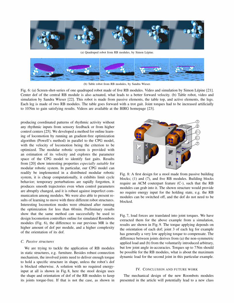
Fig. 6: (a) Screen-shot-series of one quadruped robot made of five RB modules. Video and simulation by Simon Lepine [21].Center dof of the central RB module is also actuated, what leads to a better forward velocity. (b) Table robot, video andsimulation by Sandra Wieser [22]. This robot is made from passive elements, the table top, and active elements, the legs.Each leg is made of two RB modules. The table goes forward with a trot gait. Joint torques had to be increased artificiallyto 10Nm to gain satisfying results. Videos are available at the BIRG homepage [23].
producing coordinated patterns of rhythmic activity withoutany rhythmic inputs from sensory feedback or from highercontrol centers [25]. We developed a method for online learn-ing of locomotion by running an gradient-free optimizationalgorithm (Powell‘s method) in parallel to the CPG model,with the velocity of locomotion being the criterion to beoptimized. The modular robotic system is provided withan estimation of its velocity and explores the parameterspace of the CPG model to identify fast gaits. Resultsfrom [20] show interesting properties especially suitable formodular robotic system. In particular, our CPG model canreadily be implemented in a distributed modular roboticsystem, it is cheap computationally, it exhibits limit cyclebehavior; temporary perturbations are rapidly forgotten, itproduces smooth trajectories even when control parametersare abruptly changed, and it is robust against imperfect com-munication among modules. We were also able to present re-sults of learning to move with three different robot structures.Interesting locomotion modes were obtained after runningthe optimization for less than 60min. Preliminary resultsshow that the same method can successfully be used todesign locomotion controllers online for simulated Roombotsmodules (Fig. 6), the difference to our previous MR is thehigher amount of dof per module, and a higher complexityof the orientation of its dof.
C. Passive structures
We are trying to tackle the application of RB modulesin static structures, e.g. furniture. Besides robust connectionmechanism, the involved joints need to deliver enough torqueto hold a specific structure in shape, unless the robot’s dofis blocked otherwise. A solution with no required energy-input at all is shown in Fig. 8, here the stool design usesthe shape and orientation of dof of the RB modules to keepits joints torque-free. If that is not the case, as shown in
Fig. 8: A first design for a stool made from passive buildingblocks; (1) and (7), and five RB modules. Building blocksrequire an ACM couterpart feature (C-), such that the RBmodules can grab into it. The shown structure would provideno require energy input for the holding state, e.g. the RBmodules can be switched off, and the dof do not need to beblocked.
Fig. 7, load forces are translated into joint torques. We haveextracted them for the above example from a simulation,results are shown in Fig. 9. The torque applying depends onthe orientation of each dof; joint 3 of each leg for examplehas generally a very low applying torque to compensate. Thedifference between joints derives from (a) the non-symmetricapplied load and (b) from the voluntarily introduced arbitrary,but low joint angle in-accuracies. Torques up to 7Nm shouldbe possible for the RB modules, what is about the maximumdynamic load for the second joint in this particular example.
IV. CONCLUSION AND FUTURE WORK
The mechanical design of the new Roombots modulespresented in the article will potentially lead to a new class

1 2 3 4 5 6
0
1
2
3
Joint number
Torq
ue~ M
in[N
m]
Leg 1Leg 2Leg 3Leg 4
Fig. 9: Joint torque values refer to Fig. 7. We conducteda motion model simulation, by placing a 50kg load non-centered on the stool. Motor-joint angles were displaced by5◦-13◦ to include backlash, position errors and elasticity inthe simulation. Motors in the joints were replaced by spring-damper combinations. Above bar plot sorts the joints bylegs, e.g. joint 1 (J1 in Fig. 7) is leg 1, first joint, blue bar.Joint 8 is the second joint of leg 2, red bar plot and so on.Torque values represent applying torque after the stool is inequilibrium state. Dynamic torque values are about twice ashigh as the ones shown.
of versatile and robust Self-reconfiguring Modular Robots. Inaddition to interactive furniture, the Roombots could be usedto generate different types of static and dynamic structures,e.g. a robot arm oscillating a fan, an interactive artisticsculpture, mechanical support for handicapped persons, andtransport of objects.
Current objective is to equip the Roombots modules withreliable electronics and communication hardware (reusingwhat we developed for our previous modular robotic sys-tem [16]). Another future task is to design a user-robotinterface to allow users to guide, control and teach thegroup of modules. We aim at interactions that are high-level and easily learnable by lay people (i.e. general guidancerather than programming), using state-of-the-art PDA-basedinterfaces and tactile interactions with the modules.
V. ACKNOWLEDGMENT
We gratefully acknowledge the technical support of AndreGuignard, Andres Upegui, Elmar Dittrich, Adamo Mad-dalena, Andre Badertscher, Peter Bruhlmeier, and PhilippeVoessler in the design and construction of the robot modules.Furthermore we gratefully acknowledge the contribution ofSimon Lepine and Sandra Wieser. This work was madepossible thanks to financial support from EPFL, the SwissNational Science Foundation and Microsoft Research Cam-bridge.
REFERENCES
[1] S. Jorda, G. Geiger, M. Alonso, and M. Kaltenbrunner, “The reactable:Exploring the synergy between live music performance and tabletoptangible interfaces,” in Proceedings of the first international conferenceon Tangible and Embedded Interaction (TEI07), B. Rouge, Ed.,Louisiana, 2007.
[2] M. Weiser, “The computer for the 21st century,” Scientific American,vol. 265, no. 3, pp. 66–75, September 1991.
[3] R. Azuma, Y. Baillot, R. Behringer, S. Feiner, S. Julier, and B. Mac-Intyre, “Recent advances in augmented reality,” IEEE ComputerGraphics and Applications, vol. 21, no. 6, pp. 34–47, 2001.
[4] N. Streitz, P. Tandler, C. Mueller-Tomfelde, and S. Konomi,“Roomware: Towards the next generation of human-computer interac-tion based on an integrated design of real and virtual worlds,” Human-Computer Interaction in the New Millenium, pp. 553–578, 2001.
[5] S. Murata and H. Kurokawa, “Self-reconfigurable robot: Shape-changing cellular robots can exceed conventional robot flexibility,”IEEE Robotics & Automation Magazine, March 2007.
[6] Y. Terada and S. Murata, “Modular stucture assembly using blackboardpath planning systems,” in International Symposium on Automationand Robotics in Construction 2006, May 2006, pp. 852–857.
[7] V. Zykov, E. Mytilinaios, B. Adams, and H. Lipson, “Self-reproducingmachines,” Nature, vol. 435, no. 7038, pp. 163–164, 2005.
[8] E. H. Ostergaard, K. Kassow, R. Beck, and H. H. Lund, “Design ofthe atron lattice-based self-reconfigurable robot,” Autonomous Robots,vol. 21, no. 2, pp. 165–183, September 2006.
[9] H. Kurokawa, K. Tomita, A. Kamimura, S. K. T. Hasuo, and S. Murata,“Square tile model for self-reconfiguration by m-tran,” in IROS 2007Workshop on Self-Reconfigurable Robots & Systems and Applications,November 2007, pp. 12–15.
[10] D. Rus, Z. Butler, K. Kotay, and M. Vona, “Self-reconfiguring robots,”Communications of the ACM, vol. 45, no. 3, pp. 39–45, 2002.[Online]. Available: citeseer.ist.psu.edu/rus98selfreconfiguring.html
[11] H. C. H. Chiu, M. Rubenstein, and W.-M. Shen, “Multifunctionalsuperbot with rolling track configuration,” in IROS 2007 Workshop onSelf-Reconfigurable Robots & Systems and Applications, November2007, pp. 50–53.
[12] J. Bongard, V. Zykov, and H. Lipson, “Resilient machines throughcontinuous self-modeling,” Science, vol. 314, no. 5802, pp. 1118–1121, 2006. [Online]. Available: 10.1126/science.1133687
[13] “Molecubes for everyone.” [Online]. Available:http://www.molecubes.org
[14] F. Group. [Online]. Available: www.faulhaber-group.com[15] D. Daidie, O. Barbey, A. Guignard, D. Roussy, F. Guenter, A. Ijspeert,
and A. Billard, “The dof-box project: An educational kit for con-figurable robots,” in Proceedings of the 2007 IEEE/ASME Interna-tional Conference on Advanced Intelligent Mechatronics (AIM2007),September 2007.
[16] R. Mockel, A. Sprowitz, J. Maye, and A. J. Ijspeert, “An easy to usebluetooth scatternet protocol for fast data exchange in wireless sensornetworks and autonomous robots,” in IROS2007, 2007.
[17] A. Sproewitz, M. Asadpour, Y. Bourquin, and A. Ijspeert, “An activeconnection mechanism for modular self-reconfigurable robotic systemsbased on physical latching,” in 2008 IEEE International Conferenceon Robotics and Automation, Conference Proceedings, 2008.
[18] “Pololu Robotics and Electronics.” [Online]. Available:http://www.pololu.com
[19] M. Asadpour, A. Sproewitz, A. Billard, P. Dillenbourg, and A. J.Ijspeert, “Graph signature for self-reconfiguration planning,” in IROS2008, 2008, accpted.
[20] A. Sproewitz, R. Moeckel, J. Maye, and A. J. Ijspeert, “Learning tomove in modular robots using central pattern generators and onlineoptimization,” International Journal of Robotics Research, vol. 27,no. 3–4, pp. 423–443, 2008.
[21] S. Lepine, “Locomotion in Modular Robots: YaMoR Host 3 andRoombots,” Master’s thesis, EPFL, Lausanne, 2008.
[22] S. Wieser, “Locomotion in Modular Robotics - Roombot Module,”Master’s thesis, EPFL, Lausanne, 2008.
[23] BIRG. [Online]. Available: birg.epfl.ch[24] S. C. Goldstein, J. D. Campbell, and T. C. Mowry, “Programmable
matter,” Computer, vol. 38, no. 6, pp. 99–101, 2005.[25] F. Delcomyn, “Neural basis for rhythmic behaviour in animals,”
Science, no. 210, pp. 492–498, 1980.