Embed Size (px)
Citation preview
SECTION 18 ROLLING STOCK OUTLINES

ROA MANUAL SCHEDULE OF AMENDMENTS SECTION 18
AMENDMENT NUMBER
PAGES AMENDED
AMENDMENT SUMMARY
DATE ISSUED
This Section of the ROA Manual, as highlighted by red text, is superseded by the following RISSB Australian Standard:
AS 7507 Railway rolling stock - Rolling stock outlines
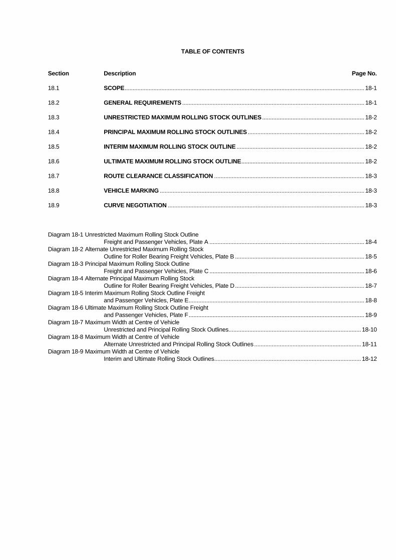
TABLE OF CONTENTS Section Description Page No. 18.1 SCOPE...................................................................................................................................................... 18-1 18.2 GENERAL REQUIREMENTS .................................................................................................................. 18-1 18.3 UNRESTRICTED MAXIMUM ROLLING STOCK OUTLINES ................................................................ 18-2 18.4 PRINCIPAL MAXIMUM ROLLING STOCK OUTLINES ......................................................................... 18-2 18.5 INTERIM MAXIMUM ROLLING STOCK OUTLINE ................................................................................ 18-2 18.6 ULTIMATE MAXIMUM ROLLING STOCK OUTLINE............................................................................. 18-2 18.7 ROUTE CLEARANCE CLASSIFICATION .............................................................................................. 18-3 18.8 VEHICLE MARKING ................................................................................................................................ 18-3 18.9 CURVE NEGOTIATION ........................................................................................................................... 18-3 Diagram 18-1 Unrestricted Maximum Rolling Stock Outline Freight and Passenger Vehicles, Plate A ................................................................................................. 18-4 Diagram 18-2 Alternate Unrestricted Maximum Rolling Stock Outline for Roller Bearing Freight Vehicles, Plate B ................................................................................. 18-5 Diagram 18-3 Principal Maximum Rolling Stock Outline Freight and Passenger Vehicles, Plate C ................................................................................................. 18-6 Diagram 18-4 Alternate Principal Maximum Rolling Stock Outline for Roller Bearing Freight Vehicles, Plate D................................................................................. 18-7 Diagram 18-5 Interim Maximum Rolling Stock Outline Freight and Passenger Vehicles, Plate E.............................................................................................................. 18-8 Diagram 18-6 Ultimate Maximum Rolling Stock Outline Freight and Passenger Vehicles, Plate F.............................................................................................................. 18-9 Diagram 18-7 Maximum Width at Centre of Vehicle Unrestricted and Principal Rolling Stock Outlines................................................................................... 18-10 Diagram 18-8 Maximum Width at Centre of Vehicle Alternate Unrestricted and Principal Rolling Stock Outlines ................................................................... 18-11 Diagram 18-9 Maximum Width at Centre of Vehicle Interim and Ultimate Rolling Stock Outlines............................................................................................ 18-12
18-1 Adopted 18/9/91
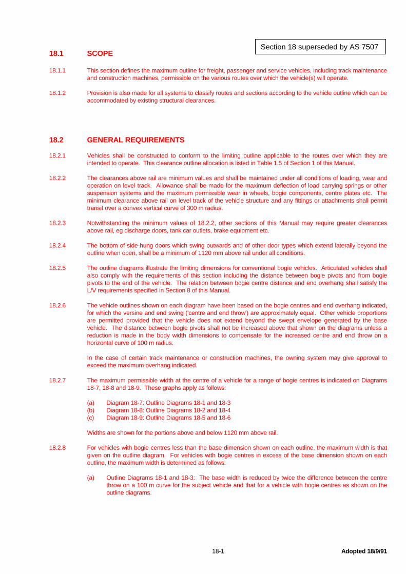
18.1 SCOPE 18.1.1 This section defines the maximum outline for freight, passenger and service vehicles, including track maintenance
and construction machines, permissible on the various routes over which the vehicle(s) will operate. 18.1.2 Provision is also made for all systems to classify routes and sections according to the vehicle outline which can be
accommodated by existing structural clearances. 18.2 GENERAL REQUIREMENTS 18.2.1 Vehicles shall be constructed to conform to the limiting outline applicable to the routes over which they are
intended to operate. This clearance outline allocation is listed in Table 1.5 of Section 1 of this Manual. 18.2.2 The clearances above rail are minimum values and shall be maintained under all conditions of loading, wear and
operation on level track. Allowance shall be made for the maximum deflection of load carrying springs or other suspension systems and the maximum permissible wear in wheels, bogie components, centre plates etc. The minimum clearance above rail on level track of the vehicle structure and any fittings or attachments shall permit transit over a convex vertical curve of 300 m radius.
18.2.3 Notwithstanding the minimum values of 18.2.2, other sections of this Manual may require greater clearances
above rail, eg discharge doors, tank car outlets, brake equipment etc. 18.2.4 The bottom of side-hung doors which swing outwards and of other door types which extend laterally beyond the
outline when open, shall be a minimum of 1120 mm above rail under all conditions. 18.2.5 The outline diagrams illustrate the limiting dimensions for conventional bogie vehicles. Articulated vehicles shall
also comply with the requirements of this section including the distance between bogie pivots and from bogie pivots to the end of the vehicle. The relation between bogie centre distance and end overhang shall satisfy the L/V requirements specified in Section 8 of this Manual.
18.2.6 The vehicle outlines shown on each diagram have been based on the bogie centres and end overhang indicated,
for which the versine and end swing ('centre and end throw') are approximately equal. Other vehicle proportions are permitted provided that the vehicle does not extend beyond the swept envelope generated by the base vehicle. The distance between bogie pivots shall not be increased above that shown on the diagrams unless a reduction is made in the body width dimensions to compensate for the increased centre and end throw on a horizontal curve of 100 m radius.
In the case of certain track maintenance or construction machines, the owning system may give approval to
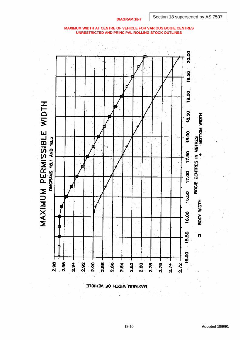
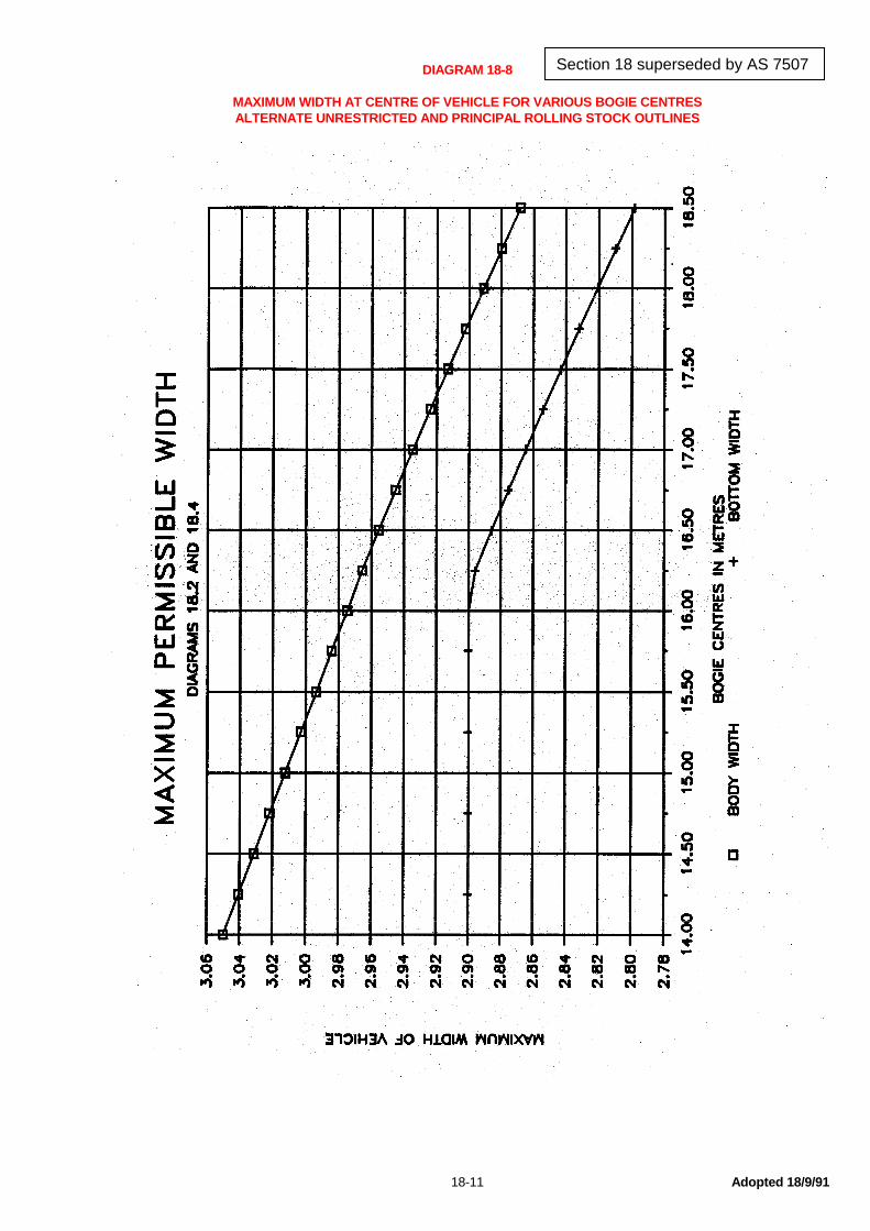
exceed the maximum overhang indicated. 18.2.7 The maximum permissible width at the centre of a vehicle for a range of bogie centres is indicated on Diagrams
18-7, 18-8 and 18-9. These graphs apply as follows: (a) Diagram 18-7: Outline Diagrams 18-1 and 18-3 (b) Diagram 18-8: Outline Diagrams 18-2 and 18-4 (c) Diagram 18-9: Outline Diagrams 18-5 and 18-6 Widths are shown for the portions above and below 1120 mm above rail. 18.2.8 For vehicles with bogie centres less than the base dimension shown on each outline, the maximum width is that
given on the outline diagram. For vehicles with bogie centres in excess of the base dimension shown on each outline, the maximum width is determined as follows:
(a) Outline Diagrams 18-1 and 18-3: The base width is reduced by twice the difference between the centre
throw on a 100 m curve for the subject vehicle and that for a vehicle with bogie centres as shown on the outline diagrams.
Section 18 superseded by AS 7507

18-2 Adopted 18/9/91
(b) Outline Diagrams 18-2 and 18-4: For vehicles with bogie centres greater than 16,150 mm the maximum width is the same as permitted above for Outline Diagrams 18-1 and 18-3. For vehicles with bogie centres between 15,000 mm and 16,150 mm the body width is reduced proportionately from 3,050 to 2,970 mm, and the width below 1,120 above rail remains as 2,900 mm.
(c) Outline Diagrams 18-5 and 18-6: The maximum width is determined as in (a) above. 18.2.9 The width at the end of a vehicle may also require a reduction to ensure the end throw remains within the swept
envelope of the base vehicle, depending on the overhang. 18.2.10 The vehicle width may be increased proportionately between the vehicle centre and the bogie centre.
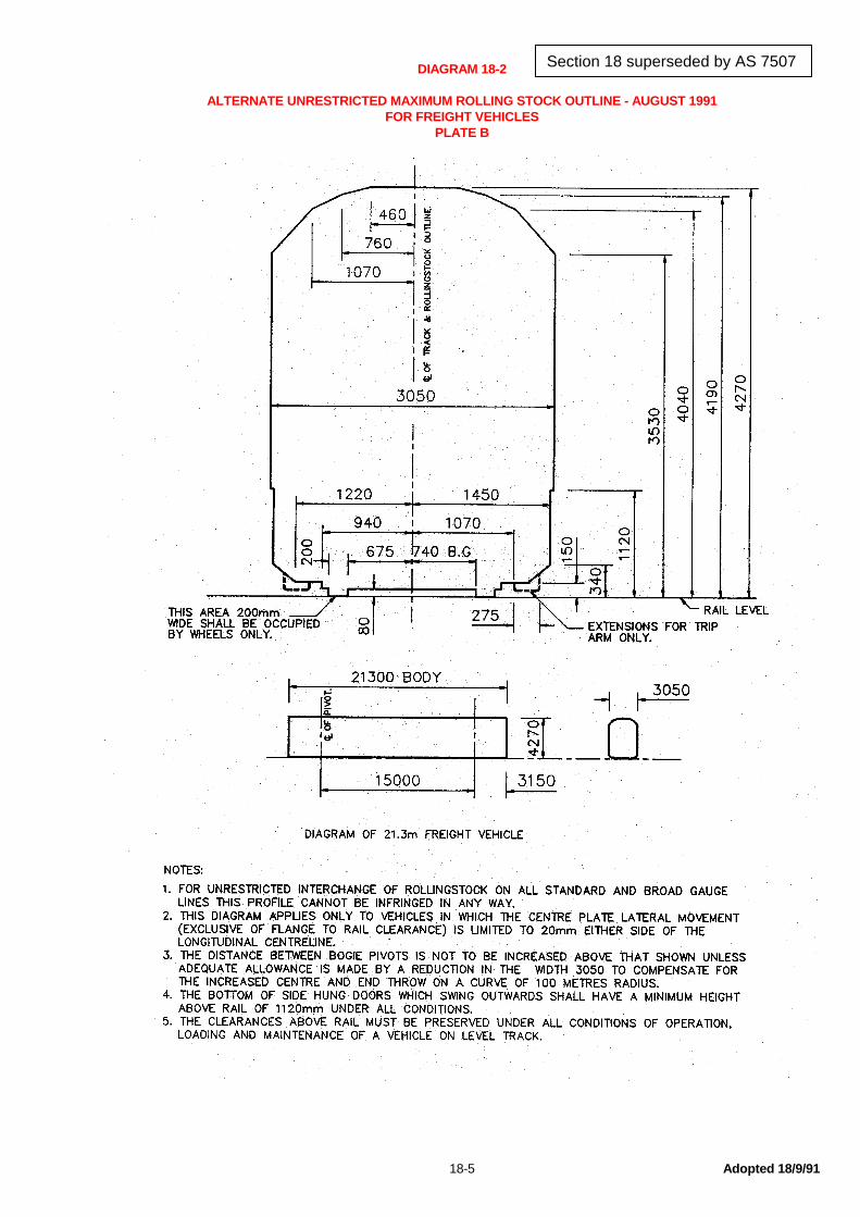
18.3 UNRESTRICTED MAXIMUM ROLLING STOCK OUTLINES 18.3.1 Diagrams 18.1 and 18.2 illustrate the limiting outline for vehicles intended for unrestricted intersystem operation
on all standard and broad gauge lines, including electrified lines. 18.3.2 Diagram 18.1 shows a conventional vehicle 22850 mm over end sills and 16150 mm between bogie pivots, with
the maximum body width of 2970 mm. Diagram 18.2 shows an alternate outline, 21300 mm over end sills, 15000 mm between bogie pivots and a maximum body width of 3050 mm.
18.4 PRINCIPAL MAXIMUM ROLLING STOCK OUTLINES 18.4.1 Diagrams 18.3 and 18.4 illustrate the limiting outlines for vehicles intended for intersystem operation on all
standard gauge lines and broad gauge lines outside Victoria, including electrified lines. 18.4.2 The area outside the wheels, 80 mm above rail and 1130 mm from the vehicle centre line shall be occupied by
bogie components only. 18.4.3 The area outside the wheels, 80 mm above rail and 1345 mm from the vehicle centre line, shall be occupied by
trip-arms only.
18.5 INTERIM MAXIMUM ROLLING STOCK OUTLINE 18.5.1 Vehicles built to the limiting outline shown on Diagram 18.5 are restricted to operation on routes for which transit
clearance has been authorised outside electrified areas.
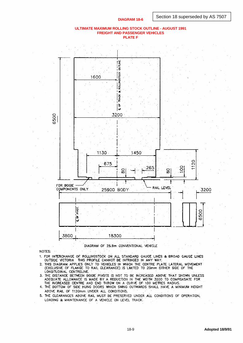
18.6 ULTIMATE MAXIMUM ROLLING STOCK OUTLINE 18.6.1 Diagram 18.6 illustrates the Ultimate Maximum Rolling Stock Outline for intersystem operation. 18.6.2 This diagram is used to generate the Ultimate Minimum Structure Gauge (Section 1), applicable to all new and
substantially modified structures outside electrified areas. 18.6.3 Vehicles conforming to this outline are restricted to operation on routes conforming to the Ultimate Minimum
Structure Gauge or for which transit clearance has been authorised.
Section 18 superseded by AS 7507
18-3 Adopted 18/9/91
18.7 ROUTE CLEARANCE CLASSIFICATION 18.7.1 Each rail system shall classify its routes, sections of routes or lines according to the vehicle outlines which can be
accepted for transit with the structural clearance available. 18.7.2 Route classification shall be as follows: (a) Class A : Will accept vehicles conforming to outline diagrams 18.1 and 18.2 (b) Class C : Will accept vehicles conforming to outline diagrams 18.3 and 18.4 (c) Class E : Will accept vehicles conforming to outline diagram 18.5 (d) Class F : Will accept vehicles conforming to outline diagram 18.6 18.7.3 Route classifications are listed in Table 1.5 of Section 1 of this Manual. Flat, well and open cars are defined by
the maximum width; vehicle height is not generally a factor. Transit clearance for these types of vehicles will be influenced by the dimensions of the loading. Systems may impose general or specific loading outlines which differ from the vehicle outlines given in this Section.
18.8 VEHICLE MARKING 18.8.1 Each vehicle shall be marked with the outline to which it conforms. 18.8.2 Details of these markings and their location is given in Section 22 of this Manual.
18.9 CURVE NEGOTIATION In addition to the dimensional outlines specified by this Section, vehicles shall also comply with the requirements
for negotiating curves specified in Section 8.2.15 of this Manual.
Section 18 superseded by AS 7507

18-4 Adopted 18/9/91
DIAGRAM 18-1 UNRESTRICTED MAXIMUM ROLLING STOCK OUTLINE - AUGUST 1991 FREIGHT AND PASSENGER VEHICLES PLATE A
Section 18 superseded by AS 7507
18-5 Adopted 18/9/91
DIAGRAM 18-2 ALTERNATE UNRESTRICTED MAXIMUM ROLLING STOCK OUTLINE - AUGUST 1991 FOR FREIGHT VEHICLES PLATE B
Section 18 superseded by AS 7507

18-6 Adopted 18/9/91
DIAGRAM 18-3 PRINCIPAL MAXIMUM ROLLING STOCK OUTLINE - AUGUST 1991 FREIGHT AND PASSENGER VEHICLES PLATE C
Section 18 superseded by AS 7507

18-7 Adopted 18/9/91
DIAGRAM 18-4 ALTERNATE PRINCIPAL MAXIMUM ROLLING STOCK OUTLINE - AUGUST 1991 FOR FREIGHT VEHICLES PLATE D
Section 18 superseded by AS 7507

18-8 Adopted 18/9/91
DIAGRAM 18-5 INTERIM MAXIMUM ROLLING STOCK OUTLINE - AUGUST 1991 FREIGHT AND PASSENGER VEHICLES PLATE E
Section 18 superseded by AS 7507
18-9 Adopted 18/9/91
DIAGRAM 18-6 ULTIMATE MAXIMUM ROLLING STOCK OUTLINE - AUGUST 1991 FREIGHT AND PASSENGER VEHICLES PLATE F
Section 18 superseded by AS 7507
18-10 Adopted 18/9/91
DIAGRAM 18-7 MAXIMUM WIDTH AT CENTRE OF VEHICLE FOR VARIOUS BOGIE CENTRES UNRESTRICTED AND PRINCIPAL ROLLING STOCK OUTLINES
Section 18 superseded by AS 7507
18-11 Adopted 18/9/91
DIAGRAM 18-8 MAXIMUM WIDTH AT CENTRE OF VEHICLE FOR VARIOUS BOGIE CENTRES ALTERNATE UNRESTRICTED AND PRINCIPAL ROLLING STOCK OUTLINES
Section 18 superseded by AS 7507

18-12 Adopted 18/9/91
DIAGRAM 18-9 MAXIMUM WIDTH AT CENTRE OF VEHICLE FOR VARIOUS BOGIE CENTRES INTERIM AND ULTIMATE ROLLING STOCK OUTLINES
Section 18 superseded by AS 7507