Embed Size (px)
Citation preview

A
aKut
ca
fitb©
K
1
tssmpsa
ncb
0d
Electrochimica Acta 52 (2007) 7651–7659
Role of intermetallic phases in localized corrosion of AA5083
Kiryl A. Yasakau a, Mikhail L. Zheludkevich a,∗,Sviatlana V. Lamaka a, Mario G.S. Ferreira a,b
a University of Aveiro, CICECO, Department of Ceramics and Glass Engineering, 3810-193 Aveiro, Portugalb Instituto Superior Tecnico, ICEMS, Department of Chemical Engineering, Av. Rovisco Pais, 1049-001 Lisboa, Portugal
Received 17 July 2006; received in revised form 26 October 2006; accepted 17 December 2006Available online 25 January 2007
bstract
The presence of intermetallic inclusions very often plays a crucial role for the susceptibility of different aluminium alloys to localized corrosionttack. The intimate details of localized corrosion of 5083 aluminium alloy have been studied in the present work. Local techniques such as scanningelvin probe force microscopy, in situ atomic force microscopy, scanning electron microscopy coupled with energy dispersive spectroscopy weresed to investigate the mechanisms and the kinetics of localized corrosion attack. The importance of iron-rich and Mg2Si intermetallic phases inhe initiation of corrosion processes is demonstrated in the paper.
The Mg2Si phase has a potential lower relatively to the matrix. Moreover, the high reactivity of magnesium leads to the dissolution andonsequently to the fast dealloying of these intermetallics. However, hydroxide (Mg(OH)2 and SiO2·nH2O) deposits formed during corrosion acts an additional diffusion barrier hindering the deep propagation of pits.
The iron containing intermetallics have the potential higher with respect to the aluminum matrix playing the role of effective cathodic centersor oxygen reduction causing anodic polarization and pitting in the surrounding alloy matrix. Dealloying of such intermetallics with subsequent
ron enrichment was also revealed. Pitting initiation seems to be statistical and independent of the composition of Fe-rich intermetallics. However,he active growth of the pits prevents initiation of localized corrosion attack in nearby sites. A new pit can start to grow only when a neighbor oneecomes passivated.2007 Elsevier Ltd. All rights reserved.
py; In
Tac
hrctttA
eywords: AA5083; Corrosion; Pitting; Scanning Kelvin probe force microsco
. Introduction
The 5083 aluminum alloy is widely used for many applica-ions in automotive, marine, construction industry due to hightrength to weight ratio, reasonable corrosion resistance anduperelasticity [1,2]. The presence of different kind of inter-etallic precipitates in the alloy matrix improves mechanical
roperties, but leads to higher susceptibility to localized corro-ion. The main types of intermetallic inclusions in the 5083 alloyre iron-rich and magnesium-rich intermetallics [3–5].
Previous works show that the Al6(Fe, Mn) phase has more
oble potential relatively to aluminium [6] and, thereby, theathodic reactions have being taking place there are responsi-le for pitting formation in the surrounding alloy matrix [7].∗ Corresponding author. Tel.: +351 234 378146; fax: +351 234 425300.E-mail address: [email protected] (M.L. Zheludkevich).
staa
pb
013-4686/$ – see front matter © 2007 Elsevier Ltd. All rights reserved.oi:10.1016/j.electacta.2006.12.072
termetallic phases
he cathodic reaction of oxygen reduction produces hydroxylnions, which help to break the oxide layer near the Fe-ontaining particles promoting pitting formation [7,8].
On the other hand, the Mg–Si phase (Mg2Si) is reported toave similar values of corrosion potential relatively to the sur-ounding aluminium matrix [9] or a lower corrosion potentialompared to the aluminum matrix [10]. In case of moderate heatreatment, �-phase (Al3Mg2) precipitates can be formed alonghe grain boundaries [11,12]. The �-phase has a corrosion poten-ial of about −1.29 V (SCE) [13] compared to −0.73 V (SCE) ofA5083, which implies increased anodic activity towards dis-
olution in a corrosive environment. The activity of that phase ishe main reason for stress corrosion cracking (SCC) occurringt the grain boundaries of aluminum alloys with precipitates of
ctive phases formed during heat treatment [14].Different local techniques have been used recently torovide supplementary information to the results obtainedy classical electrochemical methods contributing to deeper

7 himic
upctocMbss
ipsaoVlb
cofcmwcscc
2
stsra
0ii
tesIn
sitsdtoacetttmw
dmc
3
3
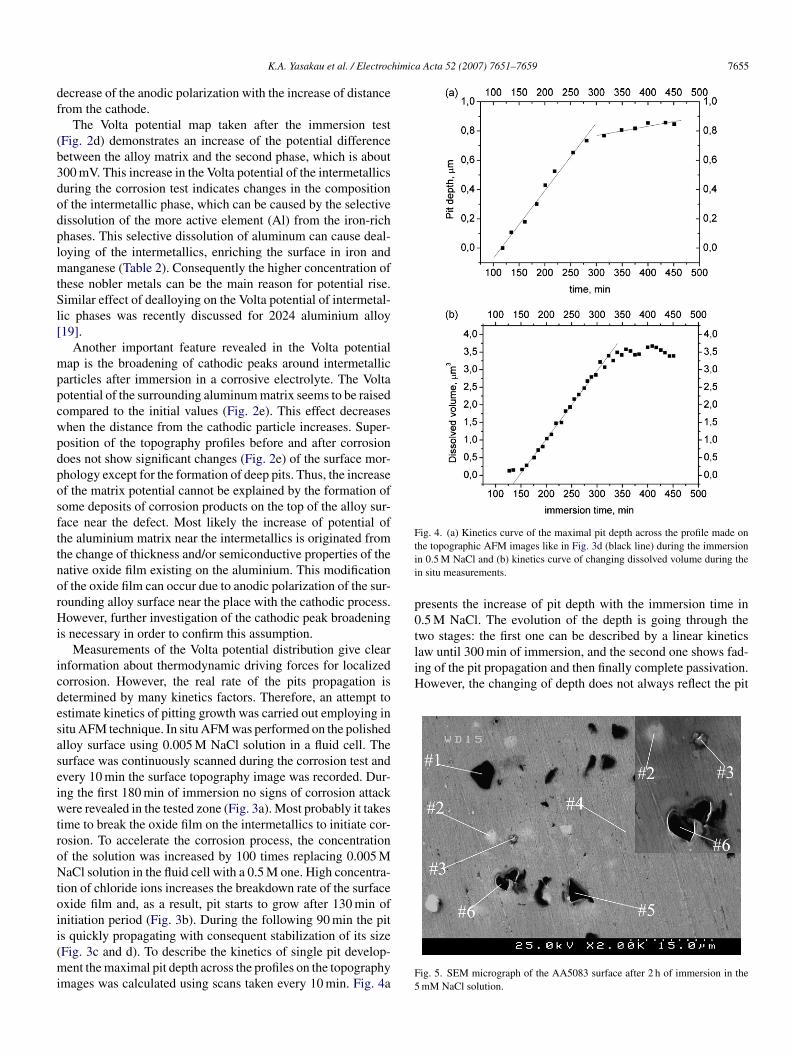
tis represented by several phases such as Al–(Fe, Mn, Cr, Si) andAl6(Fe, Mn). SEM micrograph of the AA5083 surface after 2 hof immersion in the 0.005 M NaCl solution is shown in Fig. 1.The different zones in this micrograph were analyzed by EDS
TC
C
652 K.A. Yasakau et al. / Electroc
nderstanding of corrosion mechanisms. Scanning Kelvinrobe force microscopy (SKPFM) was found to be useful inorrosion applications since the Volta potential measured byhe Kelvin probe can be correlated with the work functionf the surface. Places with higher work functions are noblerompared to those ones with lower work functions [15–17].oreover, the measured Volta potential difference in air can
e correlated with the OCP measured in liquid [15,16]. Thus,canning Kelvin probe force microscopy can be applied totudy the electrochemical behavior of different metals [17–19].
The electrochemical character of the intermetallic inclusionsn AA5083 was never studied before by means of the Kelvinrobe technique. However, some intermetallic inclusions wereuccessfully investigated in the case of AA2024 and AA7075lloys. The Mg–Si-containing phase, which is similar to thatf AA5083, was characterized by SKPFM technique [20]. Theolta potential of such Mg2Si particles is about 100–180 mV
ower compared to the aluminum matrix, indicating anodicehavior of such compounds.
In this work, the authors present a study about the localizedorrosion activity of AA5083 aiming at a better understandingf the mechanisms of pitting formation. The main attention isocused on the role of the most active intermetallic phases, whichan be either cathodic or anodic with respect to the aluminumatrix. The different localized techniques are employed in thisork to give deeper mechanistic understanding of the localized
orrosion attack. Scanning Kelvin probe force microscopy, initu atomic force microscopy and scanning electron microscopyoupled with energy dispersive spectroscopy were used as mainomplimentary methods in this paper.
. Experimental
The 5083 aluminum alloy with elemental composition pre-ented in Table 1 was used in this work. The specimens havinghickness of about 1 mm were polished with 1200 grid SiCand paper in water, finished with non-aqueous diamond slur-ies down to 2 �m and then cleaned by ultrasound in acetonend ethanol.
Polished aluminum samples were immersed in 0.5 and.005 M NaCl solutions for different periods of time. Aftermmersion the samples were rinsed with distilled water and driedn a desiccator.
A commercial AFM Digital Instruments NanoScope III sys-em with ExtenderTM Electronic Module was used to study the
volution of the aluminum surface both ex situ after immer-ion in corrosion media and in situ in the corrosive electrolyte.n situ images of the topography were acquired using siliconitride probes in contact with the sample surface.FN
able 1omposition (wt%) of the aluminum alloy 5083
Element
Cu Cr Fe Mg M
oncentration 0.1 0.05–0.25 0.4 4.0–4.9 0
a Acta 52 (2007) 7651–7659
Scanning Kelvin probe force microscopy was performed totudy the evolution of the Volta potential of the alloy surface aftermmersion in the NaCl electrolyte. For SKPFM measurementshe AFM was operating in the interleave mode with two passcans. The first scan acquired topography of the surface, whileuring the second scan the tip was lifted up from the surfaceo a distance of 100 nm, the piezoelectric actuator was switchedff and an ac voltage of 1000 mV was applied between the tipnd sample to cause electrostatically induced oscillation of theantilever. Using the nulling technique the Volta potential differ-nce between the sample surface and the tip was measured overhe whole surface to obtain the Volta potential map. Values ofhe Volta potential were normalized and represent Volta poten-ial differences of cathodic and anodic places with respect to the
atrix. For all SKPFM measurements silicon probes coveredith Cr–Pt layers were used.Scanning electron microscopy (SEM) coupled with energy
ispersive spectroscopy (EDS) was used to reveal theicrostructure of the surface and the changes in the elemental
omposition.
. Results
.1. Iron-rich intermetallic phases
The main type of intermetallic inclusions that were found inhe case of the 5083 aluminum alloy is the iron-rich phase, which
ig. 1. SEM micrograph of the AA5083 surface after 2 h of immersion in 5 mMaCl solution.
n Si Ti Zn Other Al
.4–1.0 0.4 0.15 0.25 0.15 Balanced
K.A. Yasakau et al. / Electrochimica Acta 52 (2007) 7651–7659 7653
Table 2Relative proportions of the elements (at%) in places indicated on Fig. 1
Element ratio #1 #2 #3 #4 #5 #6 Al6(FeMnCrSi) untreateed Al6(FeMn) untreateed
Mn/Al 0.054 0.044 0.015 – – – 0.045 0.025Fe/Al 0.148 0.067 0.035 – – – 0.075 0.045S .015M .077C
(izogds
aer
Fs
i/Al 0.046 0.035 – 0.054 0g/Al 0.029 0.041 0.066 0.075 0r/Al 0.004 0.003 – – –
Table 2) in order to estimate the type of intermetallics existingn these locations. The relative elemental ratios in the differentones clearly demonstrate that large particles in the central part
f the micrograph (#1, #2, #3) are enriched in iron and man-anese compared to the aluminum matrix (#6). There are twoifferent sorts of intermetallics, one contains Si and Cr and aecond one is free of these two elements. The corrosion attack isiwfo
ig. 2. AFM image and Volta potential map of region shown in Fig. 1: (a and b) beforolution; (e) height and Volta potential profiles on the corresponding surface.
– 0.0350.074 0.047 0.058– 0.003 –
lready clearly visible near the iron-rich intermetallic particlesven after short immersion period in spite of the reasonable cor-osion resistance of the 5083 alloy. The main corrosion attack
s focused in the alloy matrix surrounding these intermetallicsith the formation of a pit. The statistical analysis of many pitsormed near the iron-rich phases does not show any dependencef the susceptibility to the localized attack on the presence of
e immersion, respectively, and (c and d) after immersion for 2 h in 5 mM NaCl

7 himic
Sis
iofmp
tbtw
tmusTpthstp
diclaoc
tTisivao
O
Tt
Fii
654 K.A. Yasakau et al. / Electroc
i and Cr in the intermetallic phase. Both types of iron-richntermetallics Al–(Fe, Mn, Cr, Si) and Al6(Fe, Mn) seem to beimilarly corroded.
The composition of the intermetallics does not give enoughnformation on the electrochemical character of this phase andn the details of the mechanism of corrosion attack. There-ore, AFM-based localized techniques were employed to obtainechanistic understanding of the role of different intermetallic
hases in AA5083.SKPFM technique was successfully used in the characteriza-
ion of the corrosion susceptibility of different alloys as it haveeen reported in previous investigations [15,16,18]. In this work,he potential distribution along the surface of polished AA5083as measured before and after immersion in chloride solution.Fig. 2 presents topography and potential maps obtained in
he places of iron-rich intermetallics depicted in the electronicrograph (Fig. 1). The measurements were carried out on the
ncorroded polished substrate (a and b) and on the AA5083urface immersed for 2 h in 0.005 M NaCl solution (c and d).he initial alloy surface demonstrates typical topography of theolished metal (Fig. 2a). Slightly defined hills are visible inhe places of the intermetallics most probably due to the higher
ardness of this phase in comparison to the alloy matrix. Themall hole in the zone of the intermetallic can appear due tohe removal of an intermetallic piece from the matrix during theolishing procedure. The Volta potential map depicted in Fig. 2bA
Tm[
ig. 3. Topography evolution of AA5083 surface during in situ AFM measurementsn 0.005 M NaCl, (b) pit initiation after 130 min of immersion in 0.5 M NaCl, (c) pit gn 0.5 M NaCl.
a Acta 52 (2007) 7651–7659
emonstrates well-defined maxima in the zones of the iron-richntermetallics. The shape of the potential maxima precisely repli-ates the shape of the iron-containing phase revealed by SEMeading to the conclusion that the iron-containing intermetallicsre nobler than the alloy matrix from the electrochemical pointf view. Thus, they can play the role of local cathodes in theorrosion process.
Immersion of the polished alloy sample in the chloride solu-ion for 2 h causes drastic changes of the surface topography.he deep pitting-like crevices are formed on the boundary of the
ntermetallic phases. The AFM image in Fig. 2c clearly demon-trates dissolution of the alloy matrix surrounding the cathodicntermetallics. This severe localized attack occurs due to gal-anic coupling between the nobler iron-rich phase and the morective aluminum alloy matrix. In this case, the cathodic reactionf oxygen reduction occurs on the intermetallic surface:
2 + 2H2O + 4e− → 4OH−. (1)
he main anodic process which accompanies the cathodic reac-ion is dissolution of the aluminum matrix:
3+ −
l → Al + 3e . (2)he dissolution of aluminum occurs adjacent to the inter-etallics because of the weaker native oxide film in this zone
21]. An effect can also appear due to IR-drop resulting in
showing pit initiation and growth: (a) topography after 180 min of immersionrowth after 220 min in 0.5 M NaCl and (d) image after immersion for 450 min
himica Acta 52 (2007) 7651–7659 7655
df
(b3dodplmtSl[
mppcwpdposfttnorHi
icdesaseiwtroNtoii(mi
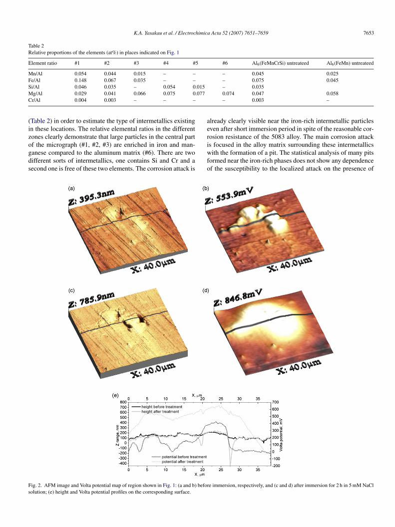
Fig. 4. (a) Kinetics curve of the maximal pit depth across the profile made ontii
p0two stages: the first one can be described by a linear kineticslaw until 300 min of immersion, and the second one shows fad-ing of the pit propagation and then finally complete passivation.However, the changing of depth does not always reflect the pit
K.A. Yasakau et al. / Electroc
ecrease of the anodic polarization with the increase of distancerom the cathode.
The Volta potential map taken after the immersion testFig. 2d) demonstrates an increase of the potential differenceetween the alloy matrix and the second phase, which is about00 mV. This increase in the Volta potential of the intermetallicsuring the corrosion test indicates changes in the compositionf the intermetallic phase, which can be caused by the selectiveissolution of the more active element (Al) from the iron-richhases. This selective dissolution of aluminum can cause deal-oying of the intermetallics, enriching the surface in iron andanganese (Table 2). Consequently the higher concentration of
hese nobler metals can be the main reason for potential rise.imilar effect of dealloying on the Volta potential of intermetal-
ic phases was recently discussed for 2024 aluminium alloy19].
Another important feature revealed in the Volta potentialap is the broadening of cathodic peaks around intermetallic
articles after immersion in a corrosive electrolyte. The Voltaotential of the surrounding aluminum matrix seems to be raisedompared to the initial values (Fig. 2e). This effect decreaseshen the distance from the cathodic particle increases. Super-osition of the topography profiles before and after corrosionoes not show significant changes (Fig. 2e) of the surface mor-hology except for the formation of deep pits. Thus, the increasef the matrix potential cannot be explained by the formation ofome deposits of corrosion products on the top of the alloy sur-ace near the defect. Most likely the increase of potential ofhe aluminium matrix near the intermetallics is originated fromhe change of thickness and/or semiconductive properties of theative oxide film existing on the aluminium. This modificationf the oxide film can occur due to anodic polarization of the sur-ounding alloy surface near the place with the cathodic process.owever, further investigation of the cathodic peak broadening
s necessary in order to confirm this assumption.Measurements of the Volta potential distribution give clear
nformation about thermodynamic driving forces for localizedorrosion. However, the real rate of the pits propagation isetermined by many kinetics factors. Therefore, an attempt tostimate kinetics of pitting growth was carried out employing initu AFM technique. In situ AFM was performed on the polishedlloy surface using 0.005 M NaCl solution in a fluid cell. Theurface was continuously scanned during the corrosion test andvery 10 min the surface topography image was recorded. Dur-ng the first 180 min of immersion no signs of corrosion attackere revealed in the tested zone (Fig. 3a). Most probably it takes
ime to break the oxide film on the intermetallics to initiate cor-osion. To accelerate the corrosion process, the concentrationf the solution was increased by 100 times replacing 0.005 MaCl solution in the fluid cell with a 0.5 M one. High concentra-
ion of chloride ions increases the breakdown rate of the surfacexide film and, as a result, pit starts to grow after 130 min ofnitiation period (Fig. 3b). During the following 90 min the pit
s quickly propagating with consequent stabilization of its sizeFig. 3c and d). To describe the kinetics of single pit develop-ent the maximal pit depth across the profiles on the topographymages was calculated using scans taken every 10 min. Fig. 4aF5
he topographic AFM images like in Fig. 3d (black line) during the immersionn 0.5 M NaCl and (b) kinetics curve of changing dissolved volume during then situ measurements.
resents the increase of pit depth with the immersion time in.5 M NaCl. The evolution of the depth is going through the
ig. 5. SEM micrograph of the AA5083 surface after 2 h of immersion in themM NaCl solution.
7656 K.A. Yasakau et al. / Electrochimica Acta 52 (2007) 7651–7659
Table 3Relative proportions of the elements (at%) in places indicated on Fig. 5
Element ratio #1 #2 #3 #4 #5 #6 Mg2Si untreated
Mn/Al – 0.025 0.014 – – – –Fe/Al – 0.036 0.012 – – – –Si/Al 0.329 0.028 0.011 – 0.272 0.246 0.586MC
gTtieTictseiIpzoDaab
Auoppl
3
Abaipc
Fr
g/Al 0.274 0.063 0.072r/Al – 0.002 0.001
rowth kinetics especially when the pit is not hemispherical.opography analysis let us calculate the dissolved volume of
he aluminum matrix surrounding the iron-rich phase during themmersion in 0.5 M NaCl. The kinetics curve describing thevolution of the dissolved volume with time is shown in Fig. 4b.he initial induction period is well defined at the beginning of
mmersion and is about 150 min. After that pits are growing withonstant rate which can be described by a linear kinetic law upo 300 min of immersion (Fig. 4b). The development of pittinglows down later with consequent stopping of growth. When thexpansion of the pit is stopped another pit starts at the neighborron-rich intermetallic as pointed by the black arrow in Fig. 3d.t seems that the active development of one pit leads to anodicolarization of the surrounding region shifting it to a passiveone. This assumption is in good agreement with broadeningf the cathodic peaks near the corroded iron-rich intermetallics.
ecrease of the pitting activity leads to decrease of polarizationllowing activation of new pit in the neighborhood. This modelgrees with the results obtained by Battocchi et al. on wire-eam electrode (WBE) used to simulate localized corrosion of
tbss
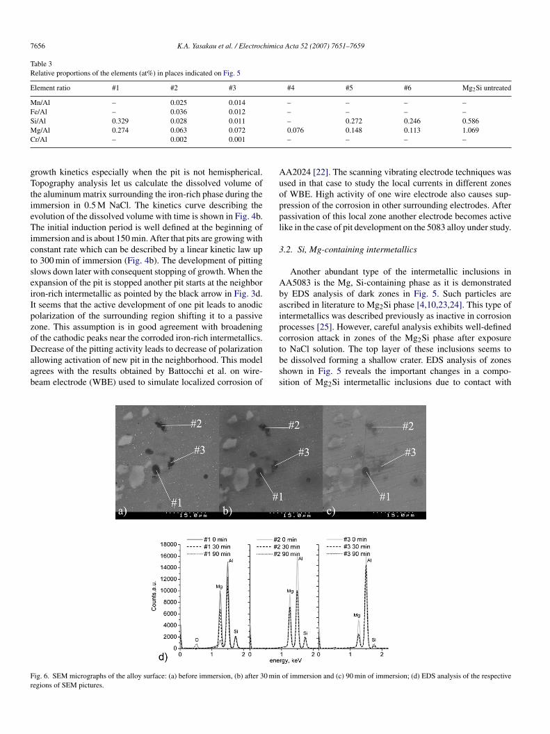
ig. 6. SEM micrographs of the alloy surface: (a) before immersion, (b) after 30 minegions of SEM pictures.
0.076 0.148 0.113 1.069– – – –
A2024 [22]. The scanning vibrating electrode techniques wassed in that case to study the local currents in different zonesf WBE. High activity of one wire electrode also causes sup-ression of the corrosion in other surrounding electrodes. Afterassivation of this local zone another electrode becomes activeike in the case of pit development on the 5083 alloy under study.
.2. Si, Mg-containing intermetallics
Another abundant type of the intermetallic inclusions inA5083 is the Mg, Si-containing phase as it is demonstratedy EDS analysis of dark zones in Fig. 5. Such particles arescribed in literature to Mg2Si phase [4,10,23,24]. This type ofntermetallics was described previously as inactive in corrosionrocesses [25]. However, careful analysis exhibits well-definedorrosion attack in zones of the Mg2Si phase after exposure
o NaCl solution. The top layer of these inclusions seems toe dissolved forming a shallow crater. EDS analysis of zoneshown in Fig. 5 reveals the important changes in a compo-ition of Mg2Si intermetallic inclusions due to contact withof immersion and (c) 90 min of immersion; (d) EDS analysis of the respective

himic
epM2eshzclipii(ta
acosanao
psi(
Fs
K.A. Yasakau et al. / Electroc
lectrolyte. Table 3 summarizes the information on relative com-ositions estimated in different zones depicted in Fig. 5. Theg/Si ratio in the zone of the untreated intermetallic is close to
:1 (Table 3). Only 2 h of immersion in diluted 0.005 M NaCllectrolyte causes drastic change of the intermetallics compo-ition. The EDS analysis taken in the different places of Fig. 5ave shown depletion of magnesium in the Mg2Si phase (darkones #1, #5, #6). Decrease in concentration of magnesium isaused by the dealloying of Mg2Si particles. To estimate the evo-ution of the magnesium content in intermetallics, step-by-stepmmersion of the AA5083 in the 0.005 M NaCl solution waserformed. Preliminarily EDS analysis was taken in differentntermetallic inclusions (Table 3). Then aluminum sample was
mmersed for 30 min in solution, dried and evaluated by EDSFig. 6d). This procedure was repeated for different immersionimes. Fig. 6 presents the SEM images of the alloy surface beforend after different times of immersion. No significant changespVli
ig. 7. AFM image and Volta potential map of region showed in Fig. 5: (a and b) befoolution; (e) height and Volta potential profiles on the corresponding surface.
a Acta 52 (2007) 7651–7659 7657
re visible on the surface by SEM after 30 min of immersion. Inontrast to this, EDS analysis shows slow decrease in intensityf the magnesium peak for all zones after 30 min of immer-ion. Zone #1 (Fig. 6d) shows further decrease in intensity evenfter 90 min of immersion compared to other places that areot active. Decrease of magnesium content is accompanied byppearance of an oxygen peak resulting from formation of oxider hydroxide compounds.
Volta potential maps were also obtained in a zone with Mg2Sihases as depicted in Fig. 7. The potential distribution was mea-ured on the polished substrate prior and after 2 h of immersionn 0.005 M chloride electrolyte. The initial Volta potential mapFig. 7b) of the unexposed surface reveals zones with lower
otential in the places of Mg2Si intermetallics. The averageolta potential of these intermetallics is approximately 80 mVower than the matrix suggesting an anodic character of thesentermetallics with respect to the alloy matrix. A small anodic
re immersion, respectively, and (c and d) after immersion for 2 h in 5 mM NaCl
7 himic
piaaieTnaVmdb4ioIionlmp(caii
tomtsmmstficdip
zNmpcdio2M
Fr
658 K.A. Yasakau et al. / Electroc
article was shown before in Fig. 1 (#5) and the correspond-ng Volta potential map (Fig. 2b, black zone) also reveals thenodic character of it. The situation changes drastically whenlloy is immersed in NaCl solution. Shallow holes are formedn the places of several intermetallics in the alloy surface. How-ver, not all the intermetallics have tendency to be dissolved.he inclusion marked with a white arrow #1 seems to be almostot changed after the immersion test, while one pointed withblack arrow #5 demonstrates formation of a 200 nm hole.
ery important changes were also revealed on the Volta potentialaps. The Mg2Si intermetallic marked with black arrow, which
emonstrated anodic behavior before immersion, has a cathodicehavior after immersion with Volta potential difference about20 mV more than aluminum matrix (Fig. 7d and e). Anotherntermetallic marked with white arrow also demonstrates raisef potential although 300 mV less than in the previous case.ncrease of Volta potential during immersion can be explainedn terms of dealloying of the intermetallic phase as in the casef the cathodic iron-rich intermetallic phase. Very active mag-esium can be selectively dissolved from Mg2Si intermetallicseaving Si-enriched remnants as it was demonstrated by EDS
easurements. The work function in vacuum conditions forure Si (4.85 eV) is higher than that for Mg (3.66 eV) and Al4.19 eV) [26]. Thus, the enrichment of intermetallic in siliconould lead to an increase of the measured Volta potential. This
ssumption can also be supported with the EDS results presentedn Table 3. Ratio of Mg to Si in the zone of the black arrows almost twice lower than that of the white arrow explainingadd
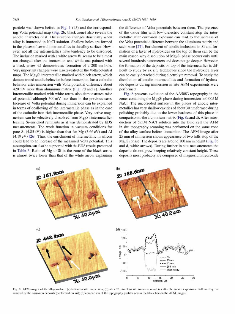
ig. 8. AFM images of the alloy surface: (a) before in situ immersion, (b) after 25emoval of the corrosion deposits (performed on air); (d) comparison of the topograp
a Acta 52 (2007) 7651–7659
he difference of Volta potentials between them. The presencef the oxide film with low dielectric constant atop the inter-etallic after corrosion exposure can lead to the increase of
he Volta potential difference between the aluminum matrix anduch zone [27]. Enrichment of anodic inclusions in Si and for-ation of a layer of hydroxides on the top of them can be theain reason why dissolution of Mg2Si phase occurs only until
everal hundreds nanometers and does not go deeper. However,he formation of the deposits on top of the intermetallics is dif-cult to study by ex situ techniques since the hydroxide layeran be easily detached during electrolyte removal. To study theissolution of anodic intermetallics and formation of hydrox-de deposits during immersion in situ AFM experiments wereerformed.
Fig. 8 presents evolution of the AA5083 topography in theones containing the Mg2Si phase during immersion in 0.005 MaCl. The uncorroded surface in the places of anodic inter-etallics has very shallow cavities of about 30 nm formed during
olishing probably due to the lower hardness of this phase inomparison to the aluminium matrix (Fig. 8a and d). After intro-uction of 5 mM NaCl solution into the fluid cell the AFMn situ topography scanning was performed on the same zonef the alloy surface before immersion. The AFM image after5 min of immersion shows appearance of two hills atop of theg Si phase. The deposits are around 100 nm in height (Fig. 8b
2nd d, white arrows). During further in situ measurements theeposits do not grow keeping relatively constant height. Theseeposits most probably are composed of magnesium hydroxide
min of in situ immersion and (c) after the in situ experiment followed by thehy profiles across the black line on the AFM images.

himic
tSsfwddhfif
iisbi
M
Shm
S
si
M
potp
4
isSdd
asati
sp
pttmdte
R
[[
[
[
[
[[[
[
[
[[[
[[
K.A. Yasakau et al. / Electroc
hat was formed due to selective dissolution of magnesium andiO2·nH2O. Two other zones do not demonstrate formation ofuch high deposits; however, the surface is also elevated at leastor 50 nm. The deposits formed in the zones of the white arrowsere removed leaving 100 nm deep holes demonstrating partialissolution of Mg2Si intermetallics (Fig. 8c and d). However,issolution does not occur too deep. Thus, the formation of theydroxide deposits on the top of Mg2Si is the most likely reasonor relatively low corrosion activity of this phase. The hydrox-de deposits can form an additional diffusion barrier hinderingurther dissolution of the intermetallic.
The changes in the composition of Mg2Si intermetallics aftermmersion in NaCl solution can be associated with two processesncluding the chemical and anodic electrochemical activity ofuch a phase. At the initial stage Mg2Si can be hydrolyzedy water resulting in formation of different types of silanes,n particular mono-silane according to the following reaction:
g2Si + 4H2O → 2Mg(OH)2 + SiH4. (3)
imultaneously very fast hydrolysis of silane occurs releasingydrogen and forming silicon hydroxides atop of Mg–Si inter-etallic:
iH4 + mH2O → SiO2·nH2O + 4H2↑ . (4)
Simultaneously the electrochemical dissolution of magne-ium from the Mg2Si intermetallics can occur enriching the lattern Si or SiO2 due to the anodic activity of the Mg–Si phase:
g2Si + 2H2O → 2Mg2+ + SiO2 + 4H+ + 8e−. (5)
The in situ AFM experiments are in a good agreement with theroposed behaviour of the Mg–Si phase. During the first stagef immersion a thin layer of deposits (Fig. 8b) that are supposedo be SiO2·nH2O or Mg(OH)2 impairs further propagation ofits in the sites of magnesium-rich intermetallics.
. Conclusions
The localized corrosion activity of different intermetallicsn AA5083 was investigated in this study by means of micro-copic and local electrochemical techniques. Applicability of theKPFM technique for the study of the electrochemical nature ofifferent intermetallic precipitates in the aluminum alloys wasemonstrated.
Different types of intermetallic inclusions are present in thelloy matrix and play an important role in the localized corro-
ion attack. The Mg2Si intermetallics have an anodic behaviornd demonstrate partial dissolution with distinct dealloying dueo selective leaching of magnesium. The formation of hydrox-de deposits and the enrichment of the intermetallics in silicon[[
[
a Acta 52 (2007) 7651–7659 7659
top further propagation of defects preventing formation of deepits.
The iron-rich intermetallic phase has well-defined Voltaotential maxima relatively to the aluminum matrix. This poten-ial difference is because of the formation of galvanic coupleshat leads to the localized attack near Fe-rich phase. The inter-
etallic inclusion works as a cathode promoting fast anodicissolution of aluminum and formation of pit. It was shown thathe kinetics of pit growth obeys a linear kinetics law under ourxperimental conditions.
eferences
[1] R.L. Hecht, K. Kannan, in: A.K. Ghosh, T.R. Bieler (Eds.), Superplasticityand Superplastic Forming, publ., The Metallurgical Society, WarrendalePA, USA, 1995, p. 259.
[2] R. Kaibyshev, F. Musin, D.R. Lesuer, T.G. Nieh, Mater. Sci. Eng. A 342(2003) 169.
[3] L. Dupuy, J.J. Blandin, Acta Mater. 50 (2002) 3251.[4] M. Czechowski, J. Mater. Process. Technol. 164–165 (2005) 1001.[5] G. Lucadamo, N.Y.C. Yang, C. San Marchi, E.J. Lavernia, Mater. Sci. Eng.
A 430 (2006) 230.[6] G.A. Gehring, M.H. Peterson, Corrosion 37 (4) (1981) 232.[7] Z. Szklarska-Smialowska, Corros. Sci. 41 (1999) 1743.[8] E.V. Koroleva, G.E. Thompson, G. Hollrigl, M. Bloeck, Corros. Sci. 41
(1999) 1475.[9] K.A. Lucas, H. Clarke, Corrosion of Aluminum-Based Metal Matrix Com-
posites, Research Studies Press Ltd., Somerset, UK, 1993.10] K. Mizuno, A. Nylund, I. Olefjord, Corros. Sci. 43 (2001) 381.11] M.O. Speidel, M.V. Hyatt, in: M.G. Fontana, R.W. Staehle (Eds.), Advances
in Corrosion Science and Technology, Plenum Press, New York, 1972.12] M.C. Carroll, P.I. Gouma, G.S. Daehn, M.J. Mills, Mater. Sci. Eng. A
319–321 (2001) 425.13] R.H. Jones, D.R. Baer, M.J. Danielson, J.S. Vetrano, Metall. Mater. Trans.
A 32 (2001) 1251.14] M.C. Carroll, P.I. Gouma, M.J. Mills, G.S. Daehn, B.R. Dunbar, Scripta
Mater. 42 (2000) 335.15] P. Schmutz, G.S. Frankel, J. Electrochem. Soc. 145 (1998) 2285.16] P. Schmutz, G.S. Frankel, J. Electrochem. Soc. 145 (1998) 2295.17] V. Guillaumin, P. Schmutz, G.S. Frankel, J. Electrochem. Soc. 148 (2001)
2295.18] M.L. Zheludkevich, K.A. Yasakau, S.K. Poznyak, M.G.S. Ferreira, Corros.
Sci. 47 (2005) 3368.19] K.A. Yasakau, M.L. Zheludkevich, S.V. Lamaka, M.G.S. Ferreira, J. Phys.
Chem. B 111 (2006) 5515.20] F. Andreatta, H. Terryn, J.H.W. de Wit, Corros. Sci. 45 (2003) 1733.21] M. Shao, Y. Fu, R. Hu, C. Lin, Mater. Sci. Eng. A 344 (2003) 323.22] D. Battocchi, J. He, G.P. Bierwagen, D.E. Tallman, Corros. Sci. 47 (2005)
1165.23] P. Leblanc, G.S. Frankel, J. Electrochem. Soc. 149 (2002) B239.24] A. Perovic, D.D. Perovic, G.C. Weatherly, D.J. Lloyd, Scripta Mater. 41
(1999) 703.
25] M.A. Arenas, et al., Corros. Sci. 43 (2001) 157.26] J.A. Dean, Lange’s Handbook of Chemistry, 15th ed., McGraw-Hill BookCompany, 1999.27] S. Shiraishi, K. Kanamura, Z. Takehara, J. Phys. Chem. B 105 (2001)
123.