Embed Size (px)
Citation preview

Robust Optimum in Structural Dynamics
Reinhard Helfrich, Nils Wagner
INTES GmbH, Stuttgart, Deutschland
Summary: The first eigenfrequencies of a structure should be as far away as possible from a prescribed external excitation frequency - or band of excitation frequencies – to avoid resonance phenomena with high vibration and noise levels. On the other hand, weight reduction is one of the promising approaches to satisfy the new regulations of fuel economy and emissions. Apart from the trend to use lightweight materials an adaptation of wall thicknesses is used in the design process of car body structures. State-of-the-art optimization algorithms are capable to find solutions even in presence of opposing requirements. Moreover, the forced response amplitudes can be successfully reduced by optimization methods. However, design parameters such as wall thicknesses and material parameter are usually subjected to uncertainties due to manufacturing tolerances and measurement errors. Therefore, the main goal is to establish a robust design optimization that considers the scattering of the design parameters. The influence of the variability of selected parameters and their sensitivities on eigenfrequencies are investigated by a sampling procedure. Afterwards a sizing optimization procedure is presented. Finally, uncertain parameters are introduced and a reliability analysis of the initial model is conducted. All steps are illustrated by means of an accompanying body-in-white finite element model. Keywords: Robust design, Eigenfrequency optimization, Reliability, Sampling
NAFEMS Seminar: “Optimization and Robust Design”
23 – 24 March 2015 Wiesbaden, Germany

1 Introduction The first eigenfrequencies of a structure should be as far away as possible from a prescribed external excitation frequency - or band of excitation frequencies – to avoid resonance phenomena with high vibration and noise levels. On the other hand, weight reduction is one of the promising approaches to satisfy the new regulations of fuel economy and emissions [7]. Apart from the trend to use lightweight materials an adaptation of wall thicknesses is often used in the design process of car body structures. State-of-the-art optimization algorithms are capable to find solutions even in presence of opposing requirements. Moreover, the forced response amplitudes can be successfully reduced by optimization methods. However, design parameters such as wall thicknesses and material parameter are usually subjected to uncertainties due to manufacturing tolerances and measurement errors. Therefore, the main goal is to establish a robust design optimization that considers the scattering of the design parameters. The influence of the variability of selected parameters and their sensitivities on eigenfrequencies are investigated by a sampling procedure. Afterwards a sizing optimization procedure is presented. Finally, uncertain parameters are introduced and a reliability analysis of the initial model is conducted. All steps are illustrated by means of an accompanying body-in-white example. Azadi [1] investigated the improvement of a vehicle body structure under the constraint of noise, vibration and harshness (NVH) by using design of experiments (DOE) method. Costas [2] applied surrogate-based multi-objective optimization techniques to a crashworthiness problem. Sobieszczanski-Sobieski [10] carried out a size optimization problem of a full car body finite element model under constraints of NVH and crash. Usually, different finite element models have to be used for the crash and vibration analysis. A collection of finite element models for crashworthiness studies is available [13]. Fischer et.al. [5] and Gollwitzer et. al. [6] successfully applied a reliability analysis to a car body. Druesne [4] proposed a set of parametric numerical methods to predict the effect of uncertainties in the input parameters on the natural frequencies of structures. Lyu [8] considered a multi-objective optimization problem of a three-dimensional finite element model of a vehicle body-in-white (BIW). Yang [11] compared the mode shapes of a finite element analysis with experimentally measured mode shapes. Rashid [9] used a topology optimization to reduce the weight of a BIW model with additional constraints for two global mode shapes (torsion and bending). Zuo [12] divided the design process of body-in-white (BIW) structure into two stages. The BIW structure is simplified by a thin-walled frame structure in the conceptual design stage, whereas a sophisticated finite element model is used in the detailed design stage.
2 Accompanying Example The full scale finite element model is shown in Fig. 1.
NAFEMS Seminar: “Optimization and Robust Design”
23 – 24 March 2015 Wiesbaden, Germany

Fig. 1: Body-in-white finite element model
No boundary conditions are applied here, i.e. 6 rigid body modes are theoretically present. However, due to numerical rounding errors not all rigid body modes might be detected. Therefore, the rigid body modes can be explicitely defined through $RIGMODE definition by the user. Thus, spurious elastic modes are omitted. The quality of the rigid body modes is checked by the Rayleigh quotient. The model contains 86596 shell and beam elements (60281 QUAD4, 24937 TRIA3, 1378 BECOS). In total, the model consists of 401604 degrees of freedom. Different colors characterize the different parts of the structure. The couplings between the different parts is achieved by coincident nodes. Usually, various MPCs and spot welds can be used. Different procedures, such as SAMPLING, OPTIM and RELIABILITY ANALYSIS will be discussed in the subsequent sections with the prospect of gaining new scientific and technical knowledge of the NVH behavior of body-in-white finite element models. All computations are carried out in PERMAS. PERMAS specific commands are highlighted by a preceding dollar sign and capital letters in the subsequent sections.
2.1 Sampling
A set of twenty-seven steel parts is selected for design elements. The wall thickness of each part is a design variable. Six different thickness values are used for the roof, whereas ten different thicknesses are applied to the undertray. The remaining parts are considered to be constant with respect to the thickness. It becomes evident, that the number of necessary loops is given by
�𝑛𝑛𝜈𝜈,𝑖𝑖
27
𝑖𝑖=1
, (1)
where 𝑛𝑛𝜈𝜈,𝑖𝑖 denotes the number of discrete values specified for the i-th variable. Overall 60 data points are used within the sampling procedure. Thus a generalized eigenvalue problem
𝑀𝑀(𝑥𝑥) Φ(𝑥𝑥) = 𝐾𝐾(𝑥𝑥) Φ(𝑥𝑥) Λ(𝑥𝑥), 𝑥𝑥 ∈ ℝ27 (2)
for the parameter-dependent mass 𝑀𝑀(𝑥𝑥) and stiffness matrix 𝐾𝐾(𝑥𝑥) is repeatedly solved in one computational run. The material properties of all parts are kept constant in this study. However, the density 𝜌𝜌 and Young’s modulus 𝐸𝐸 and even the shape of the car body can be considered as additional design parameters. Here, the influence of a thickness variation of the roof 𝑥𝑥1 and the undertray 𝑥𝑥2 on the first fundamental eigenfrequencies is depicted in Fig. 2.
NAFEMS Seminar: “Optimization and Robust Design”
23 – 24 March 2015 Wiesbaden, Germany

Fig. 2: Variability of the first eigenfrequency with respect to a thickness variation of the roof and
undertray
NAFEMS Seminar: “Optimization and Robust Design”
23 – 24 March 2015 Wiesbaden, Germany

Fig. 3: Variability of the sixth eigenfrequency with respect to a thickness variation of the roof and
undertray A closer look at the first twenty eigenfrequencies in Fig. 4 reveals the so-called veering effect. Mode-coupling and crossing of eigencurves can be observed.
NAFEMS Seminar: “Optimization and Robust Design”
23 – 24 March 2015 Wiesbaden, Germany
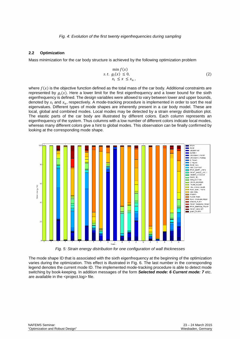
Fig. 4: Evolution of the first twenty eigenfrequencies during sampling
2.2 Optimization
Mass minimization for the car body structure is achieved by the following optimization problem
min 𝑓𝑓(𝑥𝑥) 𝑠𝑠. 𝑡𝑡. 𝑔𝑔𝑖𝑖(𝑥𝑥) ≤ 0, (2)
𝑥𝑥𝑙𝑙 ≤ 𝑥𝑥 ≤ 𝑥𝑥𝑢𝑢 , where 𝑓𝑓(𝑥𝑥) is the objective function defined as the total mass of the car body. Additional constraints are represented by 𝑔𝑔𝑖𝑖(𝑥𝑥). Here a lower limit for the first eigenfrequency and a lower bound for the sixth eigenfrequency is defined. The design variables were allowed to vary between lower and upper bounds, denoted by 𝑥𝑥𝑙𝑙 and 𝑥𝑥𝑢𝑢, respectively. A mode-tracking procedure is implemented in order to sort the real eigenvalues. Different types of mode shapes are inherently present in a car body model. These are local, global and combined modes. Local modes may be detected by a strain energy distribution plot. The elastic parts of the car body are illustrated by different colors. Each column represents an eigenfrequency of the system. Thus columns with a low number of different colors indicate local modes, whereas many different colors give a hint to global modes. This observation can be finally confirmed by looking at the corresponding mode shape.
Fig. 5: Strain energy distribution for one configuration of wall thicknesses
The mode shape ID that is associated with the sixth eigenfrequency at the beginning of the optimization varies during the optimization. This effect is illustrated in Fig. 6. The last number in the corresponding legend denotes the current mode ID. The implemented mode-tracking procedure is able to detect mode switching by book-keeping. In addition messages of the form Selected mode: 6 Current mode: 7 etc. are available in the <project.log> file.
NAFEMS Seminar: “Optimization and Robust Design”
23 – 24 March 2015 Wiesbaden, Germany

Fig. 6: Constraint history of the design constraint related to 𝑓𝑓6
2.3 Reliability Analysis
Different numerical methods, such as FORM, SORM, RSM, adaptive and crude Monte-Carlo are directly available in PERMAS [14, 15]. Here we focus on FORM. Importance sampling may be used to improve the results of the first order method. The stochastic properties of the model are estimated. It was assumed, that the thicknesses of all sheets are uncertain due to tolerances and a uniform distribution was selected for each thickness. The support is defined by the two parameters, 𝑎𝑎 and 𝑏𝑏, which are its minimum and maximum values. Since there are 27 independent sheet thicknesses, the stochastic model contains 27 basic variables. One or more failure functions can be defined to compute the probability of failure for the corresponding failure function. Each failure function 𝑔𝑔(𝑍𝑍,𝑑𝑑) describes one mode of failure. The vector 𝑍𝑍 contains the state variables, which may be results of a finite element analysis or basic variables used as direct parameters, whereas vector 𝑑𝑑 contains additional deterministic parameters. For 𝑔𝑔(𝑍𝑍,𝑑𝑑) < 0 the structure fails, 𝑔𝑔(𝑍𝑍,𝑑𝑑) = 0 is the limit state, and for 𝑔𝑔(𝑍𝑍,𝑑𝑑) > 0 the structure is said to be in a safe state. The limit state function 𝑔𝑔(𝑍𝑍) = 𝑓𝑓1(𝑍𝑍) − 𝑓𝑓 ̅, where 𝑓𝑓1 denotes the fundamental eigenfrequency of the car body and 𝑓𝑓 ̅ is a user-defined threshold value for the first eigenfrequency.
3 Conclusions Different tools to study the variability of eigenfrequencies due to uncertainties in wall thicknesses are available in PERMAS. The so-called sizing wizard in VisPER [16] can be used to complete the finite element model with respect to optimization relevant data input. Some additional entries for the SAMPLING and RELIABILITY ANALYSIS can be reused or easily added using a suitable text editor, e.g. an enhanced version of emacs [17].
4 References [1] Azadi, S., Azadi, M., Zahedi, F.: NVH analysis and improvement of a vehicle body structure
using DOE method, Journal of Mechanical Science and Technology, Vol. 23 (2009), pp. 2980—2989.
NAFEMS Seminar: “Optimization and Robust Design”
23 – 24 March 2015 Wiesbaden, Germany

[2] Costas, M., Díaz, J., Romera, L., Hernández, S.: A multi-objective surrogate-based optimization of the crashworthiness of a hybrid impact absorber, International Journal of Mechanical Sciences, Vol. 88 (2014), pp. 46—54.
[3] Doke, P., Fard, M., Jazar, R.: Vehicle concept modeling: A new technology for structures weight reduction, Procedia Engineering, Vol. 49 (2012), pp. 287--293
[4] Druesne, F.:Fast methods based on modal stability procedure to evaluate natural frequency variability for industrial shell-type structures, Finite Elements in Analysis and Design, Vol. 89 (2014), pp. 93—106
[5] Fischer, R., Kirchgäßner, B.; Reliability analysis and optimization in PERMAS, NAFEMS Seminar: Use of Stochastics in FEM Analysis, May 7-8, Wiesbaden (2003)
[6] Gollwitzer, S., Kirchgäßner, B., Fischer, R., Rackwitz, R.: PERMAS-RA/STRUREL system of programs for probabilistic reliability analysis, Structural Safety, Vol. 28 (2006), pp. 108—129
[7] KIani, M., Gandikota, I., Rais-Rohani, M., Motoyama, K.: Design of lightweight magnesium car body structure under crash and vibration constraints, Journal of Magnesium and Alloys, Vol. 2 (2014), pp. 99—108
[8] Lyu, N., Saitou, K.: Decomposition-based assembly synthesis of a three-dimensional body-in-white model for structural stiffness, Journal of Mechanical Design, Vol. 127 (2005) pp. 34--48
[9] Rashid, A. S. Y., Ramli, R., Haris, S. M., Alias, A.: Improving the dynamic characteristics of body-in-white structure using structural optimization, The Scientific World Journal, Vol 2014
[10] Sobieszczanski-Sobieski, J., Kodiyalam, S., Yang, R. Y., Optimization of car body under constraints of noise, vibration and harshness (NVH), and crash, Struct. Multidisc. Optim., Vol. 22 (2001), pp. 295—306.
[11] Yang, Y., Zhao, G. Ma, D., Xu, X.: Mode calculation and testing of a car body in white, Shock and Vibration Vol. 18 (2011), pp. 289-298
[12] Zuo, W., Li, W., Xu, T. Xuan, S., Na, J.: A complete development process of finite element software for body-in-white structure with semi-rigid beams in .NET framework, Advances in Engineering Software, Vol. 45 (2012), pp. 261—271.
[13] http://www.ncac.gwu.edu/vml/models.html [14] PERMAS Version 15: Users’ Reference Manual, INTES Publication No. 450, Stuttgart, (2014) [15] PERMAS Version 15: Examples Manual, INTES Publication No. 550, Stuttgart, (2014) [16] VisPER Version 4: VisPER Users’ Manual, INTES Publication No. 470, Stuttgart, (2014) [17] http://www.intes.de/kategorie_support/download/unix_tools
NAFEMS Seminar: “Optimization and Robust Design”
23 – 24 March 2015 Wiesbaden, Germany