Embed Size (px)
Citation preview

0
Robust Attenuation of FrequencyVarying Disturbances
Kai Zenger and Juha OrivuoriAalto University School of Electrical Engineering
Finland
1. Introduction
Systems described by differential equations with time-periodic coefficients have a longhistory in mathematical physics. Applications cover a wide area of systems ranging fromhelicopter blades, rotor-bearing systems, mechanics of structures, stability of structuresinfluenced by periodic loads, applications in robotics and micro-electromechanical systems
etc. (Rao, 2000; Sinha, 2005). Processes characterized by linear time-invariant or time-varyingdynamics corrupted by sinusoidal output disturbance belong to this class of systems. Robustand adaptive analysis and synthesis techniques can be used to design suitable controllers,which fulfill the desired disturbance attenuation and other performance characteristics of theclosed-loop system.Despite of the fact that LTP (Linear Time Periodic) system theory has been under researchfor years (Deskmuhk & Sinha, 2004; Montagnier et al., 2004) the analysis on LTPs withexperimental data has been seriously considered only recently (Allen, 2007). The importanceof new innovative ideas and products is of utmost importance in modern industrial society. Inorder to design more accurate and more economical products the importance of model-basedcontrol, involving increasingly accurate identification schemes and more effective controlmethods, have become fully recognized in industrial applications.An example of the processes related to the topic is vibration control in electrical machines,in which several research groups are currently working. Active vibration control has manyapplications in various industrial areas, and the need to generate effective but relatively
cheap solutions is enormous. The example of electrical machines considered concerns thedampening of rotor vibrations in the so-called critical speed declared by the first flexural rotorbending resonance. In addition, the electromagnetic fields in the air-gap between rotor andstator may couple with the mechanic vibration modes, leading to rotordynamic instability.The vibration caused by this resonance is so considerable that large motors often have to bedriven below the critical speed. Smaller motors can be driven also in super-critical speeds,but they have to be accelerated fast over the critical speed. Active vibration control wouldmake it possible to use the motor in its whole operation range freely, according to specifiedneeds given by the load process. Introducing characteristics of this kind for the electric drivesof the future would be a major technological break-through, a good example of an innovativetechnological development.
13
www.intechopen.com

2 Will-be-set-by-IN-TECH
In practice, the basic electromechanical models of electrical machines can be approximatedby linear time-invariant models with a sinusoidal disturbance signal entering at the so-calledcritical frequency. That frequency can also vary which makes the system model time-variable.The outline of the article is as follows. Two test processes are introduced in Section 2. Asystematic and generic model structure valid for these types of systems is presented in Section3. Three types of controllers for active vibration control are presented in Section 4 andtheir performance is verified by simulations and practical tests. Specifically the extensionto the nonlinear control algorithm presented in Section 4.4 is important, because it extendsthe optimal controller to a nonlinear one with good robustness properties with respect tovariations in rotation frequency. Conclusions are given in Section 5.
2. Problem statement
The control algorithms described in the paper were tested by two test processes to bediscussed next.
2.1 An electric machine
(a) Fig1a (b) Fig1b
Fig. 1. Test machine: A 30 kW three-phase squirrel cage induction motor with an extendedrotor shaft (a) and stator windings (b)
In electrical motors both radial and axial vibration modes are of major concern, because theylimit the speed at which the motor can be run and also shorten the lifetime of certain partsof the motor. The fundamental vibration forces are typically excited at discrete frequencies(critical frequencies), which depend on the electrodynamics of the rotor and stator (Inman,2006). In some machines the critical frequency can be passed by accelerating the rotor speedfast beyond it, but specifically in larger machines that is not possible. Hence these machinesmust be run at subcritical frequencies. It would be a good idea to construct an actuator, whichwould create a separate magnetic field in the airgap between the stator and rotor. That wouldcause a counterforce, which would attenuate the vibration mode of the rotor. Running therotor at critical speeds and beyond will need a stable and robust vibration control system,because at different speeds different vibration modes also wake.
292 Recent Advances in Robust Control – Novel Approaches and Design Methods
www.intechopen.com

Robust Attenuation of Frequency
Varying Disturbances 3
In Fig.1 a 30 kW induction machine is presented, provided with such a new actuator, whichis a coil mounted in the stator slots of the machine (b). The electromechanical actuator is anextra winding, which, due to the controlled current, produces the required counter force todamp the rotor vibrations. The actuator is designed such that the interaction with the normaloperation of the machine is minimal. More on the design and modelling of the actuator canbe found in (Laiho et al., 2008).Some of the machine parameters are listed in Table 1. The vibration of the rotor is continuouslymeasured in two dimensions and the control algorithm is used to calculate the control currentfed into the coil. The schema of the control arrangement is shown in Fig.2. The idea is to
Fig. 2. Rotor vibration control by a built-in new actuator
generate a control force to the rotor through a new actuator consisting of extra windingsmounted in the stator slots. An adaptive model-based algorithm controls the currents tothe actuator thus generating a magnetic field that induces a force negating the disturbanceforce exited by the mass imbalance of the rotor. The configuration in the figure includes anexcitation force (disturbance) consisting of rotation harmonics and harmonics stemming from
the induction machine dynamics. The control force and the disturbance exert a force to therotor, which results in a rotor center displacement. If the dynamic compensation signal ischosen cleverly, the rotor vibrations can be effectively reduced.In practical testing the setup shown in Fig.3 has been used. The displacement of the rotor intwo dimensions (xy) is measured at one point with displacement transducers, which give avoltage signal proportional to the distance from sensor to the shaft. A digital tachometer at theend of the rotor measures the rotational frequency. The control algorithms were programmedin Matlab/Simulink model and the dSpace interface system and the Real-Time Workshopwere used to control the current fed to the actuator winding.
2.2 An industrial rolling process
The second tests were made by a rolling process consisting of a reel, hydraulic actuator andforce sensor. The natural frequency of the process was 39 Hz, and the hydraulic actuator actsboth as the source of control forces and as a support for the reel. The actuator is connected tothe support structures through a force sensor, thus providing information on the forces actingon the reel. The test setup is shown in Fig.4 and the control schema is presented in Fig.5.
293Robust Attenuation of Frequency Varying Disturbances
www.intechopen.com

4 Will-be-set-by-IN-TECH
Parameter Value Unit
supply frequency 50 Hzrated voltage 400 Vconnection delta -
rated current 50 Arated power 30 kW
number of phases 3 -number of poles 2 -
rated slip 1 %rotor mass 55.8 kg
rotor shaft length 1560 mmcritical speed 37.5 Hz
width of the air-gap 1 mm
Table 1. Main parameters of the test motor
Co
ntr
ol vo
lta
ge
ADCDAC2 -> 3 phase
conversion
Control
algorithm
dSpace
Stator & actuator
Rotor
Stator & actuator
Measurements
Tacho
Bearing Bearing
1m 2mcF dF
Process
Current
amplifier
Measured signals
1
2
c
d
m = rotor displacement
m = rotational frequency
F = control force
F = disturbance force
Fig. 3. Schema of the test setup (motor)
3. Modeling and identification
Starting from the first principles of electromagnetics (Chiasson, 2005; Fuller et al., 1995) and
structure mechanics, the vibration model can for a two-pole cage induction machine bewritten in the form (Laiho et al., 2008)
q = Aq + Bv + G fex
urc = Cq(1)
where q denotes the states (real and complex) of the system, v is the control signal of theactuator, fex is the sinusoidal disturbance causing the vibration at the critical frequency, and
urc is the radial rotor movement in two dimensions. The matrices A, B, G and C are constant.The constant parameter values can be identified by the well-known methods(Holopainen et al., 2004; Laiho et al., 2008; Repo & Arkkio, 2006). The results obtained
294 Recent Advances in Robust Control – Novel Approaches and Design Methods
www.intechopen.com

Robust Attenuation of Frequency
Varying Disturbances 5
Force sensor
Reel
Hydraulic actuator
Reel
disturbanceF controlF
measuredF
Fig. 4. The test setup (industrial rolling process)
Co
ntr
ol vo
lta
ge
DAC ADCControl
algorithm
dSpace
1 kHz
Measurements
1m1c
cF
Process
1
1
c
d
m = sensed force
c = hydraulic pressure
F = control force
F = disturbance force
Hydraulic
valve
dF
Me
asu
red
sig
na
ls
Fig. 5. The controller schema
by using finite-element (FE) model as the "real" process have been good and accurate(Laiho et al., 2007), when both prediction error method (PEM) and subspace identification(SUB) have been used. Since the running speed of the motor was considered to be below60 Hz, the sampling rate was chosen to be 1 kHz. A 12th order state-space model was usedas the model structure (four inputs and two outputs corresponding to the control voltages,rotor displacements and produced control forces in two dimensions). The model order was
chosen based on the frequency response calculated from the measurement data, from whichthe approximate number of poles and zeros were estimated.In identification a pseudo random (PSR) control signal was used in control inputs. Thatexcites rotor dynamics on a wide frequency range, which in limited only by the samplingrate. However, because the second control input corresponds to the rotor position and has abig influence on the produced force a pure white noise signal cannot be used here. Therefore
295Robust Attenuation of Frequency Varying Disturbances
www.intechopen.com

6 Will-be-set-by-IN-TECH
the model output of the rotor position added with a small PSR signal to prevent correlationwas used as the second control input. After identification the model was validated by usingindependent validation data. The fit was larger than 80 per cent, which was considered to beadequate for control purposes. The results have later been confirmed by tests carried out byusing the real test machine data, and the results were found to be equally good.The model structure is then as shown in Fig.6, where the actuator model and electromechanicmodel of the rotor have been separated, and the sinusoidal disturbance term is used to modelthe force that causes the radial vibration of the rotor. In Fig.6a the models of the actuatorand rotor have been separated and the disturbance is modelled to enter at the input of therotor model. The internal feedback shown is caused by the unbalanced magnetic pull (UMP),which means that the rotor when moved from the center position in the airgap causes anextra distortion in the magnetic field. That causes an extra force, which can be taken intoconsideration in the actuator model. However, in practical tests it is impossible to separate themodels of the actuator and rotor dynamics, and therefore the model in Fig.6b has been usedin identification. Because the models are approximated by linear dynamics, the sinusoidal
disturbance signal can be moved to the process output, and the actuator and rotor models canbe combined.In Fig. 6a the 4-state dynamical (Jeffcott) model for the radial rotor dynamics is
xr(t) = Arx(t) + Brur(t)yr(t) = Crx(t)
(2)
where yr is the 2-dimensional rotor displacement from the center axis in xy-coordinates, andur is the sum of the actuator and disturbance forces. The actuator model is
xa(t) = Aaxa(t) +[
Ba1 Ba2
][
yr(t)u(t)
]
ya(t) = Caxa(t)(3)
where ya are the forces generated by the actuator, and u are the control voltages fed into thewindings. The self-excited sinusoidal disturbance signal is generated by (given here in twodimensions)
xd(t) = Adxd(t) =
⎡
⎢⎢⎣
0 1 0 0
−ω2d 0 0 0
0 0 0 1
0 0 −ω2d 0
⎤
⎥⎥⎦
xd(t)
d(t) = Cdxd(t) =
[1 0 0 00 0 1 0
]
xd(t)
(4)
where ωd is the angular frequency of the disturbance and d(t) denotes the disturbance forcesin xy-directions. The initial values of the state are chosen such that the disturbance consists oftwo sinusoidal signals with 90 degree phase shift (sine and cosine waves). The initial valuesare then
xd(0) =
[xsin(0)xcos(0)
]
=
⎡
⎢⎢⎣
0Aωd
A0
⎤
⎥⎥⎦
296 Recent Advances in Robust Control – Novel Approaches and Design Methods
www.intechopen.com

Robust Attenuation of Frequency
Varying Disturbances 7
where A is the amplitude of the disturbance. The models of the actuator, rotor and disturbancecan be combined into one state-space representation
xp(t) = Apxp(t) + Bpu(t) =
⎡
⎣
Ar BrCa BrCd
Ba1Cr Aa 00 0 Ad
⎤
⎦ xp(t) +
⎡
⎣
0Ba2
0
⎤
⎦ u(t)
yr(t) = Cpxp(t) =[
Cr 0 0]
xp(t)
(5)
with
xp =
⎡
⎣
xr
xa
xd
⎤
⎦
As mentioned, the actuator and rotor model can be combined and the disturbance canbe moved to enter at the output of the process (according to Fig. 6b). The state-space
representation of the actuator-rotor model is then
xar(t) = Aarxar(t) + Baru(t)yar(t) = Carxar(t)
(6)
where u is a vector of applied control voltages and yar is vector of rotor displacements. Thewhole system can be modeled as
xp(t) = Apxp(t) + Bpup(t) =
[Aar 00 Ad
]
xp(t) +
[Bar
0
]
u(t)
yr(t) = Cpxp(t) =[
Car Cd
]xp(t)
(7)
with
xp(t) =
[xar(t)xd(t)
]
The process was identified with a sampling frequency of 1 kHz, which was considered
adequate since the running speed of the motor was about 60 Hz and therefore well below100 Hz. Pseudorandom signals were used as control forces in both channels separately, andthe prediction error method (PEM) was used (Ljung, 1999) to identify a 12th order state-spacerepresentation of the system.The identified process model is compared to real process data, and the results are shown inFigs.7 and 8, respectively. The fit in x and y directions were calculated as 72.5 % and 80.08 %,which is considered to be appropriate. From the frequency domain result it is seen that forlower frequency the model agrees well with response obtained form measured data, but inhigher frequencies there is a clear difference. That is because the physical model used behindthe identification is only valid up to a certain frequency, and above that there exist unmodelleddynamics.
4. Control design
In the following sections different control methods are presented for vibration control of singleor multiple disturbances with a constant or varying disturbance frequencies. Two of themethods are based on the linear quadratic gaussian (LQ) control, and one belongs to the classof higher harmonic control algorithms (HHC), which is also known as convergent control. If the
297Robust Attenuation of Frequency Varying Disturbances
www.intechopen.com

8 Will-be-set-by-IN-TECH
aG
dG
rG( )ry t
( )d t
( )ay t
( )ru t
( )u t+
+
a
d
r
G Actuator
G Disturbance
G Rotor
=
=
=
(a) Fig6a
dG
proG
( )d t
( )proy t ( )y t+
+
( )u t
process model
disturbance model
pro
d
G
G
=
=
(b) Fig6b
Fig. 6. Process models for the actuator, rotor and sinusoidal disturbance
Fig. 7. Validation of the actuator-rotor model in time domain
Fig. 8. Validation of the actuator-rotor model in frequency domain
298 Recent Advances in Robust Control – Novel Approaches and Design Methods
www.intechopen.com

Robust Attenuation of Frequency
Varying Disturbances 9
sinusoidal disturbance frequency signal varies in frequency, the algorithms must be modifiedby combining them and using direct frequency measurement or frequency tracking.
4.1 Direct optimal feedback design
In this method the suppressing of tonal disturbance is posed as a dynamic optimizationproblem, which can be solved by the well-known LQ theory. The idea is again that the modelgenerating the disturbance is embedded in the process model, and that information is thenautomatically used when minimizing the design criterion. That leads to a control algorithmwhich inputs a signal of the same amplitude but opposite phase to the system thus cancelingthe disturbance. The problem can be defined in several scenarios, e.g. the disturbance can bemodelled to enter at the process input or output, the signal to be minimized can vary etc.Starting from the generic model
x(t) = Ax(t) + Bu(t) =
[Ap 00 Ad
]
x(t) +
[Bp
0
]
u(t)
y(t) =[
Cp Cd
]x(t)
(8)
the control criterion is set
J =
∞∫
0
(
zT(τ)Qz(τ) + uT(τ)Ru(τ))
dτ (9)
where z is a freely chosen performance variable and Q ≥ 0, R > 0 are the weighing matricesfor the performance variable and control effort. By inserting z(t) = Czx(t) the criterionchanges into the standard LQ form
J =
∞∫
0
(
xT(τ)CTz QCzx(τ) + uT(τ)Ru(τ)
)
dτ (10)
The disturbance dynamics can be modelled as
xd(t) = Adxd(t) =
⎡
⎢⎢⎢⎣
Ad1 · · · 0 0...
. . ....
...0 · · · Adn 0
0 · · · 0 −ǫ
⎤
⎥⎥⎥⎦
xdn(t)
d(t) = Cdxd(t) =[
Cd1 · · · Cdn 0]
xdn(t)
(11)
where
Adn =
[0 1
−ω2dn −ε
]
, i = 1, 2, ..., n
and the initial valuesx(0) =
[xT
d1(0) · · · xTdn(0) b
]T
According to the formalism a sum of n sinusoidal disturbance components (angularfrequencies ωdn) enter the system. The very small number ǫ is added in order the augmentedsystem to be stabilizable, which is needed for the solution to exist. The damping of theresulting sinusoidal is so low that it does not affect the practical use of the optimal controller.
299Robust Attenuation of Frequency Varying Disturbances
www.intechopen.com

10 Will-be-set-by-IN-TECH
The constant b can be used for a constant bias term in the disturbance. Compare thedisturbance modelling also to that presented in equations (4) and (5).To minimize of sinusoidal disturbances the following performance variable can be chosen
z(t) =
[
Cp
...[
Cd1 · · · Cdn 0]
]
x(t) =
[
Cp
... Cd
]
x(t) = Czx(t) (12)
which leads to the cost function (10)The solution of the LQ problem can now be obtained by standard techniques(Anderson & Moore, 1989) as
u(t) = −Lx(t) = −R−1BTSx(t) (13)
where S is the solution of the algebraic Riccati equation
ATS + SA − SBR−1BTS + Q = 0 (14)
It is also possible to choose simply z(t) = x(t) in (9). To force the states approach zero it is inthis case necessary to introduce augmented states
xaug(t) =
t∫
0
(yar(τ) + d(τ)) dτ =[
Car Cd
]t∫
0
([xar(τ)
T xd(τ)T]T
)
dτ (15)
The system to which the LQ design is used is then
x(t) =
[xp(t)
xaug(t)
]
=
⎡
⎢⎢⎢⎢⎣
Ap
... 0
· · ·... · · ·
[Car Cd
] ... 0
⎤
⎥⎥⎥⎥⎦
︸ ︷︷ ︸
Aaug
x(t) +
⎡
⎣
Bp
· · ·
0
⎤
⎦
︸ ︷︷ ︸
Baug
u(t)
yr(t) =[
Cp 0]
︸ ︷︷ ︸
Caug
x(t)
(16)
In this design the weights in Q corresponding to the augmented states should be set toconsiderably high values, e.g. values like 105 have been used.Usually a state observer must be used to implement the control law. For example, in theconfiguration shown in Fig.6a (see also equation (5)) that has the form
˙x(t) = Ap x(t) + Bpu(t) + K (yr(t)− yr(t))yobs = x(t)
(17)
The gain in the estimator can be chosen based on the duality between the LQ optimalcontroller and the estimator. The state error dynamics x(t) = x(t)− x(t) follows the dynamics
˙x(t) =(
Ap − KCp)
x(t) (18)
300 Recent Advances in Robust Control – Novel Approaches and Design Methods
www.intechopen.com

Robust Attenuation of Frequency
Varying Disturbances 11
which is similar toxN(t) = ANxN(t) + BNuN(t) (19)
with AN = ATp , BN = CT
p , KN = KT and uN(t) = −KNxN(t). The weighting matrix KN canbe determined by minimizing
Jobs =
∞∫
0
(
xN(t)TQobsxN(t) + uN(t)TRobsuN(t)
)
dt (20)
where the matrices Qobs and Robs contain the weights for the relative state estimation errorand its convergence rate.The optimal control law (13) can now be combined with the observer model (17). Includingthe augmented states (15) the control law can be stated as
xLQ(t) =
[˙x(t)
˙xaug(t)
]
=
([Ap − KCp 0
Cp 0
]
−
[Bp
0
]
L
)
︸ ︷︷ ︸
ALQ
xLQ(t) +
[K0
]
︸ ︷︷ ︸
BLQ
yr(t)
uLQ(t) = −L︸︷︷︸
CLQ
xLQ(t)
(21)
where yr is the rotor displacement, uLQ is the optimal control signal, and ALQ, BLQ and CLQ
are the parameters of the controller.
4.2 Convergent controller
The convergent control (CC) algorithm (also known as instantaneous harmonic control(IHC) is a feedforward control method to compensate a disturbance at a certain frequency(Daley et al., 2008). It is somewhat similar to the well-known least means squares compensator(LMS), (Fuller et al., 1995; Knospe et al., 1994) which has traditionally been used in manyfrequency compensating methods in signal processing. A basic schema is presented in Fig.9.The term r is a periodic signal of the same frequency as d, but possibly with a different
0
( )N
i
ì
h r k i=
−∑ +
( )r k
( )d k
( )e k( )u k
Fig. 9. Feedforward compensation of a disturbance signal
amplitude and phase. The idea is to change the filter parameters hi such that the signal ucompensates the disturbance d. The standard LMS algorithm that minimizes the squarederror can be derived to be as
hi(k + 1) = hi(k)− αr(k − i)e(k) (22)
301Robust Attenuation of Frequency Varying Disturbances
www.intechopen.com

12 Will-be-set-by-IN-TECH
where α is a tuning parameter (Fuller et al., 1995; Tammi, 2007). In the CC algorithm theprocess dynamics is presented by means of the Fourier coefficients as
EF(k) = GFUF(k) + DF(k) (23)
where GF is the complex frequency response of the system and the symbols EF, UF and DF
are the Fourier coefficients of the error, control and disturbance signals. For example
EωnF =
1
N
N−1
∑k=0
e(k)e−2iπkn/N≈ e(k)e−iωnt
where N is the number of samples in one signal period, and n is the number of the spectralline of the corresponding frequency. If the sampling time is Ts, then t = kTs.The criterion to be minimized is J = E∗
FEF which gives
UF = − (G∗FGF)
−1 G∗FDF = −AFDF (24)
where ∗ denotes the complex transpose. The pseudoinverse is used if necessary whencalculating the inverse matrix. In terms of Fourier coefficients the Convergent ControlAlgorithm can be written as
UF(k + 1) = βUF(k)− αAFEF(k) (25)
where α and β are tuning parameters. It can be shown (Daley et al., 2008; Tammi, 2007) that
the control algorithm can be presented in the form of a linear time-invariant pulse transferfunction
Gcc(z) =U(z)
Y(z)= β
Re
(
GF
(
eiωk
)−1)
z2 − αRe
(
GF
(
eiωk
)−1e−iωkTs
)
z
z2 − 2α cos (ωkTs) z + α2(26)
where Y(z) is the sampled plant output and U(z) is the sampled control signal.The convergent controller can operate like an LMS controller in series with the plant, by usinga reference signal r proportional to the disturbance signal to be compensated. The ’plant’
can here mean also the process controlled by a wide-frequency band controller like the LQcontroller for instance.
Process
Feedback control
Convergent control( )ry t( )extu t( )r t
( )LQu t
( )u t+
Adaptation
signal
Fig. 10. Convergent controller in series with a controlled plant
302 Recent Advances in Robust Control – Novel Approaches and Design Methods
www.intechopen.com

Robust Attenuation of Frequency
Varying Disturbances 13
Alternatively, the CC controller can be connected in parallel with the LQ-controller, thenhaving the plant output as the input signal. Several CC controllers (tuned for differentfrequencies) can also be connected in parallel in this configuration, see Fig.11.
Process
LQ-controller
( )CCu k
( )LQu k
( )ry k( )u k
+ +
CC-controller
Fig. 11. Convergent controller connected in parallel with the LQ controller
4.3 Simulations and test runs
The controller performance was tested in two phases. Firstly, extensive simulations by using afinite element (FE) model of the electrical machine and actuator were carried out. Secondly, thecontrol algorithms were implemented in the test machine discussed in Section 2.1 by using adSpace system as the program-machine interface. The disturbance frequency was 49.5 Hz, and
the controller was discretized with the sampling frequency 1 kHz. Time domain simulationsare shown in Figs. 12 and 13. The damping is observed to be about 97 per cent, which is agood result.
Fig. 12. Simulation result in time domain (rotor vibration in x-direction)
The critical frequency of the 30 kW test motor was 37.7 Hz. However, due to vibrations therotor could not be driven at this speed in open loop, and both the identification and initialcontrol tests were performed at 32 Hz rotation frequency. In the control tests the LQ controller
was used alone first, after which the CC controller was connected, in order to verify theperformance of these two control configurations. Both controllers were discretized at 5 kHzsampling rate.
303Robust Attenuation of Frequency Varying Disturbances
www.intechopen.com

14 Will-be-set-by-IN-TECH
Fig. 13. Simulated rotor vibration in xy-plot
The test results are shown in Figs. 14-17. In Fig.14 the control signal and rotor vibrationamplitude are shown, when the machine was driven at 32.5 Hz. The LQ controller wasused first alone, and then the CC controller was connected. It is seen that the CC controllerimproves the performance somewhat, and generally the vibration damping is good and well
comparable to the results obtained by simulations. The same can be noticed from the xy-plotshown in Fig.15.
Fig. 14. Test machine runs at 32 Hz speed: Control voltage and rotor displacement inx-direction
Next, the operation speed was increased to the critical frequency 37.5 Hz. Controller(s) tunedfor this frequency could be driven without any problems at this speed. Similar results asabove are shown in Figs.16 and 17. It is remarkable that now connecting the CC controller onimproved the results more than before. So far there is no clear explanation to this behaviour.
4.4 Nonlinear controller
If the frequency of the disturbance signal is varying, the performance of a controller with
constant coefficients deteriorates considerably. An immediate solution to the probleminvolves the use of continuous gain scheduling, in which the controller coefficients aremodified according to the current disturbance frequency. To this end the disturbance
304 Recent Advances in Robust Control – Novel Approaches and Design Methods
www.intechopen.com

Robust Attenuation of Frequency
Varying Disturbances 15
Fig. 15. Test machine runs at 32 Hz speed: xy-plot
Fig. 16. Test machine runs at 37.5 Hz critical speed: Control voltage and rotor displacementin x-direction
Fig. 17. Test machine runs at 37.5 Hz critical speed: xy-plot
305Robust Attenuation of Frequency Varying Disturbances
www.intechopen.com

16 Will-be-set-by-IN-TECH
frequency (usually the rotating frequency) has to be measured of tracked (Orivuori & Zenger,2010; Orivuori et al., 2010). The state estimator can be written in the form
˙x(t, ωhz) = (A (ωhz)− K (ωhz)C) x(t, ωhz) + Bu(t) + K(ωhz)y(t) (27)
where it has been assumed that the model topology is as in Fig.6b and the disturbance modelis included in the system matrix A. The matrix K changes as a function of frequency as
K(ωhz) =[
f1(ωhz) f2(ωhz) · · · fn(ωhz)]T
(28)
where fi are suitable functions of frequency. Solving the linear optimal control problem in afrequency grid gives the values of K, which can be presented like in Fig.18 The functions fi
Fig. 18. Projections of the hypersurface to the elements of K
can be chosen to be polynomials, so that the feedback gain has the form
K(ωhz) =
⎡
⎢⎢⎢⎢⎢⎢⎢⎢⎣
a11 a12 · · · a1m
a21 a22 · · · a2m
......
. . ....
an1 an2 · · · anm
⎤
⎥⎥⎥⎥⎥⎥⎥⎥⎦
uω(ωhz) (29)
306 Recent Advances in Robust Control – Novel Approaches and Design Methods
www.intechopen.com

Robust Attenuation of Frequency
Varying Disturbances 17
where aij are the polynomial coefficients and
uω(ωhz) =[
ωm−1hz · · · ω2
hz ωhz 1]T
(30)
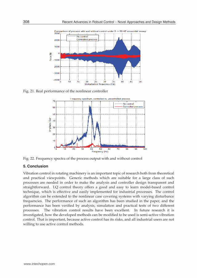
The optimal control gain L(ωhz) can be computed similarly.The controller was tested with the industrial rolling process presented in Section 2.2. Asinusoidal sweep disturbance signal was used, which corresponds to a varying rotationalspeed of the reel with constant width. The rotation frequency ranged over the frequencyrange 5 Hz..50 Hz. Before the practical tests the theoretical performance of the controller wasanalyzed. The result is shown in Fig.19, which shows a neat damping of the vibration nearthe critical frequency 39 Hz. Simulation and practical test results are shown in Figs.20 and
Fig. 19. Theoretical damping achieved with the nonlinear controller
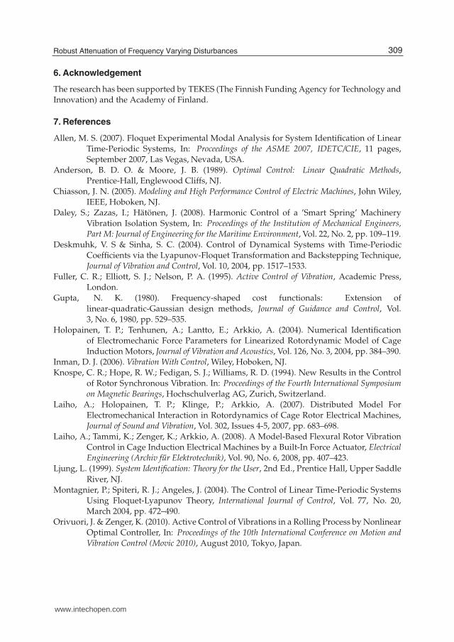
21, respectively. The controller turns out to be effective over the whole frequency range thedamping ratio being 99 per cent in simulation and about 90 per cent in practical tests. Theresult of the good performance of the nonlinear controller is further verified by the outputspectrum of the process obtained with and without control. The result is shown in Fig.22.
Fig. 20. Simulated performance of the nonlinear controller
307Robust Attenuation of Frequency Varying Disturbances
www.intechopen.com
18 Will-be-set-by-IN-TECH
Fig. 21. Real performance of the nonlinear controller
Fig. 22. Frequency spectra of the process output with and without control
5. Conclusion
Vibration control in rotating machinery is an important topic of research both from theoreticaland practical viewpoints. Generic methods which are suitable for a large class of suchprocesses are needed in order to make the analysis and controller design transparent andstraightforward. LQ control theory offers a good and easy to learn model-based controltechnique, which is effective and easily implemented for industrial processes. The controlalgorithm can be extended to the nonlinear case covering systems with varying disturbancefrequencies. The performance of such an algorithm has been studied in the paper, and theperformance has been verified by analysis, simulation and practical tests of two differentprocesses. The vibration control results have been excellent. In future research it isinvestigated, how the developed methods can be modified to be used is semi-active vibrationcontrol. That is important, because active control has its risks, and all industrial users are not
willing to use active control methods.
308 Recent Advances in Robust Control – Novel Approaches and Design Methods
www.intechopen.com
Robust Attenuation of Frequency
Varying Disturbances 19
6. Acknowledgement
The research has been supported by TEKES (The Finnish Funding Agency for Technology andInnovation) and the Academy of Finland.
7. References
Allen, M. S. (2007). Floquet Experimental Modal Analysis for System Identification of LinearTime-Periodic Systems, In: Proceedings of the ASME 2007, IDETC/CIE, 11 pages,September 2007, Las Vegas, Nevada, USA.
Anderson, B. D. O. & Moore, J. B. (1989). Optimal Control: Linear Quadratic Methods,Prentice-Hall, Englewood Cliffs, NJ.
Chiasson, J. N. (2005). Modeling and High Performance Control of Electric Machines, John Wiley,IEEE, Hoboken, NJ.
Daley, S.; Zazas, I.; Hätönen, J. (2008). Harmonic Control of a ’Smart Spring’ MachineryVibration Isolation System, In: Proceedings of the Institution of Mechanical Engineers,Part M: Journal of Engineering for the Maritime Environment, Vol. 22, No. 2, pp. 109–119.
Deskmuhk, V. S & Sinha, S. C. (2004). Control of Dynamical Systems with Time-PeriodicCoefficients via the Lyapunov-Floquet Transformation and Backstepping Technique,Journal of Vibration and Control, Vol. 10, 2004, pp. 1517–1533.
Fuller, C. R.; Elliott, S. J.; Nelson, P. A. (1995). Active Control of Vibration, Academic Press,London.
Gupta, N. K. (1980). Frequency-shaped cost functionals: Extension of
linear-quadratic-Gaussian design methods, Journal of Guidance and Control, Vol.3, No. 6, 1980, pp. 529–535.
Holopainen, T. P.; Tenhunen, A.; Lantto, E.; Arkkio, A. (2004). Numerical Identificationof Electromechanic Force Parameters for Linearized Rotordynamic Model of CageInduction Motors, Journal of Vibration and Acoustics, Vol. 126, No. 3, 2004, pp. 384–390.
Inman, D. J. (2006). Vibration With Control, Wiley, Hoboken, NJ.Knospe, C. R.; Hope, R. W.; Fedigan, S. J.; Williams, R. D. (1994). New Results in the Control
of Rotor Synchronous Vibration. In: Proceedings of the Fourth International Symposiumon Magnetic Bearings, Hochschulverlag AG, Zurich, Switzerland.
Laiho, A.; Holopainen, T. P.; Klinge, P.; Arkkio, A. (2007). Distributed Model ForElectromechanical Interaction in Rotordynamics of Cage Rotor Electrical Machines,Journal of Sound and Vibration, Vol. 302, Issues 4-5, 2007, pp. 683–698.
Laiho, A.; Tammi, K.; Zenger, K.; Arkkio, A. (2008). A Model-Based Flexural Rotor VibrationControl in Cage Induction Electrical Machines by a Built-In Force Actuator, ElectricalEngineering (Archiv fur Elektrotechnik), Vol. 90, No. 6, 2008, pp. 407–423.
Ljung, L. (1999). System Identification: Theory for the User, 2nd Ed., Prentice Hall, Upper Saddle
River, NJ.Montagnier, P.; Spiteri, R. J.; Angeles, J. (2004). The Control of Linear Time-Periodic Systems
Using Floquet-Lyapunov Theory, International Journal of Control, Vol. 77, No. 20,March 2004, pp. 472–490.
Orivuori, J. & Zenger, K. (2010). Active Control of Vibrations in a Rolling Process by NonlinearOptimal Controller, In: Proceedings of the 10th International Conference on Motion andVibration Control (Movic 2010), August 2010, Tokyo, Japan.
309Robust Attenuation of Frequency Varying Disturbances
www.intechopen.com

20 Will-be-set-by-IN-TECH
Orivuori, J.; Zazas, I.; Daley, S. (2010). Active Control of a Frequency Varying TonalDisturbance by Nonlinear Optimal Controller with Frequency Tracking, In:Proceedings of the IFAC Workshop of Periodic Control Systems (Psyco 2010), August 2010,Antalya, Turkey.
Rao, J. D. (2000). Vibratory Condition Monitoring of Machines, Narosa Publishing House, NewDelhi, India.
Repo, A-K. & Arkkio, A. (2006). Numerical Impulse Response Test to Estimate Circuit-ModelParameters for Induction Machines, IEE Proceedings, Electric Power Applications, Vol.153, No. 6, 2006, pp. 883–890.
Sinha, S. C. (2005). Analysis and Control of Nonlinear Dynamical Systems with PeriodicCoefficients, In: Proceedings of the Workshop on Nonlinear Phenomena, Modeling and theirapplications, SP-Brazil, Eds. JM Balthazar, RMLRF Brasil, EEN Macau, B. R. Pontesand L C S Goes, 2-4 May, 2005.
Tammi, K. (2007). Active Control of Rotor Vibrations - Identification, Feedback, Feedforward andRepetitive Control Methods, Doctoral thesis, VTT Publications 634, Espoo: Otamedia.
Sievers, L. A.; Blackwood, G. H.; Mercadal, M.; von Flotow, A. H. (1991). MIMO NarrowbandDisturbance Rejection Using Frequency Shaping of Cost Functionals, In: Proceedingsof American Control Conference, Boston, MA, USA.
310 Recent Advances in Robust Control – Novel Approaches and Design Methods
www.intechopen.com

Recent Advances in Robust Control - Novel Approaches andDesign MethodsEdited by Dr. Andreas Mueller
ISBN 978-953-307-339-2Hard cover, 462 pagesPublisher InTechPublished online 07, November, 2011Published in print edition November, 2011
InTech EuropeUniversity Campus STeP Ri Slavka Krautzeka 83/A 51000 Rijeka, Croatia Phone: +385 (51) 770 447 Fax: +385 (51) 686 166www.intechopen.com
InTech ChinaUnit 405, Office Block, Hotel Equatorial Shanghai No.65, Yan An Road (West), Shanghai, 200040, China
Phone: +86-21-62489820 Fax: +86-21-62489821
Robust control has been a topic of active research in the last three decades culminating in H_2/H_\infty and\mu design methods followed by research on parametric robustness, initially motivated by Kharitonov'stheorem, the extension to non-linear time delay systems, and other more recent methods. The two volumes ofRecent Advances in Robust Control give a selective overview of recent theoretical developments and presentselected application examples. The volumes comprise 39 contributions covering various theoretical aspects aswell as different application areas. The first volume covers selected problems in the theory of robust controland its application to robotic and electromechanical systems. The second volume is dedicated to special topicsin robust control and problem specific solutions. Recent Advances in Robust Control will be a valuablereference for those interested in the recent theoretical advances and for researchers working in the broad fieldof robotics and mechatronics.
How to referenceIn order to correctly reference this scholarly work, feel free to copy and paste the following:
Kai Zenger and Juha Orivuori (2011). Robust Attenuation of Frequency Varying Disturbances, RecentAdvances in Robust Control - Novel Approaches and Design Methods, Dr. Andreas Mueller (Ed.), ISBN: 978-953-307-339-2, InTech, Available from: http://www.intechopen.com/books/recent-advances-in-robust-control-novel-approaches-and-design-methods/robust-attenuation-of-frequency-varying-disturbances