Embed Size (px)
Citation preview

1
Robert B. Elliott is the author of BUILD AND FLYTHE FIRST FLYERS and creator of THE TOOTHPICKAIRFORCE™ concept. Especially for the Centennial ofFlight Elliott has modified parts of his book and designedadditional gliders to demonstrate the progress the Wrightsmade with their first four flyers. Building and flyingtoothpick glider replicas of the Wright gliders and flyersrequire the student use and understand the sameknowledge of flight and control surfaces the Wrightspioneered one hundred years ago! Ladies and gentlemen,prepare for flight!
Wright Brothers Aeroplane Co. replicas of 1900 (front left), 1902 (right), and1901 (rear) glider at Jockey’s Ridge State Park, NC, October of 2002. (photo -R. B. Elliott)
Copyright © 2003 by Booger Red’s Books, Inc. All rights reserved. No part of this work maybe reproduced by any means, except as may be expressly permitted by the 1976 Copyright Act orin writing by BOOGER RED’S BOOKS, Inc.
Is a registered Trade Name ® and TradeMark ™ of Booger Red’s Books, Inc.

2
BUILD AND FLY THE WRIGHT FLYERS THE TOOTHPICK AIRFORCE™ (TA) concept is actually a formula
for achieving balance in design and construction that allows the reader to buildflying replicas of any aircraft of any era using just paper, paste and toothpicks!To celebrate the Centennial of Flight you can build the Wright 1900 glider, the1901, 1902, and the flyer that made the world’s first controlled, powered flight, atKitty Hawk in December of 1903.
Toothpick glider replicas of the Wrights’ first flyers, that fly just like the realaircraft!
Follow the Wrights’ progress with replicas of each of their first mannedaircraft, learn the secrets that each successive flyer revealed!
From the wing patterns on the following pages you can construct flying gliderreplicas of the airplanes that marked man’s first successful flight.
Creasing the paper along the “fold line”makes mirror image wing surfaces and partswhen cut out.
Always cut on the solid lines, bend andcrease on the dotted lines.Shown are all the supplies you will need.The clippers will be very handy.

3
Making Gliders Fly!
Building gliders that really flycan be a challenge. First we need toknow why they fly, and there is nobetter way to do that than to look to themen who invented flight. Wilbur andOrville Wright planned, experimented,worked hard and practiced glidingcontinuously to conquer the air.
Along the way, they or their fellow pioneer flyers found a lot of ways todescribe the mechanics of flight and invented special aviation terms and words youwill need to know.
We know now, flight is possible only when there is a balance between threeabsolute necessities: lift, control, and thrust. But in 1900 the Wright brothershad to figure this out for themselves. These words have special meaning inaviation:
Lift - The force exerted by the movement of air on an airfoil, being oppositethe force of gravity and causing an aircraft to stay in the air.
Control - To hold in restraint or check; to regulate; to govern.Thrust - To push or drive with force.In their experiments with their 1900 and 1901 gliders the Wrights used
information from other pioneers of flight. But this information on how wingscreated lift did not work the way it was supposed to. The brothers built one of thefirst wind tunnels to test the data, and found the data was wrong. The Wrights’wind tunnel experiments and experience on their first gliders led to building the1902 glider, which had new and advanced controls.
The 1902 glider was larger than any of the other gliders built anywhere inthe world up to then, making some of the longest glides in history possible. Withthis glider they were able to perfect their control system, for which they received apatent in 1906. This three axis control system allowed for adjustment to yaw, pitchand roll, and is the basis for all modern aircraft flight.
The final challenge for the Wright brothers was in developing their ownengine, and an efficient propeller. When the Wrights finally flew on December17th, 1903, they had finally mastered lift, control, and thrust! The descriptions anddefinitions on the following page will be helpful in constructing toothpick replicasof real gliders. Once you have mastered the basic mechanics of flight, experimentwith camber in Advanced Wing Structure.
4
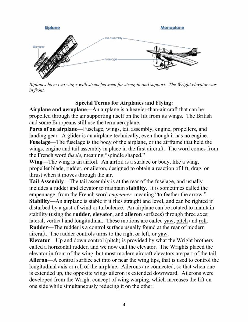
Biplanes have two wings with struts between for strength and support. The Wright elevator wasin front.
Special Terms for Airplanes and Flying:Airplane and aeroplane—An airplane is a heavier-than-air craft that can bepropelled through the air supporting itself on the lift from its wings. The Britishand some Europeans still use the term aeroplane.Parts of an airplane—Fuselage, wings, tail assembly, engine, propellers, andlanding gear. A glider is an airplane technically, even though it has no engine.Fuselage—The fuselage is the body of the airplane, or the airframe that held thewings, engine and tail assembly in place in the first aircraft. The word comes fromthe French word fusele, meaning “spindle shaped.”Wing—The wing is an airfoil. An airfoil is a surface or body, like a wing,propeller blade, rudder, or aileron, designed to obtain a reaction of lift, drag, orthrust when it moves through the air.Tail Assembly—The tail assembly is at the rear of the fuselage, and usuallyincludes a rudder and elevator to maintain stability. It is sometimes called theempennage, from the French word empenner, meaning “to feather the arrow.”Stability—An airplane is stable if it flies straight and level, and can be righted ifdisturbed by a gust of wind or turbulence. An airplane can be rotated to maintainstability (using the rudder, elevator, and aileron surfaces) through three axes;lateral, vertical and longitudinal. These motions are called yaw, pitch and roll.Rudder—The rudder is a control surface usually found at the rear of modernaircraft. The rudder controls turns to the right or left, or yaw.Elevator—Up and down control (pitch) is provided by what the Wright brotherscalled a horizontal rudder, and we now call the elevator. The Wrights placed theelevator in front of the wing, but most modern aircraft elevators are part of the tail.Aileron—A control surface set into or near the wing tips, that is used to control thelongitudinal axis or roll of the airplane. Ailerons are connected, so that when oneis extended up, the opposite wings aileron is extended downward. Ailerons weredeveloped from the Wright concept of wing warping, which increases the lift onone side while simultaneously reducing it on the other.
5
Practical Applications
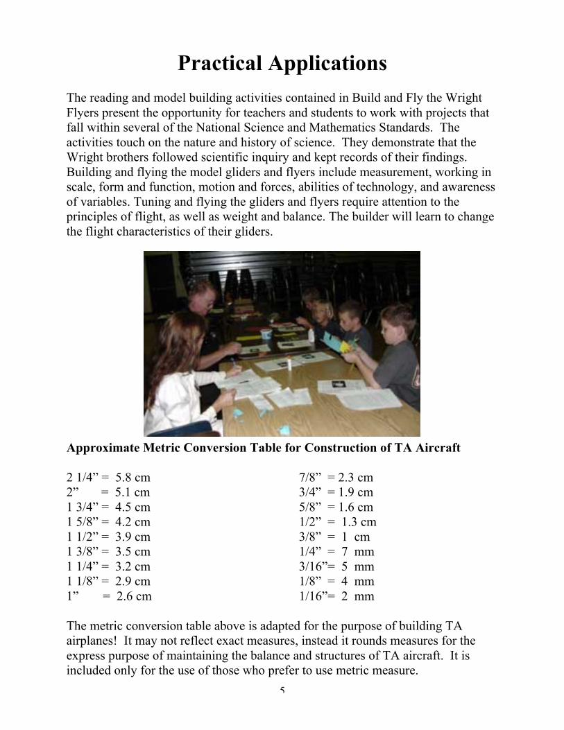
The reading and model building activities contained in Build and Fly the WrightFlyers present the opportunity for teachers and students to work with projects thatfall within several of the National Science and Mathematics Standards. Theactivities touch on the nature and history of science. They demonstrate that theWright brothers followed scientific inquiry and kept records of their findings.Building and flying the model gliders and flyers include measurement, working inscale, form and function, motion and forces, abilities of technology, and awarenessof variables. Tuning and flying the gliders and flyers require attention to theprinciples of flight, as well as weight and balance. The builder will learn to changethe flight characteristics of their gliders.
Approximate Metric Conversion Table for Construction of TA Aircraft
2 1/4” = 5.8 cm2” = 5.1 cm1 3/4” = 4.5 cm1 5/8” = 4.2 cm1 1/2” = 3.9 cm1 3/8” = 3.5 cm1 1/4” = 3.2 cm1 1/8” = 2.9 cm1” = 2.6 cm
7/8” = 2.3 cm3/4” = 1.9 cm5/8” = 1.6 cm1/2” = 1.3 cm3/8” = 1 cm1/4” = 7 mm3/16”= 5 mm1/8” = 4 mm1/16”= 2 mm
The metric conversion table above is adapted for the purpose of building TAairplanes! It may not reflect exact measures, instead it rounds measures for theexpress purpose of maintaining the balance and structures of TA aircraft. It isincluded only for the use of those who prefer to use metric measure.
6
7
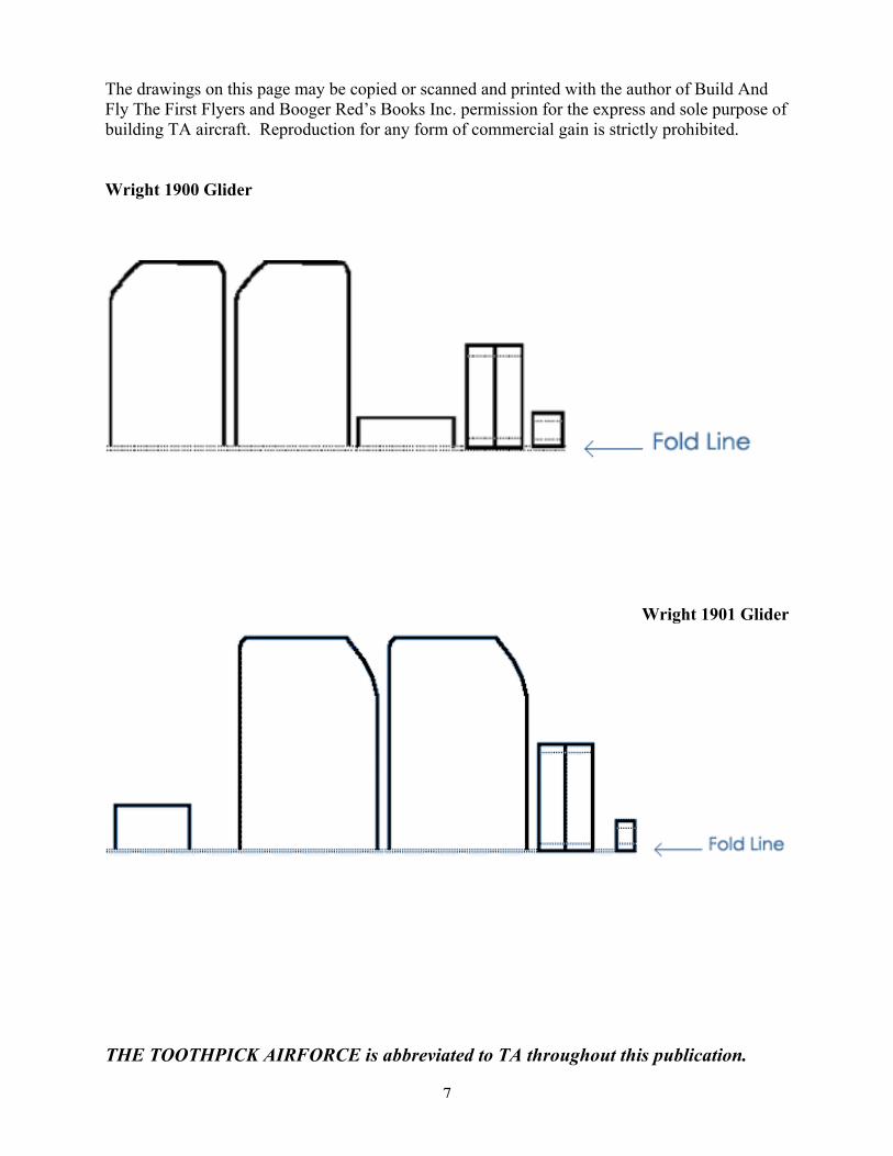
The drawings on this page may be copied or scanned and printed with the author of Build AndFly The First Flyers and Booger Red’s Books Inc. permission for the express and sole purpose ofbuilding TA aircraft. Reproduction for any form of commercial gain is strictly prohibited.
Wright 1900 Glider
Wright 1901 Glider
THE TOOTHPICK AIRFORCE is abbreviated to TA throughout this publication.
8
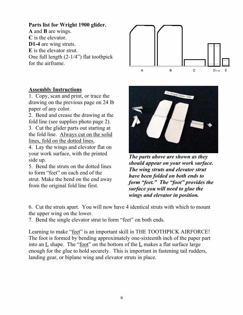
Parts list for Wright 1900 glider.A and B are wings.C is the elevator.D1-4 are wing struts.E is the elevator strut.One full length (2-1/4”) flat toothpickfor the airframe.
Assembly Instructions1. Copy, scan and print, or trace thedrawing on the previous page on 24 lbpaper of any color.2. Bend and crease the drawing at thefold line (see supplies photo page 2).3. Cut the glider parts out starting atthe fold line. Always cut on the solidlines, fold on the dotted lines.4. Lay the wings and elevator flat onyour work surface, with the printedside up.5. Bend the struts on the dotted linesto form “feet” on each end of thestrut. Make the bend on the end awayfrom the original fold line first.
The parts above are shown as theyshould appear on your work surface.The wing struts and elevator struthave been folded on both ends toform “feet.” The “foot” provides thesurface you will need to glue thewings and elevator in position.
6. Cut the struts apart. You will now have 4 identical struts with which to mountthe upper wing on the lower.7. Bend the single elevator strut to form “feet” on both ends.
Learning to make “feet” is an important skill in THE TOOTHPICK AIRFORCE!The foot is formed by bending approximately one-sixteenth inch of the paper partinto an L shape. The “foot” on the bottom of the L makes a flat surface largeenough for the glue to hold securely. This is important in fastening tail rudders,landing gear, or biplane wing and elevator struts in place.

9
The top wing should still be flat onyour work surface, print side up.Once the struts are in place and dry,straighten them up to a 90 degreeangle. Then line the wings up toglue them in position
Assembly Instructions (cont.)8. Smear a small amount of Elmer's(or similar paste) on each strut foot.Warning! Excessive amounts of paste
can cause warping of your wing surface. Mount them one at a time on the upperwing, beginning 1/4” from the centerline. Place the outside struts 3/8” from thewing tip, as shown in the photo.9. Examine your flat toothpick. You will find a slight bevel on both the wide andthe narrow ends of one side. Smear a small amount of glue on thesmall or narrow end of the toothpick on the non-beveled side. Press the toothpickinto position, overlapping the leading edge of the lower wing by 5/8”.
A 7/8” block from the large end ofa toothpick for weight glued to thetop of your toothpick airframeshould provide balance. Place it asfar forward as possible. Prepareyour glider to fly using the“tuning” instructions on the nextpage.
10. Straighten the wing struts to a 90 degree angle from the wing surface. Adjustthe feet on the opposite end of the struts so that the surface of the foot will contactthe bottom wing when it is lowered into position. Smear each of the four strutswith a small amount of glue, and carefully align the bottom wing with the top,gently pressing it into place.11. Glue the elevator strut 5/8” from the front of the airframe toothpick.12. Glue the elevator to the strut foot, so that the front of the elevator is 1/8 inchfrom the front of the toothpick fuselage.

10
Final Tuning For Wright Biplanes
Look at your TA Wright glider head on, andconcentrate on the wing. The wings areusually slightly warped because of the forceapplied to the paper when the wing is cut out.The sharper the scissors, the less warp youwill find.
When tuned, your aircraft shouldlook like the one above when viewedfrom the front. Only the leadingedge of the wing surface should bevisible.
If the wing surface is twisted orwarped, your aircraft will spin or turnto the left or right. Reducing thistwist or warp reduces drag, and willallow the aircraft to use the lift moreequally for the left and right wings.The goal is balance, or equal lift foreach wing surface.
The TA Wright ‘01 as it appears inthe “head on” view for tuning. Thisglider’s wings are warped in oppositedirections. The wing on the right iswarped up, while the left hand wingis warped down. Twist the wingsgently, in steps to equalize the lift onboth sides. Most Wright flyers needsome “up” elevator, as shown above.The tuning instructions on this pageapply to all Toothpick Airforceaircraft.
When tuning, continuously return to the head on view to observe the twist orwarp. Fly the aircraft in between to detect problems, or recognize when you haveachieved your goal. If the wing or wings are only slightly twisted, sometimes asimple twist in the opposite direction is all it takes.
The Wright 1900 and 1901 gliders had no tail rudders, or vertical stabilizersof any sort. The TA versions of these gliders are stabilized to good effect by thelateral surface area of the wing struts. While these can not be adjusted for yaw(turning), turns for these gliders can be achieved by wing warping, or adjustmentof one side or the other of the elevator.
Additional WeightAdding weight by increments of small lengths of toothpick can improve the
glide of your aircraft. While TA gliders can fly excellently with a little weight,sometimes more can make them fly better and faster. Use the elevator tocompensate for increased weight.

11
Wright 1901 GliderParts list for the 1901glider.A and B are wings.C is the elevator.D1-4 are wing struts.E1,2 are the elevatorstruts.Two full length toothpicksfor the airframe.
Assembly Instructions1. Copy, scan and print, or trace thedrawing on the previous page on 24 lbpaper of any color.2. Bend and crease the drawing at thefold line (see supplies photo p.2).3. Cut the glider parts out starting atthe fold line. Always cut on the solidlines, fold on the dotted lines.4. Lay the wings and elevator flat onyour work surface, with the printedside up.5. Bend the struts on the dotted linesto form “feet” on each end of thestrut. Make the bend on the end awayfrom the original fold line first.6. Cut the struts apart. You will nowhave 4 identical struts with which tomount the upper wing on the lower.Bend and cut the elevator struts apartthe same way.Caution, too much glue can warpand twist the wing!7. Smear a small amount of Elmer's(or similar glue) on each wing strut(D1-4) foot. Mount them one at a
Straighten the struts before mountingwing.
time on the upper wing, beginning1/4” from the centerline. Place theoutside struts 3/8” from the wing tip,as shown in the photo.8. Examine your flat toothpicks. Youwill find a slight bevel on both thewide and the narrow ends of one side.Smear a small amount of glue on thesmall or narrow end of each toothpickon the non-beveled side. Press thetoothpicks into position, overlappingthe leading edge of the lower wing by3/4” as shown in the photo above.

12
After the wing assembly is dry, gluethe elevator in place carefully. Two5/8” long blocks of toothpick fromthe wider, heavier end of a toothpickshould provide enough balanceweight. Consult “Final Tuning ForWright Biplanes” on page 10.
9. Straighten the wing struts to a 90degree angle from the wing surface.Adjust the feet on the opposite end ofthe struts so that the surface of thefoot will contact the bottom wingwhen it is lowered into position.Smear each of the four struts with asmall amount of glue and carefullyalign the bottom wing with the top,gently pressing it into place.Continue holding the wing in positionfor one minute, until the glue sets up.10. Glue the elevator struts in placeabout 1/2 inch from the front of theairframe.11. Smear a small amount of glue onthe top of the elevator struts, thenpress the elevator in place. Theelevator front should project forward3/8 inch in front of the elevator strut
12. Clip two 5/8 inch blocks of toothpick from the wider, heavier end of thetoothpicks, and glue them to the airframe in front of the elevator struts for balance.
A side by side comparison of the TA Wright 1900 and 1901 Wright gliders. Bothfly excellently even though the original Wright gliders did not! Do you knowwhy? One big reason is neither had upright tail or rudder surface. The 1902Wright glider had a single upright rudder located behind the wing.
13
Learning From the 1900 and the 1901 GlidersIn 1899 Wilbur and Orville Wright built and flew a kite with which to test
their first theories of control. The brothers had requested “all that is alreadyknown... about flying machines” from the Smithsonian and other sources.Focusing their attention on control and control surfaces as essential to mannedflight, they began a series of experiments. The new kite used wing warping toadjust for roll and turning, and an elevator to adjust for pitch.
The first experiments were successful, and the kite demonstrated it coulddive, climb, and roll to the right or left when directed by the operator. The brothersnow felt they were justified in turning their attention to a gliding machine capableof carrying a man.
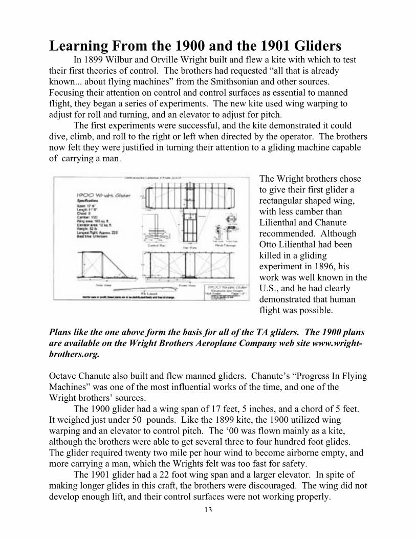
The Wright brothers choseto give their first glider arectangular shaped wing,with less camber thanLilienthal and Chanuterecommended. AlthoughOtto Lilienthal had beenkilled in a glidingexperiment in 1896, hiswork was well known in theU.S., and he had clearlydemonstrated that humanflight was possible.
Plans like the one above form the basis for all of the TA gliders. The 1900 plansare available on the Wright Brothers Aeroplane Company web site www.wright-brothers.org.
Octave Chanute also built and flew manned gliders. Chanute’s “Progress In FlyingMachines” was one of the most influential works of the time, and one of theWright brothers’ sources.
The 1900 glider had a wing span of 17 feet, 5 inches, and a chord of 5 feet.It weighed just under 50 pounds. Like the 1899 kite, the 1900 utilized wingwarping and an elevator to control pitch. The ‘00 was flown mainly as a kite,although the brothers were able to get several three to four hundred foot glides.The glider required twenty two mile per hour wind to become airborne empty, andmore carrying a man, which the Wrights felt was too fast for safety.
The 1901 glider had a 22 foot wing span and a larger elevator. In spite ofmaking longer glides in this craft, the brothers were discouraged. The wing did notdevelop enough lift, and their control surfaces were not working properly.

14
The drawings on this page may be copied or scanned and printed with the author of Build AndFly The First Flyers and Booger Red’s Books Inc. permission for the express and sole purpose ofbuilding TA aircraft. Reproduction for any form of commercial gain is strictly prohibited.
TA 1902 Wright Glider
TA Wright Kitty Hawk Flyer 1903

15
TA 1902 Wright Glider
Parts list for the TA 1902 WrightGlider.
A, B are wings.C1-4 are wing struts.D is the elevator.E1,2 are elevator struts.F Double tail rudder structure.G is the tail assembly top strap.Landing skids are full lengthtoothpicks.
Tail support is 7/8 of an inch long, from the small end of a toothpick.Lay the parts out with the printed side up on work surface.
Assembly Instructions1. Copy, scan and print, or trace the
drawings on the previous page on 24lb paper of any color.
2. Bend and crease the drawing at thefold line (supplies photo p 2).
3. Cut the glider parts out starting atthe fold line. Make the strut foldsfor the feet before cutting the strutsapart.
Build the 1902 Glider without camber!
4. Bending Toothpicks. For the next step select two similar flat toothpicks. Notall toothpicks have similar straightness, width, and thickness. Choose carefullybecause your aircraft will look and fly better.
Grasp the flat, wider end of one of the toothpicks, and bend it three-eights ofan inch from the end. When you hear and feel it crack, stop! We want the bentend to stay attached. We are building landing skids for your Wright glider. Bendthe second toothpick landing skid to match the first.
Bend the toothpick to a 45 degree angle or less and itwill be less likely to break off. If it breaks, try again.
Smear glue liberally on the top, bottom, and sides of both landing skids at thebend. The glue is to seal and strengthen the skid at the bend.

16
5. Glue the inside struts in place 1/4inch from the centerline, theoutside struts 3/4 inch from thewing tips. Always use a smallsmear of glue on wing struts asexcess amounts will warp the wingsurface.
6. Glue the toothpick landing skids1/4 inch from the centerline, at aright angle to the wing. When inposition, the trailing or small endof the skid should be 1/8 inch fromthe trailing edge of the wing.
See page 8 for making strut “feet.”The struts are positioned and gluedin place, the strut feet bent to rightangles from struts. The wings areupside down.
Lower the bottom wing into position,aligning it directly above the upperwing. Note tail assembly ready tohang.
7. Glue the tail support in place onthe centerline, extending to therear of the wing at a right angle,with a 1/8 inch overlap. Allowtime to dry.
8. Smear a small amount of glue onthe strut feet, and lower the bottomwing assembly into place as shownat left. Press gently on the bottomwing over the strut feet to insureproper bonding.
9. Hang the tail as shown below,gravity holds it in place
While the glider is upside down –smearglue on the tail support, hang the tailassembly on the tail support.
Glue the elevator struts in place 5/8inch from the leading edge of thewing.

17
Glue the elevator struts in place 5/8inch from the leading edge of thewing.
The Wright glider will need some“up” elevator. Bend the leadingedge upward, the rear edge down.
When Wilbur and Orville Wright built their 1902 glider, they had alreadybuilt a kite (1899), and flown their 1900 and 1901 gliders. They had studied otherpioneers’ efforts, and used a wind tunnel to perfect their design.
The 1902 Wright glider was the first aircraftever that had control over all three axes:yaw, pitch and roll. A single tail ruddercontrolled yaw, or right and left turns. Thisglider was first built with a double, non-steering rudder. The Wrights made almost1,000 glides with this aircraft duringSeptember and October of 1902. When thechange was made to a single, steer-ablerudder, their glide times increased. Wright 1902 glider.
The Wrights called the elevator, which they placed in front of the mainwings, a horizontal rudder. This “horizontal rudder” provided control over thepitch (up and down control) of their airplane.
Wilbur Wright discovered wing warping when he was able to visualize thetop and bottom surfaces of a bicycle inner tube box as wing surfaces. When oneend of the box was twisted down, the other end was twisted up. In this motion,Wilbur could envision the flight of birds and how to control roll. The bi-planedesign provided strength enough to make wing warping work, while the longer,thinner wings developed far more lift than the 1901 glider.
The Wright 1902 glider had a 32 foot wingspan and was 16.1 feet long. Itonly weighed 112 pounds. The Wrights continued using this glider in 1903, whilethey worked on the powered flyer. When the single rudder was replaced with adouble, steering rudder, they were able to increase their glide time again.
The ‘02 was the subject of the Wrights’ first and most important patent.

18
The First Powered Flight
On December 17, 1903, theWright brothers made four flightswith their first powered flyer at KittyHawk, North Carolina. On their bestflights, Orville flew about 120 feetand stayed aloft about 12 seconds.Wilbur managed to fly 852 feet andstayed in the air for 59 seconds.
The Wright brothers had toteach themselves to fly in briefseconds, in an airplane with controlsand control surfaces that were barelyadequate.
The dream comes true. Powered,controlled flight became reality onDecember 17, 1903, at Kitty Hawk,North Carolina
The Kitty Hawk flyer had a 40 foot 4 inch wingspan and was only a littleover 21 feet long. It weighed only 605 lbs. The Kitty Hawk flyer had twin tailrudders, and a 12 to 16 horsepower engine.
Although the first to actually fly, the Kitty Hawk flyer only made fourflights that day. It was damaged by wind after the fourth flight, and the Wrightspacked it up and shipped it back to Dayton, Ohio. Its flying days were over.
The Toothpick Airforce version of theWright Kitty Hawk flyer is the mostdifficult of the Wright replicas tobuild and fly. It has 21 paper parts,and at least five toothpick parts (youmay have to add weight). This glidermay take up to two hours to build, andrequires careful attention to detail inconstruction and tuning. Werecommend building at least one ofthe Wright gliders before attemptingthe Kitty Hawk flyer. “BendingToothpicks” instructions are found onpage 15.
Grasp your toothpick flyer by one ofthe landing skids, and thrust itforward gently. Add “up” elevatorby bending the leading edge of theelevator up and back.
19
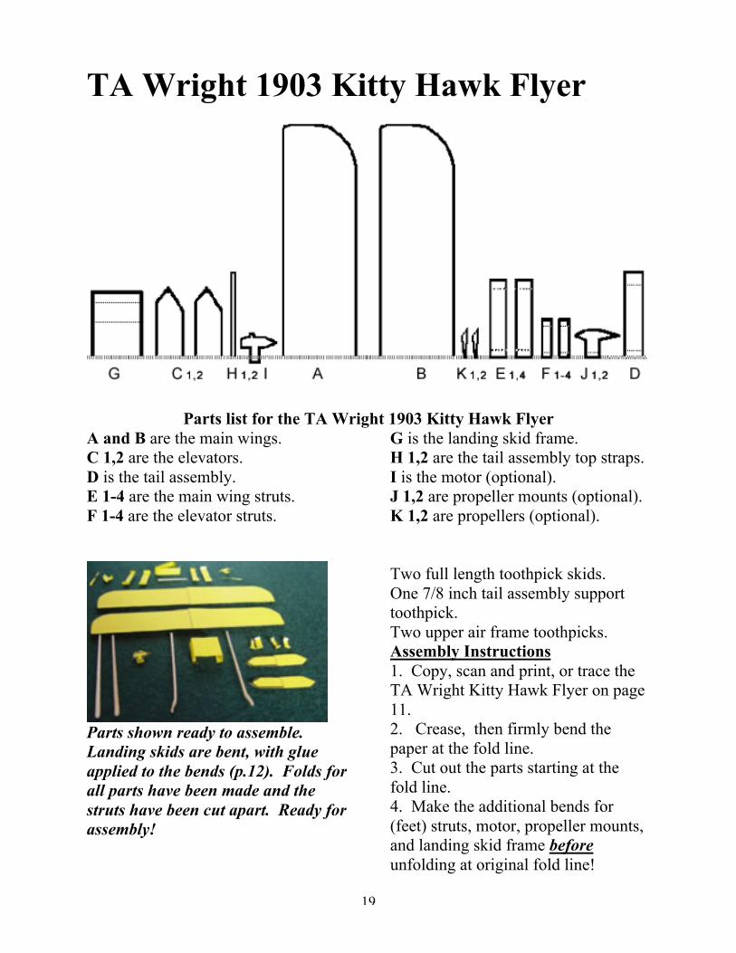
TA Wright 1903 Kitty Hawk Flyer
Parts list for the TA Wright 1903 Kitty Hawk FlyerA and B are the main wings.C 1,2 are the elevators.D is the tail assembly.E 1-4 are the main wing struts.F 1-4 are the elevator struts.
G is the landing skid frame.H 1,2 are the tail assembly top straps.I is the motor (optional).J 1,2 are propeller mounts (optional).K 1,2 are propellers (optional).
Parts shown ready to assemble.Landing skids are bent, with glueapplied to the bends (p.12). Folds forall parts have been made and thestruts have been cut apart. Ready forassembly!
Two full length toothpick skids.One 7/8 inch tail assembly supporttoothpick.Two upper air frame toothpicks.Assembly Instructions1. Copy, scan and print, or trace theTA Wright Kitty Hawk Flyer on page11.2. Crease, then firmly bend thepaper at the fold line.3. Cut out the parts starting at thefold line.4. Make the additional bends for(feet) struts, motor, propeller mounts,and landing skid frame beforeunfolding at original fold line!

20
Assemble the TA ‘03 Kitty Hawk Flyer
The TA Kitty Hawk Flyer flies a little better and is easier to build withoutthe engine and propeller assemblies. The ‘03 can be assembled with or withoutcambered wings. Read “Advanced Wing Structure” on page 24 before proceeding.The instructions assume you have completed the construction of prior gliders andgrasp concepts like “feet” and “Bending Toothpicks”.
5. Add camber to the wings now.Instructions for adding camber arefound on page 25.6. Place all paper parts with the printside up on your work surface. Gluethe inside struts in position 3/8 of aninch from the fold line, midwaybetween the leading and trailing wingedges of one wing. Glue the outsidestruts in position 3/4 of an inch fromthe wing tips, on line with the insidestruts. E 1-4 are wing struts.7. Place the second wing print side upon your work surface.
Bottom wing assembly is shown (attop), just below tail assembly,landing gear frame in place. Topwing assembly and elevator havestruts glued in place.
Select the landing skid frame (part G) and make the two folds along thedotted lines starting at the outside (away from the original fold line). Unfold part(G) on the original fold line, so that it will lay flat. Reverse the folds on theunprinted side of the landing skid frame. See the photo above.
Viewed from the front, part G should look like this.
Smear a little glue along the fold line in the center (on the bottom, or the sideaway from the print), and the outside edges of the landing skid frame (part G) andpress it in place on the bottom of the lower wing. The original fold line on thebottom of part G should be lined up with the original fold line on the lower wing,1/8 of an inch from the leading edge of the wing, as shown in the photo above.8. Smear a small amount of glue on two of the elevator struts (parts F 1-4) andglue them in position 1/4 inch from the fold line of one elevator (C 1,2).
Your wing and elevator assemblies should look like those in the photo above.

21
9. Smear glue on one side of the landing skid frame. Glue one of the landing skidsin place at a 90 degree or right angle to the bottom wing. The small (narrow) endof the landing skid should protrude 1/8 inch behind the skid frame. Glue thesecond skid into place, making them parallel to each other. Refer to the photobelow.10. Smear glue on the thicker end of the tail rudder support and glue it intoposition on the centerline at the trailing edge of the bottom wing assembly. Allbut 1/8 inch of the tail rudder support should protrude to the rear of the wingassembly. Allow this assembly to dry.
Smear glue on the strut feet, line thebottom wing up with the top, andpress it gently in place using the tailsupport to center one wing above theother.
11. Fold the tail assembly (D) into arectangular box by reversing the foldson one side of the assembly. The tailassembly and top straps (H1,2) areshown at the bottom right of the photoat the left.12. Glue the lower elevator on theupper elevator assembly (shownupside down in the photo at the left).13. If you choose to mount thepropeller assemblies and motor, gluethe propellers (K1,2) to the longprotrusion on the propeller mount(J1,2) as shown top left.
14. Smear glue lightly on the wing strut feet. The bottom wing assembly shouldbe lined up carefully, and lowered gently in position using the tail supporttoothpick as shown. It should be directly above the upper wing.
15. Pinch the end of the tail assembly(D) that has the original fold linegently, so that the fold line protrudes.Smear glue on the end of the tailsupport toothpick, and hang the tailassembly on the toothpick support asshown in the photo to the left.
When this assembly is dry, you areready for final assembly.
22
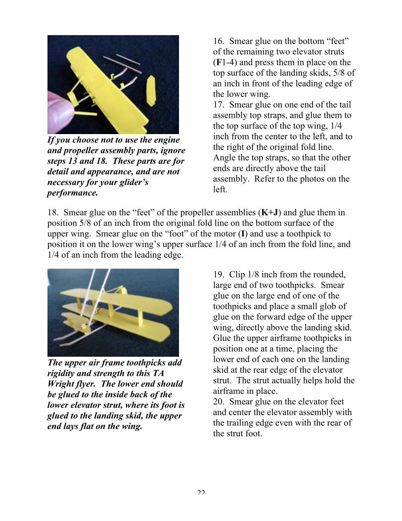
If you choose not to use the engineand propeller assembly parts, ignoresteps 13 and 18. These parts are fordetail and appearance, and are notnecessary for your glider’sperformance.
16. Smear glue on the bottom “feet”of the remaining two elevator struts(F1-4) and press them in place on thetop surface of the landing skids, 5/8 ofan inch in front of the leading edge ofthe lower wing.17. Smear glue on one end of the tailassembly top straps, and glue them tothe top surface of the top wing, 1/4inch from the center to the left, and tothe right of the original fold line.Angle the top straps, so that the otherends are directly above the tailassembly. Refer to the photos on theleft.
18. Smear glue on the “feet” of the propeller assemblies (K+J) and glue them inposition 5/8 of an inch from the original fold line on the bottom surface of theupper wing. Smear glue on the “foot” of the motor (I) and use a toothpick toposition it on the lower wing’s upper surface 1/4 of an inch from the fold line, and1/4 of an inch from the leading edge.
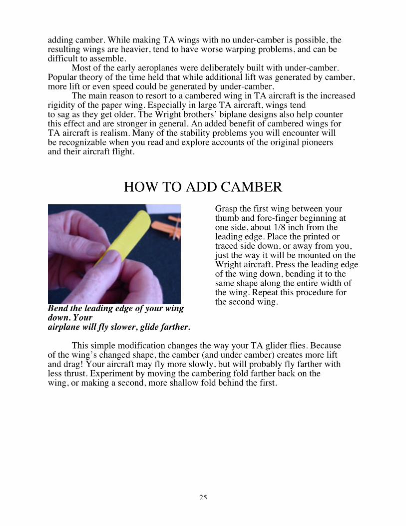
The upper air frame toothpicks addrigidity and strength to this TAWright flyer. The lower end shouldbe glued to the inside back of thelower elevator strut, where its foot isglued to the landing skid, the upperend lays flat on the wing.
19. Clip 1/8 inch from the rounded,large end of two toothpicks. Smearglue on the large end of one of thetoothpicks and place a small glob ofglue on the forward edge of the upperwing, directly above the landing skid.Glue the upper airframe toothpicks inposition one at a time, placing thelower end of each one on the landingskid at the rear edge of the elevatorstrut. The strut actually helps hold theairframe in place.20. Smear glue on the elevator feetand center the elevator assembly withthe trailing edge even with the rear ofthe strut foot.

23
21. Clip the ends off the toothpickairframe where it protrudes above thewing. If the glue comes loose fromthe wing,or the landing skid below,re-glue, using plenty of glue for thisapplication only. Allow the TA KittyHawk Flyer to dry before tuning.Line up the blades of the clippers sothat they strike squarely on thetoothpick, just above the wing.
22. Use a toothpick to slide a smear of glue under the rear of each tail assemblytop strap, then press them in place on the top of the elevator assembly. Make surethe tail assembly is lined up correctly, use the top straps to hold it in final position.The twin tail rudders should make your glider fly straight.
If you have questions or commentsregarding The Toothpick Airforce orthe gliders presented here, contactthe author at:
Or write to:
Booger Red’s Books Inc.P.O. Drawer GClifton, CO 81520
Final walk around on your new TAKitty Hawk Flyer: To add “up”elevator, gently bend entire structureto the rear.
Tune the TA Kitty Hawk Flyer by first examining the wings from the headon view. Gently adjust by twisting or bending the wing surfaces to provide equallift on each side. There will be some warping from the area the struts attach to, dueto the warping caused by gluing the two surfaces together.
Adjust the elevators to provide a slight lift and glide the aircraft by graspingone of the toothpick landing skids. More weight may be required. Add weight inshort lengths of toothpick, glued to the upper surface of the forward landing skids.
When tuned, the TA Kitty Hawk Flyer will glide 20 to 30 feet.

24
ADVANCED WING STRUCTURE
One of the Wright brothers’ major achievements was using a wind tunnel toanalyze how the shape of the wing affected the amount of lift the wing provided.They found that longer, narrower wings provided more lift and less drag. The bestwing shape the Wrights tested had a span six times its chord, or a 6:1 aspect ratio.In other words, for each inch of width, their wing had six inches of length. Thiswas the wing shape they used on almost all their flyers after 1902.
In addition, they discoveredthat the most efficient wing tested hadless camber than those used bypioneer gliding enthusiasts Lilienthaland Chanute. TheWrights used a camber of 1 in 20 (oneinch of rise for every 20 of chord)with the high point one fourth of thechord line from the leading edge ofthe wing. The Lilienthal wing had acamber of 1 in 12, with the high pointhalf way down the chord line.
The TA Kitty Hawk Flyer built withcambered wings flies farther, but alittle slower.
Adding camber to the wings of your Wright flyer takes a little time and a lotof patience, but will make your flyer more authentic as well as stronger.
The wing cross-section below shows how chord and camber are measured.
The chord of a wing is the measure of an imaginary line stretchingfrom the leading edge to the trailing edge.
The camber of a wing is its measure from the top curved surface tothat imaginary chord line. Most modern wings have both upper and lower camber.
The wing cross section above has under-camber. It is open on thebottom. A cambered wing produces more lift and is stronger. In TA aircraft,flat paper wings can be made stronger, and more like the original aircraft, by
25
adding camber. While making TA wings with no under-camber is possible, theresulting wings are heavier, tend to have worse warping problems, and can bedifficult to assemble.
Most of the early aeroplanes were deliberately built with under-camber.Popular theory of the time held that while additional lift was generated by camber,more lift or even speed could be generated by under-camber.
The main reason to resort to a cambered wing in TA aircraft is the increasedrigidity of the paper wing. Especially in large TA aircraft, wings tendto sag as they get older. The Wright brothers’ biplane designs also help counterthis effect and are stronger in general. An added benefit of cambered wings forTA aircraft is realism. Many of the stability problems you will encounter willbe recognizable when you read and explore accounts of the original pioneersand their aircraft flight.
HOW TO ADD CAMBER
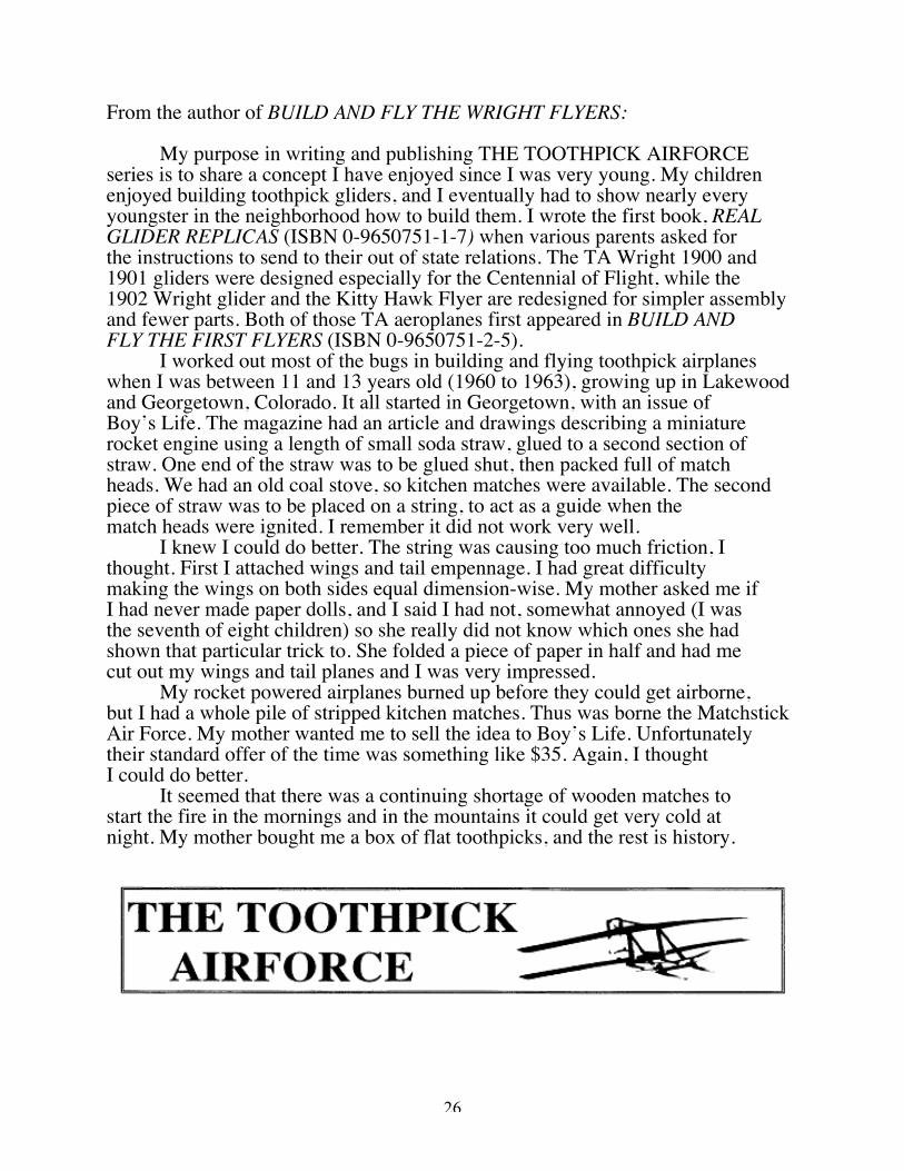
Bend the leading edge of your wingdown. Yourairplane will fly slower, glide farther.
Grasp the first wing between yourthumb and fore-finger beginning atone side, about 1/8 inch from theleading edge. Place the printed ortraced side down, or away from you,just the way it will be mounted on theWright aircraft. Press the leading edgeof the wing down, bending it to thesame shape along the entire width ofthe wing. Repeat this procedure forthe second wing.
This simple modification changes the way your TA glider flies. Becauseof the wing’s changed shape, the camber (and under camber) creates more liftand drag! Your aircraft may fly more slowly, but will probably fly farther withless thrust. Experiment by moving the cambering fold farther back on thewing, or making a second, more shallow fold behind the first.
26
From the author of BUILD AND FLY THE WRIGHT FLYERS:
My purpose in writing and publishing THE TOOTHPICK AIRFORCEseries is to share a concept I have enjoyed since I was very young. My childrenenjoyed building toothpick gliders, and I eventually had to show nearly everyyoungster in the neighborhood how to build them. I wrote the first book, REALGLIDER REPLICAS (ISBN 0-9650751-1-7) when various parents asked forthe instructions to send to their out of state relations. The TA Wright 1900 and1901 gliders were designed especially for the Centennial of Flight, while the1902 Wright glider and the Kitty Hawk Flyer are redesigned for simpler assemblyand fewer parts. Both of those TA aeroplanes first appeared in BUILD ANDFLY THE FIRST FLYERS (ISBN 0-9650751-2-5).
I worked out most of the bugs in building and flying toothpick airplaneswhen I was between 11 and 13 years old (1960 to 1963), growing up in Lakewoodand Georgetown, Colorado. It all started in Georgetown, with an issue ofBoy’s Life. The magazine had an article and drawings describing a miniaturerocket engine using a length of small soda straw, glued to a second section ofstraw. One end of the straw was to be glued shut, then packed full of matchheads. We had an old coal stove, so kitchen matches were available. The secondpiece of straw was to be placed on a string, to act as a guide when thematch heads were ignited. I remember it did not work very well.
I knew I could do better. The string was causing too much friction, Ithought. First I attached wings and tail empennage. I had great difficultymaking the wings on both sides equal dimension-wise. My mother asked me ifI had never made paper dolls, and I said I had not, somewhat annoyed (I wasthe seventh of eight children) so she really did not know which ones she hadshown that particular trick to. She folded a piece of paper in half and had mecut out my wings and tail planes and I was very impressed.
My rocket powered airplanes burned up before they could get airborne,but I had a whole pile of stripped kitchen matches. Thus was borne the MatchstickAir Force. My mother wanted me to sell the idea to Boy’s Life. Unfortunatelytheir standard offer of the time was something like $35. Again, I thoughtI could do better.
It seemed that there was a continuing shortage of wooden matches tostart the fire in the mornings and in the mountains it could get very cold atnight. My mother bought me a box of flat toothpicks, and the rest is history.

27