Embed Size (px)
Citation preview
Roadway and Roadside
Drainage
NEW YORK LTAP CENTER
Cornell Local Roads Program416 Riley-Robb Hall
Ithaca, New York 14853-5701phone: (607) 255-8033
fax: (607) 255-4080email: [email protected]
website: www.clrp.cornell.edu

Roadway and Roadside
Drainage
by David P. Orr, P.E.
Technical Assistance Engineer and Instructor
NEW YORK LTAP CENTER
Cornell Local Roads Program416 Riley–Robb Hall
Ithaca, New York 14853–5701phone: (607) 255–8033
fax: (607) 255–4080e–mail: [email protected]
web: www.clrp.cornell.edu
CLRP #98–5 updated February 2003


Acknowledgment The Cornell Local Roads Program would like to acknowledge the support and assistance of many people who helped put this manual together. An advisory committee of twelve individuals helped review topics, provide documentation and resources, and reviewed the draft of this workbook for content and flow. The advisory committee includes: David Orr, Technical Assistance Engineer, Cornell Local Roads Program (course instructor) Don Clarke, Superintendent of Highways, Village of Rushville Nelson Cook, Superintendent of Highways, Town of Palmyra Joe Lazenby, Superintendent of Highways, Village of Whitesboro Mark Redder, Superintendent of Highways, Town of Venice Toni Rosenbaum, Assistant Director, Cornell Local Roads Program Daniel Truesdail, Highway Foreman, Tioga County Ron Updike, Superintendent of Highways, Town of Enfield Kelly Whittemore, Superintendent of Highways, Town of Nichols Jerry Wilber, Chemung Supply Corporation, Elmira Kevin Wilder, Engineering Supervisor, Jefferson County Peter Wright, Senior Extension Associate, Agricultural & Biological Engineering Department, Cornell University Several of the Local Technical Assistance Program (LTAP) Centers, located in various states, contributed their resources and supplied technical information during the development of this manual. In addition, many other people provided photographs, materials for use in training and research of the topics, and offered advice on topics and issues facing highway departments in New York State. Thank you to all of those who helped. Background The principal author of this manual is David P. Orr, P.E.. He is currently the Technical Assistance Engineer with the Cornell Local Roads Program. Prior to coming to the program in January 1996, David worked for eight years at the Yates County Highway Department. His positions at Yates County included highway engineer, civil engineer, and deputy superintendent. He is a graduate of Cornell University with a B.S. in engineering and is a licensed engineer in New York State.
Cornell Local Roads Program i
Preface This workbook is intended to provide basic drainage information to people who fix roads in New York State. It does not, and cannot provide all of the information needed to maintain and construct drainage systems along our streets and roads. Such a manual would be several hundred pages thick and would collect dust on a shelf. Therefore, I have included some basic information to help people who build and maintain drainage systems in New York State. The emphasis of this publication is on open drainage systems. However, It still should provide valuable information to anyone who maintains any drainage system. The accompanying training session and this workbook are complementary. Some of the information in this workbook will not be discussed in depth, and some of the training will give details not included in the book. Both the workbook and the training system employ the KISS system: Keep It Simple Dave. I hope this workbook will help you as you read it and use it in the future. Please let me know what improvements can be made. They will be made if possible. Thank you.
ii Cornell Local Roads Program

Table of contents 1 Introduction.......................................................................................................................1 1.1 History .....................................................................................................................1 1.2 Extent of drainage problems ....................................................................................2 1.3 Understanding water movement ..............................................................................3 1.4 Kinds of highway drainage ......................................................................................4
2 Earth materials ..................................................................................................................5 2.1 Soils .........................................................................................................................5 2.2 Road materials .........................................................................................................6
3 Subsurface water...............................................................................................................9 3.1 Ability of water to be held by soil ...........................................................................9 3.2 Effects of excess subsurface water ........................................................................10 3.3 Free–draining layer (permeable base)....................................................................15
4 Subsurface drains ............................................................................................................17 4.1 What subsurface drains do .....................................................................................17 4.2 What subsurface drains do not do..........................................................................18 4.3 Underdrains vs. trench drains ................................................................................19 4.4 Installation .............................................................................................................20 4.5 Maintenance...........................................................................................................21
5 Cross section elements....................................................................................................23 5.1 Pavement................................................................................................................23 5.2 Shoulders ...............................................................................................................25 5.3 Base and subgrade .................................................................................................26 5.4 Driveways ..............................................................................................................28
6 Legal issues.....................................................................................................................29 6.1 Law ........................................................................................................................29 6.2 Rights and responsibilities .....................................................................................29 6.3 Right–of–way/easements .......................................................................................30 6.4 Permits and procedures ..........................................................................................33
7 Culverts ...........................................................................................................................35 7.1 Hydrology and hydraulics......................................................................................35 7.2 Materials, shapes, and sizes ...................................................................................40 7.3 What is the best type of pipe materials to use?......................................................43 7.4 Size and capacity ...................................................................................................44 7.5 Choosing pipe size .................................................................................................49 7.6 Planning a culvert replacement..............................................................................51 7.7 Installation .............................................................................................................53 7.8 Inspection...............................................................................................................56 7.9 Maintenance...........................................................................................................60
Cornell Local Roads Program iii

8 Ditches ............................................................................................................................63 8.1 Purposes .................................................................................................................63 8.2 Shapes ....................................................................................................................64 8.3 Side slopes .............................................................................................................65 8.4 Fall .........................................................................................................................66 8.5 Lining materials .....................................................................................................66 8.6 Capacity and depth.................................................................................................67 8.7 Maintenance...........................................................................................................68 8.8 General tips ............................................................................................................69
9 Slopes and erosion control ..............................................................................................71 9.1 How to stop erosion ...............................................................................................71 9.2 Types of erosion.....................................................................................................71 9.3 Sedimentation ........................................................................................................72 9.4 Slopes.....................................................................................................................72 9.5 Erosion mitigation..................................................................................................74 9.6 Maintenance...........................................................................................................75 APPENDICES A Culvert Inspection...........................................................................................................77
B Temporary Easement ......................................................................................................78
C Bibliography ...................................................................................................................79
D Resources ........................................................................................................................82
E NYSDOT Regional Offices ............................................................................................83
F NYS Soil and Water Conservation Districts...................................................................84
G Glossary ..........................................................................................................................85
iv Cornell Local Roads Program

List of figures 1 Rural road in the early 1900s............................................................................................2 2 Conceptual road drainage system .....................................................................................3 3 Roadway vs. roadside drainage ........................................................................................4 4 Sieve analysis....................................................................................................................5 5 Classification chart ...........................................................................................................7 6 Ice lenses.........................................................................................................................11 7 Winter “settling” due to frost heave ...............................................................................12 8 Thawing of pavement creating spring time bathtub .......................................................14 9 Draining thawing base (one side with underdrain, one with daylight)...........................14 10 Free–draining layer .........................................................................................................15 11 Interceptor drains ............................................................................................................17 12 Edge drains (underdrains) ...............................................................................................18 13 Drains with pipe, fins, sand, fabric .................................................................................20 14 Good and bad openings ..................................................................................................20 15 Cross slope ......................................................................................................................23 16 Bathtub construction .......................................................................................................27 17 How to fix bathtub base ..................................................................................................27 18 Use of swale or intercepting drain to provide positive drainage ....................................28 19 Temporary easement.......................................................................................................32 20 Dig Safely telephone number in New York State...........................................................33 21 One–call telephone number in New York City and Long Island ...................................33 22 Precipitation and runoff (hydrograph) ............................................................................36 23 Area of watershed USGS map.........................................................................................37 24 Pick a card.......................................................................................................................38 25 Pipe shapes (metal) .........................................................................................................41 26 Pipe shapes (plastic)........................................................................................................41 27 Pipe shapes (concrete) ....................................................................................................42 28 Pipe shapes (steel)...........................................................................................................42 29 Settlement due to poor joints ..........................................................................................43 30 Factors determining flow capacity of a pipe...................................................................44 31 12" vs. 24" pipe...............................................................................................................44 32 Shape of openings ...........................................................................................................45 33 Inlet (outlet) designs (projecting, mitered, and headwall) ..............................................46 34 Corrugated pipe end section ...........................................................................................47 35 Spacing between pipes....................................................................................................48 36 Multiple streams feeding a single culvert that needs to be replaced ..............................50 37 Natural vs. artificial alignments......................................................................................51
Cornell Local Roads Program v
38 Expressing alignment using offset ..................................................................................52 39 Cover and depth ..............................................................................................................52 40 How to calculate length of the pipe ................................................................................53 41 Staking roadway culvert .................................................................................................54 42 Bedding of pipes .............................................................................................................55 43 Minimum width of trench ...............................................................................................56 44 Culvert inspection ...........................................................................................................57 45 Debris catcher .................................................................................................................59 46 Scour, at end of pipe .......................................................................................................61 47 Scour repair.....................................................................................................................61 48 Ditch shapes ....................................................................................................................64 49 Changes in slope in a ditch cleaned at the same offset ...................................................65 50 Good check dam showing deep bedding and downstream pad ......................................66 51 Ditch versus pipe area.....................................................................................................68 52 Types of erosion..............................................................................................................72 53 Slopes..............................................................................................................................72 54 Placement of rip–rap on a slope......................................................................................74 55 Placement of an erosion fabric to protect a slope ...........................................................75
vi Cornell Local Roads Program
List of tables 1 Miles of road and streets maintained by local governments in New York State..............2 2 Soil classes and sizes ........................................................................................................5 3 Gradations of gravels for roads.........................................................................................7 4 Height of capillary rise .....................................................................................................9 5 Permeability rates (typical) .............................................................................................10 6 Frost–susceptible soils ....................................................................................................12 7 General repairs ................................................................................................................24 8 Shoulders (materials and types) ......................................................................................26 9 Coefficient of runoff (table of values) ............................................................................37 10 Design year for various road types and drainage items ..................................................39 11 Runoff from two watersheds using different analyses....................................................39 12 Ditch lining materials......................................................................................................67
List of boxes 1 Stabilization of base and surface gravels..........................................................................8 2 Alleviating winter settling due to frost heave.................................................................12 3 Backfilling subsurface drains..........................................................................................19 4 Determining right–of–way..............................................................................................31 5 50–year storm..................................................................................................................38 6 Diameter versus area.......................................................................................................44 7 Compaction and trench width .........................................................................................56
Cornell Local Roads Program vii


Drainage:
The process of removing and controlling excess surface and subsurface water to help maintain roads and streets.
1 - INTRODUCTION 1.1 HISTORY In the late 1800s, roads in the United States were, to be honest, poor. To a large extent, they lacked proper construction, maintenance, and drainage. The year 1880 saw the creation of a group that helped to change the conditions of roads in this country, the League of American Wheelmen, an association of bicycle riders! The League’s efforts eventually led to the creation of the U.S. Office of Road Inquiry in the Department of Agriculture in 1893. By 1904, about 7 percent of the roads in the U.S. were “improved”. Improved meant gravel, graded and smoothed, not blacktop. With the advent of the Rural Free Delivery mail and the increase in the use of cars, more pressure was placed on government to build better roads and highways. The Good Roads movement in the early 1900s kept pressure on government and led to the 1916 Federal–Aid Road Act, a nationwide effort to “get the farmer out of the mud”. This bill is the direct ancestor of the Transportation Equity Act for the 21st Century (TEA21), today’s federal program for highways and streets. While the condition of roads has greatly improved since the early part of the century when the United States was considered 50 years behind the rest of the industrial world, we still have a long way to go. Many of those problems are drainage related.
Cornell Local Roads Program 1
Roadway & Roadside Drainage
1.2 EXTENT OF DRAINAGE PROBLEMS Highway agencies spend more than 25 percent of their budget on drainage. Typical problems caused by poor drainage include:
• Rutting • Cracking • Potholes • Erosion • Washouts • Heaving • Flooding
Together or alone, these defects will lead to premature failure of roadway
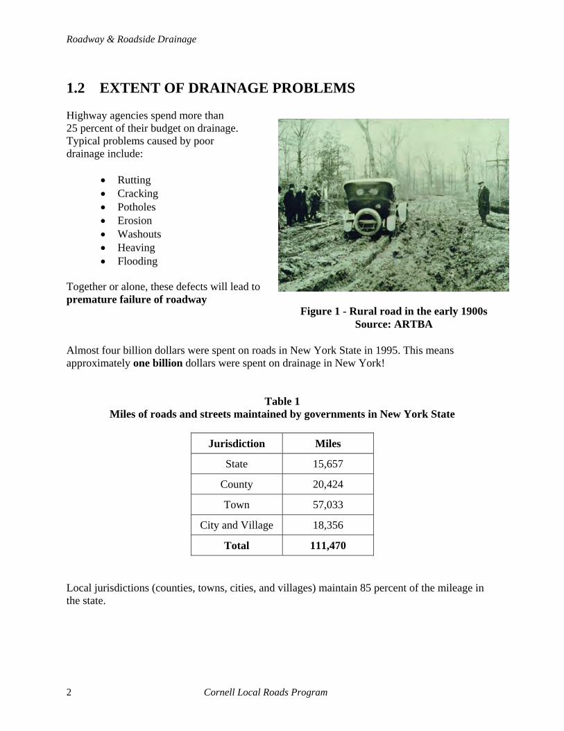
Figure 1 - Rural road in the early 1900s Source: ARTBA
Almost four billion dollars were spent on roads in New York State in 1995. This means approximately one billion dollars were spent on drainage in New York!
Table 1 Miles of roads and streets maintained by governments in New York State
Jurisdiction Miles
State 15,657
County 20,424
Town 57,033
City and Village 18,356
Total 111,470
Local jurisdictions (counties, towns, cities, and villages) maintain 85 percent of the mileage in the state.
2 Cornell Local Roads Program

1 - Introduction
1.3 UNDERSTANDING WATER MOVEMENT
ground water table
ditchunderdrain
outlet pipe
culvert outlet
daylighted base
pavement shoulder
capillary moistureside infiltration
infiltration through cracks and defects
Rain & Snow
Figure 2 - Conceptual road drainage system
1.3.1 Hydrologic cycle Rain and snow falling on the ground will run overland or soak into the ground. Eventually all the runoff will reach lakes, streams, or the ocean where the water will evaporate and start the cycle all over again.
1.3.2 Water movement around roads When maintaining and building roads and streets, we must be concerned with water flowing around them. Figure 2 shows a conceptual drainage system and how water may enter a road. Water may enter roadways through “cracks and surface defects” on the pavement. Or it can “infiltrate from the side” through the fill. “Capillary action” may draw moisture up from the water table and cause the base to become saturated. “Excess water” in ditches and flowing through culverts can cause damage to roads by causing washouts and failure of storm water systems, slope instability, and erosion.
Cornell Local Roads Program 3
Roadway & Roadside Drainage
1.4 KINDS OF HIGHWAY DRAINAGE
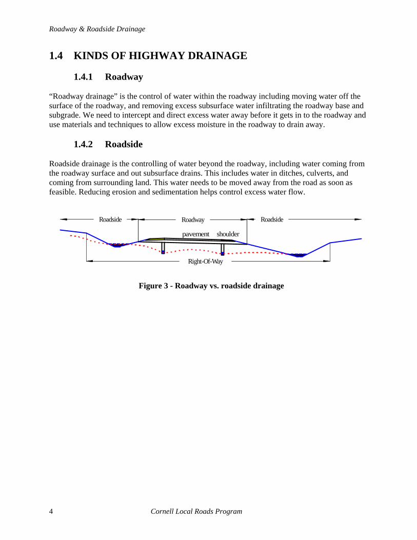
1.4.1 Roadway “Roadway drainage” is the control of water within the roadway including moving water off the surface of the roadway, and removing excess subsurface water infiltrating the roadway base and subgrade. We need to intercept and direct excess water away before it gets in to the roadway and use materials and techniques to allow excess moisture in the roadway to drain away.
1.4.2 Roadside Roadside drainage is the controlling of water beyond the roadway, including water coming from the roadway surface and out subsurface drains. This includes water in ditches, culverts, and coming from surrounding land. This water needs to be moved away from the road as soon as feasible. Reducing erosion and sedimentation helps control excess water flow.
pavement shoulder
RoadwayRoadside Roadside
Right-Of-Way
Figure 3 - Roadway vs. roadside drainage
4 Cornell Local Roads Program

2 - Earth Materials
2 - EARTH MATERIALS Roads are built on top of native soils. Earth materials and aggregates (gravels) are used to build and construct roads. Good drainage starts with using the correct materials to construct the base of a road. Understanding some properties of the materials we use to build roads will make our jobs easier. More information on earth materials is available in the Cornell Local Roads Program manual, Basics of a Good Road. 2.1 SOILS Soils are classified by their size into four general categories. Soil analysis starts by classifying soils by the percentage of each size material they contain. We need to know the amount of each category of material in an aggregate to determine if it is suitable for building a road.
Table 2 Soil classes and sizes
Soil types Size (mm) Sieve sizes
Boulders & cobbles >75 mm Retained on the 75 mm (3") sieve
Gravel 2.0 to 75 mm Retained on the #10 sieve
Sand 0.075 to 2.0 mm Retained on the #200 sieve
Fines (silt & clay) <0.075 mm Passes the #200 sieve
Boulders and cobbles are very large and should not be used in the base and surface of roads. They are very useful for erosion control, scour protection and filling gabions. Gravel particles are large and have high strength. Due to their importance in providing strength, we refer to the mixture of particles used to build roads as gravel. Sands drain very well and are relatively stable. They fill the voids between gravel particles. Fines (silts and clays) have the smallest size particles. Clay soils are hard when dry, but very soft when wet. Clays feel greasy when wet. Silts are slightly larger and will erode very easily. Fines provide no strength. Their primary purpose in gravels is to help bind together surface materials exposed to traffic.
Figure 4 - Sieve analysis
Cornell Local Roads Program 5

Roadway & Roadside Drainage
A simple test can be performed in a lab or in the field in approximately 30 minutes. The Sand Equivalent Test measures the proportion of clay-like particles in the sand size and smaller particles of a gravel. A sample of material is placed in a cylinder with a special solution and let to soak. It is then shaken and the sand particles settle out almost immediately. After twenty minutes the clay-like particles have settled to some value in the cylinder (Clay reading). The sand particles, which can support a weight, have settled to a lower value (Sand reading). The ratio of these two lines, reported as a percentage, is the Sand Equivalent. For more information, request the Gravel Series (three newsletter articles) from the Cornell Local Roads Program. 2.2 ROAD MATERIALS We build roads with earth materials that are a mixture of different size materials as listed above. Gravels and aggregates used to build roads should be clean, hard, durable, angular, and not susceptible to damage due to freezing and thawing. The strength and quality of the gravel is directly related to the gradation or mixture of different size particles. Gravel particles are needed for their strength and durability. Sand size particles are needed to fill the voids between the gravel particles and help stabilize the aggregate. Some fine particles are needed with surface gravels to bind the gravel together and help eliminate dust problems.
2.2.1 Surface gravels The material used for the surface of a gravel road needs to have slightly more fines than a base gravel to help hold the particles in place during dry periods. Without enough fines, traffic will cause the material to ravel and washboard. On the other hand, excessive fines will cause the surface to be too soft during spring thaw. Ruts and other depressions during spring thaw are often due to excessive fines in the surface and base.
2.2.2 Base The material below the surface of a road whether it is paved or not is the base. The materials in the base of the road should be clean (very few fines). A material that is good as a surface gravel will NOT be a good material for the base of a roadway. A good base will be free draining and have a high permeability. Excess fines will hold moisture, and the base will be weaker than it should. The following table and figure show the recommended gradations for materials used in road building.
6 Cornell Local Roads Program

2 - Earth Materials
Table 3 Gradations of gravels for roads
Percentage of materials
Soil type SURFACE BASE
Notes
Cobbles 0% 0% No material larger than 3" should be used
Gravel 50 - 70% 50 - 70% Same for both surfaces and bases
Sand 25 - 40% 25 - 40% Same for both surfaces and bases
Fines 8 - 15% 0 - 8% More fines needed in a surface gravel Note: The amount of gravel and sand is the same for both base and surface materials. The fines are needed on the surface to bind the material together. The fines do nothing to help the strength of the material. If placed below a surface where evaporation cannot occur, the gravel will be too soft and premature failure will occur.
-100
-90
-80
-70
-60
-50
-40
-30
-20
-10
- 0
0-
10-
20-
30-
40-
50-
60-
70-
80-
90-
100-
0- 10- 20- 30- 40- 50- 60- 70- 80- 90- 100-
% SA
ND
% SILT & CLAY
% G
RAV
EL
Bases
Surfaces
Figure 5 - Classification chart
Cornell Local Roads Program 7
Roadway & Roadside Drainage
Naturally occurring materials have a tremendous variation in gradation. Only a small amount of natural material is suitable for use in roads and streets.
2.2.3 Subgrade The subgrade is just a fancy name for the native material we build the roadway on after we have removed any topsoil. The objective of any road construction is to build a road that does not overstress the subgrade. For drainage, we need to be concerned about the water carrying capability of the subgrade and the height of the water table within it. Also, we need to make sure the surface of the subgrade can drain before placing material on top of it.
Box 1 - Stabilization of base and surface gravels
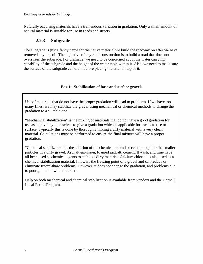
Use of materials that do not have the proper gradation will lead to problems. If we have too many fines, we may stabilize the gravel using mechanical or chemical methods to change the gradation to a suitable one. “Mechanical stabilization” is the mixing of materials that do not have a good gradation for use as a gravel by themselves to give a gradation which is applicable for use as a base or surface. Typically this is done by thoroughly mixing a dirty material with a very clean material. Calculations must be performed to ensure the final mixture will have a proper gradation. “Chemical stabilization” is the addition of the chemical to bind or cement together the smaller particles in a dirty gravel. Asphalt emulsion, foamed asphalt, cement, fly-ash, and lime have all been used as chemical agents to stabilize dirty material. Calcium chloride is also used as a chemical stabilization material. It lowers the freezing point of a gravel and can reduce or eliminate freeze-thaw problems. However, it does not change the gradation, and problems due to poor gradation will still exist. Help on both mechanical and chemical stabilization is available from vendors and the Cornell Local Roads Program.
8 Cornell Local Roads Program
3 - SUBSURFACE WATER Water within the surface, base, and subgrade materials of a roadway is subsurface water. Some water will always be present and may actually be beneficial by helping to hold together the soil particles. However, excess subsurface water will cause a lot of damage to a roadway. Several factors affect the ability of soil to carry and allow infiltration of subsurface water. 3.1 ABILITY OF WATER TO BE HELD BY SOIL Fines (silts and clays) hold water within soil in the same way water is held by a sponge. The higher the fines content, the more water held by the soil. Water held within the soil due to the presence of fines will not be removed by the force of gravity. Underdrains and daylighting dirty bases will not keep them dry. Use of clean materials is absolutely critical to keep soils dry and strong.
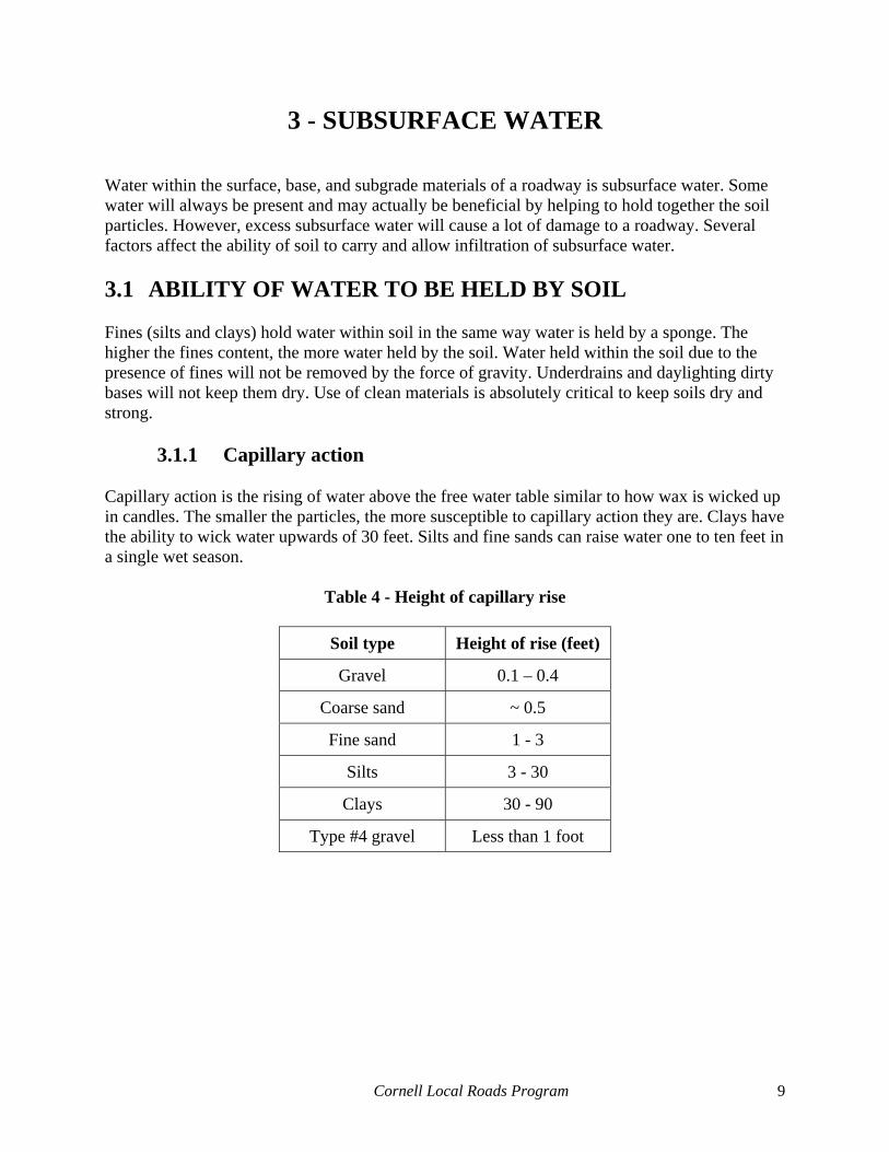
3.1.1 Capillary action Capillary action is the rising of water above the free water table similar to how wax is wicked up in candles. The smaller the particles, the more susceptible to capillary action they are. Clays have the ability to wick water upwards of 30 feet. Silts and fine sands can raise water one to ten feet in a single wet season.
Table 4 - Height of capillary rise
Soil type Height of rise (feet)
Gravel 0.1 – 0.4
Coarse sand ~ 0.5
Fine sand 1 - 3
Silts 3 - 30
Clays 30 - 90
Type #4 gravel Less than 1 foot
Cornell Local Roads Program 9

Roadway & Roadside Drainage
3.1.2 Permeability The ability of water to pass through a soil is known as permeability. Gravels and sands have high permeabilities. Clays and silts act as barriers to the movement of water. They have very low permeability. If we are trying to drain soils, the presence of clays and silts will greatly hamper our effort to remove the water.
Table 5 - Permeability rates (typical)
Soil type Rate (feet/day)
Gravel 2,500 – 25,000
Sand 10 – 25
Silts 0.025 – 2.5
Clays 0.00001 – 0.025
Type #4 gravel ~ 50
3.2 EFFECTS OF EXCESS SUBSURFACE WATER
3.2.1 Frost Action (heaving) Frost heave is a major problem in New York State or wherever freezing temperatures occur for prolonged periods. Heaving occurs when there are:
• Freezing temperatures • Free water available to create ice lenses • Frost–susceptible soils present
All three must be present to have frost heaving. Since we cannot control the weather, we usually concentrate on eliminating the source of free water or using non–frost susceptible soils.
10 Cornell Local Roads Program

3 - Subsurface Water
Frost Susceptible Soil
Pavement
Base Course
Free Watertable
Freezing Front
Moisture Migration
Freezing Temperatures
Pavement
Base Course
Frost Susceptible Soil
. Frost heave
Frost Susceptible Soil
Pavement
Base Course
Free Watertable
Freezing Front
Moisture Migration
Freezing Temperatures
Pavement
Base Course
Frost Susceptible Soil
. Frost heave
SPRING–FALL WINTER
Figure 6 - Ice lenses
Figure 6 shows the effects of frost heaving. Free water is drawn up by capillary action. As the ground freezes from above, a line between the frozen ground above and the unfrozen ground below (freezing front) moves down. Where the freezing front interacts with water drawn up by capillarity, ice lenses grow. As the front moves down, additional lenses grow and the ground heaves. In the spring, thawing occurs from the top down. Any excess moisture trapped in ice lenses will cause the pavement to be excessively weak. It is critical that we do not use frost-susceptible soils in our bases and surfaces. Frost-susceptible materials are prone to more problems and will be weaker in the spring. Eliminating the source of free water is done by use of intercepting drains, trench drains, or intercepting ditches. Lowering the water table by use of underdrains is of limited effectiveness due to the high level water can be raised from capillary action. Frost-susceptible soils are ones that have both high capillarity and permeability. Clays are not as frost susceptible as silts, but are very weak when wet. They have a high capillary action but pull water so slowly that by the time enough water has been pulled through them to create ice lenses, it is spring. Silts are very susceptible to frost heaving. Gravels and sands are the best materials to use to eliminate the problems of frost heaving. We cannot typically replace the subgrade (native materials) but we MUST use non-frost susceptible materials in our bases to help reduce problems.
Cornell Local Roads Program 11

Roadway & Roadside Drainage
Table 6 - Frost-susceptible soils
Frost susceptibility Soil types
Low Clean gravels and washed sands
Medium Unwashed sands with moderate amounts of silty fines
High Dirty gravels and pure clays
Very high Silts and silty materials (including most materials called clay in New York State)
Note: We cannot eliminate frost heaving subgrades, but we can build roads on them with the use of clean, high quality materials.
Box 2 - Alleviating sinter settling due to frost heave
One note of caution must be made when we make roadway repairs. Every winter a few culverts seem to “sink” or “settle”. Many of these culverts were actually compacted with non–frost susceptible materials, and the roadway around them is just heaving up to make them seem lower. When backfilling pipes, we should reuse the material, if possible, in the trench around the pipe to help alleviate this problem. If we use a non–frost susceptible material around the culvert, it does not heave in the winter. As the road on either side heaves, the culvert appears to settle.
Figure 7 Winter “settling” due to frost heave
Pavement
Base Course
Free Watertable
Frost SusceptibleSoil
Freezing Front
Moisture Migration
Freezing Temperatures
.Pipe "Settlement"
Non-frost Susceptible
Culvert
Pavement
Base Course
Free Watertable
Frost SusceptibleSoil
Freezing Front
Moisture Migration
Freezing Temperatures
.Pipe "Settlement"
Non-frost Susceptible
Culvert
12 Cornell Local Roads Program

3 - Subsurface Water
3.2.2 Pumping Pumping is the mixing of layers of soil due to the vibration and loads of traffic. Especially during wet periods, the loads of traffic can cause the soil of the subgrade to be pushed or pumped into the base gravel. If the amount of fines pumped into the base is too great, the material will become weak and fail prematurely. Use of a separation fabric or sand filter layer between the native soil and the base of the roadway will eliminate most of this problem.
3.2.3 Potholes Potholes are formed by the interaction of excess water, traffic, and weak materials. Excess water is the most significant culprit. Good materials may still form potholes if excess moisture is present. Potholes form when the lower layers, softened by excess water, do not provide strength to the pavement above. The surface layer is overstressed and cracks or softens. Traffic pushes this weak material away and potholes are formed. Since we cannot stop traffic and even good materials will eventually pothole, we must eliminate excess moisture by use of free draining bases and interception drains.
3.2.4 Spring thaw Spring thaw is when we get to harvest our most famous crop, potholes. Roads thaw from the top down. Also, the shoulders may remain frozen while the roadway had thaws. This is especially true if the materials in the shoulder have a higher fine content than the base under the road. When this happens, spring thaw is worse than a typical rainy period. With an unfrozen layer over the frozen base and the shoulders frozen, the road acts like a bathtub. If we do not allow for the water to drain with underdrains or daylighted bases, the saturated soils will be much weaker than they should be and will fail much sooner. Posting roads to restrict heavy vehicles may be necessary to keep roads from failing during the spring thaw period. Roads should be posted for as short a period as possible. Tire pressure restrictions have been used by some agencies to help reduce damage to rural roads.
Cornell Local Roads Program 13

Roadway & Roadside Drainage
CLpavementshoulder
The thawing of the roadbed in the spring occurs from the top down and usually starts under the center of the roadway. The shoulders stay frozen and trap water in the base and subgrade. This saturated material is very weak and fails prematurely. Removal of the excess water can be done by either daylighting the base (the daylighted material thaws faster than a dirty material) or installing subsurface drains to help remove the free water.
Figure 8 - Thawing of pavement creating spring time bathtub
Figure 9 - Draining thawing base (one side with underdrains, one with daylight)
BaseVery wet (saturated) thawed soil
Unfrozen soil
Frozen soil
CLpavementshoulder
BaseVery wet (saturated) thawed soilFrozen soil
Unfrozen soil
CLpavementshoulder
BaseVery wet (saturated) thawed soil
Unfrozen soil
Frozen soil
CLpavementshoulder
BaseVery wet (saturated) thawed soilFrozen soil
Unfrozen soil
14 Cornell Local Roads Program
3 - Subsurface Water
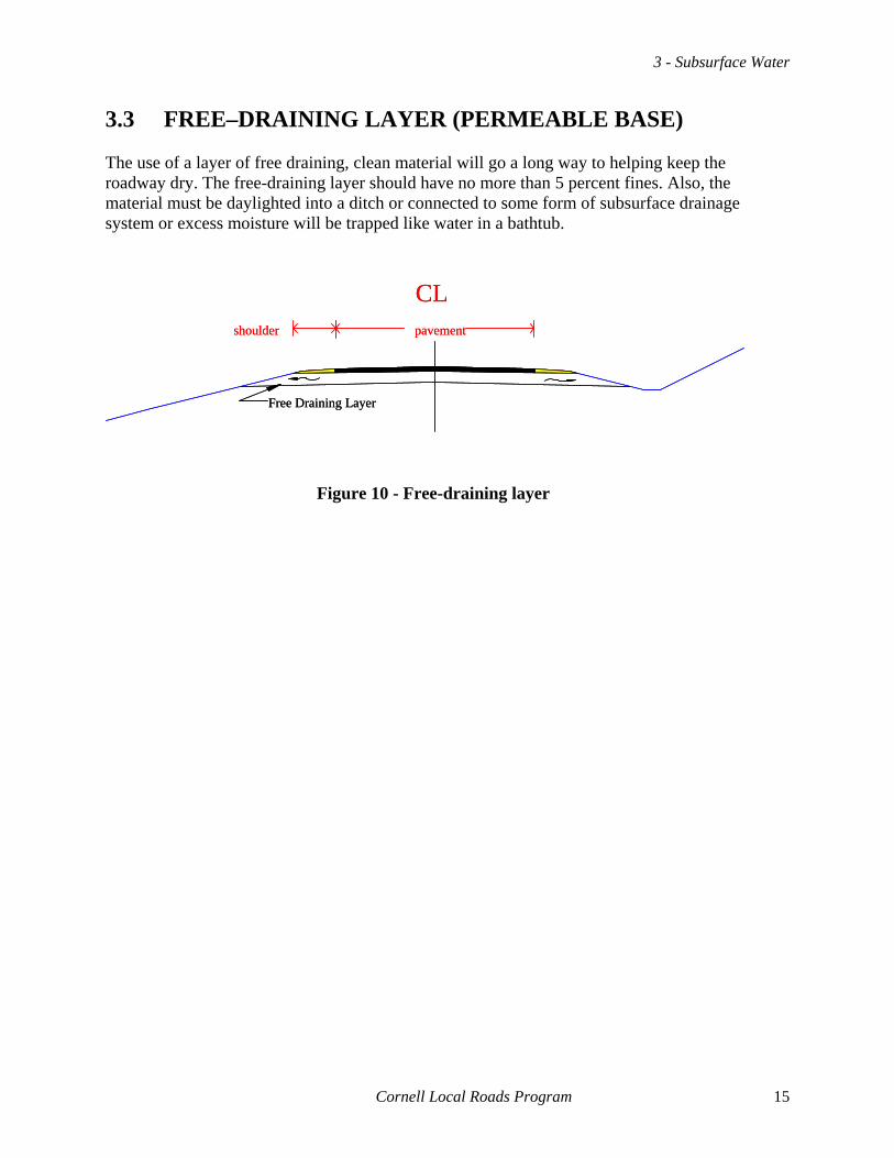
3.3 FREE–DRAINING LAYER (PERMEABLE BASE) The use of a layer of free draining, clean material will go a long way to helping keep the roadway dry. The free-draining layer should have no more than 5 percent fines. Also, the material must be daylighted into a ditch or connected to some form of subsurface drainage system or excess moisture will be trapped like water in a bathtub.
Free Draining Layer
CLpavementshoulder
CLpavementshoulder
Free Draining Layer
Figure 10 - Free-draining layer
Cornell Local Roads Program 15


4 - Subsurface Drains
4 - SUBSURFACE DRAINS Subsurface drains, including underdrains and trench drains, are not miracle workers. They do three things: intercept water before it gets to the road, lower the water table, and remove excess free moisture. There are lots of claims made about what subsurface drains can do. All of the items which subsurface drains do fall into one of these categories. 4.1 WHAT SUBSURFACE DRAINS DO
4.1.1 Interception Subsurface drains can keep water from getting to a roadway. This is most critical in cut or side hill sections where high water tables provide a large amount of water trying to get to the base of the roadway. When we install a base of gravel, the gravel will, typically, allow more water through it than the surrounding soils. If there is any pressure to the subsurface water, the water will come out in the road and cause the materials in the road to weaken. In a side hill section, if the materials become too wet, they may slide and cause a roadway failure.
Seepage Layer
Impervious LayerSeepage interceptedwater tale before draining
CLpavement original groundshoulder
CLpavement original groundshoulder
Seepage LayerSeepage interceptedwater tale before draining
Impervious Layer
Figure 11 - Interceptor drains (side hill and cut)
4.1.2 Lower water table To keep the water table below a depth susceptible to capillary action and help keep the base dry, deep vertical trenches filled with pipes along the edge of the pavement (underdrains) may be installed. Realize, most underdrains are only a maximum of three to four feet deep. If capillary action is greater than this depth, the lowering of the water table with the underdrain is not going to be very useful.
Cornell Local Roads Program 17

Roadway & Roadside Drainage
Ditched Section
Curbed Section
CLpavement
original water tableshoulder
CLpavement
water table after draining
curb curb & sidewalk
water table after draining
original water table
4.1.3 Remove excess moisture
Excess moisture can be in a free draining base material during spring thaw, during wet seasons, or due to a spring under the roadway. Drains are used to intercept the springs, and remove water trapped by a frozen layer during spring thaw. Like removing a sponge from a bowl of water, underdrains can remove excess water trapped in a roadway. Excess moisture will move due to gravity to subsurface drains or through free draining layers. Only the water which will flow due to gravity can be removed by subsurface drains. 4.2 WHAT SUBSURFACE DRAINS DO NOT DO
4.2.1 Dry out materials (especially dirty materials) Subsurface drains do NOT dry out soils. Dirty soils with high fine contents will not dry out due to the installation of subsurface drains. It would be like expecting a sponge to dry just by picking it up out of a bowl of water. A coarse–grained sponge, like an open clean gravel, will be mostly dry. But, a fine–grained sponge, like a dirty gravel, will remain wet for a long time. Only time will allow the sponge to dry out. However, roads get rain and snow year–round. We cannot predict or prevent precipitation. Also, if we cover the base gravel with a pavement or surface treatment, we seal in the water, and it may never dry out completely.
Figure 12 - Edge drains (underdrains)
Ditched Section
CLpavement
original water tableshoulder
Ditched Section
CLpavement
original water tableshoulder
CLpavement
water table after draining
curb curb & sidewalk
water table after draining
original water table
Curbed SectionCurbed Section
18 Cornell Local Roads Program
4 - Subsurface Drains
4.2.2 Make a poor road good If the materials are weak and susceptible to failure, drains will not solve the problem. We need to know what is causing the material to be weak. If eliminating free moisture will not make the materials strong enough for traffic, subsurface drains alone will not be enough to make the road better. 4.3 UNDERDRAINS vs. TRENCH DRAINS
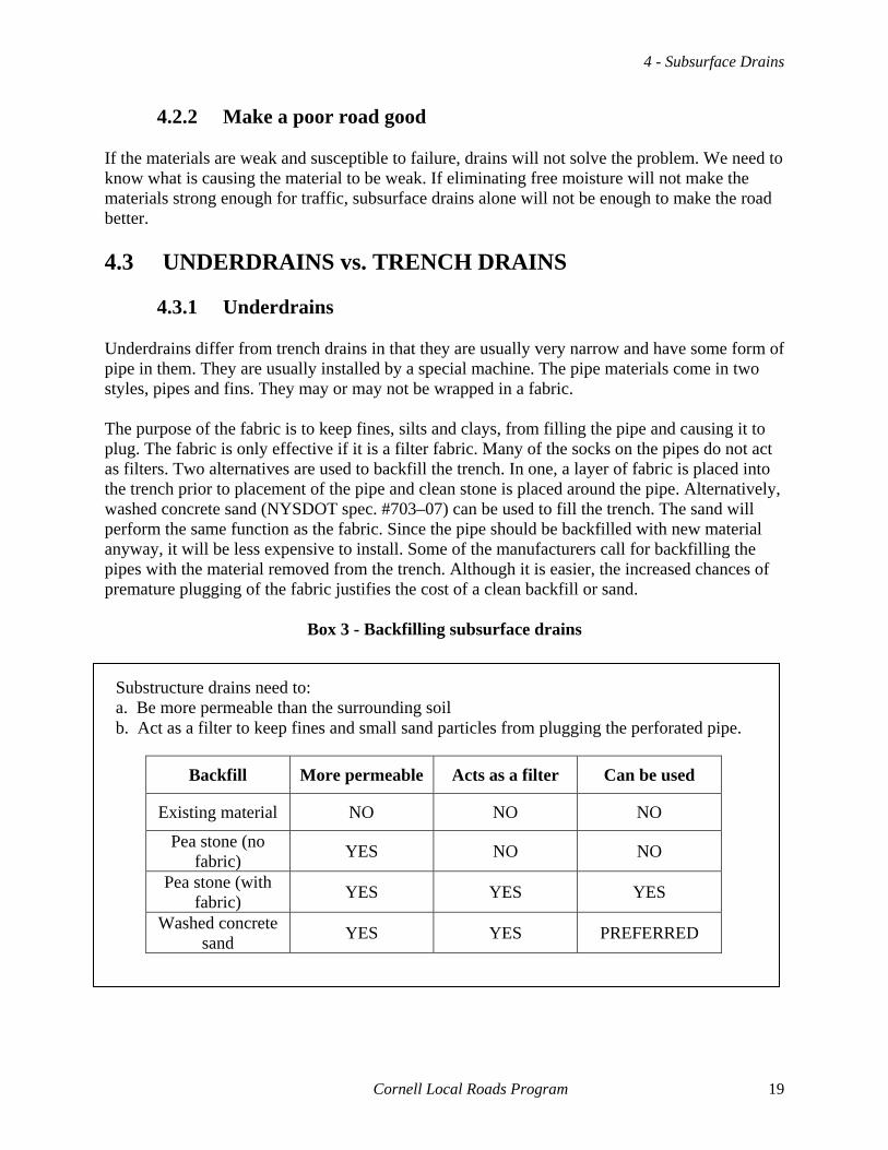
4.3.1 Underdrains Underdrains differ from trench drains in that they are usually very narrow and have some form of pipe in them. They are usually installed by a special machine. The pipe materials come in two styles, pipes and fins. They may or may not be wrapped in a fabric. The purpose of the fabric is to keep fines, silts and clays, from filling the pipe and causing it to plug. The fabric is only effective if it is a filter fabric. Many of the socks on the pipes do not act as filters. Two alternatives are used to backfill the trench. In one, a layer of fabric is placed into the trench prior to placement of the pipe and clean stone is placed around the pipe. Alternatively, washed concrete sand (NYSDOT spec. #703–07) can be used to fill the trench. The sand will perform the same function as the fabric. Since the pipe should be backfilled with new material anyway, it will be less expensive to install. Some of the manufacturers call for backfilling the pipes with the material removed from the trench. Although it is easier, the increased chances of premature plugging of the fabric justifies the cost of a clean backfill or sand.
Box 3 - Backfilling subsurface drains
Backfill More permeable Acts as a filter Can be used
Existing material NO NO NO
Pea stone (no fabric) YES NO NO
Pea stone (with fabric) YES YES YES
Washed concrete sand YES YES PREFERRED
Substructure drains need to: a. Be more permeable than the surrounding soil b. Act as a filter to keep fines and small sand particles from plugging the perforated pipe.
Cornell Local Roads Program 19
Roadway & Roadside Drainage
4" or 6" perforated pipe 12" or 18" fin
Sand backfill Sand backfill
4" or 6" perforated pipe
Pea stone w/fabric wrapped trench
4" or 6" perforated pipe 12" or 18" fin
Sand backfill Sand backfill
4" or 6" perforated pipe
Pea stone w/fabric wrapped trench
4.3.2 Trench Drains
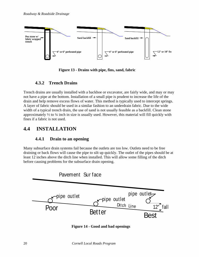
Figure 13 - Drains with pipe, fins, sand, fabric
Trench drains are usually installed with a backhoe or excavator, are fairly wide, and may or may not have a pipe at the bottom. Installation of a small pipe is prudent to increase the life of the drain and help remove excess flows of water. This method is typically used to intercept springs. A layer of fabric should be used in a similar fashion to an underdrain fabric. Due to the wide width of a typical trench drain, the use of sand is not usually feasible as a backfill. Clean stone approximately ½ to ¼ inch in size is usually used. However, this material will fill quickly with fines if a fabric is not used. 4.4 INSTALLATION
4.4.1 Drain to an opening Many subsurface drain systems fail because the outlets are too low. Outlets need to be free draining or back flows will cause the pipe to silt up quickly. The outlet of the pipes should be at least 12 inches above the ditch line when installed. This will allow some filling of the ditch before causing problems for the subsurface drain opening.
12" fal l
Pavement Sur face
Ditch LinePoor Bet ter Best
pipe out letpipe out let pipe out let
Figure 14 - Good and bad openings
20 Cornell Local Roads Program

4 - Subsurface Drains
4.5 MAINTENANCE Subsurface drains are not maintenance free. They need to be cleaned periodically to keep them clean. A sewer cleaner can perform the job very effectively. Only the last 25 feet or so need to be cleaned to re-establish flow. Deeper cleaning may be needed if the pipe has completely plugged. Also, openings need to be cleared of debris and flow at outlets maintained. Animal guards should be installed if rodents start using the pipes as homes and tunnels. When crews are mowing around the drains, care should be taken not to crush or damage the openings.
Cornell Local Roads Program 21

5 - Cross Section Elements
5 - CROSS SECTION ELEMENTS 5.1 PAVEMENT The pavement (subbase, base, and surface) of a roadway should be built and maintained to help eliminate excess water. Water infiltration through the surface is a major concern on local roads, especially gravel surfaces.
5.1.1 Paved vs. gravel A paved road has a higher capital construction cost than a gravel road but may be less expensive to maintain. Asphalt and surface treatments keep dust down and are better suited for high speed and high volume traffic. Gravel roadways may be less expensive, especially at lower traffic volumes. Proper maintenance is critical for both pavement types.
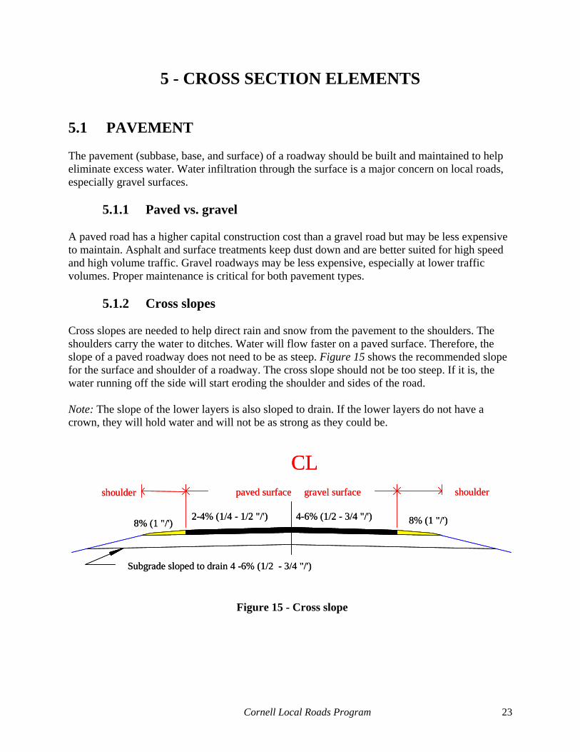
5.1.2 Cross slopes Cross slopes are needed to help direct rain and snow from the pavement to the shoulders. The shoulders carry the water to ditches. Water will flow faster on a paved surface. Therefore, the slope of a paved roadway does not need to be as steep. Figure 15 shows the recommended slope for the surface and shoulder of a roadway. The cross slope should not be too steep. If it is, the water running off the side will start eroding the shoulder and sides of the road. Note: The slope of the lower layers is also sloped to drain. If the lower layers do not have a crown, they will hold water and will not be as strong as they could be.
Subgrade sloped to drain 4 -6% (1/2 - 3/4 "/')
2-4% (1/4 - 1/2 "/') 4-6% (1/2 - 3/4 "/')8% (1 "/') 8% (1 "/')
CLpaved surface gravel surfaceshoulder shoulder
2-4% (1/4 - 1/2 "/') 4-6% (1/2 - 3/4 "/')8% (1 "/') 8% (1 "/')
CLpaved surface gravel surfaceshoulder shoulder
Subgrade sloped to drain 4 -6% (1/2 - 3/4 "/')
Figure 15 - Cross slope
Cornell Local Roads Program 23

Roadway & Roadside Drainage
5.1.3 Sealed surface Sealing the surface with a surface seal or blacktop will lower maintenance costs and reduce the infiltration of water from the top. However, the surface of a gravel road should not be sealed without reducing the fine content of the gravel to the proper gradation.
5.1.4 Repairs
5.1.4.1 Paved roads Crack repairs are needed to keep water out of the pavement. More detail on repairs is available in the SHRP, Asphalt Pavement Repair Manuals of Practice. Three general kinds of repairs are performed as shown in the table below. Surface treatments and overlays may be used to reseal a porous surface.
Table 7 - General repairs
Distress Repair
Moving cracks Crack sealing
Non–moving cracks Crack filling
Alligator cracks Patching
5.1.4.2 Unpaved roads Dragging and reshaping are the most common forms of maintenance on unpaved, gravel roads. This maintenance needs to be done on a routine basis and care should be taken to do it right the first time. Dragging (also known as blading) is done when ruts, depressions, and potholes are infrequent but loose aggregate and minor problems exist. The blade of the grader is set at 90 degrees to the surface and the grader travels very slowly (~ 2 mph) to drag the surface. If the distresses are more than an inch deep, dragging will not solve the problem. It will only fill in the problems and the distress will return very quickly. Regrading is needed to fix severe problems that are more than an inch deep. The grader blade is set at a lower angle, and the operator scarifies below the level of the damage to avoid reoccurrence. Care must be taken not to leave a flat spot at the centerline due to an extra pass. Although easier for the operator, it usually causes potholes to form down the centerline of the road.
24 Cornell Local Roads Program

5 - Cross Section Elements
5.2 SHOULDERS Shoulders help hold snow in the winter, provide lateral support for the pavement, carry water from the pavement to ditches, and give vehicles a place to go if they lose control or need to stop in an emergency. For drainage they need to be slightly steeper than the pavement and should be able to withstand occasional traffic. The material used for the surface should be strong enough to hold occasional traffic. Erosion and washing of shoulders is a major problem and should be addressed by using less erosive materials on the surface. Shoulders by mailboxes may need to be paved or covered with different materials to handle the daily traffic placed upon them.
5.2.1 Maintenance Maintenance of shoulders consists of three basic operations; cutting, filling, and regrading. Cutting is similar to surface dragging in that it is only applicable for small defects. If the grader blade does not go below the defect, the problem will reoccur. The blade needs to be set at a sharp angle, the material brought into the roadway and cleaned up with a loader. Filling ruts at the edge of the shoulder can be done several ways. The material used to fill the rut should be stable and easily compacted. It must be rolled or the rut will reform almost immediately. Where the rut is formed due to traffic such as at a mailbox, the use of asphalt is recommended. Box out of the rut with a backhoe to remove any contaminated material. Regrading is needed when the distresses are too large for cutting and the width of distress is fairly wide. New material should be brought in to replace the material lost in the operation. The new material needs to be stable.
5.2.2 Materials and types Shoulders can be made of several materials. The following table shows some of the possibilities.
Cornell Local Roads Program 25

Roadway & Roadside Drainage
Table 8 - Shoulders (materials and types)
Material Advantages Disadvantages
Earth Cheap Not recommended; erodes easily, and requires lots of maintenance
Grass Pleasing to the eye Not stable under traffic, and easily damaged by snow plows
Surface treated
Provides protection from erosion; is driveable, relatively inexpensive, and can be repaired by hand methods
Once punctured is easily erodible, and joint with pavement difficult to keep sealed
Paved Strong and durable; blocks entry of water under the traveled way Expensive to install
Rock Durable and driveable May erode easily if installed improperly, and does not keep surface water out of pavement
Curb and gutter
Controls water, and helps delineate traffic
Expensive; requires pavement up to gutter or curb, and need drop inlets or catch basins to drain water into a storm water system
5.3 BASE AND SUBGRADE
5.3.1 Daylighting vs. bathtub construction Failure to allow base layers to be drained, sometimes referred to as bathtub construction, will cause holding of excess water and premature failure of the roadway. The best way to stop bathtub construction problems is to daylight the base by carrying the base clear out to a ditch. Another alternative is to install underdrains or trench drains.
26 Cornell Local Roads Program

5 - Cross Section Elements
Poor material
Water trapped in base
Install underdrainsDaylight base
CL
CL
Figure 17 - How to fix bathtub base
Poor material
Water trapped in base
Install underdrainsDaylight base
CL
CL
Figure 16 - Bathtub construction
5.3.2 Subgrade and cross slope
The grading of the subgrade to drain is very important. Failure to provide a positive cross slope in the subgrade will cause water pockets, ice lenses, and other problems to form. The subgrade should be sloped at ¼ inch per foot (¾ inch per foot preferred) and daylighted to a ditch or drainage structure. The subgrade should be rolled prior to placing the base. Otherwise, it will settle during construction and the value of grading the pavement will be lost.
5.3.3 Fabrics (geotextiles) Geotextiles for subsurface construction come in many varieties. They generally are classified as woven or non–woven. The two main purposes for fabrics are separation of different materials, and providing extra strength to existing materials. Some materials used for separation are also used for drainage, but the separation is the primary function. When draining soils or placing gravel over a subgrade or in a trench, a major concern is the mixing or pumping of the materials into each other. A separation fabric, usually non–woven, will keep the material separate by reducing the movement of fines. When used in drainage, the fabric is critical in stopping the migration of fines. The fabric will allow water to flow through, but will trap suspended fines. Use of the wrong fabric can actually create problems. Get help to determine the right fabric to use. DO NOT ASSUME. More details on the installation of geotextiles is available from manufacturers. Also, the manual, Geotextiles Selection and Installation Manual for Rural Unpaved Roads, available from the Cornell Local Roads Program, can be of assistance.
Cornell Local Roads Program 27

Roadway & Roadside Drainage
5.4 DRIVEWAYS Driveways should be graded and sloped to keep water away from the pavement. Failure to do so can result in ice lenses and damage due to excess moisture. Providing positive drainage on driveways can be done with swale construction or intercepting drains.
CL
Figure 18 - Use of swale or intercepting drain to provide positive drainage
Slotted culvert Swale 3-6"
CLSlotted culvert Swale 3-6"
Swale 3–6' Slotted culvert
28 Cornell Local Roads Program
6 - Legal Issues
6 - LEGAL ISSUES When working around roads, we need to be concerned with legal issues. If we do not take care, we can get sued, pay damages, or have work stopped because a few simple procedures are not followed. Keep the elected board informed. Good communication will help solve many problems. 6.1 LAW Each state has legal requirements for working in and around streams. In New York State, regulations and laws are enforced by the New York State Department of Environmental Conservation (DEC). They have police powers and can enforce the laws and regulations with fines, orders to stop work, and penalties. Two general rules of law are in effect with regard to drainage in the United States: Common Law and Civil Law. New York State uses a mixture of the two concepts, identified as reasonable use.
6.1.1 Reasonable use Reasonable use as used in New York State is most closely a modification of English common law. Water is a common enemy. A landowner can improve the land to improve drainage as long as doing so would be a reasonable use for the type of land. But, the landowner cannot improve land so as to cause additional volumes of water to flow onto neighboring land without getting permission and showing justifiable reasons. This includes local governments. However, repairs and replacements of existing drainage structures that are performed as necessary to maintain a road are an acceptable reasonable use of land by a highway department. 6.2 RIGHTS AND RESPONSIBILITIES
6.2.1 Rights Highway agencies have the right to work on roads within the right-of-way (R.O.W.). As long as improvements do not cause damage to properties up or downstream, you can do what you need to do within the R.O.W. You can make improvements, outside the R.O.W., if they are necessary for the safety of the public and would cause economic harm to the municipality if the work is not done. However, landowners may need to be compensated even for work in the R.O.W. if the improvement is not deemed a reasonable use of the land. You will need to get permission for most work prior to leaving the R.O.W. Highway agencies can work outside the right-of-way under limited circumstances. The most common method used to get permission is obtaining an easement. If work must be done off of the right-of-way and the landowner will not sign an easement, eminent domain is a possible recourse. Negotiation and reasonable alternatives are usually better options.
Cornell Local Roads Program 29

Roadway & Roadside Drainage
6.2.2 Responsibilities Highway agencies are the keepers of the land that roads use. This includes the responsibility to treat the land with care and maintain it properly. A stable stream and roadway is as good for the environment as it is easy to maintain. Being a good steward of the land, makes the job of road maintenance easier. Good road building practices and good environmental practices are compatible and complementary. 6.3 RIGHT-OF-WAY/EASEMENTS
6.3.1 Right-of-way (R.O.W.)
6.3.1.1 In the R.O.W. In the R.O.W. you have the right to maintain the road in a manner consistent with the needs of the public. You can replace most pipes, clean ditches, or reconstruct a road with no legal requirements for permission. However, you still need to get permits to work in protected streams. Notifying the public will make your job easier. Locating the edge of the R.O.W. is usually the biggest problem encountered by local agencies. Specific questions about the location of the R.O.W. should be directed to an attorney. Towns generally have a right-of-way by use. Town roads that have been dedicated are a minimum of three rods wide. Counties are covered under Highway Law. If the county does not own the roadway, the right–of–way is usually, but not always, at least three rods wide (49.5 feet). Village and city R.O.W. are different for each street or road as listed in official maps.
30 Cornell Local Roads Program
6 - Legal Issues
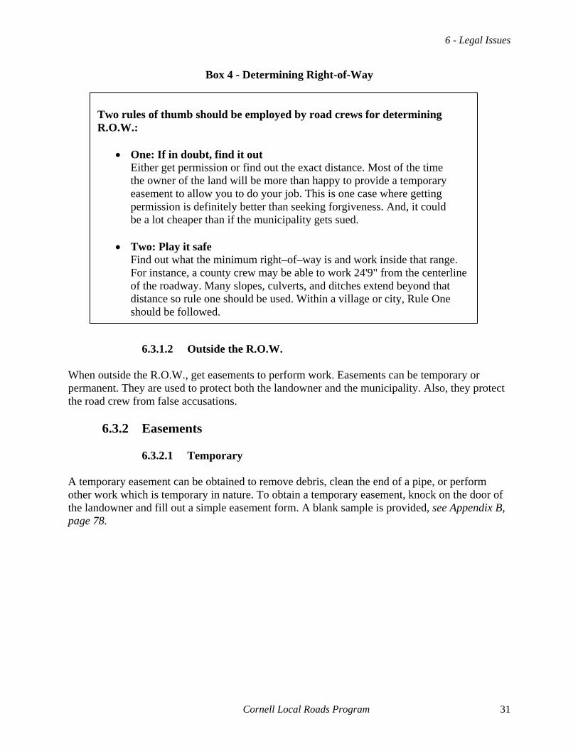
Box 4 - Determining Right-of-Way
Two rules of thumb should be employed by road crews for determining R.O.W.:
• One: If in doubt, find it out Either get permission or find out the exact distance. Most of the time the owner of the land will be more than happy to provide a temporary easement to allow you to do your job. This is one case where getting permission is definitely better than seeking forgiveness. And, it could be a lot cheaper than if the municipality gets sued.
• Two: Play it safe
Find out what the minimum right–of–way is and work inside that range. For instance, a county crew may be able to work 24'9" from the centerline of the roadway. Many slopes, culverts, and ditches extend beyond that distance so rule one should be used. Within a village or city, Rule One should be followed.
6.3.1.2 Outside the R.O.W.
When outside the R.O.W., get easements to perform work. Easements can be temporary or permanent. They are used to protect both the landowner and the municipality. Also, they protect the road crew from false accusations.
6.3.2 Easements
6.3.2.1 Temporary A temporary easement can be obtained to remove debris, clean the end of a pipe, or perform other work which is temporary in nature. To obtain a temporary easement, knock on the door of the landowner and fill out a simple easement form. A blank sample is provided, see Appendix B, page 78.
Cornell Local Roads Program 31

Roadway & Roadside Drainage
Figure 19 - Temporary easement (blank form in Appendix B, page 78)
32 Cornell Local Roads Program

6 - Legal Issues
6.3.2.2 Permanent A permanent easement is needed to extend a pipe, cut a slope, or perform other work of a permanent nature. Consult your municipal attorney for advice. 6.4 PERMITS AND PROCEDURES Obtain permits for some drainage work, and follow certain procedures before starting any work.
6.4.1 One-Call Organizations A one-call organization must be called for any work involving digging into the ground. A free phone call three working days prior to starting work is required. They will contact necessary utilities. Within two full working days after the call, marks are made around the work site showing the location of any utilities. It is a lot better to wait than pay to replace a fiber–optic cable or cause the death of an employee due to an exploding gas pipe. Dig Safely, NY is the one–call organization in New York State, (outside of New York City, and Long Island). In New York City and Long Island, you should call 1 (800) 272-4480.
Figure 20 - Dig Safely telephone number in New York State
Figure 21 - One-call telephone number in New York City and Long Island
6.4.2 PERMITS
6.4.2.1 Department of Environmental Conservation (NYS DEC) Army Corps of Engineers (ACOE)
6.4.2.1.1 Protection of Waters & Freshwater Wetlands
Programs When working in a stream, along a lake or other shoreline, or near a wetland, a permit to do the work should be obtained from the NYS DEC /ACOE before starting work. Your local NYS DEC office has the forms. They, along with the local Soil and Water Conservation District (SWCD), can offer advice to make the work more successful and less expensive.
Cornell Local Roads Program 33

Roadway & Roadside Drainage
6.4.2.1.2 SPDES (State Pollutant Discharge Elimination System) Permit
If working on a new development or reconstruction of a road that exposes more than one acre of land to erosion, a SPDES permit needs to be obtained from the NYS DEC. For most reconstruction work, the permit will be a general blanket permit that does not require much paperwork. Contact the NYS DEC for more information. While most routine maintenance activities do not require a permit, care should be taken to reduce erosion. Municipalities may still be liable for any damage due to poor maintenance or construction practice. As a general rule of thumb, any capital construction more than ¼ mile in length will need the SPDES permit. Good construction practices should always be used for any repair activity.
6.4.2.2 Other permits The permits listed above are a few of the more common permits used in New York State. Many other permits may be needed to do drainage work. The DEC has other permits such as Coastal Erosion Control and Tidal Wetlands. In addition, agencies like the Adirondack Park Agency and local jurisdictions may have their own permits and regulations. You should check with them prior to starting work. This is one time when getting forgiveness does not work.
6.4.2.3 Cleaning streams Cleaning a stream by running a bulldozer up the stream and straightening it out does not work. This has to be repeated on a regular basis. Streams need a constant slope for a given flow. If the slope is too steep, there will be siltation or scour until the stream is at the same slope it had before cleaning was done. Straightening out a stream changes the slope. Commonly, the lower end of the cleaned section, usually by the road, will silt up. The cleaning will need to be done again. Contact the NYS DEC for advice on how to perform this work and still meet requirements and regulations. In addition, straightening a stream is not stable. The banks and bed of the stream have certain characteristic shapes and slopes. You cannot fight nature, you need to work with it. A general rule of thumb is, a stable stream bed maintains itself.
34 Cornell Local Roads Program

7 - Culverts
7 - CULVERTS A culvert helps move water under a road or driveway to a stream, lake, or detention basin. While culverts can, and have been, defined in many ways (such as any span under 20 feet), for drainage, a culvert is usually prefabricated and comes in standard sizes. In addition, a culvert is allowed to have the ends completely submerged. The first item we need to understand is the amount of flow a culvert will need to carry. Then we can look at the materials, installation, inspection, and maintenance. 7.1 HYDROLOGY AND HYDRAULICS In the simplest terms, hydrology is concerned with measuring the amount of runoff and precipitation that flows to a particular spot such as a culvert inlet. Hydraulics is the determination of the amount of flow capacity in a given culvert, ditch, or other drainage structure. Detailed engineering studies can calculate these two quantities. However, most culverts and driveways do not need detailed studies. A rule of thumb can be used to do most culvert sizing and alignments. For larger structures and culverts, detailed studies may be needed. Resources available to help design culverts and determine flows are: the Cornell Local Roads Program, Soil and Water Conservation Districts, county highway departments, consulting engineers, and other municipal engineering personnel.
7.1.1 Runoff The first step in determining the size of a culvert (or other drainage structure, including ditches) is calculating the runoff or flow coming to a culvert. Several methods exist for determining the amount of flow. TR–55; the Soil Conservation Service’s Graphical method; the Bureau of Public Roads; the Rational method; and other methods are used to determine the amount of runoff. The Rational method, used for small watersheds, is useful to explain the concepts of runoff. Runoff at a specific site is controlled by many factors including the intensity of precipitation, the area of the watershed, and the proportion of rainfall which gets to the culvert.
Cornell Local Roads Program 35
Roadway & Roadside Drainage
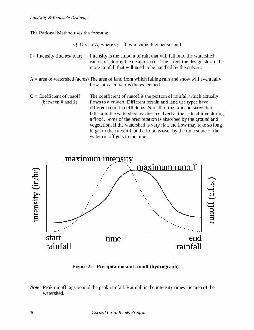
The Rational Method uses the formula:
Q=C x I x A, where Q = flow in cubic feet per second I = Intensity (inches/hour) Intensity is the amount of rain that will fall onto the watershed each hour during the design storm. The larger the design storm, the more rainfall that will need to be handled by the culvert. A = area of watershed (acres) The area of land from which falling rain and snow will eventually flow into a culvert is the watershed. C = Coefficient of runoff The coefficient of runoff is the portion of rainfall which actually
(between 0 and 1) flows to a culvert. Different terrain and land use types have different runoff coefficients. Not all of the rain and snow that falls onto the watershed reaches a culvert at the critical time during a flood. Some of the precipitation is absorbed by the ground and vegetation. If the watershed is very flat, the flow may take so long to get to the culvert that the flood is over by the time some of the water runoff gets to the pipe.
time
inte
nsity
(in/
hr)
runo
ff (c
.f.s.)
maximum intensitymaximum runoff
startrainfall
endrainfall
time
inte
nsity
(in/
hr)
runo
ff (c
.f.s.)
maximum intensitymaximum runoff
startrainfall
endrainfall
Figure 22 - Precipitation and runoff (hydrograph)
Note: Peak runoff lags behind the peak rainfall. Rainfall is the intensity times the area of the
watershed.
36 Cornell Local Roads Program

7 - Culverts
Figure 23 - Area of watershed (USGS map)
Note: The ridges and peaks define the perimeter of the watershed.
Table 9 - Coefficient of runoff (table of values)
C Land type
0.1 – 0.4 Forested land
0.3 – 0.4 Suburban residential areas
0.3 – 0.5 Single–family residences
0.7 – 0.9 Downtown business districts
0.1 – 0.2 Parks and cemeteries
0.2 – 0.4 Pastures
0.2 – 0.5 Cultivated land
0.8 – 0.9 Paved development
Cornell Local Roads Program 37

Roadway & Roadside Drainage
7.1.2 Land use Land use can affect the amount of runoff. In fact, it is the reason many culverts, which had previously been fine and handled heavy rains, have flooded and washed out. For example, if a forested area is cleared and a parking lot and building are put in on a 10–acre site and no detention basins or other mitigation is done, the flow could increase by up to 400 percent. Use of detention basins and other mitigation may need to be done if the land use changes drastically.
7.1.3 Design storm Engineers use the concept of a design storm to determine the amount of flow a pipe needs to handle. The design storm is the average time between storms. A storm which has a 1/25 chance of occurring in a given year is called a 25–year storm. Since 1/25 is 4 percent, the storm is also known as a 4 percent storm. A 50–year storm would be one with a 1/50 (2 percent) chance of occurring in a given year. Since 4 percent is twice 2 percent, a 25–year storm is twice as likely to occur in a given year as a 50–year storm. If a 50–year storm occurs in a given year, it does not mean another 50–year storm will not occur for 50 years. Each year the chances of a given storm are the same.
Box 5 - 50-year storm
Figure 24 - Pick a card
Take a card from a deck of 50 cards (a standard deck without the 2 of clubs and 2 of spades). The chance of picking the Ace of spades is 1/50. If you put the card back in the deck and reshuffle, what are the chances of picking the Ace of spades? Still 1/50, just like the 50-year storm in a given year.
The greater the design storm value (in years) the less likelihood of a flood causing a failure during the life of the culvert. What storm should be used for design? The initial cost of placing a larger pipe needs to be weighed against the risk of failure. Placing a pipe which is too small means the chances of washout or failure may be too great. Placing too large of a pipe may be uneconomical and dangerous if, as an example, the depth of a ditch needed for the culvert is so deep it will swallow up cars if they drive into it. During heavy rains some flooding will occur. The objective of a highway department is to build culverts which can survive a storm and be in service after the rain has lessened. To this end, we design for different design storms for different situations. Table 10 shows the design year for different roads. In all cases, the minimum pipe size should be 12 inches for driveways and 18 inches for culverts.
38 Cornell Local Roads Program

7 - Culverts
Table 10 - Design year for various road types and drainage items
Road type Culvert Driveway Ditches Town roads/Village streets with low traffic 10 5 5 Town roads/Village streets with high traffic 25 10 10 County roads with low traffic 25 10 10 County roads with high traffic 50 25 25 Arterials (State and very important roads) 100 50 50
All of the above aside, there are three things to remember:
• Most pipes can be designed using general rules of thumb (see Section 7.5, CHOOSING PIPE SIZE)
• A 100–year storm volume is not two times the 50–year storm. Listed below is an example from two moderately–sized watersheds. Get help to calculate the amount of runoff.
• Changes in land use and stream bed conditions affect the capability of a culvert to
handle high flows. Cleaning a stream or new developments may cause flooding at pipes which have been adequate for many years.
Table 11 - Runoff from two watersheds using different analyses (cubic feet per second)
Watershed 1 2 Drainage area 240 ac 240 ac 240 ac 161 ac 161 ac
Analysis BPR TR–55 Rational TR–55 Rational Design storm (year)
10 103 101 115 101 78 25 140 139 135 136 92 50 155 165 162 160 109 100 165 179 173 172 116
Notes:
• The three methods are very similar for the first watershed. • Note the similarity in runoff using the TR–55 method between the two watersheds. The
faster runoff in Watershed 2 is due to a steeper watershed. • The difference between the values on Watershed 2 is due to ponding in the watershed.
The TR–55 method only allows a maximum of 5 percent ponding and swamps in a given watershed.
Cornell Local Roads Program 39

Roadway & Roadside Drainage
7.2 MATERIALS, SHAPES, and SIZES Culvert pipes come in many materials, shapes, and sizes. Each material has its own characteristics and advantages. The four most common materials are corrugated metal pipe (CMP), plastic, concrete, and smooth steel. The pipes are generally thought of in two broad categories which correspond to the way they carry loads, rigid and flexible. Flexible pipe (CMP and plastic) gains strength by transferring some of the load into the surrounding soil. Imagine what would happen if you drove a fully loaded truck over a flexible pipe. It would crush. It gains strength from the surrounding soil when it flexes. Flexible pipes must be backfilled properly and have a minimum amount of cover or the loads do not build up in the soil and the pipe will fail. They are generally less expensive to place than rigid pipes but do not last as long. Coatings may increase their lifespan. Failure to bed the pipe carefully will shorten the life of the pipe and may cause premature failure. Rigid pipes (concrete, heavy steel, and masonry) are strong enough by themselves to carry all loads. The transferring of loads is of secondary benefit. They generally last longer than flexible pipes but are much more expensive to place. Cranes and larger equipment are usually needed to set them.
7.2.1 Corrugated metal pipe Sometimes referred to as CMP (corrugated metal pipe), metal pipe is the most common type of material used in culverts. The versatility of the pipe and the wide range of shapes and sizes available make it a very useful product. The base metal can be steel or aluminum. Coatings can be added to increase lifespan, reduce corrosion, and improve hydraulics (flow capacity). Steel is the most common metal used, but is usually galvanized for corrosion protection. The steel may be mixed or coated with an aluminum alloy which is more durable than galvanizing alone and does not increase the price significantly. Or, the pipe can be made of all aluminum. Care should be taken when installing an aluminum pipe, because it is easily damaged. Asphalt and concrete coatings are sometimes added for durability, improved flow characteristics, and resistance to wear from stream bed materials.
40 Cornell Local Roads Program

7 - Culverts
Metal pipes are manufactured in a variety of shapes as shown. Listed beside each are some of the reasons for using the different shapes.
ROUND Easy and inexpensive to manufacture. Has a high flow capacity. Sizes up to 12 inches in diameter. PIPE-ARCH Good hydraulic characteristics when low cover is available and easily manufactured. Up to 10–inch equivalent. BOX Very good hydraulically but relatively expensive and care must be taken to backfill evenly and completely. ARCH Can reach spans of 40 feet or more. Must have a very good foundation and be well constructed. May be very economical when compared to a bridge.
Figure 2 - Pipe shapes (metal)
7.2.2 Plastic Plastic pipe, usually made of high density polyethylene (HDPE), is the fastest growing pipe in terms of use. It is easy to construct due to its light weight and is easy to maneuver and cut. It can be used in a variety of applications including lining existing pipes. It can be lined with a smooth section of plastic to increase flow capacity and improve strength. Plastic pipe is flammable and can be burned. The pipes are limited in size to about six feet and are uneconomical for many applications if more than four feet in diameter. New processes may provide more pipe types and sizes in the future.
Plastic pipes only come in a round shape currently, up to 6 feet in diameter for smooth pipes, and 2 feet for corrugated pipes.
Figure 26 - Pipe shapes (plastic)
Cornell Local Roads Program 41
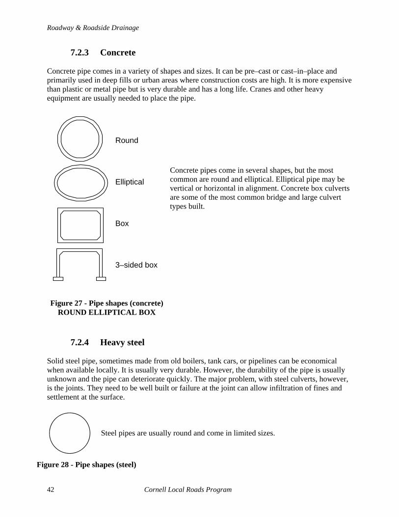
Roadway & Roadside Drainage
7.2.3 Concrete Concrete pipe comes in a variety of shapes and sizes. It can be pre–cast or cast–in–place and primarily used in deep fills or urban areas where construction costs are high. It is more expensive than plastic or metal pipe but is very durable and has a long life. Cranes and other heavy equipment are usually needed to place the pipe.
Concrete pipes come in several shapes, but the most common are round and elliptical. Elliptical pipe may be vertical or horizontal in alignment. Concrete box culverts are some of the most common bridge and large culvert types built.
7.2.4 Heavy steel
Solid steel pipe, sometimes made from old boilers, tank cars, or pipelines can be economical when available locally. It is usually very durable. However, the durability of the pipe is usually unknown and the pipe can deteriorate quickly. The major problem, with steel culverts, however, is the joints. They need to be well built or failure at the joint can allow infiltration of fines and settlement at the surface.
Steel pipes are usually round and come in limited sizes.
Box
Elliptical
Round
Figure 27 - Pipe shapes (concrete) ROUND ELLIPTICAL BOX
3–sided box
Figure 28 - Pipe shapes (steel)
42 Cornell Local Roads Program

7 - Culverts
settlementhole settlementsettlementholehole
Effect on pavement Effect on unpaved areas
Figure 29 - Settlement due to poor joints
7.2.5 Durability
Concrete pipe is the most durable with an expected life of 75 to 100 years. It is expensive to install, but in deep fills and urban areas (villages and cities) it is usually justified by comparing the cost of replacement to the amount of time between replacement. Solid steel is usually the next most durable. However, if you buy a used pipe, the lifespan may be very short. Plastic and corrugated metal are about the same in durability. Steel pipe is better able to handle bed loads and debris but is very susceptible to corrosion due to low pH water (acidic) which is found in the Southern Tier and parts of the Adirondacks. Other areas may have high alkalinity in the soil. In those areas, plastic pipe or lining of pipes may be necessary to keep pipe from corroding early. Plastic and corrugated metal pipes have a 25 to 50 year life if designed and built properly. Also, bed load can cause premature failure. Lining of existing pipes, or adding liners during construction may be useful. 7.3 WHAT IS THE BEST TYPE OF PIPE MATERIAL TO USE?
THERE IS NO ONE BEST MATERIAL TYPE TO USE!
Cost, ease of installation, durability, capacity, and availability all must be factored into any decision about the type of pipe material to use. Capacity is usually the least critical in determining the choice of material for round pipe when there is plenty of cover. There are times when a pipe material should not be used.
Cornell Local Roads Program 43

Roadway & Roadside Drainage
7.4 SIZE AND CAPACITY How large of a pipe is needed? Several factors need to be considered. First let’s discuss the factors. Then we will bring all of the results together below. The flow capacity of a pipe is determined by several factors including the:
• Area and shape of the opening of the pipe • Allowable head or amount of backwater • Kind of inlet • Culvert length and slope • Material used (roughness of the pipe) • Other factors including constrictions of flow due to debris, tailwater, or channel
alignment
Allowable head
Length
Tailwater depth
Shape and areaof barrel
Slope RoughnessInlet type
Allowable head
Length
Tailwater depth
Shape and areaof barrel
Slope RoughnessInlet type
Figure 30 - Factors determining flow capacity of a pipe
7.4.1 Area and shape of opening By far the most critical factor for determining capacity is the area of the opening of the pipe. The amount of flow that can go through a culvert is directly proportional to the area of the opening. Doubling the area doubles the capacity of the pipe. An 18–inch diameter pipe has more than twice the capacity of a 12–inch diameter pipe because the area is more than twice as large. (18–inch diameter pipe area = 254 in2 vs. 12–inch diameter pipe area = 113 in2).
Box 6 - Diameter versus area
Figure 30 Factors determining flow capacity of a pipe
If a new driveway needs a 24-inch pipe and the homeowner says he has two 12-inch pipes, is the area of the two 12-inch pipes equivalent to the 24-inch pipe? NO! Area is a function of the square of the diameter. A 24-inch pipe has 4 times the capacity of a 12-inch pipe. The homeowner would need four 12-inch pipes to replace a single 24-inch pipe.
Figure 31 - 12" vs. 24" pipe
2 2 452 in2 452 in2
(117 in2 each)
44 Cornell Local Roads Program
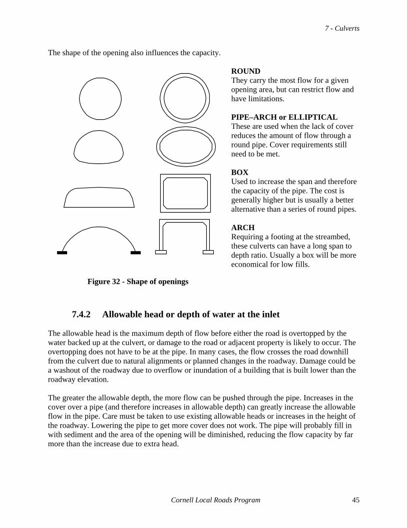
7 - Culverts
The shape of the opening also influences the capacity. ROUND They carry the most flow for a given opening area, but can restrict flow and have limitations. PIPE–ARCH or ELLIPTICAL These are used when the lack of cover reduces the amount of flow through a round pipe. Cover requirements still need to be met. BOX Used to increase the span and therefore the capacity of the pipe. The cost is generally higher but is usually a better alternative than a series of round pipes. ARCH Requiring a footing at the streambed, these culverts can have a long span to depth ratio. Usually a box will be more economical for low fills.
Figure 32 - Shape of openings
7.4.2 Allowable head or depth of water at the inlet
The allowable head is the maximum depth of flow before either the road is overtopped by the water backed up at the culvert, or damage to the road or adjacent property is likely to occur. The overtopping does not have to be at the pipe. In many cases, the flow crosses the road downhill from the culvert due to natural alignments or planned changes in the roadway. Damage could be a washout of the roadway due to overflow or inundation of a building that is built lower than the roadway elevation. The greater the allowable depth, the more flow can be pushed through the pipe. Increases in the cover over a pipe (and therefore increases in allowable depth) can greatly increase the allowable flow in the pipe. Care must be taken to use existing allowable heads or increases in the height of the roadway. Lowering the pipe to get more cover does not work. The pipe will probably fill in with sediment and the area of the opening will be diminished, reducing the flow capacity by far more than the increase due to extra head.
Cornell Local Roads Program 45

Roadway & Roadside Drainage
Roadway
Projecting end
Roadway
Mitered end
Roadway
Headwall end
Roadway
Projecting end
Roadway
Mitered end
Roadway
Headwall end
Roadway
Projecting end
Roadway
Mitered end
Roadway
Headwall end
Figure 33 - Inlet (outlet) designs (projecting, mitered, and headwall)
7.4.3 Kind of inlet
The most common inlet (and outlet) type is the projecting pipe. Small increases in the capacity can be gained by using the mitered or headwall inlet. Also, use of special ends on both the upstream and downstream side can reduce scour, improve appearance, and make maintenance easier. The extra capacity in a culvert due to use of inlets is anywhere from no increase to 10 percent increase in the flow capacity. Most commonly, inlets are placed to improve characteristics other than flow. Mitering the pipe to fit the slope makes the slope safer for errant vehicles and is easier to maintain. However, the ends are susceptible to failure if the ends are not anchored properly. A set of #8 rebars placed on a one–foot grid over the opening allows the highway department to eliminate the use of guiderail. The bars help keep debris out of the pipe. Care must be taken to leave an opening below the grate to allow the majority of the flow through the pipe or plugging can occur and damage the pipe. Special ends can be purchased to attach to the ends of most round pipes. The price can be very high for larger pipes, but the ends protect against scour, have good appearances, and can be protected by a rebar grate in the same way a metered end is protected. In addition, if there is a need to extend the pipe in the future, the end can be removed, a new section of pipe added to the first section, and the end replaced.
46 Cornell Local Roads Program
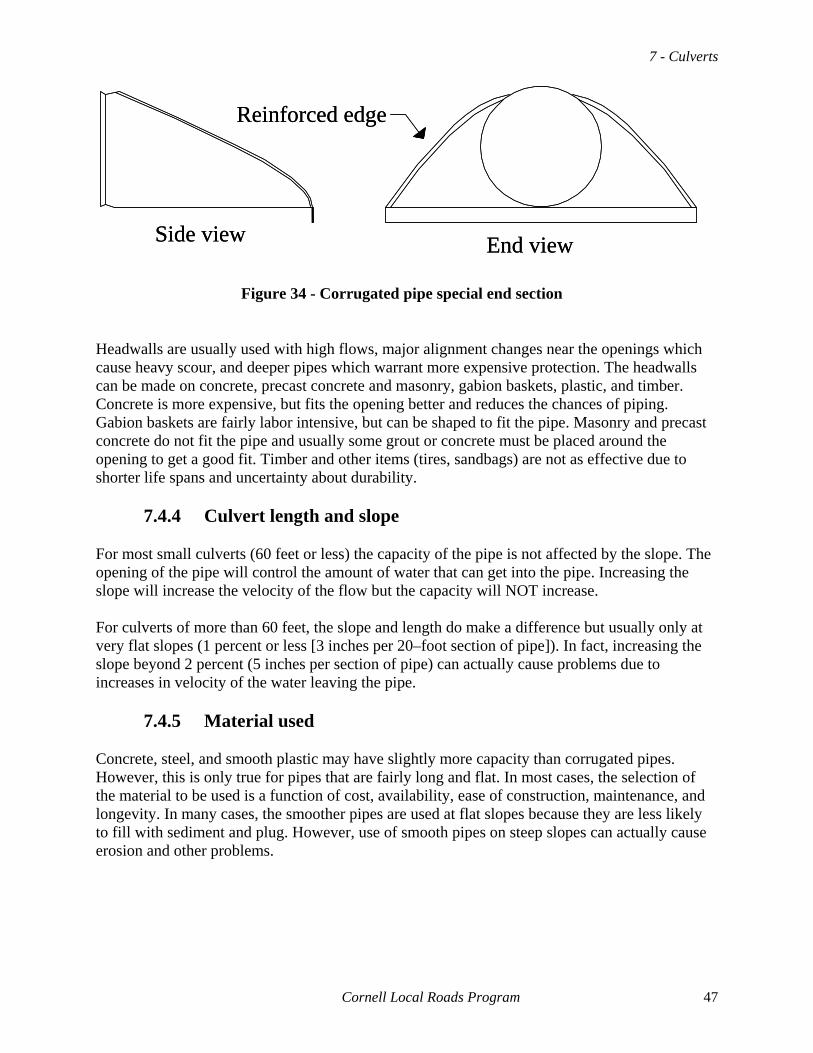
7 - Culverts
Reinforced edge
Side view End view
Reinforced edge
Side view End view
Figure 34 - Corrugated pipe special end section
Headwalls are usually used with high flows, major alignment changes near the openings which cause heavy scour, and deeper pipes which warrant more expensive protection. The headwalls can be made on concrete, precast concrete and masonry, gabion baskets, plastic, and timber. Concrete is more expensive, but fits the opening better and reduces the chances of piping. Gabion baskets are fairly labor intensive, but can be shaped to fit the pipe. Masonry and precast concrete do not fit the pipe and usually some grout or concrete must be placed around the opening to get a good fit. Timber and other items (tires, sandbags) are not as effective due to shorter life spans and uncertainty about durability.
7.4.4 Culvert length and slope For most small culverts (60 feet or less) the capacity of the pipe is not affected by the slope. The opening of the pipe will control the amount of water that can get into the pipe. Increasing the slope will increase the velocity of the flow but the capacity will NOT increase. For culverts of more than 60 feet, the slope and length do make a difference but usually only at very flat slopes (1 percent or less [3 inches per 20–foot section of pipe]). In fact, increasing the slope beyond 2 percent (5 inches per section of pipe) can actually cause problems due to increases in velocity of the water leaving the pipe.
7.4.5 Material used Concrete, steel, and smooth plastic may have slightly more capacity than corrugated pipes. However, this is only true for pipes that are fairly long and flat. In most cases, the selection of the material to be used is a function of cost, availability, ease of construction, maintenance, and longevity. In many cases, the smoother pipes are used at flat slopes because they are less likely to fill with sediment and plug. However, use of smooth pipes on steep slopes can actually cause erosion and other problems.
Cornell Local Roads Program 47

Roadway & Roadside Drainage
7.4.6 Miscellaneous considerations Several other factors can influence the capacity of a culvert, but do not generally affect most typical installations.
7.4.6.1 Tailwater The tailwater is the depth of water ponded or flowing at the downstream side of a pipe. It can restrict the flow through the pipe and reduce capacity. If tailwater is a concern, GET HELP!
7.4.6.2 Alignment Alignment of the pipe can be important for two reasons, capacity and scour. Trying to turn water at the end of a culvert creates eddies in the flow and slows the velocity of the water. This can reduce the amount of water getting to the pipe. Therefore, the capacity is reduced. Also, siltation can occur due to the changes in the velocity. Use natural alignments where possible.
7.4.6.3 Debris Debris plugging or covering a pipe can reduce capacity. Maintenance and debris catchers should be used if this is a problem.
7.4.6.4 Multiple pipes Multiple pipes are used when a single pipe will not fit the site due to lack of cover or other problems. Debris catching the ends between the pipes is a major problem. Multiple pipes need to be placed such that low flows use one pipe more than another and debris is handled. Having one pipe slightly lower is a common method used to direct low flows.
Distance...minimum 12"...1/2 diameter...maximum 36"
...minimum 12"
...1/3 span
...maximum 36"
Diameter Span
Distance...minimum 12"...1/2 diameter...maximum 36"
...minimum 12"
...1/3 span
...maximum 36"
Diameter Span
Figure 3 - Spacing between pipes
48 Cornell Local Roads Program
7 - Culverts
7.4.6.5 Velocity and Erosion We need to be concerned at all times about erosion and scour. Culverts usually restrict the flow of a stream. In addition, pipes are usually smoother than the ground, and the velocity of water flowing out of a pipe is usually greater than that flowing into a pipe. If a pipe is placed too steep, the water flowing out the pipe will cause erosion and can cause the pipe to washout from the downstream end.
7.4.6.6 Inlets (scour) At the entrance to a culvert, water will flow and swirl as it tries to enter the pipe. This can cause erosion called scour. Scouring can wash out the entire pipe. Headwalls, end sections, and other treatments are used to mitigate or eliminate the problem. With slow velocities and low flows this is not critical, but care must be taken to avoid this problem. Also, the inlet can be plugged by sedimentation of material at the inlet due to a sudden change in velocity of the water. Especially after storms, culverts need to be inspected to see if sedimentation or debris has plugged or partially covered the opening. Debris should be cleaned as soon as possible to keep the culvert from failing. Beavers using culverts as dam sites are fairly common. Several methods are used to fool the beaver. The methods must have the same flow as the existing culvert, be sturdy, and should be relatively inexpensive. The CLRP or NYS DEC can provide information on beaver control options. Request Managing Nuisance Beavers Along Roadsides: A Guide for Highway Departments from the Cornell Local Roads Program.
7.4.6.7 Outlets (scour) At the outlet of the pipe, the high velocity of the water flowing out of the pipe, as well as the bed material which flows through the pipe, can cause erosion and scour. Energy dissipaters such as rip–rap, gabion check dams, and aprons are all commonly used to help the flow of water away from a pipe without scour. 7.5 CHOOSING PIPE SIZE All of the above aside, there are general rules of thumb that can be used for most pipes.
• New pipes For new pipes, small drainage areas can be designed using simple methods. If the watershed area is less than 20 acres, the minimum pipe size should be 8 inches plus the number of acres. As an example, if a watershed was 14 acres, the pipe should be at least 22 (8 + 14) inches in diameter. You would round up to the next larger size and use a 24-inch diameter pipe. No pipe less than 18 inches should be used for a culvert. No pipe less than 12 inches should be used for a driveway.
Cornell Local Roads Program 49
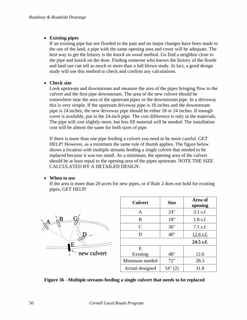
Roadway & Roadside Drainage
• Existing pipes
If an existing pipe has not flooded in the past and no major changes have been made to the use of the land, a pipe with the same opening area and cover will be adequate. The best way to get the history is the knock on wood method. Go find a neighbor close to the pipe and knock on the door. Finding someone who knows the history of the floods and land use can tell as much or more than a full blown study. In fact, a good design study will use this method to check and confirm any calculations.
• Check size Look upstream and downstream and measure the area of the pipes bringing flow to the culvert and the first pipe downstream. The area of the new culvert should be somewhere near the area of the upstream pipes or the downstream pipe. In a driveway this is very simple. If the upstream driveway pipe is 18 inches and the downstream pipe is 24 inches, the new driveway pipe should be either 18 or 24 inches. If enough cover is available, put in the 24-inch pipe. The cost difference is only in the materials. The pipe will cost slightly more, but less fill material will be needed. The installation cost will be almost the same for both sizes of pipe. If there is more than one pipe feeding a culvert you need to be more careful. GET HELP! However, as a minimum the same rule of thumb applies. The figure below shows a location with multiple streams feeding a single culvert that needed to be replaced because it was too small. As a minimum, the opening area of the culvert should be at least equal to the opening area of the pipes upstream. NOTE THE SIZE CALCULATED BY A DETAILED DESIGN.
• When to use If the area is more than 20 acres for new pipes, or if Rule 2 does not hold for existing pipes, GET HELP!
Culvert Size Area of
opening A 24" 3.1 s.f. B 18" 1.8 s.f. C 36" 7.1 s.f. D 48" 12.6 s.f.
24.5 s.f. E
Existing 48" 12.6 Minimum needed 72" 28.3 Actual designed 54" (2) 31.8
A B C
D
Enew culvert
A B C
D
Enew culvert
Figure 36 - Multiple streams feeding a single culvert that needs to be replaced
50 Cornell Local Roads Program

7 - Culverts
7.6 PLANNING A CULVERT REPLACEMENT Planning the replacement of a culvert is a fairly straightforward project. Several factors must be considered. If any part of the replacement is of concern, GET HELP.
7.6.1 Alignment First, choose an alignment. Use of natural alignment reduces scour, is generally no more expensive to install and is much less expensive to maintain. The extra length of pipe needed for a natural alignment is offset in cost by the need to provide extra scour protection and the chances of long–term problems. Exceptions to a natural alignment are:
• Existing pipe system is working fine • There is a need to have a closed system in a developed area or village • The cost of a natural alignment is prohibitive • Or, other factors make the natural alignment less cost effective
Natural Alignment
NaturalAlignment
Good alignmentPoor alignment
Natural Alignment
NaturalAlignment
Good alignmentPoor alignment
Figure 37 - Natural vs. artificial alignments
We normally express the alignment in degrees skew. For determining the amount of pipe to be used we need to know the skew ratio. The skew ratio is the length of a pipe along the new alignment versus a perpendicular alignment expressed in feet offset per feet of length perpendicular to the road. The easiest way to measure this distance is to measure a 10–foot width on one lane, the length of the pipe along the alignment in the 10–foot distance (“C” in Figure 38), and divide the result by 10.
Cornell Local Roads Program 51
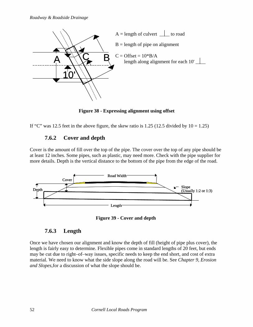
Roadway & Roadside Drainage
A BC
10'
If “C” was 12.5 feet in the above figure, the skew ratio is 1.25 (12.5 divided by 10 = 1.25)
7.6.2 Cover and depth Cover is the amount of fill over the top of the pipe. The cover over the top of any pipe should be at least 12 inches. Some pipes, such as plastic, may need more. Check with the pipe supplier for more details. Depth is the vertical distance to the bottom of the pipe from the edge of the road.
7.6.3 Length
Once we have chosen our alignment and know the depth of fill (height of pipe plus cover), the length is fairly easy to determine. Flexible pipes come in standard lengths of 20 feet, but ends may be cut due to right–of–way issues, specific needs to keep the end short, and cost of extra material. We need to know what the side slope along the road will be. See Chapter 9, Erosion and Slopes,for a discussion of what the slope should be.
Figure 38 - Expressing alignment using offset
Figure 39 - Cover and depth
A = length of culvert to rB = length of pipe on alignm
oadent
C =length along alignment for each 10'
Offset = 10*B/AA B
A = length of culvert to rB = length of pipe on alignm
oadent
C =length along alignment for each 10'
Offset = 10*B/AC
10'
A = length of culvert ____ to road B = length of pipe on alignment C = Offset = 10*B/A
length along alignment for each 10' ____
Depth
Length
Slope(Usually 1:2 or 1:3)
CoverRoad Width
Depth
Length
Slope(Usually 1:2 or 1:3)
CoverRoad Width
52 Cornell Local Roads Program
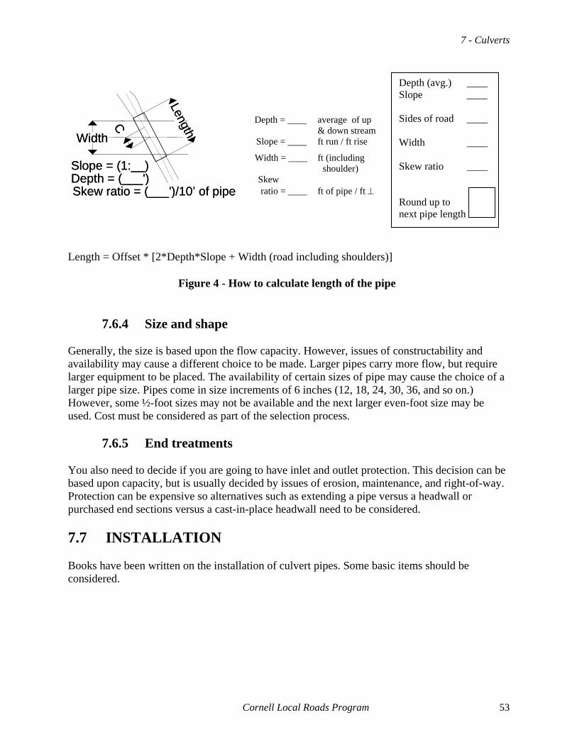
7 - Culverts
Depth (avg.) ____ Slope ____ Sides of road ____ Width ____ Skew ratio ____ Round up to next pipe length
LengthC
Width
Slope = (1:__)Depth = (___')Skew ratio = (___')/10’ of pipe
LengthC
Width
Slope = (1:__)Depth = (___')Skew ratio = (___')/10’ of pipe
Depth = ____ average of up
& down stream Slope = ____ ft run / ft rise
Width = ____ ft (including shoulder)
Skew ratio = ____ ft of pipe / ft ⊥
Length = Offset * [2*Depth*Slope + Width (road including shoulders)]
Figure 4 - How to calculate length of the pipe
7.6.4 Size and shape Generally, the size is based upon the flow capacity. However, issues of constructability and availability may cause a different choice to be made. Larger pipes carry more flow, but require larger equipment to be placed. The availability of certain sizes of pipe may cause the choice of a larger pipe size. Pipes come in size increments of 6 inches (12, 18, 24, 30, 36, and so on.) However, some ½-foot sizes may not be available and the next larger even-foot size may be used. Cost must be considered as part of the selection process.
7.6.5 End treatments You also need to decide if you are going to have inlet and outlet protection. This decision can be based upon capacity, but is usually decided by issues of erosion, maintenance, and right-of-way. Protection can be expensive so alternatives such as extending a pipe versus a headwall or purchased end sections versus a cast-in-place headwall need to be considered. 7.7 INSTALLATION Books have been written on the installation of culvert pipes. Some basic items should be considered.
Cornell Local Roads Program 53

Roadway & Roadside Drainage
7.7.1 Stake out Placing some simple stakes prior to starting work can make the job of replacement easier. For replacement of an existing pipe, mark the stakes with the existing elevations of the inlet and outlet. Place the stakes outside the work area so they are not damaged or knocked over by the work. See the CLRP manual, Surveying Methods for Local Highway Departments, for more information.
CL
Section
Plan
CLsh
ould
er
toe o
f slo
pe
ditc
h
top
of sl
ope
Stake and tack
culvert
Figure 41 - Staking roadway culvert (modified from the Surveying Methods for Local Highway Departments manual)
54 Cornell Local Roads Program

7 - Culverts
7.7.2 Construction The placement of the pipe is absolutely critical. Work in dry weather if possible. The bed of the pipe needs to be prepared to help backfilling. Figure 42 shows the most common bedding methods used. Class D bedding is the most common, but can lead to severe problems. The only way to place material under the pipe is by vibration during compaction. This can raise the pipe and cause the pipe to be misaligned. Class C is also common and can be made easily. Construct a flat bed of compacted material. Then using a template with the same diameter as the outside of the pipe, scrape away the material along the center of the bed. The joint collar of small diameter pipes can be used as the template.
Shaped granular fill1/6 diameter
Flat beddingCLASS D
Granular FoundationCLASS C
Shaped granular fill1/6 diameter
Flat beddingCLASS D
Granular FoundationCLASS C
Figure 42 - Bedding of pipes
7.7.3 Placement Placement is usually done with the machine that excavated the hole. Loaders are commonly used for heavier pipes. Be very careful near the trench edge. The material can fail quickly and injure or kill people. Pushing the pipe into the hole and letting it drop into the trench is not recommended. It can damage the pipe.
7.7.4 Backfill The placement of well-compacted backfill is critical. The material used for backfill should be free from large materials, easy to compact, and stable under a load. Sand, fine crusher run, and gravel are all good materials to use. If sand or erodible materials are used, the ends must be protected to keep the sand from washing or piping.
7.7.5 New vs. existing backfill When replacing a pipe, using the existing material to re-backfill the pipe is usually a good idea. Using the existing material will eliminate problems of heaving in the winter. Care should be
Cornell Local Roads Program 55
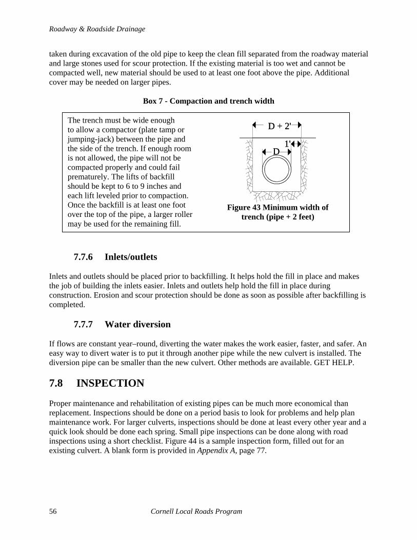
Roadway & Roadside Drainage
taken during excavation of the old pipe to keep the clean fill separated from the roadway material and large stones used for scour protection. If the existing material is too wet and cannot be compacted well, new material should be used to at least one foot above the pipe. Additional cover may be needed on larger pipes.
Box 7 - Compaction and trench width
D + 2'
1'D
D + 2'
1'D
Figure 43 Minimum width of
trench (pipe + 2 feet)
The trench must be wide enough to allow a compactor (plate tamp or jumping-jack) between the pipe and the side of the trench. If enough room is not allowed, the pipe will not be compacted properly and could fail prematurely. The lifts of backfill should be kept to 6 to 9 inches and each lift leveled prior to compaction. Once the backfill is at least one foot over the top of the pipe, a larger roller may be used for the remaining fill.
7.7.6 Inlets/outlets Inlets and outlets should be placed prior to backfilling. It helps hold the fill in place and makes the job of building the inlets easier. Inlets and outlets help hold the fill in place during construction. Erosion and scour protection should be done as soon as possible after backfilling is completed.
7.7.7 Water diversion If flows are constant year–round, diverting the water makes the work easier, faster, and safer. An easy way to divert water is to put it through another pipe while the new culvert is installed. The diversion pipe can be smaller than the new culvert. Other methods are available. GET HELP. 7.8 INSPECTION Proper maintenance and rehabilitation of existing pipes can be much more economical than replacement. Inspections should be done on a period basis to look for problems and help plan maintenance work. For larger culverts, inspections should be done at least every other year and a quick look should be done each spring. Small pipe inspections can be done along with road inspections using a short checklist. Figure 44 is a sample inspection form, filled out for an existing culvert. A blank form is provided in Appendix A, page 77.
56 Cornell Local Roads Program
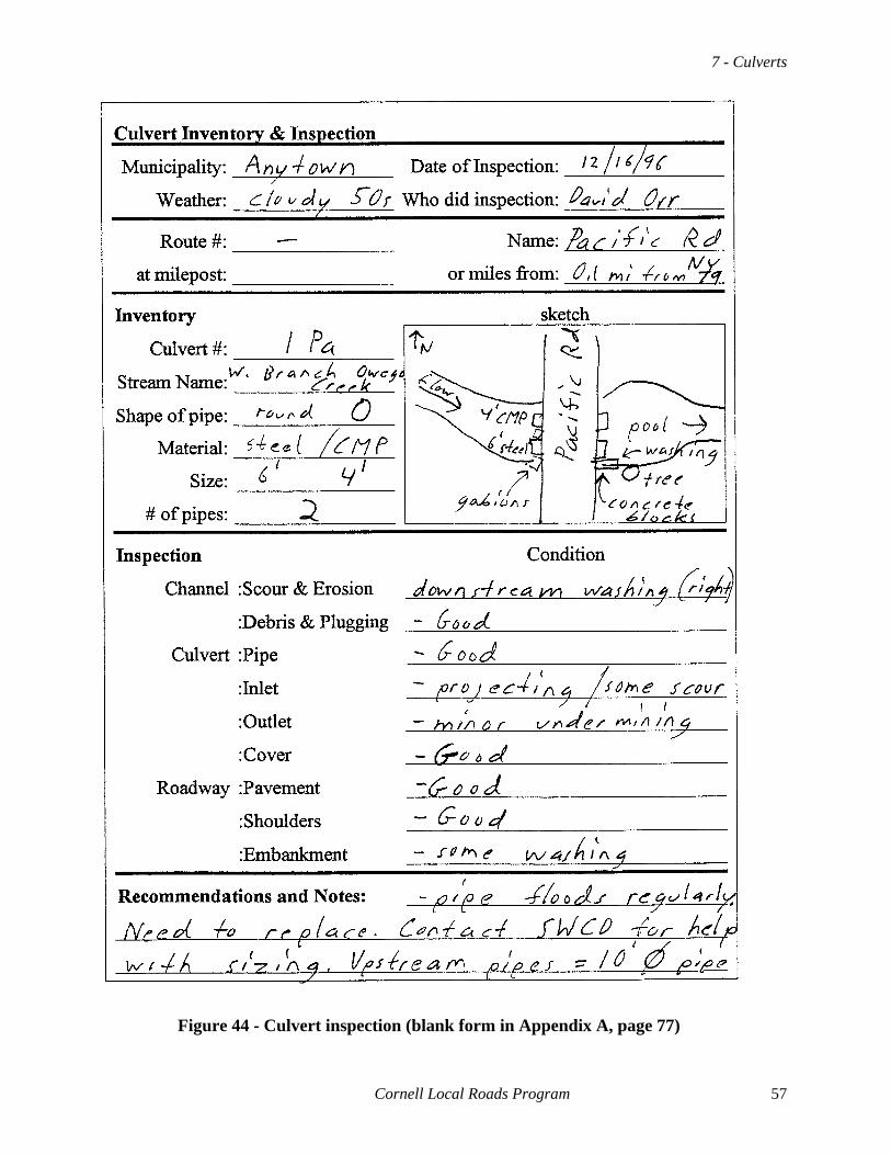
7 - Culverts
Cornell Local Roads Program 57
Figure 44 - Culvert inspection (blank form in Appendix A, page 77)

Roadway & Roadside Drainage
The following items are special problems that should be checked for each culvert.
7.8.1 Piping Piping is the flow of water along the outside of the pipe, which can remove materials and eventually cause the pipe to fail by blowout or crushing due to lack of support from the surrounding soil. Look for erosion along the pipe at the upper end, evidence of fines leaking through joints, and flow of water outside of the pipe in the downstream end. Corrective action includes: Installing a headwall and cutoff wall, placing a grouted protective layer on the upstream side, or using a fly-ash mixture to help fill the voids caused by piping.
7.8.2 Blowouts Blowouts occur when a pipe under pressure is pushed right out of the fill of the roadway. Excessive vibrations caused by traffic, and flow of water along with piping can cause a loss of support. The pressure of water on the upstream side can push the entire pipe. The force of water under a moderate head can push fill and pipes a long way downstream. Obviously a blowout is not an inspectable item. By the time you see the blowout, it is too late. Look for piping, excessive backwater and cracking of the soil near the inlet and outlet. This may indicate the pipe could blowout. Corrective action includes: Installing a headwall and/or a cutoff wall, anchoring the pipe with deadmen, or reducing vibration problems by installing an inlet to reduce turbulence in the water.
7.8.3 Washouts Washouts occur when a culvert is washed away by overtopping of the roadway. The capacity of the pipe has been exceeded for any number of reasons. Look for evidence of flood marks above the roadway elevation, scour on the downstream slope and shoulder of the road, or debris that may cause plugging. Corrective action includes: Protecting the banks from washing with stones or grout, increasing the pipe size, providing a debris catcher upstream or at the inlet, or increasing the head to provide more capacity.
58 Cornell Local Roads Program
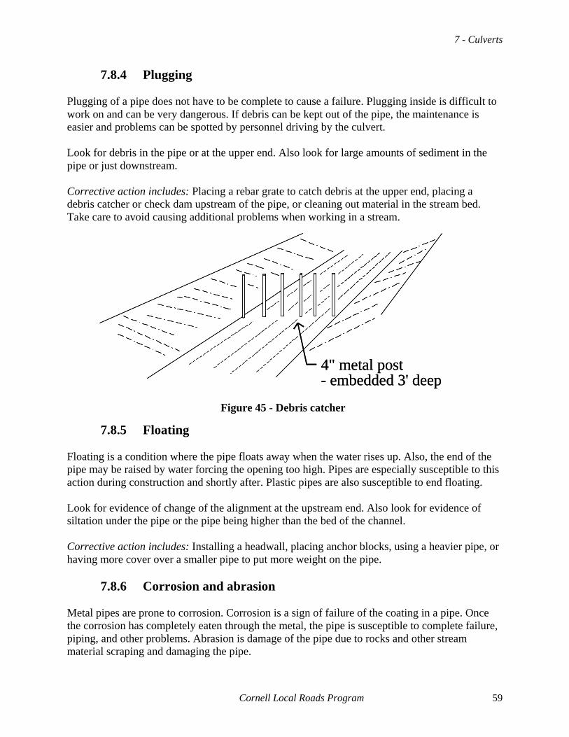
7 - Culverts
7.8.4 Plugging Plugging of a pipe does not have to be complete to cause a failure. Plugging inside is difficult to work on and can be very dangerous. If debris can be kept out of the pipe, the maintenance is easier and problems can be spotted by personnel driving by the culvert. Look for debris in the pipe or at the upper end. Also look for large amounts of sediment in the pipe or just downstream. Corrective action includes: Placing a rebar grate to catch debris at the upper end, placing a debris catcher or check dam upstream of the pipe, or cleaning out material in the stream bed. Take care to avoid causing additional problems when working in a stream.
4" metal post- embedded 3' deep4" metal post- embedded 3' deep
7.8.5 Floating
Figure 45 - Debris catcher
Floating is a condition where the pipe floats away when the water rises up. Also, the end of the pipe may be raised by water forcing the opening too high. Pipes are especially susceptible to this action during construction and shortly after. Plastic pipes are also susceptible to end floating. Look for evidence of change of the alignment at the upstream end. Also look for evidence of siltation under the pipe or the pipe being higher than the bed of the channel. Corrective action includes: Installing a headwall, placing anchor blocks, using a heavier pipe, or having more cover over a smaller pipe to put more weight on the pipe.
7.8.6 Corrosion and abrasion Metal pipes are prone to corrosion. Corrosion is a sign of failure of the coating in a pipe. Once the corrosion has completely eaten through the metal, the pipe is susceptible to complete failure, piping, and other problems. Abrasion is damage of the pipe due to rocks and other stream material scraping and damaging the pipe.
Cornell Local Roads Program 59

Roadway & Roadside Drainage
Look for rust and evidence of loss of coating in metal pipe. Look for damage to the surface of concrete and plastic pipes. Also, look for large amounts of large rocks and debris downstream. Corrective action includes: Paving the bottom of the pipe with concrete, lining the pipe with a small pipe, or replacement of the pipe. Abrasion may be reduced by installation of a debris catcher or check dam. Care should be taken to insure a lined pipe will have adequate flow capacity.
7.8.7 End crushing The ends of flexible pipes are prone to crushing due to maintenance activities or debris flows. This will reduce capacity and can lead to other problems such as plugging. Look for bent ends and evidence of large debris near the inlet. Advise crews to be very careful around the ends and mark the ends with signs or markers. Corrective action includes: Cutting off bent material, rebending ends to original shape, replacing end section of the pipe.
7.8.8 Other Other special concerns include freezing of the pipe, joint failures, and damage by maintenance forces. Frozen pipes need to be thawed by steam or nature and are most common when the ends are damaged or in very flat–sloped corrugated pipes. Joint failures can lead to piping, complete failure, and settlement at the surface of the roadway. Damage by maintenance crews should be fixed as soon as possible. 7.9 MAINTENANCE Many maintenance activities can be done to extend the life of a culvert. Some of the common maintenance tasks are flushing, lining, cleaning debris, and extending ends.
7.9.1 Clearing debris from ends Each spring a crew should check each culvert and clean any trees and debris from the inlets and outlets, debris racks, and check dams. Pipes without debris protection should be checked for debris in the pipe during the winter BEFORE the spring thaw.
60 Cornell Local Roads Program
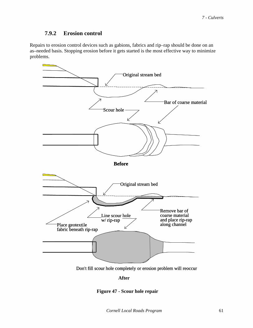
7 - Culverts
7.9.2 Erosion control Repairs to erosion control devices such as gabions, fabrics and rip–rap should be done on an as–needed basis. Stopping erosion before it gets started is the most effective way to minimize problems.
Scour hole
Original stream bed
Bar of coarse material
Before
Scour hole
Original stream bed
Bar of coarse material
Before
Line scour holew/ rip-rap
Original stream bed
Remove bar of coarse materialand place rip-rapalong channelPlace geotextile
fabric beneath rip-rap
Don't fill scour hole completely or erosion problem will reoccur
Line scour holew/ rip-rap
Original stream bed
Remove bar of coarse materialand place rip-rapalong channelPlace geotextile
fabric beneath rip-rap
Don't fill scour hole completely or erosion problem will reoccur After
Figure 47 - Scour hole repair
Cornell Local Roads Program 61

Roadway & Roadside Drainage
7.9.3 Flushing Flushing pipe with a pressure hose should be a scheduled activity. Many agencies perform the work in the spring to clean up after the winter. Some do it in the late fall before winter. Remember, the most likely time of the year for heavy flows is during the spring thaw. Pipes should be flushed prior to that period if possible. However, a good maintenance schedule to keep pipe relatively clean all year-round is the most effective way to maintain pipes.
7.9.4 Minor repairs Minor repairs to bent metal ends, spalled concrete, or other problems can be done at any time. They should be scheduled with other activities.
7.9.5 Lining Lining of pipes can be done when a pipe is near the end of its effective life but the capacity is adequate to allow lining. Lining is usually done on pipes with a fairly high cover that would be expensive to replace and time consuming to repair. Lining is an effective option, but if you have any questions, GET HELP.
7.9.6 Extending Extending pipes is done to reduce steepness of slopes, reduce scour, or when a road is widened. Two general rules should be kept in mind before extending is done. One, the joints between the old and new pipe must be of high quality. Two, the capacity of the pipe to handle flows must be checked.
62 Cornell Local Roads Program

8 - Ditches
8 - DITCHES 8.1 PURPOSES Ditches serve several needs at the same time. We need to understand the reasons for ditches so we can understand how to maintain and construct them. Ditches carry collected surface water. They are used to help keep roads, fields, and all kinds of developments dry by moving water from one location to another. For roads and streets, three main purposes are found.
8.1.1 Roadside A roadside ditch collects surface runoff from the pavement and carries it parallel to the road to a channel or culvert where the water can be taken away from the road. It also intercepts surface water before it gets to the road surface.
8.1.2 Diversion Diversion ditches can be parallel to the roadway, but do not have to be. They divert excess water before it gets to the roads, a slope, or other feature of the road. They differ from roadside ditches in two ways. One, they do not collect roadway runoff. Two, they are only in place to divert excess water.
8.1.3 Lower water table Both kinds of ditches can be used to lower the water table. In addition, they can be used to allow free water to drain from an open base under the roadway. However, that should not be the primary function. They will not dry out a base material with too many fines.
8.1.4 Farm vs. highway needs One of the problems faced in rural New York is the large number of ditches built for farmers and not for highways. Highway ditches are relatively shallow and should have flat slopes. If the ditch is too deep, it can trap vehicles and cause instability problems for the roadway. Work with farmers and others to make sure they understand the reasons for highway ditches. Help the farmer where possible, but remember lowering the ditches and failure to keep slopes flat, can increase liability.
Cornell Local Roads Program 63
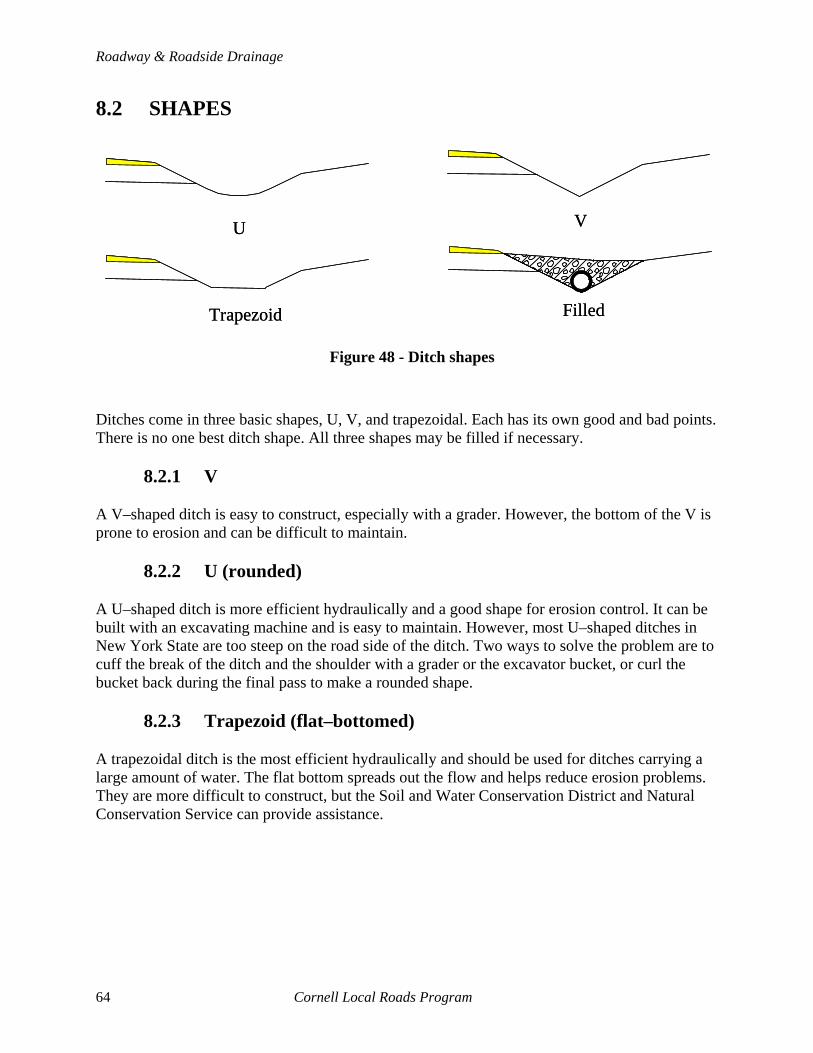
Roadway & Roadside Drainage
8.2 SHAPES
U V
Trapezoid Filled
U V
Trapezoid Filled
Figure 48 - Ditch shapes
Ditches come in three basic shapes, U, V, and trapezoidal. Each has its own good and bad points. There is no one best ditch shape. All three shapes may be filled if necessary.
8.2.1 V A V–shaped ditch is easy to construct, especially with a grader. However, the bottom of the V is prone to erosion and can be difficult to maintain.
8.2.2 U (rounded) A U–shaped ditch is more efficient hydraulically and a good shape for erosion control. It can be built with an excavating machine and is easy to maintain. However, most U–shaped ditches in New York State are too steep on the road side of the ditch. Two ways to solve the problem are to cuff the break of the ditch and the shoulder with a grader or the excavator bucket, or curl the bucket back during the final pass to make a rounded shape.
8.2.3 Trapezoid (flat–bottomed) A trapezoidal ditch is the most efficient hydraulically and should be used for ditches carrying a large amount of water. The flat bottom spreads out the flow and helps reduce erosion problems. They are more difficult to construct, but the Soil and Water Conservation District and Natural Conservation Service can provide assistance.
64 Cornell Local Roads Program

8 - Ditches
8.2.4 Filled ditches Sometimes ditches are filled in with large stone to make them safer for traffic when there is limited room to widen a ditch. These ditches act very similarly to trench drains. The flow is carried in the voids between the stone fill. A perforated pipe should be placed at the bottom to ensure the ditch lasts as long as possible before silting occurs between the stones. This concentrates the flow and reduces the amount of siltation in the stones. A fabric should be placed on the road side of the ditch as a minimum to keep material from the roadway from washing into the ditch. 8.3 SIDE SLOPES Side slopes should be as flat as possible for the traveling public. Slopes steeper than 1:2 to vertical horizontal may be unstable and require guiderail to keep errant vehicles out of them. Slopes of 1:3 are considered good. See Chapter 9, Erosion and Slopes for more on slopes themselves.
8.3.1 Maintenance Maintenance of ditch sides is much easier when the slopes are 1:2 or flatter. They can be mowed and maintained very easily. A properly built ditch will help keep itself clean and will only need mowing and some minor cleaning on a routine basis.
8.3.2 Stability Unstable ditches may be stabilized by filling the ditch with stone as above or lining the sides with stabilizing materials. See below for a discussion of the pros and cons of each material.
8.3.3 Offset The offset to the bottom of a ditch should be determined by the depth needed in the ditch and the side slope. Too many ditches are deepened in place without regard to the changes in slope of the roadside slope. Ditches need to get wider as they get deeper, and the backside of the ditch should be stable. Difficulty with a narrow Right-of-way may force a ditch to be filled with stone or lined for stability.
Before Poor Right
deepersteeper same foreslope
same depthBefore Poor Right
deepersteeper same foreslope
same depth
Figure 49 - Changes in slope in a ditch cleaned at the same offset
Cornell Local Roads Program 65

Roadway & Roadside Drainage
8.4 FALL Typically, ditches will follow the natural contours of the land. If the fall is less than one percent the flow of water in the ditch may be too slow and it may fill with sediment. If the fall is too great, erosion may destroy any lining material. A maximum of five percent is generally used. If the slope is too great, check dams may be used to help reduce velocities and control erosion.
8.4.1 Velocity The steeper the ditch, the faster the velocity. The maximum allowable velocity of water over most soils in New York State is less than that of both vegetative cover and man–made cover, such as rip–rap.
8.4.2 Check dams If the ditch is too deep, a series of check dams can be placed to reduce the velocity of the water flow. Check dams can be made of gabions, wood, concrete, or steel. The two major problems with most check dams are failure to allow for dissipation of the flow as it drops over the dam, and failure to bed the dam deep enough to keep it from being eroded in a severe storm.
5% max slopebetween dams
Natural slope
Gabions, concrete, rip-rap, wood, etc.
Scour pad downstream
5% max slopebetween dams
Natural slope
Gabions, concrete, rip-rap, wood, etc.
Scour pad downstream
Figure 50 - Good check dam showing deep bedding and downstream pad
8.5 LINING MATERIALS Before we clean or construct a ditch we need to decide what the ditch will be lined with when we are done. Table 12 shows various lining possibilities and discusses the pros and cons of each. Erosion resistance and water retardance are the two main factors that affect ditch performance. The less erodible a material is, the less maintenance needed and the greater the allowable fall. Water retardance should be kept low to improve flow capacity and reduce sedimentation problems. Remember that a material with a low–water retardance will have greater velocity of flow and may be more prone to erosion problems. The table lists the relative erodibility of common ditch lining materials. Choice of materials is based upon cost and maintenance factors.
66 Cornell Local Roads Program
8 - Ditches
Table 12 - Ditch lining materials
high
low
Erodibility Earth Earth bottom/grassed sides Grassed (mowed) Weeds & grass (unmowed) Stone bottom/grassed sides Fabric Stone bottom & sides Concrete
Water retardance Concrete Fabric Earth Stone bottom & sides Earth bottom/grassed sides Stone bottom/grassed sides Grass (mowed) Weeds & grass (unmowed)
low
high
Notes:
• Earth Severe erosion problems can occur. Also, the ditch will eventually fill with weeds and grass if not seeded or stabilized.
• Earth bottom
Condition of ditch after cleaning. Needs to be seeded to keep weeds from growing and causing a retardance problem.
• Fabric
Only certain special fabrics (geotextiles) can be used in this application. Contact CLRP or SWCD for advice.
• Concrete
Concrete and asphalt ditches are prone to heaving and undermining. They require vigilant maintenance as well as quality construction.
8.6 CAPACITY AND DEPTH Most ditches have more capacity than they need. The needed capacity of most roadside ditches is very small. Only when the ditch is carrying a diversion flow or is very long between culvert pipes do you need to be concerned about capacity. In such cases, GET HELP. Typically, historical perspective is enough to determine if the ditch is large enough. As a rule of thumb, the ditch should be 12 inches below the bottom of the subgrade.
Cornell Local Roads Program 67

Roadway & Roadside Drainage
8.6.1 Volume
The volume of water to be carried is usually controlled by the upstream culvert. The SWCD or whomever designs a new pipe can determine the ditch size needed. Most ditches have a much larger area than the culvert just upstream. The velocity is usually the major concern. Too much velocity can cause erosion.
U V
Trapezoid
Scour problems can occurat pipe inlets and outlets
U V
Trapezoid
Scour problems can occurat pipe inlets and outlets
Figure 51 - Ditch versus pipe area
8.6.2 Daylight base
The ditch also helps drain the base of the roadway. The bottom of the ditch should be below the base of the roadway. 8.7 MAINTENANCE Maintenance of ditches needs to be done on a regular basis. Two very different items are the most common maintenance techniques, cleaning and reshaping. Be sure to do the right maintenance. Any ditch work does two undesirable things if not managed and repaired. The work exposes the gravel to erosion. Also, it may change the depth of the ditch to an undesirable depth.
8.7.1 Cleaning Cleaning ditches involves removal of sediment and vegetation from the bottom of the ditch. Very small amounts of material should be removed. Cleaning should be checked by walking the ditch after the cleaning. A small amount of annual and perennial grass seed can be spread ahead of the person checking the work. Their walking will bed the seed into the exposed ground. Cleaning the ditch does not involve changing the width or depth of the ditch. If too deep, the ditch may become a hazard to motorists.
68 Cornell Local Roads Program
8 - Ditches
8.7.2 Reshaping Removing large amounts of material and widening or deepening the ditch is reshaping. Reshaping is often referred to as cleaning. Reshaping should be laid out prior to beginning work, and should be checked by the foreman with a hand level to make sure too much material is not removed. The depth should be a constant fall with the bottom of the ditch on the flow line between culverts. If no culvert is at either end the ditch should have a constant fall of approximately 1–2 percent. The depth cannot be lower than the flow line between culverts at the upper and lower end of the ditch. If it is, the ditch will fill in rapidly with undesirable material. 8.8 GENERAL TIPS
• Always clean ditches uphill • Place erosion protection or seeding every day and before any rain • Have erosion material ready before starting job (in case of rain) • When in doubt, GET HELP
Cornell Local Roads Program 69


9 - Slopes & Erosion Control
9 - SLOPES AND EROSION CONTROL 9.1 HOW TO STOP EROSION Stopping erosion is difficult. Keeping erosion from occurring in the first place is usually more successful. Many of the maintenance activities performed on roads and streets would be unnecessary if erosion was controlled. As an example, stopping erosion from occurring at the top of a hill will reduce the ditching at the bottom of the hill. Approximately 30 tons of material can be eroded from a mile of ditches before you can see the damage! To remove and replace 30 tons of material is a lot of work. Also, you need to be concerned about erosion during construction and maintenance work. The work can cause additional erosion. 9.2 TYPES OF EROSION Three types of erosion are common: surface, rill, and galley. Different soils erode differently. For most highway materials you can be sure of two things. One, unprotected materials will erode and cause sedimentation. Two, the flatter the slope the fewer erosion problems occur.
• Surface Surface or sheet erosion occurs when rainfall dislodges soil on the surface of material, and the water plus soil flows in sheets. The washing of shoulders is often started by this process.
• Rill Rill erosion occurs when the velocity of the flow is great enough to dislodge soil in addition to that dislodged by rainfall. Rill erosion is typified by the narrow little channels that form in banks and slopes that are not protected from erosion.
• Gully Gully erosion occurs when rill erosion combines and concentrates the flow of runoff into gullies. Washouts between pavement and shoulders are usually gully erosion.
Cornell Local Roads Program 71

Roadway & Roadside Drainage
Raindrop erosionSurface erosion
Rill erosionGully erosion
Raindrop erosionSurface erosion
Rill erosionGully erosion
Figure 52 - Types of erosion
9.3 SEDIMENTATION All of the material removed by erosion is deposited at some location downstream from the erosion. This process of sedimentation usually occurs where a change in the speed of the flow occurs. Filling of culverts, ditches, streambeds, and even lakes is a result of sedimentation. Stopping erosion will eliminate or reduce many of the problems associated with poor drainage. 9.4 SLOPES Even very flat ground erodes. The reason you do not notice the erosion is that sedimentation occurs at the same location as the erosion. Steep terrain erodes very quickly. You need to reduce erosion problems. In addition, for slopes you have to be concerned about three factors: stability, safety, and maintenance.
Slope
CL
5' 11
2 311
5'10'
15'
Slope
CL
5' 11
2 311
5'10'
15'
Figure 5 - Slopes
72 Cornell Local Roads Program
9 - Slopes & Erosion Control
9.4.1 Stability Most highway materials are stable at slopes of 1:2 or flatter. Slopes steeper than 1:2 are more prone to erosion and washouts. If saturated, the entire slope may fail.
9.4.2 Safety Slopes along the edge of roads, including ditches and banks, need to be kept fairly flat to allow errant vehicles a safe place to drive. Slopes of 1:3 or flatter are considered safe. If the slope is less than 3 feet high a 1:2 slope is acceptable. More information on roadside safety can be found in the Cornell Local Roads Program’s manual, Road Safety Fundamentals.
9.4.3 Maintenance Mowing slopes is the most common maintenance technique. If slopes are 1:2 or flatter, the mowing crews can easily mow the slope. Minor repairs may be needed to fix small washouts and erosion.
9.4.4 Options If a slope is too steep, several items need to be examined to repair the problem:
• Stabilize Unstable slopes can be stabilized by use of geotextiles or other earth reinforcement materials. If you have a high steep slope that is showing signs of distress, GET HELP.
• Retaining walls Use of gabions, concrete, and block retaining walls may be needed on very steep slopes or to help stabilize the toe of an existing slope. If a slope is so steep the erosion mitigations listed below will not work, a retaining wall may be needed. GET HELP to determine the best course of action.
• Signing Slopes steeper than 1:3 (1:2 for 3 or fewer feet in height) need to be protected. As a minimum, signs should be used to delineate the slope and warn motorists of the hazard. See Chapter 17B New York Code of Rules and Regulations (NYCRR) for future information.
• Guiderail Guiderail should be used on steep slopes. It needs to be installed and used correctly as part of an overall plan to upgrade the roads. The NYSDOT publication, Guiderail III, has valuable information about the use of guiderail to protect slopes.
Cornell Local Roads Program 73

Roadway & Roadside Drainage
9.5 EROSION MITIGATION To protect the exposed surfaces after construction or due to minor failures, mitigation should be performed. The objective of the repairs is to eliminate the start of erosion caused by rainfall and melting snow. Several different materials can be used to reduce or eliminate erosion problems. The most common are discussed below. The erosion material works by absorbing the energy of a falling drop of water. Erosion due to steep slopes (steeper than 1:2) is difficult to stop. The velocity of the water flowing over the protective material can start erosion.
9.5.1 Earth Earth erodes easily and is not stable. It should not be left exposed for even a short period of time.
9.5.2 Vegetation Vegetation including grass, bushes, and trees can be planted to reduce erosion. The Soil and Water Conservation District (SWCD) and Natural Resources Conservation Service (NRCS) have information and can provide assistance to place the best vegetation for a given problem. A general rule of thumb is use vegetation if possible. It is cheaper than other methods and is more pleasing to the eye.
9.5.3 Stones/rip-rap Fairly common to protect high and steep banks, stones, or rip-rap can eliminate many erosion problems. A separation geotextile should be installed on the slope prior to placing of the stone or the stone will shift and settle and eventually fail to protect the slope. The size of the material does not have to be large (angular gabion stone is very effective) unless a large volume of water is expected. Then the blanket of stones should be made with larger size rock.
Slope 1:2 typical
stream bed
toe of slope
2'
2' (min)
minimum size oftoe is 1 1/2 timesthe largest stones
Rip-rap usually 1' minimum size.Chink surface with smaller stones.Grout may be needed on steep slopes.
geotextile fabricbetween rip-rap and fill
Tuck 6" offabric into slope
21
Slope 1:2 typical
stream bed
toe of slope
2'
2' (min)
minimum size oftoe is 1 1/2 timesthe largest stones
Rip-rap usually 1' minimum size.Chink surface with smaller stones.Grout may be needed on steep slopes.
geotextile fabricbetween rip-rap and fill
Tuck 6" offabric into slope
21
Slope 1:2 typical
stream bed
toe of slope
2'
2' (min)
minimum size oftoe is 1 1/2 timesthe largest stones
Rip-rap usually 1' minimum size.Chink surface with smaller stones.Grout may be needed on steep slopes.
geotextile fabricbetween rip-rap and fill
Tuck 6" offabric into slope
21
Figure 54 - Placement of rip-rap on a slope
74 Cornell Local Roads Program
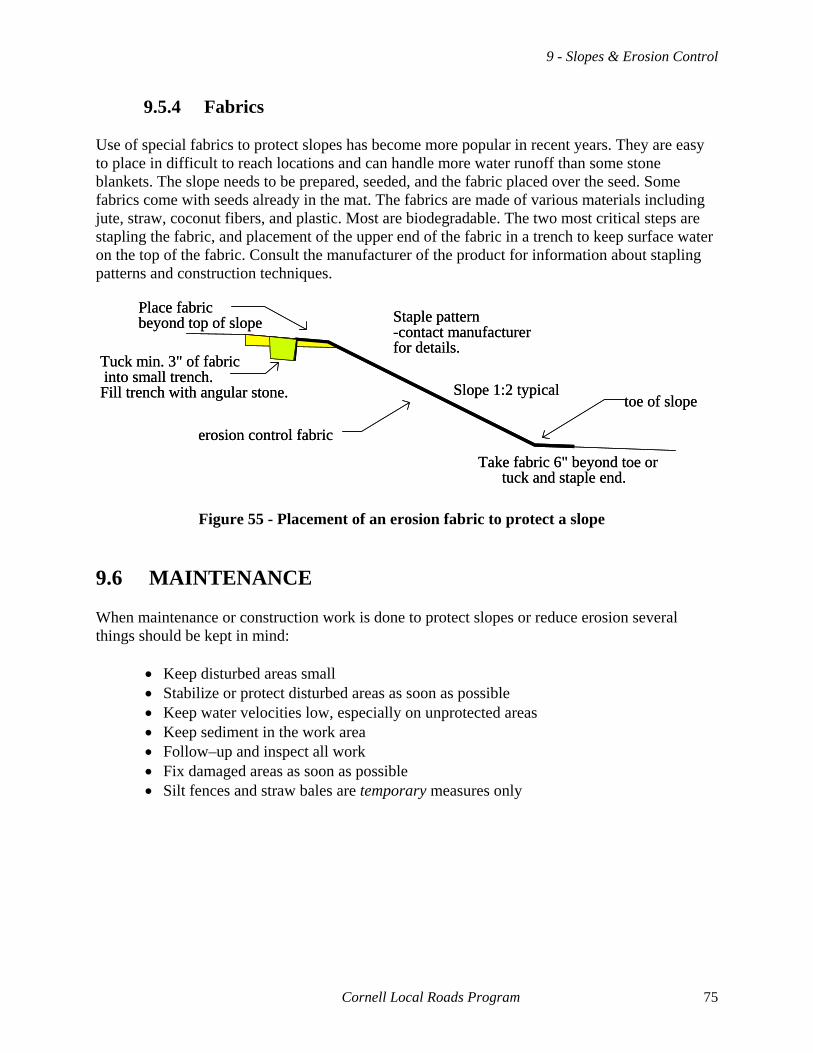
9 - Slopes & Erosion Control
9.5.4 Fabrics Use of special fabrics to protect slopes has become more popular in recent years. They are easy to place in difficult to reach locations and can handle more water runoff than some stone blankets. The slope needs to be prepared, seeded, and the fabric placed over the seed. Some fabrics come with seeds already in the mat. The fabrics are made of various materials including jute, straw, coconut fibers, and plastic. Most are biodegradable. The two most critical steps are stapling the fabric, and placement of the upper end of the fabric in a trench to keep surface water on the top of the fabric. Consult the manufacturer of the product for information about stapling patterns and construction techniques.
Slope 1:2 typicaltoe of slope
erosion control fabric
Tuck min. 3" of fabricinto small trench.Fill trench with angular stone.
Place fabricbeyond top of slope
Take fabric 6" beyond toe ortuck and staple end.
Staple pattern-contact manufacturerfor details.
Slope 1:2 typicaltoe of slope
erosion control fabric
Tuck min. 3" of fabricinto small trench.Fill trench with angular stone.
Place fabricbeyond top of slope
Take fabric 6" beyond toe ortuck and staple end.
Staple pattern-contact manufacturerfor details.
9.6 MAINTENANCE
Figure 55 - Placement of an erosion fabric to protect a slope
When maintenance or construction work is done to protect slopes or reduce erosion several things should be kept in mind:
• Keep disturbed areas small • Stabilize or protect disturbed areas as soon as possible • Keep water velocities low, especially on unprotected areas • Keep sediment in the work area • Follow–up and inspect all work • Fix damaged areas as soon as possible • Silt fences and straw bales are temporary measures only
Cornell Local Roads Program 75


Appendix A - Culvert Inspection
Culvert Inventory & Inspection
Municipality: Date of inspection:
Weather: Who did inspection:
Route #: Name:
at milepost: or miles from:
Inventory sketch
Culvert #:
Stream Name:
Shape of pipe:
Material:
Size:
# of pipes:
Inspection condition
Channel: Scour & erosion
: Debris & plugging
Culvert: Pipe
: Inlet
: Outlet
: Cover
Roadway: Pavement
: Shoulders
: Embankment
Recommendations and notes:
____________________________________________________________________________
Cornell Local Roads Program 77

Appendix B - Temporary Easement
TEMPORARY EASEMENT CONSENT TO ENTER AND DO WORK
I/We, ______________________________________[Name(s) of property owner(s)],
for the consideration of $1 (payment waived) grant to TOWN OF ANYTOWN, the right to
enter my/our property at _______________________________ [Location of property] to do
the following work in connection with the TOWN OF ANYTOWN highway system:
____________________________________________________________________________
____________________________________________________________________________
____________________________________________________________________________
____________________________________________________________________________
The ______________ [Name of municipality] may enter upon the property described above
within ________ [Number of] days/weeks/months (circle one) of the date of this temporary
easement, after which this easement shall automatically terminate.
The ______________ [Name of municipality] will cause no unreasonable damage to the land
during the work and will restore the land to substantially the same condition as it was before
such work to the extent practical in keeping with the purpose of the work.
PROPERTY OWNER(S)
Date: _____/______/_____ _____/_____/_____
Owner’s signature(s) ____________________ ______________________
Property owner’s name(s) ____________________ ______________________
Address ____________________ ______________________
____________________ ______________________
Phone (_____)______________ (_____)_________________
___________________________ [NAME OF MUNICIPALITY REPRESENTATIVE]
Date: ______/______/______
Signature ______________________
Municipal representative name ______________________
Title ______________________
78 Cornell Local Roads Program

Appendix C - Bibliography
AASHTO Maintenance Manual, American Association of State Highway and Transportation Officials, 1987 Asphalt Pavement Repair Manual of Practice, SHRP–H–348, 1993 Basics of a Good Road, Cornell Local Roads Program, 1996, CLRP #96–5 Concrete Pipe Design Manual, American Concrete Pipe Association, 1987 Culvert Design, Reagan Engineering Associates, 1996 Culvert Inspection Manual, FHWA–IP–86–2 Culvert Repair and Rehabilitation, Reagan Engineering Associates, 2002 Culvert Repair Practices Manual, FHWA–RD–94–096 Drainage, National Association of County Engineers, Volume XIV, 1972 Drainage Design Manual for New York State, Cornell University Department of Agricultural Engineering, 1974 Drainage, Drainage, Drainage, Maine Local Roads Center, 1993 Drainage of Surface Waters, Darrell Harp, New York State Department of Transportation, 1996 Effects of Drainage Design on Road Performance, Vermont Local Roads Program, 1984 Erosion and Sediment Control Field Notebook, New York Contractors—Soil and Water Conservation Society A Guide to: Conservation Plantings on Critical Areas for New York State, USDA, Soil Conservation Service, Syracuse, NY, June 1991 Geotextile Selection and Installation Manual for Rural and Unpaved Roads, FHWA–RT–89–050 Gravel Quick Bite, Cornell Local Roads Program, Technical assistance on–line, www.clrp.cornell.edu/TechAssistance/tipSheets.htm Gravel Roads Maintenance and Design Manual, South Dakota LTAP Center, 2000
Cornell Local Roads Program 79
Roadway & RoadsideDrainage
Guidelines for Geometric Design of Very Low–Volume Local Roads, AASHTO, 2001 Guiderail III, New York State Department of Transportation, Albany, 1990 Handbook of Culvert and Drainage Practice, The Lakeside Press, R. R. Donnelley & Sons Co., 1937 Highway Drainage Guidelines, American Association of State Highway and Transportation Officials, 1992 Highway Superintendents Roads and Water Quality Handbook, Cornell Cooperative Extension, 1996 Hydraulic Design of Highway Culverts, FHWA–IP–85–15 Managing Nuisance Beavers Along Roadsides: A Guide for Highway Departments, Cornell Local Roads Program, 2000 New York Guidelines for Urban Erosion and Sediment Control, Soil and Water Conservation Society, 1991 Nuggets and Nibbles, Cornell Local Roads Program, Volume XV #3, 1996 Road Design and Maintenance Handbook: Techniques for Reducing Flood Damage to Local Roads, Vermont Local Roads Program, 1995 Road Drainage, Transportation Information Center, UW–Madison, Department of Engineering Professional Development, 432 N. Lake St., Madison, WI 53706 Road Safety Fundamentals, Cornell Local Roads Program, 2002, CLRP #02–7 Roadway and Right–of–Way Maintenance, New York State Department of Environmental Conservation-Division of Water, 1994 Soil Erosion: The Work of Uncontrolled Water, U. S. Department of Agriculture Soil Conservation Service, 1971 Standard Specifications: Construction and Materials, New York State Department of Transportation, 2001 Summary of New York State Drainage Law, Cornell Cooperative Extension Information Bulletin 195, 1983 Surveying Methods for Local Highway Departments, Cornell Local Roads Program, CLRP #94–5 Upgrading Your Roads, Cornell Local Roads Program, Report #92–6
80 Cornell Local Roads Program

VIDEOS (contact the Cornell Local Roads Program to borrow the following videotapes) Basic Principles for Proper Installation of Corrugated Steel Drainage Structures, NCSPA Frost Action in Soils, CRREL Weather and Loads: The Effect They Have on Roads, Minnesota LRRB/Minnesota DOT
Cornell Local Roads Program 81
Appendix D - Resources
American Association of State Highway and Transportation Officials
(AASHTO) 444 N. Capital Street, NW (Suite 225)
Washington, D. C. 20001 (202) 624–5800
American Concrete Pipe Association
222 W. Las Calinas Blvd. Suite 641
Irving, TX 75062 (972) 506–7216
American Public Works Association
(APWA) Kansas City, MO (816) 472–6100
American Road and Transportation
Builders Association (ARTBA) The ARTBA Building
1010 Massachusetts Ave., NW Washington, DC 20001
(202) 289–4434
Association of Towns 146 State Street
Albany, NY 12207 (518) 465–7933
Better Roads Magazine
(subscription free to public works officials) PO Box 558
Park Ridge, IL 60068 (312) 693–7710
Cornell Local Roads Program
416 Riley–Robb Hall Cornell University
Ithaca, NY 14853–5701 (607) 255–8033
Corrugated Polyethylene Pipe Association
1446 Durham St. Oakville, Ontario, Canada LGJ2P3
(800) 510–CPPA
Department of Environmental Conservation 625 Broadway
Albany, NY 12233–3508 (518) 402–9167
Dig Safely New York
3650 James Street Syracuse, NY 13206
(see page 33 for phone numbers)
National Association of County Engineers (NACE)
440 First Street, NW Washington, D.C. 20001
(202) 393–5041
New York State Association of Town Superintendents of Highways, Inc.
4294 Crains Mills Road Truxton, NY 13158
(607) 842–6458
New York State Conference of Mayors and other Municipal Officials (NYCOM)
119 Washington Avenue Albany, NY 12210
(518) 463–1185
New York State County Highway Superintendents’ Association
29 Elk Street, Suite 200 Albany, NY 12207
(518) 465–1694
Public Works Magazine (free to public works officials)
Box 688 Ridgewood, NJ 07451
(201) 445–5800
Roads and Bridges Magazine (subscription free to public works officials)
380 E. Northwest Highway Des Plaines, IL 60016–2282
(708) 298–6622
82 Cornell Local Roads Program

Appendix E - NYSDOT Regional Offices
Region 1 84 Holland Avenue Albany, NY 12208
(518) 474–6178
Region 2 207 Genesee Street Utica, NY 13501 (315) 793–2447
Region 3
333 E. Washington Street Syracuse, NY 13202
(315) 428–4351
Region 4 1530 Jefferson Road Rochester, NY 14623
(716) 272–3300
Region 5 125 Main Street
Buffalo, NY 14203 (716) 847–3238
Region 6
107 Broadway Hornell, NY 14843
(607) 324–8404 30 West Main Street
Region 7 317 Washington Street Watertown, NY 13601
(315) 785–2333
Region 8 4 Burnett Boulevard
Poughkeepsie, NY 12603 (914) 431–5750
Region 9
State Office Building 44 Hawley Street
Binghamton, NY 13901 (607) 721–8116
Region 10
State Office Building Veterans Highway
Hauppauge, NY 11788 (516) 952–6632
Region 11
Hunters Point Plaza 47–40 21st Street
Long Island City, NY 11101 (718) 482–4526
Hunters Point Plaza Long Island City, NY 11101
(718) 482–4533
Main office information: New York State Department of Transportation 5–504 Harriman State Office Campus 1220 Washington Avenue Albany, New York 12232 (518) 457–4422 Web page: http://www.dot.state.ny.us/info/info.html#org NYSDOT Plan Sales Office: For contract specifications contact (518) 457–2124, or visit the Web site: www.dot.state.ny.us/pubs/publist.html
Cornell Local Roads Program 83

Appendix F - NYS Soil and Water Conservation Districts
NYS Soil and Water Conservation Committee (518) 457–7923
Albany (518) 765–7923 Allegany (716) 268–7831 ext. 102 Broome (607) 724–9268 Cattaraugus (716) 699–2326/2327 Cayuga (315) 252–4171/0793 Chautauqua (716) 664–2355 Chemung (607) 739–4392/2009 Chenango (607) 334–4632/8634 Clinton (518) 561–4616 Columbia (518) 828–4386/4441 Cortland (607) 753–0851 Delaware (607) 865–7161/7090 Dutchess (914) 677–8011/8199 Erie (716) 652–8480/8830 Essex (518) 962–8225 Franklin (518) 483–4061/1132 Fulton (518) 762–0077 Genesee (716) 343–2362 Greene (518) 622–3620 Hamilton (518) 548–3991 Herkimer (315) 866–2520 Jefferson (315) 782–2749/2671 Lewis (315) 376–6122 Livingston (716) 382–3214/3215 Madison (315) 684–9577 Monroe (716) 473–2120 Montgomery (518) 853–4015 Nassau (516) 454–4872/0900 New York City (212) 637–3877
Niagara (716) 434–4949/0359 Oneida (315) 736–3334/3335 Onondaga (315) 677–3851/3853 Ontario (716) 396–1450/1455 Orange (914) 343–1873/3811 Orleans (716) 589–5959/6504 Oswego (315) 343–0040 Otsego (607) 547–8337 Putnam (914) 878–7918 Rensselaer (518) 271–1740/1764 Rockland (914) 364–2667 St. Lawrence (315) 386–3582/4465 Saratoga (518) 885–6900/6300 Schenectady (518) 399–6980/5040 Schoharie (518) 234–4092 Schuyler (607) 535–9650/7596 Seneca (315) 568–4366/2585 Steuben (607) 776–7398 ext. 202 Suffolk (516) 727–2315 Sullivan (914) 292–6552 Tioga (607) 687–3553/2240 Tompkins (607) 257–2737 Ulster (914) 883–7162 ext. 202 Warren (518) 623–3119 Washington (518) 692–9940 Wayne (315) 946–4136/4137 Westchester (914) 285–4422/4412 Wyoming (716) 786–5070 Yates (315) 536–5188
84 Cornell Local Roads Program

Appendix G - Glossary AASHTO — American Association of State Highway Transportation Officials Acre–Foot — The quantity of water required to cover 1 acre to a depth of 1 foot and is equal to 43,560 cubic feet or about 326,000 gallons. Allowable Headwater Depth — The maximum depth of water impoundment for a drainage facility above which damage, some other unfavorable result, or a significant flood hazard could occur. Apron — Protective material laid on a streambed to prevent scour commonly caused by a culvert or other drainage facility. More specifically, a floor lining of such things as concrete or rip-rap to protect a surface from erosion, such as the pavement below chutes, spillways, at the toes of dams, or at the outlet of culverts. Backfill — The material used to refill a ditch or other excavation, material placed adjacent to, or around a drainage structure, or the process of doing so. Bank — The side slopes of a channel between which the stream or river is normally confined. Basin, detention — A basin or reservoir incorporated into the watershed whereby runoff is temporarily stored, thus lowering the maximum flow of a watershed. Bedding — Soil or materials used to support the bottom of a culvert pipe and spread the load into the surrounding ground. Berm — A narrow shelf or ledge; also a form of dike. Buoyancy — Upward force exerted on a pipe by water which may cause pipes to float. Capacity — A measure of the ability of a channel or conduit to convey water. Catch basin — A structure, sometimes with a sump, for inletting drainage from such places as a gutter or median and discharging the water through a culvert. Also referred to as a “drop inlet”. Channel — The bed and banks that confine the flow of surface water in a natural stream or ditch Channel lining — The material applied to the bottom and/or sides of a natural or man-made channel. Material may be concrete, sod, grass, rock, or any of several other types of commercial linings.
Cornell Local Roads Program 85
Roadway & Roadside Drainage
Check dam — A low structure, dam or weir, across a channel for the control of water velocity. Civil Law Doctrine or Rule — A rule of law pertaining to the disposal of drainage waters, under which the owner of higher land has the right or easement to dispose of the surplus or excess waters from his lands to lower lands. Compare with Common Law. Clay — Material passing the No. 200 (0.074 mm) U.S. Standard Sieve that exhibits plasticity (putty-like properties) within a range of water contents and has considerable strength when air-dry (Unified Soil Classification System) Common Law — As distinguished from “Roman” or “Civil” law, the body of unwritten law based on long-standing usages and customs and the court decisions and decrees recognizing, affirming, and enforcing such usages and customs. Compare with Civil Law. Corrosion — The deterioration of pipe or structure by chemical action. Cover — The depth of backfill above the top of a culvert. Culvert — A structure used to convey surface runoff under such things as a highway or driveway. By definition, a structure of less than 20-foot span as measured along the road centerline is classified as a culvert. Typically prefabricated and available in standard sizes. Cutoff wall — A wall, collar, or other structure intended to reduce percolation of water along culvert sides. Debris — Any material transported by the stream, either floating or submerged, such as logs, brush, suspended sediment, bed load, or trash that may lodge against a structure. Design discharge — The maximum rate of flow (or discharge) for which a drainage facility is designed and thus expected to accommodate. End section — A structure, commonly made of concrete or metal, that is attached to the end of a culvert spilling into the waterway, improving the appearance, providing anchorage, improving the discharge coefficient, and limiting some scour. Erosion — Displacement of soil particles on the land surface due to water or wind action. FEMA — Federal Emergency Management Agency Fines — Silts and clays. Material which pass through a #200 sieve. Flood — An event that overflows the normal flow banks or runoff that has escaped from a channel or other surface waters. An overflow or inundation that comes from a river or other body of water and causes or threatens damage. Flow line — Line connecting the invert of the inlets and outlets of pipes.
86 Cornell Local Roads Program
Appendix G - Glossary
Groundwater — Subsurface water from which wells and springs are fed. Headwall — The structure usually applied to the end of a culvert inlet and outlet or storm drain outlet to retain an adjacent highway embankment and protect the culvert ends and highway embankment from erosion and scour. Headwater depth — Depth of water above the inlet flow line at the entrance of a culvert or similar structure. Natural flow depth plus backwater caused by a drainage structure Highwater mark — A mark left as evidence of the height to which a flood reached; usually in the form of such things as deposited sediment, debris, and detritus. Hydraulics — In highway drainage, the science addressing the characteristics of the flow of water in or through drainage facilities. Hydrograph — A graph showing, the discharge, velocity or other property of water with respect to time. Hydrology — The science and study concerned with the occurrence, circulation, distribution, and properties of the waters of the earth and its atmosphere, including precipitation, runoff, and groundwater. Inlet control — A condition where the relation between headwater elevation and discharge is controlled by the upstream end of any structure through which water may flow. Inlet, flared — A specially fabricated culvert end appurtenance at the inlet and outlet, or a special end feature of box culverts where the walls flare outward from the culvert sides at the culvert inlet and outlet. It serves to retain the roadway embankment. Invert — The flow line in a channel cross section, pipe, or culvert. Land use — A term which relates to both the physical characteristics of the land surface and the human activities associated with the land surface. Outlet control — A condition where the relation between headwater elevation and discharge is controlled by the conduit, outlet, or downstream conditions of any structure through which water may flow. Peak discharge — The highest value of the stage or discharge attained by a flood; thus, peak stage or peak discharge. Maximum discharge of a particular flood at a given pint along a stream. Permeability — The property of a material that measures the movement of water through it when it is saturated.
Cornell Local Roads Program 87

Roadway & Roadside Drainage
Piping — The action of water passing through or under an embankment and carrying some of the finer material with it to the surface at the downstream face. Removal of soil material through subsurface flow or seepage water that develops channels or “pipes” within the soil bank. Precipitation — The total measurable supply of water received directly from clouds, as rain, snow, and hail. Rational Formula — An empirical equation for estimating the flood discharge given as Q = C*I*A, where Q = peak discharge, C = a runoff coefficient, I = rainfall intensity in inches per hour for a duration equal to the concentration time of the basin, and A = area of basin in acres. This formula is based on approximation that one in/hr/acre equals one cubic feet per second (cfs). Revetment — Rigid or flexible armor placed on a bank or embankment as protection against scour and lateral erosion. Riparian rights — The right of the owners of lands along a watercourse, relating to such things as water, its use, nad ownership of soil under the stream or river. The legal right of a riparian owner to use the water on his riparian land originated in the common law, which permitted him to require that the waters of a stream or river reach his land undiminished in quantity and unaffected in quality except for minor domestic uses. Rip–rap — Stones, masonry, or similar man-made material such as broken concrete placed in a loose assemblage along the banks and bed of a channel to inhibit erosion and scour. River — Natural stream of water of considerable volume. Roadside — A general term denoting the area adjoining the outer edge of the roadway. Roughness coefficient — Numerical measure of the frictional resistance to flow in a channel. Runoff — The portion of precipitation that appears as flow in streams; total volume of flow of a stream during a specified time. Runoff coefficient — A factor representing that percentage of rainfall which reaches a drainage location. Dependent on terrain and topography. Sand — Soil material that can pass the No.4 (4.76mm) U.S. Standard Sieve and be retained on the No.200 (0.074 mm) sieve. Scour — The displacement and removal of channel bed or other material due to flowing water, usually considered as being localized. Sedimentation — The process involving the deposition of soil particles which have been carried by flood waters.
88 Cornell Local Roads Program

Appendix G - Glossary
Shoulder — The portion of the roadway contiguous with the traveled way for accommodating stopped vehicles, for emergency use, and for lateral support of the road’s base and surface courses. Silt — Material passing the No. 200 (0.074 mm) U.S. Standard Sieve that is nonplastic or very slightly plastic and exhibits little or no strength when air–dried (unified Soil Classification System). Slope — A measure of the steepness of a bank or terrain. Usually expressed as a ratio of one unit of rise to a given number of units of run or horizontal distance. As an example, a 1:2 slope rises 1 foot for every 2 feet of run. Soil — Finely divided material composed of disintegrated rock mixed with organic matter; the loose surface material in which plants grow. Stream — A general term for a body of flowing water. Swale — A wide, shallow ditch usually grassed or paved and without well-defined bed and banks. A slight depression in the ground surface where water collects, and which may be transported as a stream. Time of concentration — The estimated time required for runoff to flow from the most remote section of the drainage area to the point at which the discharge is to be determined. Stated another way, the time it takes water from the most distant point (hydraulically) to reach a watershed outlet. Velocity, permissible — The highest velocity at which water may be carried safely in a channel or other conduit without channel bed scour or bank erosion. Watershed — The contributing drainage area for runoff to a point.
Cornell Local Roads Program 89