Embed Size (px)
Citation preview

Alberta Infrastructure and Transportation Roadside Design Guide November 2007
GRADING AND DRAINAGE H4-1
Part II – Design Treatments H4 Grading and Drainage
H4.1 Introduction The severity of a roadside crash is directly influenced by the features and conditions (collectively termed hazards) that the errant vehicle encounters while traversing the roadside. These hazards may be natural or man‐made in origin. They may be temporary or permanent. Most importantly, these hazards may influence the severity of the crashes.
The highway cross section within the roadside area is typically comprised of several cross section components:
• shoulder • rounding • sideslope • ditch bottom (sloped or flat) • backslope.
INFTRA’s Highway Geometric Design Guide (HGDG) defines the requirements for the shoulders. The Roadside Design Guide defines the requirements for the remaining cross section components.
Drainage related features may also exist within the roadside area. These features could include:
• curbs • culvert inlets • bridges • erosion control dams and structures.
Slopes, ditches, and curbs are routinely incorporated into the design of the highway. The following section is intended to assist the designer in making better design choices.
H4.2 Slopes Sideslopes exist to transition between different elevations. Sideslopes are usually man‐made within the highway right‐of‐way. Two types of sideslopes exist:
• parallel sideslopes located adjacent and parallel to the direction of traffic
• transverse sideslopes, such as approach slopes, located perpendicular to the direction of traffic.
It is important to distinguish between these two types of sideslopes because they generally require different design treatments.
Within the unprotected Clear Zones, cut and fill slopes should be constructed as flat as economically possible in keeping with the topography, height of cut or fill, type of soil and general appearance.
On freeways and arterial roads with reasonably wide right‐of‐ways, sideslopes on embankments and in cuts should be designed to provide opportunity for recovery by an errant vehicle.
The potential for collisions can be reduced when the roadside at the point of departure is reasonably flat, smooth and clear of fixed objects.
H4.2.1 Sideslopes Parallel sideslopes that slope down and away from the edge of driving lane are called sideslopes. Sideslopes typically have a great deal of influence on the severity of a roadside crash. This is because the proximity of the slope to the highway, compaction (firmness), slope ratio (steepness), and width of slope can significantly affect the trajectory and stability of an errant vehicle.

Alberta Infrastructure and Transportation Roadside Design Guide November 2007
GRADING AND DRAINAGE H4-2
Sideslopes can be classified as:
• recoverable (slope ratio 4:1 or flatter) • non‐recoverable or traversable (slope ratio
between 4:1 and 3:1) • critical (slope ratio steeper than 3:1).
Recoverable slopes generally permit the driver to regain control of the vehicle (recover stability of the vehicle). It is desirable that these slopes be relatively firm and free of obstacles permitting the vehicle to readily traverse the surface.
Non‐recoverable slopes are also traversable. However, the steeper slope makes it difficult to regain control of the vehicle. As such, the vehicle will likely reach the bottom (toe) of the slope (usually at the ditch) and possibly travel beyond the toe of the slope. The designer should consider opportunities to provide an extended clear area beyond the toe of slope.
Critical slopes are steep surface planes that may allow a vehicle to rollover.
On any roadway where the 85th percentile running speed exceeds 100 km/h, any existing unprotected sideslopes of 3:1 or steeper should be identified as candidate locations for improvement at the time of major rehabilitation or reconstruction. If the 85th percentile running speed information is not available and a speed study cannot be undertaken within the required timeframe, assume the 85th percentile running speed as 10 km/h below the design speed.
On projects where it is not cost effective to perform sideslope improvements on the entire project (due to low traffic volumes), consider improvements at locations where run‐off‐the‐road collisions are likely to occur, such as on the outside of sharp horizontal curves.
Existing sideslopes of 4:1 or flatter on existing paved roads generally do not warrant improvement.
Where sideslope improvements are being contemplated, a 4:1 slope should be considered as a minimum, 5:1 desirable for moderate volumes (design AADT 1,500‐4,000 vpd), and 6:1 desirable for higher volume two‐lane roadways (design AADT > 4,000 vpd) and all divided highways.
An economic analysis may be undertaken to validate the appropriate slope improvements.
In mountainous terrain, maximum sideslopes of 1.5:1 may be permitted for economic reasons. For high fill areas, warrants for longitudinal traffic barriers should be examined.
Local Road Applications Slopes of 4:1 are desirable. A slope of 3:1 is considered adequate for design speeds up to 90 km/h.
For lower design speeds (less than 60 km/h), maximum sideslopes of 2:1 are allowed if the embankment sideslope is firm. In these cases, consider installation of a barrier, especially on high embankments.
H4.2.2 Backslopes Backslopes are parallel slopes that slope up from the back of the ditch. Smooth, firm backslopes, free of obstacles, are considered to be traversable.
The influence of the backslope on crash severity is generally less than that of sideslopes because the surface is generally located farther away from the edge of the driving lane, and an upward slope can assist with the deceleration of an errant vehicle.
Although backslopes are not as critical as sideslopes for an errant vehicle, it is desirable to provide 3:1 or flatter backslopes of the entire roadside cross section to make it more traversable.
Where solid rock is encountered, backslopes of up to 0.25:1 may be used. Where rock that is

Alberta Infrastructure and Transportation Roadside Design Guide November 2007
GRADING AND DRAINAGE H4-3
prone to weathering is encountered, flatter slopes are usually necessary because very steep slopes may not be stable. Where rock can be easily excavated, the typical cross section for the roadway designation may be used.
Local Road Applications Maximum backslopes of 2:1 are suggested. Steeper backslopes have been used in some areas. Backslopes of 3:1 are preferred. Where backslope agreements are made between the road authority and the land owner for the purpose of reducing right‐of‐way purchase requirements or obtaining fill material, flatter backslopes in the range of 6:1 to 10:1 may be used.
H4.2.3 Transverse Slopes Transverse slopes, oriented perpendicular to the direction of traffic, can also have a significant influence on the trajectory and stability of an errant vehicle. These slopes commonly occur within the highway environment. Examples include side road embankments, driveways, and median crossovers on divided highways. In some cases, small berms are created at culvert inlets to contain and/or direct surface flow. Noise berms, and even rock checks (used for environmental controls during and post construction) are also representative of transverse slopes.
The slope ratio of transverse slopes should be as flat as possible as errant vehicles generally hit these slopes head on. On freeways and arterial roads, the desirable transverse slope ratio is 10:1 or flatter, whenever possible. However, up to 6:1 slope may be permitted.
H4.2.4 High Embankments For high embankments, the fill slope warrants as provided in Section H3.2.2.1 should be reviewed to determine the requirements for barrier protection.
Barrier protection may be eliminated if slope flattening can be provided to reduce the embankment slope ratio such that the embankment falls within the “Barrier Not Warranted” category.
A benefit‐cost analysis can be undertaken to confirm the appropriate strategy for the specific location and for the specific design AADT value. The procedure to undertake this analysis is presented in Section H3.3.
H4.3 Curbs Curbs are often necessary for drainage purposes to collect and/or direct surface flow. Unfortunately, curbs can also adversely affect the trajectory and stability of an errant vehicle when encountered. The combination of curbs and barrier systems presents additional challenges because the vehicle may not effectively interact with the barrier after hitting the curb. The wheels of the vehicle are raised when crossing a curb such that the bumper is elevated to a point where it may be too high to interact properly with the barrier system. In addition, crossing the curb also causes the vehicle suspension to oscillate and as a result, not only is the bumper height elevated, it is also changing position as the suspension dampens out the effect of crossing the curb.
Striking a barrier system may result in poor impact performance if the bumper and suspension system are out of position when the vehicle begins its interaction with the barrier system. For this reason, the use of curbs in conjunction with barrier systems is generally discouraged. It is often necessary, however, to use a curb for drainage or other reasons at a particular location that also requires a barrier system.

Alberta Infrastructure and Transportation Roadside Design Guide November 2007
GRADING AND DRAINAGE H4-4
NORMAL BUMPER HEIGHT (ABOVE CURB TOP)
ACTUAL BUMPER HEIGHT
Location of Minimum bumper height above normal
Location of Maximum bumper height above normal
ZON
E OF HIG
HER
THAN
NO
RM
AL
IMPAC
T
ZON
E OF LO
WER
THAN
NO
RM
AL
IMPAC
T
CU
RB
TRAVELED
WAY
NORMAL BUMPER HEIGHT (ABOVE CURB TOP)
ACTUAL BUMPER HEIGHT
Location of Minimum bumper height above normal
Location of Maximum bumper height above normal
ZON
E OF HIG
HER
THAN
NO
RM
AL
IMPAC
T
ZON
E OF LO
WER
THAN
NO
RM
AL
IMPAC
T
CU
RB
TRAVELED
WAY
National Cooperative Highway Research Program (NCHRP) Report 537 – Recommended Guidelines for Curb and Curb–Barrier Installations, documents a recent investigation of the safety implications of combining curbs with adjacent longitudinal W‐Beam Strong Post traffic barrier systems.
The primary goal of the study was to develop design guidelines for using curbs and curb–barrier combinations on highways with operating speeds greater than 60 km/h.
From this study, the trajectory of the vehicle after contact with the curb was determined. Figure H4.1 illustrates the vehicle trajectory based on the bumper height of the vehicle.
In general, a barrier curb should not be installed on highways with posted speeds greater than 60 km/h. For a curb installation in an area with posted speeds greater than 60 km/h, a mountable curb is desirable.
FIGURE H4.1 Vehicle Trajectory after Contact with Curb
Standard drawings for typical curbs used in Alberta are provided on the INFTRA website under the Highway Design & Construction subsection of the Technical Resources for Roads, Bridges, & Water section.
Acceptable combinations of curb and barrier systems are dependent on the operating speed of the highway, the cross‐sectional shape of the
curb, and the lateral offset of the curb from the barrier system. The desirable combinations of curb and barrier systems based on operating speed and lateral offset, adapted from NCHRP Report 537, are shown in Table H4.1.
Alberta Transportation Roadside Design Guide February 2012
GRADING AND DRAINAGE H4-5
TABLE H4.1 Appropriate Curb and Barrier System Combinations (Barrier System Behind Curb)
Barrier Systems (1)
Operating Speed
(km/h) (3) Allowable Offsets to Barrier Systems (m) Acceptable Curb Types
Cab
le
W-B
eam
W
eak
Post
W
eak
Post
Box
Be
am
W-B
eam
St
rong
Po
st
Mod
ified
Th
rie
Beam
Ri
gid
Con
cret
e Ba
rrie
r
> 100 (5)
Any Offsets Mountable, Semi-mountable and Barrier
Installation of curb in conjunction with barrier system not recommended.
Mountable
Semi-mountable
Barrier
Installation of curb in conjunction with barrier system not recommended.
Mountable Semi-mountable
> 85 to 100 (5)
Barrier Mountable Semi-mountable
Barrier Mountable
Semi-mountable
Barrier
Installation of curb in conjunction with barrier system not recommended.
Mountable Semi-mountable
> 70 to 85
Barrier Mountable Semi-mountable
Barrier Mountable
Semi-mountable
Barrier
Installation of curb in conjunction with barrier system not recommended.
Mountable Semi-mountable
> 60 to 70
Barrier
≤ 60 No Restriction Mountable, Semi-mountable and Barrier
Note: (1) Excludes application of barrier curbs on structures Permitted Not Permitted (2) Adopted from NCHRP Report 537 (3) Operating Speed is defined as the highest speed at which reasonably prudent drivers can be expected to operate vehicles under low traffic densities and good weather. Typically for Alberta highways, the 85th percentile running speed in good conditions is used, provided it does not exceed the design speed. For operating speeds greater than 70 km/h, the suggested minimum offset between the edge of travelled lane and the face of curb is the shy line offset as described in Section H5.4.1. (4) For Alberta standard curb and gutter details, refer to CB6 Standard Plates, such as CB6‐4.2M89. (5) For operating speeds > 85 km/hr, curb and barrier system combinations are also acceptable provided that the curb is installed behind the barrier system at an offset ≥ than the barrier design deflection.

Alberta Infrastructure and Transportation Roadside Design Guide November 2007
GRADING AND DRAINAGE H4-6
The critical dimensions for the semi‐mountable and mountable curbs indicated in NCHRP Report 537 should be provided in order for the combination of barrier and curb to operate effectively. The standard semi‐mountable and mountable curbs provided by INFTRA currently meet these requirements.
The critical dimensions for semi‐mountable curb are:
• curb height equal to or less than 150 mm (125 mm typical) from the gutter to the top of curb
• curb slope should be 1:1.6 typical (vertical:horizontal) or flatter.
The critical dimensions for mountable curb are:
• curb height equal to or less than 100 mm from the gutter to the top of curb
• curb slope should be 1:3 (vertical:horizontal) or flatter.
Concrete barriers may be provided adjacent to mountable curb in special instances to deal with unique drainage issues. However, the concrete barrier can be used to channel surface runoff to drainage outlets, eliminating the need to provide the mountable curb. As such, the combination of concrete barrier and mountable curb is generally not required and is not desirable. Concrete barriers located adjacent to other curb types (i.e. semi‐mountable or barrier curbs) are not recommended.
H4.4 Ditches Ditches are formed by the sideslope and backslope planes. Ditches are intended to collect and channel surface and sub surface water. As such, the invert of the ditch should be lower than the subgrade below the shoulder to function properly.
The cross sectional shape of ditches influences the severity of collisions.
Where the existing ditch width is being reduced to accommodate sideslope improvements, 1.2 m should be considered the minimum width. However, the designer must ensure that the ditch is sufficiently wide to provide adequate drainage and snow storage capacity.
For additional ditch design information, refer to Alberta Infrastructure and Transportation’s Highway Geometric Design Guide.
Transverse ditches adjacent to the highway, with a depth of 1 m (measured from the top of grade) or shallower and with sideslopes of 4:1 or flatter, are considered to be traversable. Protection for a traversable ditch is not required. For ditch sideslopes steeper than 4:1 or ditch depth greater than 1 m, the transverse ditch is considered as a hazard and should be shielded.
Consideration should be given to mitigate longitudinal ditches that are considerably deeper than normal or have steeper sideslopes.
H4.5 Culverts Where culverts are required, the mitigation strategies, listed in the order of preference, are:
• use a traversable design • extend the culvert so that the ends are less
likely to be hit. If culvert ends are placed outside the Clear Zone, shielding of the hazard may not be required. This is subject to engineering judgement.
• shield the traffic from the hazard.
Centreline culverts (crossing the centreline of the highway) that are less than or equal to 1.0 m in diameter, or multiple culverts in series with 750 mm in diameter or less, are considered traversable if tapered end sections are provided.
Centreline culverts greater than 1.0 m in diameter are considered traversable if ride‐over

Alberta Infrastructure and Transportation Roadside Design Guide November 2007
GRADING AND DRAINAGE H4-7
grates with tapered end sections are installed. The bar spacing for the ride‐over grate should be no more than 75 mm apart. Grates are generally found to have a maintenance problem in wooded areas where excessive beaver activity occurs.
Protection for traversable culverts is not required.
When a ride‐over grate is provided on the culvert, ensure that the hydraulic capacity of the culvert is not compromised when clogged.
In general, a culvert extension beyond the Desirable Clear Zone in conjunction with slope flattening to provide a recoverable slope, is a more cost beneficial solution than providing a barrier and should be considered whenever possible. However, the following exceptions apply (all three criteria):
• culvert with diameter 3 m or larger • with a fill height of 8 m or higher • AADT is less than or equal to 200.
When all three criteria are met, the installation of a barrier system is more beneficial than providing slope flattening. The designer may also choose to undertake a benefit‐cost analysis to determine the appropriate treatment.
If other features located within the Desirable Clear Zone width are considered as hazards that cannot be eliminated or made forgiving and as a result, would require a barrier system, then extending the culvert beyond the Clear Zone would not be appropriate.
A culvert headwall (if present) located within the Desirable Clear Zone is considered as a hazard and should be shielded or extended outside of the Desirable Clear Zone.
Where a culvert is required on the minor road at a new intersection or access approach or where culvert replacement is needed on the existing intersection or access approach, the culvert should be placed as far away from the highway
as possible while still accommodating ditch drainage. Placement near the highway right‐of‐way limit is preferred. This allows for a shorter culvert to be used and maximizes the offset between the travelled way and the hazard (the culvert end).
H4.6 Permanent Bodies of Water Rivers, lakes, canals, and even roadside borrow pits or storm water management ponds, located in close proximity to the highway with a water depth of at least 1 m are considered to be permanent bodies of water.
These features may be considered hazards to motorists due to the potential for drowning if an errant vehicle enters or flips over in the body of water.
Bodies of water with depths of 1 m or more located within the Clear Zone should be considered for mitigation.
A longitudinal traffic barrier is typically used to mitigate this type of hazard.
The study Existing and Proposed Roadside Treatments for Highways Adjacent to Linear Man‐Made Bodies of Water completed by INFTRA in June 1987 provides the recommended treatments for these features and is as follows:
• any major drainage channel or other body of water that meets any of the following criteria should be considered for mitigation:
o within the existing highway right‐of‐way boundaries
o within either 15 m or the clearance distance as defined in Figure H4.2 from the driving lane of the highway, whichever is less.

Alberta Infrastructure and Transportation Roadside Design Guide November 2007
GRADING AND DRAINAGE H4-8
FIGURE H4.2 Clearance Distance for Various Sideslopes
0.4
0.3
0.2
0.110:1
5:1
4:1
3:1
2.5:1
0 5 10 15 20 25 30
Clearance Distance (m)
Side
lsop
e(h
:v)
Side
lsop
e(v
:h)
Barr
ier W
arra
nted
WATER
65 k
m/h
80 km
/h100 km/h
110 km/h
Barrier Not Warranted
TRAVELLEDLANES CLEARANCE
0.4
0.3
0.2
0.110:1
5:1
4:1
3:1
2.5:1
0 5 10 15 20 25 30
Clearance Distance (m)
Side
lsop
e(h
:v)
Side
lsop
e(v
:h)
Barr
ier W
arra
nted
WATER
65 k
m/h
80 km
/h100 km/h
110 km/h
Barrier Not Warranted
TRAVELLEDLANES CLEARANCE

Alberta Infrastructure and Transportation Roadside Design Guide November 2007
GRADING AND DRAINAGE H4-9
H4.7 Flood Plains When barriers are warranted in overland flow routes or flood plain locations, a High Tension Cable System, Modified Thrie Beam Barrier or W‐Beam Barrier may be used, instead of a Concrete Barrier. The purpose of using a more forgiving or semi‐rigid system (rather than concrete) is to accommodate overland drainage.
If the design deflection requirements of these systems are not acceptable for the protection of the hazard in overland flow route or flood plain locations, then the hazard should be removed or relocated outside of the design deflection area, if possible.
H4.8 Intersection and Access Approaches
The slope of an approach is a key factor affecting safety. The slopes are generally variable due to the transition from highway embankment to the approach embankment
Table H4.2 provides the suggested approach slopes:

Alberta Infrastructure and Transportation Roadside Design Guide November 2007
GRADING AND DRAINAGE H4-10
TABLE H4.2 Suggested Approach Sideslopes*
Highway Posted ≥ 100 km/h Fill Height
Acceptable Slope on Existing Approach – Projects with Minimum
Grading (see Note 1)
Acceptable Slope on Existing Approach –
Projects with Major Grading Component
(see Note 2)
Desirable Slope on New
Approach
< 4 m fill 3:1 4:1 7:1 Undivided Highway AADT < 1,000 > 4 m fill 2:1 3:1 4:1
< 4 m fill 3:1 5:1 7:1 Undivided Highway 1,000 < AADT < 3,000
> 4 m fill 2:1 3:1 5:1
< 4 m fill 4:1 5:1 7:1 Undivided Highway AADT > 3,000 > 4 m fill 3:1 4:1 6:1
< 4 m fill 4:1 5:1 7:1 Divided Highway AADT < 6,000 > 4 m fill 3:1 4:1 7:1
< 4 m fill 4:1 6:1 8:1 Divided Highway 6,000 < AADT < 15,000 > 4 m fill 3:1 5:1 7:1
< 4 m fill 6:1 7:1 10:1 Divided Highway AADT > 15,000 > 4 m fill 4:1 5:1 7:1
* Approach slope to be measured at a point midway between the highway shoulder and basic right‐of‐way boundary. Note 1: Projects with minimal grading may include pavement rehabilitation projects and projects with isolated grading
work such as intersection improvements.
Note 2: Projects with major grading component include sideslope improvement, grade‐widening, reconstruction etc.

Alberta Infrastructure and Transportation Roadside Design Guide November 2007
GRADING AND DRAINAGE H4-11
H4.9 Shoulder Rumble Strips Shoulder rumble strips have been used by many transportation agencies in Canada and United States as a cost‐effective means to reduce run‐off‐the‐road crashes and cross‐median type crashes on divided highways.
The purpose of shoulder rumble strips is to alert errant drivers when they inadvertently leave the travel lanes. The strips are designed to produce an audible and vibratory warning, which can be heard inside most passenger vehicles without producing any excessive vibration that might jeopardize vehicle control.
Experience has found that the humming noise is sometimes not heard in larger truck cabs due to the presence of other noises. Shoulder rumble strips have been used by many U.S. State Transportation Departments with impressive results. Many states have reported large reductions (from 20% to 80%) in the number of run‐off‐the‐road crashes after shoulder rumble strips were installed. A reduction of 30% is often used in engineering analysis. This reduction in the number of incidents, coupled with the relatively low cost of installation, has resulted in shoulder rumble strip improvements being considered as highly cost‐effective based on the overall benefits to society that accrue over the life of the improvement.
Currently in Alberta, rumble strips are installed by milling.
H4.9.1 Milled Rumble Strips The milling‐in method of installation is suggested on divided highways that are part of the National Highway System to provide a consistent high quality product on these highly visible routes.
The department began installing milled rumble strips on selected projects in 1995 to gain more experience with this method. Prior to this, many
shoulder rumble strips were installed by grooving the hot ACP. It was found that there are several advantages to milling including accuracy of placement, compaction of surface, and no cracking.
Because of these advantages, designers and project sponsors have selected the milling method of installation exclusively in recent years.
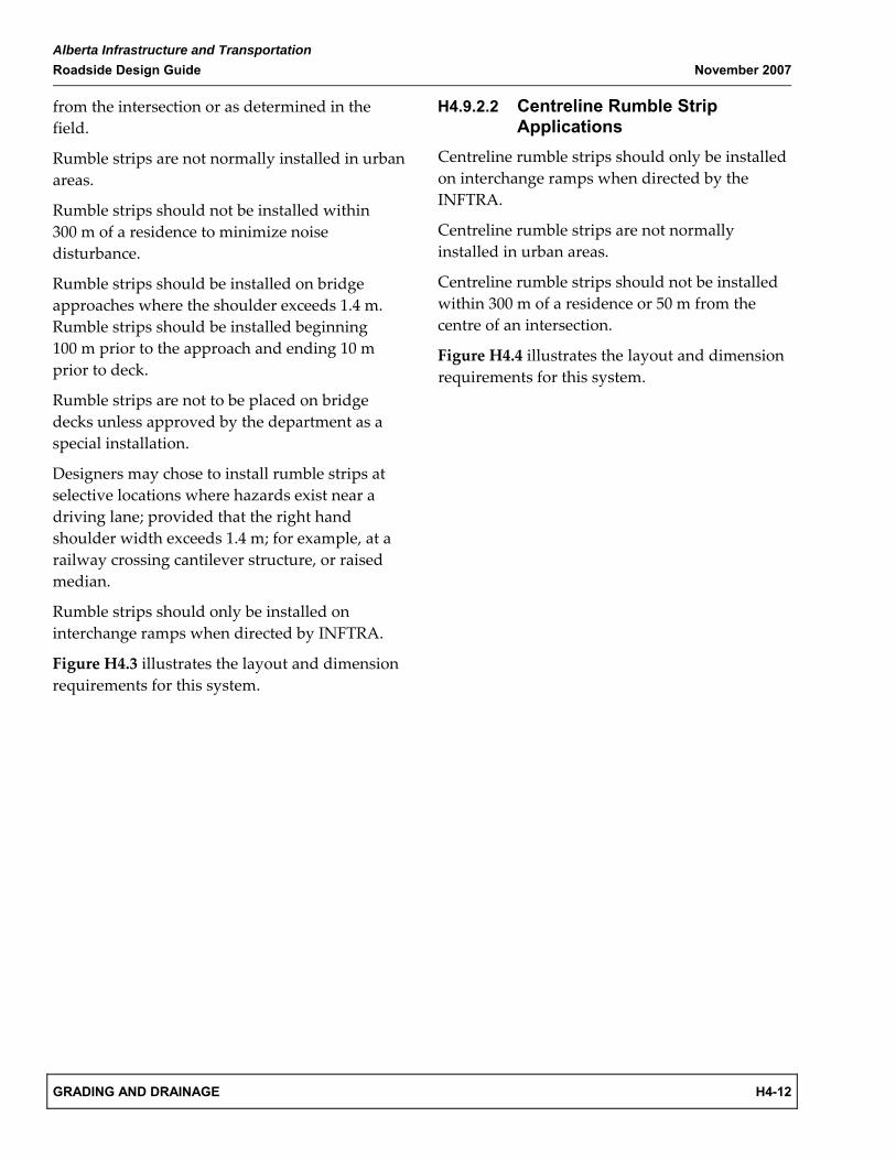
Milled rumble strips are installed with a milling machine or a bobcat equipped with a milling head. The maximum width of rumble strips is limited by the overall width of the milling head. However, the width may be reduced by removing some milling teeth from the milling head. The length (in the direction of travel) and the depth are dependent of the radius and the downward travelling distance of the milling head.
In February 1999, the standard width of milled rumble strips was reduced from 500 mm to 300 mm to provide more shoulder space for cycling traffic, to minimize annoyance to drivers of vehicles partially encroaching on the shoulder to allow other vehicles to pass, and to reduce the noise generated as a result of the encroaching movements.
H4.9.2 Rumble Strip Applications
H4.9.2.1 Shoulder Rumble Strip Applications
Generally, rumble strips are recommended on shoulder widths equal to or greater than 1.4 m, and on the left shoulder of divided highways where the shoulder width is 0.6 m or more.
At intersections with adequate tapers, rumble strips should terminate then begin again 60 m from the taper.
At intersections where there is no taper, rumble strips should terminate then begin again 200 m
Alberta Infrastructure and Transportation Roadside Design Guide November 2007
GRADING AND DRAINAGE H4-12
from the intersection or as determined in the field.
Rumble strips are not normally installed in urban areas.
Rumble strips should not be installed within 300 m of a residence to minimize noise disturbance.
Rumble strips should be installed on bridge approaches where the shoulder exceeds 1.4 m. Rumble strips should be installed beginning 100 m prior to the approach and ending 10 m prior to deck.
Rumble strips are not to be placed on bridge decks unless approved by the department as a special installation.
Designers may chose to install rumble strips at selective locations where hazards exist near a driving lane; provided that the right hand shoulder width exceeds 1.4 m; for example, at a railway crossing cantilever structure, or raised median.
Rumble strips should only be installed on interchange ramps when directed by INFTRA.
Figure H4.3 illustrates the layout and dimension requirements for this system.
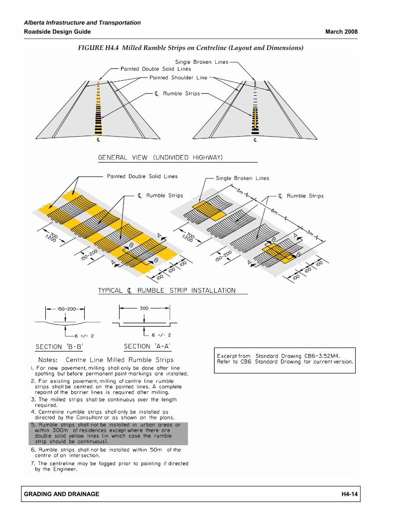
H4.9.2.2 Centreline Rumble Strip Applications
Centreline rumble strips should only be installed on interchange ramps when directed by the INFTRA.
Centreline rumble strips are not normally installed in urban areas.
Centreline rumble strips should not be installed within 300 m of a residence or 50 m from the centre of an intersection.
Figure H4.4 illustrates the layout and dimension requirements for this system.
Alberta Infrastructure and Transportation Roadside Design Guide March 2008
GRADING AND DRAINAGE H4-13
FIGURE H4.3 Milled Rumble Strips on Shoulders (Layout and Dimensions)
Alberta Infrastructure and Transportation Roadside Design Guide March 2008
GRADING AND DRAINAGE H4-14
FIGURE H4.4 Milled Rumble Strips on Centreline (Layout and Dimensions)

Alberta Infrastructure and Transportation Roadside Design Guide November 2007
GRADING AND DRAINAGE H4-15
H4.10 References The following documents were used during the development of this section:
Alberta Infrastructure and Transportation, Highway Geometric Design Guide, Edmonton, AB, 1999
Alberta Infrastructure and Transportation, Highway Geometric Design Guide – Urban Supplement (Draft), Edmonton, AB, 2003
Alberta Infrastructure and Transportation, Traffic Accommodation in Work Zones, Edmonton, AB, 2001
Alberta Infrastructure and Transportation, Traffic Accommodation in Work Zones – Urban Areas, Edmonton, AB, 2003
Alberta Infrastructure and Transportation, Traffic Control Standards Manual, Edmonton, AB, 1995
American Association of State Highway and Transportation Officials, Roadside Design Guide 2002, Washington, DC, 2002.
Canadian Highway Bridge Design Code (CSA‐S6‐06)
Joint Cooperative Committee of the American Association of State Highway and Transportation Officials, American Road and Transportation Builders Association, and Associated General Contractors of America, A Guide to Standardized Highway Barrier Hardware 1995

Alberta Infrastructure and Transportation Roadside Design Guide November 2007
GRADING AND DRAINAGE H4-16
THIS PAGE LEFT BLANK INTENTIONALLY