Embed Size (px)
Citation preview

Operating & Safety Manual
RL1000 & Charging Station
www.robomow.com / www.robomow.eu
DOC0100B
2
EC Declaration of Conformity
1. F. Robotics Acquisitions, Hatzabar St., Industrial Zone, Pardesiya, Israel declares that the
machines described in item 2 conforms with the directives listed in items 3 & 4.
2. Product: 24 Volt Battery operated automatic lawn mower, models RL350, RL500, RL550, RL800 RL850, RL1000*.
Serial number: see mark on the machine.
3. Tested by the British Standards Institute (BSI) to comply with The supply of Machine (Safety)
Regulation 1992 Essential Health and Safety Requirements relating to the design and construction
of machinery.
The following European standards were taken into consideration when testing the machine: EN 292: Parts 1 and 2:1991, Safety of Machinery - Basic concepts, general principles for design. EN 294: 1992, Safety of Machinery - Safety distances to prevent danger zones being reached by the upper limbs. EN 418:1992, Safety of Machinery - Emergency stop equipment, functional aspects - Principles for design. EN 60204: Part 1:1997, Safety of Machinery - Electrical equipment of machines - general requirements. EN 60335: Part 1:1994, Safety of household and similar electrical appliances. In addition the following National standard and draft were taken into consideration when testing the machine: BS 3456: Part 2: Section 2.42: 1997, Safety of household and similar electrical appliances - Section 2.42 Battery-operated lawnmowers. PrEN 50338: 1999, Safety of household and similar electrical appliances –Particular requirements for pedestrian controlled battery powered electrical lawnmowers. Noise level testing was conducted to the requirements of: 79/113/EEC and 88/181/EEC (also compliant with Directives 2000/14/EC and 98/37/EC).
Results are published by BSI in report number 282/4077203 dated 14 July 2000.
Marylands Avenue, Hemel Hempstead, Hertfordshire HP2 4SQ, UK.
4. Also tested by Hermon Laboratories to comply with The Electromagnetic compatibility directive
89/336/EEC. Results are published By Hermon Laboratories in report number Frienmc_EN.14123 dated 21 June 2000.
Rakevet Industry Zone, Binyamina, 30550, Israel.
5. Measured sound power level: 85 db.
6. Guaranteed sound power level: 90 db.
7. Technical documentation kept by Mr. Dedy Gur, QA director.
I hereby declare that the above product conforms to the requirements as specified above. *The original RL500 was tested by BSI in 2000. All Friendly Robotics models currently sold were tested by F.Robotics Acquisitions Ltd.
Issued at Shai Abramson – Senior VP R&D Pardesiya, Israel

3
The products are manufactured by F. Robotics Acquisitions (Friendly Robotics). CE approved. © Friendly Robotics, 2008-A. All rights reserved. No part of this document may be photocopied, reproduced, electronically or translated without the prior written consent of Friendly Robotics. Product, product specifications and this document are subject to change without notice. All other trademarks are property of their respective owners. Welcome to the world of home robotics with the Friendly Robotics Robomow! Thank you for purchasing our product. We know that you will enjoy the extra free time you will have while using Robomow to mow your lawn. When set up and used properly, Robomow will operate safely on your lawn and provide you with a quality of cut matched by a few mowers of any kind. You will be impressed with your lawn’s appearance and best of all, Robomow did it for you.
IMPORTANT!
The following pages contain important safety and operating instructions. Please read and follow all instructions in this manual. Carefully read and
review all safety instructions, warnings and cautions contained in this manual. Failure to read and follow these instructions, warnings and cautionary statements
may result in severe injury or death to persons and pets or damage to personal property.
4
Table of Contents
Safety Warnings & Precautions ………………………………………….….……… 5
Safety Features …………………………………………………………….….…..…. 8
What’s in the Box ………………………………………………………………….... 10
Chapter 1 – Charging Station & Perimeter Wire Setup…………………..….….. 12
Chapter 2 – Preparing the Robomow® ……………………………………………. 30
Chapter 3 – Manual & Automatic Operation…………………………………….…38
Chapter 4 – Setting the Weekly Program…………………………………………..44
Chapter 5 – Charging…………………………………………………………………48
Chapter 6 – Settings and Advanced Features……………………………….….…52
Chapter 7 – Text Messages and Troubleshooting……………………………..….60
Chapter 8 – Specifications……………………………………….…………………..67
Chapter 9 – Maintenance and Storage…………………………………………..…68
Chapter 10 – Accessories……………………………………………………….…...72
Tips for maintaining your lawn………………………………………………………..73 Limited warranty………………………………………………………………………..74
5
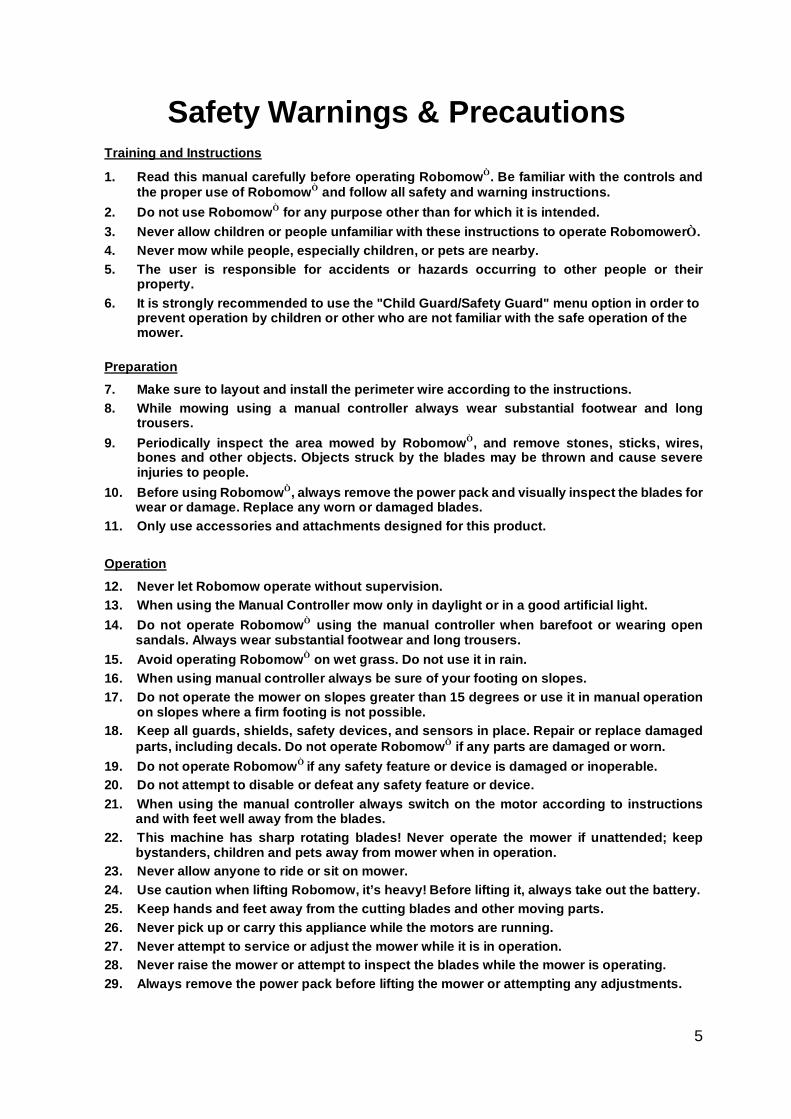
Safety Warnings & Precautions
Training and Instructions
1. Read this manual carefully before operating Robomow. Be familiar with the controls and the proper use of Robomow and follow all safety and warning instructions.
2. Do not use Robomow for any purpose other than for which it is intended. 3. Never allow children or people unfamiliar with these instructions to operate Robomower. 4. Never mow while people, especially children, or pets are nearby. 5. The user is responsible for accidents or hazards occurring to other people or their
property. 6. It is strongly recommended to use the "Child Guard/Safety Guard" menu option in order to
prevent operation by children or other who are not familiar with the safe operation of the mower.
Preparation 7. Make sure to layout and install the perimeter wire according to the instructions. 8. While mowing using a manual controller always wear substantial footwear and long
trousers. 9. Periodically inspect the area mowed by Robomow, and remove stones, sticks, wires,
bones and other objects. Objects struck by the blades may be thrown and cause severe injuries to people.
10. Before using Robomow, always remove the power pack and visually inspect the blades for wear or damage. Replace any worn or damaged blades.
11. Only use accessories and attachments designed for this product.
Operation 12. Never let Robomow operate without supervision. 13. When using the Manual Controller mow only in daylight or in a good artificial light. 14. Do not operate Robomow using the manual controller when barefoot or wearing open
sandals. Always wear substantial footwear and long trousers. 15. Avoid operating Robomow on wet grass. Do not use it in rain. 16. When using manual controller always be sure of your footing on slopes. 17. Do not operate the mower on slopes greater than 15 degrees or use it in manual operation
on slopes where a firm footing is not possible. 18. Keep all guards, shields, safety devices, and sensors in place. Repair or replace damaged
parts, including decals. Do not operate Robomow if any parts are damaged or worn. 19. Do not operate Robomow if any safety feature or device is damaged or inoperable. 20. Do not attempt to disable or defeat any safety feature or device. 21. When using the manual controller always switch on the motor according to instructions
and with feet well away from the blades. 22. This machine has sharp rotating blades! Never operate the mower if unattended; keep
bystanders, children and pets away from mower when in operation. 23. Never allow anyone to ride or sit on mower. 24. Use caution when lifting Robomow, it’s heavy! Before lifting it, always take out the battery. 25. Keep hands and feet away from the cutting blades and other moving parts. 26. Never pick up or carry this appliance while the motors are running. 27. Never attempt to service or adjust the mower while it is in operation. 28. Never raise the mower or attempt to inspect the blades while the mower is operating. 29. Always remove the power pack before lifting the mower or attempting any adjustments.
6
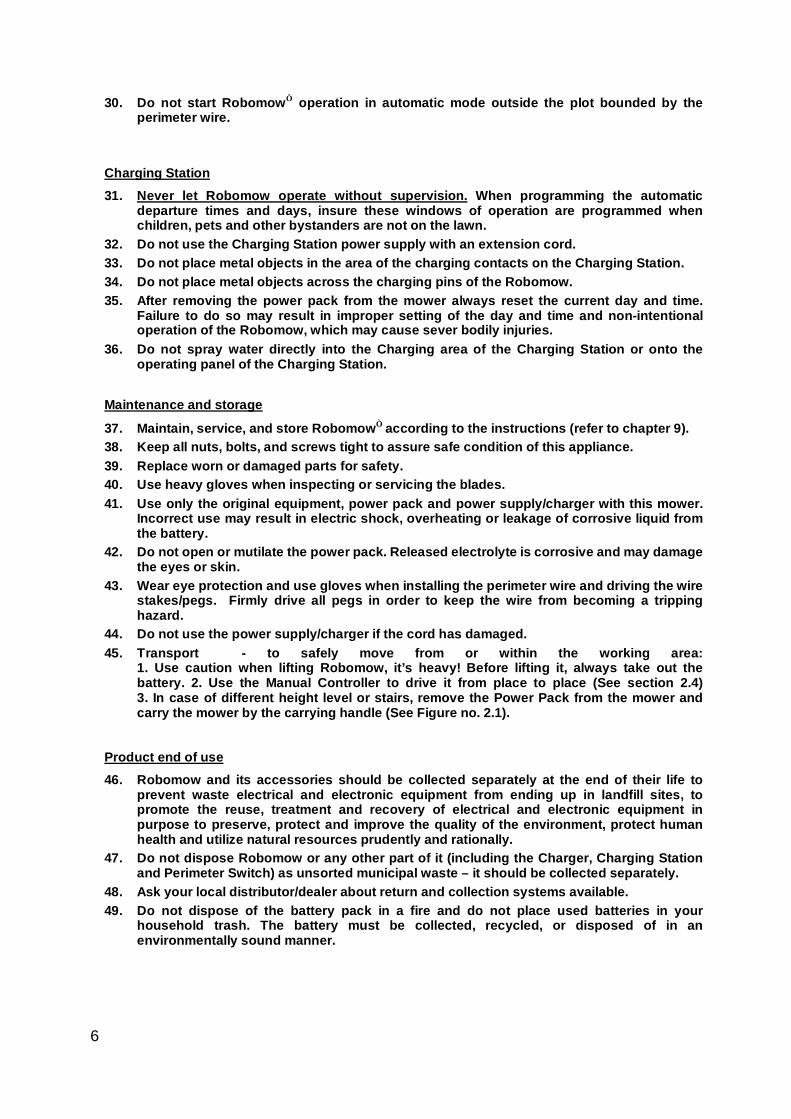
30. Do not start Robomow operation in automatic mode outside the plot bounded by the perimeter wire.
Charging Station 31. Never let Robomow operate without supervision. When programming the automatic
departure times and days, insure these windows of operation are programmed when children, pets and other bystanders are not on the lawn.
32. Do not use the Charging Station power supply with an extension cord. 33. Do not place metal objects in the area of the charging contacts on the Charging Station. 34. Do not place metal objects across the charging pins of the Robomow. 35. After removing the power pack from the mower always reset the current day and time.
Failure to do so may result in improper setting of the day and time and non-intentional operation of the Robomow, which may cause sever bodily injuries.
36. Do not spray water directly into the Charging area of the Charging Station or onto the operating panel of the Charging Station.
Maintenance and storage
37. Maintain, service, and store Robomow according to the instructions (refer to chapter 9). 38. Keep all nuts, bolts, and screws tight to assure safe condition of this appliance. 39. Replace worn or damaged parts for safety. 40. Use heavy gloves when inspecting or servicing the blades. 41. Use only the original equipment, power pack and power supply/charger with this mower.
Incorrect use may result in electric shock, overheating or leakage of corrosive liquid from the battery.
42. Do not open or mutilate the power pack. Released electrolyte is corrosive and may damage the eyes or skin.
43. Wear eye protection and use gloves when installing the perimeter wire and driving the wire stakes/pegs. Firmly drive all pegs in order to keep the wire from becoming a tripping hazard.
44. Do not use the power supply/charger if the cord has damaged. 45. Transport - to safely move from or within the working area:
1. Use caution when lifting Robomow, it’s heavy! Before lifting it, always take out the battery. 2. Use the Manual Controller to drive it from place to place (See section 2.4) 3. In case of different height level or stairs, remove the Power Pack from the mower and carry the mower by the carrying handle (See Figure no. 2.1).
Product end of use 46. Robomow and its accessories should be collected separately at the end of their life to
prevent waste electrical and electronic equipment from ending up in landfill sites, to promote the reuse, treatment and recovery of electrical and electronic equipment in purpose to preserve, protect and improve the quality of the environment, protect human health and utilize natural resources prudently and rationally.
47. Do not dispose Robomow or any other part of it (including the Charger, Charging Station and Perimeter Switch) as unsorted municipal waste – it should be collected separately.
48. Ask your local distributor/dealer about return and collection systems available. 49. Do not dispose of the battery pack in a fire and do not place used batteries in your
household trash. The battery must be collected, recycled, or disposed of in an environmentally sound manner.
7
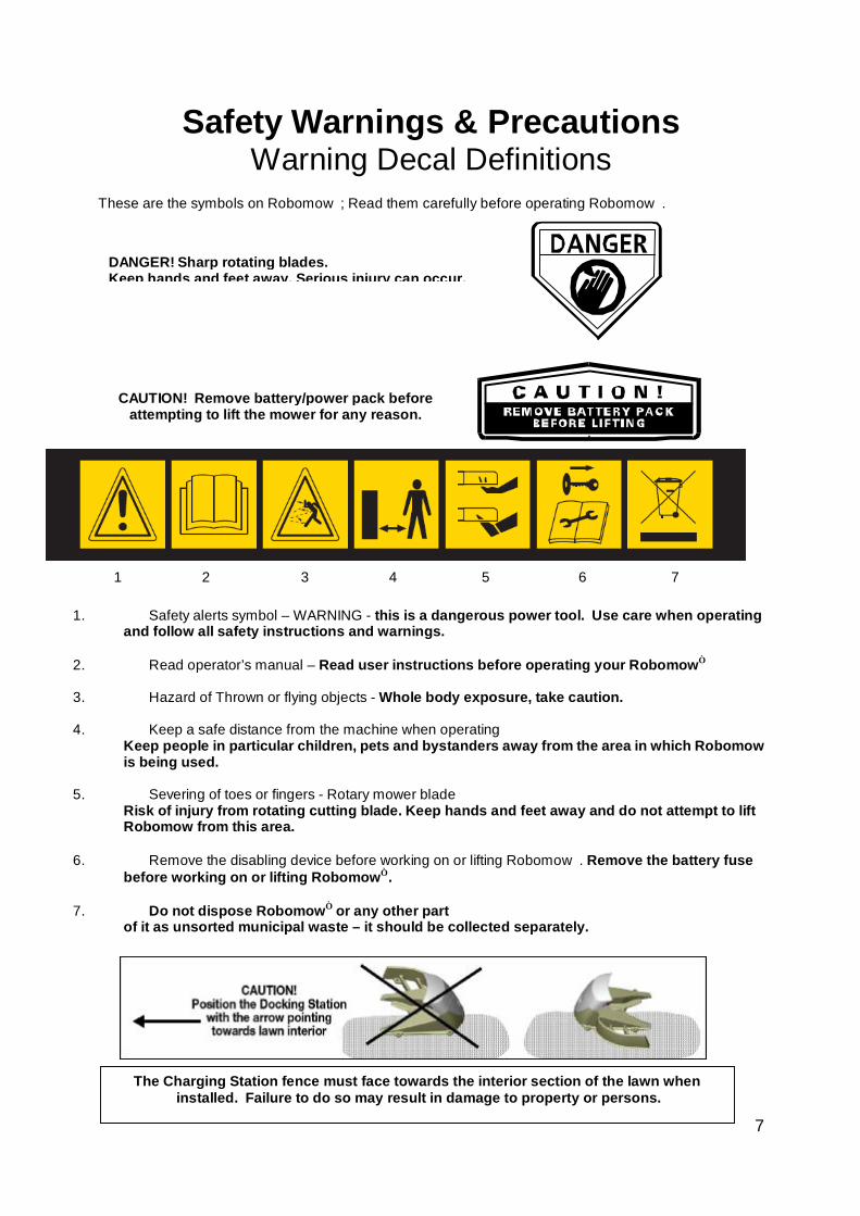
DANGER! Sharp rotating blades. Keep hands and feet away. Serious injury can occur.
CAUTION! Remove battery/power pack before attempting to lift the mower for any reason.
Safety Warnings & Precautions Warning Decal Definitions
These are the symbols on Robomow; Read them carefully before operating Robomow.
1. Safety alerts symbol – WARNING - this is a dangerous power tool. Use care when operating and follow all safety instructions and warnings.
2. Read operator’s manual – Read user instructions before operating your Robomow
3. Hazard of Thrown or flying objects - Whole body exposure, take caution.
4. Keep a safe distance from the machine when operating Keep people in particular children, pets and bystanders away from the area in which Robomow is being used.
5. Severing of toes or fingers - Rotary mower blade Risk of injury from rotating cutting blade. Keep hands and feet away and do not attempt to lift Robomow from this area.
6. Remove the disabling device before working on or lifting Robomow. Remove the battery fuse before working on or lifting Robomow.
7. Do not dispose Robomow or any other part of it as unsorted municipal waste – it should be collected separately.
The Charging Station fence must face towards the interior section of the lawn when
installed. Failure to do so may result in damage to property or persons.
1 2 3 4 5 6 7

8
Robomow® - Safety Features
1. Child Guard / Safety Guard
This menu option offers a safety feature to help prevent children or others not familiar with the safe operation of the mower to operate it freely.
2. Lift Sensor
There is a sensor located on the front caster wheel of the mower. In the event the front of the mower is raised approximately 1-inch from its resting position on the ground during blade operation, the blades will stop rotating immediately (< 1 second).
3. Sensor Equipped Bumpers
The front and rear bumpers are equipped with contacts that will activate when the mower strikes a solid, fixed object when that object is at least 6-inches in vertical height from the supporting surface of the mower. When the bumper sensor is activated, the mower will stop movement in that direction and reverse itself away from the obstacle. In manual blade operation, bumper activation will stop the rotation of the blades immediately (<1 second).
4. Emergency Stop Switch
Located on the top outer surface of the manual controller, red in color. Pressing this button at any time during operation will stop all mower movement and stop the rotation of the blades immediately (<1 second).
5. Automatic Mode Recognition
The Robomow is designed so that it cannot be operated in the manual mode while the Manual Controller is in its pocket and it cannot operate in the automatic mode while the Manual Controller is removed.
6. Two-Step Operator Presence Control
While in manual mode, it requires two independent finger actions in order to engage the mower blades. Once engaged, the mower blade button must remain depressed to continue blade operation. Once released, the two-step engagement process must be repeated.
7. Electronically Controlled Charging System
The Robomow is equipped with an on-board charge control system. This allows you to keep the charger connected at all times, even after the battery is fully charged. The control system will prevent an overcharge to the battery and keep it fully charged and maintained for the next use.
8. Sealed Power Pack
The power pack that operates the Robomow is completely sealed and will not leak any type of fluids, regardless of position. In addition, the power pack contains a one-time-use fuse in the event of a short-circuit or power malfunction.
9. Perimeter Switch and Perimeter Wire
The Robomow cannot operate without a perimeter wire installed and activated through the Perimeter Switch. In the event the Perimeter Switch is turned off or otherwise fails to function, the Robomow will stop operating. Likewise, should a break in the perimeter wire occur the Robomow would again stop operation. A break in the perimeter wire prior to operation will prevent the Robomow from operating. The Robomow can only operate within the boundary of the perimeter wire.
10. Auto-Off Perimeter Switch
The auto-off feature of the perimeter switch shuts down the perimeter switch operation after approximately 5 hours of continuous operation. This is typically 2 to 3 hours after which a fully charged Power Pack will need to be re-charged. This helps to prevent unauthorized persons from attempting to re-start the Robomow after it has completed its operation.
9
11. Over-Current Monitoring Protection
Each of the three blade motors and each of the two wheel drive motors are monitored continuously during operation for any situation that may cause these motors to over-heat. In such event, the Robomow will stop operation of at least that motor and possibly the mower itself and indicate that the motor is cooling down. While unusual, this may happen when the mower is put in grass that is severely overgrown; the underside of the mower is clogged from poor cleaning maintenance; the mower has encountered an obstacle that is unable to activate the bumper sensor preventing it from moving; or a problem landscape area has caused the mower to get stuck and is preventing it from moving.
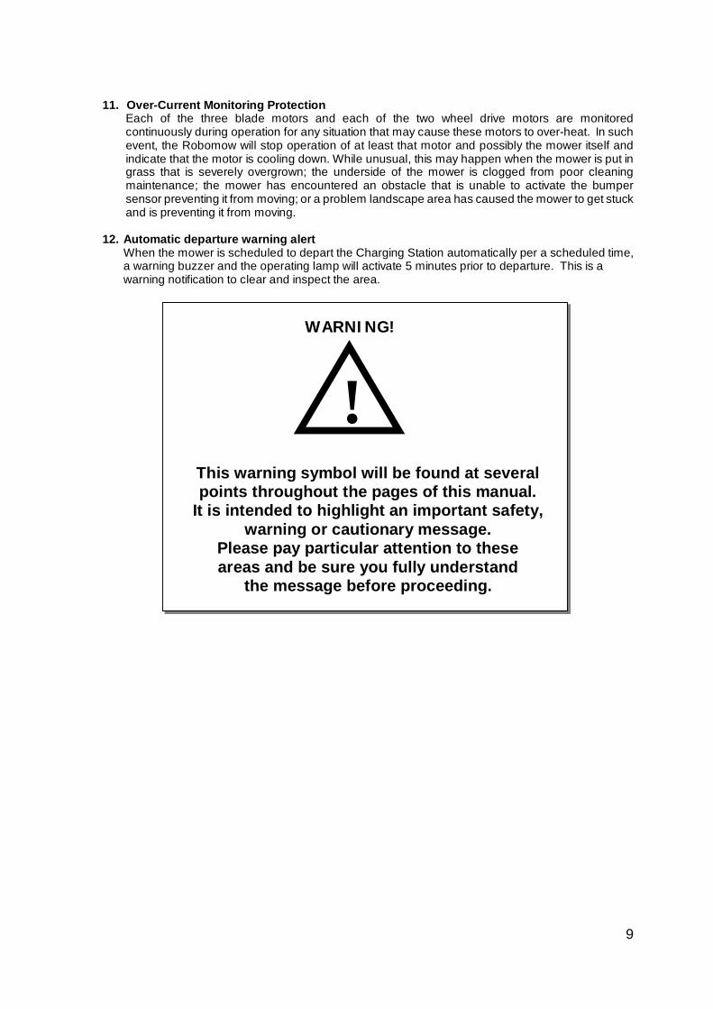
12. Automatic departure warning alert
When the mower is scheduled to depart the Charging Station automatically per a scheduled time, a warning buzzer and the operating lamp will activate 5 minutes prior to departure. This is a warning notification to clear and inspect the area.
This warning symbol will be found at several points throughout the pages of this manual.
It is intended to highlight an important safety, warning or cautionary message.
Please pay particular attention to these areas and be sure you fully understand
the message before proceeding.
WARNING!
!
10
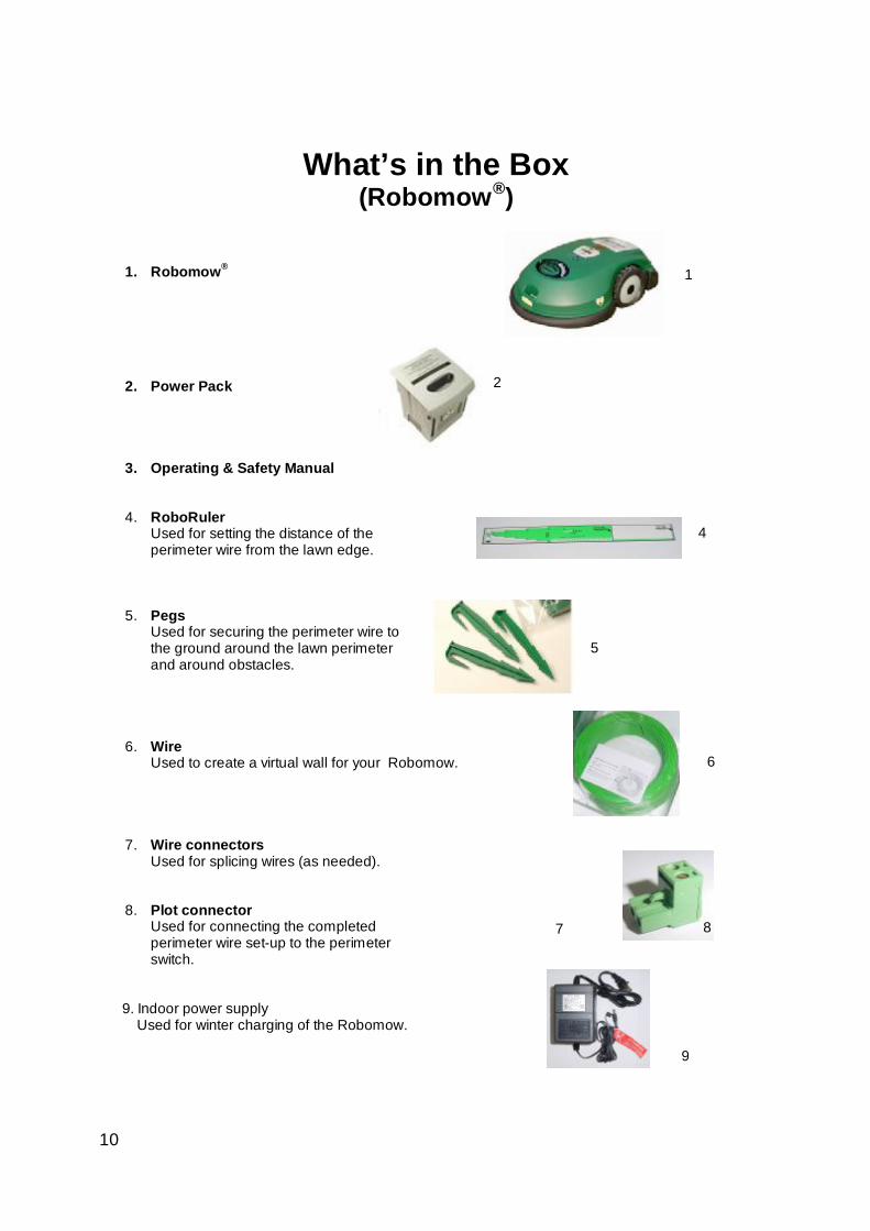
What’s in the Box (Robomow®)
1. Robomow®
2. Power Pack
3. Operating & Safety Manual
4. RoboRuler Used for setting the distance of the perimeter wire from the lawn edge.
5. Pegs Used for securing the perimeter wire to the ground around the lawn perimeter and around obstacles.
6. Wire Used to create a virtual wall for your Robomow.
7. Wire connectors Used for splicing wires (as needed).
8. Plot connector
Used for connecting the completed perimeter wire set-up to the perimeter switch.
9. Indoor power supply Used for winter charging of the Robomow.
6
2
4
7 8
5
1
9
11
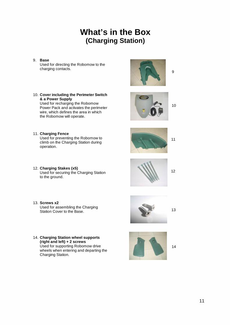
What’s in the Box (Charging Station)
9. Base Used for directing the Robomow to the charging contacts.
10. Cover including the Perimeter Switch & a Power Supply Used for recharging the Robomow Power Pack and activates the perimeter wire, which defines the area in which the Robomow will operate.
11. Charging Fence Used for preventing the Robomow to climb on the Charging Station during operation.
12. Charging Stakes (x5) Used for securing the Charging Station to the ground.
13. Screws x2 Used for assembling the Charging Station Cover to the Base.
14. Charging Station wheel supports (right and left) + 2 screws Used for supporting Robomow drive wheels when entering and departing the Charging Station.
9
12
10
11
1374
1474
12
The Fence should be inside lawn
40 Volts
Maximum 50 ft (15m)
Power Supply
Receptacle
120 V230 VThe Fence
should be inside lawn
40 Volts
Maximum 50 ft (15m)
Power Supply
Receptacle
120 V230 V
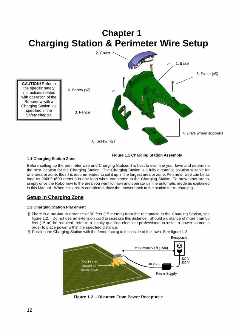
Chapter 1 Charging Station & Perimeter Wire Setup
1.1 Charging Station Zone Before setting up the perimeter wire and Charging Station, it is best to examine your lawn and determine the best location for the Charging Station. The Charging Station is a fully automatic solution suitable for one area or zone, thus it is recommended to set it up in the largest area or zone. Perimeter wire can be as long as 2000ft (600 meters) in one loop when connected to the Charging Station. To mow other areas, simply drive the Robomow to the area you want to mow and operate it in the automatic mode as explained in this Manual. When this area is completed, drive the mower back to the station for re-charging. Setup in Charging Zone
1.2 Charging Station Placement § There is a maximum distance of 50 feet (15 meters) from the receptacle to the Charging Station, see
figure 1.2. Do not use an extension cord to increase this distance. Should a distance of more than 50 feet (15 m) be required, refer to a locally qualified electrical professional to install a power source in order to place power within the specified distance.
§ Position the Charging Station with the fence facing to the inside of the lawn. See figure 1.2.
Figure 1.2 – Distance From Power Receptacle
2. Cover
1. Base
5. Stake (x5)
4. Drive wheel supports
3. Fence
6. Screw (x2)
6. Screw (x2)
Figure 1.1 Charging Station Assembly
CAUTION! Refer to the specific safety instructions related
with operation of the Robomow with a
Charging Station, as specified in the Safety chapter.
13
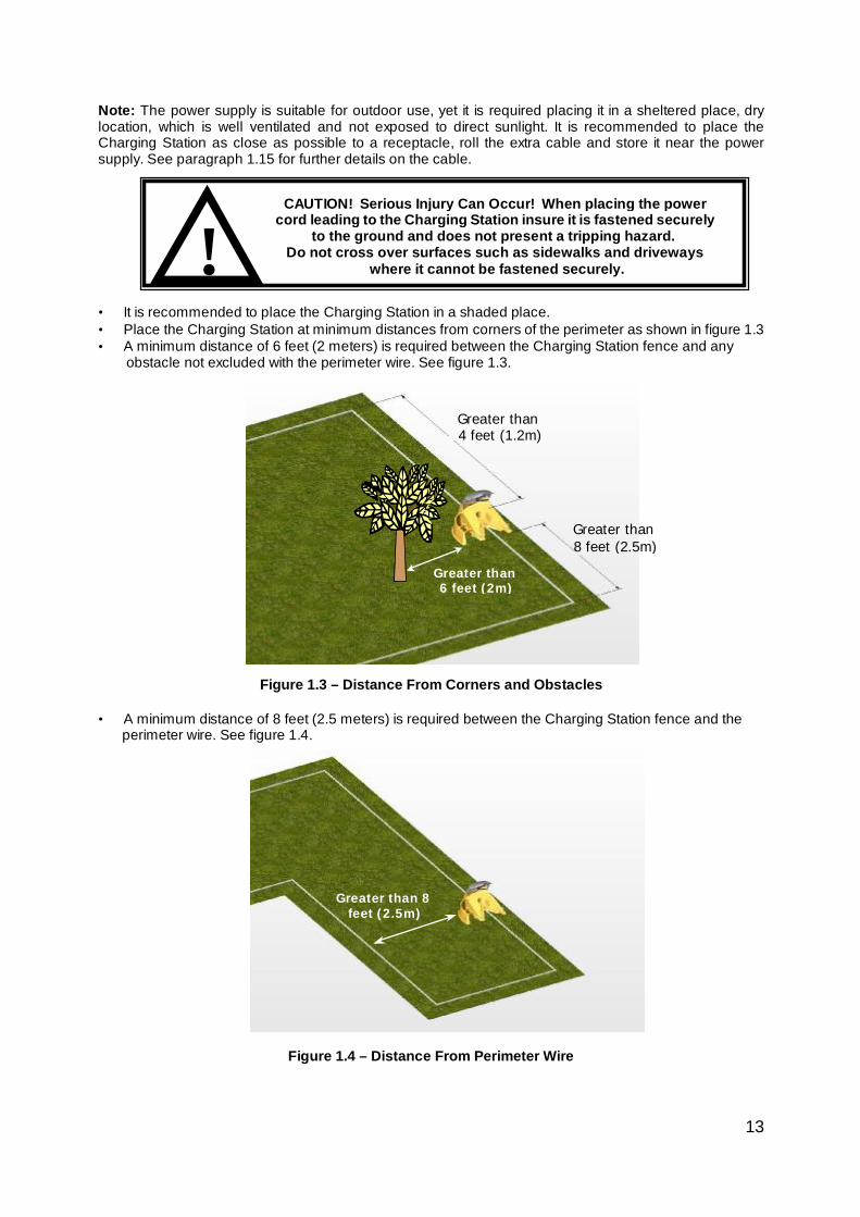
Note: The power supply is suitable for outdoor use, yet it is required placing it in a sheltered place, dry location, which is well ventilated and not exposed to direct sunlight. It is recommended to place the Charging Station as close as possible to a receptacle, roll the extra cable and store it near the power supply. See paragraph 1.15 for further details on the cable. • It is recommended to place the Charging Station in a shaded place. • Place the Charging Station at minimum distances from corners of the perimeter as shown in figure 1.3 • A minimum distance of 6 feet (2 meters) is required between the Charging Station fence and any
obstacle not excluded with the perimeter wire. See figure 1.3.
Figure 1.3 – Distance From Corners and Obstacles • A minimum distance of 8 feet (2.5 meters) is required between the Charging Station fence and the
perimeter wire. See figure 1.4.
Figure 1.4 – Distance From Perimeter Wire
CAUTION! Serious Injury Can Occur! When placing the power cord leading to the Charging Station insure it is fastened securely
to the ground and does not present a tripping hazard. Do not cross over surfaces such as sidewalks and driveways
where it cannot be fastened securely. !
Greater than 4 feet (1.2m)
Greater than 8 feet (2.5m)
Greater than 6 feet (2m)
Greater than 8 feet (2.5m)
14
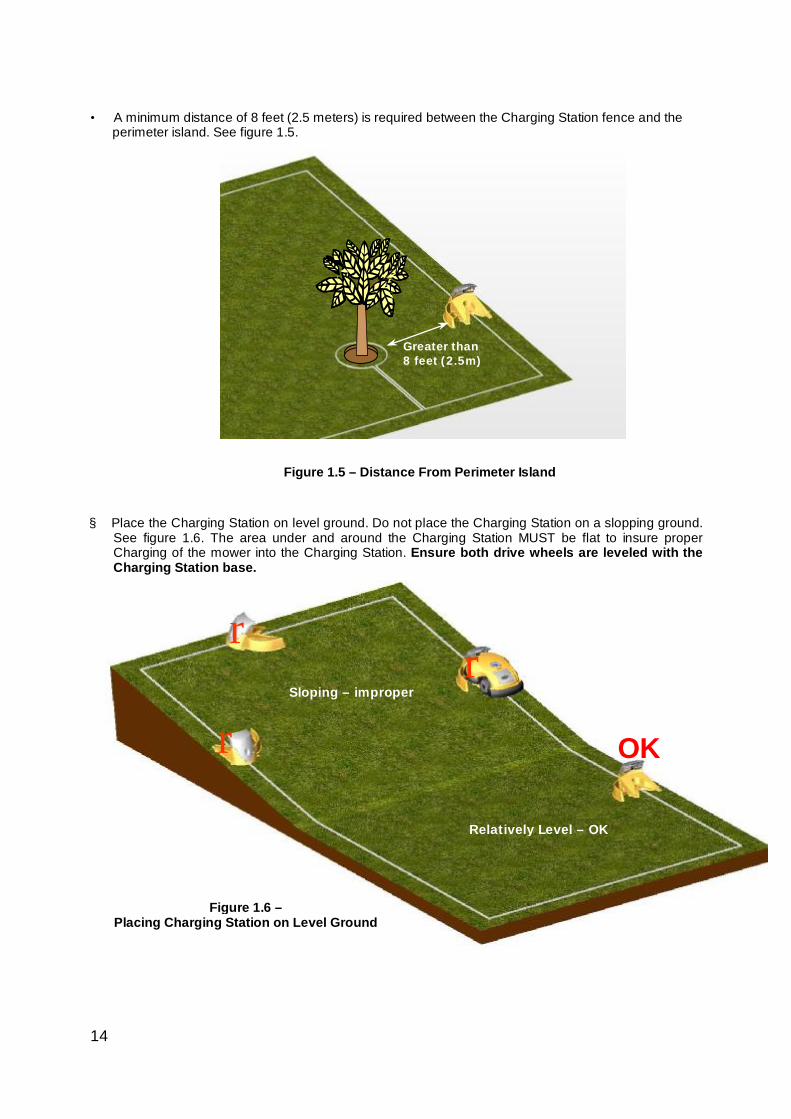
Greater than 8 feet (2.5m)
• A minimum distance of 8 feet (2.5 meters) is required between the Charging Station fence and the
perimeter island. See figure 1.5.
Figure 1.5 – Distance From Perimeter Island
§ Place the Charging Station on level ground. Do not place the Charging Station on a slopping ground.
See figure 1.6. The area under and around the Charging Station MUST be flat to insure proper Charging of the mower into the Charging Station. Ensure both drive wheels are leveled with the Charging Station base.
r
OK
r
r
Relatively Level – OK
Sloping – improper
Figure 1.6 – Placing Charging Station on Level Ground
15
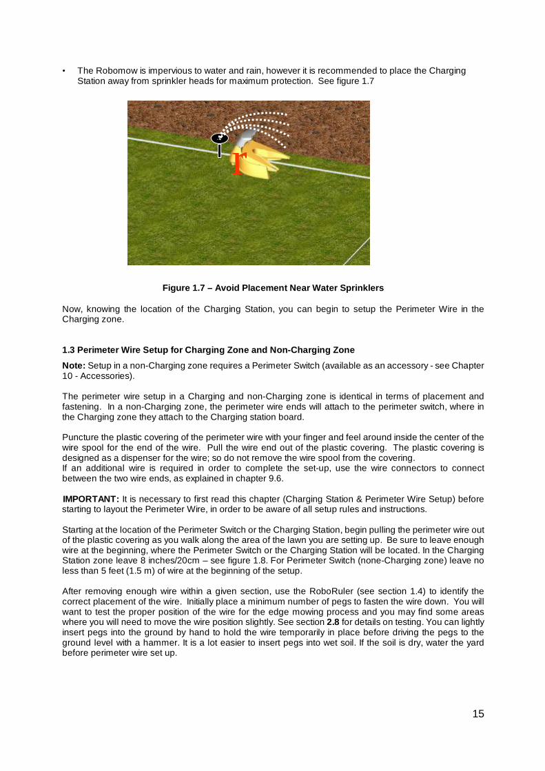
• The Robomow is impervious to water and rain, however it is recommended to place the Charging Station away from sprinkler heads for maximum protection. See figure 1.7
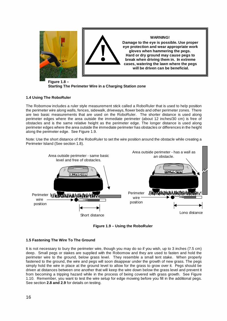
Figure 1.7 – Avoid Placement Near Water Sprinklers Now, knowing the location of the Charging Station, you can begin to setup the Perimeter Wire in the Charging zone. 1.3 Perimeter Wire Setup for Charging Zone and Non-Charging Zone Note: Setup in a non-Charging zone requires a Perimeter Switch (available as an accessory - see Chapter 10 - Accessories). The perimeter wire setup in a Charging and non-Charging zone is identical in terms of placement and fastening. In a non-Charging zone, the perimeter wire ends will attach to the perimeter switch, where in the Charging zone they attach to the Charging station board. Puncture the plastic covering of the perimeter wire with your finger and feel around inside the center of the wire spool for the end of the wire. Pull the wire end out of the plastic covering. The plastic covering is designed as a dispenser for the wire; so do not remove the wire spool from the covering. If an additional wire is required in order to complete the set-up, use the wire connectors to connect between the two wire ends, as explained in chapter 9.6. IMPORTANT: It is necessary to first read this chapter (Charging Station & Perimeter Wire Setup) before starting to layout the Perimeter Wire, in order to be aware of all setup rules and instructions. Starting at the location of the Perimeter Switch or the Charging Station, begin pulling the perimeter wire out of the plastic covering as you walk along the area of the lawn you are setting up. Be sure to leave enough wire at the beginning, where the Perimeter Switch or the Charging Station will be located. In the Charging Station zone leave 8 inches/20cm – see figure 1.8. For Perimeter Switch (none-Charging zone) leave no less than 5 feet (1.5 m) of wire at the beginning of the setup. After removing enough wire within a given section, use the RoboRuler (see section 1.4) to identify the correct placement of the wire. Initially place a minimum number of pegs to fasten the wire down. You will want to test the proper position of the wire for the edge mowing process and you may find some areas where you will need to move the wire position slightly. See section 2.8 for details on testing. You can lightly insert pegs into the ground by hand to hold the wire temporarily in place before driving the pegs to the ground level with a hammer. It is a lot easier to insert pegs into wet soil. If the soil is dry, water the yard before perimeter wire set up.
r
16
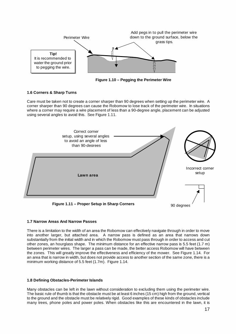
1.4 Using The RoboRuler The Robomow includes a ruler style measurement stick called a RoboRuler that is used to help position the perimeter wire along walls, fences, sidewalk, driveways, flower beds and other perimeter zones. There are two basic measurements that are used on the RoboRuler. The shorter distance is used along perimeter edges where the area outside the immediate perimeter (about 12 inches/30 cm) is free of obstacles and is the same relative height as the perimeter edge. The longer distance is used along perimeter edges where the area outside the immediate perimeter has obstacles or differences in the height along the perimeter edge. See Figure 1.9. Note: Use the short distance of the RoboRuler to set the wire position around the obstacle while creating a Perimeter Island (See section 1.8). 1.5 Fastening The Wire To The Ground It is not necessary to bury the perimeter wire, though you may do so if you wish, up to 3 inches (7.5 cm) deep. Small pegs or stakes are supplied with the Robomow and they are used to fasten and hold the perimeter wire to the ground, below grass level. They resemble a small tent stake. When properly fastened to the ground, the wire and pegs will soon disappear under the growth of new grass. The pegs simply hold the wire in place at the ground level to allow for the grass to grow over it. Pegs should be driven at distances between one another that will keep the wire down below the grass level and prevent it from becoming a tripping hazard while in the process of being covered with grass growth. See Figure 1.10. Remember, you want to test the wire setup for edge mowing before you fill in the additional pegs. See section 2.8 and 2.9 for details on testing.
Damage to the eye is possible. Use proper eye protection and wear appropriate work
gloves when hammering the pegs. Hard or dry ground may cause pegs to break when driving them in. In extreme
cases, watering the lawn where the pegs will be driven can be beneficial.
!WARNING!
Figure 1.8 – Starting The Perimeter Wire in a Charging Station zone
Short distance
Perimeter wire
position
Area outside perimeter - same basic level and free of obstacles.
Area outside perimeter - has a wall as an obstacle.
Long distance
Perimeter wire
position
Figure 1.9 – Using the RoboRuler
17
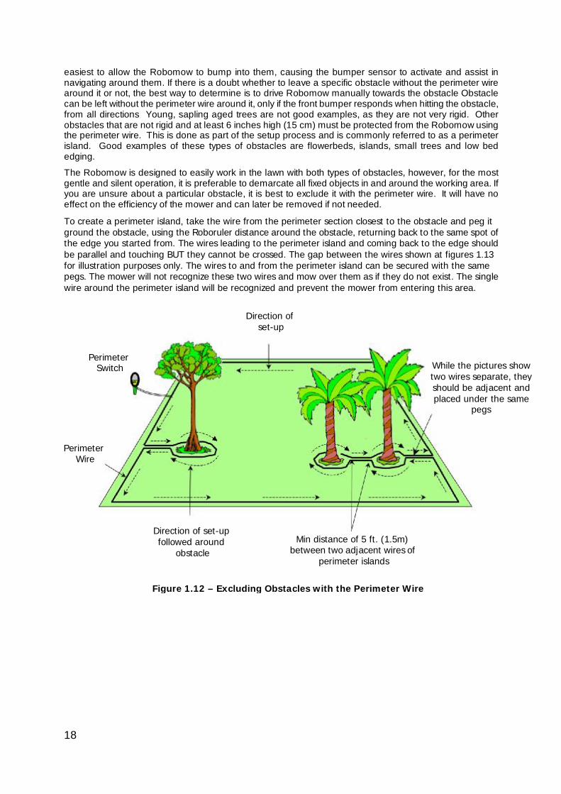
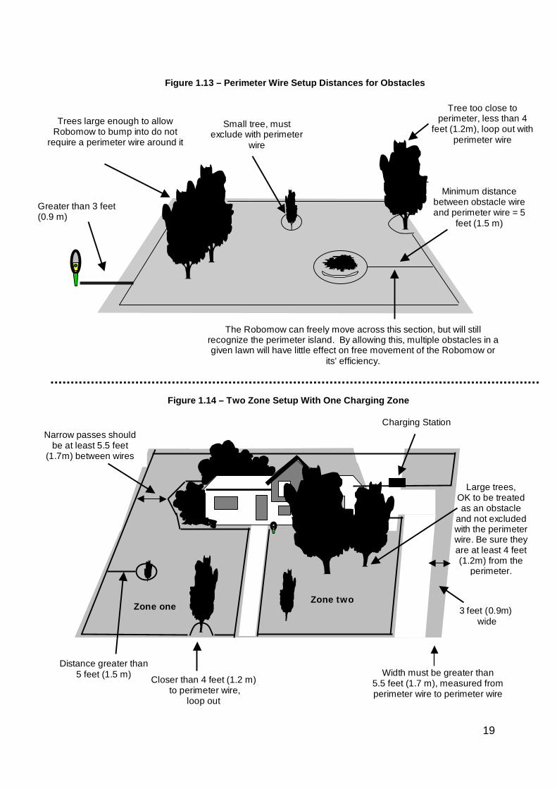
1.6 Corners & Sharp Turns Care must be taken not to create a corner sharper than 90 degrees when setting up the perimeter wire. A corner sharper than 90 degrees can cause the Robomow to lose track of the perimeter wire. In situations where a corner may require a wire placement of less than a 90-degree angle, placement can be adjusted using several angles to avoid this. See Figure 1.11. 1.7 Narrow Areas And Narrow Passes There is a limitation to the width of an area the Robomow can effectively navigate through in order to move into another larger, but attached area. A narrow pass is defined as an area that narrows down substantially from the initial width and in which the Robomow must pass through in order to access and cut other zones, an hourglass shape. The minimum distance for an effective narrow pass is 5.5 feet (1.7 m) between perimeter wires. The larger a pass can be made, the better access Robomow will have between the zones. This will greatly improve the effectiveness and efficiency of the mower. See Figure 1.14. For an area that is narrow in width, but does not provide access to another section of the same zone, there is a minimum working distance of 5.5 feet (1.7m). Figure 1.14. 1.8 Defining Obstacles-Perimeter Islands
Many obstacles can be left in the lawn without consideration to excluding them using the perimeter wire. The basic rule of thumb is that the obstacle must be at least 6 inches (15 cm) high from the ground, vertical to the ground and the obstacle must be relatively rigid. Good examples of these kinds of obstacles include many trees, phone poles and power poles. When obstacles like this are encountered in the lawn, it is
Correct corner setup, using several angles to avoid an angle of less
than 90-degrees
Incorrect corner
setup
Figure 1.11 – Proper Setup in Sharp Corners
Lawn area
90 degrees
Figure 1.10 – Pegging the Perimeter Wire
Perimeter Wire Add pegs in to pull the perimeter wire down to the ground surface, below the
grass tips.
Tip! It is recommended to water the ground prior
to pegging the wire.
18
easiest to allow the Robomow to bump into them, causing the bumper sensor to activate and assist in navigating around them. If there is a doubt whether to leave a specific obstacle without the perimeter wire around it or not, the best way to determine is to drive Robomow manually towards the obstacle Obstacle can be left without the perimeter wire around it, only if the front bumper responds when hitting the obstacle, from all directions Young, sapling aged trees are not good examples, as they are not very rigid. Other obstacles that are not rigid and at least 6 inches high (15 cm) must be protected from the Robomow using the perimeter wire. This is done as part of the setup process and is commonly referred to as a perimeter island. Good examples of these types of obstacles are flowerbeds, islands, small trees and low bed edging.
The Robomow is designed to easily work in the lawn with both types of obstacles, however, for the most gentle and silent operation, it is preferable to demarcate all fixed objects in and around the working area. If you are unsure about a particular obstacle, it is best to exclude it with the perimeter wire. It will have no effect on the efficiency of the mower and can later be removed if not needed.
To create a perimeter island, take the wire from the perimeter section closest to the obstacle and peg it ground the obstacle, using the Roboruler distance around the obstacle, returning back to the same spot of the edge you started from. The wires leading to the perimeter island and coming back to the edge should be parallel and touching BUT they cannot be crossed. The gap between the wires shown at figures 1.13 for illustration purposes only. The wires to and from the perimeter island can be secured with the same pegs. The mower will not recognize these two wires and mow over them as if they do not exist. The single wire around the perimeter island will be recognized and prevent the mower from entering this area.
Figure 1.12 – Excluding Obstacles with the Perimeter Wire
While the pictures show two wires separate, they should be adjacent and placed under the same
pegs
Direction of set-up
Perimeter Switch
Perimeter Wire
Min distance of 5 ft. (1.5m) between two adjacent wires of
perimeter islands
Direction of set-up followed around
obstacle
19
Large trees, OK to be treated as an obstacle
and not excluded with the perimeter wire. Be sure they are at least 4 feet (1.2m) from the
perimeter.
Zone one Zone two
Width must be greater than 5.5 feet (1.7 m), measured from perimeter wire to perimeter wire
3 feet (0.9m) wide
Distance greater than 5 feet (1.5 m)
Figure 1.14 – Two Zone Setup With One Charging Zone
Narrow passes should be at least 5.5 feet
(1.7m) between wires
Closer than 4 feet (1.2 m) to perimeter wire,
loop out
Charging Station
Trees large enough to allow Robomow to bump into do not
require a perimeter wire around it
Small tree, must exclude with perimeter
wire
Tree too close to perimeter, less than 4
feet (1.2m), loop out with perimeter wire
Minimum distance between obstacle wire and perimeter wire = 5
feet (1.5 m)
Greater than 3 feet (0.9 m)
The Robomow can freely move across this section, but will still recognize the perimeter island. By allowing this, multiple obstacles in a given lawn will have little effect on free movement of the Robomow or
its’ efficiency.
Figure 1.13 – Perimeter Wire Setup Distances for Obstacles
20
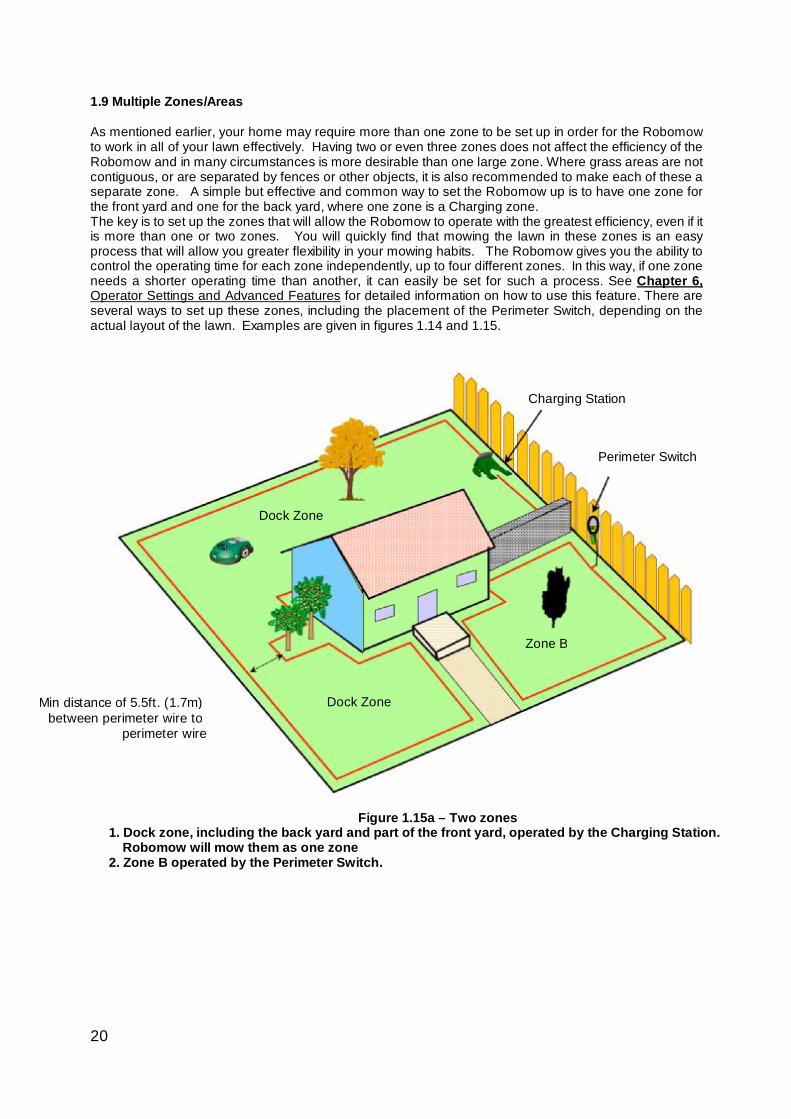
1.9 Multiple Zones/Areas As mentioned earlier, your home may require more than one zone to be set up in order for the Robomow to work in all of your lawn effectively. Having two or even three zones does not affect the efficiency of the Robomow and in many circumstances is more desirable than one large zone. Where grass areas are not contiguous, or are separated by fences or other objects, it is also recommended to make each of these a separate zone. A simple but effective and common way to set the Robomow up is to have one zone for the front yard and one for the back yard, where one zone is a Charging zone. The key is to set up the zones that will allow the Robomow to operate with the greatest efficiency, even if it is more than one or two zones. You will quickly find that mowing the lawn in these zones is an easy process that will allow you greater flexibility in your mowing habits. The Robomow gives you the ability to control the operating time for each zone independently, up to four different zones. In this way, if one zone needs a shorter operating time than another, it can easily be set for such a process. See Chapter 6, Operator Settings and Advanced Features for detailed information on how to use this feature. There are several ways to set up these zones, including the placement of the Perimeter Switch, depending on the actual layout of the lawn. Examples are given in figures 1.14 and 1.15.
Charging Station
Perimeter Switch
Zone B
Dock Zone
Dock Zone
Min distance of 5.5ft. (1.7m) between perimeter wire to
perimeter wire
Figure 1.15a – Two zones 1. Dock zone, including the back yard and part of the front yard, operated by the Charging Station. Robomow will mow them as one zone 2. Zone B operated by the Perimeter Switch.
21
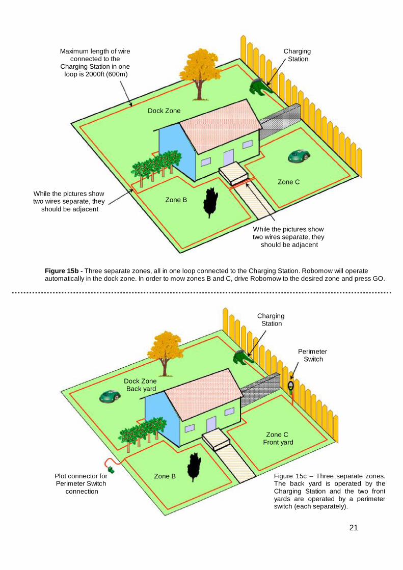
Maximum length of wire connected to the
Charging Station in one loop is 2000ft (600m)
Charging Station
While the pictures show two wires separate, they
should be adjacent
While the pictures show two wires separate, they
should be adjacent
Dock Zone
Zone B
Zone C
Figure 15b - Three separate zones, all in one loop connected to the Charging Station. Robomow will operate automatically in the dock zone. In order to mow zones B and C, drive Robomow to the desired zone and press GO.
Figure 15c – Three separate zones. The back yard is operated by the Charging Station and the two front yards are operated by a perimeter switch (each separately).
Charging Station
Perimeter Switch
Plot connector for Perimeter Switch
connection
Dock Zone Back yard
Zone B
Zone C Front yard
22
1.10 Slopes As a general rule of thumb, any slope that can safely be cut using a walk behind mower can also be cut using the Robomow in the automatic mode. The maximum slope limit is 15 degrees, the same as a traditional walk behind mower. Bear in mind that a 15-degree slope, though it may not sound very steep, is in fact a relatively steep slope. In cases where it is attempted to operate the Robomow on a slope that is too severe, normally the front of the machine will try to rise from the ground surface slightly when climbing the slope vertically. The lift sensor will then activate, shutting the blades down for safety. The mower will drop back into position and may attempt the maneuver again. In any event, a slope that causes the front of the mower to raise from the ground while climbing is too steep and should not be included as part of the cutting area. In some cases, this area can be cut manually with the Robomow, using the manual controller. Insure that you can maintain a sure and safe footing before attempting to cut a slope area in manual. If you are unsure as to whether a slope is too steep or not, attempt driving the Robomow manually up the slope. If the front of the mower does not lift from the ground, the slope is fine to include in the cutting area. If however it does lift, exclude this section from the cutting area.
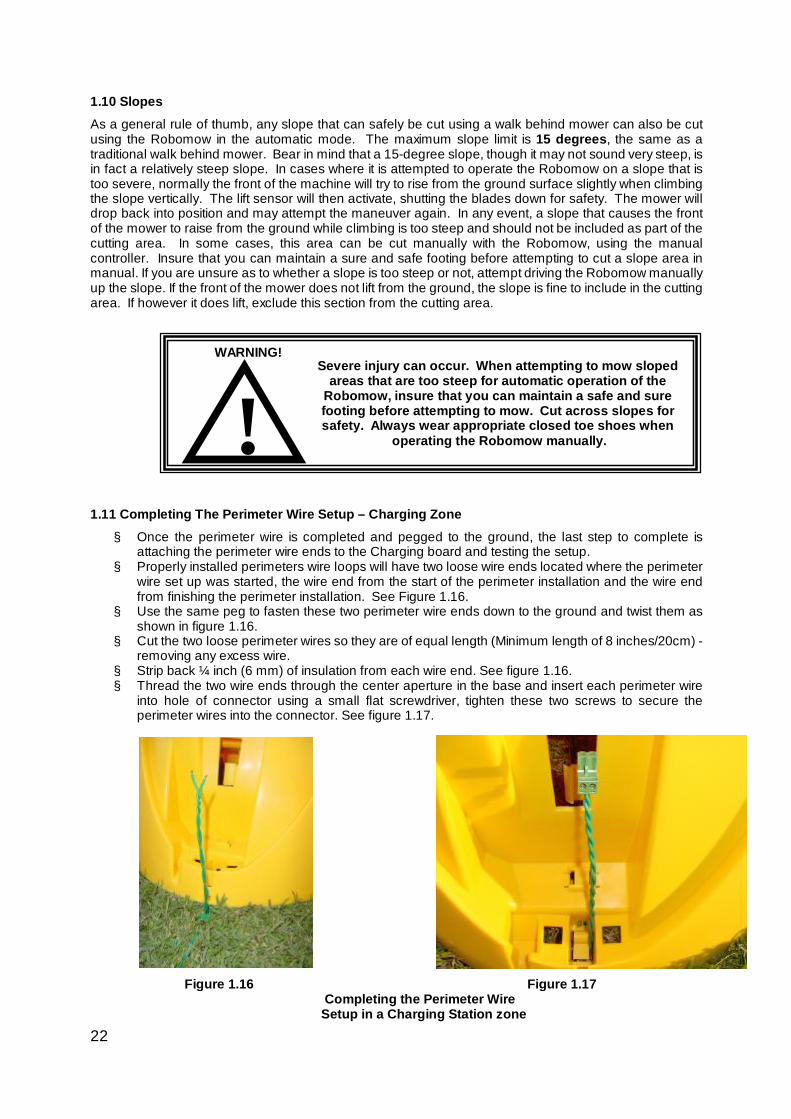
1.11 Completing The Perimeter Wire Setup – Charging Zone § Once the perimeter wire is completed and pegged to the ground, the last step to complete is
attaching the perimeter wire ends to the Charging board and testing the setup. § Properly installed perimeters wire loops will have two loose wire ends located where the perimeter
wire set up was started, the wire end from the start of the perimeter installation and the wire end from finishing the perimeter installation. See Figure 1.16.
§ Use the same peg to fasten these two perimeter wire ends down to the ground and twist them as shown in figure 1.16.
§ Cut the two loose perimeter wires so they are of equal length (Minimum length of 8 inches/20cm) - removing any excess wire.
§ Strip back ¼ inch (6 mm) of insulation from each wire end. See figure 1.16. § Thread the two wire ends through the center aperture in the base and insert each perimeter wire
into hole of connector using a small flat screwdriver, tighten these two screws to secure the perimeter wires into the connector. See figure 1.17.
Severe injury can occur. When attempting to mow sloped areas that are too steep for automatic operation of the
Robomow, insure that you can maintain a safe and sure footing before attempting to mow. Cut across slopes for safety. Always wear appropriate closed toe shoes when
operating the Robomow manually. !WARNING!
Figure 1.16 Figure 1.17 Completing the Perimeter Wire Setup in a Charging Station zone
23
1.12 Assemble Power Supply Cord to Charging Board § Before securing the power cord to the Charging Station, carefully lay the length of the cord out,
beginning from the Charging Station and leading to the main power supply to insure that the Charging Station is placed close enough to the main power for the supply cord to reach.
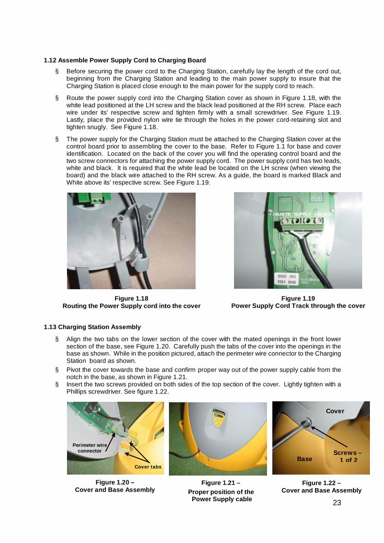
§ Route the power supply cord into the Charging Station cover as shown in Figure 1.18, with the white lead positioned at the LH screw and the black lead positioned at the RH screw. Place each wire under its’ respective screw and tighten firmly with a small screwdriver. See Figure 1.19. Lastly, place the provided nylon wire tie through the holes in the power cord-retaining slot and tighten snugly. See Figure 1.18.
§ The power supply for the Charging Station must be attached to the Charging Station cover at the control board prior to assembling the cover to the base. Refer to Figure 1.1 for base and cover identification. Located on the back of the cover you will find the operating control board and the two screw connectors for attaching the power supply cord. The power supply cord has two leads, white and black. It is required that the white lead be located on the LH screw (when viewing the board) and the black wire attached to the RH screw. As a guide, the board is marked Black and White above its’ respective screw. See Figure 1.19.
1.13 Charging Station Assembly
§ Align the two tabs on the lower section of the cover with the mated openings in the front lower section of the base, see Figure 1.20. Carefully push the tabs of the cover into the openings in the base as shown. While in the position pictured, attach the perimeter wire connector to the Charging Station board as shown.
§ Pivot the cover towards the base and confirm proper way out of the power supply cable from the notch in the base, as shown in Figure 1.21.
§ Insert the two screws provided on both sides of the top section of the cover. Lightly tighten with a Phillips screwdriver. See figure 1.22.
Figure 1.20 – Cover and Base Assembly
Figure 1.18 Routing the Power Supply cord into the cover
+/WHITE SUPPLY -/BLACK
Figure 1.19 Power Supply Cord Track through the cover
Cover tabs
Perimeter wire connector
Figure 1.21 – Proper position of the
Power Supply cable
Figure 1.22 – Cover and Base Assembly
Cover
Base Screws –
1 of 2
24
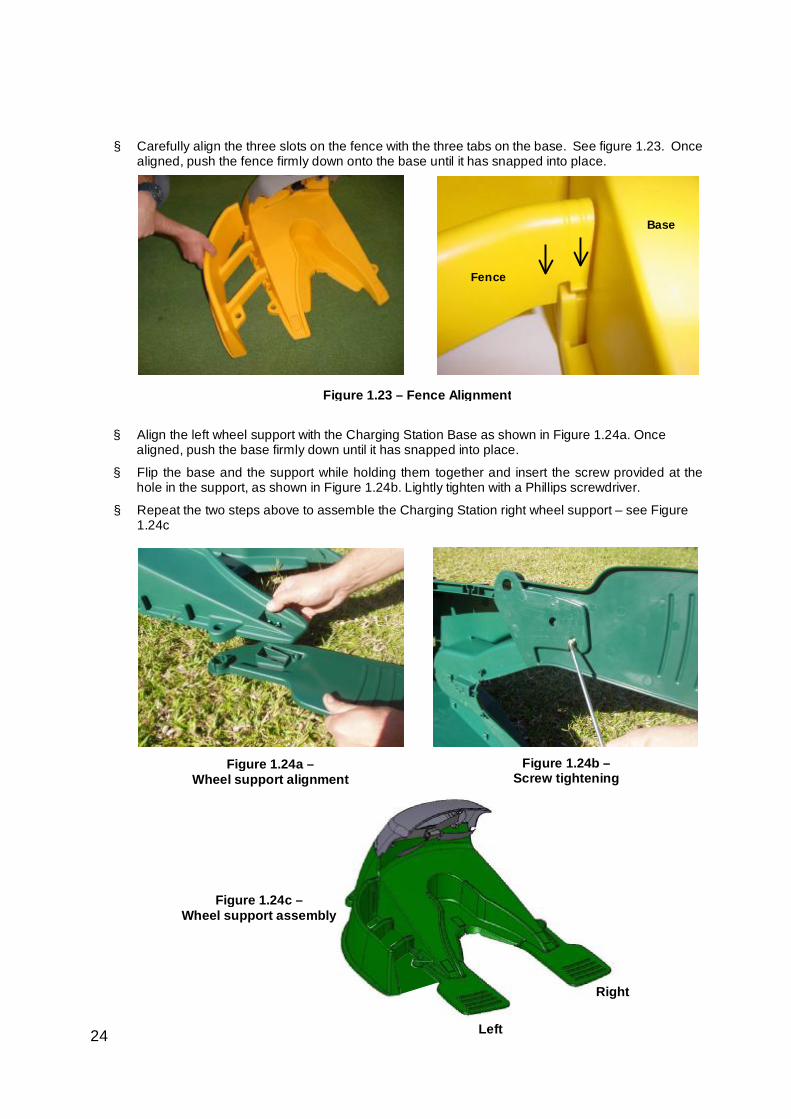
§ Carefully align the three slots on the fence with the three tabs on the base. See figure 1.23. Once aligned, push the fence firmly down onto the base until it has snapped into place.
§ Align the left wheel support with the Charging Station Base as shown in Figure 1.24a. Once
aligned, push the base firmly down until it has snapped into place.
§ Flip the base and the support while holding them together and insert the screw provided at the hole in the support, as shown in Figure 1.24b. Lightly tighten with a Phillips screwdriver.
§ Repeat the two steps above to assemble the Charging Station right wheel support – see Figure 1.24c
Figure 1.23 – Fence Alignment
Base
Fence
Figure 1.24a – Wheel support alignment
Figure 1.24b – Screw tightening
Figure 1.24c – Wheel support assembly
Left
Right
25
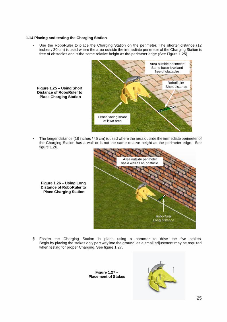
1.14 Placing and testing the Charging Station
• Use the RoboRuler to place the Charging Station on the perimeter. The shorter distance (12 inches / 30 cm) is used where the area outside the immediate perimeter of the Charging Station is free of obstacles and is the same relative height as the perimeter edge (See Figure 1.25).
• The longer distance (18 inches / 45 cm) is used where the area outside the immediate perimeter of the Charging Station has a wall or is not the same relative height as the perimeter edge. See figure 1.26.
§ Fasten the Charging Station in place using a hammer to drive the five stakes.
Begin by placing the stakes only part way into the ground, as a small adjustment may be required when testing for proper Charging. See figure 1.27.
RoboRuler Short distance
Fence facing inside of lawn area
Figure 1.25 – Using Short Distance of RoboRuler to
Place Charging Station
Figure 1.26 – Using Long Distance of RoboRuler to
Place Charging Station
Figure 1.27 – Placement of Stakes
Area outside perimeter: Same basic level and
free of obstacles.
RoboRuler Long distance
Area outside perimeter has a wall as an obstacle.
26
§ Test the Charging Station setup. Connect the power supply to a regular household receptacle 120 Volts AC (models outside the US use a 230 volt main power).
§ Press the ‘On’ button on the Charging Station Operation Panel.
§ A small flashing green light next to the ‘On’ button indicates the system is on and functioning correctly.
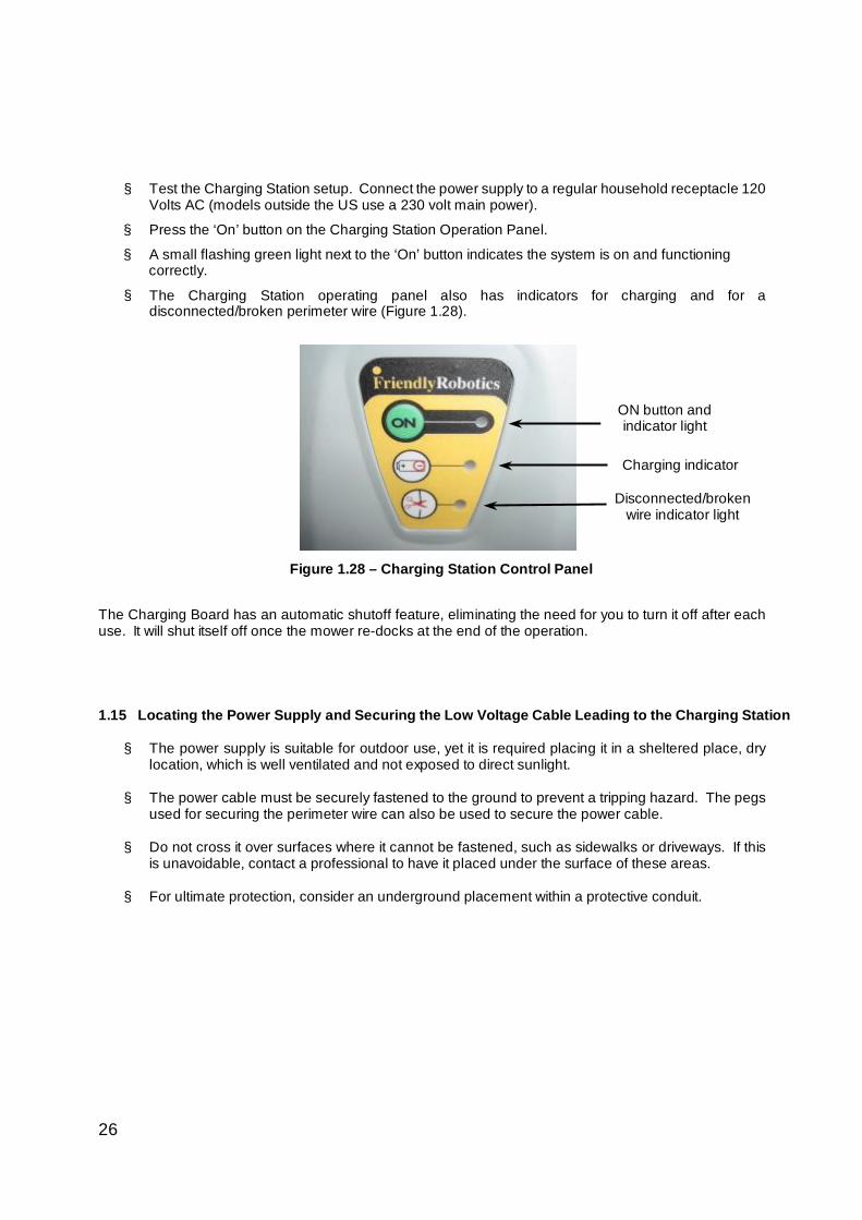
§ The Charging Station operating panel also has indicators for charging and for a disconnected/broken perimeter wire (Figure 1.28).
The Charging Board has an automatic shutoff feature, eliminating the need for you to turn it off after each use. It will shut itself off once the mower re-docks at the end of the operation.
1.15 Locating the Power Supply and Securing the Low Voltage Cable Leading to the Charging Station
§ The power supply is suitable for outdoor use, yet it is required placing it in a sheltered place, dry location, which is well ventilated and not exposed to direct sunlight.
§ The power cable must be securely fastened to the ground to prevent a tripping hazard. The pegs used for securing the perimeter wire can also be used to secure the power cable.
§ Do not cross it over surfaces where it cannot be fastened, such as sidewalks or driveways. If this is unavoidable, contact a professional to have it placed under the surface of these areas.
§ For ultimate protection, consider an underground placement within a protective conduit.
Figure 1.28 – Charging Station Control Panel
ON button and indicator light
Disconnected/broken wire indicator light
Charging indicator
27
Setup in Non-Charging Zone Note: Setup in a non-Charging zone requires a Perimeter Switch (available as an accessory - see Chapter 10 - Accessories). 1.16 Perimeter Switch Placement and Perimeter Wire Setup
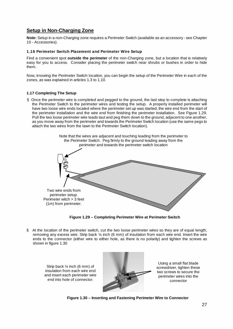
Find a convenient spot outside the perimeter of the non-Charging zone, but a location that is relatively easy for you to access. Consider placing the perimeter switch near shrubs or bushes in order to hide them. Now, knowing the Perimeter Switch location, you can begin the setup of the Perimeter Wire in each of the zones, as was explained in articles 1.3 to 1.10. 1.17 Completing The Setup § Once the perimeter wire is completed and pegged to the ground, the last step to complete is attaching
the Perimeter Switch to the perimeter wires and testing the setup. A properly installed perimeter will have two loose wire ends located where the perimeter set up was started; the wire end from the start of the perimeter installation and the wire end from finishing the perimeter installation. See Figure 1.29. Pull the two loose perimeter wire leads taut and peg them down to the ground, adjacent to one another, as you move away from the perimeter and towards the Perimeter Switch location (use the same pegs to attach the two wires from the lawn to the Perimeter Switch location).
§ At the location of the perimeter switch, cut the two loose perimeter wires so they are of equal length,
removing any excess wire. Strip back ¼ inch (6 mm) of insulation from each wire end. Insert the wire ends to the connector (either wire to either hole, as there is no polarity) and tighten the screws as shown in figure 1.30
Figure 1.30 – Inserting and Fastening Perimeter Wire to Connector
Strip back ¼ inch (6 mm) of insulation from each wire end and insert each perimeter wire
end into hole of connector.
Using a small flat blade screwdriver, tighten these two screws to secure the perimeter wires into the
connector
Figure 1.29 – Completing Perimeter Wire at Perimeter Switch
Two wire ends from perimeter setup.
Perimeter witch > 3 feet (1m) from perimeter.
Note that the wires are adjacent and touching leading from the perimeter to
the Perimeter Switch. Peg firmly to the ground leading away from the perimeter and towards the perimeter switch location
28
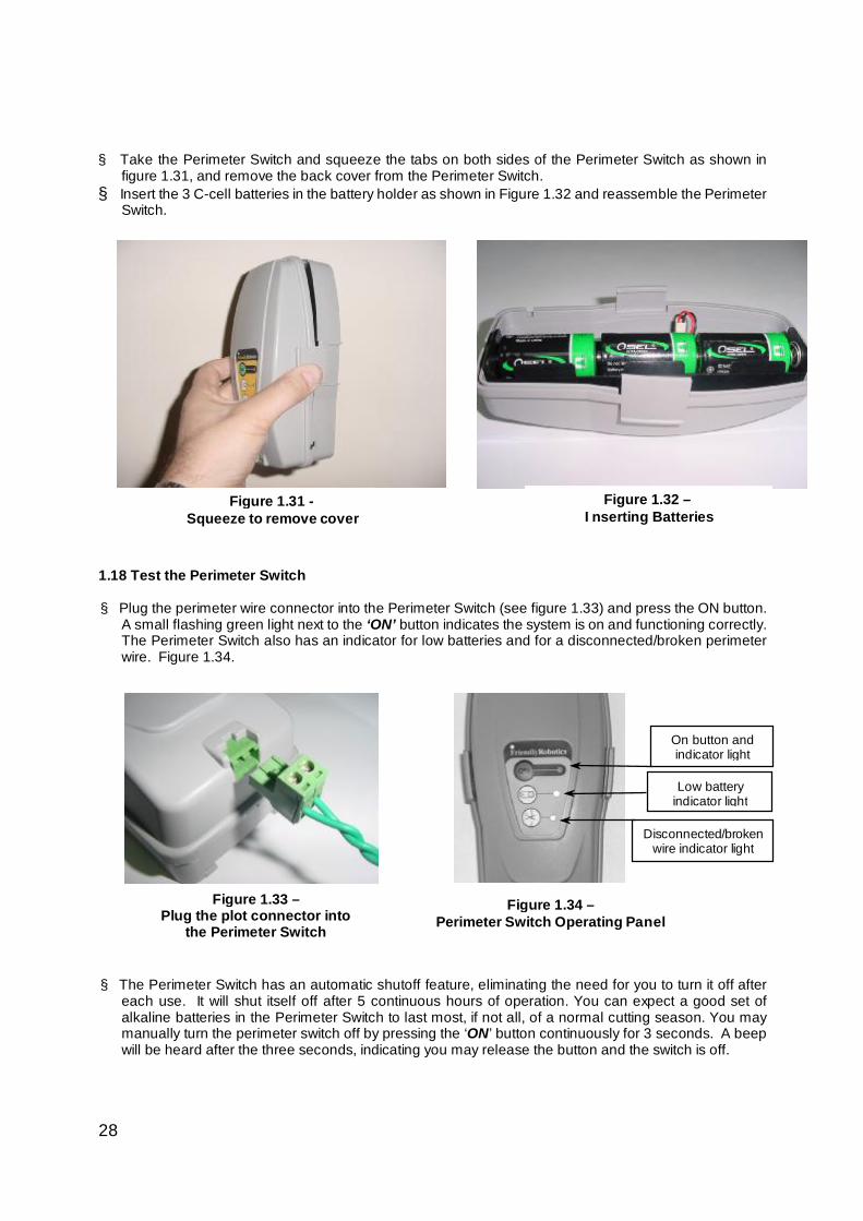
§ Take the Perimeter Switch and squeeze the tabs on both sides of the Perimeter Switch as shown in figure 1.31, and remove the back cover from the Perimeter Switch.
§ Insert the 3 C-cell batteries in the battery holder as shown in Figure 1.32 and reassemble the Perimeter Switch.
1.18 Test the Perimeter Switch § Plug the perimeter wire connector into the Perimeter Switch (see figure 1.33) and press the ON button.
A small flashing green light next to the ‘ON’ button indicates the system is on and functioning correctly. The Perimeter Switch also has an indicator for low batteries and for a disconnected/broken perimeter wire. Figure 1.34.
§ The Perimeter Switch has an automatic shutoff feature, eliminating the need for you to turn it off after
each use. It will shut itself off after 5 continuous hours of operation. You can expect a good set of alkaline batteries in the Perimeter Switch to last most, if not all, of a normal cutting season. You may manually turn the perimeter switch off by pressing the ‘ON’ button continuously for 3 seconds. A beep will be heard after the three seconds, indicating you may release the button and the switch is off.
Figure 1.34 – Perimeter Switch Operating Panel
Figure 1.32 – Inserting Batteries
Figure 1.31 - Squeeze to remove cover
On button and indicator light
Low battery indicator light
Disconnected/broken wire indicator light
Figure 1.33 – Plug the plot connector into
the Perimeter Switch
29
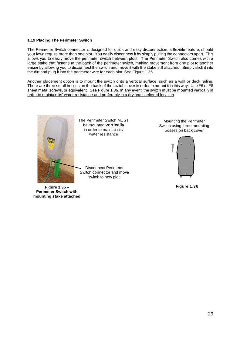
1.19 Placing The Perimeter Switch The Perimeter Switch connector is designed for quick and easy disconnection, a flexible feature, should your lawn require more than one plot. You easily disconnect it by simply pulling the connectors apart. This allows you to easily move the perimeter switch between plots. The Perimeter Switch also comes with a large stake that fastens to the back of the perimeter switch, making movement from one plot to another easier by allowing you to disconnect the switch and move it with the stake still attached. Simply stick it into the dirt and plug it into the perimeter wire for each plot. See Figure 1.35
Another placement option is to mount the switch onto a vertical surface, such as a wall or deck railing. There are three small bosses on the back of the switch cover in order to mount it in this way. Use #6 or #8 sheet metal screws, or equivalent. See Figure 1.36. In any event, the switch must be mounted vertically in order to maintain its’ water resistance and preferably in a dry and sheltered location.
Mounting the Perimeter Switch using three mounting
bosses on back cover
Figure 1.36
The Perimeter Switch MUST be mounted vertically in order to maintain its’
water resistance
Disconnect Perimeter Switch connector and move
switch to new plot.
Figure 1.35 – Perimeter Switch with
mounting stake attached
30
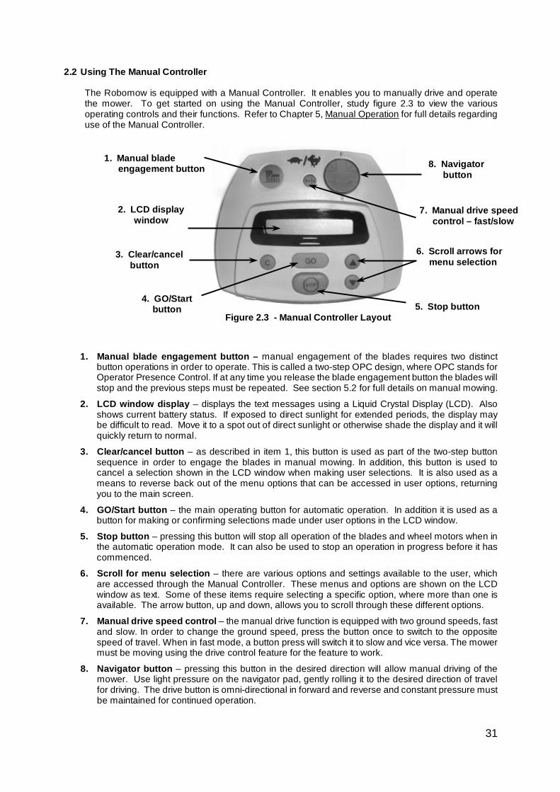
Insert the Power Pack fuse into the fuse holder. The fuse can be inserted
in either direction Contacts
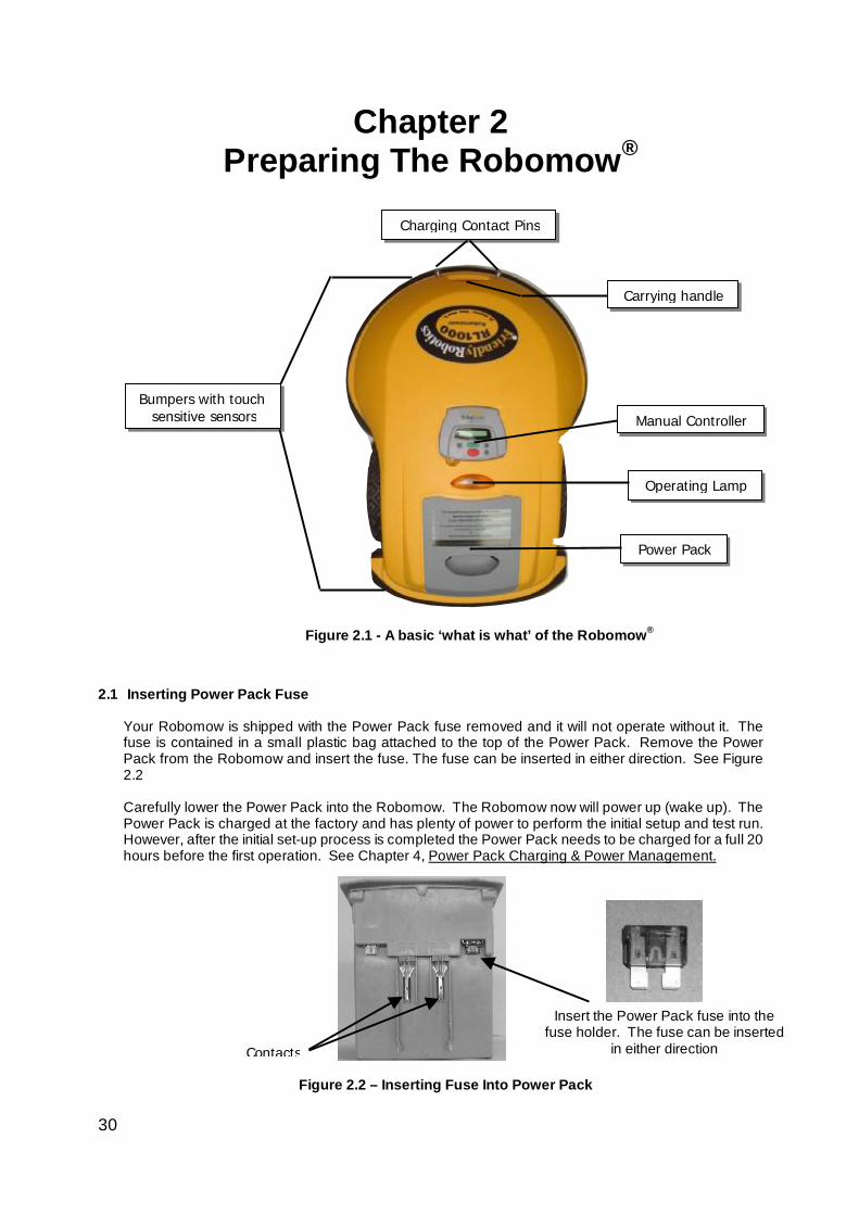
Bumpers with touch sensitive sensors Manual Controller
Power Pack
Operating Lamp
Chapter 2 Preparing The Robomow®
2.1 Inserting Power Pack Fuse
Your Robomow is shipped with the Power Pack fuse removed and it will not operate without it. The fuse is contained in a small plastic bag attached to the top of the Power Pack. Remove the Power Pack from the Robomow and insert the fuse. The fuse can be inserted in either direction. See Figure 2.2 Carefully lower the Power Pack into the Robomow. The Robomow now will power up (wake up). The Power Pack is charged at the factory and has plenty of power to perform the initial setup and test run. However, after the initial set-up process is completed the Power Pack needs to be charged for a full 20 hours before the first operation. See Chapter 4, Power Pack Charging & Power Management.
Figure 2.2 – Inserting Fuse Into Power Pack
Figure 2.1 - A basic ‘what is what’ of the Robomow®
Carrying handle
Charging Contact Pins
31
2.2 Using The Manual Controller
The Robomow is equipped with a Manual Controller. It enables you to manually drive and operate the mower. To get started on using the Manual Controller, study figure 2.3 to view the various operating controls and their functions. Refer to Chapter 5, Manual Operation for full details regarding use of the Manual Controller.
1. Manual blade engagement button – manual engagement of the blades requires two distinct
button operations in order to operate. This is called a two-step OPC design, where OPC stands for Operator Presence Control. If at any time you release the blade engagement button the blades will stop and the previous steps must be repeated. See section 5.2 for full details on manual mowing.
2. LCD window display – displays the text messages using a Liquid Crystal Display (LCD). Also shows current battery status. If exposed to direct sunlight for extended periods, the display may be difficult to read. Move it to a spot out of direct sunlight or otherwise shade the display and it will quickly return to normal.
3. Clear/cancel button – as described in item 1, this button is used as part of the two-step button sequence in order to engage the blades in manual mowing. In addition, this button is used to cancel a selection shown in the LCD window when making user selections. It is also used as a means to reverse back out of the menu options that can be accessed in user options, returning you to the main screen.
4. GO/Start button – the main operating button for automatic operation. In addition it is used as a button for making or confirming selections made under user options in the LCD window.
5. Stop button – pressing this button will stop all operation of the blades and wheel motors when in the automatic operation mode. It can also be used to stop an operation in progress before it has commenced.
6. Scroll for menu selection – there are various options and settings available to the user, which are accessed through the Manual Controller. These menus and options are shown on the LCD window as text. Some of these items require selecting a specific option, where more than one is available. The arrow button, up and down, allows you to scroll through these different options.
7. Manual drive speed control – the manual drive function is equipped with two ground speeds, fast and slow. In order to change the ground speed, press the button once to switch to the opposite speed of travel. When in fast mode, a button press will switch it to slow and vice versa. The mower must be moving using the drive control feature for the feature to work.
8. Navigator button – pressing this button in the desired direction will allow manual driving of the mower. Use light pressure on the navigator pad, gently rolling it to the desired direction of travel for driving. The drive button is omni-directional in forward and reverse and constant pressure must be maintained for continued operation.
Figure 2.3 - Manual Controller Layout
4. GO/Start button
2. LCD display window
8. Navigator button
6. Scroll arrows for menu selection
5. Stop button
3. Clear/cancel button
1. Manual blade engagement button
7. Manual drive speed control – fast/slow
32
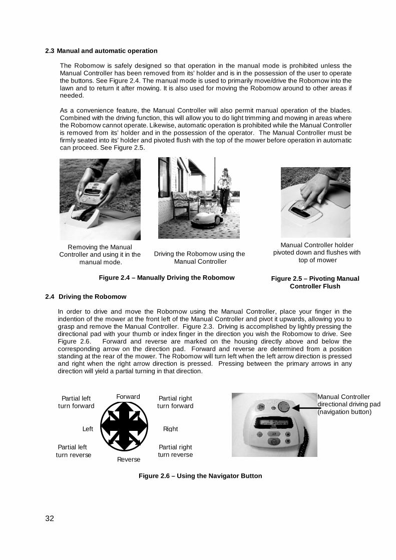
2.3 Manual and automatic operation
The Robomow is safely designed so that operation in the manual mode is prohibited unless the Manual Controller has been removed from its’ holder and is in the possession of the user to operate the buttons. See Figure 2.4. The manual mode is used to primarily move/drive the Robomow into the lawn and to return it after mowing. It is also used for moving the Robomow around to other areas if needed. As a convenience feature, the Manual Controller will also permit manual operation of the blades. Combined with the driving function, this will allow you to do light trimming and mowing in areas where the Robomow cannot operate. Likewise, automatic operation is prohibited while the Manual Controller is removed from its’ holder and in the possession of the operator. The Manual Controller must be firmly seated into its’ holder and pivoted flush with the top of the mower before operation in automatic can proceed. See Figure 2.5.
2.4 Driving the Robomow
In order to drive and move the Robomow using the Manual Controller, place your finger in the indention of the mower at the front left of the Manual Controller and pivot it upwards, allowing you to grasp and remove the Manual Controller. Figure 2.3. Driving is accomplished by lightly pressing the directional pad with your thumb or index finger in the direction you wish the Robomow to drive. See Figure 2.6. Forward and reverse are marked on the housing directly above and below the corresponding arrow on the direction pad. Forward and reverse are determined from a position standing at the rear of the mower. The Robomow will turn left when the left arrow direction is pressed and right when the right arrow direction is pressed. Pressing between the primary arrows in any direction will yield a partial turning in that direction.
Removing the Manual Controller and using it in the
manual mode.
Figure 2.4 – Manually Driving the Robomow Figure 2.5 – Pivoting Manual Controller Flush
Manual Controller directional driving pad (navigation button)
Forward
Reverse
Left Right
Partial right turn forward
Partial left turn forward
Partial right turn reverse
Partial left turn reverse
Figure 2.6 – Using the Navigator Button
Driving the Robomow using the Manual Controller
Manual Controller holder pivoted down and flushes with
top of mower
33
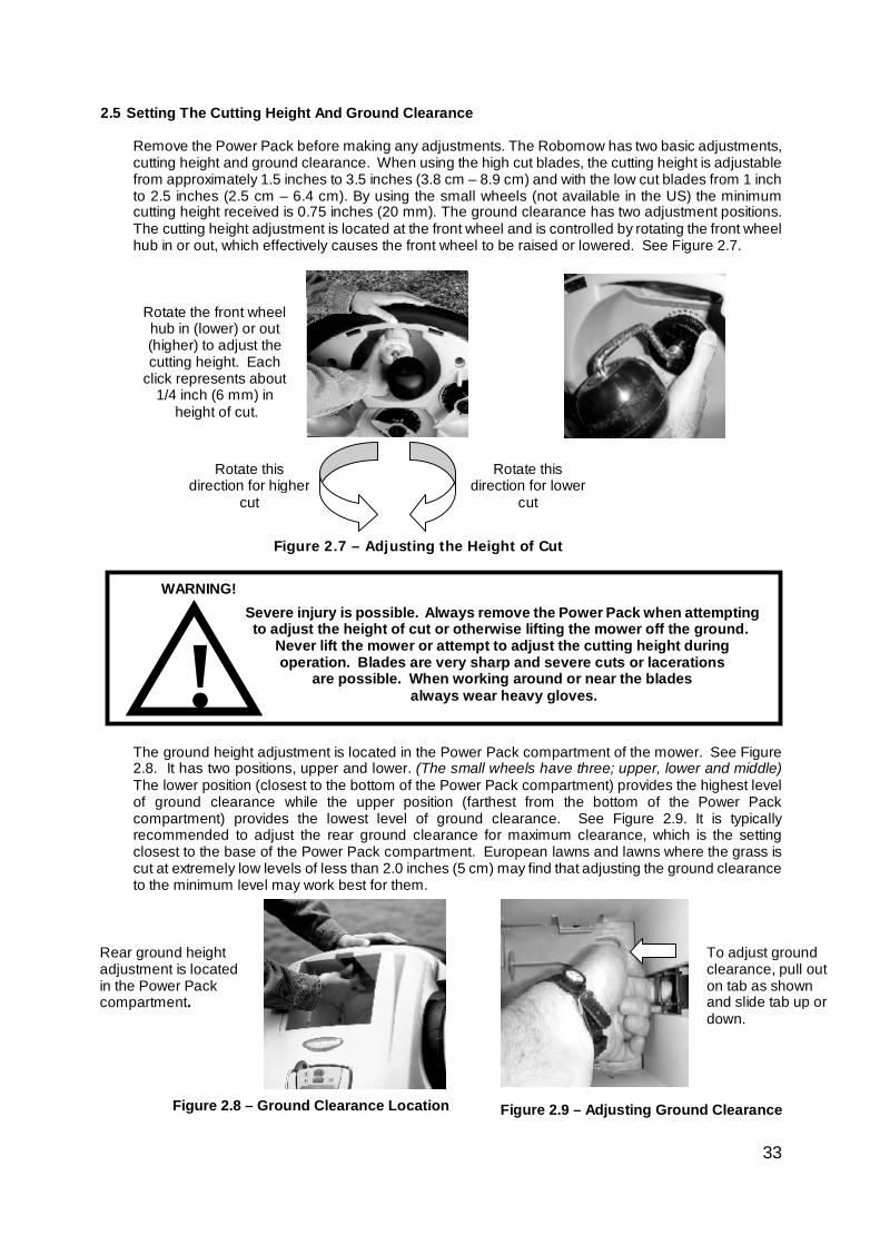
Severe injury is possible. Always remove the Power Pack when attempting to adjust the height of cut or otherwise lifting the mower off the ground.
Never lift the mower or attempt to adjust the cutting height during operation. Blades are very sharp and severe cuts or lacerations
are possible. When working around or near the blades always wear heavy gloves. !
WARNING!
2.5 Setting The Cutting Height And Ground Clearance
Remove the Power Pack before making any adjustments. The Robomow has two basic adjustments, cutting height and ground clearance. When using the high cut blades, the cutting height is adjustable from approximately 1.5 inches to 3.5 inches (3.8 cm – 8.9 cm) and with the low cut blades from 1 inch to 2.5 inches (2.5 cm – 6.4 cm). By using the small wheels (not available in the US) the minimum cutting height received is 0.75 inches (20 mm). The ground clearance has two adjustment positions. The cutting height adjustment is located at the front wheel and is controlled by rotating the front wheel hub in or out, which effectively causes the front wheel to be raised or lowered. See Figure 2.7.
The ground height adjustment is located in the Power Pack compartment of the mower. See Figure 2.8. It has two positions, upper and lower. (The small wheels have three; upper, lower and middle) The lower position (closest to the bottom of the Power Pack compartment) provides the highest level of ground clearance while the upper position (farthest from the bottom of the Power Pack compartment) provides the lowest level of ground clearance. See Figure 2.9. It is typically recommended to adjust the rear ground clearance for maximum clearance, which is the setting closest to the base of the Power Pack compartment. European lawns and lawns where the grass is cut at extremely low levels of less than 2.0 inches (5 cm) may find that adjusting the ground clearance to the minimum level may work best for them.
Figure 2.7 – Adjusting the Height of Cut
Figure 2.8 – Ground Clearance Location Figure 2.9 – Adjusting Ground Clearance
Rear ground height adjustment is located in the Power Pack compartment.
To adjust ground clearance, pull out on tab as shown and slide tab up or down.
Rotate the front wheel hub in (lower) or out (higher) to adjust the cutting height. Each
click represents about 1/4 inch (6 mm) in
height of cut.
Rotate this direction for lower
cut
Rotate this direction for higher
cut
34
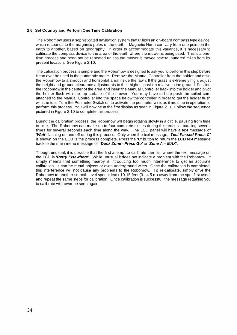
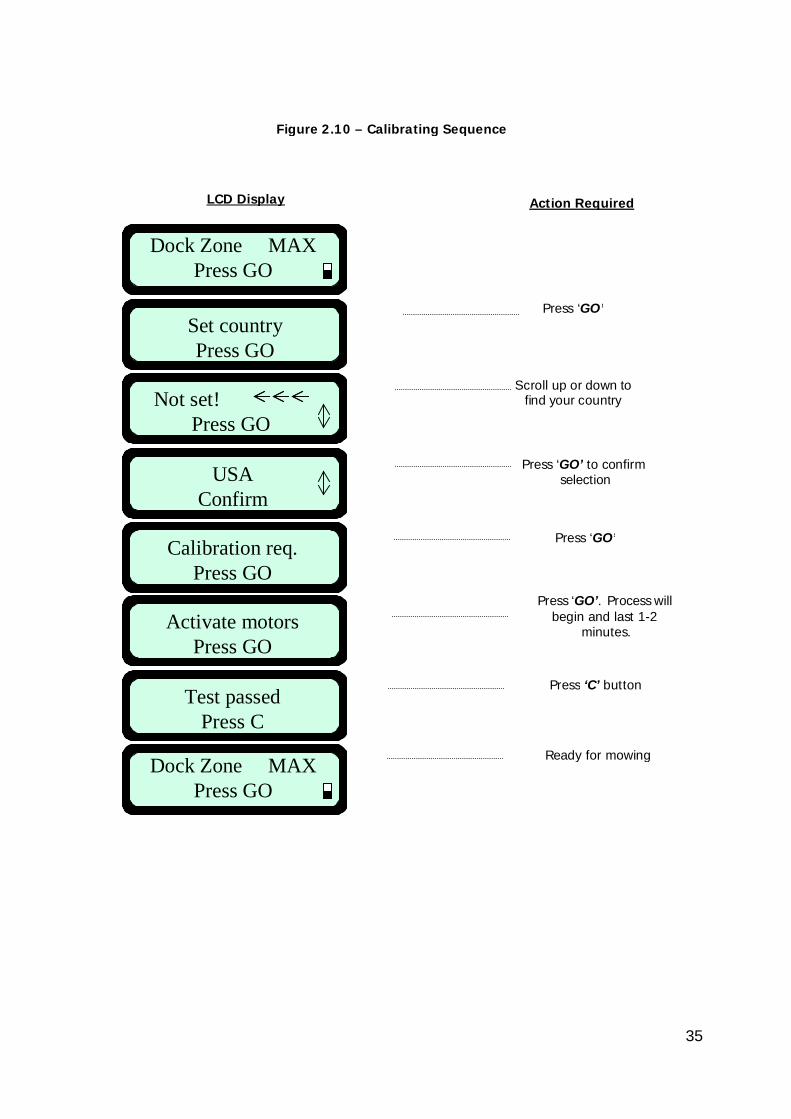
2.6 Set Country and Perform One Time Calibration
The Robomow uses a sophisticated navigation system that utilizes an on-board compass type device, which responds to the magnetic poles of the earth. Magnetic North can vary from one point on the earth to another, based on geography. In order to accommodate this variance, it is necessary to calibrate the compass device to the area of the earth where the mower is being used. This is a one-time process and need not be repeated unless the mower is moved several hundred miles from its’ present location. See Figure 2.10. The calibration process is simple and the Robomow is designed to ask you to perform this step before it can ever be used in the automatic mode. Remove the Manual Controller from the holder and drive the Robomow to a smooth and horizontal area inside the lawn. If the grass is extremely high, adjust the height and ground clearance adjustments to their highest position relative to the ground. Position the Robomow in the center of the area and insert the Manual Controller back into the holder and pivot the holder flush with the top surface of the mower. You may have to help push the coiled cord attached to the Manual Controller into the space below the controller in order to get the holder flush with the top. Turn the Perimeter Switch on to activate the perimeter wire, as it must be in operation to perform this process. You will now be at the first display as seen in Figure 2.10. Follow the sequence pictured in Figure 2.10 to complete this process. During the calibration process, the Robomow will begin rotating slowly in a circle, pausing from time to time. The Robomow can make up to four complete circles during this process, pausing several times for several seconds each time along the way. The LCD panel will have a text message of ‘Wait’ flashing on and off during this process. Only when the text message, ‘Test Passed Press C’ is shown on the LCD is the process complete. Press the ‘C’ button to return the LCD text message back to the main menu message of ‘Dock Zone - Press Go’ or ‘Zone A – MAX’. Though unusual, it is possible that the first attempt to calibrate can fail, where the text message on the LCD is ‘Retry Elsewhere’. While unusual it does not indicate a problem with the Robomow. It simply means that something nearby is introducing too much interference to get an accurate calibration. It can be metal objects or even underground wires. Once the calibration is completed, this interference will not cause any problems to the Robomow. To re-calibrate, simply drive the Robomow to another smooth level spot at least 10-15 feet (3 - 4.5 m) away from the spot first used, and repeat the same steps for calibration. Once calibration is successful, the message requiring you to calibrate will never be seen again.
35
Dock Zone MAXPress GO
Set countryPress GO
USAConfirm
Calibration req.Press GO
Not set! Press GO
Activate motorsPress GO
Test passedPress C
Dock Zone MAXPress GO
Dock Zone MAXPress GO
Set countryPress GO
USAConfirm
Calibration req.Press GO
Not set! Press GO
Activate motorsPress GO
Test passedPress C
Dock Zone MAXPress GO
LCD Display Action Required
Figure 2.10 – Calibrating Sequence
Press ‘GO’
Scroll up or down to find your country
Press ‘GO’ to confirm selection
Press ‘GO’
Press ‘GO’. Process will begin and last 1-2
minutes.
Press ‘C’ button
Ready for mowing
36
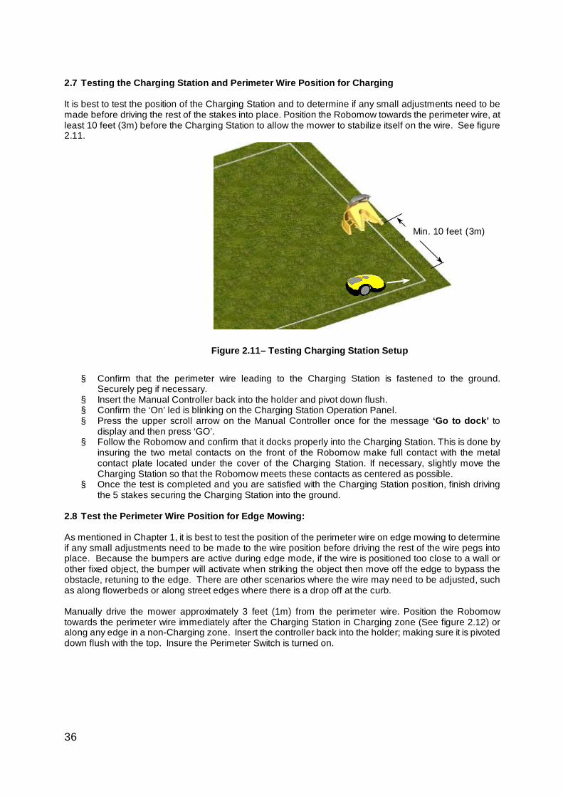
2.7 Testing the Charging Station and Perimeter Wire Position for Charging It is best to test the position of the Charging Station and to determine if any small adjustments need to be made before driving the rest of the stakes into place. Position the Robomow towards the perimeter wire, at least 10 feet (3m) before the Charging Station to allow the mower to stabilize itself on the wire. See figure 2.11.
§ Confirm that the perimeter wire leading to the Charging Station is fastened to the ground.
Securely peg if necessary. § Insert the Manual Controller back into the holder and pivot down flush. § Confirm the ‘On’ led is blinking on the Charging Station Operation Panel. § Press the upper scroll arrow on the Manual Controller once for the message ‘Go to dock’ to
display and then press ‘GO’. § Follow the Robomow and confirm that it docks properly into the Charging Station. This is done by
insuring the two metal contacts on the front of the Robomow make full contact with the metal contact plate located under the cover of the Charging Station. If necessary, slightly move the Charging Station so that the Robomow meets these contacts as centered as possible.
§ Once the test is completed and you are satisfied with the Charging Station position, finish driving the 5 stakes securing the Charging Station into the ground.
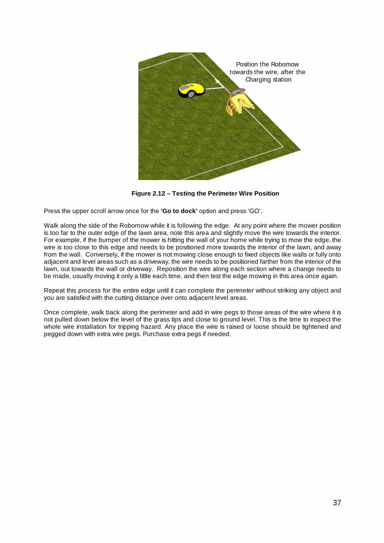
2.8 Test the Perimeter Wire Position for Edge Mowing: As mentioned in Chapter 1, it is best to test the position of the perimeter wire on edge mowing to determine if any small adjustments need to be made to the wire position before driving the rest of the wire pegs into place. Because the bumpers are active during edge mode, if the wire is positioned too close to a wall or other fixed object, the bumper will activate when striking the object then move off the edge to bypass the obstacle, retuning to the edge. There are other scenarios where the wire may need to be adjusted, such as along flowerbeds or along street edges where there is a drop off at the curb. Manually drive the mower approximately 3 feet (1m) from the perimeter wire. Position the Robomow towards the perimeter wire immediately after the Charging Station in Charging zone (See figure 2.12) or along any edge in a non-Charging zone. Insert the controller back into the holder; making sure it is pivoted down flush with the top. Insure the Perimeter Switch is turned on.
Figure 2.11– Testing Charging Station Setup
Min. 10 feet (3m)
37
Press the upper scroll arrow once for the ‘Go to dock’ option and press ‘GO’. Walk along the side of the Robomow while it is following the edge. At any point where the mower position is too far to the outer edge of the lawn area, note this area and slightly move the wire towards the interior. For example, if the bumper of the mower is hitting the wall of your home while trying to mow the edge, the wire is too close to this edge and needs to be positioned more towards the interior of the lawn, and away from the wall. Conversely, if the mower is not mowing close enough to fixed objects like walls or fully onto adjacent and level areas such as a driveway, the wire needs to be positioned farther from the interior of the lawn, out towards the wall or driveway. Reposition the wire along each section where a change needs to be made, usually moving it only a little each time, and then test the edge mowing in this area once again. Repeat this process for the entire edge until it can complete the perimeter without striking any object and you are satisfied with the cutting distance over onto adjacent level areas. Once complete, walk back along the perimeter and add in wire pegs to those areas of the wire where it is not pulled down below the level of the grass tips and close to ground level. This is the time to inspect the whole wire installation for tripping hazard. Any place the wire is raised or loose should be tightened and pegged down with extra wire pegs. Purchase extra pegs if needed.
Figure 2.12 – Testing the Perimeter Wire Position
Position the Robomow towards the wire, after the
Charging station
38
Chapter 3 Manual and Automatic Operation
3.1 Activating The Perimeter Switch – Charging Zone
Area/zone with Charging Station
§ If the Robomow is operated from the Charging Station in automatic or manual-depart (see paragraphs 3.2 and 3.3), the Robomow will automatically switch the Perimeter Switch/docking board at the Charging Station Control Panel on and off to coincide with depart and dock events.
3.2 Manual Depart
Manual Depart mode can be used in cases such as the following:
- Mowing the lawn at times other than when programmed. - When the lawn is occupied and the yard must be cleared of debris, objects, pets or people first.
§ For initiating a manual start for mowing, press the ‘GO’ button once to start the sequence:
1. If entry points were set (see 6.4.1), you will be asked to select the entry point for the current operation.
2. Robomow will depart from the Charging Station and automatically follow the perimeter wire one pass around the perimeter until it reaches the Charging Station. It will briefly start to dock, but then reverse out and move back to continue the mowing of the inner area.
3. Robomow will automatically determine the entry point into the lawn from the perimeter wire. A ‘Searching entry’ message is displayed on the Manual Controller while it is searching for the entry point into the lawn. The RL1000 is programmed for three different entry points into the lawn, at specified distances from the Charging Station. It will go to the next entry point with each operation until it begins at location one again.
§ To skip the edge mowing process, press the ‘GO’ button twice when initiating manual depart
and mowing. 3.3 Automatic Depart
§ Automatic Depart mode is used as fully automatic solution to maintain your lawn.
§ This mode enables you to set a weekly program, where the mower will automatically depart to mow and dock when finished, at days and times you have scheduled.
§ To set the weekly program refer to Chapter 4, Setting the Weekly Program.
3.4 Returning to the Charging Station § Automatic Charging
The Robomow automatically returns to the Charging Station at the end of every operation. It will recharge and stay ready for the next scheduled departure time that was scheduled.
§ ‘Go to Dock’ option
You can manually send the mower to the Charging Station from any point in the lawn.
WARNING!
! Never let Robomow operate without supervision. Serious injury can occur. Insure that the scheduled operating times that you program in for automatic departure and mowing are times when the mowing area will be free of children and pets. Do not program times unless you are certain the area will be free of children, pets and bystanders.
39
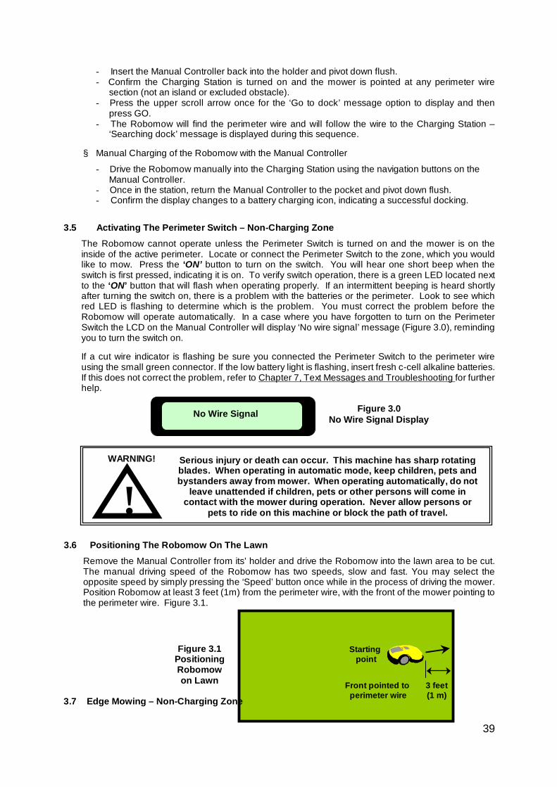
Figure 3.1 Positioning Robomow on Lawn
Front pointed to perimeter wire
Starting point
3 feet (1 m)
- Insert the Manual Controller back into the holder and pivot down flush. - Confirm the Charging Station is turned on and the mower is pointed at any perimeter wire
section (not an island or excluded obstacle). - Press the upper scroll arrow once for the ‘Go to dock’ message option to display and then
press GO. - The Robomow will find the perimeter wire and will follow the wire to the Charging Station –
‘Searching dock’ message is displayed during this sequence.
§ Manual Charging of the Robomow with the Manual Controller
- Drive the Robomow manually into the Charging Station using the navigation buttons on the Manual Controller.
- Once in the station, return the Manual Controller to the pocket and pivot down flush. - Confirm the display changes to a battery charging icon, indicating a successful docking.
3.5 Activating The Perimeter Switch – Non-Charging Zone The Robomow cannot operate unless the Perimeter Switch is turned on and the mower is on the inside of the active perimeter. Locate or connect the Perimeter Switch to the zone, which you would like to mow. Press the ‘ON’ button to turn on the switch. You will hear one short beep when the switch is first pressed, indicating it is on. To verify switch operation, there is a green LED located next to the ‘ON’ button that will flash when operating properly. If an intermittent beeping is heard shortly after turning the switch on, there is a problem with the batteries or the perimeter. Look to see which red LED is flashing to determine which is the problem. You must correct the problem before the Robomow will operate automatically. In a case where you have forgotten to turn on the Perimeter Switch the LCD on the Manual Controller will display ‘No wire signal’ message (Figure 3.0), reminding you to turn the switch on. If a cut wire indicator is flashing be sure you connected the Perimeter Switch to the perimeter wire using the small green connector. If the low battery light is flashing, insert fresh c-cell alkaline batteries. If this does not correct the problem, refer to Chapter 7, Text Messages and Troubleshooting for further help.
3.6 Positioning The Robomow On The Lawn
Remove the Manual Controller from its’ holder and drive the Robomow into the lawn area to be cut. The manual driving speed of the Robomow has two speeds, slow and fast. You may select the opposite speed by simply pressing the ‘Speed’ button once while in the process of driving the mower. Position Robomow at least 3 feet (1m) from the perimeter wire, with the front of the mower pointing to the perimeter wire. Figure 3.1.
3.7 Edge Mowing – Non-Charging Zone
No Wire Signal Figure 3.0 No Wire Signal Display
! WARNING!
Serious injury or death can occur. This machine has sharp rotating blades. When operating in automatic mode, keep children, pets and bystanders away from mower. When operating automatically, do not
leave unattended if children, pets or other persons will come in contact with the mower during operation. Never allow persons or
pets to ride on this machine or block the path of travel.
Chapter 3 Page 28
40
Figure 3.2 Edge Mowing
Edge RoboScan2
Mowing RoboScan2
Starting point
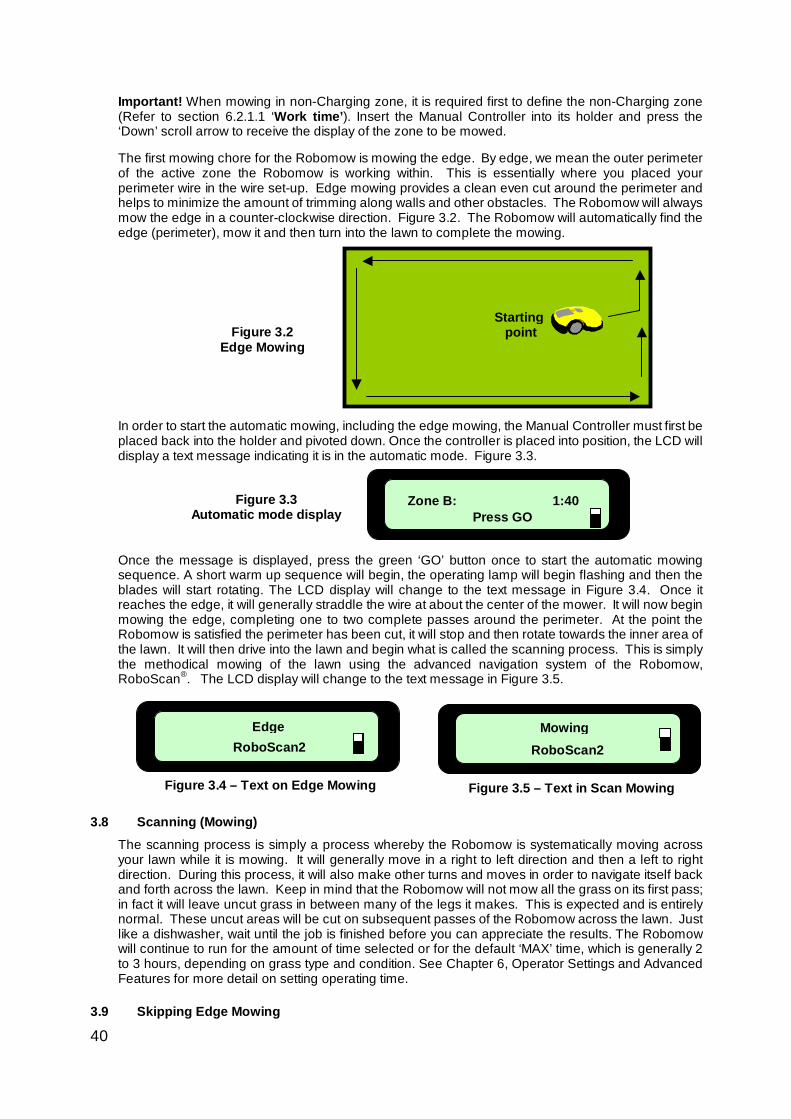
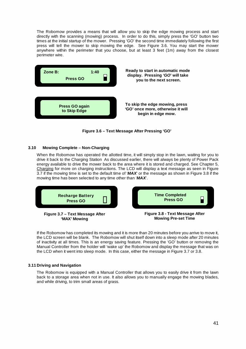
Important! When mowing in non-Charging zone, it is required first to define the non-Charging zone (Refer to section 6.2.1.1 ‘Work time’). Insert the Manual Controller into its holder and press the ‘Down’ scroll arrow to receive the display of the zone to be mowed. The first mowing chore for the Robomow is mowing the edge. By edge, we mean the outer perimeter of the active zone the Robomow is working within. This is essentially where you placed your perimeter wire in the wire set-up. Edge mowing provides a clean even cut around the perimeter and helps to minimize the amount of trimming along walls and other obstacles. The Robomow will always mow the edge in a counter-clockwise direction. Figure 3.2. The Robomow will automatically find the edge (perimeter), mow it and then turn into the lawn to complete the mowing. In order to start the automatic mowing, including the edge mowing, the Manual Controller must first be placed back into the holder and pivoted down. Once the controller is placed into position, the LCD will display a text message indicating it is in the automatic mode. Figure 3.3.
Once the message is displayed, press the green ‘GO’ button once to start the automatic mowing sequence. A short warm up sequence will begin, the operating lamp will begin flashing and then the blades will start rotating. The LCD display will change to the text message in Figure 3.4. Once it reaches the edge, it will generally straddle the wire at about the center of the mower. It will now begin mowing the edge, completing one to two complete passes around the perimeter. At the point the Robomow is satisfied the perimeter has been cut, it will stop and then rotate towards the inner area of the lawn. It will then drive into the lawn and begin what is called the scanning process. This is simply the methodical mowing of the lawn using the advanced navigation system of the Robomow, RoboScan®. The LCD display will change to the text message in Figure 3.5.
3.8 Scanning (Mowing)
The scanning process is simply a process whereby the Robomow is systematically moving across your lawn while it is mowing. It will generally move in a right to left direction and then a left to right direction. During this process, it will also make other turns and moves in order to navigate itself back and forth across the lawn. Keep in mind that the Robomow will not mow all the grass on its first pass; in fact it will leave uncut grass in between many of the legs it makes. This is expected and is entirely normal. These uncut areas will be cut on subsequent passes of the Robomow across the lawn. Just like a dishwasher, wait until the job is finished before you can appreciate the results. The Robomow will continue to run for the amount of time selected or for the default ‘MAX’ time, which is generally 2 to 3 hours, depending on grass type and condition. See Chapter 6, Operator Settings and Advanced Features for more detail on setting operating time.
3.9 Skipping Edge Mowing
Figure 3.3 Automatic mode display
Figure 3.4 – Text on Edge Mowing Figure 3.5 – Text in Scan Mowing
Zone B: 1:40 Press GO
41
The Robomow provides a means that will allow you to skip the edge mowing process and start directly with the scanning (mowing) process. In order to do this, simply press the ‘GO’ button two times at the initial startup of the mower. Pressing ‘GO’ the second time immediately following the first press will tell the mower to skip mowing the edge. See Figure 3.6. You may start the mower anywhere within the perimeter that you choose, but at least 3 feet (1m) away from the closest perimeter wire.
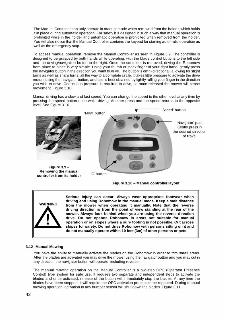
3.10 Mowing Complete – Non-Charging
When the Robomow has operated the allotted time, it will simply stop in the lawn, waiting for you to drive it back to the Charging Station As discussed earlier, there will always be plenty of Power Pack energy available to drive the mower back to the area where it is stored and charged. See Chapter 5, Charging for more on charging instructions. The LCD will display a text message as seen in Figure 3.7 if the mowing time is set to the default time of ‘MAX’ or the message as shown in Figure 3.8 if the mowing time has been selected to any time other than ‘MAX’.
If the Robomow has completed its mowing and it is more than 20 minutes before you arrive to move it, the LCD screen will be blank. The Robomow will shut itself down into a sleep mode after 20 minutes of inactivity at all times. This is an energy saving feature. Pressing the ‘GO’ button or removing the Manual Controller from the holder will ‘wake up’ the Robomow and display the message that was on the LCD when it went into sleep mode. In this case, either the message in Figure 3.7 or 3.8.
3.11 Driving and Navigation
The Robomow is equipped with a Manual Controller that allows you to easily drive it from the lawn back to a storage area when not in use. It also allows you to manually engage the mowing blades, and while driving, to trim small areas of grass.
Figure 3.7 – Text Message After ‘MAX’ Mowing
Recharge Battery Press GO
Figure 3.8 - Text Message After Mowing Pre-set Time
Time Completed Press GO
Zone B: 1:40 Press GO
Press GO again to Skip Edge
Ready to start in automatic mode display. Pressing ‘GO’ will take
you to the next screen.
To skip the edge mowing, press ‘GO’ once more, otherwise it will
begin in edge mow.
Figure 3.6 – Text Message After Pressing ‘GO’
42
Figure 3.9 – Removing the manual
controller from its holder
‘C’ button
‘Navigator’ pad. Gently press in
the desired direction of travel
‘Mow’ button
‘Speed’ button
Figure 3.10 – Manual controller layout
The Manual Controller can only operate in manual mode when removed from the holder, which holds it in place during automatic operation. For safety it is designed in such a way that manual operation is prohibited while in the holder and automatic operation is prohibited when removed from the holder. You will also notice that the Manual Controller contains the keypad for starting automatic operation as well as the emergency stop. To access manual operation, remove the Manual Controller as seen in Figure 3.9. The controller is designed to be grasped by both hands while operating, with the blade control buttons to the left side and the driving/navigation button to the right. Once the controller is removed, driving the Robomow from place to place is very simple. Using your thumb or index finger of your right hand, gently press the navigator button in the direction you want to drive. The button is omni-directional, allowing for slight turns as well as sharp turns, all the way to a complete circle. It takes little pressure to activate the drive motors using the navigator button, and use is best obtained by lightly rolling your finger in the direction you wish to drive. Continuous pressure is required to drive, so once released the mower will cease movement. Figure 3.10. Manual driving has a slow and fast speed. You can change the speed to the other level at any time by pressing the speed button once while driving. Another press and the speed returns to the opposite level. See Figure 3.10.
3.12 Manual Mowing
You have the ability to manually activate the blades on the Robomow in order to trim small areas. After the blades are activated you may drive the mower using the navigator button and you may cut in any direction the navigator button will operate, including reverse. The manual mowing operation on the Manual Controller is a two-step OPC (Operator Presence Control) type system for safe use. It requires two separate and independent steps to activate the blades and once activated, release of the button will immediately stop the blades. At any time the blades have been stopped, it will require the OPC activation process to be repeated. During manual mowing operation, activation to any bumper sensor will shut down the blades. Figure 3.11.
WARNING!
! Serious injury can occur. Always wear appropriate footwear when driving and using Robomow in the manual mode. Keep a safe distance from the mower when operating it manually. Note that the reverse driving direction is from the point of view standing at the rear of the mower. Always look behind when you are using the reverse direction drive. Do not operate Robomow in areas not suitable for manual operation or on slopes where a sure footing is not possible. Cut across slopes for safety. Do not drive Robomow with persons sitting on it and do not manually operate within 10 feet (3m) of other persons or pets.
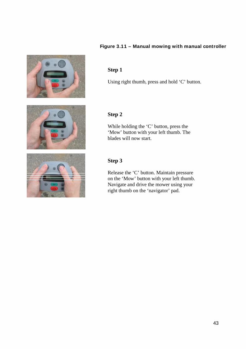
43
Figure 3.11 – Manual mowing with manual controller
Step 1 Using right thumb, press and hold ‘C’ button.
Step 2 While holding the ‘C’ button, press the ‘Mow’ button with your left thumb. The blades will now start.
Step 3 Release the ‘C’ button. Maintain pressure on the ‘Mow’ button with your left thumb. Navigate and drive the mower using your right thumb on the ‘navigator’ pad.
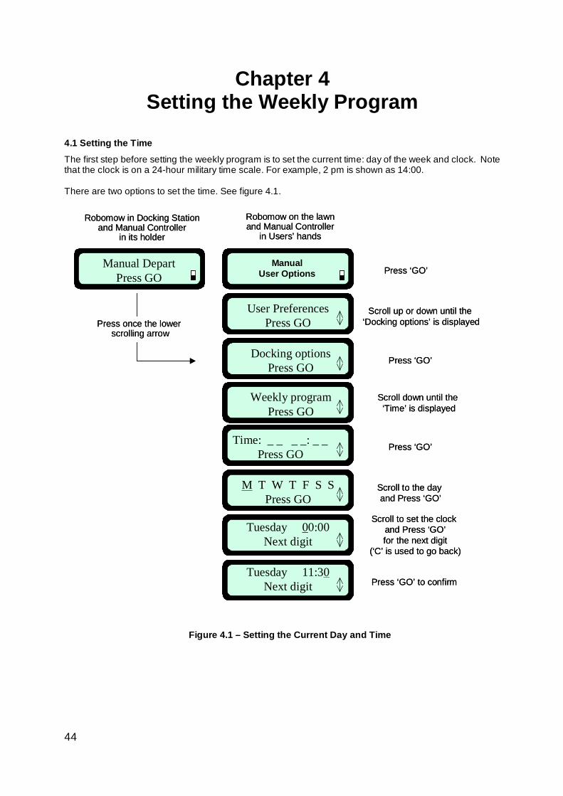
44
ManualUser Options
User PreferencesPress GO
Manual DepartPress GO
Robomow on the lawnand Manual Controller
in Users’ hands
Robomow in Docking Stationand Manual Controller
in its holder
Docking optionsPress GO
Press once the lowerscrolling arrow
Press ‘GO’
Scroll up or down until the ‘Docking options’ is displayed
Time: _ _ _ _: _ _Press GO
Press ‘GO’
Press ‘GO’
M T W T F S SPress GO
Scroll to the day and Press ‘GO’
Tuesday 00:00Next digit
Scroll to set the clock and Press ‘GO’for the next digit
(‘C’ is used to go back)
Tuesday 11:30Next digit Press ‘GO’ to confirm
Weekly programPress GO
Scroll down until the ‘Time’ is displayed
ManualUser Options
ManualUser Options
User PreferencesPress GO
Manual DepartPress GO
Robomow on the lawnand Manual Controller
in Users’ hands
Robomow in Docking Stationand Manual Controller
in its holder
Docking optionsPress GO
Press once the lowerscrolling arrow
Press ‘GO’
Scroll up or down until the ‘Docking options’ is displayed
Time: _ _ _ _: _ _Press GO
Press ‘GO’
Press ‘GO’
M T W T F S SPress GO
Scroll to the day and Press ‘GO’
Tuesday 00:00Next digit
Scroll to set the clock and Press ‘GO’for the next digit
(‘C’ is used to go back)
Tuesday 11:30Next digit Press ‘GO’ to confirm
Weekly programPress GO
Scroll down until the ‘Time’ is displayed
Chapter 4 Setting the Weekly Program
4.1 Setting the Time
The first step before setting the weekly program is to set the current time: day of the week and clock. Note that the clock is on a 24-hour military time scale. For example, 2 pm is shown as 14:00.
There are two options to set the time. See figure 4.1.
Figure 4.1 – Setting the Current Day and Time
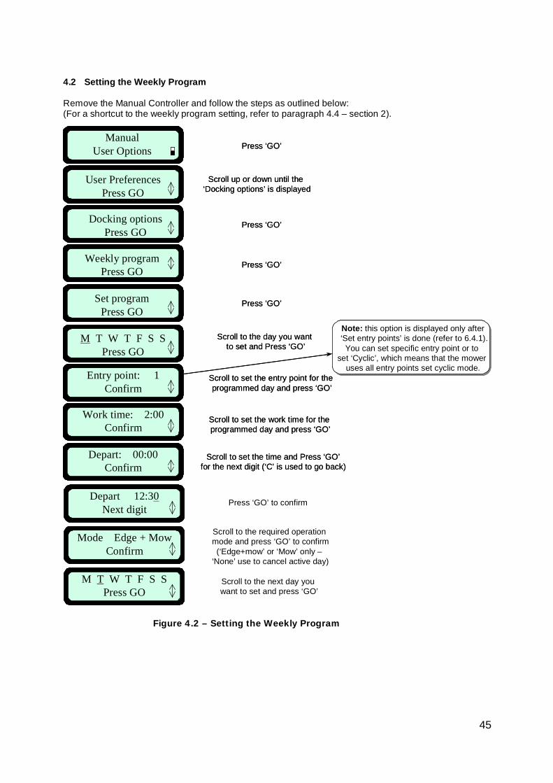
45
Depart 12:30Next digit
Mode Edge + MowConfirm
M T W T F S SPress GO
Press ‘GO’ to confirm
Scroll to the required operation mode and press ‘GO’ to confirm(‘Edge+mow’ or ‘Mow’ only –
‘None’ use to cancel active day)
Scroll to the next day you want to set and press ‘GO’
Entry point: 1Confirm
ManualUser Options
User PreferencesPress GO
Weekly programPress GO
Set programPress GO
M T W T F S SPress GO
Docking optionsPress GO
Work time: 2:00Confirm
Scroll to set the work time for the programmed day and press ‘GO’
Press ‘GO’
Scroll up or down until the ‘Docking options’ is displayed
Press ‘GO’
Scroll to the day you want to set and Press ‘GO’
Press ‘GO’
Press ‘GO’
Scroll to set the time and Press ‘GO’for the next digit (‘C’ is used to go back)
Scroll to set the entry point for the programmed day and press ‘GO’
Depart: 00:00Confirm
Note: this option is displayed only after‘Set entry points’ is done (refer to 6.4.1).
You can set specific entry point or to set ‘Cyclic’, which means that the mower
uses all entry points set cyclic mode.Entry point: 1
Confirm
ManualUser Options
User PreferencesPress GO
Weekly programPress GO
Set programPress GO
M T W T F S SPress GO
Docking optionsPress GO
Work time: 2:00Confirm
Scroll to set the work time for the programmed day and press ‘GO’
Press ‘GO’
Scroll up or down until the ‘Docking options’ is displayed
Press ‘GO’
Scroll to the day you want to set and Press ‘GO’
Press ‘GO’
Press ‘GO’
Scroll to set the time and Press ‘GO’for the next digit (‘C’ is used to go back)
Scroll to set the entry point for the programmed day and press ‘GO’
Depart: 00:00Confirm
Note: this option is displayed only after‘Set entry points’ is done (refer to 6.4.1).
You can set specific entry point or to set ‘Cyclic’, which means that the mower
uses all entry points set cyclic mode.
4.2 Setting the Weekly Program Remove the Manual Controller and follow the steps as outlined below: (For a shortcut to the weekly program setting, refer to paragraph 4.4 – section 2).
Figure 4.2 – Setting the Weekly Program
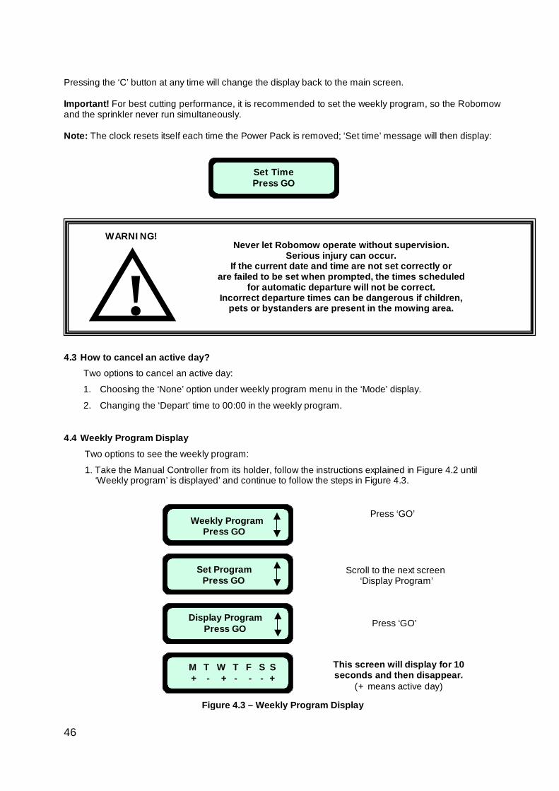
46
Pressing the ‘C’ button at any time will change the display back to the main screen. Important! For best cutting performance, it is recommended to set the weekly program, so the Robomow and the sprinkler never run simultaneously. Note: The clock resets itself each time the Power Pack is removed; ‘Set time’ message will then display:
4.3 How to cancel an active day?
Two options to cancel an active day:
1. Choosing the ‘None’ option under weekly program menu in the ‘Mode’ display.
2. Changing the ‘Depart’ time to 00:00 in the weekly program.
4.4 Weekly Program Display Two options to see the weekly program:
1. Take the Manual Controller from its holder, follow the instructions explained in Figure 4.2 until ‘Weekly program’ is displayed’ and continue to follow the steps in Figure 4.3.
Set Time Press GO
!WARNING!
Never let Robomow operate without supervision. Serious injury can occur.
If the current date and time are not set correctly or are failed to be set when prompted, the times scheduled
for automatic departure will not be correct. Incorrect departure times can be dangerous if children,
pets or bystanders are present in the mowing area.
Weekly Program Press GO
Set Program Press GO
Display Program Press GO
M T W T F S S + - + - - - +
Press ‘GO’
Press ‘GO’
Scroll to the next screen ‘Display Program’
This screen will display for 10 seconds and then disappear.
(+ means active day)
Figure 4.3 – Weekly Program Display
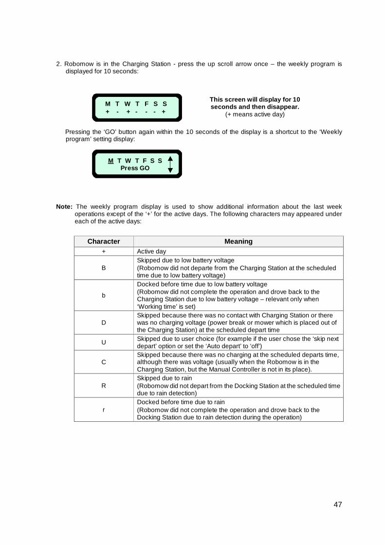
47
2. Robomow is in the Charging Station - press the up scroll arrow once – the weekly program is
displayed for 10 seconds:
Pressing the ‘GO’ button again within the 10 seconds of the display is a shortcut to the ‘Weekly program’ setting display:
Note: The weekly program display is used to show additional information about the last week operations except of the ‘+’ for the active days. The following characters may appeared under each of the active days:
Character Meaning
+ Active day
B Skipped due to low battery voltage (Robomow did not departe from the Charging Station at the scheduled time due to low battery voltage)
b
Docked before time due to low battery voltage (Robomow did not complete the operation and drove back to the Charging Station due to low battery voltage – relevant only when ‘Working time’ is set)
D Skipped because there was no contact with Charging Station or there was no charging voltage (power break or mower which is placed out of the Charging Station) at the scheduled depart time
U Skipped due to user choice (for example if the user chose the ‘skip next depart’ option or set the ‘Auto depart’ to ‘off’)
C Skipped because there was no charging at the scheduled departs time, although there was voltage (usually when the Robomow is in the Charging Station, but the Manual Controller is not in its place).
R Skipped due to rain (Robomow did not depart from the Docking Station at the scheduled time due to rain detection)
r Docked before time due to rain (Robomow did not complete the operation and drove back to the Docking Station due to rain detection during the operation)
M T W T F S S + - + - - - +
This screen will display for 10 seconds and then disappear.
(+ means active day)
T W T F S SM Press GO
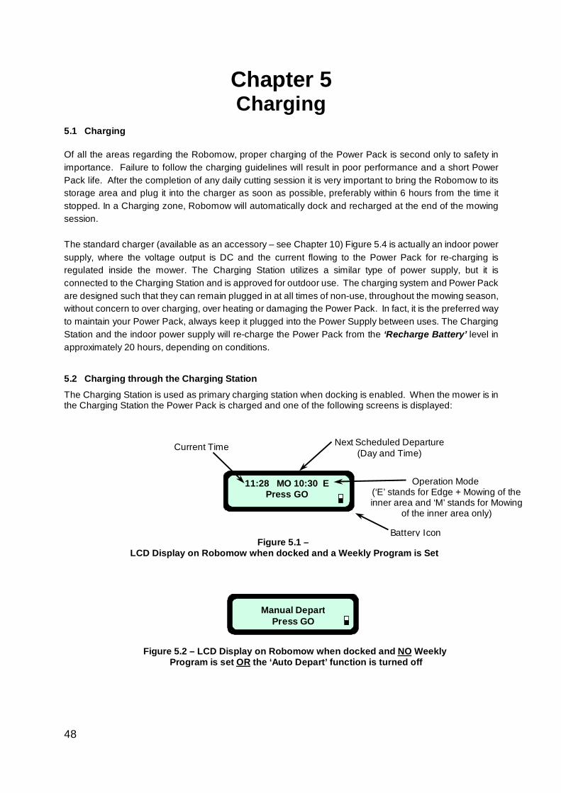
48
Chapter 5 Charging
5.1 Charging Of all the areas regarding the Robomow, proper charging of the Power Pack is second only to safety in importance. Failure to follow the charging guidelines will result in poor performance and a short Power Pack life. After the completion of any daily cutting session it is very important to bring the Robomow to its storage area and plug it into the charger as soon as possible, preferably within 6 hours from the time it stopped. In a Charging zone, Robomow will automatically dock and recharged at the end of the mowing session.
The standard charger (available as an accessory – see Chapter 10) Figure 5.4 is actually an indoor power supply, where the voltage output is DC and the current flowing to the Power Pack for re-charging is regulated inside the mower. The Charging Station utilizes a similar type of power supply, but it is connected to the Charging Station and is approved for outdoor use. The charging system and Power Pack are designed such that they can remain plugged in at all times of non-use, throughout the mowing season, without concern to over charging, over heating or damaging the Power Pack. In fact, it is the preferred way to maintain your Power Pack, always keep it plugged into the Power Supply between uses. The Charging Station and the indoor power supply will re-charge the Power Pack from the ‘Recharge Battery’ level in approximately 20 hours, depending on conditions.
5.2 Charging through the Charging Station The Charging Station is used as primary charging station when docking is enabled. When the mower is in the Charging Station the Power Pack is charged and one of the following screens is displayed:
11:28 MO 10:30 E Press GO
Current Time Next Scheduled Departure(Day and Time)
Operation Mode (‘E’ stands for Edge + Mowing of the inner area and ‘M’ stands for Mowing
of the inner area only) )
Battery Icon Figure 5.1 –
LCD Display on Robomow when docked and a Weekly Program is Set
Manual Depart Press GO
ly WeekNO LCD Display on Robomow when docked and –.2 5Figure the ‘Auto Depart’ function is turned offOR Program is set
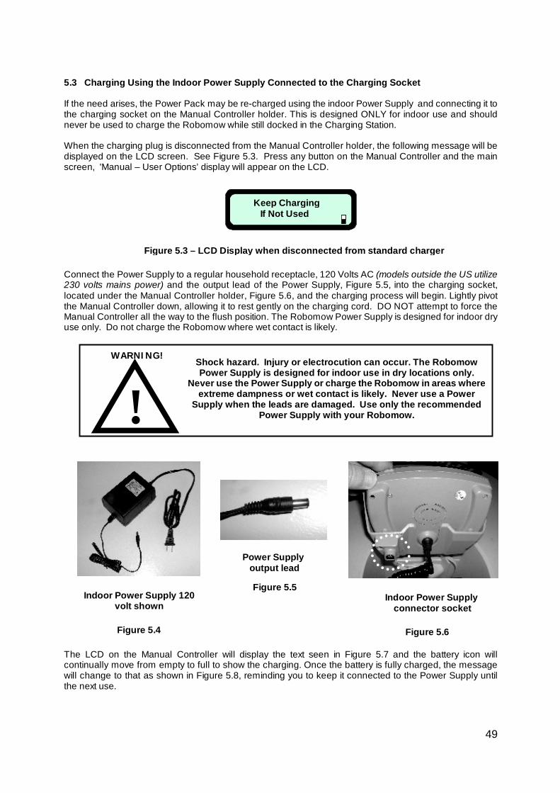
49
5.3 Charging Using the Indoor Power Supply Connected to the Charging Socket
If the need arises, the Power Pack may be re-charged using the indoor Power Supply and connecting it to the charging socket on the Manual Controller holder. This is designed ONLY for indoor use and should never be used to charge the Robomow while still docked in the Charging Station. When the charging plug is disconnected from the Manual Controller holder, the following message will be displayed on the LCD screen. See Figure 5.3. Press any button on the Manual Controller and the main screen, 'Manual – User Options’ display will appear on the LCD.
Connect the Power Supply to a regular household receptacle, 120 Volts AC (models outside the US utilize 230 volts mains power) and the output lead of the Power Supply, Figure 5.5, into the charging socket, located under the Manual Controller holder, Figure 5.6, and the charging process will begin. Lightly pivot the Manual Controller down, allowing it to rest gently on the charging cord. DO NOT attempt to force the Manual Controller all the way to the flush position. The Robomow Power Supply is designed for indoor dry use only. Do not charge the Robomow where wet contact is likely.
The LCD on the Manual Controller will display the text seen in Figure 5.7 and the battery icon will continually move from empty to full to show the charging. Once the battery is fully charged, the message will change to that as shown in Figure 5.8, reminding you to keep it connected to the Power Supply until the next use.
Keep Charging If Not Used
Figure 5.3 – LCD Display when disconnected from standard charger
Indoor Power Supply 120 volt shown
Figure 5.4
Power Supply output lead
Figure 5.5 Indoor Power Supply
connector socket
Figure 5.6
! Shock hazard. Injury or electrocution can occur. The Robomow Power Supply is designed for indoor use in dry locations only.
Never use the Power Supply or charge the Robomow in areas where extreme dampness or wet contact is likely. Never use a Power
Supply when the leads are damaged. Use only the recommended Power Supply with your Robomow.
WARNING!
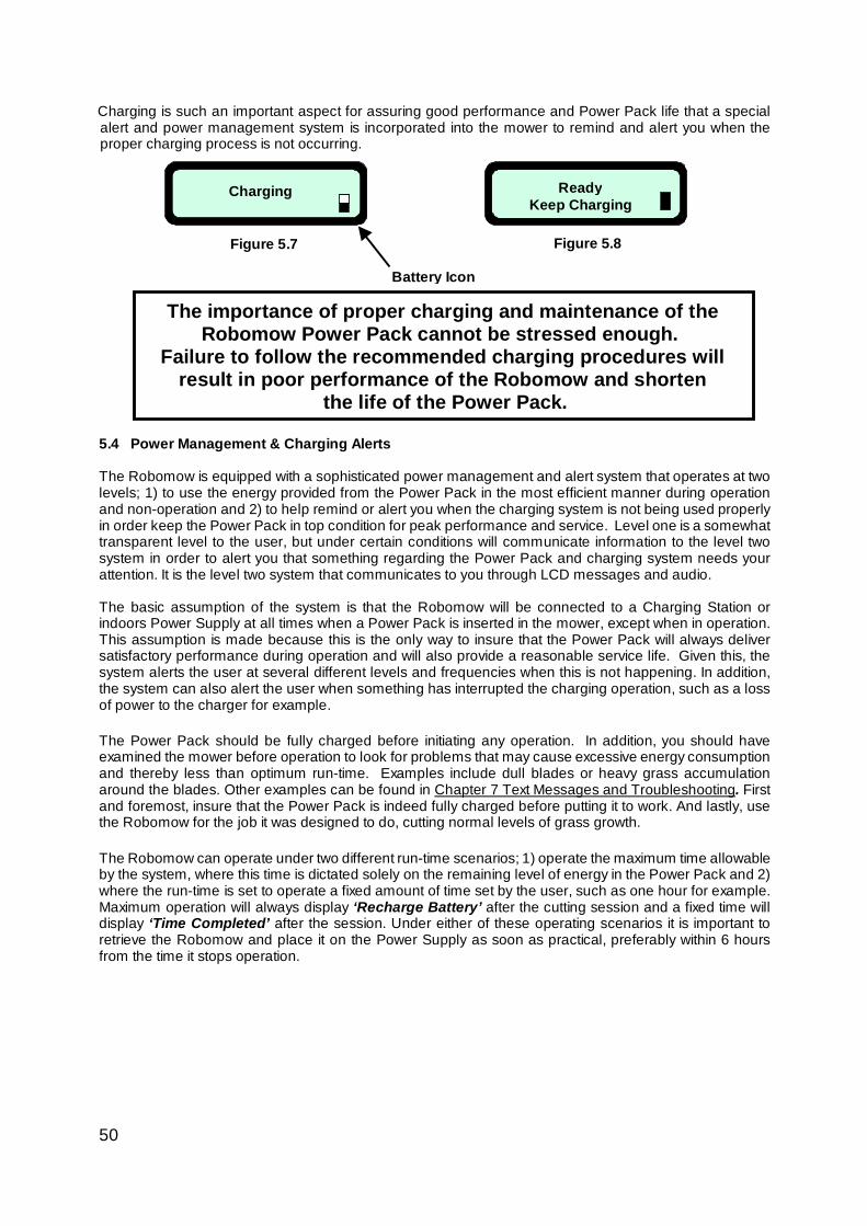
50
Charging is such an important aspect for assuring good performance and Power Pack life that a special alert and power management system is incorporated into the mower to remind and alert you when the proper charging process is not occurring.
5.4 Power Management & Charging Alerts
The Robomow is equipped with a sophisticated power management and alert system that operates at two levels; 1) to use the energy provided from the Power Pack in the most efficient manner during operation and non-operation and 2) to help remind or alert you when the charging system is not being used properly in order keep the Power Pack in top condition for peak performance and service. Level one is a somewhat transparent level to the user, but under certain conditions will communicate information to the level two system in order to alert you that something regarding the Power Pack and charging system needs your attention. It is the level two system that communicates to you through LCD messages and audio.
The basic assumption of the system is that the Robomow will be connected to a Charging Station or indoors Power Supply at all times when a Power Pack is inserted in the mower, except when in operation. This assumption is made because this is the only way to insure that the Power Pack will always deliver satisfactory performance during operation and will also provide a reasonable service life. Given this, the system alerts the user at several different levels and frequencies when this is not happening. In addition, the system can also alert the user when something has interrupted the charging operation, such as a loss of power to the charger for example.
The Power Pack should be fully charged before initiating any operation. In addition, you should have examined the mower before operation to look for problems that may cause excessive energy consumption and thereby less than optimum run-time. Examples include dull blades or heavy grass accumulation around the blades. Other examples can be found in Chapter 7 Text Messages and Troubleshooting. First and foremost, insure that the Power Pack is indeed fully charged before putting it to work. And lastly, use the Robomow for the job it was designed to do, cutting normal levels of grass growth. The Robomow can operate under two different run-time scenarios; 1) operate the maximum time allowable by the system, where this time is dictated solely on the remaining level of energy in the Power Pack and 2) where the run-time is set to operate a fixed amount of time set by the user, such as one hour for example. Maximum operation will always display ‘Recharge Battery’ after the cutting session and a fixed time will display ‘Time Completed’ after the session. Under either of these operating scenarios it is important to retrieve the Robomow and place it on the Power Supply as soon as practical, preferably within 6 hours from the time it stops operation.
Figure 5.8
Ready Keep Charging
Figure 5.7
Charging
Battery Icon
The importance of proper charging and maintenance of the Robomow Power Pack cannot be stressed enough.
Failure to follow the recommended charging procedures will result in poor performance of the Robomow and shorten
the life of the Power Pack.
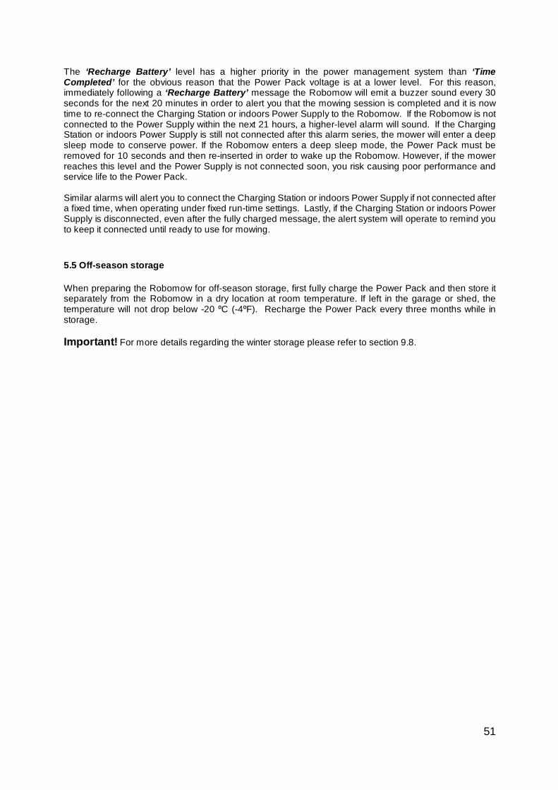
51
The ‘Recharge Battery’ level has a higher priority in the power management system than ‘Time Completed’ for the obvious reason that the Power Pack voltage is at a lower level. For this reason, immediately following a ‘Recharge Battery’ message the Robomow will emit a buzzer sound every 30 seconds for the next 20 minutes in order to alert you that the mowing session is completed and it is now time to re-connect the Charging Station or indoors Power Supply to the Robomow. If the Robomow is not connected to the Power Supply within the next 21 hours, a higher-level alarm will sound. If the Charging Station or indoors Power Supply is still not connected after this alarm series, the mower will enter a deep sleep mode to conserve power. If the Robomow enters a deep sleep mode, the Power Pack must be removed for 10 seconds and then re-inserted in order to wake up the Robomow. However, if the mower reaches this level and the Power Supply is not connected soon, you risk causing poor performance and service life to the Power Pack.
Similar alarms will alert you to connect the Charging Station or indoors Power Supply if not connected after a fixed time, when operating under fixed run-time settings. Lastly, if the Charging Station or indoors Power Supply is disconnected, even after the fully charged message, the alert system will operate to remind you to keep it connected until ready to use for mowing.
5.5 Off-season storage
When preparing the Robomow for off-season storage, first fully charge the Power Pack and then store it separately from the Robomow in a dry location at room temperature. If left in the garage or shed, the temperature will not drop below -20 ºC (-4ºF). Recharge the Power Pack every three months while in storage. Important! For more details regarding the winter storage please refer to section 9.8.
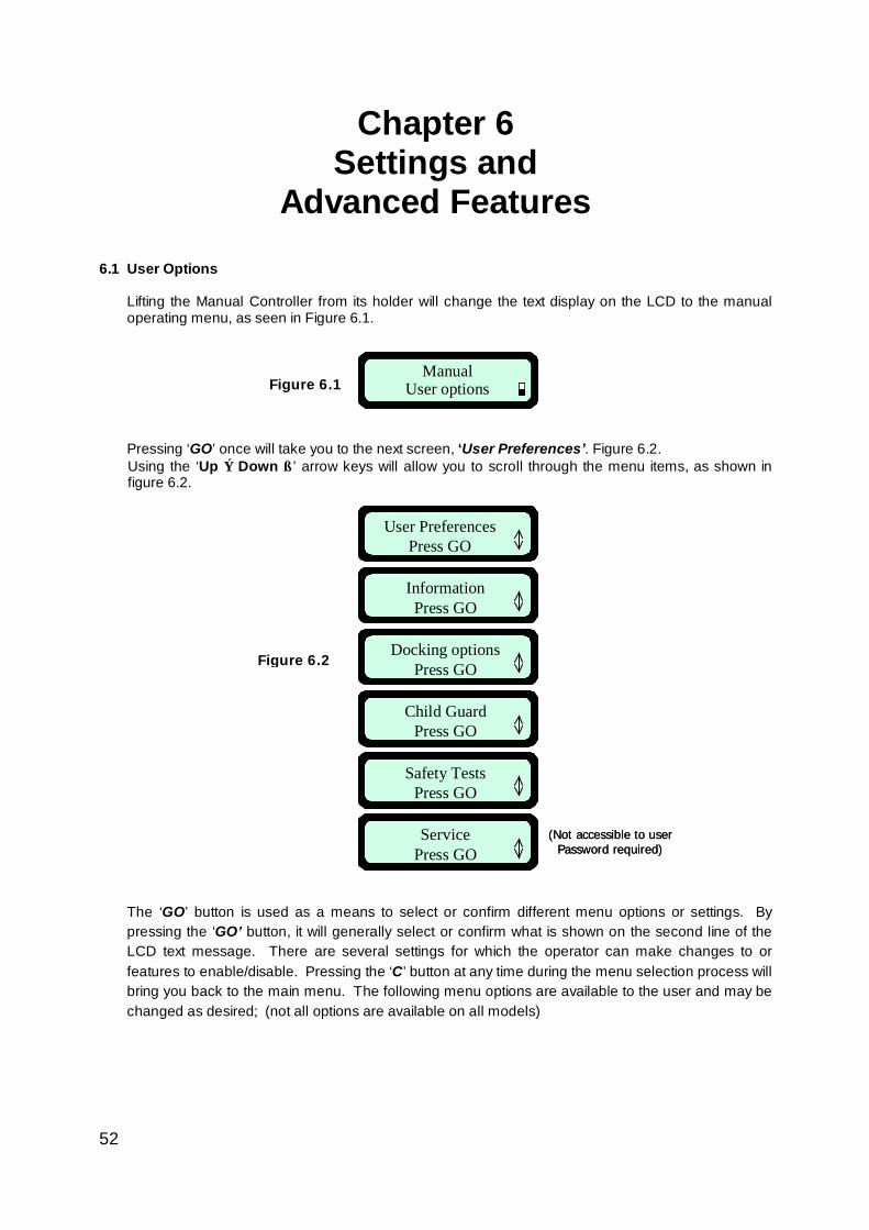
52
ManualUser options
(Not accessible to user Password required)
InformationPress GO
User PreferencesPress GO
Child GuardPress GO
Docking optionsPress GO
ServicePress GO
Safety TestsPress GO
(Not accessible to user Password required)
InformationPress GO
User PreferencesPress GO
Child GuardPress GO
Docking optionsPress GO
ServicePress GO
Safety TestsPress GO
InformationPress GO
User PreferencesPress GO
Child GuardPress GO
Docking optionsPress GO
ServicePress GO
Safety TestsPress GO
Chapter 6 Settings and
Advanced Features
6.1 User Options
Lifting the Manual Controller from its holder will change the text display on the LCD to the manual operating menu, as seen in Figure 6.1. Pressing ‘GO’ once will take you to the next screen, ‘User Preferences’. Figure 6.2. Using the ‘Up ⇑ Down ⇓’ arrow keys will allow you to scroll through the menu items, as shown in figure 6.2.
The ‘GO’ button is used as a means to select or confirm different menu options or settings. By pressing the ‘GO’ button, it will generally select or confirm what is shown on the second line of the LCD text message. There are several settings for which the operator can make changes to or features to enable/disable. Pressing the ‘C’ button at any time during the menu selection process will bring you back to the main menu. The following menu options are available to the user and may be changed as desired; (not all options are available on all models)
Figure 6.1
Figure 6.2
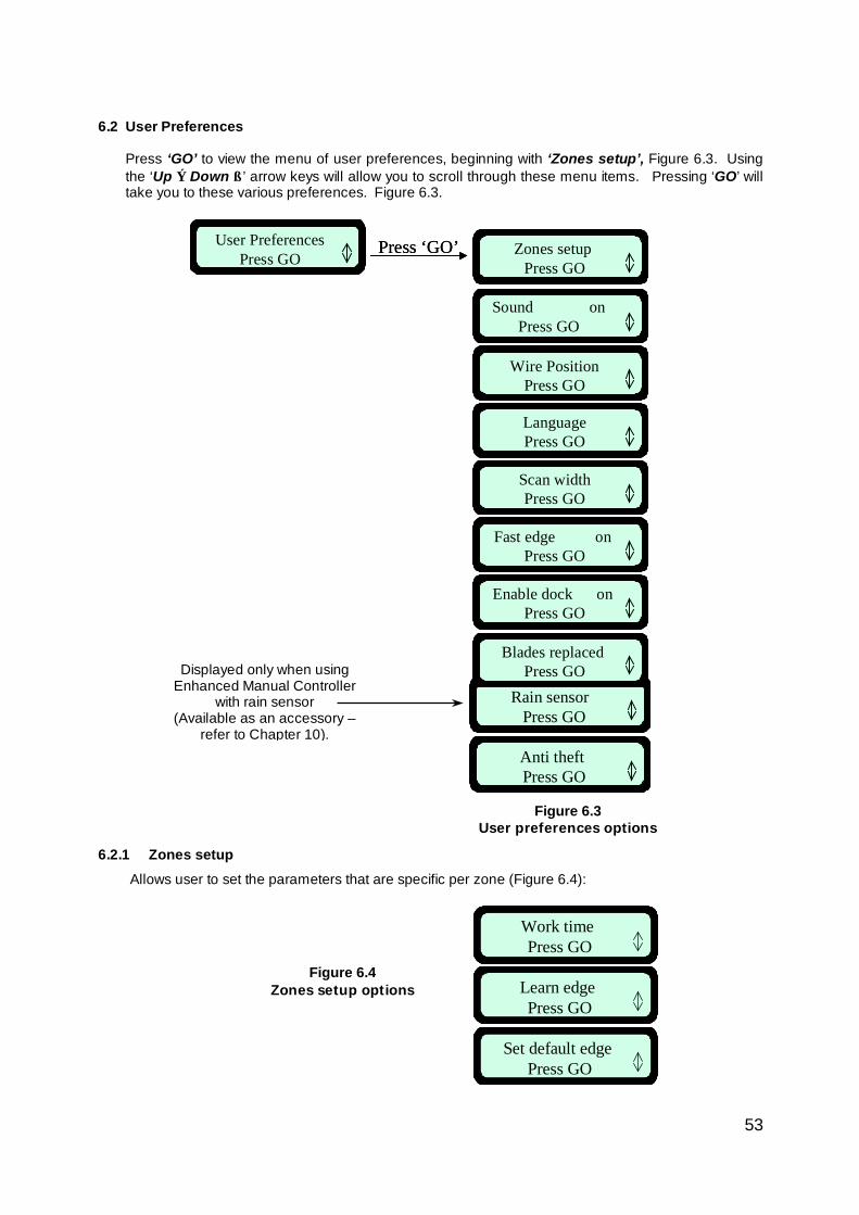
53
Rain sensor Press GO
Anti theft Press GO
Rain sensor Press GO
Anti theft Press GO
Work time Press GO
Learn edge Press GO
Set default edge Press GO
Work time Press GO
Work time Press GO
Learn edge Press GO
Learn edge Press GO
Set default edge Press GO
Set default edge Press GO
User PreferencesPress GO
Press ‘GO’
Sound onPress GO
Wire PositionPress GO
LanguagePress GO
Scan widthPress GO
Blades replaced Press GO
Zones setup Press GO
Fast edge on Press GO
Enable dock on Press GO
User PreferencesPress GO
Press ‘GO’
Sound onPress GO
Wire PositionPress GO
LanguagePress GO
Scan widthPress GO
Blades replaced Press GO
Zones setup Press GO
Zones setup Press GO
Fast edge on Press GO
Fast edge on Press GO
Enable dock on Press GO
Enable dock on Press GO
6.2 User Preferences
Press ‘GO’ to view the menu of user preferences, beginning with ‘Zones setup’, Figure 6.3. Using the ‘Up ⇑ Down ⇓’ arrow keys will allow you to scroll through these menu items. Pressing ‘GO’ will take you to these various preferences. Figure 6.3.
6.2.1 Zones setup
Allows user to set the parameters that are specific per zone (Figure 6.4):
Figure 6.3 User preferences options
Figure 6.4 Zones setup options
Displayed only when using Enhanced Manual Controller
with rain sensor (Available as an accessory –
refer to Chapter 10).
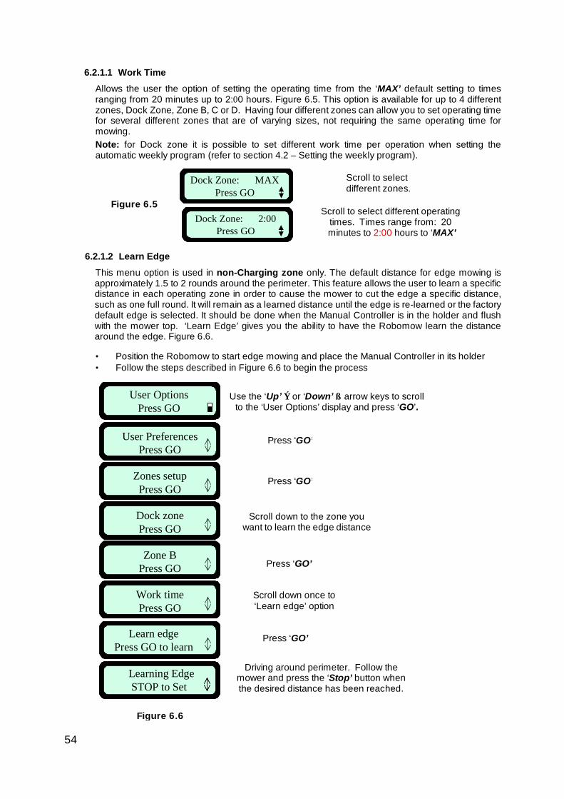
54
Dock Zone: MAX Press GO
Dock Zone: 2:00 Press GO
Learning EdgeSTOP to Set
User OptionsPress GO
User PreferencesPress GO
Zones setupPress GO
Dock zonePress GO
Zone BPress GO
Work timePress GO
Learn edgePress GO to learn
Learning EdgeSTOP to SetLearning EdgeSTOP to Set
User OptionsPress GO
User PreferencesPress GO
Zones setupPress GO
Dock zonePress GO
Zone BPress GO
Work timePress GO
Learn edgePress GO to learn
6.2.1.1 Work Time Allows the user the option of setting the operating time from the ‘MAX’ default setting to times ranging from 20 minutes up to 2:00 hours. Figure 6.5. This option is available for up to 4 different zones, Dock Zone, Zone B, C or D. Having four different zones can allow you to set operating time for several different zones that are of varying sizes, not requiring the same operating time for mowing. Note: for Dock zone it is possible to set different work time per operation when setting the automatic weekly program (refer to section 4.2 – Setting the weekly program).
6.2.1.2 Learn Edge This menu option is used in non-Charging zone only. The default distance for edge mowing is approximately 1.5 to 2 rounds around the perimeter. This feature allows the user to learn a specific distance in each operating zone in order to cause the mower to cut the edge a specific distance, such as one full round. It will remain as a learned distance until the edge is re-learned or the factory default edge is selected. It should be done when the Manual Controller is in the holder and flush with the mower top. ‘Learn Edge’ gives you the ability to have the Robomow learn the distance around the edge. Figure 6.6. • Position the Robomow to start edge mowing and place the Manual Controller in its holder • Follow the steps described in Figure 6.6 to begin the process
Scroll to select different zones.
Scroll to select different operating times. Times range from: 20 minutes to 2:00 hours to ‘MAX’
Figure 6.5
Scroll down once to ‘Learn edge’ option
Press ‘GO’
Driving around perimeter. Follow the mower and press the ‘Stop’ button when the desired distance has been reached.
Use the ‘Up’ ⇑ or ‘Down’ ⇓ arrow keys to scroll to the ‘User Options’ display and press ‘GO’.
Press ‘GO’
Figure 6.6
Press ‘GO’
Scroll down to the zone you want to learn the edge distance
Press ‘GO’
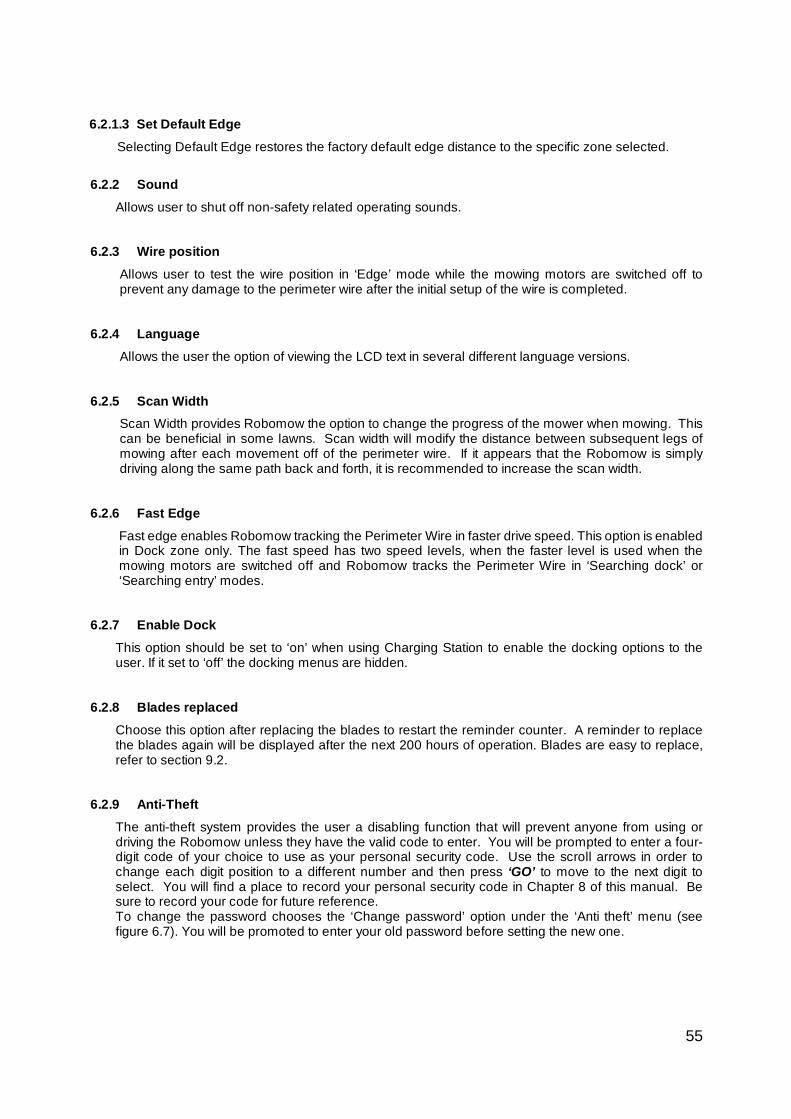
55
6.2.1.3 Set Default Edge
Selecting Default Edge restores the factory default edge distance to the specific zone selected. 6.2.2 Sound
Allows user to shut off non-safety related operating sounds.
6.2.3 Wire position Allows user to test the wire position in ‘Edge’ mode while the mowing motors are switched off to prevent any damage to the perimeter wire after the initial setup of the wire is completed.
6.2.4 Language
Allows the user the option of viewing the LCD text in several different language versions. 6.2.5 Scan Width
Scan Width provides Robomow the option to change the progress of the mower when mowing. This can be beneficial in some lawns. Scan width will modify the distance between subsequent legs of mowing after each movement off of the perimeter wire. If it appears that the Robomow is simply driving along the same path back and forth, it is recommended to increase the scan width.
6.2.6 Fast Edge Fast edge enables Robomow tracking the Perimeter Wire in faster drive speed. This option is enabled in Dock zone only. The fast speed has two speed levels, when the faster level is used when the mowing motors are switched off and Robomow tracks the Perimeter Wire in ‘Searching dock’ or ‘Searching entry’ modes.
6.2.7 Enable Dock
This option should be set to ‘on’ when using Charging Station to enable the docking options to the user. If it set to ‘off’ the docking menus are hidden.
6.2.8 Blades replaced Choose this option after replacing the blades to restart the reminder counter. A reminder to replace the blades again will be displayed after the next 200 hours of operation. Blades are easy to replace, refer to section 9.2.
6.2.9 Anti-Theft
The anti-theft system provides the user a disabling function that will prevent anyone from using or driving the Robomow unless they have the valid code to enter. You will be prompted to enter a four-digit code of your choice to use as your personal security code. Use the scroll arrows in order to change each digit position to a different number and then press ‘GO’ to move to the next digit to select. You will find a place to record your personal security code in Chapter 8 of this manual. Be sure to record your code for future reference. To change the password chooses the ‘Change password’ option under the ‘Anti theft’ menu (see figure 6.7). You will be promoted to enter your old password before setting the new one.
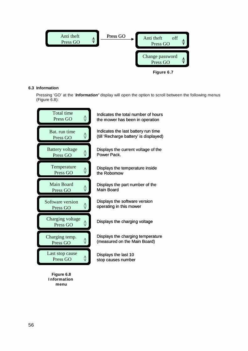
56
Change password Press GO
Anti theft Press GO
Press GO Anti theft offPress GO
Change password Press GO
Anti theft Press GO
Press GO Anti theft offPress GO
Charging voltagePress GO
Total timePress GO
Bat. run timePress GO
TemperaturePress GO
Main BoardPress GO
Software versionPress GO
Battery voltagePress GO
Last stop causePress GO
Charging temp.Press GO
Indicates the total number of hours the mower has been in operation
Indicates the last battery run time(till ‘Recharge battery’ is displayed)
Displays the current voltage of the Power Pack.
Displays the temperature insidethe Robomow
Displays the part number of theMain Board
Displays the software version operating in this mower
Displays the charging voltage
Displays the charging temperature (measured on the Main Board)
Displays the last 10 stop causes number
Charging voltagePress GO
Total timePress GO
Bat. run timePress GO
TemperaturePress GO
Main BoardPress GO
Software versionPress GO
Battery voltagePress GO
Last stop causePress GO
Charging temp.Press GO
Charging voltagePress GO
Total timePress GO
Bat. run timePress GO
TemperaturePress GO
Main BoardPress GO
Software versionPress GO
Battery voltagePress GO
Last stop causePress GO
Charging temp.Press GO
Indicates the total number of hours the mower has been in operation
Indicates the last battery run time(till ‘Recharge battery’ is displayed)
Displays the current voltage of the Power Pack.
Displays the temperature insidethe Robomow
Displays the part number of theMain Board
Displays the software version operating in this mower
Displays the charging voltage
Displays the charging temperature (measured on the Main Board)
Displays the last 10 stop causes number
6.3 Information Pressing ‘GO’ at the ‘Information’ display will open the option to scroll between the following menus (Figure 6.8):
Figure 6.7
Figure 6.8 Information
menu
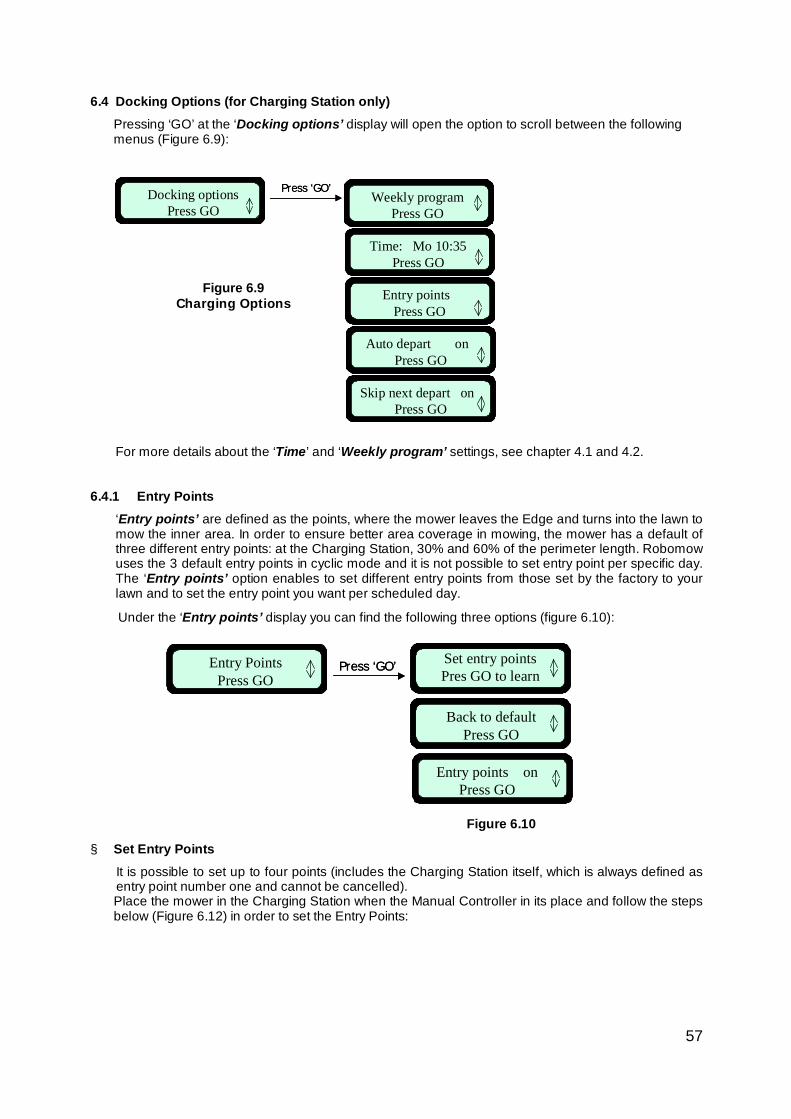
57
Set entry pointsPres GO to learn
Back to defaultPress GO
Entry points onPress GO
Entry PointsPress GO
Press ‘GO’Press ‘GO’
Weekly programPress GO
Time: Mo 10:35Press GO
Press ‘GO’Docking optionsPress GO
Entry points Press GO
Auto depart on Press GO
Skip next depart on Press GO
Weekly programPress GO
Time: Mo 10:35Press GO
Press ‘GO’Docking optionsPress GO
Entry points Press GO
Auto depart on Press GO
Skip next depart on Press GO
6.4 Docking Options (for Charging Station only) Pressing ‘GO’ at the ‘Docking options’ display will open the option to scroll between the following menus (Figure 6.9):
For more details about the ‘Time’ and ‘Weekly program’ settings, see chapter 4.1 and 4.2.
6.4.1 Entry Points
‘Entry points’ are defined as the points, where the mower leaves the Edge and turns into the lawn to mow the inner area. In order to ensure better area coverage in mowing, the mower has a default of three different entry points: at the Charging Station, 30% and 60% of the perimeter length. Robomow uses the 3 default entry points in cyclic mode and it is not possible to set entry point per specific day. The ‘Entry points’ option enables to set different entry points from those set by the factory to your lawn and to set the entry point you want per scheduled day.
Under the ‘Entry points’ display you can find the following three options (figure 6.10):
§ Set Entry Points It is possible to set up to four points (includes the Charging Station itself, which is always defined as entry point number one and cannot be cancelled). Place the mower in the Charging Station when the Manual Controller in its place and follow the steps below (Figure 6.12) in order to set the Entry Points:
Figure 6.9 Charging Options
Figure 6.10
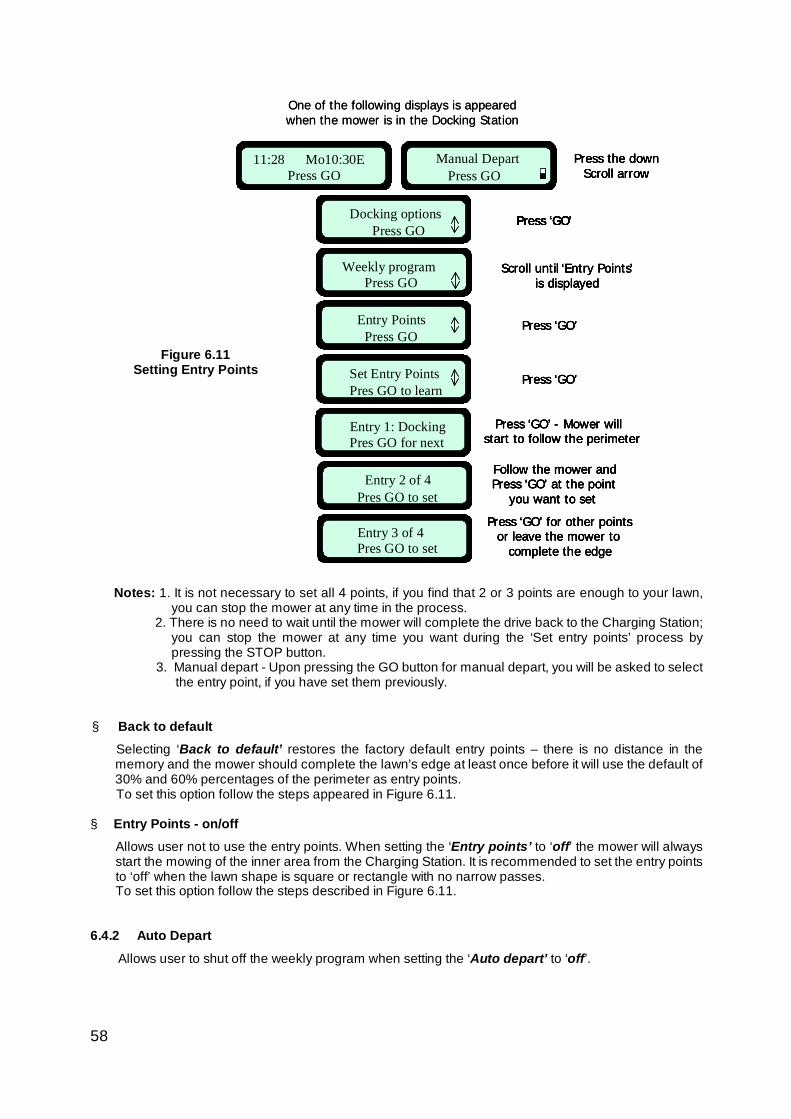
58
Press ‘GO’Docking optionsPress GO
Scroll until ‘Entry Points’is displayed
Time: Mo 11:55Press GO
Entry PointsPress GO
Press ‘GO’
Set Entry PointsPres GO to learn
Press ‘GO’
Manual Depart Press GO
Press the downScroll arrow
Entry 1: DockingPres GO for next
Press ‘GO’ - Mower will start to follow the perimeter
Entry 2 of 4Pres GO to set
Follow the mower and Press ‘GO’ at the point
you want to set
Entry 3 of 4Pres GO to set
Press ‘GO’ for other pointsor leave the mower to
complete the edge
11:28 Mo10:30EPress GO
One of the following displays is appeared when the mower is in the Docking Station
Press ‘GO’Docking optionsPress GO
Press ‘GO’Docking optionsPress GO
Scroll until ‘Entry Points’is displayed
Weekly programPress GO
Entry PointsPress GO
Press ‘GO’
Set Entry PointsPres GO to learn
Press ‘GO’
Manual Depart Press GO
Press the downScroll arrow
Entry 1: DockingPres GO for next
Press ‘GO’ - Mower will start to follow the perimeter
Entry 2 of 4Pres GO to set
Follow the mower and Press ‘GO’ at the point
you want to set
Entry 3 of 4Pres GO to set
Press ‘GO’ for other pointsor leave the mower to
complete the edge
11:28 Mo10:30EPress GO
11:28 Mo10:30EPress GO
Press ‘GO’Docking optionsPress GO
Press ‘GO’Docking optionsPress GO
Scroll until ‘Entry Points’is displayed
Time: Mo 11:55Press GO
Entry PointsPress GO
Press ‘GO’
Set Entry PointsPres GO to learn
Press ‘GO’
Manual Depart Press GO
Press the downScroll arrow
Entry 1: DockingPres GO for next
Press ‘GO’ - Mower will start to follow the perimeter
Entry 2 of 4Pres GO to set
Follow the mower and Press ‘GO’ at the point
you want to set
Entry 3 of 4Pres GO to set
Press ‘GO’ for other pointsor leave the mower to
complete the edge
11:28 Mo10:30EPress GO
11:28 Mo10:30EPress GO
One of the following displays is appeared when the mower is in the Docking Station
Press ‘GO’Docking optionsPress GO
Press ‘GO’Docking optionsPress GO
Scroll until ‘Entry Points’is displayed
Weekly programPress GO
Entry PointsPress GO
Press ‘GO’
Set Entry PointsPres GO to learn
Press ‘GO’
Manual Depart Press GO
Press the downScroll arrow
Entry 1: DockingPres GO for next
Press ‘GO’ - Mower will start to follow the perimeter
Entry 2 of 4Pres GO to set
Follow the mower and Press ‘GO’ at the point
you want to set
Entry 3 of 4Pres GO to set
Press ‘GO’ for other pointsor leave the mower to
complete the edge
11:28 Mo10:30EPress GO
11:28 Mo10:30EPress GO
Notes: 1. It is not necessary to set all 4 points, if you find that 2 or 3 points are enough to your lawn, you can stop the mower at any time in the process.
2. There is no need to wait until the mower will complete the drive back to the Charging Station; you can stop the mower at any time you want during the ‘Set entry points’ process by pressing the STOP button.
3. Manual depart - Upon pressing the GO button for manual depart, you will be asked to select the entry point, if you have set them previously.
§ Back to default
Selecting ‘Back to default’ restores the factory default entry points – there is no distance in the memory and the mower should complete the lawn’s edge at least once before it will use the default of 30% and 60% percentages of the perimeter as entry points. To set this option follow the steps appeared in Figure 6.11.
§ Entry Points - on/off Allows user not to use the entry points. When setting the ‘Entry points’ to ‘off’ the mower will always start the mowing of the inner area from the Charging Station. It is recommended to set the entry points to ‘off’ when the lawn shape is square or rectangle with no narrow passes. To set this option follow the steps described in Figure 6.11.
6.4.2 Auto Depart
Allows user to shut off the weekly program when setting the ‘Auto depart’ to ‘off’.
Figure 6.11 Setting Entry Points
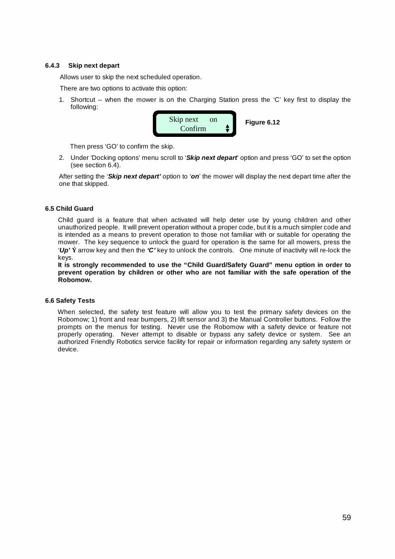
59
Skip next on Confirm
6.4.3 Skip next depart
Allows user to skip the next scheduled operation.
There are two options to activate this option:
1. Shortcut – when the mower is on the Charging Station press the ‘C’ key first to display the following:
Then press ‘GO’ to confirm the skip.
2. Under ‘Docking options’ menu scroll to ‘Skip next depart’ option and press ‘GO’ to set the option (see section 6.4).
After setting the ‘Skip next depart’ option to ‘on’ the mower will display the next depart time after the one that skipped.
6.5 Child Guard
Child guard is a feature that when activated will help deter use by young children and other unauthorized people. It will prevent operation without a proper code, but it is a much simpler code and is intended as a means to prevent operation to those not familiar with or suitable for operating the mower. The key sequence to unlock the guard for operation is the same for all mowers, press the ‘Up’ ⇑ arrow key and then the ‘C’ key to unlock the controls. One minute of inactivity will re-lock the keys. It is strongly recommended to use the “Child Guard/Safety Guard” menu option in order to prevent operation by children or other who are not familiar with the safe operation of the Robomow.
6.6 Safety Tests When selected, the safety test feature will allow you to test the primary safety devices on the Robomow; 1) front and rear bumpers, 2) lift sensor and 3) the Manual Controller buttons. Follow the prompts on the menus for testing. Never use the Robomow with a safety device or feature not properly operating. Never attempt to disable or bypass any safety device or system. See an authorized Friendly Robotics service facility for repair or information regarding any safety system or device.
Figure 6.12
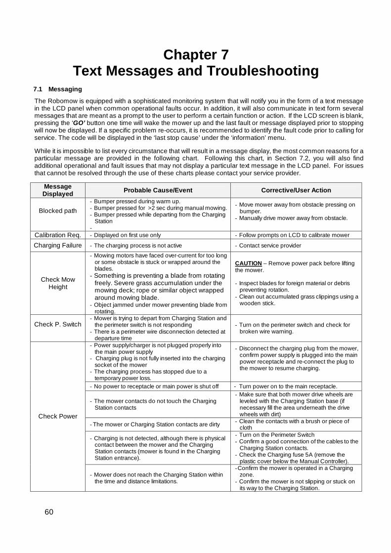
60
Chapter 7 Text Messages and Troubleshooting
7.1 Messaging
The Robomow is equipped with a sophisticated monitoring system that will notify you in the form of a text message in the LCD panel when common operational faults occur. In addition, it will also communicate in text form several messages that are meant as a prompt to the user to perform a certain function or action. If the LCD screen is blank, pressing the ‘GO’ button one time will wake the mower up and the last fault or message displayed prior to stopping will now be displayed. If a specific problem re-occurs, it is recommended to identify the fault code prior to calling for service. The code will be displayed in the ‘last stop cause’ under the ‘information’ menu. While it is impossible to list every circumstance that will result in a message display, the most common reasons for a particular message are provided in the following chart. Following this chart, in Section 7.2, you will also find additional operational and fault issues that may not display a particular text message in the LCD panel. For issues that cannot be resolved through the use of these charts please contact your service provider.
Message Displayed Probable Cause/Event Corrective/User Action
Blocked path
- Bumper pressed during warm up. - Bumper pressed for >2 sec during manual mowing. - Bumper pressed while departing from the Charging
Station -
- Move mower away from obstacle pressing on bumper.
- Manually drive mower away from obstacle.
Calibration Req. - Displayed on first use only - Follow prompts on LCD to calibrate mower
Charging Failure - The charging process is not active - Contact service provider
Check Mow Height
- Mowing motors have faced over-current for too long or some obstacle is stuck or wrapped around the blades.
- Something is preventing a blade from rotating freely. Severe grass accumulation under the mowing deck; rope or similar object wrapped around mowing blade.
- Object jammed under mower preventing blade from rotating.
CAUTION – Remove power pack before lifting the mower. - Inspect blades for foreign material or debris
preventing rotation. - Clean out accumulated grass clippings using a
wooden stick.
Check P. Switch
- Mower is trying to depart from Charging Station and the perimeter switch is not responding
- There is a perimeter wire disconnection detected at departure time
- Turn on the perimeter switch and check for broken wire warning.
- Power supply/charger is not plugged properly into the main power supply
- Charging plug is not fully inserted into the charging socket of the mower
- The charging process has stopped due to a temporary power loss.
- Disconnect the charging plug from the mower, confirm power supply is plugged into the main power receptacle and re-connect the plug to the mower to resume charging.
- No power to receptacle or main power is shut off - Turn power on to the main receptacle.
- The mower contacts do not touch the Charging Station contacts
- Make sure that both mower drive wheels are leveled with the Charging Station base (if necessary fill the area underneath the drive wheels with dirt)
- The mower or Charging Station contacts are dirty - Clean the contacts with a brush or piece of cloth
- Charging is not detected, although there is physical contact between the mower and the Charging Station contacts (mower is found in the Charging Station entrance).
- Turn on the Perimeter Switch - Confirm a good connection of the cables to the
Charging Station contacts. - Check the Charging fuse 5A (remove the
plastic cover below the Manual Controller).
Check Power
- Mower does not reach the Charging Station within the time and distance limitations.
- Confirm the mower is operated in a Charging zone.
- Confirm the mower is not slipping or stuck on its way to the Charging Station.
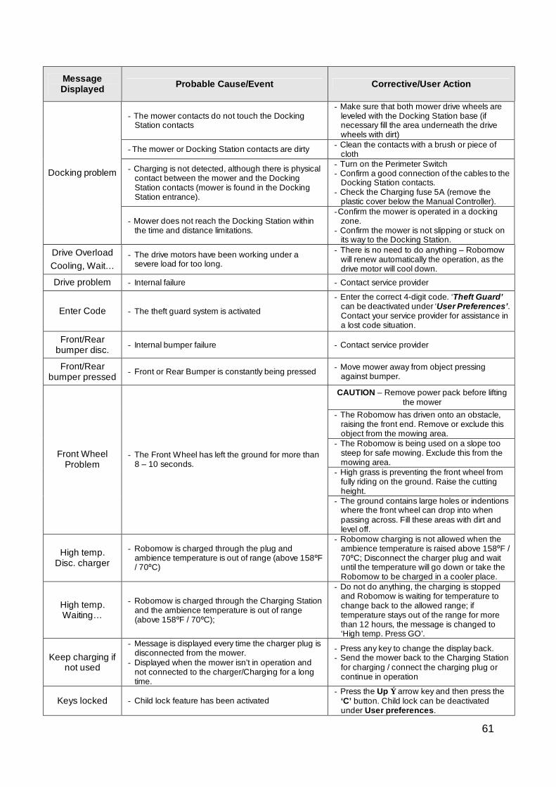
61
Message Displayed Probable Cause/Event Corrective/User Action
- The mower contacts do not touch the Docking Station contacts
- Make sure that both mower drive wheels are leveled with the Docking Station base (if necessary fill the area underneath the drive wheels with dirt)
- The mower or Docking Station contacts are dirty - Clean the contacts with a brush or piece of cloth
- Charging is not detected, although there is physical contact between the mower and the Docking Station contacts (mower is found in the Docking Station entrance).
- Turn on the Perimeter Switch - Confirm a good connection of the cables to the
Docking Station contacts. - Check the Charging fuse 5A (remove the
plastic cover below the Manual Controller).
Docking problem
- Mower does not reach the Docking Station within the time and distance limitations.
- Confirm the mower is operated in a docking zone.
- Confirm the mower is not slipping or stuck on its way to the Docking Station.
Drive Overload Cooling, Wait…
- The drive motors have been working under a severe load for too long.
- There is no need to do anything – Robomow will renew automatically the operation, as the drive motor will cool down.
Drive problem - Internal failure - Contact service provider
Enter Code - The theft guard system is activated
- Enter the correct 4-digit code. ‘Theft Guard’ can be deactivated under ‘User Preferences’. Contact your service provider for assistance in a lost code situation.
Front/Rear bumper disc. - Internal bumper failure - Contact service provider
Front/Rear bumper pressed - Front or Rear Bumper is constantly being pressed - Move mower away from object pressing
against bumper.
CAUTION – Remove power pack before lifting the mower
- The Robomow has driven onto an obstacle, raising the front end. Remove or exclude this object from the mowing area.
- The Robomow is being used on a slope too steep for safe mowing. Exclude this from the mowing area.
- High grass is preventing the front wheel from fully riding on the ground. Raise the cutting height.
Front Wheel Problem
- The Front Wheel has left the ground for more than 8 – 10 seconds.
- The ground contains large holes or indentions where the front wheel can drop into when passing across. Fill these areas with dirt and level off.
High temp. Disc. charger
- Robomow is charged through the plug and ambience temperature is out of range (above 158ºF / 70ºC)
- Robomow charging is not allowed when the ambience temperature is raised above 158ºF / 70ºC; Disconnect the charger plug and wait until the temperature will go down or take the Robomow to be charged in a cooler place.
High temp. Waiting…
- Robomow is charged through the Charging Station and the ambience temperature is out of range (above 158ºF / 70ºC);
- Do not do anything, the charging is stopped and Robomow is waiting for temperature to change back to the allowed range; if temperature stays out of the range for more than 12 hours, the message is changed to ‘High temp. Press GO’.
Keep charging if not used
- Message is displayed every time the charger plug is disconnected from the mower.
- Displayed when the mower isn’t in operation and not connected to the charger/Charging for a long time.
- Press any key to change the display back. - Send the mower back to the Charging Station
for charging / connect the charging plug or continue in operation
Keys locked - Child lock feature has been activated - Press the Up ⇑ arrow key and then press the
‘C’ button. Child lock can be deactivated under User preferences.
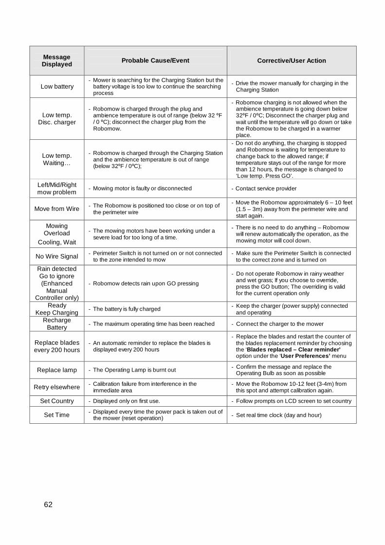
62
Message Displayed
Probable Cause/Event
Corrective/User Action
Low battery - Mower is searching for the Charging Station but the
battery voltage is too low to continue the searching process
- Drive the mower manually for charging in the Charging Station
Low temp. Disc. charger
- Robomow is charged through the plug and ambience temperature is out of range (below 32 ºF / 0 ºC); disconnect the charger plug from the Robomow.
- Robomow charging is not allowed when the ambience temperature is going down below 32ºF / 0ºC; Disconnect the charger plug and wait until the temperature will go down or take the Robomow to be charged in a warmer place.
Low temp. Waiting…
- Robomow is charged through the Charging Station and the ambience temperature is out of range (below 32ºF / 0ºC);
- Do not do anything, the charging is stopped and Robomow is waiting for temperature to change back to the allowed range; if temperature stays out of the range for more than 12 hours, the message is changed to ‘Low temp. Press GO’.
Left/Mid/Right mow problem - Mowing motor is faulty or disconnected - Contact service provider
Move from Wire - The Robomow is positioned too close or on top of the perimeter wire
- Move the Robomow approximately 6 – 10 feet (1.5 – 3m) away from the perimeter wire and start again.
Mowing Overload
Cooling, Wait
- The mowing motors have been working under a severe load for too long of a time.
- There is no need to do anything – Robomow will renew automatically the operation, as the mowing motor will cool down.
No Wire Signal - Perimeter Switch is not turned on or not connected to the zone intended to mow
- Make sure the Perimeter Switch is connected to the correct zone and is turned on
Rain detected Go to ignore (Enhanced
Manual Controller only)
- Robomow detects rain upon GO pressing
- Do not operate Robomow in rainy weather and wet grass; If you choose to override, press the GO button; The overriding is valid for the current operation only
Ready Keep Charging - The battery is fully charged - Keep the charger (power supply) connected
and operating Recharge
Battery - The maximum operating time has been reached - Connect the charger to the mower
Replace blades every 200 hours
- An automatic reminder to replace the blades is displayed every 200 hours
- Replace the blades and restart the counter of the blades replacement reminder by choosing the ‘Blades replaced – Clear reminder’ option under the ‘User Preferences’ menu
Replace lamp - The Operating Lamp is burnt out - Confirm the message and replace the Operating Bulb as soon as possible
Retry elsewhere - Calibration failure from interference in the immediate area
- Move the Robomow 10-12 feet (3-4m) from this spot and attempt calibration again.
Set Country - Displayed only on first use. - Follow prompts on LCD screen to set country
Set Time - Displayed every time the power pack is taken out of the mower (reset operation) - Set real time clock (day and hour)
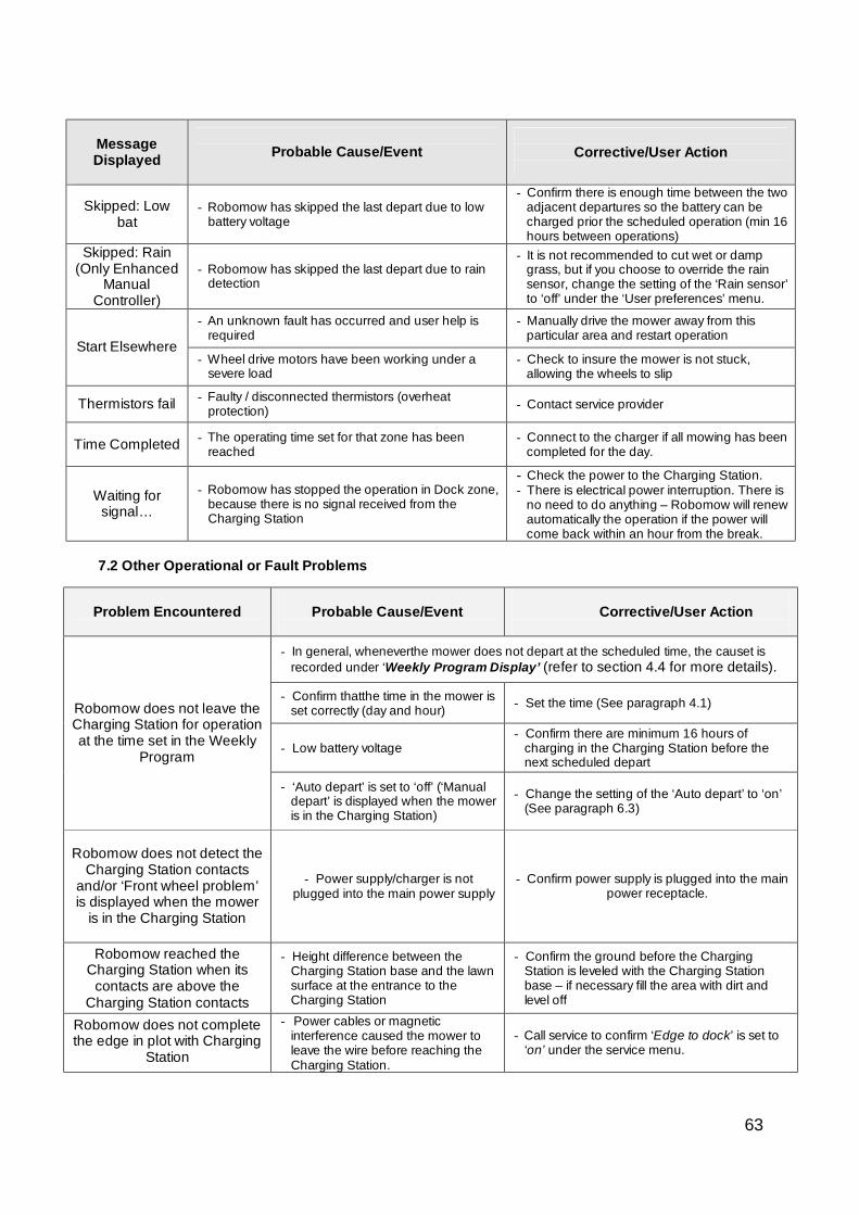
63
Message Displayed
Probable Cause/Event
Corrective/User Action
Skipped: Low bat
- Robomow has skipped the last depart due to low battery voltage
- Confirm there is enough time between the two adjacent departures so the battery can be charged prior the scheduled operation (min 16 hours between operations)
Skipped: Rain (Only Enhanced
Manual Controller)
- Robomow has skipped the last depart due to rain detection
- It is not recommended to cut wet or damp grass, but if you choose to override the rain sensor, change the setting of the ‘Rain sensor’ to ‘off’ under the ‘User preferences’ menu.
- An unknown fault has occurred and user help is required
- Manually drive the mower away from this particular area and restart operation
Start Elsewhere - Wheel drive motors have been working under a
severe load - Check to insure the mower is not stuck,
allowing the wheels to slip
Thermistors fail - Faulty / disconnected thermistors (overheat protection) - Contact service provider
Time Completed - The operating time set for that zone has been reached
- Connect to the charger if all mowing has been completed for the day.
Waiting for signal…
- Robomow has stopped the operation in Dock zone, because there is no signal received from the Charging Station
- Check the power to the Charging Station. - There is electrical power interruption. There is
no need to do anything – Robomow will renew automatically the operation if the power will come back within an hour from the break.
7.2 Other Operational or Fault Problems
Problem Encountered
Probable Cause/Event
Corrective/User Action
- In general, wheneverthe mower does not depart at the scheduled time, the causet is
recorded under ‘Weekly Program Display’ (refer to section 4.4 for more details).
- Confirm thatthe time in the mower is set correctly (day and hour) - Set the time (See paragraph 4.1)
- Low battery voltage - Confirm there are minimum 16 hours of
charging in the Charging Station before the next scheduled depart
Robomow does not leave the Charging Station for operation at the time set in the Weekly
Program
- ‘Auto depart’ is set to ‘off’ (‘Manual depart’ is displayed when the mower is in the Charging Station)
- Change the setting of the ‘Auto depart’ to ‘on’ (See paragraph 6.3)
Robomow does not detect the Charging Station contacts
and/or ‘Front wheel problem’ is displayed when the mower
is in the Charging Station
- Power supply/charger is not plugged into the main power supply
- Confirm power supply is plugged into the main power receptacle.
Robomow reached the Charging Station when its
contacts are above the Charging Station contacts
- Height difference between the Charging Station base and the lawn surface at the entrance to the Charging Station
- Confirm the ground before the Charging Station is leveled with the Charging Station base – if necessary fill the area with dirt and level off
Robomow does not complete the edge in plot with Charging
Station
- Power cables or magnetic interference caused the mower to leave the wire before reaching the Charging Station.
- Call service to confirm ‘Edge to dock’ is set to ‘on’ under the service menu.
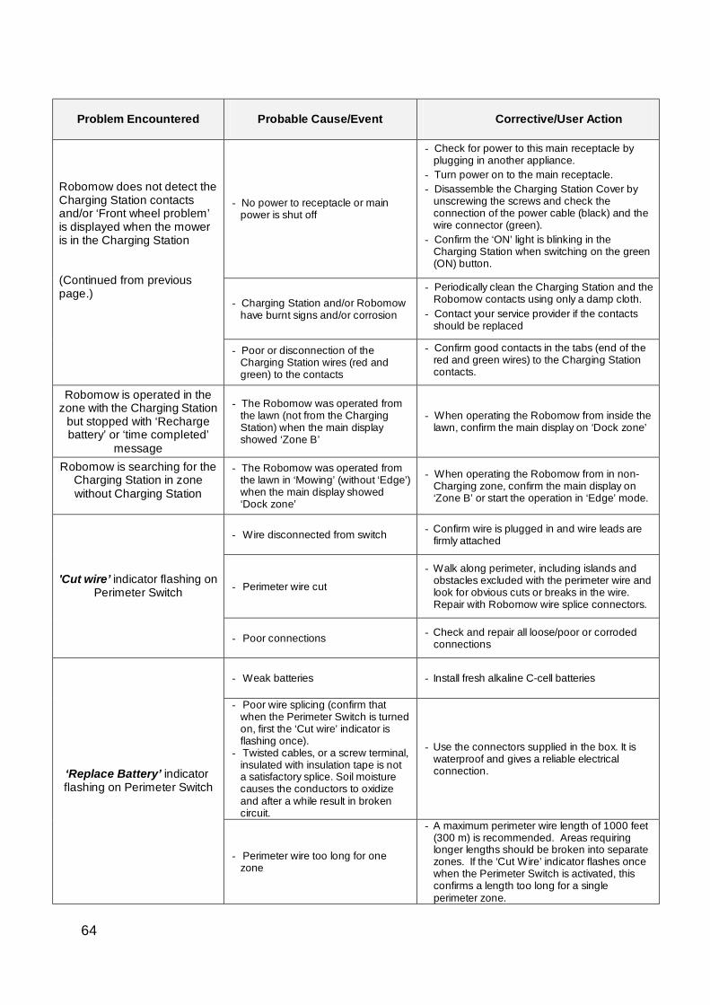
64
Problem Encountered
Probable Cause/Event
Corrective/User Action
- No power to receptacle or main power is shut off
- Check for power to this main receptacle by plugging in another appliance.
- Turn power on to the main receptacle. - Disassemble the Charging Station Cover by
unscrewing the screws and check the connection of the power cable (black) and the wire connector (green).
- Confirm the ‘ON’ light is blinking in the Charging Station when switching on the green (ON) button.
- Charging Station and/or Robomow have burnt signs and/or corrosion
- Periodically clean the Charging Station and the Robomow contacts using only a damp cloth.
- Contact your service provider if the contacts should be replaced
Robomow does not detect the Charging Station contacts and/or ‘Front wheel problem’ is displayed when the mower is in the Charging Station (Continued from previous page.)
- Poor or disconnection of the Charging Station wires (red and green) to the contacts
- Confirm good contacts in the tabs (end of the red and green wires) to the Charging Station contacts.
Robomow is operated in the zone with the Charging Station
but stopped with ‘Recharge battery’ or ‘time completed’
message
- The Robomow was operated from the lawn (not from the Charging Station) when the main display showed ‘Zone B’
- When operating the Robomow from inside the lawn, confirm the main display on ‘Dock zone’
Robomow is searching for the Charging Station in zone without Charging Station
- The Robomow was operated from the lawn in ‘Mowing’ (without ‘Edge’) when the main display showed ‘Dock zone’
- When operating the Robomow from in non-Charging zone, confirm the main display on ‘Zone B’ or start the operation in ‘Edge’ mode.
- Wire disconnected from switch - Confirm wire is plugged in and wire leads are firmly attached
- Perimeter wire cut
- Walk along perimeter, including islands and obstacles excluded with the perimeter wire and look for obvious cuts or breaks in the wire. Repair with Robomow wire splice connectors.
'Cut wire’ indicator flashing on Perimeter Switch
- Poor connections - Check and repair all loose/poor or corroded connections
- Weak batteries - Install fresh alkaline C-cell batteries
- Poor wire splicing (confirm that when the Perimeter Switch is turned on, first the ‘Cut wire’ indicator is flashing once).
- Twisted cables, or a screw terminal, insulated with insulation tape is not a satisfactory splice. Soil moisture causes the conductors to oxidize and after a while result in broken circuit.
- Use the connectors supplied in the box. It is waterproof and gives a reliable electrical connection. ‘Replace Battery’ indicator
flashing on Perimeter Switch
- Perimeter wire too long for one zone
- A maximum perimeter wire length of 1000 feet (300 m) is recommended. Areas requiring longer lengths should be broken into separate zones. If the ‘Cut Wire’ indicator flashes once when the Perimeter Switch is activated, this confirms a length too long for a single perimeter zone.
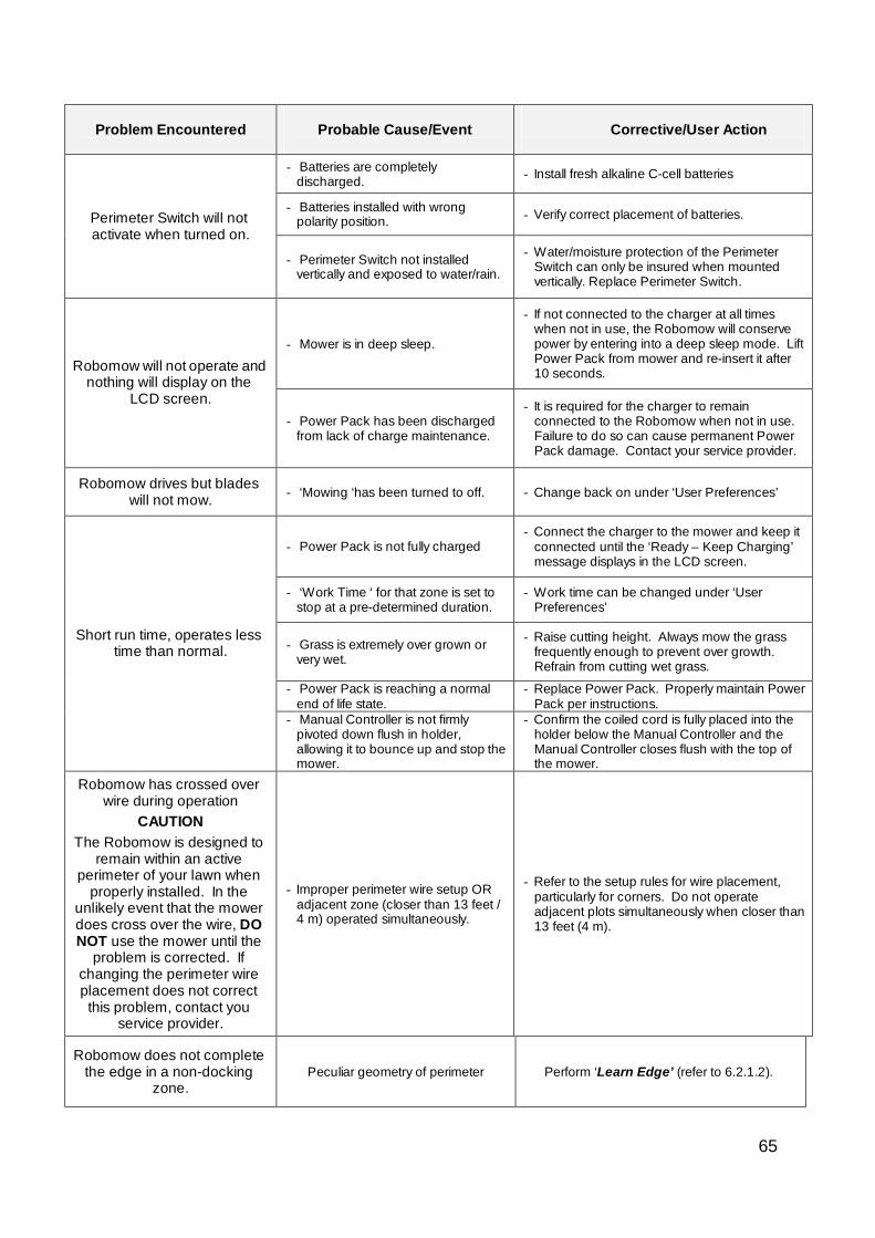
65
Problem Encountered
Probable Cause/Event
Corrective/User Action
- Batteries are completely
discharged. - Install fresh alkaline C-cell batteries
- Batteries installed with wrong polarity position. - Verify correct placement of batteries. Perimeter Switch will not
activate when turned on. - Perimeter Switch not installed
vertically and exposed to water/rain.
- Water/moisture protection of the Perimeter Switch can only be insured when mounted vertically. Replace Perimeter Switch.
- Mower is in deep sleep.
- If not connected to the charger at all times when not in use, the Robomow will conserve power by entering into a deep sleep mode. Lift Power Pack from mower and re-insert it after 10 seconds. Robomow will not operate and
nothing will display on the LCD screen.
- Power Pack has been discharged from lack of charge maintenance.
- It is required for the charger to remain connected to the Robomow when not in use. Failure to do so can cause permanent Power Pack damage. Contact your service provider.
Robomow drives but blades will not mow. - ‘Mowing ‘has been turned to off. - Change back on under ‘User Preferences’
- Power Pack is not fully charged - Connect the charger to the mower and keep it
connected until the ‘Ready – Keep Charging’ message displays in the LCD screen.
- ‘Work Time ‘ for that zone is set to stop at a pre-determined duration.
- Work time can be changed under ‘User Preferences’
- Grass is extremely over grown or very wet.
- Raise cutting height. Always mow the grass frequently enough to prevent over growth. Refrain from cutting wet grass.
- Power Pack is reaching a normal end of life state.
- Replace Power Pack. Properly maintain Power Pack per instructions.
Short run time, operates less time than normal.
- Manual Controller is not firmly pivoted down flush in holder, allowing it to bounce up and stop the mower.
- Confirm the coiled cord is fully placed into the holder below the Manual Controller and the Manual Controller closes flush with the top of the mower.
Robomow has crossed over wire during operation
CAUTION The Robomow is designed to
remain within an active perimeter of your lawn when
properly installed. In the unlikely event that the mower does cross over the wire, DO NOT use the mower until the
problem is corrected. If changing the perimeter wire placement does not correct this problem, contact you
service provider.
- Improper perimeter wire setup OR adjacent zone (closer than 13 feet / 4 m) operated simultaneously.
- Refer to the setup rules for wire placement, particularly for corners. Do not operate adjacent plots simultaneously when closer than 13 feet (4 m).
Robomow does not complete the edge in a non-docking
zone. Peculiar geometry of perimeter Perform ‘Learn Edge’ (refer to 6.2.1.2).
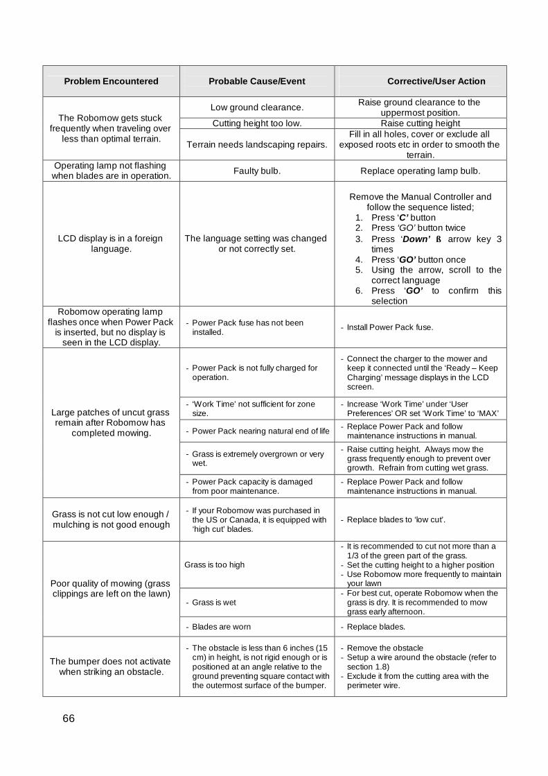
66
Problem Encountered
Probable Cause/Event
Corrective/User Action
Low ground clearance. Raise ground clearance to the uppermost position.
Cutting height too low. Raise cutting height The Robomow gets stuck frequently when traveling over
less than optimal terrain. Terrain needs landscaping repairs. Fill in all holes, cover or exclude all
exposed roots etc in order to smooth the terrain.
Operating lamp not flashing when blades are in operation. Faulty bulb. Replace operating lamp bulb.
LCD display is in a foreign language.
The language setting was changed or not correctly set.
Remove the Manual Controller and
follow the sequence listed; 1. Press ‘C’ button 2. Press ‘GO’ button twice 3. Press ‘Down’ ⇓ arrow key 3
times 4. Press ‘GO’ button once 5. Using the arrow, scroll to the
correct language 6. Press ‘GO’ to confirm this
selection Robomow operating lamp
flashes once when Power Pack is inserted, but no display is
seen in the LCD display.
- Power Pack fuse has not been installed. - Install Power Pack fuse.
- Power Pack is not fully charged for operation.
- Connect the charger to the mower and keep it connected until the ‘Ready – Keep Charging’ message displays in the LCD screen.
- ‘Work Time’ not sufficient for zone size.
- Increase ‘Work Time’ under ‘User Preferences’ OR set ‘Work Time’ to ‘MAX’
- Power Pack nearing natural end of life - Replace Power Pack and follow maintenance instructions in manual.
- Grass is extremely overgrown or very wet.
- Raise cutting height. Always mow the grass frequently enough to prevent over growth. Refrain from cutting wet grass.
Large patches of uncut grass remain after Robomow has
completed mowing.
- Power Pack capacity is damaged from poor maintenance.
- Replace Power Pack and follow maintenance instructions in manual.
Grass is not cut low enough / mulching is not good enough
- If your Robomow was purchased in the US or Canada, it is equipped with ‘high cut’ blades.
- Replace blades to ‘low cut’.
Grass is too high
- It is recommended to cut not more than a 1/3 of the green part of the grass.
- Set the cutting height to a higher position - Use Robomow more frequently to maintain
your lawn
- Grass is wet - For best cut, operate Robomow when the
grass is dry. It is recommended to mow grass early afternoon.
Poor quality of mowing (grass clippings are left on the lawn)
- Blades are worn - Replace blades.
The bumper does not activate when striking an obstacle.
- The obstacle is less than 6 inches (15 cm) in height, is not rigid enough or is positioned at an angle relative to the ground preventing square contact with the outermost surface of the bumper.
- Remove the obstacle - Setup a wire around the obstacle (refer to
section 1.8) - Exclude it from the cutting area with the
perimeter wire.
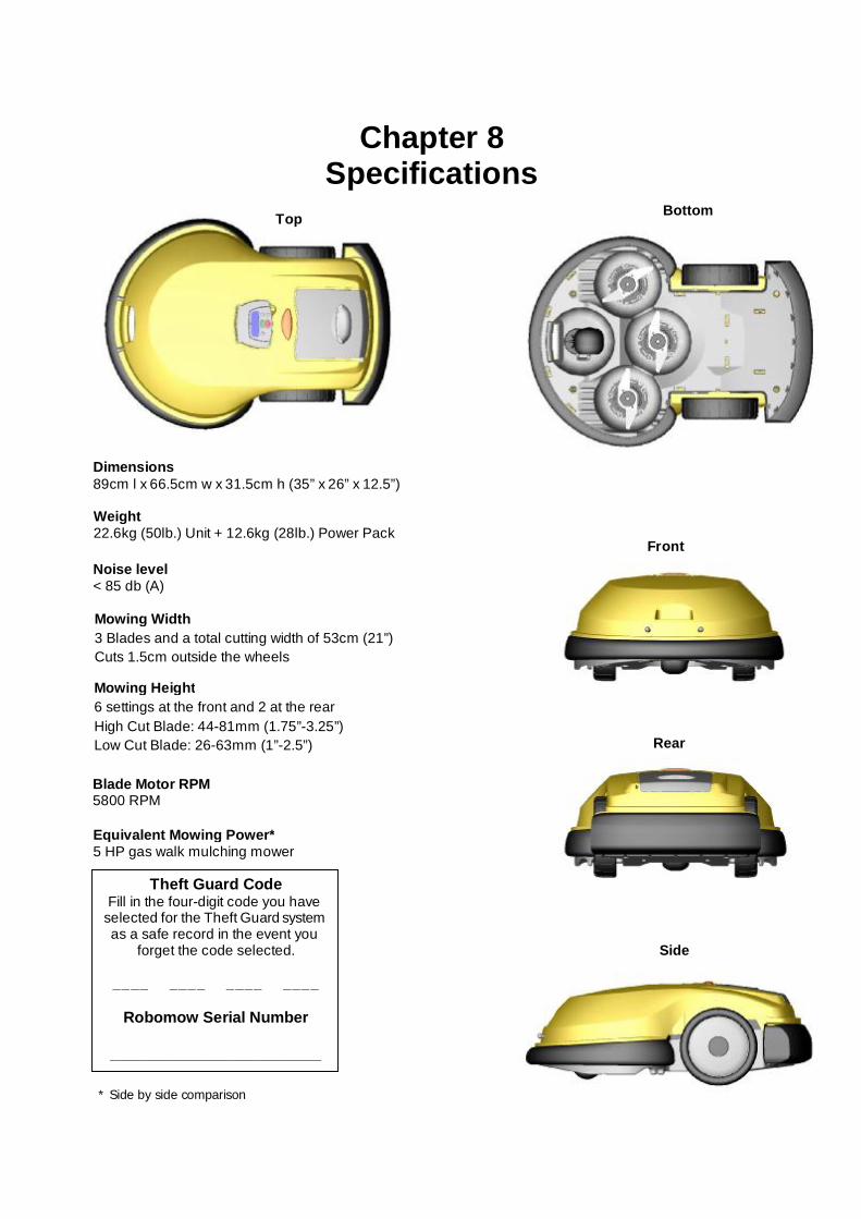
67
Theft Guard Code Fill in the four-digit code you have
selected for the Theft Guard system as a safe record in the event you
forget the code selected.
____ ____ ____ ____
Robomow Serial Number
________________________
Top Bottom
Front
Rear
Side
Chapter 8 Specifications
* Side by side comparison
Dimensions 89cm l x 66.5cm w x 31.5cm h (35” x 26” x 12.5”)
Weight22.6kg (50lb.) Unit + 12.6kg (28lb.) Power Pack
Noise level< 85 db (A)
Mowing Width3 Blades and a total cutting width of 53cm (21”)Cuts 1.5cm outside the wheels
Mowing Height6 settings at the front and 2 at the rearHigh Cut Blade: 44-81mm (1.75”-3.25”)Low Cut Blade: 26-63mm (1”-2.5”)
Blade Motor RPM5800 RPM
Equivalent Mowing Power*5 HP gas walk mulching mower
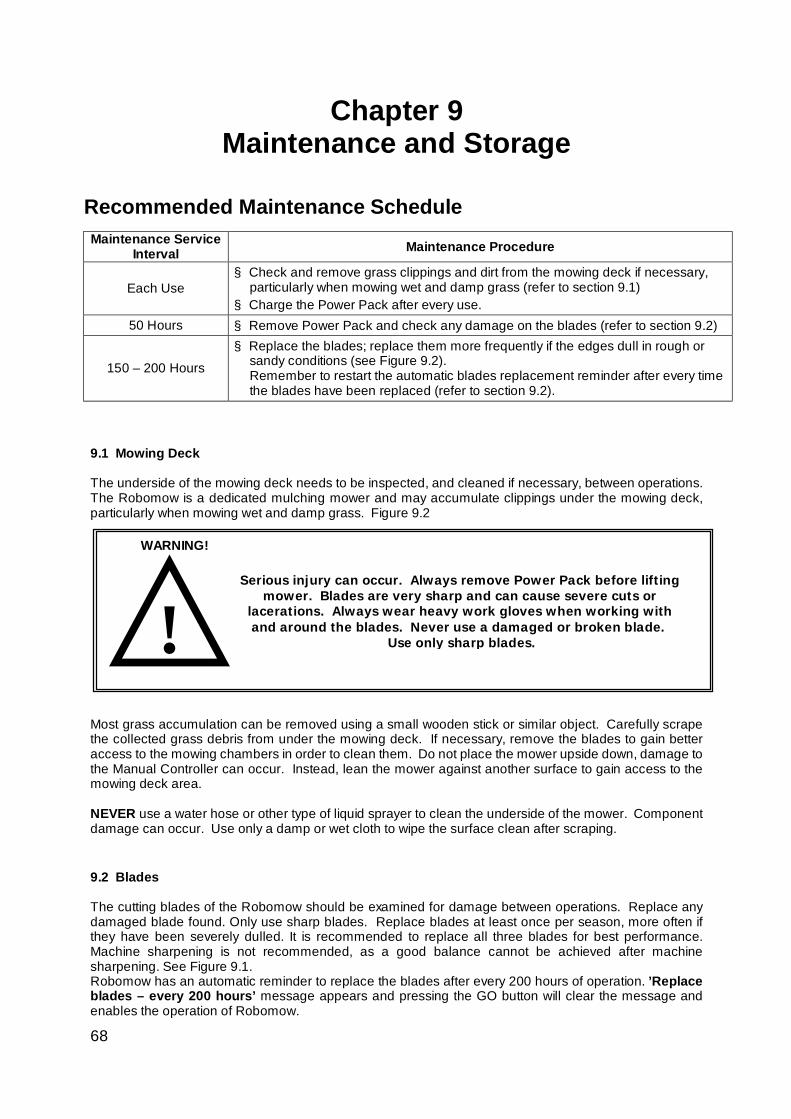
68
! Serious injury can occur. Always remove Power Pack before lifting
mower. Blades are very sharp and can cause severe cuts or lacerations. Always wear heavy work gloves when working with and around the blades. Never use a damaged or broken blade.
Use only sharp blades.
WARNING!
Chapter 9 Maintenance and Storage
Recommended Maintenance Schedule
Maintenance Service
Interval Maintenance Procedure
Each Use § Check and remove grass clippings and dirt from the mowing deck if necessary,
particularly when mowing wet and damp grass (refer to section 9.1) § Charge the Power Pack after every use.
50 Hours § Remove Power Pack and check any damage on the blades (refer to section 9.2)
150 – 200 Hours
§ Replace the blades; replace them more frequently if the edges dull in rough or sandy conditions (see Figure 9.2). Remember to restart the automatic blades replacement reminder after every time the blades have been replaced (refer to section 9.2).
9.1 Mowing Deck
The underside of the mowing deck needs to be inspected, and cleaned if necessary, between operations. The Robomow is a dedicated mulching mower and may accumulate clippings under the mowing deck, particularly when mowing wet and damp grass. Figure 9.2
Most grass accumulation can be removed using a small wooden stick or similar object. Carefully scrape the collected grass debris from under the mowing deck. If necessary, remove the blades to gain better access to the mowing chambers in order to clean them. Do not place the mower upside down, damage to the Manual Controller can occur. Instead, lean the mower against another surface to gain access to the mowing deck area.
NEVER use a water hose or other type of liquid sprayer to clean the underside of the mower. Component damage can occur. Use only a damp or wet cloth to wipe the surface clean after scraping.
9.2 Blades The cutting blades of the Robomow should be examined for damage between operations. Replace any damaged blade found. Only use sharp blades. Replace blades at least once per season, more often if they have been severely dulled. It is recommended to replace all three blades for best performance. Machine sharpening is not recommended, as a good balance cannot be achieved after machine sharpening. See Figure 9.1. Robomow has an automatic reminder to replace the blades after every 200 hours of operation. ’Replace blades – every 200 hours’ message appears and pressing the GO button will clear the message and enables the operation of Robomow.
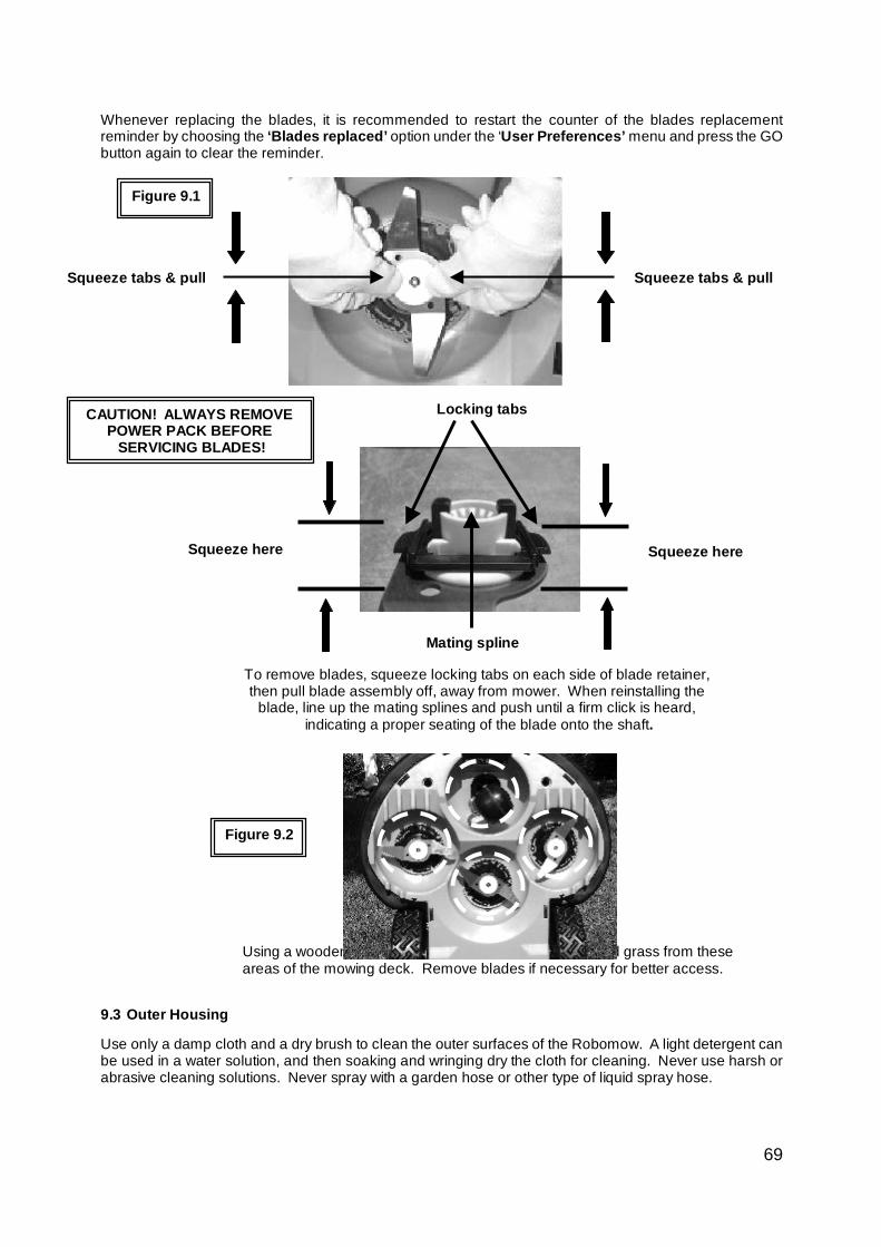
69
Whenever replacing the blades, it is recommended to restart the counter of the blades replacement reminder by choosing the ‘Blades replaced’ option under the ‘User Preferences’ menu and press the GO button again to clear the reminder.
9.3 Outer Housing
Use only a damp cloth and a dry brush to clean the outer surfaces of the Robomow. A light detergent can be used in a water solution, and then soaking and wringing dry the cloth for cleaning. Never use harsh or abrasive cleaning solutions. Never spray with a garden hose or other type of liquid spray hose.
Figure 9.1
Squeeze tabs & pull Squeeze tabs & pull
To remove blades, squeeze locking tabs on each side of blade retainer, then pull blade assembly off, away from mower. When reinstalling the
blade, line up the mating splines and push until a firm click is heard, indicating a proper seating of the blade onto the shaft.
Squeeze here Squeeze here
Locking tabs
Mating spline
Figure 9.2
Using a wooden stick or similar object, clean accumulated grass from these areas of the mowing deck. Remove blades if necessary for better access.
CAUTION! ALWAYS REMOVE POWER PACK BEFORE
SERVICING BLADES!
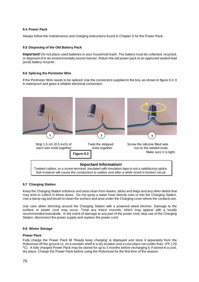
70
9.4 Power Pack
Always follow the maintenance and charging instructions found in Chapter 5 for the Power Pack.
9.5 Disposing of the Old Battery Pack
Important! Do not place used batteries in your household trash. The battery must be collected, recycled, or disposed of in an environmentally sound manner. Return the old power pack to an approved sealed lead (acid) battery recycler. 9.6 Splicing the Perimeter Wire
If the Perimeter Wire needs to be spliced: Use the connectors supplied in the box, as shown in figure 9.3. It is waterproof and gives a reliable electrical connection.
Strip 1.5 cm (0.5 inch) of Twist the stripped Screw the silicone filled wire each wire ends together ends together nut on the twisted ends.
Make sure it is tight.
Important Information!
Twisted cables, or a screw terminal, insulated with insulation tape is not a satisfactory splice. Soil moisture will cause the conductors to oxidize and after a while result in broken circuit.
9.7 Charging Station
Keep the Charging Station entrance and area clean from leaves, sticks and twigs and any other debris that may tend to collect in these areas. Do not spray a water hose directly onto or into the Charging Station. Use a damp rag and brush to clean the surface and area under the Charging cover where the contacts are.
Use care when trimming around the Charging Station with a powered weed trimmer. Damage to the surface or power cord may occur. Treat any insect mounds, which may appear with a locally recommended insecticide. In the event of damage to any part of the power cord, stop use of the Charging Station, disconnect the power supply and replace the power cord.
9.8 Winter Storage
Power Pack Fully charge the Power Pack till ‘Ready keep charging’ is displayed and store it separately from the Robomow off the ground i.e. on a wooden shelf in a dry location and a cool place not colder than -4ºF (-20 ºC). A fully charged Power Pack may be stored for up to 3 months before recharging it, if stored in a cool, dry place. Charge the Power Pack before using the Robomow for the first time of the season.
1 2 3
Figure 9.3
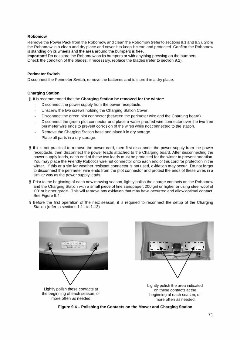
71
Lightly polish these contacts at the beginning of each season, or
more often as needed.
Lightly polish the area indicated on these contacts at the
beginning of each season, or more often as needed.
Figure 9.4 – Polishing the Contacts on the Mower and Charging Station
Robomow Remove the Power Pack from the Robomow and clean the Robomow (refer to sections 9.1 and 9.3). Store the Robomow in a clean and dry place and cover it to keep it clean and protected. Confirm the Robomow is standing on its wheels and the area around the bumpers is free. Important! Do not store the Robomow on its bumpers or with anything pressing on the bumpers. Check the condition of the blades; if necessary, replace the blades (refer to section 9.2). Perimeter Switch Disconnect the Perimeter Switch, remove the batteries and to store it in a dry place. Charging Station § It is recommended that the Charging Station be removed for the winter:
- Disconnect the power supply from the power receptacle. - Unscrew the two screws holding the Charging Station Cover. - Disconnect the green plot connector (between the perimeter wire and the Charging board). - Disconnect the green plot connector and place a water proofed wire connector over the two free
perimeter wire ends to prevent corrosion of the wires while not connected to the station. - Remove the Charging Station base and place it in dry storage. - Place all parts in a dry storage.
§ If it is not practical to remove the power cord, then first disconnect the power supply from the power
receptacle, then disconnect the power leads attached to the Charging board. After disconnecting the power supply leads, each end of these two leads must be protected for the winter to prevent oxidation. You may place the Friendly Robotics wire nut connector onto each end of this cord for protection in the winter. If this or a similar weather resistant connector is not used, oxidation may occur. Do not forget to disconnect the perimeter wire ends from the plot connector and protect the ends of these wires in a similar way as the power supply leads.
§ Prior to the beginning of each new mowing season, lightly polish the charge contacts on the Robomow and the Charging Station with a small piece of fine sandpaper, 200 grit or higher or using steel wool of ‘00’ or higher grade. This will remove any oxidation that may have occurred and allow optimal contact. See Figure 9.4.
§ Before the first operation of the next season, it is required to reconnect the setup of the Charging Station (refer to sections 1.11 to 1.13)
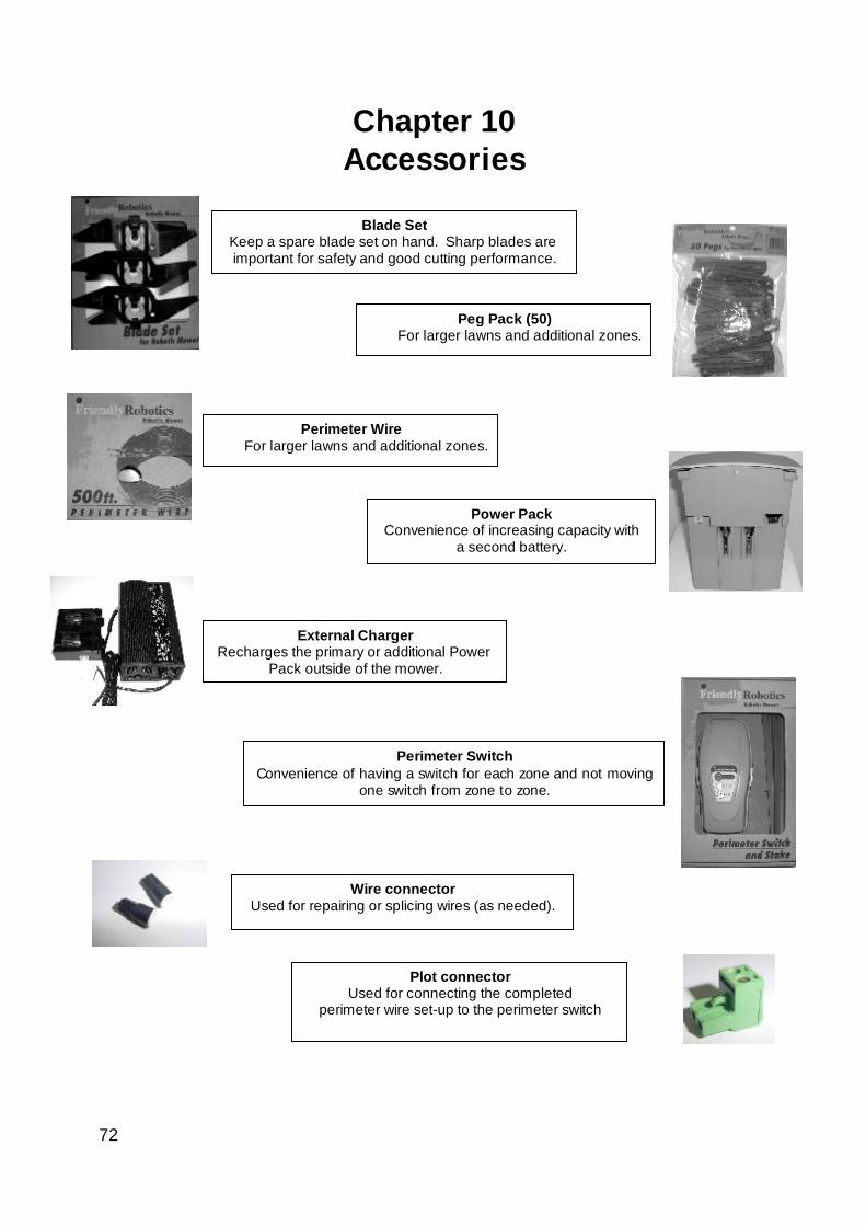
72
Chapter 10 Accessories
Perimeter Switch Convenience of having a switch for each zone and not moving
one switch from zone to zone.
Peg Pack (50) For larger lawns and additional zones.
Perimeter Wire For larger lawns and additional zones.
Power Pack Convenience of increasing capacity with
a second battery.
Plot connector Used for connecting the completed
perimeter wire set-up to the perimeter switch
External Charger Recharges the primary or additional Power
Pack outside of the mower.
Blade Set Keep a spare blade set on hand. Sharp blades are important for safety and good cutting performance.
Wire connector Used for repairing or splicing wires (as needed).

73
Tips for maintaining your lawn Robomow®- Lawn care has never been so easy
Best time to mow
Mow your lawn when the grass is dry. This prevents the clippings from clumping and leaving piles on the lawn.
Mow it late in the day rather than during the heat of the day.
Mowing frequency
Mow often, producing short, small clippings. During the active growing season the mowing frequency should be increased to once every 3-5 days, before the grass is too long. Short clippings decompose quickly and will not cover the grass surface. If the grass gets too high, raise the cutting height, mow, then gradually lower it over several mowings.
Cutting Height
Follow the "1/3 rule:" mow no more than 1/3 of the length of the grass. Proper mowing will produce short clippings that will not cover up the grass surface. You may have to cut the lawn more frequently, or double cut, when the lawn is growing fast, such as in the spring.
Water Grasscycling reduces the amount of water needed by lawns since the clippings are about 80 - 85% water. Grasscycling slows evaporation losses from the soil surface, and conserves water. Most lawns need less water when Grasscycling. Watering Water your lawn between 4 a.m. and 8 a.m. in the morning, so water has time to soak into the soil before the heat of the sun causes evaporation. Your lawn needs 1 to 1-1/2" (3-4cm) of water weekly. Deep watering allows grass to develop a deep root system, enabling the lawn to resist disease and drought. Do not over water Too much water is not only wasteful but can also increase turf growth, which requires more frequent mowing. Let the soil partially dry out between watering. Water when the top two inches of soil have dried out. Use an object such as a screwdriver to probe your soil and measure the depth of the moisture. Fertilization Grasscycling reduces the amount of lawn fertilizer needed because the clippings provide about 1/4 of a lawn's annual needs. Blades
Keep your mower blades sharp. Sharp blades provide a clean, safe and efficient cut. Dull mower blades will tear and shred the tips of the grass, which can provide an entry point for disease organisms and weaken the grass plant. It is recommended to replace all three Robomow blades once a year.
Thatch
Clippings and thatch are simply not connected. As mentioned previously, grass clippings are approximately 80-85 percent water with only small amounts of lignin, and decompose rapidly.
When we stop and think about it, golf courses, sports fields, and parks have been mowing grass for years and recycling with no grass catchers. A small amount of thatch (approximately 1/2 inch) is actually beneficial to a lawn. Grass clippings protect your lawn's root system from heat and water loss.

74
Friendly Robotics RL Series Limited Warranty
Friendly Robotics warrants to the original purchaser that the RL series ‘Product’ is free from defects in materials and workmanship when used under normal residential* purposes for a period of 24 months, 12 months for the batteries, beginning from the date of purchase. Product accessories, including replacement batteries, are warranted for a period of ninety days from the date of purchase. This warranty provides for the cost of parts and labor to repair covered defects when performed by an authorized Friendly Robotics service and warranty facility. A valid proof of purchase is required for warranty repairs. The limited warranty does not cover transportation costs of any kind. The owner bears all responsibility for transportation costs to an authorized Friendly Robotics service and warranty facility. *Normal residential purposes is defined as use of the product on the same lot as your primary home. Use at more than one location is considered commercial use, and this warranty would not apply. Items and Conditions Not Covered This express warranty does not cover the following: • Cost of regular maintenance service parts or procedures, such as blades or blade sharpening. • Any product or part that has been altered, misused, abused or requires replacement or repair due to accidents or
lack of proper maintenance. • Normal wear and tear, including fading of paint or plastic parts. • Cost of installation or reinstallation, removal of installation or any costs or damages associated with improper
installation or use of product. • Any product that has been opened, repaired, modified or altered by anyone other than a Friendly Robotics
authorized repair facility. • Repairs necessary due to improper battery care and/or improper charging process such as charging in
wet conditions, electrical supply irregularities, or failure to properly prepare the mower or battery prior to any period of non-use.
• Repairs necessary due to water damage, other than incidental rain exposure, repairs due to lighting or other acts of God.
Instructions for Obtaining Warranty Service Should you feel your Friendly Robotics product contains a defect in materials or workmanship, contact the retailer who sold you the product. Owner Responsibilities You must maintain and care for your Friendly Robotics product by following the maintenance and care procedures described in the owner/operator manual. Routine maintenance, whether performed by a service provider or by you, is at your expense. General Conditions Repair by an authorized Friendly Robotics service and warranty repair facility is your sole remedy under this warranty. There is no other express or implied warranty. All implied warranties of merchantability and fitness for use are limited to the duration of this express warranty. Friendly Robotics is not liable for indirect, incidental or consequential damages in connection with the use of the Friendly Robotics Product covered by this warranty, including any cost or expense of providing substitute equipment or service during reasonable periods of malfunction or non-use pending completion of repairs under this warranty. Some states do not allow exclusions of incidental or consequential damages, or limitations on how long an implied warranty lasts, so the above exclusion and limitations may not apply to you. This warranty gives you specific legal rights, and you may also have other rights, which vary from state to state.
Always follow the safety instructions specified in this Manual

75
To register your product online, go to
www.robomow.com/register/
www.robomow.com / www.robomow.eu