Embed Size (px)
Citation preview

RA
DE
X®-N
RIG
IFLE
X®-N
RIG
IFLE
X®-H
P
121You will find continuously updated data in our online catalogue at www.ktr.com.
RADEX®-NSteel lamina coupling
RIGIFLEX®-NSteel lamina coupling
RIGIFLEX®-HPHigh-performance steel lamina coupling

122
RADEX®-N Steel lamina coupling
You will find continuously updated data in our online catalogue at www.ktr.com.
Table of contents
RADEX®-N Steel lamina coupling 121Coupling selection steel lamina coupling 123Description of coupling 125General information 126Types and applications 127Technical data 128Standard types 130Customized types 132Standard series NANA 3 for pump drives according to API 610 133Corrosion-resistant type for big shaft distance dimensions 134
RIGIFLEX®-N Steel lamina couplingDescription of coupling 135Technical data 136Type A 138
RIGIFLEX®-HP High Performance - StahllamellenkupplungCoupling selection RIGIFLEX®-HP 139Type C 140Type L 141Technical data of RIGIFLEX®-HP 142
NEW

RA
DE
X®-N
RIG
IFLE
X®-N
RIG
IFLE
X®-H
P
123
RADEX®-N Steel lamina coupling
You will find continuously updated data in our online catalogue at www.ktr.com.
Guidelines for operating factor SBMachine SBConstruction machinery 2,0Agitators 1,0 - 2,0Centrifuges 1,5Conveyors 2,0Elevators 2,0Fans/Blowers 1,5Generators 1,0Calanders 2,0Grinders, crushers 2,5Textile machinery 2,0Rolling mills 2,5Woodworking machinery 1,5Mixers and extruders 2,0Stamps, presses 2,5Machine tools 2,0Grinders 2,5Packaging machines 1,0Roller drives 2,5Piston pumps 2,5Centrifugal pumps 1,5Piston compressors 2,5Turbo compressors 2,0
Coupling selection steel lamina coupling1. Permissible displacements:∆Ka: Permissible axial displacement∆Kw: Permissible angular displacement∆Kr: Permissible radial displacementStahllamellenkupplungen sind so ausgelegt, dass die maximal zu-lässige winkelige Auslenkung ∆Kw in jedem Lamellenpaket aufge-nommen werden darf. Die maximal mögliche Winkelauslenkung zweier miteinander verbundener Wellen beträgt also 2 ∆Kw. Die maximale Winkelauslenkung pro Lamellenpaket sind in der Tabelle “Technische Daten” aufgeführt.
Angular displacement
The permissible radial displacement ΔKr with distance g of the cou-pling elements is
∆Kr = g tan (∆Kw)
Radial displacement
The table “Technical data” (RADEX®-N page 126/127 and RIGIFLEX®-N page 134/135) shows the max. permissible radial displacements ΔKr for every size and type based on the given standard lengths of the spacers as well as the permissible angular displacement ΔKw of the coupling elements.The max. permissible axial displacements ΔKa for every size and type are also mentioned in the table “Technical data”.The figures of the permissible displacements indicated are depend-ent on each other!With an increasing axial displacement ΔKa the permissible angular displacement ΔKw decreases and thus the radial displacement ΔKr. (See our mounting instructions at www.ktr.com).
Description Symbol Definition or explanation
Rated torque of coupling TKNTorque which can be transmitted con-tinuously over the entire speed range of the coupling.
Vibratory torque of coupling TKW
Torque amplitude of the permissible pe-riodic torque fluctuation with a frequency of 10 Hz and a basic load of TKN or pulsating load up to TKN.
Maximum torque of coupling TKmax
Torque which can be transmitted during the entire life of the coupling ≥ 105 times as pulsating load or 5 x 10⁴ times as alternating load.

124
RADEX®-N Steel lamina coupling
You will find continuously updated data in our online catalogue at www.ktr.com.
Coupling selection steel lamina couplingSelection of the coupling size3. Drives with periodical torsional vibrationsFor drives subject to dangerous torsional vibrations (e. g. diesel engines, piston compressors, piston pumps, generators, etc.) it is necessary to perform a torsional vibration calculation (please con-sult with us).
3.1 Loading by rated torqueTaking into account the operating factor SB, directional factor SR and temperature factor St, the permissible rated speed must be at least as big as the rated torque TN of the machine.
The rated torque TKN of the coupling is:
TKN ≥ TN SB St SR
TN = Torque of the machineSB = Operating factor (see table on page 123)SR= Factor of direction = 1,00 same torque direction = 1,70 torque direction switchingSt = Operating temperature Temperature factor
°C -30 0 +150 +200 +230 +270
Factor 1,00 1,00 1,00 1,10 1,25 1,43
3.2 Passing through resonanceThe peak torque TSR arising while passing through resonance must not exceed the permissible maximum torque of the coupling TKmax.
3.3 Loading by vibratory torque The permissible vibratory torque of the coupling TKW must not be exceeded by the maximum periodical vibratory torque of the machine TW.
TKW ≥ TW
TKmax ≥ TSR
Selection of the coupling size2. Drives without periodical torsional vibrationsFor example centrifugal pumps, fans, screw compressors, etc. The coupling selection requires that the rated torque TKN and the maxi-mum torque TKmax are reviewed.
2.1 Loading by rated torqueTaking into account the operating factor SB, directional factor SR and temperature factor St, the permissible rated speed must be at least as big as the rated torque TN of the machine.
The rated torque TKN of the coupling is:
TKN ≥ TN SB St SR
TN = Torque of the machineSB = Operating factor (see table on page 123)SR= Factor of direction = 1,00 same torque direction = 1,70 torque direction switchingSt = Operating temperature Temperature factor
°C -30 0 +150 +200 +230 +270
Factor 1,00 1,00 1,00 1,10 1,25 1,43
2.2 Loading by torque shocksThe permissible maximum torque TKmax of the coupling must be at least as big as the sum of the peak torque TS and rated torque TN of the machine taking into account the operating factor SB, temperature factor St and directional factor SR. This applies in case that the rated torque of the machine is superimposed by a shock (e. g. starting of the engine). For drives with A. C. motors and big masses on the load side we would recommend calculations by our simulation program (please consult with us).
TKmax ≥ (TN + TS) St SR
TS = Peak torque

RA
DE
X®-N
RIG
IFLE
X®-N
RIG
IFLE
X®-H
P
125
RADEX®-N Steel lamina coupling
You will find continuously updated data in our online catalogue at www.ktr.com.
Description of coupling
Use in explosive applicationsRADEX®-N couplings are suitable for power transmission in drives in hazardous areas. The couplings are certified and confirmed according to EC standard 94/9/EC (ATEX 95) as units of category 2G/2D and thus suitable for the use in hazardous areas of zone 1, 2, 21 and 22. With the use in explosive areas clamping ring hubs (clamping hubs without feather key for category 3 only) have to be selected such that there is a safety factor of s = 2 between the peak torque of the unit including all operating parameters and the friction and rated torque of the coupling. You will find further details about this subject at www.ktr.com.
HubSpacer
The RADEX®-N is a backlash-free, torsionally rigid and maintenance-free all-steel coupling. The laminas that are extremely rigid in sense of rotation are made of high-strength, stainless spring steel and enable a compensation for high displacements with low restoring forces. By reason of the all-steel design the RADEX®-N can be used in drives with temperatures of up to 280 °C.
FEM-optimized lamina shapeThe steel lamina sets made of stainless spring steel were developed on the basis of FEM calculations. Taking into account the necessary pos-sibilities of displacements of the coupling the optimum shape regarding torque transmission and torsional rigidity was aimed at. The fitted shape of the steel laminas on the outside diameter is the result of this optimiza-tion calculation.
Lamina sets with dowel screwsThe „heart“ of the steel lamina coupling are the lamina sets and their connection to the hubs or spacers. High-strength, special dowel screws that are alternately screwed to hubs and spacer enable a combination of frictional engagement and positive locking. Thus a high power density with at the same time ease of displacement and low restoring forces is ensured. Due to the special design of the RADEX®-N components the lamina sets are prestressed „artificially“. Hereby the torsional rigidity is increased by approx. 30 % and at the same time the well-known prob-lem regarding the axial vibrations of the spacer is prevented.
Dowel screw (combination of frictional engagement and positive locking)
Lamina set with screws

126
RADEX®-N Steel lamina coupling
You will find continuously updated data in our online catalogue at www.ktr.com.
General information
Hub designs
Delivery conditionRADEX®-N couplings are supplied as individual parts (can be delivered assembled on request). The hubs can be supplied unbored or with finish bore and feather keyway or with a frictionally engaged shaft-hub-connection. The shaft-hub-connection needs to be inspected by the customer (if necessary, please consult with KTR).
Assembly and operating advice(Please see our mounting instructions KTR standard 47110 at www.ktr.com.) For the assembly it is impor-tant to make sure that the lamina sets are assembled free from distortion in axial direction. If the finish bore is machined by the customer, the concentric and axial running tolerances have to be observed (see sketch).
Balancing:On request of the customer the RADEX®-N couplings can be balanced. For usual applications this is not necessary due to the accurate machining of the coupling. Please consult with KTR, if necessary.
Safety regulations:The coupling must be selected in a way that the permissible coupling load is not exceeded in any operating condition. For that purpose a comparison between the actual loads and the permissible coupling characteristics has to be performed. The customer must protect rotating parts from accidental contact (Safety of Machines DIN EN 292 part 2). Please take precautions that there is a sufficient coupling protection in case of a fracture of the coupling caused by overload.
Installation:RADEX®-N couplings are designed for horizontal installation. For vertical installation the spacer might have to be supported (see sketch). Please consult with us.
Design 1.0 Hub with feather keyway and thread for setscrews
Design 2.5 clamping hub with two slots without feather keyway
Positive locking torque transmission, permissible torque depending on the permissible surface pressure. Not suitable as backlash-free torque transmission with heavily reversing operation.
Frictionally engaged, backlash-free shaft-hub-connection. Transmittable torques depending on bore diameter. Only permissible for ATEX cat. 3.
Design 1.1 hub without keyway, with fixing screw Design 2.6 clamping hub with two slots with feather keyway
Non-positive torque transmission for crimped and bonded connections (no ATEX release)
Positive locking shaft-hub-connection with additional frictionally engaged operation. The frictionally engaged operation prevents or reduces reverse backlash.
Design 1.2 Hub without feather keyway, without thread for setscrews
Non-positive torque transmission for crimped and bonded connections (no ATEX release)
Design 6.0 clamping ring hub
Integrated frictionally engaged shaft-hub-connection for the transmission of higher torques. Clamping screws on lamina side. Transmittable torques depending on bore diameter. Suitable for high speeds.
Design 6.5 clamping ring hub
Integrated frictionally engaged shaft-hub-connection for the transmission of higher torques. Clamping screws externally. Transmittable torques depending on bore diameter. Suitable for high speeds.

RA
DE
X®-N
RIG
IFLE
X®-N
RIG
IFLE
X®-H
P
127
RADEX®-N Steel lamina coupling
You will find continuously updated data in our online catalogue at www.ktr.com.
Types and applications
Type NN (see page 130)
Type NANA 1 / NANA 2 (see page 132)
Type NANA 3 (see page 133)
Type NANA 4 (see page 134)
Type NNW (see page 132)
Type NNZ (see page 131)
Type NENE 1 (see page 131)
Type Characteristics Applications
z Single cardanic design z Only angular and axial displace-ment permissible
z High torsional rigidity z Compact dimensions
z Mixers z Agitators z Immersion pumps z Fans z Applications with high radial load
z Double cardanic design z Compensating for high mis-alignment with low restoring forces
z Standard spacers available from stock
z Paper machines z Printing and processing machines
z Conveyors z Steel mills z Generators z Grinding machines
z Double cardanic design z Spacers adapted to standard dimensions of pumps
z Radial assembly, no shifting of the machine required
z Available according to API 610
z Process pumps z Water pumps z Pumps according to API standard
z Turbines z Compressors
z Spacers can be determined by the customer
z Maximum shaft distance dimen-sion up to approx. 6 m
z Welded intermediate pipes for high torsional rigidity
z Foil and paper machines z Pallet and conveyor systems
z Robotic palletizers z Test benches z Cooling towers/blowers
z Spacers can be determined by the customer
z Coupling consisting of 2 times type NN with intermediate shaft
z For drives with relatively low speeds
z Low speed drives with big shaft distance dimensions
z Agitators z Crushers z Presses z Packaging machines
z Compact double cardanic de-sign
z Cannot be radially assembled z With intermediate disk z Ideal for replacement of curved-tooth gear couplings from steel
z Standard type up to size 70
z Robotics z Paper machines and inserters
z Machine tools z Packaging machines z Test benches
z With reduced hubs z Compact double cardanic de-sign
z Spacer cannot be radially as-sembled
z Variable spacer length
z Applications with short shaft distance dimen-sions
z Replacement for curved-tooth gear couplings from steel

128
RADEX®-N Steel lamina coupling
You will find continuously updated data in our online catalogue at www.ktr.com.
Permissible speeds and torsional stiffness figures
Size Max. speed [rpm](higher speeds on request)
Torsion spring rigidity x 106 [Nm/rad] per lamina set Size
Max. speed [rpm] (higher speeds on request) Torsion spring rigidity x 106 [Nm/rad]
per lamina set
20 20000 0,017 156 3500 9,2025 16000 0,028 166 3300 13,835 13000 0,092 186 3000 18,438 12000 0,198 206 2800 23,842 10000 0,282 246 2300 28,450 8000 0,501 286 2000 41,460 6700 0,560 336 1800 48,570 5900 0,900 138 3800 13,280 5100 1,140 158 3500 18,385 4750 1,520 168 3300 26,290 4300 1,940 188 3000 31,0
105 4000 2,540 208 2800 52,0115 3400 3,480 248 2300 71,0135 3000 6,850 288 2000 108,0136 3800 7,64 338 1800 156,0
Torques and displacements
Size Lamina type
Torques [Nm]1) Permissible displacements 2)
TKN TK max TKW
Angular [°] each lamina
Axial [mm] Radial [mm]
NNNANA 1/ NANA2/
NNZ NANA 1 NANA 2/NNZ20
4 hole lamina
15 30 5 1,0 0,60 1,2 0,5 0,125 30 60 10 1,0 0,80 1,6 0,5 0,235 60 120 20 1,0 1,00 2,0 0,5 0,238 120 240 40 1,0 1,20 2,4 0,6 0,342 180 360 60 1,0 1,40 2,8 0,6 0,350 330 660 110 1,0 1,60 3,2 0,8 0,460
6 hole lamina
690 1380 230 1,0 1,00 2,0 1,5 0,870 1100 2200 370 1,0 1,10 2,2 1,8 1,080 1500 3000 500 1,0 1,30 2,6 2,1 1,285 2400 4800 800 1,0 1,30 2,6 2,2 1,290 4500 9000 1500 1,0 1,00 2,0 2,2 1,1
105 5100 10200 1700 1,0 1,20 2,4 2,4 1,4115 9000 18000 3000 1,0 1,40 2,8 2,5 1,5135 12000 24000 4000 1,0 1,75 3,5 3,8 –136 17500 35000 8750 0,7 1,85 3,7156 25000 50000 12500 0,7 2,10 4,2166 35000 70000 17500 0,7 2,25 4,5186 42000 84000 21000 0,7 2,40 4,8206 52500 105000 26250 0,7 2,60 5,2246 90000 180000 45000 0,7 3,00 6,0286 150000 300000 75000 0,7 3,35 6,7336 210000 420000 105000 0,7 3,75 7,5 Depending on 138
8 hole lamina
23000 46000 11500 0,5 1,30 2,6 distance dimension E158 33000 66000 16500 0,5 1,40 2,8168 45000 90000 22500 0,5 1,50 3,0188 56000 112000 28000 0,5 1,60 3,2208 70000 140000 35000 0,5 1,75 3,5248 120000 240000 60000 0,5 2,00 4,0288 200000 400000 100000 0,5 2,40 4,5338 280000 560000 140000 0,5 2,50 5,0
NEW
NEW
Technical data
Size 20 – 50 (4 hole lamina)
Size 60 – 135 (6 hole lamina)
Size 138 – 338 (8 hole lamina)
Size 136 – 336 (6 hole lamina)
The following lamina types are distinguished with RADEX®-N
1) For selection of coupling see page 123/124. 2) The permissible displacement figures mentioned are maximum figures which must not arise at the same time. If radial, axial and angular displacements arise in parallel, the figures need to be reduced.

RA
DE
X®-N
RIG
IFLE
X®-N
RIG
IFLE
X®-H
P
129
RADEX®-N Steel lamina coupling
You will find continuously updated data in our online catalogue at www.ktr.com.
Standard hub 1.0 with keyway according to DIN 6885 sheet 1Size dmax. G t TA [Nm] Size dmax. G t TA [Nm]20 20 M5 6 2,0 105 105 M12 30 40,025 25 M5 8 2,0 115 115 M12 30 40,035 35 M6 15 4,8 135 135
On request of customer
38 38 M6 15 4,8 136 / 138 13542 42 M8 20 10,0 156 / 158 15050 50 M8 20 10,0 166 / 168 16560 60 M8 20 10,0 186 / 188 18070 70 M10 20 17,0 206 / 208 20080 80 M10 20 17,0 246 / 248 24085 85 M10 25 17,0 286 / 288 28090 90 M12 25 40,0 336 / 338 330
Backlash-free shaft-hub connections without feather key
Cylindrical bores
Weights and mass moments of inertia
Size Hub 1)
[kg] / [kgm2]Lamina set
[kg] / [kgm2]NN 1) complete
[kg] / [kgm2]NANA 1 1) complete
[kg] / [kgm2]NANA 2 1) complete
[kg] / [kgm2]NNZ 1) complete
[kg] / [kgm2]
20 0,13 / 0,000043 0,04 / 0,00002 0,3 / 0,00011 0,6 / 0,000204 – 0,4 / 0,00016625 0,2 / 0,000116 0,08 / 0,00005 0,56 / 0,00028 0,9 / 0,000522 – 0,8 / 0,00041435 0,6 / 0,00042 0,10 / 0,00010 1,2 / 0,00094 1,9 / 0,00158 – 1,6 / 0,0012938 0,8 / 0,00073 0,20 / 0,00026 1,8 / 0,0017 2,8 / 0,00303 – 2,4 / 0,0024742 1,1 / 0,00123 0,25 / 0,00040 2,4 / 0,0029 3,6 / 0,00482 – 3,1 / 0,0040950 1,7 / 0,00291 0,46 / 0,0010 4,0 / 0,0068 6,2 / 0,0118 – 5,1 / 0,0093260 1,9 / 0,00378 0,40 / 0,0012 4,2 / 0,0087 6,0 / 0,0141 5,8 / 0,0138 5,3 / 0,012070 2,8 / 0,00714 0,42 / 0,0016 6,0 / 0,016 8,6 / 0,0253 8,2 / 0,0242 7,5 / 0,021480 4,1 / 0,0134 0,72 / 0,0037 9,0 / 0,031 12,6 / 0,0476 12,0 / 0,0458 11,1 / 0,041085 5,1 / 0,0195 1,0 / 0,0065 11,2 / 0,046 16,2 / 0,0734 15,5 / 0,0711 14,8 / 0,065090 6,2 / 0,0282 2,3 / 0,0162 14,7 / 0,073 22,0 / 0,121 21,3 / 0,119 20,1 / 0,108
105 7,6 / 0,0414 2,2 / 0,0180 17,4 / 0,101 25,8 / 0,165 24,6 / 0,159 23,1 / 0,145115 12,0 / 0,0899 4,0 / 0,0433 27,9 / 0,223 42,8 / 0,381 41,2 / 0,372 38,3 / 0,333135 19,0 / 0,187 7,3 / 0,105 45,1 / 0,478 71,3 / 0,835 – –136 16,8 / 0,153 7,9 / 0,113 41,4 / 0,419
Mounting dimension E as Mounting dimension E as
–156 20,2 / 0,217 11,9 / 0,200 52,2 / 0,634
indicated by the customer indicated by the customer
–166 30,0 / 0,373 12,3 / 0,255 72,3 / 1,001 –186 42,0 / 0,629 12,7 / 0,318 96,7/ 1,576 –206 55,1 / 1,004 18,2 / 0,548 128,3 / 2,556 –246 85,9 / 2,229 31,2 / 1,304 203,1 / 5,762 –286 145,1 / 4,977 44,4 / 2,495 334,4 / 12,449 –336 223,9 / 10,486 64,2 / 4,74 512,0 / 25,712 –138 16,2 / 0,145 9,9 / 0,143 42,3 / 0,433 –158 19,5 / 0,205 14,9 / 0,252 54,0 / 0,662 –168 29,4 / 0,360 15,2 / 0,318 74,0 / 1,038 –188 41,7/ 0,611 15,6 / 0,396 99,0 / 1,618 –208 54,1 / 0,971 22,4 / 0,680 130,5 / 2,622 –248 84,0 / 2,144 38,2 / 1,605 206,2 / 5,893 –288 142,5 / 4,823 53,8 / 3,056 338,8 / 12,702 –338 220,1 / 10,18 78,0 / 5,817 518,2 / 26,177 –
NEW
NEW
Technical data
1) Hubs with max. bore
Clamping ring hub type 6.0 (clamping screws internally)
Design with CLAMPEX® element type 603
Clamping ring hub type 6.5 (clamping screws externally)
Selection: In case of use in hazardous areas the clamping ring hubs must be selected in a way that there is a minimum safety factor of s = 2 between the peak torque (including all operating parameters) and the nominal torque and frictional torque of engagement of the coupling.
130 You will find continuously updated data in our online catalogue at www.ktr.com.
RADEX®-N Steel lamina coupling
RADEX®-N Types NN, NANA 1, NANA 2
SizeMax. finish bore Dimensions [mm]
d1/d2 D DA l1/l2 LG1 E1 LG2 E2 LG3 E320 20 32 56 20 45 5 100 60 – –25 25 40 68 25 56 6 110 60 – –35 35 54 82 40 86 6 150 70 – –38 38 58 94 45 98 8 170 80 – –42 42 68 104 45 100 10 170 80 – –50 50 78 126 55 121 11 206 96 – –60 60 88 138 55 121 11 206 96 170 6070 70 102 156 65 141 11 246 116 200 7080 80 117 179 75 164 14 286 136 233 8385 85 123 191 80 175 15 300 140 246 8690 90 132 210 80 175 15 300 140 251 91
105 105 147 225 90 200 20 340 160 281 101115 115 163 265 100 223 23 370 170 309 109135 135 184 305 135 297 27 520 250 – –136 135 180 300 135 293 23156 150 195 325 150 327 27166 165 225 350 165 361 31186 180 250 380 185 401 31206 200 275 420 200 437 37246 240 320 500 240 524 44286 280 383 567 280 612 52336 330 445 660 330 718 58 Indicated by the customer
138 135 180 300 135 293 23
158 150 195 325 150 327 27168 165 225 350 165 361 31188 180 250 380 185 401 31208 200 275 420 200 437 37248 240 320 500 240 524 44288 280 383 567 280 612 52338 330 445 660 330 718 58
NEW
NEW
RADEX®-N 60 NANA 1 Ø50 Ø60
Coupling size Type Finish bore d1 Finish bore d2
z Standard types available from stock z Single and double cardanic types z Optionally available with frictionally engaged shaft-hub-con-nection
z Finish bore according to ISO fit H7, feather keyway according to DIN 6885 sheet 1 - JS9
z -Approved and certified according to EC Standard 94/9/EC
z From size 136 screwing of laminas by means of clamping nut (see assembly instructions KTR-N 47112)
Type NN Type NANA 1 Type NANA 2
Standard types
Ordering example

RA
DE
X®-N
RIG
IFLE
X®-N
RIG
IFLE
X®-H
P
131You will find continuously updated data in our online catalogue at www.ktr.com.
RADEX®-N Steel lamina coupling
RADEX®-N Types NENA 1, NENE 1, NENA 2, NNZ
SizeMax. finish bore Dimensions [mm]
d1/d2 d3/d4 D D1 DA l1/l2 LG4 E4 LG5 E5 LG6 E6 LG9 E920 20 – 32 – 56 20 – – – – – – 58 1825 25 – 40 – 68 25 – – – – – – 70 2035 35 – 54 – 82 40 – – – – – – 102 2238 38 – 58 – 94 45 – – – – – – 118 2842 42 – 68 – 104 45 – – – – – – 124 3450 50 – 78 – 126 55 – – – – – – 144 3460 60 55 88 77 138 55 160 50 114 4 124 14 144 3470 70 65 102 90 156 65 190 60 134 4 144 14 166 3680 80 75 117 104 179 75 220 70 154 4 167 17 – –85 85 80 123 112 191 80 232 72 164 4 178 18 – –90 90 85 132 119 210 80 233 73 166 6 184 24 – –
105 105 90 147 128 225 90 263 83 186 6 204 24 – –115 115 100 163 145 265 100 288 88 206 6 227 27 – –
RADEX®-N 60 NENA 1 Ø50 Ø60
Coupling size Type Finish bore d1 Finish bore d2
z Standard types available from stock z Single and double cardanic designs z Furthermore available with frictionally engaged shaft-hub-connection
z Type NNZ (double-cardanic) for very short shaft distance di-mensions
z Finish bore according to ISO fit H7, feather keyway according to DIN 6885 sheet 1 - JS9
z -Approved and certified according to EC Standard 94/9/EC
Standard types
Type NENA 1 Type NENE 1
Type NENA 2Type NNZ
Ordering example:
132 You will find continuously updated data in our online catalogue at www.ktr.com.
RADEX®-N Steel lamina coupling
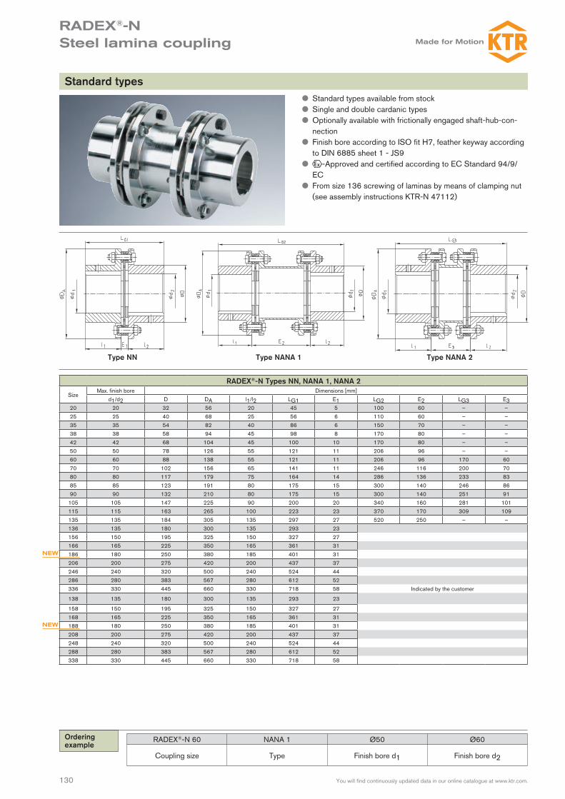
RADEX®-N Types NANA 4, NNZ and NNW
SizeMax. finish bore Dimensions [mm]
d1/d2 D DA l1/l2 LG7 E7 LG8 E820 20 32 56 2025 25 40 68 2535 35 54 82 4038 38 58 94 4542 42 68 104 4550 50 78 126 5560 60 88 138 5570 70 102 156 6580 80 117 179 7585 85 123 191 8090 90 132 210 80
105 105 147 225 90115 115 163 265 100135 135 184 305 135136 135 180 300 135156 150 195 325 150166 165 225 350 165186 180 250 380 185206 200 275 420 200246 240 320 500 240286 280 383 567 280336 330 445 660 300138 135 180 300 135158 150 195 325 150168 165 225 350 165188 180 250 380 185208 200 275 420 200248 240 320 500 240288 280 383 567 280338 330 445 660 300
NEW
NEW
L G7
= E
7 +
l 1 +
l 2
L G8
= E
8 +
l 1 +
l 2
RADEX®-N 60 NANA 4 Ø50 Ø60 2500
Coupling size Type Finish bore d1 Finish bore d2 Shaft distance dimension
z Types as per customer requirements z Type NANA 4 for shaft distance dimensions up to 6 m (please note the critical whirling speed)
z Type NNW with solid shaft (please note the critical whirling speed)
z Finish bore according to ISO fit H7, feather keyway according to DIN 6885 sheet 1 - JS9
z -Approved and certified according to EC Standard 94/9/EC
z From size 136 screwing of laminas by means of clamping nut (see assembly instructions KTR-N 47112)
Type NANA 4 Type NNW
Inte
rmed
iate
sha
ft di
men
sion
acc
ordi
ng to
cus
tom
er s
peci
ficat
ion
nter
med
iate
sha
ft di
men
sion
acc
ordi
ng to
cus
tom
er s
peci
ficat
ion
Customized types
Ordering example:
RA
DE
X®-N
RIG
IFLE
X®-N
RIG
IFLE
X®-H
P
133You will find continuously updated data in our online catalogue at www.ktr.com.
RADEX®-N Steel lamina coupling
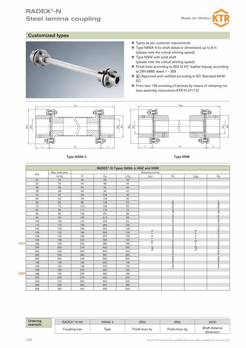
RADEX®-N Type NANA 3
SizeMax. finish bore Dimensions [mm] Perm. displacements
d D DA EStandard 1) l1/l2 Angle each lamina [°] Axial [mm]42 42 68 104 100 45 1,0 2,850 50 78 126 140/180 55 1,0 3,260 60 88 138 100/140/180/250 55 1,0 2,070 70 102 156 100/140/180 65 1,0 2,280 80 117 179 100/140/180/250 75 1,0 2,685 85 123 191 100/140/180/250 80 1,0 2,390 90 132 210 140/180/250 80 1,0 2,0
105 105 147 225 250 90 1,0 2,4115 115 163 265 250 100 1,0 2,8135 135 184 305 250 135 1,0 3,5136 135 180 300 135 0,7 3,7156 150 195 325 150 0,7 4,2166 165 225 350 165 0,7 4,5186 180 250 380 185 0,7 4,8206 200 275 420 200 0,7 5,2246 240 320 500 240 0,7 6,0286 280 383 567 280 0,7 6,7336 330 445 660 330 0,7 7,5138 135 180 300 135 0,5 2,6158 150 195 325 150 0,5 2,8168 165 225 350 165 0,5 3,0188 180 250 380 185 0,5 3,2208 200 275 420 200 0,5 3,5248 240 320 500 240 0,5 4,0288 280 383 567 280 0,5 4,5338 330 445 660 330 0,5 5,0
NEW
NEW
RADEX®-N 60 NANA 3 Ø50 Ø60 140
Coupling size Type Finish bore d1 Finish bore d2 Shaft distance dimension
Standard series NANA 3 for pump drives according to API 610 z Series NANA 3 for pump drives, coupling according to API 610
z High balancing quality due to accurate manufacturing (AGMA class 9)
z Device to protect the spacer if the lamina breaks (see detail “X”) z Finish bore according to ISO fit H7, feather keyway according to DIN 6885 sheet 1 - JS9
z -Approved and certified according to EC Standard 94/9/EC
z From size 136 screwing of laminas by means of clamping nut (see assembly instructions KTR-N 47112)
Safety gear of the spacer:The lamina sets have a sleeve in order to secure the spacer if the lamina breaks.
Detail “X”
1) Other distance dimensions E available on request.
acc. to customer’s specifications
Ordering example:

134 You will find continuously updated data in our online catalogue at www.ktr.com.
RADEX®-N Steel lamina coupling
RADEX®-N Type NANA 4 CFK
SizeTorque [Nm] 1) Dimensions [mm]
TKN TKmax DA d1/d2 max. D l1/l2 E1 DBSE LGes.Composite
tubeR
max. DBSE2)
with 1500 rpm70 800 1600 149 70 102 65 11 95 350085 1800 3600 184 85 123 80 15 117 390090 2500 5000 200 90 135 80 15 128 4100
115 4500 9000 253 115 163 100 23 160 4600l 1 +
l 2 +
D
BS
E
RADEX®-N 85 NANA 4 CFK Ø60 Ø70 3000
Coupling size Type Finish bore d1 Finish bore d2 Shaft distance dimension
Corrosion-resistant type for big shaft distance dimensions z All steel parts made of stainless material z Composite tubes are conglutinated with the flanges and radi-ally bolted in addition
z Spacer sealed against environmental influences (e. g. penetra-tion of moisture into the glued joint)
z On request also available with brake disk made of stainless material
z ATEX release possible
acc.
to
cust
omer
’s
spec
ifica
-tio
ns
1) For selection of coupling see page 123/124. 2) For higher speeds or bigger shaft distance dimensions please consult with KTR’s engineering department (+49 5971 798-484). The above-mentioned characteristic figures (e. g. max. DBSE) can be varied by Composite tubes optimized for the application.
Particularly the steel lamina couplings are well suited for applications with especially large distance dimensions between the drive and the driven side (e. g. cooling towers, ventilators etc.) due to their design. In order to be able to realize high speeds with large distance dimensions, RADEX®-N couplings with intermediate shafts made of glass fiber or carbon fiber reinforced nylon (GRP or CFRP) are used, if necessary.
Ordering example:

RA
DE
X®-N
RIG
IFLE
X®-N
RIG
IFLE
X®-H
P
135
RIGIFLEX®-N Steel lamina coupling
You will find continuously updated data in our online catalogue at www.ktr.com.
Description of coupling
Flange
Lamina set
Special pins
Explosion protection useRIGIFLEX®-N couplings are suitable for the use in drives in hazardous areas. The couplings are certified and confirmed according to EC stand-ard 94/9/EC (ATEX 95) as units of category 2G/2D and thus suitable for the use in hazardous areas of zone 1, 2, 21 and 22. Please read through our information included in the respective Type Examination Certificate and the operating and mounting instructions at www.ktr.com.
Protecting the spacerSince our main idea with the development of RIGIFLEX®-N was to com-ply with the standards of API 610 and API 671, the spacer is secured by a safety catch, too. In case that the laminas break the spacer remains within the coupling. In general the removable part is supplied along with a lamina set preassembled by the manufacturer.
RIGIFLEX®-N laminasRIGILFEX®-N laminas are waisted lamina sets arranged in layers. They are connected to the hubs or flanges, respectively, in an absolutely backlash-free fit by means of positive-locking set screws.The number of the layers of individual laminas allows to vary torques, displacement figures and stiffness for special designs.
RIGIFLEX®-N couplings are used on such applications which require a reliable and maintenance-free torque transmission with shaft displace-ment at the same time.RIGIFLEX®-N was developed specifically for pump drives. This coupling system corresponds to the regulations of API 610 and may be supplied in accordance with API 671 optionally. (API = American Petroleum In-stitute)Torques from 60 Nm to 280.000 Nm are available in 23 sizes for an optimum adjustment to the different applications.
Lamina set Special pins
Safety gear

136
RIGIFLEX®-N Steel lamina coupling
You will find continuously updated data in our online catalogue at www.ktr.com.
SizePermissible angular displacement
0 0,1 0,2 0,3 0,4 0,5 0,6 0,7Permissible axial displacement
35 1,20 1,00 0,85 0,74 0,60 0,40 0,20 0,0050 1,40 1,20 1,00 0,80 0,60 0,40 0,20 0,0065 1,50 1,29 1,07 0,86 0,64 0,43 0,22 0,0075 1,80 1,54 1,29 1,03 0,77 0,52 0,26 0,0085 2,10 1,80 1,50 1,20 0,90 0,60 0,30 0,00
110 2,40 2,06 1,71 1,37 1,03 0,69 0,34 0,00120 2,60 2,23 1,86 1,48 1,11 0,74 0,37 0,00140 3,30 2,83 2,36 1,88 1,41 0,94 0,47 0,00160 3,80 3,26 2,71 2,17 1,63 1,09 0,54 0,00166 3,70 3,17 2,64 2,12 1,59 1,06 0,53 0,00196 4,20 3,60 3,00 2,40 1,80 1,20 0,60 0,00216 4,50 3,86 3,21 2,57 1,93 1,29 0,64 0,00256 5,20 4,46 3,71 2,97 2,23 1,49 0,74 0,00306 6,00 5,14 4,29 3,43 2,57 1,72 0,86 0,00346 6,75 5,79 4,82 3,86 2,89 1,93 0,96 0,00406 7,50 6,43 5,36 4,28 3,21 2,14 1,07 0,00168 2,60 2,08 1,56 1,04 0,52 0,00 – –198 2,80 2,24 1,68 1,12 0,56 0,00 – –218 3,00 2,40 1,80 1,20 0,60 0,00 – –258 3,50 2,80 2,10 1,40 0,70 0,00 – –308 4,00 3,20 2,40 1,60 0,80 0,00 – –348 4,50 3,60 2,70 1,80 0,90 0,00 – –408 5,00 4,00 3,00 2,00 1,00 0,00 – –
Torques and displacements
Size Lamina typeTorques [Nm] Permissible displacements
TKN TK max. TKWAngular
± Kw 1) [°]Axial
± Ka [mm]Radial ± Kr [mm]
E=100 E=140 E=180 E=200 E=25035
4 hole lamina120 240 60 0,7 1,2 0,90 1,40 – – –
50 240 480 120 0,7 1,4 0,77 1,26 – – –65 450 900 225 0,7 1,5 0,75 1,23 1,72 – –75
6 hole
940 1880 470 0,7 1,8 0,73 1,22 1,71 – –85
lamina
1700 3400 850 0,7 2,1 – 1,14 1,62 1,87 2,48110 2700 5400 1350 0,7 2,4 – 1,05 1,54 1,78 2,39120 4500 9000 2250 0,7 2,6 – 1,00 1,49 1,73 2,35140 9000 18000 4500 0,7 3,3 – – – 1,55 2,16160 13000 26000 6500 0,7 3,8 – – – – 1,99166 17500 35000 8750 0,7 3,7
Mounting dimension E as indicated by the customer
196 22500 45000 11250 0,7 4,2216 32000 64000 16000 0,7 4,5256 52500 105000 26250 0,7 5,2306 86000 172000 43000 0,7 6,0346 135000 270000 67500 0,7 6,7406 210000 420000 105000 0,7 7,5168
8 hole
23000 46000 11500 0,5 2,6198
lamina
30000 60000 15000 0,5 2,8218 42500 85000 21500 0,5 3,0258 70000 140000 35000 0,5 3,5308 115000 230000 57500 0,5 4,0348 180000 360000 90000 0,5 4,5408 280000 560000 140000 0,5 5,0
Technical data
The following lamina types are distinguished with RIGIFLEX®-N:
Size 35 – 65 (4 hole lamina)
Size 75 – 160 (6 hole lamina)
Size 166 – 406 (6 hole lamina)
Size 168 – 408 (8 hole lamina)
1) Angular displacement each lamina
If axial, angular and radial shaft displacement arises in parallel please note the following table:

RA
DE
X®-N
RIG
IFLE
X®-N
RIG
IFLE
X®-H
P
137
RIGIFLEX®-N Steel lamina coupling
You will find continuously updated data in our online catalogue at www.ktr.com.
Permissible speeds and stiffness
Size Max. speed [rpm] Each lamina set ct [Nm/rad] for complete coupling with mounting length Ecw [Nm/rad] ct [Nm/rad] E=100 E=140 E=180 E=200 E=250
35 23000 107 170000 65020 56700 – – –50 18000 470 198000 73953 63990 – – –65 13600 860 360000 146022 129938 117046 – –75 12400 1500 720000 306145 278381 255234 – –85 11000 2300 1062000 – 406641 369429 353265 318433
110 9000 2800 1460000 – 664284 637587 625028 595693120 8000 4100 4500000 – 1798018 1637553 1567602 1416348140 6400 6400 5600000 – – – 2363340 2226630160 5600 9800 6850000 – – – – 2654894166 5600 10200 7640000
Mounting dimension E as indicated by the customer
196 5200 17130 9200000216 4600 32300 13800000256 3900 47060 23800000306 3300 64700 28400000346 2900 85300 41400000406 2500 161000 48500000168 5600 34000 13200000198 5200 58000 18300000218 4600 110000 26200000258 3900 160000 52000000308 3300 220000 71000000348 2900 290000 108000000408 2500 550000 156000000
Weights and mass moments of inertia
SizeHub (max. bore) Spacer complete [kg] Spacer complete [x10³ kgm2]
[kg] [kgm2] E=100 E=140 E=180 E=200 E=250 E=100 E=140 E=180 E=200 E=25035 0,60 0,0007 1,030 1,120 – – – 0,00040 0,00050 – – –50 0,92 0,001019 2,262 2,442 – – – 0,00256 0,00263 – – –65 2,7 0,00541 3,922 4,183 4,445 – – 0,00810 0,00830 0,00828 – –75 2,4 0,00566 4,482 4,842 5,202 – – 0,01143 0,01191 0,01239 – –85 3,7 0,01135 – 7,154 7,548 7,746 8,239 – 0,02364 0,02427 0,02459 0,02538
110 6,7 0,03222 – 12,492 13,478 13,972 15,205 – 0,06291 0,06540 0,06665 0,06976120 9,2 0,05238 – – 17,324 17,842 19,137 – – 0,10314 0,10458 0,10818140 18,2 0,15175 – – – 32,530 34,325 – – – 0,31901 0,32845160 29,9 0,33890 – – – – 52,458 – – – – 0,68640166 28,0 0,32
Mounting dimension E as indicated by the customer
196 37,0 0,554216 50,0 0,85256 95,0 2,35306 138,0 4,55346 215,0 9,75406 310,0 18,95168 30,0 0,33198 40,0 0,56218 52,0 0,88258 99,0 2,43308 142,0 4,78348 222,0 9,83408 325,0 19,22
Technical data
cw = angular stiffnessct = torsion spring stiffness

138
RIGIFLEX®-N Steel lamina coupling
You will find continuously updated data in our online catalogue at www.ktr.com.
RIGIFLEX®-N Type A
SizeTorque [Nm] Max. finish bore Dimensions [mm] Screws DIN EN ISO 4762
TKN TK max. TKW d1/d2 D DA l1/l2 l3 G t1 t2 E1 E 1) Mxl TA [Nm]35 120 240 60 50 – 75 38,5 8,5 M6 15 – 6 100 140 – – – M4x45 4,150 240 480 120 50 70 95 50 12 M6 10 – 9 100 140 – – – M6x22 1465 450 900 225 65 100 126 63 12 M8 20 – 11 100 140 180 – – M6x25 1475 940 1880 470 75 105 138 62,5 12 M8 20 – 11 100 140 180 – – M8x30 3585 1700 3400 850 85 120 156 72,5 15 M10 20 – 12 – 140 180 200 250 M8x30 35
110 2700 5400 1350 110 152 191 87 18 M10 25 – 12 – 140 180 200 250 M10x35 69120 4500 9000 2250 120 165 213 102 20 M12 25 – 12 – – 180 200 250 M12x40 120140 9000 18000 4500 140 200 265 126 25 M12 30 – 15 – – – 200 250 M16x50 295160 13000 26000 6500 160 230 305 145 31 M12 30 – 15 – – – – 250 M16x55 295166 17500 35000 8750 160 230 305 155 31 M16 30 70 17
acc. to customer’s request
M20x50 560196 22500 45000 11250 190 260 330 185 32 M16 40 90 24 M20x50 560216 32000 64000 16000 210 285 370 205 32 M20 50 110 26 M20x65 560256 52500 105000 26250 250 350 440 245 38 M20 70 130 31 M24x80 970306 86000 172000 43000 300 400 515 295 43 M24 70 130 36 M27x100 1450346 135000 270000 67500 340 460 590 335 55 M24 95 175 45 M30x110 1950406 210000 420000 105000 400 530 675 395 58,5 M24 95 175 50 M36x130 3300168 23000 46000 11500 160 230 305 155 31 M16 30 70 17 M20x50 560198 30000 60000 15000 190 260 330 185 32 M16 40 90 24 M20x50 560218 42500 85000 21500 210 285 370 205 32 M20 50 110 26 M20x65 560258 70000 140000 35000 250 350 440 245 38 M20 70 130 31 M24x80 970308 115000 230000 57500 300 400 515 295 43 M24 70 130 36 M27x100 1450348 180000 360000 90000 340 460 590 335 55 M24 95 175 45 M30x110 1950408 280000 560000 140000 400 530 675 395 58,5 M24 95 175 50 M36x130 3300
RIGIFLEX®-N 120 A Ø 100 Ø 120 200
Coupling size Type Bore d1 Bore d2Shaft distance dimension E
Type A
Ordering example:
Size 50 - 408Size 35
1) Other shaft distance dimensions available on request. For selection of coupling see page 123/124. Mounting instrucitons No. 47410 available at www.ktr.com.
z Series for pump drives z Coupling in accordance with API 610, API 671 optionally. z Available with large hub for bigger bore diameters z Spacers are supplied assembled by the manufacturer z Finish bore according to ISO fit H7, feather key according to DIN 6885 sheet 1 - JS9
z High balancing quality due to accurate machining (AGMA Class 9)
z -Approved and certified according to EC Standard 94/9/EC
RA
DE
X®-N
RIG
IFLE
X®-N
RIG
IFLE
X®-H
P
139You will find continuously updated data in our online catalogue at www.ktr.com.
RIGIFLEX®-HP High-performance steel lamina coupling
Application Operating performance Operating factor SBTurbines Continuous torque 1,5
Centrifugal compressors Continuous torque 1,5
Tank feed pumps Continuous torque 1,5
API 671 Continuous torque 1,5
Large blowers Low torque fluctuations 2
Screw compressors Low torque fluctuations 2
Piston compressors / Piston pumps Average to high torque fluctuations 2,5 - 3
Coupling selection of RIGIFLEX®-HP
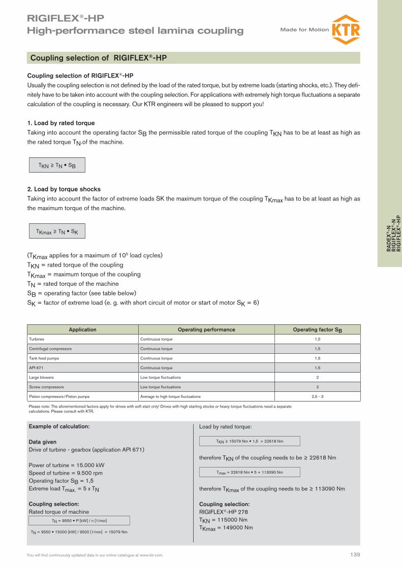
Coupling selection of RIGIFLEX®-HPUsually the coupling selection is not defined by the load of the rated torque, but by extreme loads (starting shocks, etc.). They defi-nitely have to be taken into account with the coupling selection. For applications with extremely high torque fluctuations a separate calculation of the coupling is necessary. Our KTR engineers will be pleased to support you!
1. Load by rated torque Taking into account the operating factor SB the permissible rated torque of the coupling TKN has to be at least as high as the rated torque TN.of the machine.
TKN ≥ TN SB
2. Load by torque shocks Taking into account the factor of extreme loads SK the maximum torque of the coupling TKmax has to be at least as high as the maximum torque of the machine.
TKmax ≥ TN SK
(TKmax applies for a maximum of 105 load cycles)TKN = rated torque of the couplingTKmax = maximum torque of the coupling TN = rated torque of the machine SB = operating factor (see table below) SK = factor of extreme load (e. g. with short circuit of motor or start of motor SK = 6)
Please note: The aforementioned factors apply for drives with soft start only! Drives with high starting stocks or heavy torque fluctuations need a separate calculations. Please consult with KTR.
Example of calculation:
Data givenDrive of turbine - gearbox (application API 671)
Power of turbine = 15.000 kWSpeed of turbine = 9.500 rpmOperating factor SB = 1,5Extreme load Tmax. = 5 x TN
Coupling selection:Rated torque of machine
TN = 9550 15000 [kW] / 9500 [1/min] = 15079 Nm
TN = 9550 P [kW] / n [1/min]
Load by rated torque:
therefore TKN of the coupling needs to be ≥ 22618 Nm
therefore TKmax of the coupling needs to be ≥ 113090 Nm
Coupling selection:RIGIFLEX®-HP 278TKN = 115000 NmTKmax = 149000 Nm
TKN ≥ 15079 Nm 1,5 = 22618 Nm
Tmax = 22618 Nm 5 = 113090 Nm
140 You will find continuously updated data in our online catalogue at www.ktr.com.
RIGIFLEX®-HP High-performance steel lamina coupling
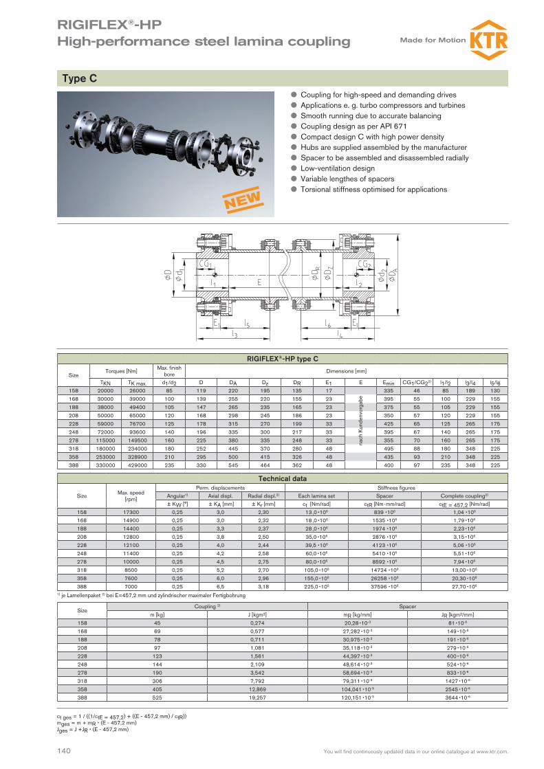
RIGIFLEX®-HP type C
SizeTorques [Nm] Max. finish
bore Dimensions [mm]
TKN TK max. d1/d2 D DA Dz DR E1 E Emin CG1/CG22) l1/l2 l3/l4 l5/l6158 20000 26000 85 119 220 195 135 17 335 46 85 189 130168 30000 39000 100 139 255 220 155 23 395 55 100 229 155188 38000 49400 105 147 265 235 165 23 375 55 105 229 155208 50000 65000 120 168 298 245 186 23 350 57 120 229 155228 59000 76700 125 178 315 270 199 33 425 65 125 265 175248 72000 93600 140 196 335 300 217 33 395 67 140 265 175278 115000 149500 160 225 380 335 248 33 355 70 160 265 175318 180000 234000 180 252 445 370 280 48 495 88 180 348 225358 253000 328900 210 295 500 415 326 48 435 93 210 348 225388 330000 429000 235 330 545 464 362 48 400 97 235 348 225
Technical data
Size Max. speed [rpm]
Perm. displacements Stiffness figures Angular1) Axial displ. Radial displ.2) Each lamina set Spacer Complete coupling2)
± KW [°] ± KA [mm] ± Kr [mm] ct [Nm/rad] ctR [Nm · mm/rad] ctE = 457,2 [Nm/rad]158 17300 0,25 3,0 2,30 13 ,0 106 839 106 1,04 106
168 14900 0,25 3,0 2,32 18 ,0 106 1535 106 1,79 106
188 14400 0,25 3,3 2,37 28 ,0 106 1974 106 2,23 106
208 12800 0,25 3,8 2,50 35,0 106 2876 106 3,15 106
228 12100 0,25 4,0 2,44 39,5 106 4123 106 5,06 106
248 11400 0,25 4,2 2,58 60,0 106 5410 106 5,51 106
278 10000 0,25 4,5 2,75 80,0 106 8592 106 7,94 106
318 8500 0,25 5,2 2,70 105,0 106 14724 106 13,00 106
358 7600 0,25 6,0 2,96 155,0 106 26258 106 20,30 106
388 7000 0,25 6,5 3,18 225,0 106 37596 106 27,70 106
SizeCoupling 2) Spacer
m [kg] J [kgm²] mR [kg/mm] JR [kgm²/mm]158 45 0,274 20,28 10-3 81 10-6
168 69 0,577 27,282 10-3 149 10-6
188 78 0,711 30,975 10-3 191 10-6
208 97 1,081 35,118 10-3 279 10-6
228 123 1,561 44,397 10-3 400 10-6
248 144 2,109 48,614 10-3 524 10-6
278 190 3,542 58,694 10-3 833 10-6
318 306 7,792 79,311 10-3 1427 10-6
358 405 12,869 104,041 10-3 2545 10-6
388 525 19,257 120,151 10-3 3644 10-6
NEW
Type C z Coupling for high-speed and demanding drives z Applications e. g. turbo compressors and turbines z Smooth running due to accurate balancing z Coupling design as per API 671 z Compact design C with high power density z Hubs are supplied assembled by the manufacturer z Spacer to be assembled and disassembled radially z Low-ventilation design z Variable lengthes of spacers z Torsional stiffness optimised for applications
nach
Kun
denv
orga
be
1) je Lamellenpaket 2) bei E=457,2 mm und zylindrischer maximaler Fertigbohrung
ct ges = 1 / ((1/ctE = 457,2) + ((E - 457,2 mm) / ctR))mges = m + mR (E - 457,2 mm)Jges = J +JR (E - 457,2 mm)

RA
DE
X®-N
RIG
IFLE
X®-N
RIG
IFLE
X®-H
P
141You will find continuously updated data in our online catalogue at www.ktr.com.
RIGIFLEX®-HP High-performance steel lamina coupling
RIGIFLEX®-HP Bauart L
SizeTorques [Nm] Max. finish
bore Dimensions [mm]
TKN TK max. d1/d2 D DA Dz DR E1 E Emin CG1/CG22) l1/l2 l3/l4 l5/l6158 20000 26000 150 210 310 220 135 17 265 140 150 163,5 37,5168 30000 39000 165 230 320 255 155 23 340 148 165 168,5 48,0188 38000 49400 180 250 335 265 165 23 340 156 180 183,5 48,0208 50000 65000 200 280 362 298 186 23 340 165 200 203,5 48,0228 59000 76700 220 310 390 315 199 33 390 179 220 223,5 54,5248 72000 93600 240 340 420 334 217 33 390 185 235 238,5 54,5278 115000 149500 270 380 455 380 248 33 390 202 270 273,5 54,5318 180000 234000 315 445 550 445 280 48 510 246 315 318,5 71,5358 253000 328900 350 490 600 500 326 48 510 263 350 353,5 71,5388 330000 429000 380 535 650 545 362 48 510 277 380 383,5 71,5
RIGIFLEX®-HP 188 L Ø 160 Ø 180 457,2
Coupling size Type Bore d1 Bore d2Shaft distance dimen-
sion E
Technical data
Size Max. speed [rpm]
Perm. displacements Stiffness figures Angular1) Axial displ. Radial displ.2) Each lamina set Spacer Complete coupling2)
± KW [°] ± KA [mm] ± Kr [mm] ct [Nm/rad] ctR [Nm · mm/rad] ctE = 457,2 [Nm/rad]158 13800 0,25 3,0 1,56 13,0 106 839 106 1,70 106
168 12300 0,25 3,0 1,45 18,0 106 1535 106 3,00 106
188 11400 0,25 3,3 1,45 28,0 106 1974 106 4,08 106
208 10500 0,25 3,8 1,45 35,0 106 2876 106 5,61 106
228 9700 0,25 4,0 1,34 39,5 106 4123 106 7,77 106
248 9000 0,25 4,2 1,34 60,0 106 5410 106 10,70 106
278 8300 0,25 4,5 1,34 80,0 106 8592 106 15,60 106
318 6900 0,25 5,2 1,13 105,0 106 14724 106 26,90 106
358 6300 0,25 6,0 1,13 155,0 106 26258 106 41,20 106
388 5800 0,25 6,5 1,13 225,0 106 37596 106 61,30 106
SizeCoupling 2) Spacer
m [kg] J [kgm²] mR [kg/mm] JR [kgm²/mm]158 80 0,717 20,28 10-3 8110-6
168 115 1,327 27,282 10-3 149 10-6
188 135 1,759 30,975 10-3 191 10-6
208 175 2,771 35,118 10-3 279 10-6
228 235 4,525 44,397 10-3 400 10-6
248 285 6,417 48,614 10-3 524 10-6
278 375 10,381 58,694 10-3 833 10-6
318 642 24,810 79,311 10-3 1427 10-6
358 812 38,404 104,041 10-3 2545 10-6
388 1016 57,062 120,151 10-3 3644 10-6
as re
ques
ted
by th
e cu
stom
er
NEW
1) each lamina set, 2) with E=457,2 mm and max. cylindrical finish bore
Ordering example:
z Coupling for high-speed and demanding drives z Applications e. g. on turbo compressors and turbines z Smooth running due to accurate balancing z Coupling design as per API 671 z Design L for large shaft diameters z Spacers supplied assembled by the manufacturer z Spacer to be assembled and disassembled radially z Low-ventilation design z Variable lengthes of spacers z Torsional stiffness optimised for applications
Type L
142 You will find continuously updated data in our online catalogue at www.ktr.com.
RIGIFLEX®-HP High-performance steel lamina coupling
Technical description of RIGIFLEX®-HP
Balancing:Usually RIGIFLEX®-HP - couplings are balanced according to the balancing methods recommended in API 671. The usual methods are as follows:
z Balancing of individual components z Summation balancing for verifying the balancing of individual components. It has to be made sure that adjustments may be performed on individual components only.
z Summation balancing with amendment of the balancing quality on the complete coupling. z It goes without saying that different balancing methods are possible as defined by the customer.
Axial natural frequency:With the coupling selection the axial natural frequency has to be reviewed (critical speed). According to API 671 the critical speed should be +_ 10% beyond one time and two times the operating speed of the drive. .
Screwing during transport and mounting: For balancing, transporting and mounting of the coupling the lamina sets are firmly clamped axially via transport screws and distance washers (to protect the lamina sets from damaging). Please note: Before the coupling is set into operation it is absolutely necessary to remove the screwings!
Axial pre-stress of lamina sets: If modifications of the shaft distance dimension (e. g. caused by heat expansion) have to be expected, the lamina sets can be axially prestressed. As a result the coupling operates in neutral position (zero position) of the lamina sets during normal operation.
Spacer disks for couplings with taper bores:With the use of taper shafts the shaft distance dimension may lightly vary due to displacement. To compensate for spacer disks are added to the coupling on request. The disks are mounted on site, if necessary.
Shaft-hub-connections:Usually RIGIFLEX®-HP is supplied with taper bores for an oil press fit. As an alternative feather key connections, flange con-nections or mechanical clamping connections, e. g. via KTR CLAMPEX® clamping sets, are available.
Delivery condition:Depending on the customer’s request, the RIGIFLEX®-HP couplings can be delivered either fully assembled or as individual assemblies. The lamina sets are basically assembled and may only be disassembled on consultation with the manufacturer.
Mounting instructions:See: www.ktr.com