Embed Size (px)
Citation preview

Rigging and Assembly Instructionsfor Crossflow Cooling Towers
INTRODUCTIONFXT, Series 1500 and 3000 Cooling Towers should be rigged and assembled as outlined in this bulletin. Theseprocedures should be thoroughly reviewed prior to the actual rigging and assembly of the equipment to acquaint allpersonnel with procedures to be followed and to assure that all necessary equipment will be available beforehand.
BBee ssuurree ttoo hhaavvee aa ccooppyy ooff tthhee cceerrttiiffiieedd ddrraawwiinngg aavvaaiillaabbllee ffoorr rreeffeerreennccee.. IIff yyoouu ddoo nnoott hhaavvee aa ccooppyy ooff tthhiiss ddrraawwiinngg,, oorr iiffyyoouu nneeeedd aaddddiittiioonnaall iinnffoorrmmaattiioonn aabboouutt tthhiiss uunniitt,, ccoonnttaacctt yyoouurr llooccaall BBAACC RReepprreesseennttaattiivvee wwhhoossee nnaammee aanndd tteelleepphhoonnee nnuummbbeerr aarree oonn aa llaabbeell aaddjjaacceenntt ttoo tthhee aacccceessss ddoooorr.. TThhee mmooddeell nnuummbbeerr aanndd sseerriiaall nnuummbbeerr ooff tthhee uunniitt aarree aallssoo llooccaatteedd iinn tthhiiss aarreeaa..
ShippingBAC Cooling Towers are factory assembled to assure uniform quality and minimum field assembly. For the dimensions and weights of a specific unit or section, refer to the certified drawings.
Table 1: Shipping
1R244/1-OI
PPrroodduucctt LLiinnee MMooddeellss tthhaatt sshhiipp iinn oonnee sseeccttiioonn MMooddeellss tthhaatt sshhiipp iinn ttwwoo sseeccttiioonnss
FXTAll single cells ship fully assembled
FXT-6 thru FXT-257
All multi-cell FXT-230, 260 thru FXT-514
Series 1500 15146 thru 15177, 15201 and 15219
Due to shipping height restrictions15200, 15227 thru 15282, and
15296 thru 15425
Series 3000 3240C thru 3672C and 3583C thru 3725C
Due to shipping height restrictions3728C thru 31056C and 31132C thru 31301C
Check Unit Before RiggingWhen the unit is delivered to the jobsite, it should be checked thoroughly to ensure all required items have beenreceived and are free of any shipping damage prior to signing the bill of lading. The following parts should beinspected:� Sheaves and Belts� Bearings � Bearing Supports� Fan Motor(s)� Fan(s) and Fan Shaft(s)� Float Valve Assembly(s)� Water Distribution System� Hot Water Basin Integral Strainer (Series 1500)� Fill� Cold Water Basin Strainer(s)� Interior Surfaces� Exterior Surfaces� Optional EASY CONNECT® Piping Arrangement (Series 3000)� Louvers� Air Inlet Screens or Combined Inlet Shields (when provided)� Miscellaneous Items:All bolts, nuts, washers, and sealer tape required to assemble sections or component parts are furnished by BACand shipped with the unit. A checklist inside the envelope attached to the side of the unit marked “Contractor’s Installation Instructions” indicates what miscellaneous parts are included with the shipment and where they are packed.
Unit WeightsBefore rigging any unit, the weight of each section should be verified from the unit certified drawing. Some accessories add additional weight as shown on the respective accessory drawings.
WWAARRNNIINNGG:: BBeeffoorree aann aaccttuuaall lliifftt iiss uunnddeerrttaakkeenn,, eennssuurree tthhaatt nnoo wwaatteerr,, ssnnooww,, iiccee,, oorr ddeebbrriiss hhaass ccoolllleecctteedd iinn tthheebbaassiinn oorr eellsseewwhheerree iinn tthhee uunniitt.. SSuucchh aaccccuummuullaattiioonnss wwiillll aadddd ssuubbssttaannttiiaallllyy ttoo tthhee eeqquuiippmmeenntt’’ss lliiffttiinngg wweeiigghhtt..
WWAARRNNIINNGG:: IInn tthhee eevveenntt ooff eexxtteennddeedd lliiffttss oorr wwhheerree hhaazzaarrddss eexxiisstt,, tthhee lliiffttiinngg ddeevviicceess sshhoouulldd bbee uusseedd iinn ccoonnjjuunnccttiioonn wwiitthh ssaaffeettyy sslliinnggss ppllaacceedd uunnddeerr tthhee uunniitt..
Anchoring7/8” diameter holes for Series 3000 and Series 1500, and 5/8” diameter holes for FXT Cooling Towers are providedin the bottom flange of the basin section for bolting the unit to the support beams. Refer to the suggested supportlocation drawing included in the submittal for location and quantity of the mounting holes. The unit must be levelfor proper operation. Anchor bolts must be provided by others.
SafetyAdequate precautions appropriate for the installation and location of these products should be taken to safeguardthe equipment and the premises from damage and the public from possible injury.
WWAARRNNIINNGG:: WWhheenn tthhee ffaann ssppeeeedd ooff tthhee uunniitt iiss ttoo bbee cchhaannggeedd ffrroomm tthhee ffaaccttoorryy sseett ssppeeeedd,, iinncclluuddiinngg tthhee uussee ooff aavvaarriiaabbllee ssppeeeedd ddeevviiccee,, sstteeppss mmuusstt bbee ttaakkeenn ttoo aavvooiidd ooppeerraattiinngg aatt oorr nneeaarr tthhee ffaann’’ss ““ccrriittiiccaall ssppeeeedd”” wwhhiicchh ccoouullddrreessuulltt iinn ffaann ffaaiilluurree aanndd ppoossssiibbllee iinnjjuurryy oorr ddaammaaggee.. CCoonnssuulltt wwiitthh yyoouurr llooccaall BBAACC RReepprreesseennttaattiivvee oonn aannyy ssuucchhaapppplliiccaattiioonnss..
WWAARRNNIINNGG:: OOnnllyy ppeerrssoonnnneell qquuaalliiffiieedd ttoo ddoo ssoo sshhoouulldd uunnddeerrttaakkee ooppeerraattiioonn,, mmaaiinntteennaannccee aanndd rreeppaaiirr ooff tthhiisseeqquuiippmmeenntt.. PPrrooppeerr ccaarree,, pprroocceedduurreess aanndd ttoooollss mmuusstt bbee uusseedd iinn hhaannddlliinngg,, lliiffttiinngg,, iinnssttaalllliinngg,, ooppeerraattiinngg,, mmaaiinnttaaiinniinngg aanndd rreeppaaiirriinngg tthhiiss eeqquuiippmmeenntt ttoo pprreevveenntt ppeerrssoonnaall iinnjjuurryy aanndd//oorr pprrooppeerrttyy ddaammaaggee..
2

Freeze ProtectionThese products must be protected by mechanical and operational methods against damage and/or reduced effec-tiveness due to possible freeze-up. Please refer to the Product and Applications Handbook, Operation andMaintenance Manual, or contact your local BAC Representative for recommended protection alternatives.
LocationAll evaporative cooling equipment must be located to ensure an adequate supply of fresh air to the fans. Whenunits are located adjacent to walls or in enclosures, care must be taken to ensure the warm, saturated, dischargeair is not deflected and short-circuited back to the air intakes.
CCAAUUTTIIOONN:: EEaacchh uunniitt mmuusstt bbee llooccaatteedd aanndd ppoossiittiioonneedd ttoo pprreevveenntt tthhee iinnttrroodduuccttiioonn ooff ddiisscchhaarrggee aaiirr iinnttoo tthhee vveennttiillaattiioonnssyysstteemmss ooff tthhee bbuuiillddiinngg oonn wwhhiicchh tthhee uunniitt iiss llooccaatteedd aanndd ooff aaddjjaacceenntt bbuuiillddiinnggss. For detailed recommendations onBAC equipment layout, see our website at www.BaltimoreAircoil.com or contact your local BAC Representative.
WarrantiesPlease refer to the Limitation of Warranties applicable to and in effect at the time of the sale/purchase of theseproducts.
RIGGINGRefer to Table 2 and Figures 1 through 6 for the recommended minimum size of the spreader bar and the recommended vertical dimension “H” from the lifting device at the base of each unit or section to the spreader bar.In the event of extended lifts or where hazards exist, the lifting devices should be used in conjunction with safetyslings placed under the unit.
Table 2:
Model Number Dimensions (for each cell)Section Min. H Min. W
FXT
Figu
res
1 &
2 66 ttoo 4477 11--SSeeccttiioonn 66’’ NN//AA
5588 ttoo 9955 11--SSeeccttiioonn 88’’ NN//AA
111155 ttoo 225577226600 ttoo 551144
11--SSeeccttiioonn22--SSeeccttiioonn 1122’’ NN//AA
1500 Fi
gure
3
1155114466 ttoo 1155117777,, 1155220011,,1155221199
11--SSeeccttiioonn 1122’’ WW11==1122’’
Figu
re 4 1155220000,,1155222277 ttoo 1155228822 UUppppeerrLLoowweerr
1155’’88’’
WW22==66’’,, WW33==1122’’WW11==1122’’
1155229966 ttoo 1155442255UUppppeerrLLoowweerr
1177’’1111’’
WW22==66’’,, WW33==1122’’WW11==1122’’
3000
Figu
re 5
33224400CC ttoo 33337799CC 11--SSeeccttiioonn 1155’’ 88’’ 66””
33441122CC ttoo 33552277CC 11--SSeeccttiioonn 1177’’ 1100’’
33447733CC ttoo 33550011CC,, 33555522CC33660044CC,, 33664488CC,, 33667722CC
11--SSeeccttiioonn 1188’’ 1122’’
33558833CC,, 33661188CC,, 33667766CC,, 33772255CC 11--SSeeccttiioonn 2200’’ 1144’’
Figu
re 6
33772288CC ttoo 33882288CC UUppppeerrLLoowweerr
1188’’1188’’
1122’’1122’’
33887722CC ttoo 33997700CC UUppppeerrLLoowweerr
1188’’1188’’
1122’’1122’’
33998855CC ttoo 3311005566CC UUppppeerrLLoowweerr
1188’’1188’’
1122’’1122’’
3311113322CCUUppppeerrLLoowweerr
2200’’2200’’
1144’’1144’’
3311221133CC ttoo 3311330011CC UUppppeerrLLoowweerr
2200’’2200’’
1144’’1144’’
3

Figure 1 shows the proper rigging of an FXT Cooling Tower for installation. FXT Cooling Towers may be hoistedshort distances by using the lifting devices provided at the top of each unit as shown in Figure 2.
Figures 1 and 2
4
LIFTING CABLES
LIFTING DEVICES
SPREADER BARS
SAFETY SLINGS
H
FIGURE 1
FIGURE 2
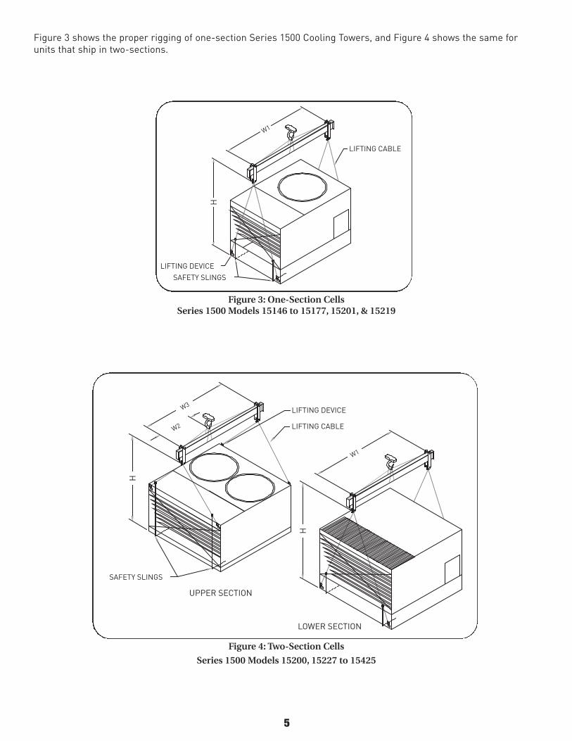
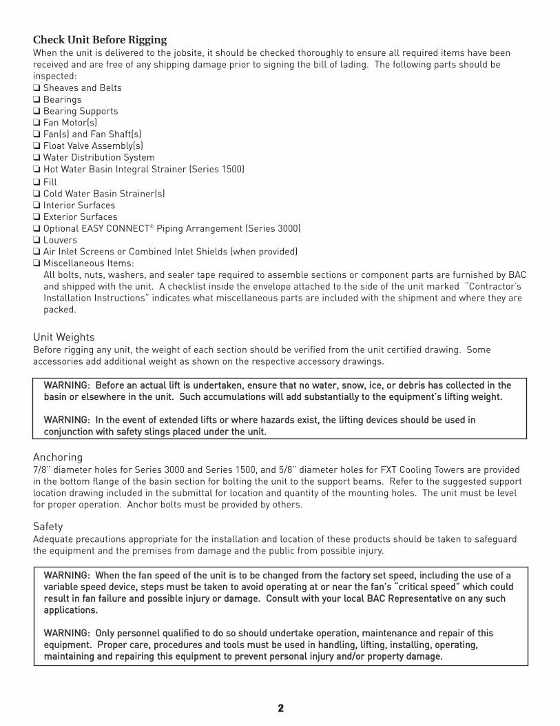
Figure 3 shows the proper rigging of one-section Series 1500 Cooling Towers, and Figure 4 shows the same forunits that ship in two-sections.
Figure 3: One-Section CellsSeries 1500 Models 15146 to 15177, 15201, & 15219
Figure 4: Two-Section Cells
Series 1500 Models 15200, 15227 to 15425
5
W1
LIFTING CABLE
LIFTING DEVICE
SAFETY SLINGS
H
W3
W2
W1
LIFTING DEVICE
LIFTING CABLE
SAFETY SLINGS
UPPER SECTION
LOWER SECTION
H
H
W1
LIFTING CABLE
LIFTING DEVICE
SAFETY SLINGS
H
W3
W2
W1
LIFTING DEVICE
LIFTING CABLE
SAFETY SLINGS
UPPER SECTION
LOWER SECTION
H
H

6
H
UPPERSECTION
SPREADER BAR
(MIN)
W
LIFTING CABLE
SAFETYSLINGS
LIFTING DEVICE FORTHIS SECTION ONLY
(MIN)
W
SPREADER BAR
LIFTING CABLE
LOWERSECTION
H
SAFETYSLINGS
LIFTING DEVICE FORTHIS SECTION ONLYDO NOT USE FORFINAL POSITIONING OFASSEMBLED CELL
H
UPPERSECTION
(MIN)
W
LIFTING CABLE
SAFETYSLINGS
LIFTING DEVICE FORTHIS SECTION ONLY
(MIN)
W
SPREADER BAR
LIFTING CABLE
LOWERSECTION
H
SAFETYSLINGS
LIFTING DEVICE FORTHIS SECTION ONLYDO NOT USE FORFINAL POSITIONING OFASSEMBLED CELL
Figure 5 shows the proper rigging of either a Series 3000 that ships in one-section or the top section of a Series3000 that ships in two-sections. Figure 6 shows the proper rigging of the bottom section of a two-section unit.
Figure 5: Series 3000 One-Section Cells orUpper Section for Two-Section Cells
Figure 6: Series 3000 Bottom Section ofTwo-Section Cells
Notes: All single-cell and multi-cell units must be rigged one section at a time. All FXT-6 to FXT-257 CoolingTowers ship in one-section. Series 1500 Cooling Tower models 15146 to 15177, 15201, and 15219 ship in one-section per cell. Series 3000 Cooling Tower models 3240C to 3672C and 3583C to 3725C ship in one-section percell. All other models ship in two-sections per cell.
DRIFT PIN GUIDES
SPREADER BAR

SECTION ASSEMBLYSeries 1500 and Series 3000 Cooling Towers
To assemble a two-section unit, position the bottom section on the tower support and bolt in place. Install sealertape on the mating flange of the bottom section to ensure an airtight seal between the top and bottom section.Using drift pins in the bolt holes provided, guide the top section onto the bottom section. Match marks must line upas shown in Figure 7a. Bolt in place as illustrated in Figure 7a, Detail “A". Series 1500 towers use 5/16” self-tapping screws. Series 3000 towers use a 1/2” bolt and flat washer. In addition, a seal washer should be usedunder each nut to prevent water leakage.
Note: On multi-cell installations, for Series 1500, it is suggested that cells subsequent to the first, have the top andbottom sections assembled on the support foundation adjacent to the final mounting locations. This will allowspace for securing the top and bottom sections of each cell. Slide the subsequent cell(s) to their final positionusing the lifting devices at the base of the cell(s). Refer to the “Assembly of Multiple-Cell Units” section for details.All multi-cell units have the cell number and “face” identified on each section as well as match marks to show howthe cells are to be mated.
Note: On multi-cell installations for the Series 3000, position the bottom sections on the tower support and bolt inplace. Install foam tape on the mating flanges of the bottom section to ensure an airtight seal between the top andbottom section. Using drift pins in the drift pin guides provided (shown in Figure 7b), guide the top section on to thebottom sections. Match marks must line up as shown in Figure 7a. Bolt the top section onto the bottom section atthe alternate locations as shown in Figure 7a Detail, “A” and Figure 7c. Series 3000 towers use a 1/2” bolt and flatwasher. In addition, a seal washer should be used under each nut to prevent water leakage.
7
MATCHMARKS
SEE NOTE (1)
SEALERTAPE-INSTALLEDIN THE FIELD
SEALWASHER& NUT
DETAIL "A"SERIES 3000: BOLT AND FLAT WASHERSERIES 1500: SELF-TAPPING SCREWS
Figure 7a: Upper and Lower Assembly for Series 1500 andSeries 3000 Cooling Towers
Figure 7c: Alternate Bolting Channels
Figure 7b: Upper and Lower Assembly for Series 3000 Cooling Towers - Alternate Bolting Location
Drift Pin Guides
Alternate Bolting Channels
Note (1): 5/16” Self-TappingScrews for Series 1500, 1/2”Bolt & Flat Washer for Series3000

ASSEMBLY OF MULTI-CELL TOWERSFXT Cooling Towers
Multi-cell FXT’s (Models FXT-230, 260, 272, 320, 350, 384, 432, 480, and 514) are furnished with a flume box toequalize the water level in the cold water basin of each cell.
1. Cell #1 will ship with the flume box factory installed. Position Cell #1 on tower support and bolt in place.
2. Wipe down the flanges on the end of the flume box. Apply a layer of 1/8” x 1” butyl sealer tape around the faceof the flange over the centerline of the holes. Do not overlap or stretch too thinly at the corners. When it isnecessary to splice the sealer, be sure to press the two ends together to form a smooth, continuous strip.Apply a second layer of sealer tape over the first layer following the same procedure. Refer to Figure 8.
3. Position Cell #2 on the tower supports and wipe down the surface adjacent to the opening to remove any dirtor moisture.
4. Using drift pins to assure alignment, draw Cell #2 tight against the flume box.
5. As illustrated in Figure 9, insert tappers in each hole and tighten.
Figure 8: Application of Sealer
Figure 9: Elevation View
8
FLUME BOX
FLUME BOX
FLUME BOX(FACTORY INSTALLED ON CELL #1)
CELL #1
CELL #2
FLANGED END OFFLUME BOX
OVERLAP SEALERTAPE AT CORNERS
APPLY SEALER TAPE BETWEENCENTER LINE OF BOLT HOLESAND OUTER EDGE OF FLANGES
APPLICATION OF SEALERFIGURE 3
ELEVATION VIEWFIGURE 4
SEALERTAPE
CELL #2CELL #1
TAPPERSBOLT &NUT
BASINOPENING
FLUME BOX
FLUME BOX
FLUME BOX
FLUME BOX(FACTORY INSTALLED ON CELL #1)
CELL #1
CELL #2
FLANGED END OFFLUME BOX
OVERLAP SEALERTAPE AT CORNERS
APPLY SEALER TAPE BETWEENCENTER LINE OF BOLT HOLESAND OUTER EDGE OF FLANGES
APPLICATION OF SEALERFIGURE 3
ELEVATION VIEWFIGURE 4
SEALERTAPE
CELL #2CELL #1
TAPPERSBOLT &NUT
BASINOPENING
FLUME BOX

SSeerriieess 11550000 aanndd SSeerriieess 33000000 CCoooolliinngg TToowweerrssRefer to the unit certified print for the proper orientation of each cell. The cell number and “face” are stenciled onthe outer basin wall. Multi-cell cooling tower installations may employ flume boxes to equalize the water level inthe basin of each cell. Follow directions below for details on their installation.
Series 1500 Flume Box Installation
1. Position Cell #1 on the unit support and bolt in place.
2. Wipe down the mating surface by the flume opening to remove any dirt or moisture that may have accumulatedduring shipment.
3. Wipe down the flanges on both ends of the flume box. On one end, apply a layer of 1/8” x 1” butyl sealer tapearound the face of the flange over the centerline of the holes. Do not overlap or stretch too thinly at the cor-ners. When it is necessary to splice the sealer, be sure to press the two ends together to form a smooth, con-tinuous strip. Apply a second layer of sealer tape over the first layer following the same procedure. Refer toFigure 10.
4. Using drift pins to align the bolt holes, place the flume box over the opening in the basin of Cell #1 and fasteninto place (Figure 11). Insert the 3/8” self-tapping screws or bolts from the flume box into the basin wall asillustrated in Figure 12.
NNoottee:: FFlluummee bbooxxeess ffuurrnniisshheedd wwiitthh uunniittss ccoonnssttrruucctteedd wwiitthh TTrriiAArrmmoorr™™ CCoorrrroossiioonn PPrrootteeccttiioonn SSyysstteemm oorr ssttaaiinnlleesssssstteeeell bbaassiinnss aarree aasssseemmbblleedd wwiitthh ssttaaiinnlleessss sstteeeell bboollttss,, wwaasshheerrss aanndd nnuuttss iinn lliieeuu ooff sseellff--ttaappppiinngg ssccrreewwss.. BBeeffoorreeiinnssttaalllliinngg tthhee nnuuttss,, aappppllyy aa lluubbrriiccaanntt ttoo tthhee bboollttss ttoo rreedduuccee tthhee ppootteennttiiaall ffoorr sseeiizziinngg..
5. Apply sealer to the other end of the flume box as described in Step 3.
6. Position Cell #2 on the unit supports. Wipe down the mating surface by the flume opening to remove any dirtor moisture.
7. Using drift pins to assure alignment, draw Cell #2 tight against the flume box.
NNoottee:: FFoorr ccoolldd wwaatteerr bbaassiinnss ccoonnssttrruucctteedd wwiitthh tthhee TTrriiAArrmmoorr™™ CCoorrrroossiioonn PPrrootteeccttiioonn SSyysstteemm,, aattttaacchh tthhee vveerrttiiccaall aannddhhoorriizzoonnttaall bbaacckkiinngg ppllaatteess aass sshhoowwnn iinn FFiigguurree 1122,, DDeettaaiill ““AA””..
Figure 10
9
2 LAYERS OF SEALERAPPLY SEALER TAPE OVERTHE CENTER LINE OF THEBOLT HOLES
FLUMEBOX
CELL #1
CELL #2

10
2 LAYERS OF SEALER
A
A
CELL #1
CELL #2
3/8" S.T. SCREW
SECTION THRU A-A
CELL #1
CELL #2
2 LAYERS OF SEALER
SECTION THRU A-A
3/8" S.T. SCREW
A
A
2 LAYERS OF SEALER TAPE2 LAYERS OF SEALER TAPE
Figure 11
Figure 12: Elevation View
NNoottee:: FFoorr uunniittss eeqquuiippppeedd wwiitthh tthhee ppoossiittiivvee cclloossuurree ppllaattee ooppttiioonn,, sskkiipp sstteepp 88 aanndd ggoo ttoo tthhee ppoossiittiivvee cclloossuurree ppllaattee sseeccttiioonn ooff tthhiiss ddooccuummeenntt..
8. As illustrated in Figure 12, insert 3/8” self-tapping screws in each hole from the flume box into the basin wall and tighten.
DETAIL A
FLUME BOX
SST 3/8 X 1-1/4BOLT (TYP.)
2 LAYERS OF SEAL TAPE
NO SEALER BETWEENBACKING PLATES & BASIN WALL
SST 3/8 FLATWASHER (TYP.)
SST 3/8 NYLOCK NUT (TYP)
BACKING PLATES USED ONTRIARMOR™ BASINS ONLY
3/8 X 1-1/8 TAPPER (TYP.)

Series 3000 Flume Box Installation
1. Position Cell #1 on the unit support and bolt in place.
2. Wipe down the surface adjacent to the flume opening of Cell #1 to remove any dirt or moisture that may have accumulated during shipment.
3. Wipe down the flanges on both ends of the flume box. On one end, apply a layer of 1/8" x 1" butyl sealer tapearound the face of the flange over the centerline of the holes. Do not overlap or stretch too thinly at the corners. When it is necessary to splice the sealer, be sure to press the two ends together to form a smooth,continuous strip. Apply a second layer of sealer tape over the first layer following the same procedure. Refer toFigures 13.
4. Using drift pins to align the bolt holes, place the flume box over the opening in the basin of Cell #1 and fasteninto place in Figure 14). Insert the 3/8" self-tapping screws or bolts in each hole from the flume box into thebasin wall as illustrated in Figure 15.
5. Apply sealer to the other end of the flume box as described in Step 3.
6. Position Cell #2 on the unit supports. Wipe down the surface by the opening to remove any dirt or moisture.
7. Using drift pins to assure alignment, draw Cell #2 tight against the flume box.
NNoottee:: FFlluummee bbooxxeess ffuurrnniisshheedd wwiitthh uunniittss ccoonnssttrruucctteedd wwiitthh TTrriiAArrmmoorr™™ CCoorrrroossiioonn PPrrootteeccttiioonn SSyysstteemm oorr ssttaaiinnlleesssssstteeeell bbaassiinnss aarree aasssseemmbblleedd wwiitthh ssttaaiinnlleessss sstteeeell bboollttss,, wwaasshheerrss aanndd nnuuttss iinn lliieeuu ooff sseellff--ttaappppiinngg ssccrreewwss.. BBeeffoorreeiinnssttaalllliinngg tthhee nnuuttss,, aappppllyy aa lluubbrriiccaanntt ttoo tthhee bboollttss ttoo rreedduuccee tthhee ppootteennttiiaall ffoorr sseeiizziinngg..
NNoottee:: FFoorr uunniittss eeqquuiippppeedd wwiitthh tthhee ppoossiittiivvee cclloossuurree ppllaattee ooppttiioonn,, sskkiipp sstteepp 88 aanndd ggoo ttoo tthhee ppoossiittiivvee cclloossuurree ppllaattee sseeccttiioonn ooff tthhiiss ddooccuummeenntt..
8. As illustrated in Figure 15, insert 3/8" self-tapping screws in each hole from the flume box into the basin walland tighten.
NNoottee:: FFoorr ccoolldd wwaatteerr bbaassiinnss ccoonnssttrruucctteedd wwiitthh tthhee TTrriiAArrmmoorr™™ CCoorrrroossiioonn PPrrootteeccttiioonn SSyysstteemm,, aattttaacchh tthhee vveerrttiiccaall aannddhhoorriizzoonnttaall bbaacckkiinngg ppllaatteess aass sshhoowwnn iinn FFiigguurree 1155,, DDeettaaiill ““AA””..
11
CELL #1 SEE DETAIL 'A'
CELL #2
2 LAYERS OF SEALER
APPLY SEALER TAPE OVER THE CENTER LINE OF THE BOLT HOLESDETAIL 'A'
Figure 13

12
CELL #1
CELL #2
2 LAYERS OF SEALER
SECTION THRU A-A
3/8" S.T. SCREW
A
A
Figure 14
Figure 15: Elevation view
CELL #1
CELL #2
2 LAYERS OF SEALER
SECTION THRU A-A
3/8" S.T. SCREW
A
A
2 LAYERS OF SEALER TAPE
2 LAYERS OF SEALER TAPE
DETAIL A
FLUME BOX
SST 3/8 X 1-1/4BOLT (TYP.)
2 LAYERS OF SEAL TAPE
NO SEALER BETWEENBACKING PLATES & BASIN WALL
SST 3/8 FLATWASHER (TYP.)
SST 3/8 NYLOCK NUT (TYP)
BACKING PLATES USED ONTRIARMOR™ BASINS ONLY
3/8 X 1-1/8 TAPPER (TYP.)

POSITIVE CLOSURE PLATE OPTIONThe optional Positive Closure Plate and gasket can be furnished on multi-cell units to allow individual cells to beisolated for cleaning and routine maintenance. FXT Cooling Towers will ship with the positive closure plate factoryinstalled on Cell #1 as shown in Figure 16. For Series 1500 and 3000 Towers, the plate ships loose inside the coldwater basin.
To install the Positive Closure Plate and gasket, follow the steps that correspond to your unit from the “Assembly ofMulti-Cell Towers” section; then complete the installation of your specific type of unit using the instructions listedbelow.
FXT (Figure 16):Units furnished with Positive Closure Plates will be installed using the steps in the previous section and Figure 16.
When tower operation does not require use of the Positive Closure Plate, remove the closure plate and gasket.Retighten the flume box using the wing nuts and flat washers.
Figure 16: Flume Box Installation on FXT
13
CELL #1 CELL #2
SEALERTAPEGASKET
TAPPERSBASINOPENING
POSITIVE CLOSUREPLATE
FLAT WASHER
WING NUT FLUMEBOX
ELEVATION VIEW
FIGURE 5

Series 1500 and 3000 (Figures 17, 18):1. Thread 3/8” self-tapping screws from the flume box into the basin wall with the positive closure plate as shown
in Figure 18 or Figure 18, Detail “A” for cold water basins constructed with the TriArmor™ Corrosion ProtectionSystem.
2. Position the neoprene gasket and positive closure plate over the bolts and fasten in place with 3/8” wing nuts andflat washers.
3. When tower operation does not require use of the Positive Closure Plate, remove the closure plate and gasket.Retighten the flume box using the wing nuts and flat washers.
Figure 17
Figure 18: Elevation View
14
2 LAYERS OF SEALER
B
B
CELL #1
CELL #2
NEOPRENE
GASKET
POSITIVE
CLOSURE PLATE
2 LAYERS OF SEALER
3/8" FLATWASHER
3/8" WING NUT
2 LAYERS OF SEALER 3/8" S.T.SCREW
3/8" SELFCUTTING BOLT
SECTION THRU B-B
2 LAYERS OF SEALER
B
B
CELL #1
CELL #2
NEOPRENE
GASKET
POSITIVE
CLOSURE PLATE
2 LAYERS OF SEALER
3/8" FLATWASHER
3/8" WING NUT
2 LAYERS OF SEALER 3/8" S.T.SCREW
3/8" SELFCUTTING BOLT
SECTION THRU B-B
POSITIVE CLOSURE PLATE
NEOPRENE GASKET
DETAIL A
BACKING PLATES USED ON TRIARMOR™ BASINS ONLY
POSITIVECLOSUREPLATE
FLUMEBOX
2 LAYERS OFSEALER TAPE
NO SEALER BETWEEN BACKINGPLATES & BASIN WALL
SST 3/8 FLATWASHER (TYP.)
3/8 WING NUT (TYP.)
NEOPRENEGASKET

INSTALLATION OF FAN GUARDSeries 3000 Cooling Towers
Due to height limitations on truck shipments, the fan guard may ship unmounted. Models 3240C through 3379Chave a one-piece fan guard. Models 31132C through 31301C have a four-piece fan guard. The supports for the fanguard should be joined as illustrated in Figure 19, Detail A before securing to the fan cylinder as illustrated inFigure 19, Detail B. The fan guards should be joined together and to the fan guard support as illustrated in Figure19, Detail C before securing to the fan cylinder as illustrated in Figure 19, Detail D.
Fan guards for all other models are shipped in two halves. These halves should be bolted together using fan guardclamps, 3/8” bolts and lock nuts supplied with the unit. Then attach the guard to the unit as illustrated in Figure19, Detail D. Fan guards must be securely in place before the Series 3000 Cooling Tower is placed in operation.
NNoottee:: FFXXTT aanndd SSeerriieess 11550000 CCoooolliinngg TToowweerrss sshhiipp wwiitthh tthhee ffaann gguuaarrdd ffaaccttoorryy iinnssttaalllleedd..
Figure 19
WWaarrnniinngg:: EEnnssuurree tthhaatt tthhee ffaann gguuaarrdd iiss pprrooppeerrllyy iinnssttaalllleedd pprriioorr ttoo ccoommmmeenncciinngg ooppeerraattiioonn..
INSTALLATION OF THE OPTIONAL SIDE OUTLET DEPRESSED SUMP BOXSeries 1500 and Series 3000 Cooling Towers
The optional side outlet depressed sump box allows a cooling tower water outlet connection to be piped from under-neath the unit in four possible directions, 90o apart. The piping connection is a bolt circle designed to fit an ASMEClass 150 flat flange with a full-face gasket.
To install the side outlet depressed sump box, follow the steps below:
1. Wipe the edges around the opening in the cold-water basin to remove any dirt or moisture that may have accu-mulated during shipment. Apply a layer of 1/8” x 1” butyl sealer tape around the opening in the basin over thecenterline of the holes. Do not stretch the sealer too thinly or overlap at the corners. When it is necessary tosplice the sealer, be sure to press the two ends together to form a smooth continuous strip. Apply a second layer of sealer tape over the first layer following the same procedure. Refer to Figure 20.
15
BOLT GUARD TOGETHERUSING FAN GUARDCLAMPS, 3/8" BOLTSAND LOCKNUTS SUPPLIED
DETAIL A
ATTACH GUARD TO CYLINDERUSING 3/8" FLATWASHERSAND LOCKNUTS SUPPLIED.
DETAIL B
MATCH MARKS
DETAIL A:BOLT FAN GUARD SUPPORTSTOGETHER USING 3/8" BOLTS,FLATWASHERS, AND LOCKNUTSSUPPLIED
DETAIL C:BOLT FAN GUARDSTOGETHER AND TO FANGUARD SUPPORTS USINGFAN GUARD CLAMPS, 3/8"BOLTS, AND LOCKNUTSSUPPLIED
DETAIL D:ATTACH FAN GUARDS TO FANCYLINDER USING 3/8" FLAT -WASHERS AND LOCKNUTSSUPPLIED
DETAIL B:BOLT FAN GUARD SUPPORTSTO FAN CYLINDER USING 3/8"FLATWASHERS AND LOCKNUTSSUPPLIED

2. Insert the sump box assembly into the opening in the cold water basin and attach it to the basin with 3/8” x 1”bolt and nuts, flat washers, and lock washers as shown in Figure 20, Detail A.
3. Place the suction strainer over the opening.4. For Series 1500 Cooling Towers, the side outlet depressed sump box may need to be attached from underneaththe basin bottom. The sealer tape needs to be positioned between the sump box and the outside basin bottom.
Figure 20
TOP INLET PIPING INSTALLATIONUse the following drawings and notes when installing top inlet piping on FXT and Series 3000 Cooling Towers.
FXT Cooling Towers (Figures 21 and 22)NOTES:1. All piping must be supported external to the tower and restraint provided to ensure no vertical or horizontal movement of the inlet piping. All piping and supports are to be furnished by others, refer to the certified drawing for details on the tower connection size, etc.
2. Inlet piping should rest on the flow divider located 7/8 inch below the top of the water distribution box. The piping that enters the opening must be of proper size (see Detail “A”). Refer to the certified drawing for detailson the tower connection size.
3. Flow control valves are recommended on multi-cell towers to ensure proper water distribution and are to be furnished by others.
4. If BAC vibration isolation rails are furnished, the tower piping must be independently supported, since no provision has been made for the weight of the piping in the selection of the rails.
5. For units installed on vibration isolation rails, flexible connections should be installed in the piping just beforethe tower perimeter.
16
SUMP SUCTIONSTRAINER
SIDE OUTLETDEPRESSEDSUMP BOX
COLD WATER BASIN
SEALER
DETAIL "A"
3/8" X 1" BOLT& FLATWASHER
SEALER
LOCKWASHER& 3/8" NUT
SSEEAALLEERR TTAAPPEE
SSEEAALLEERR TTAAPPEE

DRAWINGS:
Figure 21: Models FXT-6 through FXT-257
Figure 22: Models FXT-230 through FXT-514
17
MM
M
Plan View
Plan View
Fan Elevation
Fan Elevation
ALL PIPING SUPPLIEDBY OTHERS
ALL PIPING SUPPLIED BY OTHERS
SEE DETAIL“A”
SEE DETAIL“A”
DETAIL “A”
DETAIL “A”
NOZZLES
NOZZLES
FLOWDIVIDER
FLOWDIVIDER
7/8”
7/8”FLOW CONTROL VALVES SUPPLIED BY OTHERS

Series 3000 Cooling Towers (Figures 23 and 24)NOTES:1. All piping shown by dashed lines is to be furnished by others. Refer to the certified unit print for details on thetower.
2. Field piping should be fabricated at the time of unit installation. Pre-fabrication of pipe work is not recommended.
3. Required static pumping head from base of cooling tower is indicated by static lift dimension and piping friction losses.
4. When tower is equipped with safety railing package, inlet piping should be designed to clear the railing. Adjust static lift as required.
5. For units installed on vibration isolation rails, flexible connections should be installed in the piping just beforethe tower perimeter.
6. All piping supports to be designed, furnished, and installed by others.
Single Riser (see Figure 23):7. Supply piping to cooling tower inlet connections may be supported from the tower structure only at the pipe support locations shown. Piping must not be supported by the tower inlet connections. Piping outside the perimeter of the tower must not be supported from the tower.
8. Supply piping supports must be designed to rest on the walls of the hot water distribution basins at locations indicated (see Figure 25, Detail “A”).
9. Maximum diameter of inlet header piping that can be supported by the cooling tower distribution basins is 14 inches.
10. Provide adequate space between cooling tower and riser piping to allow for entry into the cooling tower accessdoors.
Dual Riser (see Figure 24):11. Supply piping to the cooling tower inlet connections must not be supported from the tower.
TABLES: (For Figures 23, 24 and 25)
DRAWINGS:Drawings shown are for multi-cell installations. For single cell installations, simply ignore the additional cell(s)and dimension “C” from the table above.
18
MMooddeell NNuummbbeerr AA BB CC HH
3240C, 3272C, 3299C 10’-6 3/4” 4’-2 7/8” 8’-8 1/4” 8’-7 3/4”3333C, 3358C, 3379C 10’-6 3/4” 4’-2 7/8” 8’-8 1/4” 9’-11 3/4”3412C, 3436C 12’-6 3/4” 4’-10 5/8” 9’-11 3/4” 9’-11 3/4”3455C, 3482C, 3527C 12’-6 3/4” 4’-10 5/8” 9’-11 3/4” 11’-3 3/4”3473C, 3501C 14’-0 3/4” 5’-10 7/8” 12’-0 1/4” 9’-11 3/4”
3552C, 3604C, 3648C, 3672C 14’-0 3/4” 5’-10 7/8” 12’-0 1/4” 11’-3 3/4”
3728C, 3781C, 3828C 14’-0 3/4” 5’-10 7/8” 12’-0 1/4” 15’-5 1/2”
3872C, 3923C, 3970C 14’-0 3/4” 5’-10 7/8” 12’-0 1/4” 18’-1 1/2”3985C, 31056C 14’-0 3/4” 5’-10 7/8” 12’-0 1/4” 20’-9 1/2”3583C, 3618C, 3676A, 3725A 16’-6 3/4” 6’-11 9/16” 14’-1 5/8” 11’-3 3/4”31132A 16’-6 3/4” 6’-11 9/16” 14’-1 5/8” 18’-1 1/2”
31213A, 31301A 16’-6 3/4” 6’-11 9/16” 14’-1 5/8” 20’-9 1/2”
FFLLOOWW CCOONNTTRROOLL VVAALLVVEESSIIZZEE WWIIDDTTHH6” 2 1/4”8” 2 1/2”10” 2 13/16”


20
Figure 25: Piping Drawing Details
Piping by others. Flow control valves available by BAC or others, and always installed by others.
MOTOR LOCATION AND CONDUIT INSTALLATIONUse the following drawings and notes when installing electrical conduit for towers supplied with the BALTIDRIVE®
Power Train, ENERGY-MISER® Fan System, or gear drives. Notice the table for weight adds for two-speed motorsand the ENERGY-MISER® Fan System.
Series 1500 Cooling TowersCCAAUUTTIIOONN::11.. AAllll ccoonndduuiitt mmuusstt bbee wwaatteerr ttiigghhtt aanndd ppiittcchheedd ddoowwnnwwaarrdd ttoo aallllooww ccoonnddeennssaattiioonn ttoo ddrraaiinn aawwaayy ffrroomm mmoottoorr ccoonndduuiitt bbooxx.. TThheerreeffoorree,, ddoo nnoott rruunn tthhee ccoonndduuiitt tthhrroouugghh tthhee ffaann ddeecckk..
22.. AAllll wwiirriinngg mmuusstt ccoonnffoorrmm ttoo llooccaall aanndd nnaattiioonnaall eelleeccttrriiccaall ccooddeess.. JJuunnccttiioonn bbooxx//ssaaffeettyy sswwiittcchh aanndd aallll ccoonndduuiitt ffrroommffaann mmoottoorr ccoonndduuiitt bbooxx ttoo bbee ssiizzeedd,, pprroovviiddeedd,, aanndd iinnssttaalllleedd bbyy ootthheerrss..
33.. RRiiggiidd ccoonndduuiitt oouuttssiiddee ccaassiinngg ppaanneell mmuusstt ttuurrnn ddoowwnn ttoo jjuunnccttiioonn bbooxx..44.. OOnn mmuullttii--cceellll uunniittss,, uussee sseeppaarraattee ccoonndduuiitt lliinneess ffoorr eeaacchh ffaann mmoottoorr.. RRuunn ccoonndduuiitt tthhrroouugghh aaddjjaacceenntt cceellllss ttoo jjuunnccttiioonn bbooxx aanndd//oorr ddiissccoonnnneecctt sswwiittcchh oonn ffrroonntt//rreeaarr cceellll..
DRAWINGS:
Figure 26: Series 1500 Standard Motor and Optional ENERGY-MISER® Fan System Location
1 1/2” x 12” (PLATE) AND PIPESUPPORT - (BY OTHERS)
DETAIL “A”PIPE SUPPORT AT END OF TOWER
(SEE NOTES 7 & 8)
DETAIL “B”PIPE SUPPORT BETWEEN TOWER
(SEE NOTES 7 & 8)
6 3/4” X 12” (PLATE)AND PIPE SUPPORT(BY OTHERS)
DETAIL “C”FACE OF WATER INLET AT HOT WATER
DISTRIBUTION BASIN
FACEOFWATERINLET
STUD PATTERN(BY BAC)
PIPING(BY OTHERS)
PIPINGBY OTHERS
FLOW CONTROLVALVE (BY BACOR OTHERS)
MIN. RECOMMENDED8” FROM FACE TOFACE OF FLANGE
PLAN VIEW
STD. MOTORLOCATION
ENERGY-MISER®
MOTOR LOCATION(IF ORDERED)
A
A
RIGID CONDUITOUTSIDE TOWERTURNED DOWN TOJUNCTION BOX ORSAFETY SWITCH
DISCONNECT/SAFETY SWITCH INWEATHER PROOF ENCLOSUREMUST BE RATED FOR PROPERVOLTAGE AND HORSEPOWER OFFAN MOTOR
CONDUIT BOX
FLEXIBLE CONDUIT(ALLOW SUFFICIENTSLACK FOR BELTTENSIONING)
ENERGY-MISER®
MOTOR LOCATION (IF ORDERED)
HOLE IN CASING PANEL SHOULD BELARGE ENOUGH TO ACCOMMODATECONDUIT. SEAL HOLE WITH WATERPROOF SEALANT
B
B
STANDARD MOTORLOCATION
ADJUSTABLEMOTOR BASE
Series 3000 Cooling TowersCCAAUUTTIIOONN::11.. CCoonndduuiitt mmuusstt bbee wwaatteerr ttiigghhtt aanndd ppiittcchheedd ddoowwnnwwaarrdd ttoo aallllooww ccoonnddeennssaattiioonn ttoo ddrraaiinn aawwaayy ffrroomm ffaann mmoottoorr ccoonndduuiitt bbooxx.. TThheerreeffoorree,, ddoo nnoott rruunn tthhee ccoonndduuiitt tthhrroouugghh ffaann ddeecckk..
22.. AAllll wwiirriinngg mmuusstt ccoonnffoorrmm ttoo llooccaall aanndd nnaattiioonnaall eelleeccttrriiccaall ccooddeess.. JJuunnccttiioonn bbooxx//ssaaffeettyy sswwiittcchh aanndd aallll ccoonndduuiitt ffrroommffaann mmoottoorr ccoonndduuiitt bbooxx ttoo bbee ssiizzeedd,, pprroovviiddeedd,, aanndd iinnssttaalllleedd bbyy ootthheerrss..
33.. RRiiggiidd ccoonndduuiitt oouuttssiiddee ccaassiinngg ppaanneell mmuusstt ttuurrnn ddoowwnn ttoo jjuunnccttiioonn bbooxx..44.. OOnn mmuullttii--cceellll uunniittss,, uussee sseeppaarraattee ccoonndduuiitt lliinneess ffoorr eeaacchh ffaann mmoottoorr.. RRuunn ccoonndduuiitt tthhrroouugghh aaddjjaacceenntt cceellllss ttoo jjuunnccttiioonn bbooxx aanndd//oorr ddiissccoonnnneecctt sswwiittcchh oonn ffrroonntt//rreeaarr cceellll..
21
B
Figure 27: Series 1500 Standard Motor and Optional ENERGY-MISER® Fan System Location for Dual Fan Units
Figure 28: Series 1500 Motor Location for Independent Fan System
ENERGY MISER® MOTORLOCATION (IF ORDERED)
STD. MOTOR LOCATION
A
APLAN VIEW
ADJUSTABLEMOTOR BASE
HOLE IN CASING PANEL SHOULD BELARGE ENOUGH TO ACCOMMODATECONDUIT. SEAL HOLE WITH WATERPROOF SEALANT STANDARD
MOTORLOCATION
B
B
ADJUSTABLEMOTOR BASE
ENERGY-MISER® MOTORLOCATION (IF ORDERED)
CONDUIT BOX
FLEXIBLE CONDUIT (ALLOW SUF-FICIENT SLACK FOR BELT TEN-SIONING)
DISCONNECT/SAFETY SWITCH IN WEATHERPROOF ENCLOSURE MUST BE RATED FOR PROPER VOLTAGE AND HORSEPOWER OF FANMOTOR
RIGID CONDUIT OUTSIDE TOWERTURNED DOWN TOJUNCTION BOX ORSAFETY SWITCH
PLAN VIEW
MOTOR LOCATION
MOTOR LOCATION
A
A
CONDUITBOX
FLEXIBLE CONDUIT(ALLOW SUFFICIENTSLACK FOR BELT TENSIONING)
DISCONNECT/SAFETY SWITCH INWEATHER PROOF ENCLOSURE MUSTBE RATED FOR PROPER VOLTAGE ATHORSEPOWER OF FAN MOTOR
RIGID CONDUIT OUTSIDE TOWERTURNED DOWN TO JUNCTION BOXOR SAFETY SWITCH
HOLE IN CASING PANEL SHOULDBE LARGE ENOUGH TO ACCOM-MODATE CONDUIT. SEAL HOLEWITH WATERPROOF SEALANT
MOTOR LOCATION
ADJUSTABLE MOTOR BASE
B
B

TABLES:
* gear only
Weights given represent the additional weight when a 2-speed motor is ordered, and should be added to the standard unitweight.
DRAWINGS:Drawings shown are for multi-cell installations. Please refer to the tables in each drawing for proper positioning.
22
TTwwoo--SSppeeeedd MMoottoorr WWeeiigghhtt AAddddMMoottoorr HHpp WWeeiigghhtt ((llbbss))7.5 14010 18515 9020 8025 21030 17040 22550 30060 42575 340100* 600
EENNEERRGGYY--MMIISSEERR®® MMoottoorr WWeeiigghhtt AAddddMMoottoorr HHpp WWeeiigghhtt ((llbbss))
3 1005 1107.5 16010 17515 30020 36025 39030 440
If optional ENERGY-MISER® FanSystem is ordered, weights givenare for each ENERGY-MISER®
motor and should be added tostandard unit weight.
Figure 29: Series 3000 Belt Drive Motor Location(s) for Models 3240C through 3725C
SEE NOTE 4
PLAN VIEW
MAIN FAN MOTOR
FACE A
FACE A
FACE A
FACE A
FACE B
FACE B
FACE B
FACE B
DISCONNECT/SAFETY SWITCH INWEATHER PROOF ENCLOSUREMUST BE RATED FOR PROPERVOLTAGE AND HORSEPOWER OF FAN MOTOR
RIGID CONDUIT OUTSIDE TOWERTURNED DOWN TO JUNCTION BOXOR SAFETY SWITCH
HOLE IN CASING PANEL SHOULD BELARGE ENOUGH TO ACCOMMODATE CONDUIT. SEAL WITH WATERPROOFSEALANT.
CONDUIT BOX
CONNECTION ENDOF UNIT
MAIN FAN MOTOR
FLEXIBLE CONDUIT (ALLOW SUFFICIENTSLACK FOR BELT TENSIONING)
OPTIONALENERGY-MISER® MOTOR
CT-1
CT-2
CT-3
CT-4
RIGIDCONDUIT
OPTIONAL ENERGY-MISER® MOTOR
MOTOR DETAIL FOR MAIN MOTOR (BALTIDRIVE® POWER TRAIN) OR ENERGY MISER® FAN SYSTEM (IF ORDERED)
Number of Cells Configuration11 CCTT--11
22 CCTT--11 && CCTT--44
33 CCTT--11,, CCTT--22 && CCTT--44
44 CCTT--11 tthhrruu CCTT--44

23
Figure 30: Series 3000 Belt Drive Motor Location(s) for Models 3728C through 31301C
PPLLAANN VVIIEEWW
MAIN FAN MOTOR
FACE A
FACE A
FACE A
FACE A
FACE B
FACE B
FACE B
FACE B
DISCONNECT/SAFETY SWITCH INWEATHER PROOF ENCLOSUREMUST BE RATED FOR PROPERVOLTAGE AND HORSEPOWER OF FAN MOTOR
RIGID CONDUIT OUTSIDE TOWERTURNED DOWN TO JUNCTION BOXOR SAFETY SWITCH
HOLE IN CASING PANEL SHOULD BELARGE ENOUGH TO ACCOMMODATE CONDUIT. SEAL WITH WATERPROOFSEALANT.
CONDUIT BOX
CONDUIT BOX
CONNECTION ENDOF UNIT
MAIN FAN MOTOR
OPTIONAL ENERGY-MISER® MOTOR
OPTIONAL ENERGY-MISER® MOTOR
FLEXIBLE CONDUIT (ALLOW SUFFICIENTSLACK FOR BELT TENSIONING)
MOTOR DETAIL FOR MAIN MOTOR (BALTIDRIVE® POWER TRAIN) OR
ENERGY-MISER® FAN SYSTEM (IF ORDERED)
Figure 31: Series 3000 Motor Location For Close-Coupled Gear Drive
SEE NOTE 4
FACE A
FACE A
FACE B
FACE B
FACE B
FACE A
FACE A
CT-4
CT-1
CT-1
CT-4
CT-2
CT-3
CT-3
CT-2
FAN MOTOR
PLAN VIEW
SEE NOTE 4
CONNECTION ENDOF UNIT
HOLE IN CASING PANEL SHOULD BE LARGEENOUGH TO ACCOMMODATE CONDUIT. SEALWITH WATERPROOF SEALANT.
RIGID CONDUIT OUTSIDE TOWERTURNED DOWN TO JUNCTION BOXOR SAFETY SWITCH
DISCONNECT/SAFETY SWITCH INWEATHER PROOF ENCLOSUREMUST BE RATED FOR PROPERVOLTAGE AND HORSEPOWER OF FAN MOTOR
RIGID CONDUIT
CONDUIT BOX
FAN MOTOR
FACE B
CLOSE-COUPLED GEAR DRIVE MOTOR DETAIL
NNuummbbeerr ooff CCeellllss CCoonnffiigguurraattiioonn
1 CT-1
2 CT-1 & CT-43 CT-1, CT-2 & CT-44 CT-1 thru CT-4
NNuummbbeerr ooff CCeellllss CCoonnffiigguurraattiioonn
1 CT-1
2 CT1 & CT-43 CT-1, CT-2 & CT-44 CT-1 thru CT-4
SEE NOTE 4

24
External motor, mounting base and drive shaft must be field-installed. Drive shaft must also be properly aligned after installation by qualified personnel to ensure satisfactory operation.
Figure 32: Series 3000 External Fan Motor Location for Gear Drive
OPTIONAL FACTORY PRE-WIRED TERMINAL BOX
Series 3000 Cooling TowersBAC offers an optional terminal box with factory pre-wiring for Series 3000 Cooling Towers. When this option isordered, the towers fan motor(s) and vibration cutout switch are wired at the factory (through flexible conduit andthe mechanical equipment support) and terminated on the outside face of the BAC unit in a clearly marked, 304Stainless Steel, NEMA 3R terminal box (see Figure 33 for the exterior location of the box on the tower).
The box includes a cover plate, which once removed reveals an easy-to-follow wiring diagram and modular terminal blocks. Remove the cover plate, and install the collar (ships loose in the tower’s basin) which has pre-punched conduit holes. Wiring from the terminal blocks to the unit controls is sized, provided and installed by others. After the controls are wired, reinstall the cover plate on the terminal box.
OPTIONAL ACCESSORIES AND EQUIPMENTA.B.
C.
Figure 33
FACE A
FACE B
FACE B
FACE ACT -1
CCTT -- 22
FAN MOTOR
PLAN VIEW
MOTOR BASE, MOTOR AND DRIVE SHAFT SHIP LOOSE FOR FIELD INSTALLATION
EXTERNAL FAN MOTOR DETAIL
DISCONNECT/SAFETY SWITCH INWEATHER PROOF ENCLOSUREMUST BE RATED FOR PROPERVOLTAGE AND HORSEPOWER OFFAN MOTOR
RIGID CONDUIT
MOUNTINGBASE
FAN MOTOR
CONDUIT BOX
CONNECTION ENDOF UNIT
DRIVE SHAFT
Terminal Box/Pre-Wiring(Factory Mounted)Some field installation andwiring required.
Access Door
All optional accessories such as ladders, safety cages,and deck grating should be installed as shown on theappropriate reference drawing in the submittal pack-age from Baltimore Aircoil Company. The appropriateaccess package reference drawing is included with theunit in the envelope attached to the side of the unitmarked “Contractor Packet.”
Available for one andtwo-cell units only
P.O. Box 7322, Baltimore, MD 21227Phone: 410-799-6200 • Fax: 410-799-6416Website: BaltimoreAircoil.com


![Pre Rigging - boats-yachts.ro control si... · 01/2010 [B]3.a Pre Rigging Pre Rigging kit examples Pre Rigging kits: Twin digital gauge kit example 2x • Pre Rigging Dual Top Mount](https://img.dokumen.tips/doc/110x75/5b01b56a7f8b9a6a2e8ea25d/pre-rigging-boats-control-si012010-b3a-pre-rigging-pre-rigging-kit-examples.jpg)