Embed Size (px)
Citation preview

Rigging Hydraulicsperformance on your yacht
+44 (0)2380 454 280www.advancedrigging.co.uk

www.reckmann.com
Reckmann sailing products are the
epitome of functionality
and reliability on the world’s seas.
With longstanding experience we
manufacture innovative products
tailored to the needs of the most
discerning sailors.

5
Mast jacks ...................................................... 24
Through-bar systems ......................................... 25
In-mast systems .................................................. 26
Accessories ........................................................ 27
Custom-built hydraulics ............................ 29
Emergency rig cutters ................................ 30
Hand-operated wire & rod cutters ....................... 31
Remote-operated rod cutters .............................. 31
System components ................................ 32
Plumbing - high pressure ..................................... 33
Plumbing - low pressure ...................................... 33
Hoses - 440 bar .................................................... 34
Contents
Introduction .................................................. 6
Reckmann ........................................................... 6
Reckmann Rigging Hydraulics ............................... 7
Integral adjusters ..................................... 8
Cylinders ........................................................ 10
Cylinders - standard ............................................ 11
Cylinders - long stroke ......................................... 11
Accessories Integral adjusters & cylinders ............................................................. 13
Fixed clevis ........................................................ 13
Strap toggle ....................................................... 13
Lashing eyes ...................................................... 13
Boom vangs .................................................. 14
Furl finder ........................................................... 17
Manual operating systems ......................... 18
Control panels - 1-stage ...................................... 19
Control panels - 2-stage ....................................... 19
Accessories ........................................................ 19
Electric operating systems ......................... 20
Electric operating systems < 60 ft. ....................... 21
• Electric control panels - HPS 200 / 400 ........... 21
• Control unit - HPS 200 / 400 .............................. 22
• Control valves / manifolds - HPS 200 / 400 . 22
• Accessories .................................................... 23

6 7Reckmann Rigging HydraulicsReckmann
Ever since Hugo J.L. Reckmann founded the company in 1892, the name Reckmann has stood for
quality, continuity and product innovation in the sailing and yachting sector.
To achieve improved coverage from an increase in demand for reliable equipment to handle higher loads with
ease of operation on modern sailing yachts, we have merged the well proven Holmatro Marine Hydraulics
products into our own product range
Please find a detailed overview of the Reckmann Rigging Hydraulics products on the following pages.
With our commitment to innovative technology and ergonomic design, Reckmann Rigging Hydraulics gives you
the optimum combination of performance and ease-of-use.
Using modern materials and advanced high-pressure techniques, our hydraulic rigging systems are compact
and lightweight, yet perfectly able to control the high loads experienced onboard larger sailing yachts.
At our state-of-the-art manufacturing facilities in Germany, each individual product is submitted to quality tests
before leaving the factory, to ensure that it meets our high standards and delivers superior performance on
your yacht.
• Compact
• Lightweight
• Quick
• Robust
• Elegantly designed
• Easy to use
Integral (backstay) adjusters
Cylinders
Boom vangs
Operating systems
Custom-built hydraulics
Mast jacks
Emergency rig cutters
System components

8 9
By adjusting backstay tension, your boat can sail faster and point higher. Genoa furling becomes a lot easier
too. With a Reckmann hydraulic integral adjuster you can alter the backstay tension quickly and accurately.
• Integrated auto-shift two-speed pump
- a two-speed pump means fewer strokes to reach maximum tension, enabling you to react more quickly.
• Integrated feed tube
- a robust and streamlined design minimises the risk of damage.
• Lightweight
- advanced design techniques and materials keep weight to a minimum.
• Ergonomic design
- user-friendly and effective positioning of the pump handle, release valve and pressure gauge.
• Finish and size options
- all integral adjusters are available with both clear and black anodised finish.
• Available in sizes from -6 to -30.
Integral adjusters
Integral Adjustersmodel HIA-06 HIA-10 HIA-12 HIA-17 HIA-22 HIA-30
art noclear 160.032.031 160.032.029 160.032.021 160.032.023 160.032.025 160.032.027
black 160.032.032 160.032.030 160.032.022 160.032.024 160.032.026 160.032.028
max. working pressure bar 260 440 350 440 440 440
max. pulling force kgf 1599 2705 3138 3945 5073 6411
cylinder outside Ø mm 45 45 54 54 60 68
piston rod thread inch 1/2 - 20 UNF 1/2 - 20 UNF 5/8 - 18 UNF 5/8 - 18 UNF 5/8 - 18 UNF 3/4 - 16 UNF
stroke mm 350 350 365 365 375 385
weight kg 4.2 4.2 6.2 6.2 7.5 9.2
length extended mm 1161 1161 1290 1290 1366 1403
length retracted mm 811 811 925 925 991 1016
Ø pinmm 11.1 12.7 15.9 15.9 19.1 22.2inch 3/8 1/2 5/8 5/8 3/4 7/8
service kit art no 160.013.149 160.013.150 160.013.153 160.013.156 160.013.157 160.013.160
Integral Adjusters (dimensions)model HIA-06 HIA-10 HIA-12 HIA-17 HIA-22 HIA-30
A cylinder diameter mm 45 45 54 54 60 68
B cylinder height mm 63.5 63.5 64 64 72 76
C plungerrod diameter mm 16 16 18 18 18 22
D pin diameter mm 11.1 12.7 15.9 15.9 19.1 22.2
E1 groove width, clevis mm 13.1 13.1 16.5 16.5 19.5 22.5
E2 shim width, clevis mm 11.1 10.3 13.7 13.7 16.5 19.5
E3 groove width mm 14.5 18.5 28 28 28 28
E4 shim width mm 11.7 12.9 25.2 25.2 25 25
F1 width of jaw, clevis mm 34 34 40.3 40.3 42.5 46
F2 width of pin, clevis mm 37.2 37.2 44.5 44.5 46.7 50.2
F3 width of jaw mm 45 45 54 54 55 55
F4 width of pin mm 47.2 47.2 58.2 58.2 57.6 59.2
G max. angle of handle (°) 66.5 66.5 66.5 66.5 66.5 66.5
G min. angle of handle (°) 8.5 8.5 8.5 8.5 8.5 8.5
H1 max. height of handle mm 477 477 490 490 487 485
H2 min. height of handle mm 99 99 124 124 123 123
I1 distance to center of pin, clevis mm 20.3 20.3 22.5 22.5 24 25.5
I2 distance to center of pin mm 17.6 17.6 23.5 23.5 23.5 23.5
J1 depth of jaw, clevis mm 42.3 42.3 48.5 48.5 53 59.5
J2 min. depth of jaw mm 39.1 39.1 54 54 54 54
L1 maximum length mm 1161 1161 1290 1290 1366 1403
L2 minimum length mm 811 811 925 925 991 1018
Integral adjusters

10 11CylindersCylinders
Reckmann hydraulic cylinders are ideal for any tensioning application, from backstays and forestays to outhauls and
travellers. You can make quick and accurate rigging adjustments in combination with a Reckmann manual control
panel or push button hydraulics.
• Long stroke and quick response
- Our cylinders are available in standard or long stroke versions. A compressed gas compartment pro-
vides a quick return. Tensioning and easing rigging has never been easier.
• Lightweight
- Advanced design techniques and materials keep weight to a minimum.
• Durable design
- High-quality materials and manufacturing ensures robust and reliable performance.
• Finish and sizes
- All cylinders are available with both clear and black anodised finish.
• Available in standard sizes from -6 to -60. For bigger cylinders up to -360, please contact us.
Cylinder - standardmodel HCL-06 HCL-10 HCL-12 HCL-17 HCL-22 HCL-30 HCL-40 HCL-48
art noclear 160.012.076 160.012.056 160.012.058 160.012.048 160.012.050 160.012.052 160.012.054 160.012.070
black 160.012.107 160.012.057 160.012.059 160.012.049 160.012.051 160.012.053 160.012.055 160.012.071
max. working pressure bar 440 440 440 440 440 440 440 440
max. pulling force without gas
kgf 1694 2705 3945 5073 6411 10480 14499 14499
cylinder outside ø mm 36 45 54 60 68 84 98 98
piston rod thread inch 7/16”-20 UNF 1/2”-20 UNF 5/8”-18 UNF 5/8”-18 UNF 3/4”-16 UNF 7/8”-14 UNF 1”-12 UNF 1”-12 UNF
stroke mm 350 350 375 375 400 430 500 500
weight kg 0.5 2.3 3.3 3.3 5.3 8.2 12.1 12.1
length extended mm 984 1004 1004 1069 1127 1197 1339 1339
length retracted mm 634 654 629 694 727 767 839 839
ø pinmm 10.9 12.7 15.8 15.8 19.1 22.2 25.4 28.5inch 3/8 1/2 5/8 5/8 3/4 7/8 1 1 1/8
service set art no - 160.013.132 160.013.133 160.013.134 160.013.135 160.013.136 160.013.137 160.013.137
Cylinder - standardmodel HCL-60 HCL-76 HCL-90 HCL-115 HCL-150 HCL-195 HCL-220 HCL-260
art noclear 160.012.099 - - - - - - -
black 160.012.100 - - - - - - -
max. working pressure bar 350 350 350 350 350 350 350 350
max. pulling force without gas
kgf 18900 18900 26940 32790 38550 47993 54590 67274
cylinder outside ø mm 125 125 136 150 164 - - -
piston rod thread inch 1 1/4”-12 UNF 1 1/4”-12 UNF 1 1/4”-12 UNF 1 3/8”-12 UNF 1 1/2”-12 UNF - - -
stroke mm 600 600 600 700 700 - - -
weight kg 18.3 18.3 25.2 33.2 50 - - -
length extended mm 1591 1591 1679 1874 1925 - - -
length retracted mm 991 991 1079 1174 1225 - - -
ø pinmm 31.8 31.8 34.9 38 44.5 - - -inch 1 1/4 1 1/4 1 3/8 1 1/2 1 3/4 - - -
Cylinder - longstrokemodel HCL-10LS HCL12-LS HCL-17LS HCL-22LS HCL-30 LS HCL-40LS HCL-48LS
art noclear 160.012.095 160.012.096 160.012.087 160.012.088 160.012.090 160.012.092 160.012.069black 160.012.063 160.012.062 160.012.086 160.012.089 160.012.091 160.012.093 160.012.094
max. working pressure bar 440 440 440 440 440 440 440
max. pulling force without gas
kgf 2705 3945 5073 6411 10480 14499 14499
cylinder outside ø mm 45 54 60 68 84 98 98
piston rod thread inch 1/2”-20 UNF 5/8”-18 UNF 5/8”-18 UNF 3/4”-16 UNF 7/8”-14 UNF 1”-12 UNF 1”-12 UNF
stroke mm 550 650 700 700 700 700 700
weight kg 3.2 4.3 5.6 7.9 11.6 15.5 15.5
length extended mm 1436 1454 1649 1757 1767 1769 1769
length retracted mm 886 904 999 1057 1067 1069 1069
ø pinmm 12.7 15.8 15.8 19.1 22.2 25.4 28.5
inch 1/2 5/8 5/8 3/4 7/8 1 1 1/8
service set art no 160.013.132 160.013.133 160.013.134 160.013.135 160.013.136 160.013.137 160.013.137
* bigger sizes on request
Strap toggle, fixed clevis or lashing eye are separate accessories, not included, see page 13.

12 13Cylinders Accessories integral adjusters & cylinders
Cylinder - standard (dimensions)model HCL-10 HCL-12 HCL-17 HCL-22 HCL-30 HCL-40 HCL-60 HCL-76
A cylinder diameter mm 45 54 60 68 98 98 115 115
B cylinder connection 7/16”-20 JIC 7/16”-20 JIC 7/16”-20 JIC 7/16”-20 JIC 7/16”-20 JIC 7/16”-20 JIC 7/16”-20 JIC 7/16”-20 JIC
C1 thread of plunger rod ½”-20 UNF 5/8”-18 UNF 5/8”-18 UNF 3/4”-16 UNF 1”-12 UNF 1”-12 UNF 1 ¼”-12 UNF 1 ¼”-12 UNF
C2 length of thread mm 80 110 110 110 110 110 115 115
D pin diameter mm 12.7 15.8 15.8 18.8 22 25.3 31.8 31.8
E1 groove width mm 13.1 16.5 16.5 19.5 22,5 25.5 36.5 36.5
E2 shim width mm 10.3 13.7 13.7 16.5 19,5 22.5 31.9 33.5
F1 width of jaw mm 34 41 42.5 49 55 69 80 80
F2 width of pin mm 37.2 45.1 46.7 53.1 59,2 72.2 83.2 83.2
H plunger rod diameter mm 16 18 18 22 25 28 35 35
G gas filling opening ¼” BSP ¼” BSP ¼” BSP ¼” BSP ¼” BSP ¼” BSP ¼” BSP ¼” BSP
I distance to center of pin mm 20.3 22.4 23.4 28.2 31.9 37.8 47.2 47.2
J1 depth of groove of jaw mm 52.3 57.4 58.4 63.2 66.9 73.8 112.2 112.2
J2 depth of groove of jaw mm 52.3 57.4 57.5 70.2 75.9 81.8 121.2 121.2
L maximum length mm 1004 1073 1069 1127 1197 1339 1591 1591
L1 maximum length mm 1028 1099 1095 1161 1234 1376 1656 1656
K yoke diameter mm 45 46 52 56 76 86 100 100
Cylinder - longstroke (dimensions)model HCL-10LS HCL-12LS HCL-17LS HCL-22LS HCL-30LS HCL-40LS HCL-48LS HCL-60LS
A cylinder diameter mm 45 54 60 68 84 98 98 115
B cylinder connection 7/16”-20 JIC 7/16”-20 JIC 7/16”-20 JIC 7/16”-20 JIC 7/16”-20 JIC 7/16”-20 JIC 7/16”-20 JIC 7/16”-20 JIC
C1 thread of plunger rod ½”-20 UNF 5/8”-18 UNF 5/8”-18 UNF 3/4”-16 UNF 3/4”-16 UNF 1”-12 UNF 1”-12 UNF 1 ¼”-12 UNF
C2 length of thread mm 80 110 110 110 110 110 110 115
D pin diameter mm 12.7 15.8 15.8 18.8 22 25.3 25.3 31.8
E1 groove width mm 13.1 16.5 16.5 19.5 22.5 25.5 25.5 36.5
E2 shim width mm 10.3 13.7 13.7 16.5 19.5 22.5 22.5 31.9
F1 width of jaw mm 34 41 42.5 49 55 69 69 80
F2 width of pin mm 37.2 45.1 46.7 53.1 59.2 72.2 72.2 83.2
H plunger rod diameter mm 16 18 18 22 25 28 28 35
G gas filling opening ¼” BSP ¼” BSP ¼” BSP ¼” BSP ¼” BSP ¼” BSP ¼” BSP ¼” BSP
I distance to center of pin mm 20.3 22.4 23.4 28.2 31.9 37.8 37.8 47.2
J1 depth of groove of jaw mm 52.3 57.4 58.4 63.2 66.9 73.8 73.8 112.2
J2 depth of groove of jaw mm 52.3 57.4 57.5 70.2 75.9 81.8 81.8 121.2
L maximum length mm 1004 1073 1069 1127 1767 1339 1769 1591
L1 maximum length mm 1028 1099 1095 1161 1804 1376 1806 1656
K yoke diameter mm 45 46 52 56 76 86 86 100
Strap togglesmodel HST-10 HST-12 HST-17 HST-22 HST-30 HST-40 HST-48
art no 160.182.006 160.182.007 160.182.007 160.182.008 160.182.009 160.182.010 160.182.027
C opening mm 13.5 (± 0.2) 16.0 (± 0.2) 16.0 (± 0.2) 21.0 (± 0.2) 25.0 (± 0.2) 28.0 (± 0.2) 28.0 (± 0.2)
D length mm 68.0 (± 0.8) 84.0 (± 0.8) 84.0 (± 0.8) 98 (± 0.8) 114 (± 0.8) 132 (± 0.8) 132 (± 0.8)
E ø pin mm 12.7 16.2 16.2 19.2 22.5 25.4 25.4
H width mm 12.7 (± 0.2) 17.5 (± 0.2) 17.5 (± 0.2) 19.0 (± 0.2) 22.0 (± 0.2) 25.0 (± 0.2) 25.0 (± 0.2)
Strap toggle, fixed clevis or lashing eye are separate accessories, not included, see page 13.
Fixed clevismodel HFC-06 HFC-10 HFC-12 HFC-17 HFC-22 HFC-30 HFC-40 HFC-60
art no clear 160.182.066 160.182.030 160.182.034 160.182.034 160.182.036 160.182.038 160.182.040 160.182.051
black 160.182.074 160.182.031 160.182.035 160.182.035 160.182.037 160.182.039 160.182.041 160.182.052
C1 4/16”-20 UNF 1/2”- 20 UNF 5/8”-18 UNF 5/8”- 18 UNF 3/4”-16 UNF 1”-12 UNF 1”-12 UNF 1 1/4”-12 UNF
D mm 11 12.7 15.8 15.8 18.8 22 25.3 31.8
E1 mm 13.2 12.1 16.5 16.5 19.5 22.5 25.5 36.5
E2 mm 10.8 10.3 13.7 13.7 16.5 19.5 22.5 31.9
F1 mm 28 34 42.5 42.5 49 55 69 80
F2 mm 34 37 47 47 53 59 72 83
I mm 15.5 20.3 22.4 22.4 28.2 31.9 37.8 47.2
J2 mm 39.5 52.3 57.4 57.4 70.2 75.9 81.8 112.2
Lashing eyesmodel HLE-06 HLE-10 HLE-12 HLE-17 HLE-22 HLE-30 HLE-40
art no 160.182.118 160.182.086 160.182.065 160.182.065 160.182.085 - -
A mm 16 16 20 20 22 - -B mm 12 14 16 16 18 - -C1 7/16”-20UNF 1/2”-20 UNF 5/8”-18 UNF 5/8”-18UNF 3/4”-16UNF - -D mm 15 20 22 22 25 - -L mm 56 75 88 88 90 - -R mm 18 21.5 30 30 35 - -

14 15
Whether you are sailing or moored, a Reckmann hydraulic boom vang gives you maximum control over your boom.
Pulling your boom down when sailing, or pushing it upwards while reefing or flaking, you will enjoy both its performance
and its comfort.
Choose from our range of pumps and control panels for fast and accurate adjustment and add a quick-release to
dump the vang instantly.
• Oil passage through piston rod
- This reduces the length of the hydraulic hose, minimising the risk of damage.
• Pre-set but variable return force
- Gives you perfect control and easy reefing or flaking.
• Lightweight
- Advanced design techniques and materials keep weight to a minimum.
• Finish and sizes
- All vangs are available in both clear and black anodised finish, stainless steel and other on request.
• Available in standard sizes from -12 to -60. For bigger vangs up to -360, please contact us.
Boom vangs Boom vangs
Boomvangsmodel HVG-12 HVG-17 HVG-22 HVG-30 HVG-40 HVG-60 HVG-90
art noclear 160.022.074 160.022.076 160.022.070 160.022.080 160.022.094 - -
black 160.022.075 160.022.077 160.022.079 160.022.081 160.022.095 - -
max. working pressure bar 440 440 440 440 440 350 350
max. pulling forcewithout gaspressure
kgf 3382 4509 5915 9074 13654 18214 25228
cylinder outside ø mm 54 60 68 84 98 125 140
piston rod ømm 22 22 25 32 32 40 45
inch 7/8 7/8 1 1 1/4 1 1/4 1 5/8 1.77
stroke mm 226 231 245 277 302 350 400
weight min. kg 6.5 6.6 8.12.7 17.6 17,6upon request upon request
weight max. kg 10.3 11.7 19.6 26.1
return force at 40 bar gaspressure
kgf 462 565 738 1153 1569 2594 3532
PCLC range**mm 1829 1400-2500 1401-2650 1402-2750 1403-2750
upon request upon requestinch 72 55 1/8 - 98 3/8 55 1/8 - 108 1/4 55 1/4 - 108 1/4 55 1/4 - 108 1/4
ø pinmm 15.8 15.8 18.8 22.2 25.4 31.8 31.8
inch 5/8 5/8 3/4 7/8 1 1 1/4 1 1/4
service set art no 160.013.165 160.013.167 160.013.175 160.013.177 160.013.178 - -
Boomvangsmodel HVG-115 HVG-150 HVG-195 HVG-260 HVG-320 HVG-360
art noclear - - - - - -
black - - - - - -
max. working pressure bar 350 350 350 350 350 350
max. pulling forcewithout gaspressure
kgf 28592 33707 41205 49404 58304 73161
cylinder outside ø mm 155 165 210 215 250 250
piston rod ømm 55 60 70 80 90 100
inch 2.17 2.36 2.76 3.15 3.54 3.94
stroke mm 450 450 450 450 500 500
weight min. kgupon request upon request upon request upon request upon request upon request
weight max. kg
return force kgf 4237 5006 6279 7696 9258 11565
PCLC range**mm
upon request upon request upon request upon request upon request upon requestinch
ø pinmm 38.1 44.5 50.8 57.1 57.1 57.1
inch 1 1/2 1 3/4 2 2 1/4 2 1/4 2 1/4
* bigger sizes on request

E2E1
F1F2 J
I
D
C A H
J
I
E2E1
F1F2
DB
G
L
45°
16 17
Boom vangs (dimensions)model HVG-12 HVG-17 HVG-22 HVG-30 HVG-40 HVG-60 HVG-90
A cylinder diameter mm 54 60 68 84 98 130 132
B cylinder connection 7/16”-20 JIC 7/16”-20 JIC 7/16”-20 JIC 7/16”-20 JIC 7/16”-20 JIC 7/16”-20 JIC 1/4” BSP
C cylinder diameter mm 48 51 55 70 81 105 115
D pin diameter mm 15.8 15.8 18.8 22 25.3 31.8 34.9
E1 groove width mm 16.5 16.5 19.5 22.5 25.5 36 38
E2 shim width mm 13.7 13.7 16.5 19.5 22.5 33 35
F1 width of jaw mm 42.5 42.5 49 55 69 80 97
F2 width of pin mm 46.7 46.7 43.1 59.2 72.2 83.2 102.2
G gas filling opening 1/4” BSP 1/4” BSP 1/4” BSP 1/4” BSP 1/4” BSP 1/4” BSP 1/4” BSP
H plunjer rod diameter mm 22 22 25 32 32 40 45
I distance to center of pin mm 23.5 23.5 28.2 31.9 37.8 41 52.5
J depth of groove of jaw mm 57.5 57.5 62.2 65.9 72.8 97 106
L maximum length closed mm 1829 1400 1400 1410 1440 - -
Boom vangs (dimensions)model HVG-115 HVG-150 HVG-195 HVG-260 HVG-320 HVG-360
A cylinder diameter mm 150 165 191 - - 250
B cylinder connection 1/4” BSP 1/4” BSP 1/4” BSP - - 1/4” BSP
C cylinder diameter mm 130 130 155 - - 220
D pin diameter mm 38.1 38.1 44.5 - - 66.7
E1 groove width mm 42 42 48 - - 71
E2 shim width mm 39 39 45 - - 67
F1 width of jaw mm 110 110 120 - - 145
F2 width of pin mm 115 115 125 - - 150
G gas filling opening 1/4” BSP 1/4” BSP 1/4” BSP - - 1/4” BSP
H plunjer rod diameter mm 55 60 70 - - 100.165
I distance to center of pin mm 62 60 75 - - 250
J depth of groove of jaw mm 124.4 124.4 125 - - -
L maximum length closed mm upon request
Boom vangs Furl finder
Reckmann’s ‘Furl Finder’ Automatically Adjusts Furling Booms
This push button auto-adjust system for hydraulic boomvangs offers maximum ease and control when furling your
mainsail. Press the furling button, and the vang automatically moves to the proper boom-furling angle, eliminating the
guesswork normally associated with this task.
This is one of the latest innovations of Reckmann Rigging Hydraulics to make sailing easier. By simply pushing a
button, a sensor monitoring the position of the boom activates a compact hydraulic system that moves the boom
up or down to a predetermined furling angle. When the boom is in the proper furling position the crew is alerted by
a green LED. Mainsail in-boom furling may then proceed. When sailing, the system acts as a normal push button
system to move the vang up or down as desired.
Standard position indicating vangs have a digital numeric display. While sailing, most vang adjustment is made by
observing sail shape, not by watching a numerical display. With a numerical display, a value has to be known and
remembered. The display may not be readily visible or may be hard to read. With Reckmann’s new Furl Finder you
simply press a button to automatically position the boom for furling.

18 19
To adjust cylinders and boom vangs using one central pump, choose from our range of easy-to-use control panels,
available as single- or multi-function and with manual or push-button operation.
• One- or two-speed pump
- An auto-shift two-speed pump means fewer strokes to reach maximum tension, enabling you to react
more quickly.
• Single- or multi-function
- A selector valve gives you effortless control of up to four functions.
• Minimal dimensions
- Compact design allows simple installation. Custom configurations and dimensions on request.
• Finish options
- Face plate in clear or black anodised aluminium, stainless steel or carbon
Manual operating systems Manual operating systems
Control panels - 1-stagemodel HCP11CC HCP11 HCP11B HCP11S HCP11C HCP14 HCP14B HCP14S HCP14C
art no 160.142.009 160.142.001 160.142.002 160.142.024 160.142.023 160.142.004 160.142.010 160.142.025
face plate carbon clear black stainless steel carbon clear black stainless steel carbon
pump 1 stage 1 stage 1 stage 1 stage 1 stage 1 stage 1 stage 1 stage 1 stage
functions 1 1 1 1 1 4 4 4 4
flow 1st stage cc/stroke 2.8 2.8 2.8 2.8 2.8 2.8 2.8 2.8 2.8
flow 2nd stage cc/stroke - - - - - - - - -
height mm 210 267 267 267 267 267 267 267 267
width mm 180 226 226 226 226 226 226 226 226
depth mm 106 110 110 120 120 110 110 120 120
weight kg 3.2 4.7 4.7 5.2 4.5 5.4 5.4 5.9 5.2
service kits:- pump unit- selector valve- release valve
art noart noart no
160.013.092-160.163.003
160.013.092-160.163.003
160.013.092-160.163.003
160.013.092-160.163.003
160.013.092-160.163.003
160.013.092160.163.002160.163.003
160.013.092160.163.002160.163.003
160.013.092160.163.002160.163.003
160.013.092160.163.002160.163.003
Control panels - 2-stagemodel HCP21 HCP21B HCP21S HCP21C HCP24 HCP24B HCP24S HCP24C
art no 160.142.005 160.142.006 160.142.027 160.142.007 160.142.008 160.142.019 160.142.028
face plate clear black stainless steel carbon clear black stainless steel carbon
pump 2 stage 2 stage 2 stage 2 stage 2 stage 2 stage 2 stage 2 stage
functions 1 1 1 1 4 4 4 4
flow 1st stage cc/stroke 7.8 7.8 7.8 7.8 7.8 7.8 7.8 7.8
flow 2nd stage cc/stroke 2.8 2.8 2.8 2.8 2.8 2.8 2.8 2.8
height mm 267 267 267 267 267 267 267 267
width mm 226 226 226 226 226 226 226 226
depth mm 110 110 120 120 110 110 120 120
weight kg 5.3 5.3 5.8 5.1 6 6 6.5 5.8
service kits:- pump unit- selector valve- release valve
art noart noart no
160.013.093-160.163.003
160.013.093-160.163.003
160.013.093-160.163.003
160.013.093-160.163.003
160.013.093160.163.002160.163.003
160.013.093160.163.002160.163.003
160.013.093160.163.002160.163.003
160.013.093160.163.002160.163.003
* for electrical push button operation, see page 23.** control panels are delivered incl. oil reservoir, filter, low pressure hoses and -connections.
For dimensions and cut-out template, please visit our website
• pump handle stainless steel, L=500 mm, model HPH45-S, art no 160.033.047 • pump handle carbon, L=500 mm, model HPH-45-C, art no
160.182.012
Accessories

HPS-200-PP HPS-400-PP
HPS-200-CPES Push buttons
20 21
Our extremely compact electric pumps are compatible with high-pressure hydraulic rigging systems or as an upgrade
to existing manual systems. Connected to a push-button control panel with electric or manual release, the 12V or 24V
V units power backstays, outhauls and vangs. Our HEP 200 and HEP 400 control up to a maximum of four hydraulic
functions.
• Silent
- Modern, quiet pump gives you silent operation.
• Fast
- Operates three times faster than a manual pump.
• Compact design
- Easy to install, even when space is limited.
• Comfort
- Specially designed for comfortable, push-button sailing. It allows you to upgrade your existing manual pump
easily.
Electric operating systems Electric operating systems
Hydraulic Power pack - HPS 200 / 400model HPS-200-PP / 12V HPS-200-PP / 24V HPS-400-PP / 12V HPS-400-PP / 24V
pump 2 stage 2 stage 2 stage 2 stage
flow 1st stage cc/min 1200 2000 2400 4000
flow 2nd stage cc/min 260 500 520 1000
height mm 326 326 326 326
width mm 241 241 333 333
depth mm 167 167 167 167
weight kg 4.4 4.4 10 10
voltage V 12 24 12 24
Electric control panels - HPS 200 / 400model HPS-200-CPE HPS-200-CPEB HPS-200-CPES HPS-200-CPEC
face plate clear black stainless steel carbon
functions 4 4 4 4
trim push button
ease manual
function selection manual
* Electric release by one extra push button instead of maunal release, is possible in combination with an electric release valve HPS-200-HRV, see page 22.

22 23Electric operating systems Electric operating systems
Accessoriesimage description model art no
Hydraulic oil reservoir, content 3 ltr. HPS-200-OR 160.582.002
Hydraulic oil filter, to place in low pressure return line HPS-200-OF -
Manual back-up pump, for emergency use in case of power failure HBP-11 160.142.020
4 way selector valve, auto-holds on standby functions HSV 160.161.002
Selector valve pump/ease/hold for manual systems, or back-up in high pressure push button systems
HCV-01 clearHCV-01 black
160.172.004160.172.005
5 x HCV-01 in one panel, to be combined with manual or electric systems
HCV-05 160.172.018
Manual quick release, designed for boom vang dumping, by hand or foot HQRV footHQRV manual
160.162.001160.172.006
Control unit - HPS 200 / 400image description model art no
Main control unit with integrated Micro PLC HPS-200-MCU 160.182.087
Control valves / manifolds - HPS 200 / 400image description model art no
Electric (quick) release, adjustable flow restrictor, 12-24V, can also be used in manual systems.
HPS-200-HRV / 12VHPS-200-HRV / 24V
160.172.013160.172.012
Manifold for 2 single acting cylinders, like outhaul, cunningham, backstay etc.
HPS-200-MCS / 12VHPS-200-MCS / 24V
160.172.023160.172.024
Manifold for 1 double acting cylinder like traveller, mast rotation, transom-door etc.
HPS-200-MCD -
Pressure limiter for manual or electric systems, limits pressure to 1 cylinder
HPS-200-PL 160.182.089
Some examples for smaller yachts
Typical configuration for 40-50 ft cruising yachts Typical configuration for 50-60 ft performance yachts
HPS-200 push button system for vang and backstay HPS-400 push button system with HVG, HQRV, HCL and
HCLDAX

24 25
The Reckmann hydraulic mast jack gives you a choice between two different systems for pre-tensioning your rig.
Through bar mast jack system
Our through-bar mast jack systems contain lightweight aluminium cylinders. Sets are supplied in a carrying case
containing both jacks, hydraulic T-hose, pump and pressure gauge. Optionally equipped with stainless steel couplers.
An in-mast jack system needs a stainless steel jack with a tilting saddle, a hydraulic hose and a pump with pressure
gauge. The jack is mounted upside down in the mast base.
Mast jacks Through-bar systems
Through-bar sets (incl. 2 jacks, pump, pressure gauge, hose and carrying case)model HMJ 20/120 HMJ 20 HMJ 30 HMJ50 HMJ60 HMJ 100* HMJ 200*
art no 160.042.023 160.042.003 160.042.013 160.042.004 160.042.025 160.042.019 160.042.042
capacity ton 20 20 30 50 60 100 200
jacks** model 2x HLJ10S5.7 2x HLJ10S10 2x HLJ15S10 2x HLJ25S10 2x HLJ30S10 2x HLJ50S10 2x HLJ100S15
pump model HTW 320 HTW 320 HTW 650 HTW 650 HTW 650 HTW 1800 B HTW 5800 B
* Does not contain a carrying box** for specifications of jacks, see table “Through-bar jacks - aluminium”.
Through-bar jacks - aluminiummodel HLJ 10 S 5.7 HLJ 10 S 10 HLJ 15 S 10 HLJ 25 S 10 HLJ 30 S 10 HLJ 50 S 10 HLJ 100 S 15
capacity ton 10 10 15 25 30 50 100
stroke mm 57 100 100 100 100 100 150
L retracted mm 120 185 190 190 190 207 231
L extracted mm 177 285 290 290 290 307 381
outside ø mm 65 65 75 95 108 140 200
effective area mm2 1385 1385 2124 3318 4185 7088 14314
weight kg 1.7 2.6 3.1 4.9 4.4 8.2 24
Through-bar jacks - aluminium (dimensions)model HLJ 10 S 5.7 HLJ 10 S 10 HLJ 15 S 10 HLJ 25 S 10 HLJ 30 S 10 HLJ 50 S 10 HLJ 100 S 15
A mm 120 185 190 190 190 207 321
B mm 65 65 75 95 108 140 200
C mm 38 38 38 55 60 80 105
D mm 75 75 75 75 75 75 75
E mm 19 19 19 20 20 35 36
F mm 117 175 184 180 182 200 303

26 27In-mast systems
Because of the different connections for the stainless jacks, there are no determined sets. Choose jack (1), hose (2) and pump (3).
1 | In-mast jacksmodel HTJ10S10SS HTJ15S15SS HTJ25S15SS HTJ35S15SS HTJ50S15SS
art no 160.042.039 160.042.040 160.042.038 160.042.036 160.042.037
capacity ton 10 15 25 35 50
stroke mm 100 150 150 150 150
L retracted mm 200 255 297 297 267
L extracted mm 300 405 447 447 417
outside ø mm 60 70 85 107 130
effective area mm2 1385 2124 3318 5027 7088
weight kg 3.4 5.3 8.1 13.6 21.9
oil content cc 208 318 498 942 1385
thread M60*2 L=30 mm M60*2 L=30 mm M85*2 L=52 mm M105*2 L=30 mm M130*2 L=42 mm
In-mast jacks (dimensions)model HTJ 10 S 10 SS HTJ 15 S 15 SS HTJ 25 S 15 SS HTJ 35 S 15 SS HTJ 50 S 15 SS
A mm 200 255 247 297 267
B mm 60 70 85 107 130
C mm 45 45 45 65 65
D mm 38 38 55 60 80
E mm 17 15 20 30 35
F mm 178 234 230 246.5 250
2 | In-mast hosesmodel MH1.25B (M) MH2B (M) MH1.25B (M+F) MH2B (M+F) extension set, 105 mm extension set, 117 mm
art no 160.572.005 160.572.003 160.572.006 160.572.004 160.182.055 160.182.056
type for top connection for top connection for side connection for side connection for side connection for side connection
length m 1.25 2 1.25 2 - -
length mm - - - - 105 117
coupler(s)* art no 1x 150.000.142 1x 150.000.142 1x 150.581.2501x 150.000.142
1x 150.581.2501x 150.000.142
1x 150.000.142 1x 150.000.142
* included
3 | In-mast pumps*model HTW 320 HTW 650 HTW 1800 B
art no 160.542.009 160.542.007 160.542.008
operating force max. kg 40 56 36
working pressure bar / Mpa 720 / 72 720 / 72 720 / 72
output / stroke 1st stage cm3 3.62 11.25 28
output / stroke 2nd stage cm3 0.90 2.47 2.3
max. pressure 1st stage bar 14 14 45
oil content cm3 320 650 1800
weight incl. oil kg 2.1 4.1 9.3
* including pressure gauge and coupler
Accessories
Hoses for through-bar setsmodel H 1 SO H 2 SO H 3 SO MH 2 TI
art no 100.571.101 100.571.102 100.571.103 160.572.001
length m 1 2 3 2x1x1
Couplersimage description model art no
quick coupler, female, including aluminium dust caps• connection: 3/8” NPT female• fits: A 119
A 118 100.181.118
quick coupler, male A 119 100.181.119
quick coupler, stainless, male, including aluminium dust caps• connection: 1/4” BSP male
A 239 SS 150.000.142
quick coupler, steel / aluminium, female• fits: A 239 SS
A 250 150.581.250
quick coupler, stainless, female A 118 SS 100.182.096
quick coupler, stainless, male A 119 SS 100.182.098
High flow coupler 1/4” BSP (I), stainless steel, female - 160.001.138
High flow coupler 1/4” BSP (I), stainless steel, male - 160.001.139
Tilting saddlesimage description model art no
tilting saddle, 10 & 15 ton, diameter 45 mm. stainless steel S 15TN SS 160.000.528
tilting saddle, 25 ton, diameter 45 mm. stainless steel S 25TN SS 160.000.039
tilting saddle, 30 & 35 ton, diameter 65 mm. stainless steel S 30TN SS 160.000.550
tilting saddle, 50 ton, diameter 65 mm. stainless steel S 50TN SS 160.000.537
tilting saddle, 100 ton, diameter 90 mm. stainless steel S 100TN SS 160.000.525
Pressure gaugesimage description model art no
pressure gauge, 1/2” NPT, 0-720 bar A500 100.582.500
pressure gauge connector block, 3/8” NPT (M) - 3/8” NPT (F) A108 100.181.108
rubber protection cover for gauge A500 - 350.581.160
pressure gauge plug-in set (including all couplers) A111 100.582.111
28 29
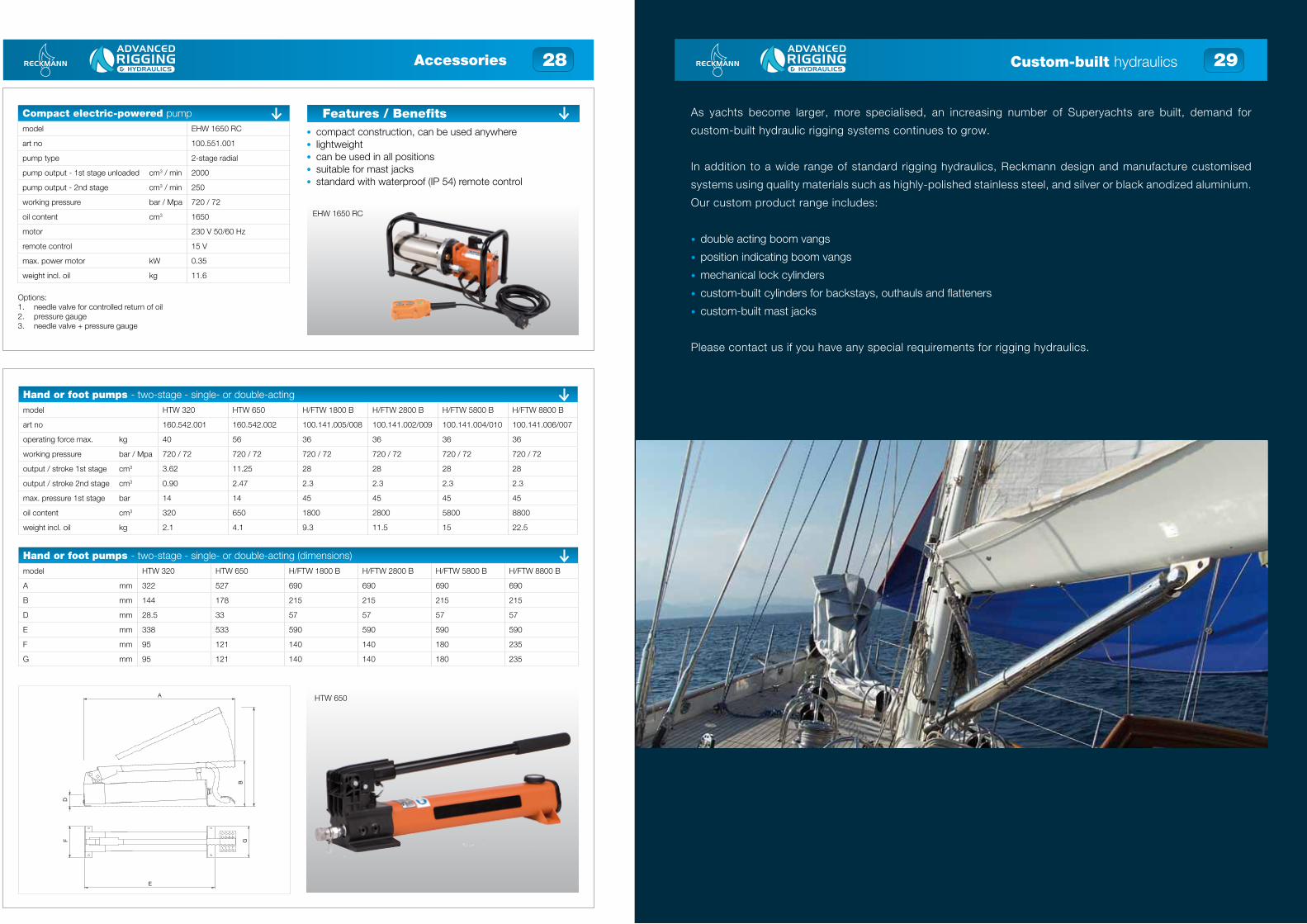
As yachts become larger, more specialised, an increasing number of Superyachts are built, demand for
custom-built hydraulic rigging systems continues to grow.
In addition to a wide range of standard rigging hydraulics, Reckmann design and manufacture customised
systems using quality materials such as highly-polished stainless steel, and silver or black anodized aluminium.
Our custom product range includes:
• double acting boom vangs
• position indicating boom vangs
• mechanical lock cylinders
• custom-built cylinders for backstays, outhauls and flatteners
• custom-built mast jacks
Please contact us if you have any special requirements for rigging hydraulics.
Custom-built hydraulics
Hand or foot pumps - two-stage - single- or double-actingmodel HTW 320 HTW 650 H/FTW 1800 B H/FTW 2800 B H/FTW 5800 B H/FTW 8800 B
art no 160.542.001 160.542.002 100.141.005/008 100.141.002/009 100.141.004/010 100.141.006/007
operating force max. kg 40 56 36 36 36 36
working pressure bar / Mpa 720 / 72 720 / 72 720 / 72 720 / 72 720 / 72 720 / 72
output / stroke 1st stage cm3 3.62 11.25 28 28 28 28
output / stroke 2nd stage cm3 0.90 2.47 2.3 2.3 2.3 2.3
max. pressure 1st stage bar 14 14 45 45 45 45
oil content cm3 320 650 1800 2800 5800 8800
weight incl. oil kg 2.1 4.1 9.3 11.5 15 22.5
Hand or foot pumps - two-stage - single- or double-acting (dimensions)model HTW 320 HTW 650 H/FTW 1800 B H/FTW 2800 B H/FTW 5800 B H/FTW 8800 B
A mm 322 527 690 690 690 690
B mm 144 178 215 215 215 215
D mm 28.5 33 57 57 57 57
E mm 338 533 590 590 590 590
F mm 95 121 140 140 180 235
G mm 95 121 140 140 180 235
Compact electric-powered pumpmodel EHW 1650 RC
art no 100.551.001
pump type 2-stage radial
pump output - 1st stage unloaded cm3 / min 2000
pump output - 2nd stage cm3 / min 250
working pressure bar / Mpa 720 / 72
oil content cm3 1650
motor 230 V 50/60 Hz
remote control 15 V
max. power motor kW 0.35
weight incl. oil kg 11.6
Options:1. needle valve for controlled return of oil2. pressure gauge3. needle valve + pressure gauge
EHW 1650 RC
• compact construction, can be used anywhere • lightweight • can be used in all positions • suitable for mast jacks • standard with waterproof (IP 54) remote control
Features / Benefits
HTW 650
Accessories
A
B
DF G
E

30 31
These hydraulic cutters are equipped with blades designed for wire rigging up to 16 mm. They are lightweight
but powerful, and extremely easy to operate. The integrated hand pump ensures a very compact design.
The cutters are supplied in a waterproof dry-bag, protected and ready for action.
Cutting a rig can be hazardous, but is sometimes essential to prevent further damage or loss of life. For
emergency situations like this, Reckmann has developed a special range of remote-operated cutters.
Equipped with blades designed for Rod rigging up to -115 (22.2 mm), the cutters lock onto the rig and remain
in place unattended. A hydraulic hand pump connected by a three metre hose allows the operator to stand
back from any flying ends if the rig is cut under tension.
Supplied in a waterproof protective case with wheels and retractable handle for easy transportation.
Emergency rig cutters Emergency rig cutters
Hand-operated wire & rod cuttersmodel EWC14H EWC16H ERC-12H ERC-30H
typ wire wire rod rod
capacity - - -12 -30
max. cutting size wire mm 16 20 7.1 11.1
max. cutting size dyform mm 14 16 - -
pump Integrated Integrated Integrated Integrated
storage dry-bag dry-bag dry-bag dry-bag
Remote-operated rod cuttersmodel ERC-30R ERC-60R ERC-115R
capacity -30 -60 -115
max. cutting size: wire mm 11.1 16.8 22.2
hose length m 0.437 0.660 0.875
pump remote remote remote
storage case (lxwxh) mm 560x466x265 560x466x265 560x466x265
Dry-bagEWC16H
ERC-30H
ERC-115R
ERC-30R

32 33System components
Plumbing Parts
We have a wide range of plumbing parts to install your hydraulic equipment perfectly on your yacht. These fit the
most current thread sizes.
Sustainable green oil
The Reckmann Eco Power hydraulic oil is a high quality detergent oil and has been specially compounded and
approved for use in all Reckmann Rigging Hydraulic units. This oil is available in different viscosities in one and five
litre containers and is used in all of our products.
System components
Plumbing - high pressure (440 bar)description art no
hydraulic high pressure hose (per meter) 632.011.115
SS hydraulic crimping coupler 7/16”JIC 160.583.030
hose pressing per coupler 999.000.130
through deck gland 5/32” (standard) 160.583.002
through deck gland 3/16” 160.182.005
SS elbow connection 7/16”JIC-1/8”NPT 160.583.025
SS adjustable elbow connection 7/16”JIC 160.182.003
SS T-connection 7/16”JIC-7/16”JIC 160.583.027
SS swivel T-connection 7/16”JIC-7/16”JIC 160.583.028
SS swivel side T-connection 7/16”JIC - 7/16”JIC 160.000.979
SS straight connection 1/4”BSP-7/16”JIC 160.583.019
SS straight connection 7/16”JIC-7/16”JIC 160.182.004
SS multiseal, 1/4” BSP 160.583.008
SS quick coupler 1/4” BSP (l) male 160.000.736
SS quick coupler 1/4” BSP (l) female 160.000.737
Plumbing - low pressuredescription art no
hydraulic low pressure hose (per meter) 160.570.031
LP elbow connection, 12 mm 160.00.688
LP threaded elbow connection, 12 x 12 mm 160.000.666
LP T-connection, 12 mm x 1/4” BSP 160.000.667
LP threaded T-connection, 12 x 12 x 12 mm 160.000.747
LP straight connection, 12 x 12 mm x 1/4” BSP 160.000.689
LP threaded straight connection, 12 x 12 mm 160.000.669
LP blanking plug 160.000.670
LP elbow 45°, 12 mm x 1/4” BSP 160.000.745
LP quick coupler, female, 1/4” BSP 160.000.742
LP quick coupler, male, 1/4” BSP 160.000.743
Oildescription art no
mineral hydraulic oil, biodegredable, ISO VG 15, 1 ltr. 100.581.051
mineral hydraulic oil, biodegredable, ISO VG 15, 5 ltr. 100.581.055

34 35System components
Hoses - 440 barmodel MH0.25 MH0.5 MH1 MH1.4 MH1.7 MH2 MH2.5 MH3
art no 160.570.056 160.570.042 160.570.009 160.570.047 160.570.043 160.571.010 160.571.040 160.570.029
length m 0.25 0.5 1 1.4 1.7 2 2.5 3
model MH3.4 MH4 MH4.5 MH5 MH6 MH7 MH7.5 MH8
art no 160.570.044 160.570.039 160.570. 160.571.011 160.570.053 160.570.045 160.570.036 160.570.052
length m 3.4 4 4.5 5 6 7 7.5 8
model MH10 MH12.5 MH13 MH14 MH15 MH16.5 MH18
art no 160.571.012 160.570.007 160.570.025 150.570.047 160.571.013 160.570.051 160.570.058
length m 10 12.5 13 14 15 16.5 18
Hoses with through deck gland - 440 barmodel MH1D MH1.2D MH2D MH2.5D MH3D MH3.5D MH4D MH5D MH5.5D
art no 160.570.033 160.570.004 160.571.001 160.570.010 160.570.037 160.570.005 160.570.057 160.571.002 160.570.026
length m 1 1.2 2 2.5 3 3.5 4 5 5.5
model MH6D MH7.5D MH8D MH8.5D MH9D MH10D MH10.5D MH12D MH12.5D
art no 160.570.014 160.570.049 160.570.015 160.570.023 160.570.016 160.571.003 160.570.034 160.570.022 160.570.035
length m 6 7.5 8 8.5 9 10 10.5 12 12.5
model MH13D MH14D MH15D MH16D MH17.5D MH20D MH24D
art no 160.570.021 160.570.041 160.570.017 160.570.028 160.570.038 160.570.032 160.570.055
length m 13 14 15 16 17.5 20 24
Notes

36Notes

© Reckmann 2013 980.000.383
DisclaimerWhile the greatest care has been devoted to the content, it is possible that the information in this printed matter is incorrect or incoplete Reckmann Yacht Equipment GmbH and its affiliated companies (hereafter: Reckmann) cannot be held liable in any way for the consequences of activities undertaken based on this printed matter. If you have any doubts about the correctness or completeness of the information, you shall contact Reckmann. Nothing from this printed matter can be copied and/or made public in any way without the explicit authorisation of Reckmann.
NO COMPROMISE
© Reckmann 2013 980.000.383
DisclaimerWhile the greatest care has been devoted to the content, it is possible that the information in this printed matter is incorrect or incoplete Reckmann Yacht Equipment GmbH and its affiliated companies (hereafter: Reckmann) cannot be held liable in any way for the consequences of activities undertaken based on this printed matter. If you have any doubts about the correctness or completeness of the information, you shall contact Reckmann. Nothing from this printed matter can be copied and/or made public in any way without the explicit authorisation of Reckmann.
+44 (0)2380 454 [email protected]
Manufacture • Installation • RepairW o r l d W i d e S e r v i c e
UK Distributors for Reckmann Yacht Equipment GmbH
Advanced Rigging & Hydraulics, a division of Hamble Yacht Services Refit and Repair Ltd, HYS Port Hamble, Hamble, Hampshire, SO31 4NN. Co no: 686473. VAT No. 206 0828 33