Embed Size (px)
Citation preview

RIGGING MANUAL

Safety Afloat
This instruction manual is not a guide to sailing your craft and it should not be considered suitable for the task of learning to sail a boat. Please read the manual before rigging and sailing your Laser 2000.
Before you go sailing:
o Check you are wearing suitable clothing and safety equipment for the conditions and time of year.
o Always wear a buoyancy aid or life jacket o Make sure a third party knows where you are sailing and
how many there are of you. o Check the weather forecast o Check the time of high and low tides if applicable. o Seek advice of local conditions if sailing in a new area. o Always check the condition of your craft before setting off. o A sailor’s safety knife should be carried on board. o Check for overhead cables when rigging, launching
and recovering.
On the water:
o Conform to the sailing rules of the road. o Look out for changing weather conditions. o Never sail beyond your ability or that of your crew. Ensure
that you and your crew can cope with any changes in the wind conditions
o Understand and be competent in the sailing skills and righting techniques.
2

Important information There are three hatches and one transom drain bung on the Laser 2000, these must all be checked to ensure they are fitted correctly and done up tight prior to every time you sail:
Hatches 1 & 2 are found at the aft edge of the foredeck.
(Fitted to facilitate additional on the water storage only)
Hatch 3 can be found on the inboard surface of the stern deck.
The transom drain bung can be found below the lower rudder
gudgeon.
Example of INCORRECT hatch
fitment:
NB: Correct fitment of the transom drain bung and hatch 3, is fundamental to on the water safety and performance of the Laser 2000.
3

Laser 2000 Rigging Instructions The Laser 2000 rigging instructions are a guide to rigging your boat. Due to production supplies certain parts may be different from those shown in description, colour, and specification. Performance Sailcraft Europe reserves the right to change specifications without prior notification. LASER CENTRE Options, accessories and spares are available from Laser Direct +44 (0) 1327 841610
www.lasersailing.com
The Laser Centre Station Works Long Buckby Northampton NN6 7PF UK
Contents Page
1. Glossary 5 2. Useful boat terminology 6 3. Maintenance and service 7-8 4. Cordage Lengths 8 5. Sail number positioning 9 6. Rigging and raising the mast 10-13 7. Rigging The Trapeze 13-14 8. Boom & Vang 15 9. Sails: 16-23
a. Jib 16-17 b. Gennaker 18-20 c. Mainsail 20-21 d. Outhaul 21 e. Cunningham 22 f. Reefing The Mainsail 22-23
10. Rudder 23 11. Launching & basic safety on the water 24-25 12. Laser 2000 Capsize Technique 26 Customer Help Line: Please contact Customer Services on Tel: 00 44 (0) 1327 841608.
4

Glossary Bow: Front of the boat Stern: Back of the boat Fore: Forward Aft: Rearward Clew: Back lower corner of a sail Tack: Forward lower corner of sail Head: Top corner of sail Luff: Forward edge of the sail Foot: Bottom edge of the sail Leech: Rear edge of the sail Burgee: Wind direction indicator (usually a small flag) Batten: A thin stiffening strip in the sail to support the leech Mast: Main vertical spar supporting the rig/sails Boom: Spar at the Bottom of the mainsail Gennaker pole: the Pole, which extends to fly the gennaker tack from. Cleat: A fitting used for holding /securing ropes Forestay: The wire supporting the mast at the bow of the boat Shrouds: Wires that hold mast in boat and supporting the mast from ¾ up and out to hull side. Attached with shroud adjuster to shroud anchor point Lower shrouds: Wires that tie off ¼ up mast and shackle to shroud anchor points Jib: Front sail Sheet: Rope for controlling the inward/outward position of the sail Gennaker: Isometric sail hoisted when sailing downwind Gunwale: The outermost edge of the boat Gudgeon: Fitting on the transom and rudder used to hang rudder Cunningham: Purchase system for tightening the forward edge/luff of the sail Gnav: Purchase system for tightening the rear edge/leach of the sail Vang: Otherwise known as the Kicking strap or Gnav Outhaul: Purchase system for tightening the bottom edge/foot of the sail Halyard: A rope or wire used to lower or hoist sails Mast Heel: Fitting on the bottom edge/foot of the mast Mast step: Fitting on the boat where the mast heel/foot of the mast is located Spreaders: Metal struts placed in pairs to support the mast side ways and control the bend in the mast Stem fitting: Stainless fitting at the bow which the forestay attaches Rudder: Blade and attachments used for steering the boat
5

Useful Boat Terminology
er Hull
Luff
Jib
Shroud
Mainsail
Mast
Clew
Tack
Gennaker
Gennaker Pole
Foot
Rudd
Leech
Batten
Centreboard
6

Maintenance and Service
• Keep the equipment clean by frequently flushing with fresh water. In
Excess water should be removed from the hull.
Ropes, rigging and fittings should be checked at regular intervals for wear
All moving parts should be lightly lubricated to avoid jamming, i.e.,
Inspect shackles, pins and fittings – tape up to stop snagging and coming
When refastening screws do not re – use Nylock nuts more than three
Damaged or worn parts should be replaced.
• Sails should be thoroughly washed down with fresh water, dried and
Trailers and trolleys should be rinsed with fresh water and checked at
• It is recommended that the trailer/road base be serviced annually.
• The trailer/road base should never be immersed in water.
• Trailers and Trolleys supplied by Laser are designed to transport the hull in
n
• Only people with relevant equipment and skills should undertake repairs to
Under covers for Laser products should be produced from breathable or
.
d es
foam or wood.
corrosive atmospheres stainless parts may show discoloration/brown staining around screw holes and rivets, this is not serious and can be removed with a fine abrasive.
• •
and tear.
• McLube, Dry Teflon or a dry silicone based spray. Do not use Oil.
• undone.
• times and be careful not to over-tighten, as there is a risk of stripping the thread.
•
stored in a dry place.
• regular intervals.
the best possible manner to avoid damaging the hull. For instance Laser does not recommend supporting hulls on rollers except on the keel line. We also recommend gunwale-hung trolleys for our smaller products. Hullssupported by a trolley bunk or wide strap must have the ability to drain the water away from the hull. Trolley bunks padded with carpet or foamcan cause blistering and changes to the hull colour. Please do not transport your Laser product on a trailer or trolley that has not beespecifically designed for the product. Hulls damaged through using anincorrectly designed or wrongly set up trailer or trolley are not covered under warranty.
the glass fibre hull. Contact Laser Centre for advice.
• semi breathable fabric to allow moisture to evaporate away from the hullThis is essential to prevent damage to gel coat. However, the hull should never be left in the undercover wet or damp. A combination of moisture and heat over an extended period can also damage the gel coat. The under cover is designed to protect the hull when being transported anshould be removed when the hull is being stored. Typical damage includsmall bubbles or blisters, excessive print through of glass reinforcement,
7

UV light will cause fading to some components and fittings, a cover is recommended to reduce the UV degradation.
• n
climbing on to the centreboard and back in to the boat after capsize. (As
• screws
on the plastic friction device on the leading edge of the centreboard within f
Cordag
•
WARNING: When wearing a trapeze harness, take particular care whe
the trapeze harness hook could easily damage the hull or deck)
If your centreboard will not stay down during sailing, tighten the
the centreboard case. (As the presence of water changes the coefficient ofriction within the case, this device is best “tuned” using a long shaft posi-drive screwdriver whilst on the water on a relatively calm day)
e
b sheet
MainsheeJiGennakeMainsheCunningCunningKicker/VKicker/VToe-straLashing Rear ToeMain ToeRightingRightingCentrebo
Centreboard Friction Devic
e lengths
1 x 6.0 metres, 8mm, 8 plait, matt, white 1 x 6.6 metres, 8mm, 8 plait, matt, white
he Brid e
1 2
hite ck cord
-strap Shock cord
e e
t
r s et 1 x 9.0 metres, 6mm, 8 plait matt, blue et l 1 x 2.2 metres, 4mm, Excel Racing, purpleham Part 1 x 5.0 metres, 4mm, 8 plait p/s, lime ham Part 1 x 0.8 metres, 4mm, 8 plait p/s, lime ang Part 1 1 x 5.5 metres, 4mm, 8 plait p/s, red ang Part 2 1 x 2.5 metres, 5mm, Excel Racing, redp Lashing 4 x 0.6 metres, 6mm, 8 plait p/s, black
3 x 0.2 metres, 1 x 0.8 metres, 8 plait, w-strap Sho - 1 x 0.3 metres, 5mm, Shock cord, blue
- 1 x 2.0 metres, 5mm, Shock cord, blue Line 2 x 1.5 metres, 4mm, 8 plait p/s, red Line Shock-cord 2 x 0.9 metres, 5mm, Shock cord, blue ard Lin 1 x 0.75metres, 8mm, 8 plait p/s, whit
8

ail Number PositioningS
bers in a dry, clean and wind free environment.
2. Numbers on the starboard side of a sail are always higher than those on
5. number in the sequence should be positioned on the parallel line ech.
7. below the third
Starboard (Right Han
It is advised to apply the sail num
1. Lay the sail on a flat surface starboard side up.
the port. 3. Mark a parallel line 76mm above the third batten down from the head of
the sail. 4. Mark a point on the line 76mm in from the leech.
The first you have drawn commencing 76mm in from the le
6. Subsequent numbers should be spaced 60mm apart. Turn the sail over and position the port numbers 76mm batten down from the head.
8. Work backwards, commencing 76mm in from the leech.
m
60mm
76mm76mm
76m
d) side of Mainsail
9

Rigging And Raising The Mast
2. Ensure the halyards, shrouds and lowers shrouds are led to the gooseneck/base of the mast and
res in the the
4. Fit the spreaders.
ee page overleaf for fitment diag
ip: Best practice is to fit the evis pins from above to ensure all
5. Ensure that all the spreader pins and rings are taped up or serious damage could occur to the sails.
1. Unwrap the mast.
each halyard rope end has a knot tied in it.
3. If applicable, fittop “T” terminal
t e wi positions onrapez
mast. (Please note: The Laser 2000 Trapeze kit is optional and is not supplied as standard)
(Sram.)
(Tclsplit rings are positioned on theunderside of the spreader bracket/bars.)
10

Laser 2000 Spreader Instructions
Primary Pin: Fit down througAdjuster Pin: Fit down through
Spreader End CaThe spreader end casizes are identified on the front face of the end cap (See diagramrequire for your mast, please see the table below. The end cap can also be rotated so that the shroudthe spreader end (see diagram above). To find out which positiotable below. To attach theEnsure that the shroud is tensioned between T-Terminal and spfirmly. This meLength Adjustment: Described by the numvisible). Please see the table below for your class specific p SAll clevis pins and the outboard end of the spreader extrusion. This will reducesails/halyards becoming damaged. Self-amalgamating tape is best, but
Primary Adjuster End cap pLaser 2000 Aft 1A Aft
Attachment of Spreader.
h the bracket’s primary ho
hole 3 on the bracket an
le and thro
d
p: p incorporates two shroud wire slots to give
can be posi
shroud, slacken the end screw, rotate the end clam
thod “locks in” the dihedral angle.
ber of adjustment holes visible, (e.g. In the
ecurity must be fitted with the flat head on top, and locke
PVC electrical tape is an ad
Class Bracket Connection Pin
ugh the Fwd spreader hole.
B on the spreader bar.
Spreader Ends
BC
DA
E FwAPrimar
12
34
567
y ft
3.0
Rotate as Forward position
necessary
5
abov
n is re
reade
ositio
chafe
os’n
a tigh
tioned
p if n
diag
d with
equat
(See Table) .n
Aft positioe). To find which wire slot you
quired for your mast, please see the
r tip, and then tighten the screw
ns.
on the mainsail and prevent flailing
Visible Holes Wire Dia. 3.0mm 0
t grip on either 2.5 or 3mm wire. The
at either the forward or aft position of
ecessary, then insert the shroud.
ram above there are 1 ½ holes
a split ring. Tape all split rings, pins
e alternative.
Outer End
2
11

12
6. Raise the mast and position the
mast heel in the centre of the mast step. (Note - This is a two person operation as someone will need to hold the mast upright while the shrouds and forestay are connected)
CAUTION
CON TACT WITH OVERHEAD ELECTRICAL WIRES COULD BE FATAL, EXERCISEXTREME CAUTION WHEN RAISING THE MAST LAUNCHING & SE AILING.
tgaged correctly
as show
ud anchoron in the
e vernier
9. Attach the on the port
7. Ensureposition
he mast heel is ed and enn.
8. Attach the shrouds to the shro
point with the adjuster pin positi3rd hole down on the back of thadjuster.
forestay on to the deck fairlead bow deck as shown.
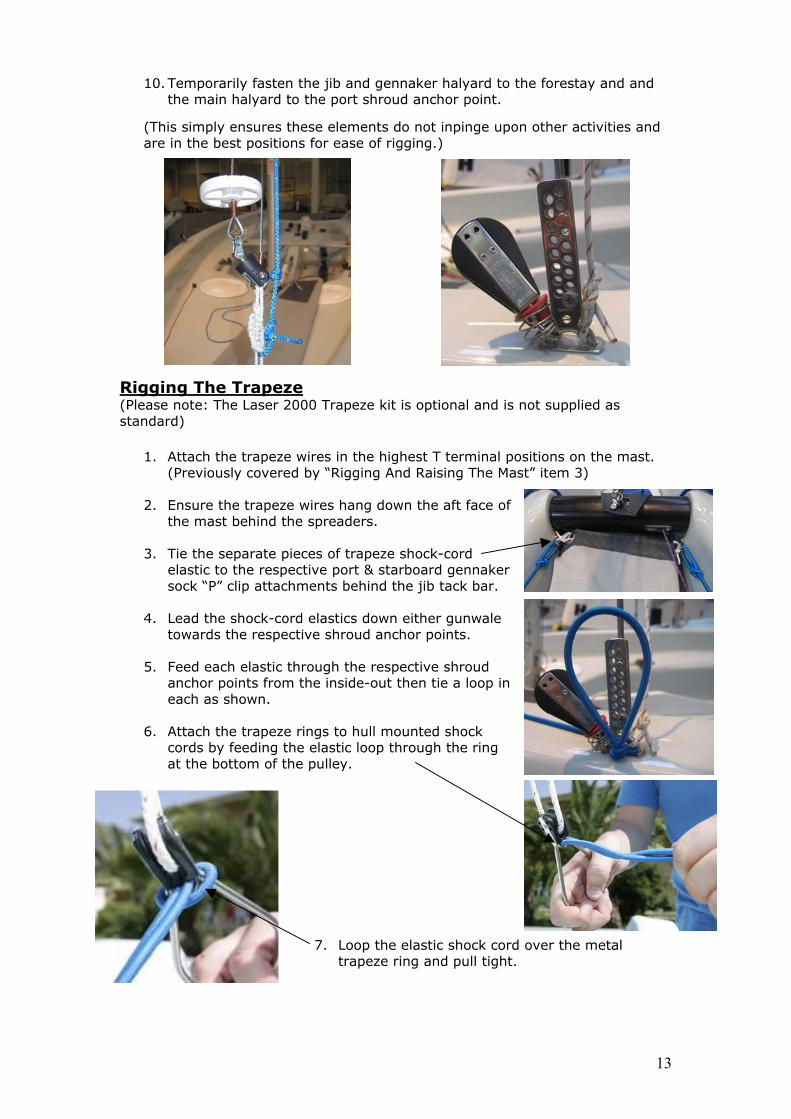
10. Temporarily fasten the jib and gennaker halyard to the forestay and and the main halyard to the port shroud anchor point.
(This simply ensures these elements do not inpinge upon other activities and are in the best positions for ease of rigging.)
igg
13
cord over the metal
R ing The Trape
e note: The Laser 2000 Trapard)
Attach the trapeze wires in the high(Previously covered by “Riggi
Ensure the trapeze wires hang
ze (Pleas eze kit is optand
1. est T st. ng And Raisin
2. down the
the mast behind the spreaders.
tic to the respective port & starboard gennaker sock “P” clip attachments behind the jib tack bar.
4.
towards the respective shroud anchor points.
5. pective shroud anchor points from the inside-out then tie a loop in
6.
cords by feeding the elastic loop through the
7. Loop the elastic shock trapeze ring and pull tight.
tional and is not supplied as
terminal positions on the mag The Mast” item 3)
aft face of
s
3. Tie the separate pieces of trapeze shock-cord
elas
Lead the shock-cord elastics down either gunwale
Feed each elastic through the res
each as shown.
Attach the trapeze rings to hull mounted shock ring
at the bottom of the pulley.

8. Tip - Best practise is to tie two double half hitch
line.
9. Attach the lower shrouds to central hole of tadjusters with the forward lower shrouds are part kit and are
10. To avoid ob
m
nd oface of the
tunedoff until the jib is hoised and rig tenapplied, at which point they should be adjusted until both wires are equal, JUST in
.
e
shroud anc
uds are supplied to support the mast and s ap
THE TRAPEZE SHOULD NEVER BE USED WITHOUT PRIOR
stopper knots a hand width apart in the adjuster
the lowest he shroud vernier
shackle facing as shown. (Please note: The
of the trapeze not supplied as standard)
struction, ensure the
11. Loosely attach the other eto the eye on the front above the gooseneck.
12. The lower shrouds cannot be
shackle pins are fitted from the inside-out, the more favourable longer tersolution would be to discard the shackle pins in favour of the pan headmachine screws also supplied.
f the lowers mast just
and tied sion is
tension but not pulling the mast aft and tied
13. Grip tapthe gunwa
should be applied parallel to le edge commencing
approximately 200mm in front of the hor points extending aft.
PLEASE NOTE: The lower shroprotect it from the load
FITMENT OF T
plied through use of the trapeze –
OWER SHROUDS.
HE L
14

Boom and Vang 1.
2
3. Ensure theshackled securely
ast.
r purchas ring t system.
Aft Block
own.
sht s
ainsheet
t in the c tion bossed on the side of
ts art.
ip - Best practise is to tie tf the mainsheet to onraps to prevent tangling and the lling overboard.
15
Unpack the boom.
. Attach the boom to the mast as shown.
lower vang purchase system is to the tang on the lower aft
face of the m
se assembly here are no
4. Hook the vang uppeon to the boom en
sts or fouls in the
utwi
5. Tie the mainsheemainsheet bridle ua sh
t through the block on the sing a half hitch stopper knot
eet through the blocks and to wivel cleat as shown.
Tip - double check the mthrough the auto ratcheshown by the arrow emthe auto ratchet block.
6. Feed the main
the mainshee
passes orrect direc
7. Vang tension is controlledaft rope and fairlead/cleahw
using the on top of the
he loose end e of the rear toe
sheet
t Tostfa
Sails
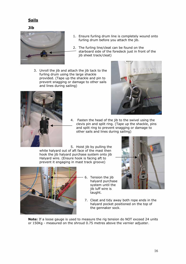
1. Ensure furling drum line is completely wound onto
furling drum before you attach the jib.
2. The furling line/cleat can be found on the starboard side of the foredeck just in front of the jib sheet track/cleat)
h the jib tack to the g th
sgging or dam
sailing)
4. Fasten the head of clevis pin and split riand split ring to prevother sails and lin
t of aftu
nsure hgaging in mast track groove)
se
il the is
taught.
7. Cleat and tidy awayosi
.
meas g tension do NOT exceed 24 units 75 metres above the vernier adjuster.
Jib
3. Unroll the jib and
furling drum usinprovided. (Tape up theprevent snaand lines during
attace large shackle
hackle and pin to age to other sails
the jib to the swivel using the ng. (Tape up the shackle, pins
t snagging or damage to es during sailing)
en
5. Hoist jib by pulling the
face of the mast then rchase system onto jib ook is facing aft to
white halyard ouhook the jib halyard pHalyard wire. (Eprevent it en
6. Tension the jib
halyard purchasystem untjib luff wire
both rope ends in the tioned on the top of
halyard pocket pthe gennaker sock
ure the riNote: If a loose gauge is used to or 150Kg - measured on the shroud 0.
16

17
then pull the two trailing ends of the sheet through the loop you have created to lock them in place as
ng them through their respective
starboard jib fairleads/cleats.
10. tie the sangling and i
11. g line. The the
in front of the jib sheet track/cleat)
8. Find the centre of the jib sheet and pass it through the clew of the jib,
shown.
9. Pass one jib sheet either side
of the mast before threadi
heet ends together in the middle of the nhibit sheets falling overboard.
port and
Tip – Best practise is toboat to prevent t
Furl the jib by pulling the furlinfurling line/cleat can be found onstarboard side of the foredeck just
a. b.

12. If the trapeze option is fitted: Now the rig tension has been applied, the lower shrouds can be tuned, they should be adjusted until both wires are equal, JUST in tension, but not pulling the mast aft, then tied off.
Genn
aker
1. Ensure the end of the gennaker halyard taken from the base of the mast is free of knots and tangles.
2. Take the gennaker halyard from the base of the
he attached to the n in the picture)
4. Pass the halyard across the boat and through the pulley block at the aft end of the gennaker sock.
5.
er extension and carefully pass the end of the halyard up the sock until you can grasp it from the front end of the gennaker sock opening.
mast and pass forward, under the gennaker sock and round the gennaker pole outhaul block. (Tgennaker pole outhaul block isrope led from the pole as show
a/
3. Thread the halyargennaker edge of the
d aft halyard cleat
foredeck on
nd through the fairlead at the aft the starboard side.
Tie the end of the halyard to something such as a batten or till
18

6. This is known as the downhaul end of the gennaker halyard and should be temporally tied around the jib tack bar while the batten/extension is removed from the gennaker sock.
7. Note: The up-haul end of the gennaker halyard is ious
idel) and
patch usinline comes out of the frpole.)
d patch, (written on the naker halyard (up-haul)
se of the forestay and tie it to tch using a bowline.
nnaker halyard (down-haul)
11. Identify the clew patch, the sail)
attach the centre of the ennaker sheet to the clew of the gennaker. (A per jib sheet to jib clew previously covered in section Sails - Jib)
8. Unfold the gennaker,(written on the sailine to the tack
tied at the base of the forestay from a prevrigging exercise.
ntify the tack patch securely fasten the tack
g a bow-line. (The tack ont of the gennaker
ch
Note: Please check there is also a double half hitpper knot in the tack-line and gennaker halyard roximately 100mm prior to the bowline you have .
stoapptied
9. Identify the hea
sail) untie the genfrom the bathe head pa
10. Untie the ge
from the jib tack bar:
a.Pass through the lring on the port side of
ower downhaul patch th
.Secure to the upper ownhaul patch using a owline.
e sail.
bdb
(written on gs
19

20
ets
gh the gennaker sheet ratchet blocks attached to the shroud anchor points. There are arrows on the ratchet
t
t pass f
14.
wind and hoist the gennaker. Take great t
d around the trolley; a second person should help with this to ensure it
15 UP
T BECO
16. pull the gennthe halyard through the block at the aft end of the sock. A second person
th
Ma
(Note – The sheets mus
13. Tie the free ends of the together.
12. Pass the free ends of the gennaker sheaft (One sheet either side of the jib luff) and throu
block to indicate which way the rope should pass. When under load, the ratchewill engage.
orward of the shrouds at all times.
gennaker sheet
THE GENNAKER SLOWLY MES TANGLED OR TIGHT.
aker into the sock by pulling
Ensure the boat is pointing directly into the
care to ensure that the gennaker does noget snagge
does not snag anywhere. Check the gennaker is not twisted and the Sheets arenot tangled with the halyard.
. ALWAYS TAKE GREAT CARE TO PULLAND DO NOT KEEP PULLING IF I
Un-cleat the halyard and gently
should help with this and be positioned at the front of the boat to ensure e gennaker does not get snagged anywhere.
insail
Remove the mainsail from its the bag and unroll.
1.
2. Ensure all battens are tight in their pockets and the Velcro locking mechanisms are positively engaged.
it is head to wind (bow
facing directly in to the wind).
4. e hull with the luff closest the bow (front) and the
5. Take the main halyard:
spreaders.
the head of the sail using a bowline.
to
3. Position the boat so
Place the mainsail in the cockpit of th
leach closest the stern (back).
a. Ensure there are no twists in the halyard and it is clear of the
b. Tie the halyard to
c. Locate the head of the mainsail inthe mast track.

6. Hoist the mainsail using the main halyard block/cleat assembly on the lower port side of the mast.
7.
ce will be required to feed the mainsail in to the
isted, cleat
the halyard pocket positioned on the
Outha
Note: Hoisting the mainsail is a two person operation as assistan
mast track while the other hoists using the halyard (This will prevent the sail pulling out of the track and jamming which could cause luff rope damage.)
8. When the mainsail is fullyand tidy away the halyard rope end in
ho
top of the gennaker sock.
ul
1. cltop of the boom.
rough t/left
to starboard/right side) and anc ored on ot d
3.
rd end of the boom.
Feed the plastic slug slide on the ew outhaul into the cut out on the
2. The outhaul line is then passed ththe lowest eye in the sail (From por
hthe starboard/right side with a simple knlocated in the slot formed in the boom encasting.
Outhaul tension is controlled using the forward rope,the forwa
cleat and fairlead at
21

Cunningham
1. Pass the rope at the end of the Cunningham
purchase system through the eye at the
2. Anchor the end of the
lf to
t
. Cunningham tension is controlled using the rward rope and fairlead/cleat on top of the
bottom of the mainsail luff (from port/left hand to starboard/right hand side).
Cunningham purchase system by sliding a hahitch knot inmast track jusbelow the gooseneck.
Reefing The Mainsail
3focockpit centre console.
If it is windy and you feel you will be overpowered in the Laser 2000 it is wise to
ef the mainsail:
1. Remove the Cunningham from the tack eyelet.
he
re
2. Remove the outhaul from t
clew eyelet.
100mm
e boom track. d
3. Slide the clew outhaul slug slide out of th
4. Un-cleat the mainsail halyarand lower the mainsail until the upper reefing tack eyelet is around 100mm above the gooseneck and the foot of the mainsail is just beginning to touch the thwart/sub deck as shown.
22
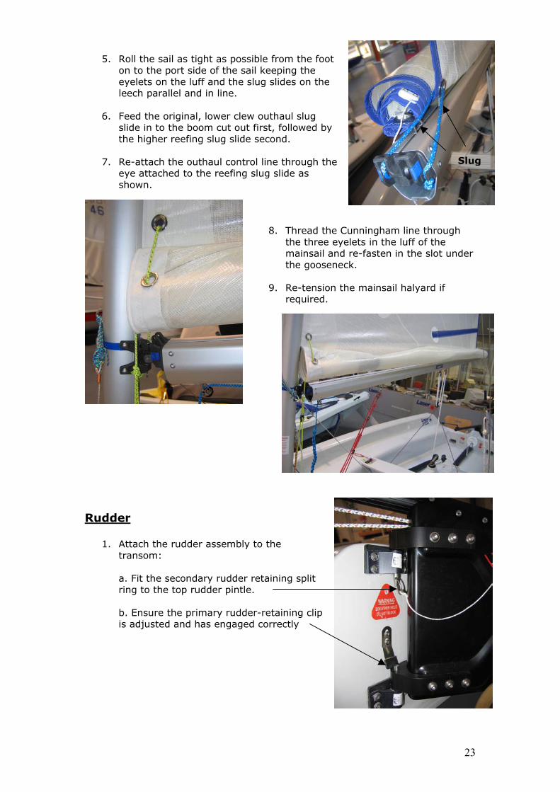
5. he foot on to the port side of the sail keeping the
6. w outhaul slug
slide in to the boom cut out first, followed by
7. ugh the
to the reefing slug slide as
8. Thread the Cunningham line througthe three eyelets in the luff of the
ainsail halyard if
udder
g
Roll the sail as tight as possible from t
eyelets on the luff and the slug slides on the leech parallel and in line.
Feed the original, lower cle
the higher reefing slug slide second.
Re-attach the outhaul control line throeye attachedshown.
mainsail and re-fasten in the slot uthe gooseneck.
Re-tension the m
9. required.
R
ch the rudder assembly to the transom:
condary rudder retaining split ring to the top rudder pintle.
retaining clip
is adjusted and has engaged correctly
1. Atta
a. Fit the se
b. Ensure the primary rudder-
Slu
h
r nde
23

Your Laser 2000 Is Now Ready For Launching.
Launching And Basic Safety On The Water
Before You Go Sailing:
o Check you are wearing suitable clothing and safety equipment for the conditions and time of year.
o s where you are sailing and how many
o igh and low tides if applicable. s if sailing in anew area.
ing off.
o Always wear a buoyancy aid or life jacket Make sure a third party knowthere are of you.
o Check the weather forecast Check the time of h
o Seek advise of local conditiono Always check the condition of your craft before sett
CAUTION
CONTACT WITH O E L, EXERCISE LECTRICAL WIRES COUVERHEADUTION WH
LD BE FATANCHINGEXTREME CA EN RAISING THE MAST, LAU & SAILING.
Launching
e the mainsail with the boat facing into the wind.
y.
wind.
.
o Rais
o Launch the boat using the appropriate launching trolle
o Take the boat into the water with the bow facing into the
o Ensure that there is enough water to float the boat off the trolley
24

o One person should hold the boat whilst the other gets in and prepares to set off.
o When udder fully.
o he rudder downhaul in the cleat on the tiller and ensure that the wing nut on the side of the rudderstock is tight.
The R ly Down Position At All
Times When Sailing And Isometric Boat Like The Laser 2000.
On Th
there is enough water below you, lower the centreboard and r
Cleat t
udder And Centreboard Should Be In The Ful
e Water
he sailing rules of the road.
o Look out for changing weather conditions. crew. ills and righting techniques.
o Conform to t
o Never sail beyond your ability or that of your o Understand and be competent in the sailing sk
Enjoy Your Laser 2000 Sailing!
25

26
Laser 2000 Capsize Technique When sailing your La it is highly probable that from ti othing to be nduly concerned about. In the event of a capsize we advise you follow the
rs of the crew a for and safe. deployed, drop the sail back in to the sock.
and ensure iately after
5. the bow during
.
6.
e
7.
ight position quickly. It should
8.
n
in to the
10.
drill
11.
ser 2000 in breezy or blustery conditions,me to time you will capsize. A capsize is n
uprocedure documented below:
Righting the Boat
1. Ensure all membe2. If the gennaker is
re accounted
3. Release the main/jib sheets and vang from respective cleats the sheets are fully extended to avoid the boat sailing immedrighting.
4. If the boat inverts, first recover the boat on to its side. In adverse conditions and with more than two crew it is recommended that the largest crew member swim to the bow and holdrighting and until all other crew members have re-boarded after righting(This ensures the boat swings in to the safe head in to wind position upon righting) It is recommended to use the “scoop” recovery system for crewmembers not involved in the righting procedure. When the boat is on its side, the crew members to be scooped should move to the inner lower side of the boat as close to the center of the boat as possible. As the boat is righted, these crew members will be “scooped” onboard the boat ready to help other re-board. “Scooping” should only be attempted with practice and should only be commenced after the boat is stabilized on its side by a crewmember who is securely located on the centerboard and holding thcapsize righting line under the gunwale. This is to prevent the boat frominverting and potentially trapping the crew. Righting is effected by a crewmember standing on the centerboard movingout towards the end of the board whilst leaning out holding on to the righting line. The boat will recover to the uprnormally only require one average size person to effect righting on the centerboard. Immediately after righting the tiller should be pushed fully towards the mainsail to stop the boat sailing until all crew have re-boarded.
9. Re-boarding can be undertaken over the windward side of the boat usingthe righting line as a step or over the transom. A grab rail is positioned othe inner face of the sub deck to assist with pulling yourself backboat. If the person in charge of the boat or the crew are inexperienced in capsizing and righting procedures it is advised to practice drills under skilled supervision and in any event, close to assistance prior to the being used in earnest. All crewmembers should wear an approved buoyancy aid at all times whilst on the water.


![Pre Rigging - boats-yachts.ro control si... · 01/2010 [B]3.a Pre Rigging Pre Rigging kit examples Pre Rigging kits: Twin digital gauge kit example 2x • Pre Rigging Dual Top Mount](https://img.dokumen.tips/doc/110x75/5b01b56a7f8b9a6a2e8ea25d/pre-rigging-boats-control-si012010-b3a-pre-rigging-pre-rigging-kit-examples.jpg)


![PDF[1.8MB] - Tokyo Chemical Industry Co., Ltd](https://img.dokumen.tips/doc/110x75/62073f2949d709492c2f747a/pdf18mb-tokyo-chemical-industry-co-ltd.jpg)