Embed Size (px)
Citation preview

Power Connection Box
Service Pipe
Control Panel
Power Transformer
Exterior surfaces of SKIN EFFECT CURRENT SYSTEMSare electrically grounded. The voltage is impressed betweenthe cable and the inner surface of the heat tube.
The Most ReliableCost-EffectiveHeat Tracing SystemFor Long Pipelines
A C Volts
A C Volts
RICWILSKINEFFECTCURRENTTRACEDSYSTEMS

HEAT
CURRENT
The power circuit for a basic, single-phase loadSKIN EFFECT CURRENT TRACING SYSTEMconsists of a transformer for isolation and specificvoltage, primary and secondary current protection, an operating contactor and a temperaturecontrol device. Additional tubes on a single pipe, if required, are usually fed from multi-phasetransformers to provide balance on a three-phase source. All thermal and electrical characteristicsare designed to ensure optimal performance based upon your requirements.
Typical Insulation Over The Entire System
CircuitBreaker
Contactor
Sensor
TemperatureControl
Transformer
ToSupply
Pull Box
Temperature Sensor
Electric Cable
Heat Tube
Electric SKIN EFFECT CURRENT TRACING combines the engineeringprinciples of skin effect and proximity effect. Skin effect is analternating current phenomena whereby AC current flows inthe outer surface of a carbon steel conductor. Proximityeffect is an electromagnetic force whereby equalcurrents in opposite directions attract. By placingthe electric cable inside the heat tube, thecurrent is drawn to a thin section of theheat tube inner wall. Heat generatedfrom the current is dispatchedthrough the heat tube walland into the service pipeby conduction.
Custom Designed and Supplied in accordance with ANSI/IEEE 844,NEC 426, 427 and your specific application requirements.Factory Fabricated Tracing System packaged with prefabricatedpreinsulated piping ensures the physical, thermal and electricalintegrity of the system.Factory Mutual Approved forhazardous environments.Only One Power Feed PointRequired for pipelines up to 16 miles.High Power Factor contributes tohigh operating efficiency.Proprietary Computer EngineeringSoftware provides heat up dynamics and other pertinentengineering data, relating to your application.Groundable – No exposed surfaces carry electricpotential. The entire pipeline and heatingsystem can be grounded.Easy To Repair/Minimum MaintenanceRequired – Pull box affords easyaccess to the electric cable forinspection or replacementwithout disturbing theinsulation, protectivejacketing or heattube.
Terminating Box
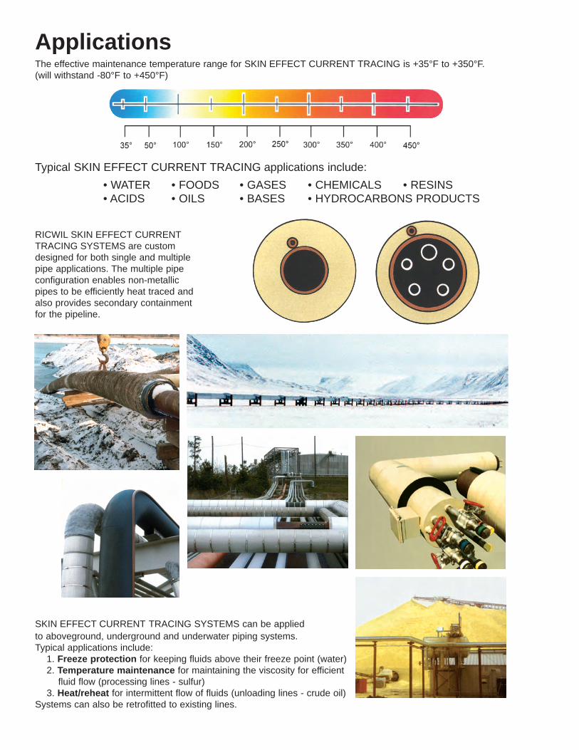
ApplicationsThe effective maintenance temperature range for SKIN EFFECT CURRENT TRACING is +35°F to +350°F.(will withstand -80°F to +450°F)
SKIN EFFECT CURRENT TRACING SYSTEMS can be appliedto aboveground, underground and underwater piping systems.Typical applications include:1. Freeze protection for keeping fluids above their freeze point (water)2. Temperature maintenance for maintaining the viscosity for efficientfluid flow (processing lines - sulfur)
3. Heat/reheat for intermittent flow of fluids (unloading lines - crude oil)Systems can also be retrofitted to existing lines.
RICWIL SKIN EFFECT CURRENTTRACING SYSTEMS are customdesigned for both single and multiplepipe applications. The multiple pipeconfiguration enables non-metallicpipes to be efficiently heat traced andalso provides secondary containmentfor the pipeline.
Typical SKIN EFFECT CURRENT TRACING applications include:• WATER • FOODS • GASES • CHEMICALS • RESINS• ACIDS • OILS • BASES • HYDROCARBONS PRODUCTS

Heat Tracing is the use of an externally applied heatsource on a pipeline to compensate for heat lossesthrough the thermal insulation.
Heat tracing evolved from the need to maintainthe flow of low, medium and high temperatureliquids through a pipeline, regardless of thesurrounding environment.
The primary applications for heat tracing are:1) freeze protection, 2) temperature maintenanceand 3) heat/reheat.
Early heat tracing methods, utilizing steam orhot fluids, were inefficient in their use of thermalenergy and their ability to maintain a uniformtemperature along the pipeline. Frequentinspection and care was required for thesesystems.
Electric heat tracing has significant advantagesover other methods:
Reliable, Uniform, Controllable HeatElectric heat tracing supplies only the heatnecessary for the efficient flow of productthrough the pipeline, and only when required.Because electric tracing is easily controllable,temperature variance is minimized and operatingcosts are significantly reduced. Time-consuming,costly purging of the lines is also eliminated.
Optimum Tracing For Any Temperature AndPipeline LengthSeveral electric heat tracing methods are avail-able for use, depending upon the application.Each tracing method had distinctive character-istics relating to pipeline length, configuration,product temperature requirements and type ofapplication. All of this data directly affects theoperating cost efficiency of a given type of heattracing. Most applications require a customsystem in order to achieve optimal performance.
As a pioneer in pipelineheat tracing, we design,manufacture and installcustom, high quality,prefabricated, preinsu-lated heat traced pipingsystems utilizing steam,hot liquids or electricmethods.
We know electric heattracing. We offer com-plete system packages,including pipe and insu-lation, for SKIN EFFECT,IMPEDANCE and HEATTAPE TRACINGSYSTEMS.
We accomplish thisusing proprietary,computer aided eng-neering software, skilledpersonnel and more than75 years of custom, pre-fabricated, preinsulatedpiping system expertise.
For example, we havecustom designed morethan 200 SKIN EFFECTCURRENT TRACINGSYSTEMS, representing1 million feet of pipelineand more than25,000 KVA.
SKIN EFFECT
IMPEDANCE
HEAT TAPE
GENERAL
The design of the electrical heattracing system shall provide themost energy efficient and costeffective system in accordance withthe operating, maintenance andambient temperature parameters ofthe traced system. The system shallnot be limited to the tracing elements,but rather, shall include factorypreinsulated service pipe and protec-tive outer jacket. The supplier of thesystem shall provide complete thermaldesigns as well as mechanicaldesigns of pipe supports, anchorsand expansion loops. Only vendorscapable of supplying completesystem designs and total packageequipment to include field service,installation instructions and systemstart-up shall be considered. Theheat tracing system shall be RICWILSKIN EFFECT CURRENT TRACINGas manufactured by PERMA-PIPE.The system manufacturer shall haveat least five years experience in thedesign and manufacture of skineffect current tracing systems.
ELECTRICAL DESIGN
The SKIN EFFECT CURRENTTRACING SYSTEM shall consist ofan electrical cable inside a carbonsteel heat tube. The system shall becapable of uniformly providing heatalong its entire length withouthot/cold spots on the pipe.
The electrical design shall provide25% greater power than the maxi-mum heat loss at minimum ambientand maximum maintenance temper-ature conditions for maintenancetemperature 100°F and below. Formaintenance temperature above100°F the input power shall be atleast 40% greater than the heat loss.Where specified heat up timesdemand greater input power capabil-ity, the greater power input shall besupplied.
Electrical cable shall be designed fora minimum 20 year life with insulationtemperatures on the cable notexceeding 90% of the manufactur-er’s recommended temperature rat-ing. Cable operating voltage, like-wise, shall not be greater than 90%of the manufacturer’s rating.
CONTROLS
The pipe temperature shall becontinuously monitored and controlledvia a closed loop, temperature controlsystem. Proper controls shall beprovided to protect the power trans-former and heating power cable.
Temperature sensors shall beresistance temperature detectorsor thermocouples positively seatedwith constant pressure on the pipe.Sensors shall be protected fromenvironmental conditions andlaminated in weatherproof fittings.
Status indication lights shall beprovided for the following functions:Power on, heating on, high tempera-ture and low temperature.
TRANSFORMERS
The power transformer shall beisolating type (autotransformers arenot permitted). Power transformersshall be dry-type with primary voltagepercentage taps to match the supplyvoltage. Transformers shall bedesigned for continuous self-cooledoperation at the maximum designKVA rating.
RICWIL SKIN EFFECTCURRENT TRACING
©2007 PERMA-PIPE, Inc. All Rights Reserved SKINEF (12/07 4M PG)
The information contained in this document is subject to change without notice. PERMA-PIPE, Inc. believes the informationcontained herein to be reliable, but makes no representations as to its accuracy or completeness. PERMA-PIPE, Inc., asubsidiary of MFRI, Inc., sole and exclusive warranty is as stated in the Standard Terms and Conditions of Sale for theseproducts. In no event will PERMA-PIPE be liable for any indirect, incidental or consequential damages.
PERMA-PIPE, Inc.
A Subsidiary of MFRI, Inc.
7720 North Lehigh Avenue
Niles, Illinois 60714-3491
Phone (847) 966-2235
Fax (847) 470-1204
www.permapipe.com
SPECIFICATION GUIDE