Embed Size (px)
Citation preview

RFID Technical Tutorial and Threat Modeling Version 1.0
By:
Neeraj Chaudhry, M.S.
Dale R. Thompson, P.E., Ph.D.
Craig W. Thompson, Ph.D.
Department of Computer Science and Computer Engineering
University of Arkansas
December 8, 2005
1

Table of Contents
Part I RFID Technology1 Introduction..................................................................................................................5
2 RFID............................................................................................................................5
3 Tags..............................................................................................................................8
3.1 Active Tags..........................................................................................................9
3.2 Passive Tags.........................................................................................................9
3.3 RFID Frequencies..............................................................................................10
4 Data Link Layer.........................................................................................................10
4.1 Coupling............................................................................................................10
4.2 Data Communication.........................................................................................11
4.3 Data Encoding...................................................................................................11
4.4 Modulation.........................................................................................................12
4.5 Anti-Collision Protocols....................................................................................12
4.5.1 Tag Anti-Collision Protocols.....................................................................13
4.5.2 Reader Anti-Collision Protocols................................................................14
Part II EPCglobal and Retail RFID Technology5 EPCglobal and the ISO..............................................................................................15
6 The Electronic Product Code.....................................................................................15
7 Comparison of the RFID EPC and UPC Barcodes....................................................16
8 EPCglobal Network...................................................................................................17
9 EPC Tags...................................................................................................................18
9.1 EPCglobal UHF Class-0 Tag.............................................................................19
9.1.1 Physical Layer Reader-to-Tag Link...........................................................19
9.1.2 Physical Layer Tag-to-Reader Link...........................................................21
2

9.1.3 Binary Tree Anti-Collision Protocol.........................................................21
9.1.4 Security of Class-0 Tag.............................................................................22
9.2 EPCglobal UHF Class-1 Generation-1 Tag.......................................................23
9.2.1 Physical Layer Reader-to-Tag Link...........................................................23
9.2.2 Physical Layer Tag-to-Reader Link...........................................................23
9.2.3 Tree Walking Anti-Collision Protocol.......................................................23
9.2.4 Security of Class-1 Gen-1 Tag..................................................................24
9.3 EPCglobal UHF Class-1 Generation-2 Tag.......................................................25
9.3.1 Physical Layer Reader-to-Tag Link...........................................................25
9.3.2 Physical Layer Tag-to-Reader Link...........................................................25
9.3.3 Q Protocol Anti-Collision Protocol...........................................................27
9.3.4 Sessions......................................................................................................28
9.3.5 Security of Class-1 Gen-2 Tag..................................................................29
Part III RFID Security and Threats10 RFID Threats.........................................................................................................30
10.1 Spoofing Identity...............................................................................................31
10.2 Tampering with Data.........................................................................................32
10.3 Repudiation........................................................................................................33
10.4 Information Disclosure......................................................................................34
10.5 Denial of Service...............................................................................................35
10.6 Elevation of Privilege........................................................................................36
11 References..............................................................................................................37
3

RFID Technical Tutorial and Threat Modeling
Neeraj Chaudhry, Dale R. Thompson, and Craig W. Thompson
Abstract
Radio frequency identification (RFID) uses radio frequency signals to automatically identify objects. RFID is used to pay for gas without going into the store, in automobile immobilizer systems to prevent theft, in toll road systems to automatically pay tolls without stopping, in animal identification, in secure entry cards, and in the supply chain to manage the flow of pallets, cases, and items. Most media accounts of RFID are actually about one form of RFID, the electronic product code (EPC) system used by retailers to manage the supply chain. EPC has standardized chip designs and protocols that have enabled the mass production of low-cost passive RFID tags. EPC provides identification of the product to which the EPC tag is attached like a barcode, except that it can be read at a distance and does not require line-of-sight aiming. This technical tutorial is divided into three parts. Part I describes the RFID technology using EPC as an example. Part II discusses EPCglobal and retail RFID technology because the mass production of EPC tags is creating the largest RFID system that will have a long-term impact on society. The final part categorizes the different security threats to EPC and challenges to overcome.
4

PART I
RFID TECHNOLOGY
1 Introduction
Radio frequency (RF) technology is used in many different applications, such as television, radio, cellular phones, radar, and automatic identification systems. RFID stands for radio frequency identification and describes the use of radio frequency signals to provide automatic identification [1]. Unlike the electronic article surveillance (EAS) systems used for theft detection, RFID provides a unique serial number for identification of an object [2]. RFID is used in the Mobil Speedpass system to pay for gas without going into the store, in automobile immobilizer systems to prevent theft by uniquely identifying a key with an embedded chip, in FastLane and E-Z Pass toll road systems to automatically pay tolls without stopping, in animal identification, in secure entry cards to secure access to buildings, and in the supply chain to manage the flow of pallets, cases, and items [2]. RFID technology was invented in 1948, but it was not commercialized until the 1980s. One of its first known applications was during World War II, when it was used by the British radar system to differentiate between friendly and enemy aircraft with attached radio transponders [3].
Most media accounts of RFID are actually about one form of RFID, the electronic product code (EPC) system [2]. Initially, RFID was being used to identify objects in the MIT robotics laboratory but was found to be useful for managing the supply chain. The electronic product code (EPC) was developed by the Auto-ID Center at MIT and is now being managed by EPCglobal Inc. EPCglobal Inc. is a global not-for-profit standards organization commercializing the Electronic Product Code™ (EPC) and RFID worldwide. It is one important form of RFID used by retailers to manage the supply chain. EPC has standardized chip designs and protocols to enable the mass production of low-cost passive RFID tags in the 860-960 MHz range. EPC is a technology similar to the uniform product code (UPC) barcode identification used to provide information about the product to which the EPC tag is attached except that it can be read at a distance and does not require line-of-sight aiming like the barcode system.
2 RFID
An RFID system consists of tags, readers, communication protocols, computer networks, and databases. A typical RFID system being standardized by EPCglobal is shown in Figure 1. The tag is a miniature chip containing product information with an affixed radio antenna. The tag is attached to an item or its packaging and contains a unique serial number called an electronic product code (EPC). The EPC is used to uniquely identify the pallet, case, or item. For low-cost tags, a reader transmits a radio signal to the tags to energize them so that the tag can transmit its EPC. A reader can be either stationary in a fixed state or handheld. There are communication protocols that define the exchange of messages from the tag to reader and reader to tag. The readers are connected to a computer network so that they can be queried by a management system. Then the
5

management system can query a database determined by the EPC to find out more information about the item to which the tag is attached.
Figure 1. RFID system
A tag contains information and a reader queries the tag for the information. A tag is sometimes called a transponder. The word transponder comes from the words transmitter and responder. It is an identifier affixed to a certain item or an object holding its identification information. The tag responds to a reader’s request by transmitting the information. The tag consists of a microchip connected to an antenna and sometimes a battery. The chip has memory and today can store information up to 128 Kbytes. The tag’s antenna is physically attached to the chip and is used to draw energy from the reader to energize the tag. Recent technology advances have made the size of a tag microchip smaller than a sand grain. However, its physical dimensions are determined by the size of antenna. A tag with a battery is known as an active tag and a tag without a battery is known as a passive tag. Active tags generate energy from its battery and passive tags receive energy from the reader that generates a radio frequency (RF) field.
A reader, also known as an interrogator, is a device used to query one or more tags within its range and communicate with them. It consists of one or more antennas that emit radio waves and receive signals from one or more tags. The reader sends a request as an interrogating signal for identification information to the tag. The tag wakes up and responds or broadcasts with the respective information by sending an encoded modified signal, which the reader decodes, forwarding it to the data processing device [4], [5].
6

A data processing device aggregates the information from multiple tags and processes data. It provides a distributed database of information about items identified by tags and is positioned between readers and enterprise applications. It can provide a variety of computational functions on behalf of applications [6].
The EPCglobal and International Standards Organization (ISO) standardization groups have a standardized communication protocol stack for the physical and data link layers of the open systems interconnect (OSI) model between the readers and the tags. The OSI model is shown in Figure 2. The data link layer includes the local wireless communication that occurs between a reader and the tags within its read field. The physical layer standard describes the specific radio frequencies and whether tags and readers are communicating in half or full duplex mode. EPCglobal has standards for systems operating in the high frequency (HF) band of 13.56 MHz [7] and for the ultra high frequency (UHF) bands from 860 to 960 MHz [8], [9], [10]. The focus in EPCglobal is the UHF band because it is used in the supply chain. Communications between readers and in-house or third party databases are not standardized, but determined by individual implementations. Inter-company communications are not standardized. Each company or organization uses EPC information service (IS) to communicate EPC related information with other organizations and business partners. EPC IS is a data repository used to store information about an item in the supply chain.
Figure 2. OSI protocol stack
Today, retailers and their suppliers use the RFID-based EPC system like they have been using uniform product code (UPC) barcodes although the existing middleware software is still being developed to handle the extra details provided by RFID. Suppliers and manufacturers provide retailers with a listing of EPCs and what pallets or cases of product they represent. The retail companies typically then feed that information into
7

their existing in-house database systems called warehouse management systems (WMS), enterprise resource planning systems (ERP), or manufacturing execution systems (MES).
A major challenge is keeping data synchronized for trading companies. The uniform code council (UCC) is working on this problem in today's world of UPC bar codes via the UCCnet. UCCnet is a GDSN-certified, U.S.-based data pool that offers data synchronization services that enable trading partners to exchange accurate, standards-compliant data. Global Data Synchronization Network (GDSN) is a network of interoperable data pools and a Global Registry, the GS1 global registry, for exchanging certified standardized data from a data source to a data recipient. The GS1 Global Registry is the central directory for providing information to the registering trading parties, making data pools interoperable by sharing subscription [11].
3 Tags
There are two broad categories of RFID tags: active and passive. The characteristics of active and passive tags are summarized in Table 1. Each type will be described in separate sections.
Table 1. Comparison of passive and active tags
Characteristics Passive RFID tag Active RFID tag
Power Source Provided by a reader Inbuilt
Availability of power Within the field of reader
Continuous
Signal Strength (Reader to Tag)
High Low
Signal Strength (Tag to Reader)
Low High
Communication range < 3meters >100 meters
Tag reads < 20 moving tags @ 3mph in few seconds
>1000 moving tags @ 100mph in 1 sec
Memory 128 bytes 128 Kbytes
Applicability in supply chain
Applicable where tagged items movement is constrained
Applicable where tagged items movement is variable and unconstrained
Expense $0.05 $10.00-$50.00
8

3.1 Active Tags
Active tags have their own transmitter and power source to transmit the information stored on the microchip. They operate at 455 MHz, 2.45 GHz, or 5.8 GHz, and they typically have a read range of 60 feet to 300 feet (20 meters to 100 meters) [12]. The battery-supplied power of an active tag generally gives it a longer read range. The trade off is greater size, greater cost, and a limited operational life that may yield a maximum of 10 years, depending upon operating temperatures and battery type.
There are two types of active tags: transponders and beacons. Active transponders are woken up when they receive a signal from a reader. These are used in toll payment collection, checkpoint control and in tracking cargo. Transponders conserve battery life by having the tag broadcast its signal only when it is within range of a reader. Beacons are used in most real-time locating systems (RTLS), where the precise location of an asset needs to be tracked. In an RTLS, a beacon emits a signal with its unique identifier at pre-set intervals. It could be every three seconds or once a day, depending on how important it is to know the location of an asset at a particular moment in time. RTLS are usually used outside, say, in a distribution yard, but automakers use the systems in large manufacturing facilities to track parts bins. Active tags generally cost from $10 to $50, depending on the amount of memory, the battery life required, any on-board sensors, and the ruggedness. A thicker, more durable plastic housing increases the cost [12].
3.2 Passive Tags
Passive tags do not have a power source, but simply reflect back or backscatter the energy coming from the reader antenna [13]. Passive tags are consequently much lighter than active tags, less expensive, and offer a virtually unlimited operational lifetime. The trade off is that they have shorter read ranges than active tags and require a higher-powered reader. Passive tags operate at low, high, and ultra-high frequencies [14]. Low-frequency systems generally operate at 124 kHz, 125 kHz or 135 kHz. High-frequency systems use 13.56 MHz. Ultra-high frequency (UHF) systems operate at approximately 900 MHz and 2.45 GHz. The tags used in the supply chain operate between 860 and 960 MHz and are the most common. Common frequencies used by passive systems are shown in Table 2 [13].
Table 2. Common RFID frequencies and passive ranges [13]
Frequency Band Description Range125 – 134 KHz Low frequency (LF) To 18 inches
13.553 – 13.567 MHz High frequency (HF) 3 -10 feet400 – 1000 MHz Ultra-high frequency (UHF) 10 – 30 feet
2.45 GHz Microwave 10+ feet
9

3.3 RFID Frequencies
RFID systems operate on different frequencies depending on the application. Ten such frequencies [15] are defined and are shown Table 3. Four classes of frequencies used in RFID system are: Low Frequency (LF) with frequency range of 30 KHz to 300 KHz, High Frequency (HF) with frequency range of 3MHz to 30MHz, Ultra High Frequency (UHF), and Microwave Frequency above 1 GHz. These frequencies have specific ranges known as industrial-scientific–medical (ISM) or short-range device (SRD) frequency ranges. RFID systems operate on different frequencies so they will not interfere with existing radio frequency systems.
Table 3. RFID frequency ranges [15]
Frequency Band Description< 135 KHz Low frequency (LF)
6.765 – 6.795 MHz High frequency (HF)7.4 – 8.8 MHz High frequency (HF)
13.553 – 13.567 MHz High frequency (HF)26.957 – 27. 283 MHz High frequency (HF)
433 MHz Ultra-high frequency (UHF)868 – 870 MHz Ultra-high frequency (UHF)902 – 928 MHz Ultra-high frequency (UHF)2.4 – 2.483 GHz Super-high frequency (SHF)
5.725 – 5.875 GHz Super-high frequency (SHF)
4 Data Link Layer
4.1 Coupling
Passive tags typically receive power through inductive coupling or through backscatter coupling as shown in Figure 3. Inductive coupling is used for powering LF and HF tags. Tags receive power in the near field, which is an area between a reader and wavelength of RF wave. A reader via its antenna generates the magnetic field to induce an electric current in a tag’s antenna and charges a capacitor in the tag to store the energy for providing power to its logic circuitry. Inductive coupling is used at frequencies below 30 MHz. The reader antenna coil generates an alternating magnetic field and induces a voltage in the tag’s coil. The data transfer on the reader-to-tag link is usually based on amplitude shift keying (ASK) and the tag employs load modulation to transfer data back to the reader. Load modulation switches resistance in and out of the inductive circuit to transfer data [16]. Backscatter coupling is used for frequencies above 100 MHz. In this case the tag antenna receives signals and energy from the electromagnetic field emitted by the reader in the far field, the area beyond the one full wavelength of an RF wave. In order to transfer data to the reader, the reflected power is modulated by the transponder and this is called modulated backscatter.
10

Figure 3. Different ways of energy and information transfer [16]
4.2 Data Communication
RFID requires reliable communication between the readers and the tags. Readers send a request as a powerful RF signal to the tags and a tag responds with a modified modulated signal. In order to have an efficient transmission, suitable encoding and modulation techniques are required. Line encoding is the pattern used to represent the binary ones and zeros. Modulation is a process of changing the characteristics of a radio wave to encode an information signal and sending that information to the other end. Numerous encoding and modulation techniques are available but their choice is based on power consumption, frequency spectrum and available bandwidth, and implementation costs. RFID tags that are passive do not transmit signals actively and therefore can use more bandwidth than a reader. A reader has its own power source and therefore is required by regulations to use less bandwidth. Encoding and modulation techniques are discussed below.
4.3 Data Encoding
Different encoding schemes such as level and transition codes can represent binary values in an RFID system [17]. Several coding schemes are depicted in Figure 4. Level codes represent binary values by a specific voltage level such as non-return to zero (NRZ). Balanced codes, also known as polar codes, maintain a constant voltage level. Transition codes such as Manchester represent bits by transitions between symbols. A simple code is pulse pause modulation (PPM) in which the length between pulses represent bit values. PPM codes have narrow bandwidth and are easy to implement, but have a low bit rate. Pulse width modulation (PWM) codes represent bit values by varying the width of the pulse. By comparison, Manchester codes represent bit values as negative and positive
11

transitions. Both the bit rate and bandwidth of Manchester codes are higher than PPM. The coding technique in RFID systems is selected considering three things. First, the code should maintain power to the tag as much as possible. Secondly, the code should not consume too much bandwidth. Third, collisions must be detectable. A collision results from two or more tags responding to a reader at the same time causing no read or loss of information. The first criterion favors PPM and PWM codes, because of their relatively stable signal. PPM and PWM codes also satisfy the second criteria. However, detecting collisions favors a Manchester code.
Figure 4. Several coding schemes
4.4 Modulation
Modulation is a process of changing the characteristics of a radio wave to encode an information signal and sending that information to the other end. Readers send a continuous radio wave and the tags modulate this base band signal by adding encoded information into it, which the readers decode. Modulation schemes used for RF communication are amplitude shift keying (ASK), frequency shift keying (FSK) and phase shift keying (PSK). The modulation technique’s choice is based on the power consumption, reliability and available bandwidth. ASK is most commonly used in load modulation and PSK for backscattering.
4.5 Anti-Collision Protocols
Anti-collision protocols are methods of preventing radio waves emanating from one device from interfering with radio waves coming from another device. They coordinate access to the broadcast wireless media among multiple stations, whether it is between multiple tags or multiple readers. When using RFID in the supply chain, the most common environment will have multiple tagged containers on a pallet that must be read by multiple readers. Therefore, the responses by the tags must be coordinated. In
12

addition, multiple readers may interfere with each other and their access to the media may require coordination.
4.5.1 Tag Anti-Collision Protocols
When a reader broadcasts signals to read the tags, the response may come from multiple tags resulting in a collision. A collision results from two or more tags responding to a reader at the same time causing no read or loss of information. In order to resolve the collision, a reader needs to communicate with tags individually. The collision resolving protocol is termed singulation in an RFID system. Singulation is the process of a reader choosing an individual tag for communication. The process of singulation is fast by human terms. It appears as if a reader is communicating with a number of tags at once but actually a reader is talking with one tag at a time. An anti-collision algorithm is used to negotiate among colliding tags.
A good anti-collision protocol should be able to resolve contention and limit the number of tags read because the reader needs to communicate with each tag one at a time. Common anti-algorithm protocols used are Aloha and tree walking. The use of ISM bands by RFID limits the bandwidth used by the anti-collision protocol. HF tags operating at 13.56 MHz tend to use an Aloha-based anti-collision protocol, which requires less bandwidth than 900-MHz UHF tags. UHF tags can use other anti-collision protocols that use more bandwidth.
Once a tag is selected by the anti-collision protocol, the reader is able to perform a number of operations such as reading the tag’s identifier number, or, in case of a read/write tag, write information to it. After communicating with the tag, the reader can then either remove it from the list, or put it on standby until a later time. This process continues under control of the anti-collision algorithm until all tags have been selected.
Wireless networks are based on broadcast channels in which multiple senders and receivers must coordinate and transfer data through a shared medium. Aloha is a random access protocol used in communication networks to interconnect multiple radio terminals [18]. Each terminal transmits randomly. If a collision occurs, each terminal waits a random time with some probability before re-transmitting again. Technological advancements permit a version of Aloha called Slotted Aloha in which the transmissions of signals are synchronized at the beginning of a slot. Each terminal waits for the available slot and transmits with a random probability. A slot is a time frame with limited number of bits.
The deterministic binary tree anti-collision protocol searches all possible tags based on their unique identification numbers. It walks or traverses the tree all the way down until it identifies the tag. The unique tag number is determined from the nodes of the tree. A tree is arranged with root node, intermediate nodes and the leaf nodes. The root node has a fixed number of bits. Intermediate nodes are assigned one bit with the left branch a 0 bit and the right branch a 1 bit. The goal is to reach the leaf node, which represents the lowest significant bit, which is the end point where a tag is isolated from other tags. A reader sends a query containing groups of bits and based on whether the responses are a
13

binary value of zero or one, the tags respond or go dormant. Active nodes send the next bit of their unique identifier and the reader sends the next bit. This procedure continues until all tags are identified. Once a tag is identified the reader goes back to the root node to traverse the tree again to singulate the remaining tags.
In a query tree protocol, a reader queries all the tags with a fixed length prefix and waits for one or more tags to response [19]. Several efficient and memoryless query tree protocols are discussed in [33]. A query tree protocol is a data structure of prefixes as nodes of a tree, which a reader uses to communicate with the tags repetitively. In this protocol, readers work in rounds. In every round a reader sends a query with a prefix and looks for the tags identification numbers that match the prefix. If the prefix matches only one identification number then the reader identifies that single tag. But if the prefix matches a series of tags then the reader extends the prefix to identify an individual tag. The reader increases a bit of the prefix in the next round by adding 0 or 1 and sends the query again. This procedure continues until all the tags are identified.
4.5.2 Reader Anti-Collision Protocols
RFID systems of earlier applications had readers far apart, but applications of recent time like global supply chain have readers in close near vicinity that can interfere with the operations of other readers and cause reader collisions. A reader collision occurs when the read zones of readers overlap and signals from readers interfere with one another. Reader collision can be resolved by keeping the readers out of the read zone of the other readers. In addition, frequency division multiplexing (FDM) can be used. In FDM, different frequencies are assigned to readers over time so that no two readers can transmit at one time. But this technique can increase the duplicate reads of tags because tags having minimal functionality cannot differentiate among different readers. Therefore, some filtering mechanism is required by the management system to filter out the duplicate reads. The EPCglobal Class-1 Gen-2 tags have an extra feature of sessions to provide multiple readers coordinated access to tags.
14

PART II
EPCGLOBAL AND RETAIL RFID TECHNOLOGY
5 EPCglobal and ISO
Standardization was required for the interoperability of the RFID systems from different vendors. Although there are some standards already established, others are still emerging. The International Standards Organization (ISO) has created standards for air interface protocol, data content, conformance and performance testing for RFID systems [20]. Using RFID in the supply chain is relatively new but standards for the EPC system are evolving from EPCglobal. The EPC system and EPCglobal are described in the next section.
6 The Electronic Product Code
Most media accounts of RFID are actually about one form of RFID, the electronic product code (EPC) system [2]. Initially, RFID was used to identify objects in the MIT robotics laboratory but later found to be useful for managing supply chain. The electronic product code (EPC) was developed by the Auto-ID Center at MIT and is now being managed by EPCglobal Inc. EPCglobal Inc. is a global not-for-profit standards organization commercializing the Electronic Product Code™ (EPC) and RFID worldwide. It is one important form of RFID used by retailers to manage the supply chain. EPC has standardized chip designs and protocols to enable the mass production of low-cost passive RFID tags in the 860-960 MHz range. EPC is a technology similar to the uniform product code (UPC) barcode identification used to provide information about the product to which the EPC tag is attached except that it can be read at a distance and does not require line-of-sight aiming like the barcode system.
The standardization of chip design and protocols by EPCglobal and technological advances has reduced the price of EPC tags into the range where the RFID-based EPC system is now feasible for companies to adopt. Recently, Alien Technologies announced a 44% cut in the price of its 96-bit Class-1 Generation-1 (Class-1 Gen-1) tag [21]. The RFID-based EPC system is gaining popularity today because it exposes the supply chain so that cost can be reduced as well as enabling more sophisticated functionality. The world’s largest retailer, Wal-Mart, is implementing RFID throughout its retail distribution chain and required its top 100 suppliers to use EPC tags by January 2005 on the pallets and cases they shipped to Wal-Mart [22].
Early proponents of RFID for the supply chain understood that users such as Proctor and Gamble, Gillette, and Wal-Mart require low-cost tags to attach to pallets, cases, and items [2]. EPC tags are passive and derive their energy from readers. The tags have limited memory and functionality. In addition, the protocols that communicate with them must be simple and efficient. Early tags had more functionality for authentication and secure communications but these items were too costly and were removed. Therefore, most EPC tags will respond to any reader and provide their unique serial number. However, Class-1 Gen-2 tags do have a password. Finally, there was a push of privacy advocates to add a
15

“kill” option to the standards. RFID tags can be “killed” by sending them a special signal that burns a fuse on the chip disabling the tag to protect the privacy of users that buy an item.
7 Comparison of the RFID EPC and UPC Barcodes
The RFID-based electronic product code (EPC) system and universal product code (UPC) barcodes are both identification technologies that allow data stored on RFID tags and barcodes to be read back and identified with a reader or a scanner. UPC barcodes are universal and have been used for years for item identification and to automate the process of checking out in a store. UPC barcodes are used in distribution, supply chain, retail stores, apparel shops, movie galleries, book stores, and libraries. RFID has been used for electronic toll road systems like E-Z Pass, pet identification, asset tracking, automated gas payment like SpeedPass, and secure access control.
However, using RFID-based EPC in supply chain management is a significantly new concept. Barcode technology employs an optical reader to read data while RFID reads EPC data via radio signals from an RFID tag with an RF reader. The goal of achieving greater throughput, higher efficiency and visibility with minimal human intervention and individual scanning of objects drove this concept of embedding RFID tags into pallets and cases into supply chain management. In the future, embedding tags in items in retail stores may become a reality although it is not economically feasible for lower cost items today [2].
RFID increases efficiency by cutting human errors and labor costs. In addition, it decreases theft, which is called shrinkage in retail. RFID technology enables tag reading from a greater distance, even in harsh environments, and, unlike optical barcode readers, has no line-of-sight requirements between a reader and a tagged item to send and receive information. The significant advantage of RFID is its non-contact, non-line-of-sight nature. Tags can be read through a variety of substances such as human body, smoke, snow, fog, ice, paint, and other visually and environmentally challenging conditions, where barcodes or optically read technologies could not. RFID tags read in certain challenging situations in most cases respond in 100 milliseconds or less.
The read/write capability of an active RFID system is another significant advantage in interactive applications such as work-in-process or maintenance tracking. Though it is a costlier technology compared with barcodes, RFID has become indispensable for a wide range of automated data collection and identification applications that would not be possible otherwise like, automatic shelves for improving inventory, automatic checkouts in libraries, groceries stores, and tracking goods in supply chain management. The primary benefit of RFID tags over barcodes is their ease of use and reliability. RFID tags can be read or written to at longer distances, up to several feet, while in motion, in any orientation, through many intervening objects and without the need for line of sight. RFID tags enable reliable automation while barcodes are better suited for manual scanning. In addition, several RFID tags can be read simultaneously and automatically, while barcodes have to be scanned one at a time.
16

Developments in RFID technology continue to yield larger memory capacities, wider reading ranges, and faster processing. It is unlikely that the technology will ultimately replace barcode [23]— even with the inevitable reduction in raw materials coupled with economies of scale, the integrated circuit in an RFID tag may never be as cost-effective as a barcode label. However, RFID will continue to grow in market niches where barcode or other optical technologies are not effective. If some standards commonality is achieved as proposed by EPCglobal, whereby RFID equipment from different manufacturers can be used interchangeably, the market is expected to grow rapidly.
8 EPCglobal Network
The EPCglobal Network employs RFID technology that is enabled to accept encoding of data via the electronic product code (EPC) [24]. The EPCglobal Network is comprised of five fundamental components [25]: EPC number, ID System, EPC middleware, Discovery service (e.g. ONS) and Information Service.
1. The electronic product code (EPC) is a unique number that identifies a specific item.
2. The ID System consists of EPC tags and readers.
3. EPC middleware manages real-time read events and information, provides alerts, and manages the basic read information for communication to EPC information services (EPC IS) and a company’s other existing information systems.
4. Discovery services is a suite of services that enable users to find data related to a specific EPC and to request access to that data. Object naming service (ONS) is one important component of discovery services. ONS provides a mapping between the EPC and the owner of the database that has the data.
5. EPC information service (EPC IS) enables users to exchange EPC-related data with trading partners through the EPCglobal Network.
EPC identifies the manufacturer, product, version and serial number, and uses an extra set of digits to identify unique items. Figure 5 shows examples of EPC codes. There are many formats for EPC and most of them consist of either 64 or 96 bits. The EPC Manager field is used to identify the manufacturer. The Object Class field identifies the type of product. The Serial Number field uniquely identifies a particular product.
17
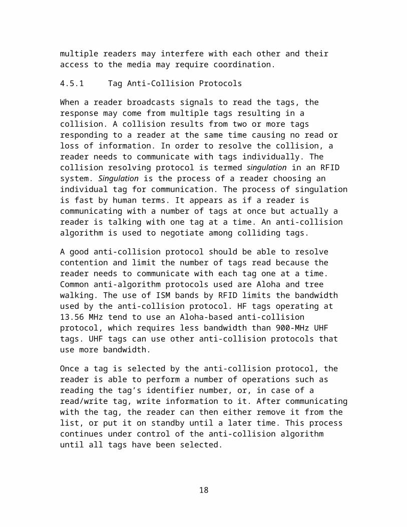
Figure 5. EPC format
9 EPC Tags
One option the Auto-ID Center had was to develop the numbering system and network infrastructure and use ISO protocols as the standard for the air interface. However, the Center developed its own UHF protocol. Originally, it was planning to have one protocol that could be used to communicate with different classes of tags. EPCglobal has defined different classes of tags and they are shown in Table 4 [7], [8], [9], [10].
Table 4. Classes of tags
Class 0 Passive Read onlyClass 1 Passive Read only write onceClass 2 Passive 65 KB read-writeClass 3 Semi-passive 65 KB read-write with built-in batteryClass 4 Active Built-in batteryClass 5 Active Communicates with other class 5 tags and devices
The Auto-ID Center adopted a Class-0 tag, which was a read-only tag that was programmed at the time the microchip was made [8]. The Class-0 tag uses a different encoding from the Class-1 tag [9], which means that end users have to buy multiprotocol readers that implement Class-0 and Class-1 protocols to read both Class-1 and Class-0 tags. In 2003, the Auto-ID Center transitioned into two separate organizations. Auto-ID Labs at MIT and other universities around the world continued primary research on EPC technologies. EPC technology was licensed to the Uniform Code Council (UCC), which set up EPCglobal as a joint venture with European Article Number (EAN) International, to commercialize EPC technology. In September 2003, the Auto-ID Center handed off the Class-0 and Class-1 protocols to EPCglobal, and EPCglobal's board subsequently approved Class-0 [8] and Class-1 [9] as EPC standards.
In addition to not being interoperable, Class-1 and Class-0 tags have other shortcomings. One issue is that they are incompatible with ISO standards. Another issue is that they cannot be used globally. Class-0 tags, for instance, send out a signal at one frequency and receive a signal back at a different frequency within the UHF band; this is prohibited in Europe.
18

In 2004, EPCglobal began developing a Class-1 Generation-2 protocol (Class-1 Gen-2 or just Gen-2), which would not be backward compatible with either Class-1 Generation-1 (Class-1 Gen-1) or Class-0 tags [10]. The aim was to create a single, global standard that would be more closely aligned with ISO standards. Class-1 Gen-2 was approved in December 2004. RFID vendors that had worked on the ISO UHF standard also worked on Class-1 Gen-2 [20]. Class-1 Gen-2 was designed to be fast-tracked within ISO, but a last minute disagreement over an application family identifier (AFI) was likely to slow ISO approval. All ISO RFID standards have an AFI, an 8-bit code that identifies the origin of the data on the tag. Class-1 Gen-2 has an 8-bit block of code that can be used as an AFI, but it is not required under the standard. Requiring the eight bits to be used for an ISO AFI would have limited EPCglobal's control over EPCs. But vendors are making products based on the new Class-1 Gen-2 standard, which paves the way for global adoption of EPC technology in the supply chain.
9.1 EPCglobal UHF Class-0 Tag
The EPCglobal UHF Class-0 RFID tag is described in [8]. In [8], the physical layer reader-to-tag link, the physical layer tag-to-reader link, and data link layer medium access control (MAC) protocol are described. In the EPCglobal specifications, the term anti-collision protocol is used instead of MAC. The physical layer specifications describe the symbols, encoding, and modulation. The anti-collision protocol coordinates communication from one or more tags to the reader and the communication from the reader to one or more tags. The tag-to-reader anti-collision protocol tends to be the most important because it is assumed that readers can coordinate their communication. The anti-collision protocol for the Class-0 tags uses a binary tree walking anti-collision protocol operating at the OSI data link layer.
9.1.1 Physical Layer Reader-to-Tag Link
The reader-to-tag link baseband signal has a bit period ranging from 12.5 to 62.5 microseconds to create a fast to slow data rate. The reader-to-tag link uses an amplitude modulated (AM) carrier with either 100% or 20% modulation as shown in Figure 6. The 100% modulation is useful for short ranges and the 20% is for longer ranges because it provides more average power to the tag. In addition, in the U.S. the reader must perform frequency hopping every 50 to 400 milliseconds to conform to FCC regulations because it is operating in the UHF ISM band. Either frequency hopping or direct sequence spread spectrum can be used. The encoding method uses pulse width modulation (PWM) to send one of three symbols from the reader to the tag as shown in Figure 7. The width of the pulse specifies either a value of 0, 1, or a null symbol.
19

Reader RF signal, 100% modulation
Reader RF signal, 20% modulation
Figure 6. Reader-to-tag AM modulation [8]
Figure 7. Reader-to-tag symbols
20

9.1.2 Physical Layer Tag-to-Reader Link
The passive tags use modulated backscatter to send information to the reader. After the reader sends a command to query one or more tags the reader sends a continuous wave signal. The signal from the reader is modulated by the tag. The tag-to-reader link in a Class-0 tag uses two symbols consisting of two sub-carrier tones. The binary value of zero is represented by 2.25 MHz and the binary value of one is represented by 3.25 MHz. The tag modulates the reader’s signal by changing the chip port impedance and this is called modulated backscatter. Using two sub-carrier tones permits one bit of information to be sent from a group of tags to the reader without a collision. A collision occurs when the backscatter from two or more tags interfere with one another. If the reader receives a carrier modulated with 2.25 MHz, then it will know at least one tag backscattered a binary value of zero. If the reader receives a carrier modulated with 3.25 MHz, then it will know at least one tag backscattered a binary value of one. In both cases, the reader does not know how many tags answered and will have to use a singulation protocol to query an individual tag. Singulation is the process of a reader choosing an individual tag for communication.
9.1.3 Binary Tree Anti-Collision Protocol
The Class-0 tag uses a binary tree walking anti-collision protocol to share the medium among multiple tags [8]. It resolves contention, which is competition between one or more tags for access to the tag-to-reader link, and, at the bit level, is collision free. Recall that both a binary one and zero can be communicated from multiple tags to the reader because the values use two different sub-carrier tones. Consider the binary tree shown in Figure 8. Every EPC number is represented by the leaves of the tree. The root node is not considered part of the EPC number. Beginning at the root node the bit of each EPC number is represented by the nodes in the tree. The branches extending left of a node lead to a node representing a binary value of zero and the branches extending right of a node lead to a node representing a binary value of one. The least significant bit (LSB) is at the leaf end of the tree. Therefore, each bit of an EPC number can be found by traversing the tree beginning at the root and ending at a leaf node.
21

Figure 8. Binary tree representing the EPC number
The binary tree scanning anti-collision protocol may begin with the reader sending a subset of the total number of bits used for singulation to address a portion of the population of tags. The reader addressing a portion of the tags is used to issue global commands and for subdividing the population into a smaller population before performing the tree traversal. If more than one tag is selected by the reader, then the reader performs a binary tree traversal to negotiate with multiple tags and chooses a single tag for communication. The specification uses the term singulation to describe the negotiation. When doing a binary tree traversal the reader queries the tags one bit at a time. If the reader receives both a one and a zero it sends a command with either a binary one or a binary zero. If the tag receives an acknowledgment bit from the reader that is the same as the last backscattered bit, then it sends the next bit and stays active. Otherwise, the tag goes dormant during this round and does not send more bits unless instructed to by the reader. In this way, the binary tree is traversed so that the reader can singulate a tag.
9.1.4 Security of Class-0 Tag
Minimal security is implemented on the tag to reduce the cost. A 16-bit cyclic redundancy check (CRC) is used in a Class-0 tag to detect errors in the EPC of the tag [8]. The CRC is applied to the EPC number and stored on the tag. In addition, a 24-bit password is programmed into the tag during manufacturing. The password can be used to kill the tag. Once a reader accesses a tag with the correct 24-bit password and issues the kill command the tag no longer responds. It is implemented by causing a fusible link to become open on the tag. The option to kill a tag was in response to privacy proponents that were concerned that the privacy of individuals that purchase items would be jeopardized by items that can be uniquely identified [2]. The Auto-ID Center and later
22

EPCglobal responded to these complaints by including the option to kill a tag after purchase if a customer desires to protect their privacy.
One security concern with Class-0 tags is that the reader acknowledges responses of a tag bit by bit with an identifier that may be the EPC number when using the binary tree anti-collision algorithm. Therefore, the EPC number can be inferred from the reader signal that can be received at a much longer distance than the backscattered signal of the tag. The chosen identifier used for singulation is discussed below.
Class-0 tags can use one of three identifiers for singulation named ID2, ID1, and ID0. ID2 is the full EPC number plus the CRC and is used by default. ID1 is an identifier formed using a pseudo random number generated using a seed based on the CRC of the tag. ID0 is a random number that changes every time a tree traversal occurs.
9.2 EPCglobal UHF Class-1 Generation-1 Tag
The EPCglobal UHF Class-1 Generation-1 RFID tag (Class-1 Gen-1) is described in [9]. It is not backwards compatible with the Class-0 tags and therefore multi-protocol readers are required that switch between Class-1 Gen-1 and Class-0 protocols. A Class-1 Gen-1 tag contains an EPC, a cycle redundancy check (CRC) applied to the EPC for error detection, and a password.
9.2.1 Physical Layer Reader-to-Tag Link
The physical layer reader-to-tag link of a Class-1 Gen-1 tag uses the same type modulation and encoding method as a Class-0 tag. The data encoding uses PWM with an additional data symbol called punctuation.
9.2.2 Physical Layer Tag-to-Reader Link
The physical layer tag-to-reader link of a Class-1 Gen-1 tag uses a different encoding method than a Class-0 tag. It uses an encoding method named FM0. FM0 is described in the Class-1 Gen-2 section. It uses two transitions for binary value of zero and four transitions for binary value of one.
9.2.3 Tree Walking Anti-Collision Protocol
The anti-collision protocol for the Class-1 Gen-1 tag uses a form of tree walking like the binary tree walking protocol of a Class-0 tag. However, the reader can query tags using a mask, which is a group of bits instead of individual bits. If the bits of a tag match the mask, the tag responds with an 8-bit response during one of eight time slots that are specified by the reader. The 8-bit response is eight bits of the tag specified by the reader. The slots are numbered 0 to 7 and the tag responds in the time slot dependent on the first three most significant bits of the 8-bit response as shown in Figure 9.
23

Figure 9. Eight time slots for responses from tags
If there is a collision, the reader knows that more than one tag exists with this particular mask and extends the length of the mask to create a more specific query. In this way, a query tree can be built that determines the tags by the series of either no responses, single responses, or multiple responses (collisions) [19].
In a query tree protocol, the reader successively splits the tag population into groups to identify tags. However, it is sensitive to the distribution of tag EPCs. A query tree is a data structure for representing the mask sent by the reader and an example is shown in Figure 10. The query tree protocol proceeds in rounds. The reader sends a query for tags with a specified mask. If a tag answers, then it is acknowledged by the reader. If multiple tags answer, then a collision occurs and the reader knows that tags with that mask exist. Therefore, it increases the size of the mask on the next query to single out a tag. This continues over several rounds until all tags are identified.
Figure 10. Query tree
9.2.4 Security of Class-1 Gen-1 Tag
Like a Class-0 tag a Class-1 Gen-1 tag has a 16-bit CRC applied to the EPC and stored on the tag for error checking. In addition, there is a kill command but it is protected by an 8-bit password instead of the 24-bit password. Class-1 Gen-1 tags have a lock command. After the tag is locked the EPC, CRC, and password field cannot be modified. If the tag is
24

not locked, the tag can be erased, which sets all bits to zero. The specifications specify that the intended range that a reader can read a tag is at least 3 meters but less than 30 meters [9]
9.3 EPCglobal UHF Class-1 Generation-2 Tag
The EPCglobal UHF Class-1 Generation-2 RFID tag (Class-1 Gen-2) is significantly different than the Class-0 and Class-1 Gen-1 tags [10]. The physical layer reader-to-tag link uses one of three modulation techniques with pulse width modulation (PWM) encoding like Class-0 and Class-1 Gen-1 tags, although in [10] it is referred to as a pulse-interval encoding (PIE) format. The tag in the physical layer tag-to-reader link modulates the reader’s unmodulated RF carrier using backscatter modulation. The reader specifies the encoding format for the tag-to-reader link. The choices are either baseband FM0 or a Miller-modulated subcarrier. Instead of a tree walking anti-collision protocol, the anti-collision protocol for the Class-1 Gen-2 tags use a slotted Aloha-based random anti-collision protocol called the Q protocol. However, a tag population can be subdivided using commands to perform tree walking using a multiple bit mask as in Class-0 and Class-1 Gen-1 tags before performing the Q protocol. In addition, Class-1 Gen-2 tags support the concept of a session. The tags support four sessions so that two or more readers can independently inventory tag populations during an inventory round. Finally, Class-1 Gen 2-tags have enhanced security by supporting a method for obscuring the information sent from the reader to the tag.
9.3.1 Physical Layer Reader-to-Tag Link
The physical layer reader-to-tag link uses double-sideband amplitude shift keying (DSB-ASK), single-sideband amplitude shift keying (SSB-ASK), or phase-reversal amplitude shift keying (PR-ASK) [10]. The passive tags operate using the energy of the reader’s RF carrier. The data encoding format is called pulse-interval encoding (PIE), which is like the Class-0 reader-to-tag link. The high value represents a continuous wave (CW) RF carrier and the low value represents an attenuated CW. The reader-to-tag link and tag-to-reader link must be half-duplex to adhere to regulations in certain parts of the world. Half-duplex is communications in both directions but only one at a time. In addition, the reader performs frequency hopping to conform to regulations.
9.3.2 Physical Layer Tag-to-Reader Link
Class-1 Gen-2 tags use backscatter modulation to modulate the reader’s RF carrier in the physical layer tag-to-reader link. The reader specifies the encoding format. The two formats are FM0 or a Miller-modulated subcarrier. FM0 encoding is for obtaining high read rates in low-noise environments and the Miller-modulated subcarrier encoding is for isolating tag responses into side channels of varying widths so that the reader can isolate responses [26]. Note that Class-1 Gen-1 tags use FM0 encoding.
The two FM0 basis functions for encoding are shown in Figure 11. FM0 inverts the baseband value at the beginning of every bit period. The binary value of zero has a transition in the middle of the bit period. The binary value of one does not have a
25
transition in the middle of the bit period. Therefore, the transition or lack of transition in the middle of the bit period is used for encoding information. An example encoding of a binary sequence is shown in Figure 12.
Figure 11. FM0 basis functions
Figure 12. FM0 encoding of the binary sequence 1100
The two Miller basis functions for encoding are shown in Figure 13. The binary value of zero does not have a transition in the middle of the bit period. The binary value of one has a transition in the middle of the bit period. In addition, baseband Miller inverts the baseband value between adjacent binary values of zero. Finally, the resulting waveform is multiplied by a square wave of M subcarrier cycles per bit, where M is two, four, or eight as shown in Figure 14. The value of M is specified by the reader when it reads tags.
26

Figure 13. Miller basis functions
Figure 14. Miller encoding of the binary sequence 1100 with M=2
9.3.3 Q Protocol Anti-Collision Protocol
Readers cycle through the select, inventory, and access phases to manage populations of tags [10]. In the select phase, a particular tag population is selected. During the inventory phase, an individual tag is identified. Then, the reader enters the access phase to communicate with the individual tag.
In the select phase, readers can select tags specifying a pointer to tag memory, a length, and a mask. The mask is a string of bits. Only tags that have matching bits in the specified range answer the reader. The reader can send multiple select commands to perform unions, intersections, and negation set commands. Therefore, a reader can single
27

out one or more tags that match the selection criteria. This method can be used to perform a tree walking anti-collision protocol such as a query tree protocol as discussed in the Class-1 Gen-1 section.
During the inventory phase, the reader identifies an individual tag using the Q protocol, which is a slotted Aloha-based anti-collision protocol [10]. The reader creates slotted time in which all tags are to backscatter at the beginning of the slot, which is more efficient than permitting tags to backscatter in an unsynchronized way. The reader begins by sending the command Query to the tag population. The Query contains the parameter Q and the session number. Tags that belong to the requested session pick a random value in the range [0, 2Q-1]. Tags that pick zero backscatter a 16-bit pseudo-random number (PRN) for singulation immediately. The 16-bit PRN is generated every session and used for singulation. The remaining tags may decrease their slot number depending upon future reader commands and backscatter when it reaches zero. Assuming that there is either no collision or the reader can resolve a unique 16-bit PRN tag response, the reader acknowledges an individual tag by sending the 16-bit PRN. Then the chosen tag backscatters its EPC and 16-bit CRC. The reader then sends either a QueryAdjust or a QueryRep command and the identified tag changes its inventoried flag from either A to B or B to A. The QueryAdjust repeats a previous Query and may send a new value of Q in order to sort out collisions. Tags that have not been inventoried in this session use the new value of Q and pick another random number. The QueryRep command repeats a previous Query with the same Q parameter. Tags that have a nonzero slot number decrease their value every time the reader sends a QueryRep command and backscatter a 16-bit PRN when the number reaches zero. The parameter Q is in the range [0, 15] and the suggested beginning value is four. In this way, the reader queries multiple tags in a session and can vary the parameter Q to regulate the probability of tag responses. Note that the tag must have a slot counter and be able to generate a 16-bit PRN.
The reader interacts with an individual tag during the access phase after acknowledging it using the 16-bit PRN. The commands from the reader use the 16-bit PRN as a handle during the communication. The tag is to verify the handle perform performing any commands. Any commands that contain an invalid handle are ignored. The handle is the same during the access phase.
9.3.4 Sessions
The Class-1 Gen-2 tags incorporate a way for multiple readers to independently inventory the same population of tags [10]. Each tag has four sessions S0, S1, S2, and S3. Each session has an independent inventoried flag that has two values labeled A and B. This inventoried flag can be switched from A to B or B to A by a command from the reader. For example, assume that there are two readers, reader 1 and reader 2. The readers take turns querying a single population of tags. Reader 1 goes first. It sets the inventoried flag of all tags in session S2 to B. Then it inventories the tags in session S2 with inventoried flag B and sets the flag to A. Then reader 1 shuts off. Reader 2 sets the inventoried flag of all tags in session S3 to A. Then reader 2 inventories the tags in session S3 with inventoried flag A and sets the flag to B.
28

9.3.5 Security of Class-1 Gen-2 Tag
A 16-bit CRC is applied to the EPC for error detection [10]. In addition, a 16-bit CRC is used for error detection on certain reader-to-tag commands and certain tag-to-reader responses. Class-1 Gen-2 tags have a 32-bit kill password [10]. The default value for a tag is all zeros and tags will not execute the kill command if the password is set to all zeros. If the tag has a nonzero password and the reader supplies the password then the tag will execute the kill command, which permanently disables the tag.
Class-1 Gen-2 tags have the ability to generate a 16-bit random or pseudo-random number (PRN) [10]. The 16-bit number is used to create a handle during singulation instead of using the EPC number, to encrypt reader-to-tag link communication, and to determine the number of slots to wait in the Q protocol. The 16-bit PRN is used during the inventory phase as a unique identifier that the reader is to acknowledge. Using a random number enhances security by obscuring the identity of the tag.
The random number is sent from the tag to the reader unencrypted. Therefore, the random number may be intercepted by an attacker. However, the tag-to-reader link is much weaker (80-90 dB) than the reader-to-tag link, which reduces the probability that it can be intercepted. This is a trade-off between security and the cost of the tags. The write, kill, and access commands from the reader to the tag obscure the communication with a one-time pad using a 16-bit PRN from the tag. The reader requests a 16-bit PRN from the tag. The tag responds with the 16-bit PRN. The reader then encrypts the commands by performing a bit-by-bit exclusive OR (EXOR) using the 16-bit PRN. The tag decrypts the commands with the same 16-bit PRN.
29

PART III
RFID SECURITY AND THREATS
10 RFID Threats
RFID technology is quickly evolving in the supply chain because it increases visibility of the movement of supplies providing opportunities to increase efficiency. It enables access to hidden and useful information on the locations of tagged products. Manufacturers, suppliers, and retailers will benefit from RFID by increased competitiveness. Consumers will enjoy better service and enhanced selection. These benefits will require a complex system.
The vision of the standard proposed by EPCglobal is a standardized system running on different platforms with a standardized protocol. It builds on existing technologies such as servers, clients, databases, wireless communication, and Internet protocols each with its own vulnerabilities. RFID will further enable automated decision making and synchronization of information between businesses. Privacy and security issues should be addressed before RFID implementations will be accepted universally. How secure is an RFID system? What kind of privacy does RFID provide to the owner of a tagged product? These two questions need to be answered.
RFID system is no-contact and non-line-of-sight identification, which is different from ubiquitous barcode identification system [17]. Hence, it is difficult to completely stop the signals from being emitted from the tags. Tags are placed on pallets, cases, and individual items and can be scanned from between inches to meters, revealing the EPC number. The EPC number is the key to a database entry that contains information about the product and its owner. This will reduce purchase anonymity and privacy advocates are worried about disclosing such information.
Certain privacy issues did arise when Gillette Company decided to apply 500 million RFID tags from Alien Technology Corp. to its Mach III turbo razors [27]. Consumer privacy advocates criticized embedding RFID chips in merchandise products, fearing uncontrolled level of observation that makes users identifiable. Some critics like the head of the Consumers Against Supermarket Privacy Invasion and Numbering (Caspian) call for the global boycott of Gillette and Benetton after their plan to endorse RFID chips in their products [28]. Some consumers see those techniques as a marketing strategy to collect information about the interests of a customer; a retailer can send the related item’s coupons to customer’s houses and surprise them with their favorite items on sale. Many people do not want their interests to be disclosed.
Today, passive tags do not possess enough power and circuitry to send the information directly to the reader or to implement strong cryptographic encryption functions. An intruder with an intelligent reader can read and modify the tag’s contents like EPC number, because of the nonexistent or weak security. These security functions require a significant amount of processing power. Adding the necessary circuitry and power to the
30

passive tags adds undesirable cost. The EPC Class-1 Gen-2 tags do have enhanced security that was added to address some concerns but it may not be enough.
Functionality of a tag is easily increased by increasing its cost. But even these expensive tags are not considered safe and can be reverse engineered. Two students reverse engineered Texas Instrument’s DST transponder that is used in the anti-theft system of vehicles and for speed passes that permit a user to quickly buy gas [29]. They were able to start a vehicle with the cloned key and buy gas with a cloned RFID tag.
In this section, the threats to RFID will be categorized using a well-known model for designing software systems [30]. Threats are potential events that cause a system to respond in an unexpected or damaging way. The first step in building a secure system is to understand the threats [30]. It is useful to categorize threats to determine strategies for mitigating them. One way to categorize threats is called STRIDE [30]. STRIDE is an acronym for six threat categories that are listed below.
S poofing identity. Spoofing occurs when an attacker successfully poses as an authorized user of a system.
T ampering with data. Data tampering occurs when an attacker modifies, adds, deletes, or reorders data.
R epudiation. Repudiation occurs when a user denies an action and no proof exists to prove that the action was performed.
I nformation disclosure. Information disclosure occurs when information is exposed to an unauthorized user.
D enial of service. Denial-of-service denies service to valid users. Denial-of-service attacks are easy to accomplish and difficult to guard against.
E levation of privilege. Elevation of privilege occurs when an unprivileged user or attacker gains higher privileges in the system than what they are authorized.
10.1 Spoofing Identity
Spoofing occurs when an attacker successfully poses as an authorized user of a system. Listed below are spoofing threats.
A competitor or thief performs an unauthorized inventory of a store by scanning RFID EPC tags with an unauthorized reader to determine the types and quantities of items. An unauthorized reader can query the tag for the EPC number because most tags used in the supply chain respond to any reader. The EPC number is only a number. However, because of the standard way of creating an EPC number, an attacker can determine the manufacturer and possibly the product number. It is likely that the number assigned to all manufacturers will become public knowledge as well as the product number after some short period of time.
An attacker determines what organization is assigned an EPC number by posing as an authorized ONS user. An attacker can pose as an authorized ONS user and submit queries of either gathered EPC numbers or random EPC numbers to ONS. Middleware queries ONS with the EPC number to determine the URL of the
31

database that contains information on this particular EPC number. If an attacker can pose as one of the authorized middleware users, s/he can submit queries and gather URLs determining the location and possible identification of the organization that contains information on the EPC number.
An attacker determines the complete information about an object by posing as an authorized user of the database referenced by ONS. An attacker can pose as an authorized ONS user and submit queries to ONS gathering URLs and then look up the EPC number in the appropriate database after being authenticated. A user of ONS authenticates itself with the database after finding the location of the database with ONS to find the mapping between the EPC number and information about the product that has the tag. An attacker that poses as an authorized user can determine the manufacturer, product description, and serial number of a case or a large number of cases.
An attacker poses as an ONS server. It can gather EPC numbers quietly or respond with invalid URLs leading to either a tampering of data or a denial-of-service attack.
10.2 Tampering with Data
Data tampering occurs when an attacker modifies, adds, deletes, or reorders data. Listed below are data tampering threats.
An attacker modifies a tag.
o An attacker modifies the tag in a passport to contain the serial number associated with a terrorist or criminal.
o A terrorist or criminal modifies a passport tag to appear to be a citizen in good standing.
o An attacker modifies the EPC number on tags in the supply chain, warehouse, or store disrupting business operations and causing a loss of revenue. An attacker could ship a rogue reader that periodically comes on while being shipped. Or the attacker could walk through a store.
o An attacker modifies a high-priced item’s EPC number to be the EPC number of a lower cost item.
An attacker adds a tag to an object.
o An attacker adds a tag in a passport that contains the serial number associated with a terrorist or criminal.
o An attacker adds additional tags in a shipment that makes the shipment appear to contain more items than it actually does.
32

An attacker deletes data on a tag.
o An attacker kills tags in the supply chain, warehouse, or store disrupting business operations and causing a loss of revenue [31]. EPCglobal proposed that a tag have a “kill” command to destroy it to protect consumer privacy. If implemented in the tag, an attacker can “kill” the tag if the password is known. Class-0, Class-1 Gen-1, and Class-1 Gen-2 tags have kill commands [8], [9], [10]. An attacker could ship a rogue reader that periodically comes on while being shipped. Or the attacker could walk through a store.
o An attacker erases the tags setting all values including the EPC number to zero in the supply chain, warehouse, or store disrupting business operations and causing a loss of revenue. An attacker could ship a rogue reader that periodically comes on while being shipped. Or the attacker could walk through a store.
o An attacker removes or physically destroys tags attached to objects [29]. This is used by an attacker to avoid tracking. A thief destroys the tag to remove merchandise without detection.
An attacker reorders data on a tag or reorders tags.
o An attacker exchanges a high-priced item’s tag with a lower-priced item’s tag. Barcodes have been subject to this attack for years.
An attacker modifies the return signal from the tag to the reader.
An attacker poses as an ONS server and responds with the incorrect URL in response to an ONS query from a manager.
An attacker modifies, adds, deletes, or reorders data in a database that contains the information about EPC numbers. This is under the category of database security.
10.3 Repudiation
Repudiation threats occur when a user denies an action and no proof exists to prove that the action was performed. Listed below are repudiation threats.
A retailer denies receiving a certain pallet, case, or item. A non-repudiation protocol is required to ensure that neither the sender nor the receiver can deny actions.
The owner of the EPC number denies having information about the item to which the tag is attached. This could lead to a user being denied warranty repair or returns.
33

10.4 Information Disclosure
Information disclosure occurs when information is exposed to an unauthorized user. It is a threat to privacy if it is information about an individual. Listed below are information disclosure threats.
A bomb in a restaurant explodes when there are five or more Americans with RFID-enabled passports detected.
A smart bomb positioned at a street corner explodes when a particular individual with an RFID-enabled passport is detected.
A smart bomb positioned at a street corner explodes when an individual carrying one or more specific items with tags is detected. An individual could be marked by reading the tags that they typically carry. Or any individual buying certain products could be marked.
A mugger marks a potential victim by querying the tags in possession of an individual to determine if they are carrying valuable or wanted items.
An attacker blackmails an individual for having certain merchandise in their possession.
A fixed reader at a retail counter identifies the tags of a person and shows the similar products on the nearby screen to a person to provide individualized marketing.
A competitor or thief performs an unauthorized inventory of a store by scanning tags with a reader to determine the types and quantities of items. An unauthorized reader can query the tag for the EPC number because most tags used in the supply chain respond to any reader. The EPC number is only a number. However, it is an index and there are standards ways of creating them. Because of the standard way of creating an EPC number, an attacker can determine the manufacturer and possibly the product number. It is likely that the number assigned to all manufacturers will become public knowledge as well as the product number after some short period of time. A competitor gains information on the types and quantities of items in a store. A thief could query a warehouse, truck, or store to help locate high-priced items.
A thief creates a duplicate tag with the same EPC number and returns a forged item for an unauthorized refund.
A sufficiently powerful directed reader reads tags in your house or car.
10.5 Denial of Service
Denial-of-service denies service to valid users. Denial-of-service attacks are easy to accomplish and difficult to guard against. Listed below are denial-of-service threats.
34

An attacker kills tags in the supply chain, warehouse, or store disrupting business operations and causing a loss of revenue [31]. EPCglobal proposed that a tag have a “kill” command to destroy it to protect consumer privacy. If implemented in the tag, an attacker can “kill” the tag if the password is known. Class-0, Class-1 Gen-1, and Class-1 Gen-2 tags have kill commands [8], [9], [10]. An attacker could ship a rogue reader that periodically comes on while being shipped. Or the attacker could walk through a store.
A shoplifter carries a blocker tag that disrupts reader communication to conceal the stolen item [31]. The blocker tag is used against the tree walking anti-collision protocols. An attacker can simulate many RFID tags simultaneously causing the anti-collision to perform singulation on a large number of tags making the system unavailable to authorized use [31]. Singulation is the process in the deterministic anti-collision protocol of systematically choosing one tag to respond. Plans for a blocker tag already exist [31]. A blocker tag is a cheap passive RFID device that simulates many ordinary RFID tags simultaneously and renders specific zones to be private or public. The blocker tag could simulate all RFID tags or it could simulate portions of the EPC address space.
An attacker carries a special absorbent tag that is tuned to the same frequencies used by the tags. Instead of switching the impedance in and out of the antenna to modulate the reader signal it would just absorb the energy reducing the amount of reader energy. It could be a passive device. This would decrease the amount of energy available for reading other normal tags.
An attacker removes or physically destroys tags attached to objects [31]. This is used by an attacker to avoid tracking. A thief destroys the tag to remove merchandise without detection.
An attacker shields the tag from being read with a Faraday Cage [31]. A Faraday Cage is a metal enclosure such as a bag lined with aluminum foil that prevents the reader from reading the tag. In the debate over embedding tags in passports, it has been suggested that the passports be inserted into a foil holder to prevent this type of attack [32].
An attacker with powerful reader jams the reader by creating a more powerful return signal than the signal returned from the tags and thus making the system unavailable to authorized users [31].
An attacker performs a traditional Internet denial-of-service attack against the servers gathering EPC numbers from the readers.
An attacker performs a traditional Internet denial-of-service attack against ONS.
An attacker sends URL queries to a database causing it to do database queries and therefore denying access to authorized users.
35

10.6 Elevation of Privilege
Elevation of privilege occurs when an unprivileged user or attacker gains higher privileges in the system than what they are authorized. Listed below are elevation-of-privilege threats.
A user logging on to the database to determine product information can become an attacker by raising his/her status in the information system from a user to a root server administrator and write or add malicious data into the system.
36

11 References
[1] Intermec Technologies Corporation, “RFID overview”. Available: http://epsfiles.intermec.com/eps_files/eps_wp/IntroRFID_wp_web.pdf
[2] S. Garfinkel and B. Rosenberg, Eds., RFID: Applications, Security, and Privacy, Upper Saddle River, New Jersey: Addison-Wesley, 2006.
[3] T. Mital, “The emergence of RFID,” M.S. project, BAUER College of Business, University of Houston, Houston, Texas, 2003. Available: http://www.uhisrc.com/ FTB/RFID/RFID%20Sep03.pdf
[4] Richardson-Electronics, “RFID”. Available: http://www.ferret.com.au/Showcases/Richardson-Electronics/114211
[5] Webopedia, “RFID”. Available: http://www.webopedia.com
[6] RFID Survival homepage, “Savant and RFID”. Available: http://www.rfidsurvival.com/SavantandRFID.html
[7] 13.56 MHz ISM Band Class 1 Radio frequency Identification Tag Interface Specification: Candidate recommendation, ver. 1.0.0, tech. report, Auto-ID Center, MIT, Cambridge, MA, Feb. 1, 2003.
[8] Draft Protocol Specification for a 900 MHz Class 0 Radio Frequency Identification Tag, Auto-ID Center, MIT, Cambridge, MA, Feb. 23, 2003. Available: http://www.epcglobalinc.org/.
[9] 860 MHz – 930 MHz Class I Radio Frequency Identification Tag Radio Frequency & Logical Communication Interface Specification Candidate Recommendation, ver. 1.0.1, tech. report, Auto-ID Center, MIT, Cambridge, MA, Nov. 14, 2002. Available: http://www.epcglobalinc.org/.
[10] EPCTM Radio-Frequency Identity Protocols Class-1 Generation-2 UHF RFID Protocol for Communications at 860 MHz – 960 MHz, ver. 1.0.9, EPCglobal Inc., Jan. 31, 2005. Available: http://www.epcglobalinc.org/.
[11] “GDSN frequently asked questions,” FAQ’s, GS1, 2005. Available: http://www.ean-int.org/GDS/Documents/040615_faq_gds.pdf
[12] RFID Journal home page, “The basics of RFID technology”. Available: http://www.rfidjournal.com/article/articleview/1337/1/129/
[13] Intermec, “Supply Chain RFID: How it works and why it pays. Knowledgestorm”. [Online]. Available: http://knowledgestorm.de/shared/write/collateral/WTP/12482_93946_95071_Supply_Chain_RFID_White_Paper.pdf?ksi=1019489&ksc=1218727521
37

[14] D. Dressen, “Considerations for RFID Technology selection,” Atmel Applications Journal.
[15] Radio-Frequency-Identific@tion, “Frequencies for RFID-systems. Available: http://www.rfid-handbook.com
[16] K. Finkenzeller, RFID Handbook: Fundamentals and Applications in Contactless Smart Cards and Identification, R. Waddington, Trans., 2nd ed., Hoboken, New Jersey: John Wiley & Sons, 2003.
[17] S. E. Sarma, S. A. Weis, and D. W. Engels, “RFID systems and security and privacy implications,” in Proc. Workshop on Cryptographic Hardware and Embedded Systems (CHES), August 2002, pp. 454-470.
[18] B. Johanson and D. Byers, “An introduction to RFID-information security and privacy concerns,” Project, 2004.
[19] J. Myung and W. Lee, “An adaptive memoryless tag anti-collision protocol for RFID networks,” IEEE Annual Conference on Computer Communications (INFOCOM 2005), Poster Session, Miami, USA, March 2005.
[20] “A summary of RFID standards,” RFID Journal. Available: http://www.rfidjournal.com
[21] E. Schuman, “Do falling RFID prices mean item-level tracking is practical?,”CIO INSIGHT, September 15, 2003
[22] M. Roberti. (2003, September). “Analysis: RFID -Wal-Mart’s Network Effect. CIO INSIGHT”. [Online]. Available: http://cioinsight.com/article2 /0,1397,1455103,00.asp
[23] AIM. “RFID”. Available: http://www.aimglobal.org/technologies/rfid/what_is_rfid.asp.
[24] EPCglobal, “About the EPCglobal network”. Available: http://www.epcglobalinc.org
[25] EPCglobal, “The EPCglobal network: overview of design, benefits, & security,” September 24, 2004.
[26] “EPCglobal Class 1 Gen 2 RFID specification,” white paper, Alien Technology, CA, 2005.
[27] P. Clarke, “Start-up gets big order for fluidically assembled RFID chips,” EE Times, http://www.eet.com/news/latest/showArticle.jhtml?articleID=10800626
[28] A. Gilbert, “MIT bows out of controversial RFID tag research,” silicon.com, http://software.silicon.com/security/0,39024655,39116580,00.htm
38

[29] S. Bono, M. Green, A. Stubblefield, A. Juels, A. Rubin, and M. Szydlo. “Security analysis of a cryptographically-enabled RFID device,” in Proc. USENIX Security Symposium, July-August 2005.
[30] M. Howard and D. LeBlanc, Writing Secure Code 2nd ed., Redmond, Washington: Microsoft Press, 2003.
[31] A. Juels, R. Rivest, and M. Szydlo, “The blocker tag: selective blocking of RFID tags for consumer privacy,” in Proc. Conference on Computer and Communications Security - ACM CCS, October 2003.
[32] B. Schneier, “fatal flaws weakens RFID passports,” Wired NEWS, Nov. 2003, pp. 1- 2.
[33] C. Law, K. Lee, and K.-Y. Siu, Efficient Memoryless Protocol for Tag Identification, tech. report, Auto-ID Center, MIT, Cambridge, MA, Oct. 2000. Available: http://www.autoidlabs.org/whitepapers.
39