Embed Size (px)
Citation preview

1
Revisiting Aloha Airline Flight 243: Corrosion Engineer’s
Stand point
Submitted by
Mr Nauman Hashmi
School of chemical and materials engineering, National University of
Science and technology, Islamabad, Pakistan
Contact email: [email protected]
Contact number: 923335420262

2
Table of Contents
The Story of Aloha airline Flight 243 ......................................................................................... 7
Introduction ................................................................................................................................ 7
History of Aloha airline flight 243 ........................................................................................... 7
The Catastrophe Strikes.......................................................................................................... 8
Damage Details of the Airplane ............................................................................................. 9
History of the Airplane............................................................................................................ 13
The Boeing 737 Lap Joints Problem and its Dis-Bonding Issues ................................... 13
Aloha Airline Maintenance Record ...................................................................................... 19
Metallurgical Investigation ..................................................................................................... 20
NTSB Analysis ........................................................................................................................ 22
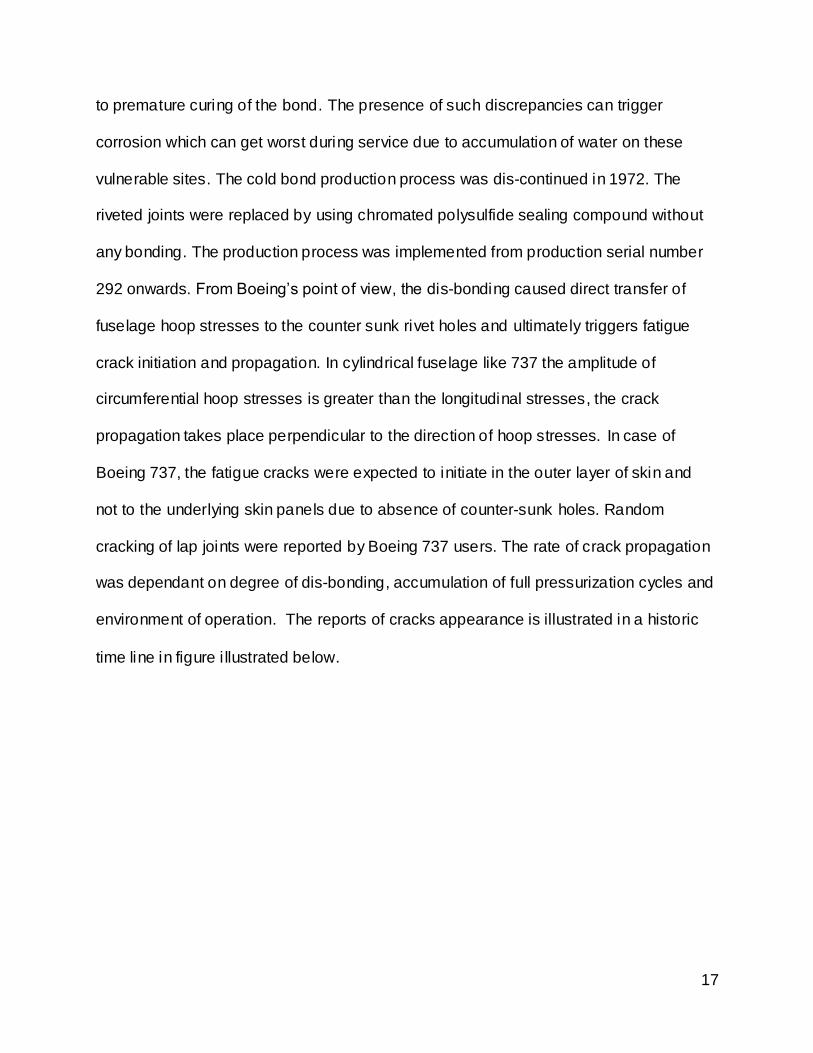
Corrective-preventive measures .......................................................................................... 24
Aviation Industry after Aloha Incident.................................................................................. 24
Synthesis ..................................................................................................................................... 26
The Contradictory Fluid Hammer Theory ........................................................................... 26
Analyzing Fluid Hammer Theory.......................................................................................... 30
Metal Fatigue or Corrosion Fatigue ..................................................................................... 31
A Corrosion Engineer’s investigation of Aloha flight 243 ................................................. 35

3
Aloha Airline Flight 243 failures from a Corrosion engineer stand point ....................... 40
Preventive measures to avoid recurrence.............................................................................. 40
Preventive Measure for Boeing’s manufacturing ............................................................... 40
Preventive Measure for Airline Operators .......................................................................... 42
Conclusion ................................................................................................................................... 42
Works Cited ................................................................................................................................. 43

4
List of Figures
Figure 1: Details of Causalities of Airline Flight 243 (Source: (National Transportation
Safety Board, 1989, p. 5) ............................................................................................................ 9
Figure 2: Schematics of Damage Cause to Aloha Airline Flight 243 (Source: (National
Transportation Safety Board, 1989, p. 6) ............................................................................... 10
Figure 3: Damage to the right hand side of Fuselage of Aloha Airline Flight 243 ........... 11
Figure 4: Damage to the Left Hand Side of Aloha Airline Flight 243 ................................. 11
Figure 5: Front view of Damaged Aloha Airline Flight 243 fuselage .................................. 11
Figure 6: Damage Direction between Body station 360 & 540 ........................................... 12
Figure 7: Section wise distribution of Boeing 737 Fuselage (Source: (National
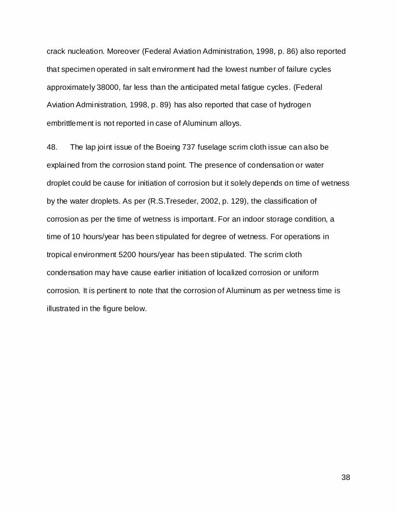
Transportation Safety Board, 1989, p. 6) ............................................................................... 14
Figure 8: Comparison fuselage structure for production serial number of Boeing 737
fuselage (Source: (National Transportation Safety Board, 1989, p. 15) ........................... 16
Figure 9: Historic Time line of Lap joints crack appearance on Boeing 737 fuselage
(Source: (National Transportation Safety Board, 1989, p. 19)............................................ 18
Figure 10: Frequency of Maintenance of Aloha airlines and others (Source: (National
Transportation Safety Board, 1989, p. 22) ............................................................................. 19
Figure 11: Number of cycles observed on different stringers (Source: (National
Transportation Safety Board, 1989, p. 31) ............................................................................. 21
Figure 12: Typical Crack Appearance on Lap joint (Source: (National Transportation
Safety Board, 1989, p. 32) ........................................................................................................ 21

5
Figure 13: Typical Crack origination site on Lap joint (Source: (National Transportation
Safety Board, 1989, p. 32) ........................................................................................................ 22
Figure 14: South West Airline Flight 812 with fractured skin on fuselage (Source:
(Boylan, 2011)............................................................................................................................. 25
Figure 15: Blood Stains photograph that forms the Basis of Austin's fluid hammer theory
(Source: (Austin, 2001)) ............................................................................................................ 27
Figure 16: Illustration of Austin's theory showing trapped Lansing at the onset of
separation .................................................................................................................................... 28
Figure 17: Sequence II of Austin's theory indicating rupture of upper lobe of section 43
....................................................................................................................................................... 28
Figure 18: Calculation performed by Matt Austin .................................................................. 29
Figure 19: Pressure Profile on Boeng 737 fuselage (Source: (D.Y.Jeong, 1995, p. 28))
....................................................................................................................................................... 32
Figure 20: Strain rate of row of rivets on lap joint (Source: (D.Y.Jeong, 1995)) .............. 33
Figure 21: Effect of Corrosion on crack length (Source: (Craig L. Brooks, 1998, pp. 14-
10))................................................................................................................................................ 34
Figure 22: Pourbaix Diagram of Aluminum (Source: (American Society of Materials,
1995, p. 1428)) ........................................................................................................................... 35
Figure 23: Pitting Corrosion mechanism in Aluminum alloys (Source: (Vargel, 2004, p.
116)) ............................................................................................................................................. 36
Figure 24: Precipitation of a cathodic phase on grain boundaries (Source: (Vargel, 2004,
p. 125) .......................................................................................................................................... 37

6
Figure 25: Classification of Corrosion severity with respect to Aluminum wetness time
(Source: (R.S.Treseder, 2002, p. 131)) .................................................................................. 39
Figure 26: Boeing Lap joint design and proposed point of protection ............................... 41

7
Revisiting Aloha Airline Flight 243: Corrosion Engineer’s
Stand point
The Story of Aloha airline Flight 243
Introduction
1. From the Latin word of “Corrodere”, the word of corrosion has been derived
which means “gnaw into pieces”. Despite the rapid pace of human society since last 3
centuries, the silent attack of corrosion has been a problem. From giant engineering
structures till sewer pipe line, the battle between rust and run is on since the industrial
revolution. Corrosion has been the main factors of many technological and structural
disasters. From catastrophes of bridge collapse, pipe line explosion and aerospace
structures, almost all of the industries have born the burst of this silent enemy. In
preceding text, a similar catastrophe of fateful aloha airline flight 243 has been
discussed in detail.
History of Aloha airline flight 243
2. According to (National Transportation Safety Board, 1989, p. 1), on April 28,
1988 a Boeing 737 from Hawaii based Aloha Airlines was scheduled for many
interisland flights to different Hawaii destinations. From 0500 hours till 1100 hours, the
aircraft had flown six interisland uneventful flights.
3. As per (National Transportation Safety Board, 1989, p. 2), at 1325 hours flight
243 was ready to depart from Hilo, Hawaii to Honolulu, Hawaii. Two pilots, three flight
attendants and a Federal Aviation Authority (FAA) observer was the part of the flight

8
crew with 89 passengers on board. The departure and climb till cruise altitude were
uneventful.
The Catastrophe Strikes
4. As per (National Transportation Safety Board, 1989, p. 2), as the airplane was
leveled off to the cruising altitude of 24000 Feet AGL, both pilot heard a clap or
whooshing sound followed by wind noise behind them. The captain of the aircraft
observed that “there was blue sky where the first class ceiling had been”. The captain
immediately took control and started the descent. Due to ambient noise in the cockpit, it
was impossible to communicate.
5. At the onset of the decompression flight attendant no 1 was standing at seat row
5 and was swept away by the blowing wind from left side of the fuselage. The no 2 flight
attendant was standing at the row 15/16 and was thrown to floor. She sustained few
minor bruises. While no 3 flight attendant was standing at row 2, she was struck by the
debris and thrown to floor. She sustained serious head injuries.
6. According to (National Transportation Safety Board, 1989, p. 3), the first officer
radioed to the Honolulu air traffic controller about the emergency and also informed the
alternate Maui airport air traffic control for an emergency landing. The aircraft was
becoming uncontrollable below the speeds of 170 Knots and flap retraction above 5.
The captain decided to maintain the speed and flap retraction to attempt a landing on
Maui Airport. The landing gears were selected down but no indication of nose landing
gear was acknowledged by the flight crew. However visual check from the air traffic

9
control confirmed the lowering of nose landing gear. The aircraft landed at 1358 hours
on Maui Airport. The Causalities details is Illustrated below.
Figure 1: Details of Causalities of Airline Flight 243 (Source: (National Transportation
Safety Board, 1989, p. 5)
Damage Details of the Airplane
7. As per (National Transportation Safety Board, 1989, p. 5), a major portion of
upper crown skin and structure of section 43 separated in flight causing an explosive
decompression of the cabin. From NTSB stand point, explosive decompression in this
case refers to violent expansion and noise from cabin air released under pressure
rather than the effect of a chemical explosive device. From (National Transportation
Safety Board, 1989, p. 5) point of view, the damaged area extended from aft of main
cabin entrance door, rearwards about to 18 feet to the area just forward of the wing and
from left side at the cabin floor level to the right side window level. The airplane was
worth at an estimated cost of 5 million US dollars. As a result of accident it was
determined as damaged beyond economic repair and was dismantled and sold in
scraps and parts. The visual illustrations of the damage are depicted below in the
figures.

10
Figure 2: Schematics of Damage Cause to Aloha Airline Flight 243 (Source: (National
Transportation Safety Board, 1989, p. 6)

11
Figure 3: Damage to the right hand side of Fuselage of Aloha Airline Flight 243
Figure 4: Damage to the Left Hand Side of Aloha Airline Flight 243
Figure 5: Front view of Damaged Aloha Airline Flight 243 fuselage
Visual Examination

12
8. As per (National Transportation Safety Board, 1989, pp. 8-10), the skin of the
aircraft from body station 360 till body station 540 was peeled from the structure in down
and aft direction. The direction of damage on aircraft station is illustrated below in the
figure.
Figure 6: Damage Direction between Body station 360 & 540
9. According to (National Transportation Safety Board, 1989, p. 9), indications of
pre-existing cracks were found in lap joints of S-10L forward of body station 540 and on
side of each rivet holes in body station 360 butt strap near S-7R. All other fractures
adjacent to the separation area were typical of overstress application.
10. As per (National Transportation Safety Board, 1989, p. 10), fracture surface and
the immediate areas surrounding the separation perimeter were generally corrosion
free. However, areas of corrosion and dis-bonded surface were noted in joints at body
station 360 and 540.

13
History of the Airplane
11. According to (National Transportation Safety Board, 1989, p. 12), the mishap
aircraft N73711 was a Boeing 737-297 with serial number 20209. It was manufactured
in 1969 as production line number 152. It was equipped with two Pratt & Whitney JT8D-
9A engines. The airplane was delivered to Aloha Airlines on 10 May, 1969. The Aloha
Airline was operating eleven jets, all of them were Boeing 737s with flight cycles of
60000 or more.
12. As per (National Transportation Safety Board, 1989, p. 12), at the time of
accident, the jet N73711 has accumulated 35496 flight hours and 89680 flight cycles
(Landings). The airplane was the 2nd highest in number of operating cycles. The actual
operating flight cycles of the airplane was less than the stipulated number, as the
airplane never reached the maximum pressure differential of 7.5 PSI. The maintenance
log books of the airplane did not revealed any discrepancy prior to the accident.
The Boeing 737 Lap Joints Problem and its Dis-Bonding Issues
13. According to (National Transportation Safety Board, 1989, p. 13), the fuselage
structure of Boeing 737 comprises of four sections. The section 41, 43 and 46
formulates the most of pressurized area. These sections are joined with section 48 by
butt joints forming the complete fuselage. The section wise distribution of the Boeing
737 structure is illustrated below.
14
Figure 7: Section wise distribution of Boeing 737 Fuselage (Source: (National
Transportation Safety Board, 1989, p. 6)
14. The sections are constructed of circumferential frames and longitudinal stringers
that are covered by formed aluminum skin panels that are riveted to the underlying
structure. Each skin panel on the lobe of section 43 is the length of entire section that is
18 Feet. Adjacent skin panels are joined together by overlapping the panel about 3
inches over the lower panel. The joint area is fastened with three rows of rivet and a
bonding process.
15. As per (National Transportation Safety Board, 1989, p. 14), in Section 43 the skin
panel lap joints exists at S-4L & R, S-10L & R and S-14L & R at the upper lobe.
Similarly lap joints exist at S-19 L & R and S-26 L & R at the lower lobe. The upper lobe
skin panels in section 43 are fabricated from two complete sheets of 0.036 inch thick
aluminum that are joined together using a hot bonding process. An acid etch is used to
prepare the surfaces of sheets before bonding. The inner sheet is then masked and
then chemically milled leaving the waffle doublers that provides circumferential tear
straps at each 10 inch intervals. On the early production model (till serial number 291),

15
the doubler sheet was milled away chemically at lap joints location. While for production
serial number 292 and onward, the doubler sheet was retained to provide an extra
thickness. For earlier production serial number (1-291), the fuselage skin lap joints were
cold bonded. The cold bond process used an epoxy impregnated woven scrim cloth to
join the single thickness 0.036 inch skin panel together. The joints were mechanically
fastened by three rows of counter sunk rivets. The metal surface to be bonded was
etched to ensure cleanliness and prepare the surface for suitable bonding. The epoxy
used was reactive at room temperature and was kept in storage with dry ice and was
warmed till room temperature before use.
16. According to (National Transportation Safety Board, 1989, p. 14), the cold bond
process was intended to provide structural efficiency, manufacturing cost advantage
and overall reduction in weight over traditionally riveted thick skin panels. Fuselage
pressurization load was intended to be transferred through the cold bond rather than the
rivets, thus overall not having any impact on fatigue life of the structure. A comparative
lap joint construction for production serial number 1-291 and 291 onwards is illustrated
below in the figure.

16
Figure 8: Comparison fuselage structure for production serial number of Boeing 737
fuselage (Source: (National Transportation Safety Board, 1989, p. 15)
17. As per (National Transportation Safety Board, 1989, p. 18), the laboratory
coupon tests and Quonset hut test of full scale fuselage model conducted by Boeing
revealed no abnormality regarding the reliability of the cold bonded lap joints. However,
the early service history records of Boeing 737 revealed that difficulties were
encountered during this bonding process. From Boeing’s point of view the problem of
bonding degradation was either due to presence of condensation in scrim cloth or due
17
to premature curing of the bond. The presence of such discrepancies can trigger
corrosion which can get worst during service due to accumulation of water on these
vulnerable sites. The cold bond production process was dis-continued in 1972. The
riveted joints were replaced by using chromated polysulfide sealing compound without
any bonding. The production process was implemented from production serial number
292 onwards. From Boeing’s point of view, the dis-bonding caused direct transfer of
fuselage hoop stresses to the counter sunk rivet holes and ultimately triggers fatigue
crack initiation and propagation. In cylindrical fuselage like 737 the amplitude of
circumferential hoop stresses is greater than the longitudinal stresses, the crack
propagation takes place perpendicular to the direction of hoop stresses. In case of
Boeing 737, the fatigue cracks were expected to initiate in the outer layer of skin and
not to the underlying skin panels due to absence of counter-sunk holes. Random
cracking of lap joints were reported by Boeing 737 users. The rate of crack propagation
was dependant on degree of dis-bonding, accumulation of full pressurization cycles and
environment of operation. The reports of cracks appearance is illustrated in a historic
time line in figure i llustrated below.

18
Figure 9: Historic Time line of Lap joints crack appearance on Boeing 737 fuselage
(Source: (National Transportation Safety Board, 1989, p. 19)
18. According to (National Transportation Safety Board, 1989, p. 20), Boeing issued
several service bulletins (SB’s) to address the issue. The earliest of which was issued in
May 13, 1970 under the heading of “Sealing of Cold Bonded structure for Corrosion
Protection” bearing SB 737-53-1017. A follow up SB, bearing number SB 737-53-1039
was issued on July 19, 1972 which addressed the area of lap joint corrosion and repair
in the first 291 produced planes. In 1974, a revision was issued which stated, “ In most
instances these areas are identified only after corrosion caused exterior bulges, cracks
on missing fasteners” and prolonged operations with de-lamination (dis-bonded) would
lead to fatigue cracking. The details of corrosion and fatigue inspections were also
stipulated. However, the Federal Aviation Authority (FAA) never classified it as
mandatory. In 1987, the status was upgraded to alert and was to be complied before

19
30000 landing or next 250 landings by the FAA. It is pertinent to note that these
instructions laid emphasis on S-4L & R particularly. As per these directives, eddy
current non destructive testing (NDT) was to be performed on the suspected areas.
Aloha Airline Maintenance Record
19. The maintenance schedule of Aloha Airline as per Boeing recommendations and
other operators is illustrated below in the figure.
Figure 10: Frequency of Maintenance of Aloha airlines and others (Source: (National
Transportation Safety Board, 1989, p. 22)
20. As per (National Transportation Safety Board, 1989, p. 23), from maintenance
record of Aloha Airlines, it was found that the airplane had undergone its A,B,C and D
level checks in 1987 and 1988. The D checks which deals with the fuselage skin and
framing was complied in 1987. A similar kind of D check regarding the inspection of
fuselage splices and stringers was complied in 1981. The D check inspection included
an FAA approved ¼ sampling which meant that D level checks have to be carried out
on ¼ airplanes of the fleet. In case of adverse findings, rest of the fleet has to be
inspected. In case of no abnormality at the normal 15000 hours if no adverse finding

20
has been found the same inspection has to be complied on 30000 hours. As per Aloha
airlines maintenance records, no adverse findings were recorded.
21. According to (National Transportation Safety Board, 1989, p. 24), once visual
inspection of airplane exterior was carried out. Considerable evidence of corrosion on
fuselage of the fleet was recorded. Swelling and bulging of skin, dished fastener heads,
pulled and popped rivets, blistering, scaling and flaking paints were observed on lap
joints of almost every plane. Aloha airline failed to produce any evidence of in pace
corrosion control program. As per Boeing’s instructions, extensive application of
corrosion inhibitors compounds, fasteners reapplication, airplane washing and buffing
and brightening of unpainted surface was a part of corrosion control program at
specified intervals.
Metallurgical Investigation
22. According to (National Transportation Safety Board, 1989, p. 30), the lap joint
sample S-4R between BS 360 and 420 was found having extensive fatigue cracking.
The longest crack was found to be of 0.27 inches. The entire cold bonded lap joint had
become dis-bonded. Light to moderate and severe corrosion was noticed on different
areas. The lap joint of S-4L from BS-727 to 747 and 847 and 867 also showed fatigue
cracking in the skin adjacent to rivet holes. The laboratory examination further revealed
that only a crack larger than 0.08 inch can be detected by stipulated eddy current
contrary to Boeing’s claim of 0.04 inch. Boeing also performed the striation counts on
seven crack samples. The data acquired from these counts is illustrated below in the
figure.

21
Figure 11: Number of cycles observed on different stringers (Source: (National
Transportation Safety Board, 1989, p. 31)
23. The typical lap joints and appeared crack are illustrated below in the figure.
Figure 12: Typical Crack Appearance on Lap joint (Source: (National Transportation
Safety Board, 1989, p. 32)
The typical crack origination site on the lap joint has been depicted below in the figure.
22
Figure 13: Typical Crack origination site on Lap joint (Source: (National Transportation
Safety Board, 1989, p. 32)
NTSB Analysis
24. According to (National Transportation Safety Board, 1989, p. 47), the accident
sequence initiated with the separation of the pressurized fuselage skin. This separation
led to an explosive decompression which further caused the separation of upper lobe of
section 43 of the cabin. The post accident examination of the structure revealed that the
remaining intact structure did not contain the origin of the failure. The main exhibit was
not recovered despite the extensive sea and ground search. The origins of failure were
deliberated on the basis of remaining structure and the air worthiness history of the
airplane. The available evidence suggested that the origin of the fuselage separation
was initiated from lap joint S-10L near BS-440. NTSB also concluded that the tear strap
dis-bonding also resulted in failure of expected controlled decompression of the airplane
which was anticipated by designers. The multiple sit damage (MSD) also resulted in
multiple cracks. The dis-bonding of cold lap joints would result into transfer of loads

23
directly to the counter sunk rivets holes. The presence of knife edge in these rivet holes
would result in to a stress concentration area making it susceptible to fatigue cracking.
25. According to (National Transportation Safety Board, 1989, pp. 52-55), the Aloha
airline maintenance program did not realize the effect of flight cycle accumulation. The
maintenance program was based on flight hour’s accumulation rather than the flight
cycle accumulation. The maintenance program was further limited by time and man
power constraints and maintaining the operational status of the fleet. Moreover the
complied service bulletins of Boeing by Aloha airline did not had the documentary
evidence for compliance of NDT. The conduct of NDT on such portions of fuselage was
also difficult.
26. According to (National Transportation Safety Board, 1989, pp. 58-59), the
corrosion control program of Aloha airline was not as aggressive as it should have
been. The maintenance personnel’s seems to be unaware of the criticality of corrosion
on lap joints, tear straps and its adverse consequences. The maintenance record
established the fact that corrosion problem was detected by Aloha maintenance
personnel and the corrective actions were deferred without any sound reason.
27. As per (National Transportation Safety Board, 1989, pp. 73-74), the probable
cause of accident was failure of Aloha airline maintenance program to detect the
presence of significant dis-bonding and fatigue damage which ultimately led to the
failure of lap joint at S-10L and the separation of fuselage upper lobe. FAA also failed to
ensure the mandatory compliance of Boeing’s alert service bulletin regarding corrosion
and dis-bonding of lap joints.

24
Corrective-preventive measures
28. As per (National Transportation Safety Board, 1989, pp. 74-77), the FAA should
identify those operators which had significant difference in flight hour’s operation time
and flight cycle accumulation. They may be provided by the needed assistance for
maintenance programs. The programs of NDT certification and periodic skill
demonstration may be revised. FAA should also monitor the Boeing 737 jet fatigue
issues of lap joints. FAA should also develop model program for corrosion control for
airline operators. Full scale fatigue testing for at least two economic life cycles may be
included for future certifications and all those jets in operation may also be subjected to
subject testing’s.
29. NTSB also advised Aloha airline to revise its maintenance from cycle point of
view instead of flight hours. Aloha airlines were also advised to initiate an aggressive
corrosion control program. Aloha was also advised to upgrade its technical division on
professional grounds.
Aviation Industry after Aloha Incident
30. The Aloha airline incident was considered as a game changer for the airline
industry. The vulnerability of earlier production Boeing 737’s lap joint is area under
debate for decades after the accident. Boeing has incorporated many modifications and
steps to enhance and beef up the weak area. However, as per (Norris, 2011), on April 4
,2011 Boeing issued a service bulletin to all airline operators for inspecting the lap joints
on planes built between 1993-2000. The life cycle of 175 affected planes is greater than
30000 flight cycles. Boeing expected cracks appearance at around 60000 flight cycles.
According to (Boylan, 2011), the inspection was triggered by an in-flight fracture of

25
fuselage skin panel on South West Airline Flight 812. As per (Dubios, 2011), Boeing has
further reduced the inspection cycle to 30000 flight cycles.
Figure 14: South West Airline Flight 812 with fractured skin on fuselage (Source:
(Boylan, 2011)
31. The recurrence of the problem despite many corrective actions after the Aloha
airline incident has triggered a new debate. The core topics of debate would raise
questions on the failure mechanism of the Aloha airline flight 243 and further to the
steps to avoid the future recurrence. It has been felt imperative to re-visit the findings
and conclusion of Aloha airline Flight 243. Special emphasis has to be laid on the failure
mechanism and it’s in depth analysis. The contradictory theory of fluid hammer may
also be taken into account to ascertain its contribution in the failure.

26
Synthesis
The Contradictory Fluid Hammer Theory
32. The disaster of Aloha airline flight 243 has opened new debate on the fail safe
design of Boeing 737. As per Boeing’s claims a small hole in the fuselage would result
into a controlled decompression of the airplane. The controlled decompression would
not allow an explosive decompression and enhances the chance of survivability of
passengers. For this purpose, the tear straps are incorporated throughout the whole
fuselage structure. These tear straps allows the controlled decompression. The biggest
question in case of Aloha airline flight 243 was regarding the functionality of Boeing’s
tear strap mechanism. From NTSB point of view, the fatigue cracks within the skin also
cause fracture of tear straps, thus impeding their function to act as controlled
decompression points. However, as per (Stoller, 2001), a Hawaiian steam engineer
Matt Austin had others ideas regarding the crash of Aloha airline flight 243 and failure of
Boeing’s Tear strap mechanism. Austin is a former Hawaiian boiler expert and runs a
consultancy business.
33. According to (Austin, 2001), the failure of Aloha airline flight 243 was due to what
he termed as a fluid hammer theory. Austin has derived his hypothesis on the basis of a
blood stained picture from the NTSB investigation. The blood stained photograph that
formulates the basis of Austin’s theory is illustrated below.

27
Figure 15: Blood Stains photograph that forms the Basis of Austin's fluid hammer theory
(Source: (Austin, 2001))
34. According to (Austin, 2001), these blood stains are a tell tale story of what might
had happened at Aloha airline flight 243. These stains were actually the silhouette of the
only casualty of the flight, C B Lansing’s skull. From Austin’s point of view, these stains
are not explained properly in the inquiry and are misunderstood. Due to these reasons
the NTSB investigation cause is out rightly wrong. From Austin’s point of view, the
separation sequence started at BS 500 instead of BS 340. The flight attendant standing
at row 5 was sucked in the tear opening, blocking the controlled decompression. This
blockage led to the increase of the pressure inside the hull and eventually its failure. A
pictorial illustration of Austin’s theory is illustrated below.

28
Figure 16: Illustration of Austin's theory showing trapped Lansing at the onset of
separation
Figure 17: Sequence II of Austin's theory indicating rupture of upper lobe of section 43
35. Austin’s fluid hammer comes from the boiler’s back ground. It looks much
appealing in explaining the failure of tear strap mechanism. But NTSB had shown not

29
much interest to buy Austin’s idea. The calculation performed by Austin to validate his
fluid hammer theory is illustrated below in the figure.
Figure 18: Calculation performed by Matt Austin

30
Analyzing Fluid Hammer Theory
36. Before going further into details of NTSB investigation, it has been felt imperative
to analyze the Mat Austin’s fluid hammer theory. It is pertinent to note that the
calculations performed by Austin are as per the ideal gas law. From a static structure
like boilers, these calculations may stand valid, but from an aeronautical stand point
there synthesis is felt imperative.
37. According to (Mccormick, 1995, p. 26), the flow around an aerofoil is two
dimensional. As per (Megson, 1999, p. 220), the aircraft structures are designed to take
two types of loads, the ground loads and air loads. These loads can be further classified
into surface loads like aerodynamic and hydrostatic pressure and body forces due to
gravitational and inertial effects. According to (Swnginnis, 2003, p. 332), the aircraft
structures directly exposed to dynamic pressure could be damaged as the dynamic
pressure of the air stream is converted into static pressure pressing inward on the
structure. In case of Aloha airline flight 243 once the separation started due to cracks
and skin peeling off, it opened a hole which allowed gust of high velocity winds. This
high velocity winds when entered the cabin becomes stagnant and according to
(Swnginnis, 2003, p. 341), the sum of static pressure and dynamic pressure are equal
for an incompressible flow. The conversion of this huge dynamic pressure into static
pressure also increased the applied stress from within the fuselage structure. Moreover
these gust loads would have acted as impact loads on the internal structure. The value
of these loads probably had exceeded the limit loads of fuselage design. As fuselage
structures are not supposed to be accommodate any aerodynamic loads. Already
weakened structure by multiple cracks and corrosion gave way while the structure

31
having sufficient strength stood by. The rupture of the fuselage should not have any
impact on the lift. The lift distribution profiles on the aircraft fuselage are zero. However,
the subsequent damage caused by the debris might have damaged others lift
generating surfaces. That probably explains that why the aircraft still remained
controllable even after such a structural disintegration. The reason for difficulties above
the speeds of the 170 Knots might have been due to the reduced differential or hole in
structure probably would have disturbed the laminar flow. The local turbulence above
170 knots might have caused the controllability difficulty in higher speed regimes. The
fateful exit of C B Lansing had been probably due to this gust of wi nd. During her exit in
a turbulent flow, her head might have made contact with the left side of fuselage
causing the blood stained appearance of the side.
38. Mat Austin theory might have stand validated for a boiler or static system. But
impact loads due to gust of wind entering inside the fuselage from the initial rupture
could have been the sole cause of the structural dis-integration despite the presence of
tear straps.
Metal Fatigue or Corrosion Fatigue
39. According to (Schijve, 2004, p. 7), if a specimen is subjected to cyclic loads, a
microscopic fatigue crack could nucleate and grow till a macroscopic level, the final
cycle of fatigue crack could lead to fracture. From metal fatigue point of view, it is
pertinent to note that Boeing 737 had undergone the fatigue test and fatigue life
estimation. In case of Aloha airlines, the mishap aircraft had flown 89680 flight cycles.
Although the full pressurization (means a differential pressure of 7.5 psi) may not have
been applied on all the cycles, thus lowering the number of actual cycles operated.

32
Boeing had designed 737 for an economic life of 51000 flight hours and 75000 cycles .
The limit was further reduced to 60000 cycles after the crack reports on the structure.
The lowering of limits also could not stop the incident of South West Airline flight 812.
The recent reports of cracks are under a limit of 30000 flight cycles which is far below
then the prescribed limit. These recent problems raises the questions that either the
Boeing’s fatigue test of 737 has some serious issues or the problem exist somewhere
else. We will make an attempt to certify Boeing’s tests. According to (D.Y.Jeong, 1995,
p. 28), the pressure profile on the 737 fuselage is i llustrated below in the figure.
Figure 19: Pressure Profile on Boeing 737 fuselage (Source: (D.Y.Jeong, 1995, p. 28))
40. According to the experiments conducted by (D.Y.Jeong, 1995, p. 30), the highest
strain rate was experienced by top row of rivets. The graphical presentations of his
results are illustrated below in the figure.

33
Figure 20: Strain rate of row of rivets on lap joint (Source: (D.Y.Jeong, 1995))
41. This independent data indicates that Boeing’s claims of vulnerable area are
correct and the top most row of rivets is the susceptible one in case of fatigue cracking.
According to (R.J.H.Wanhill, 1999, p. 19), there is no primary association between
corrosion and fatigue. Severe corrosion did not result in multiple site damage (MSD).
However (Craig L. Brooks, 1998, pp. 14-12) suggests that the corrosion has
propounding effect on structural life. It can degrade the structural capabilities. His
experimental result also indicates the reduction in critical length of the crack under
aging effects. The graphical representations of his observations are i llustrated below.

34
Figure 21: Effect of Corrosion on crack length (Source: (Craig L. Brooks, 1998, pp. 14-
10))
42. It is evident from these results that the presence of corrosion had degraded the
structural capability to a considerable amount. The presence of corrosion is highly
dependent on the operating environment. In controlled laboratory environment the tests
may be misleading unless the operating environment is not simulated accurately. Aloha
airline flight 243 was operated in a marine environment. As per (R.S.Treseder, 2002, p.
146), the environment of Hawaii had an average PH of 8-8.3 with salinity between 34.6-
35, the content of dissolved oxygen in the environment is 6-14 ppm having a temprature
of 24-28 degree centigrade. The environment of Hawaii is one of the aggressive as
compared to other international marine environment. The absence of this environment
or a closer environment could lead to erroneous results. All these arguments indicate

35
that corrosion can degrade the fatigue life. Now it is imperative to find a corrosion
mechanism that can explain the catastrophe of Aloha airline flight 243.
A Corrosion Engineer’s investigation of Aloha flight 243
43. According to (Roberge, 2007, p. 34), corrosion failures are environmentally
context specific. As per (American Society of Materials, 1995, p. 1427), Aluminum is a
thermodynamically reactive metal but formation of a 1 Nano meter oxide film makes it
useful for the industrial application. The pourbaix diagram of Aluminum is illustrated
below.
Figure 22: Pourbaix Diagram of Aluminum (Source: (American Society of Materials,
1995, p. 1428))
44. According to (Vargel, 2004, p. 113), uniform corrosion is observed in aluminum in
high acidic or alkaline media. The problem arises due to solubility of thin oxide fi lm. The
operating environment of Aloha flight 243 was almost neutral with PH range between 8-
Region of
Operation in
Hawaii

36
8.3. Henceforth the chance of uniform corrosion in case of Aloha airline flight 243
seems remote.
45. As per (Vargel, 2004, p. 113), Aluminum is prone to localized or pitting corrosion
in near neutral environment. Pitting corrosion occurs when the metal is put into
permanent or intermittent contact with aqueous media. Experience shows that pitting
corrosion occurs during first week of exposure. Pitting corrosion is known to be
developed with Chloride ions. The operating environment of Aloha airline flight 243 had
a pretty higher concentration of salinity. The high content of salinity means higher
concentration of chloride ions making it more susceptible for corrosion. The mechanism
for pitting corrosion in Aluminum is illustrated below.
Figure 23: Pitting Corrosion mechanism in Aluminum alloys (Source: (Vargel, 2004, p.
116))
46. According to (Vargel, 2004, pp. 117-118), the rate of pitting corrosion decreases
with time. The pitting corrosion can be assessed using three criteria’s, which are the

37
density (number of pits/area), rate of deepening and probability of pitting. The rate of
deepening is more important than the density. As the deepening pit would determine the
service life of the structure. As per (Vargel, 2004, pp. 123-127), the corrosion
propagates either by intergranular means or by transgranular means. The transgranular
corrosion starts from a pit. There is not relationship between intercrystalline corrosion
and corrosion pit diameter. The intercrystalline corrosion can also propagate from
minute and superficial pits. In case of Aloha airline flight 243, the fuselage is composed
of Aluminum alloy 2024. In case of aluminum alloy 2024, the hardening phase Al2Cu
hardening phase would have a potential of 640 my. This phase would have copper
atoms in vicinity, the copper depleted zone would have a potential of 750 mv which is
anodic to grain boundaries. The pictorial illustration of the phase distribution is
illustrated below.
Figure 24: Precipitation of a cathodic phase on grain boundaries (Source: (Vargel,
2004, p. 125)
47. The arguments presented above are supplemented by (Federal Aviation
Administration, 1998, p. 27), which states that the pits could acts as nucleation sites for
38
crack nucleation. Moreover (Federal Aviation Administration, 1998, p. 86) also reported
that specimen operated in salt environment had the lowest number of failure cycles
approximately 38000, far less than the anticipated metal fatigue cycles. (Federal
Aviation Administration, 1998, p. 89) has also reported that case of hydrogen
embrittlement is not reported in case of Aluminum alloys.
48. The lap joint issue of the Boeing 737 fuselage scrim cloth issue can also be
explained from the corrosion stand point. The presence of condensation or water
droplet could be cause for initiation of corrosion but it solely depends on time of wetness
by the water droplets. As per (R.S.Treseder, 2002, p. 129), the classification of
corrosion as per the time of wetness is important. For an indoor storage condition, a
time of 10 hours/year has been stipulated for degree of wetness. For operations in
tropical environment 5200 hours/year has been stipulated. The scrim cloth
condensation may have cause earlier initiation of localized corrosion or uniform
corrosion. It is pertinent to note that the corrosion of Aluminum as per wetness time is
illustrated in the figure below.

39
Figure 25: Classification of Corrosion severity with respect to Aluminum wetness time
(Source: (R.S.Treseder, 2002, p. 131))
49. It is pertinent to note that even prolonged exposure to moderate or low
concentration chloride would lead to maximum moderate corrosion. Aloha airline flight
243 was operating in an aggressive environment of chloride class S1 and prolonged
exposure of aluminum would lead to very high corrosion. It can be concluded that
probably the condensation of scrim cloth is not the sole reason for corrosion on lap
joints. The prolonged operations in aggressive environment further aggravated the
corrosion of lap joints and ultimately lead to corrosion fatigue. The sealant used by
Boeing in production serial number after 291 was chromate polysulfide. In a moist
environment the electrochemical properties with the presence of chloride ions also need
a detailed study from corrosion stand point.

40
Aloha Airline Flight 243 failures from a Corrosion engineer stand point
50. From a corrosion engineer point of view, the failure of Aloha airline is probably
resulted due to formation of pits on fuselage skin. These pits under an aggressive
environment nucleated inter-crystalline fatigue cracks. Under a complex mechanism of
fatigue crack propagation and stress corrosion (during operation due to tensi le loads
exerted by pressurized fuselage) eventually resulted in formation of MSD. The cracks
joined up over a period of time and once reached critical length resulted into
catastrophic failure.
Preventive measures to avoid recurrence
51. The case of Aloha airlines and its preventive measures are further bifurcated into
different levels. The classification of these preventive measures is carried out from
manufacturer and operators point of view.
Preventive Measure for Boeing’s manufacturing
52. Boeing may like to consider sealing of the lap joints by using either a sealant or
some rubber covering. The configuration used by Boeing in lap joints is susceptible to
moisture accumulation and stagnation conditions which can trigger localized corrosion.
During the design of these protective covers/sealing, a curvature may also be given to
these surfaces to enable a better water drainage. The lap joints used on Boeing and
their proposed protective covering point is illustrated below.

41
Figure 26: Boeing Lap joint design and proposed point of protection
53. Boeing may also like to study the chemical stability of chromate polysulfide in a
moist/medium corrosive environment. The chemical stability of polysulfide in presence
of chloride ions and other environmental species also needed to be reviewed.
54. Surface finish process for hot bonding also needed to be reviewed. An option of
anodized aluminum skin may also be considered if mechanical limits permit.
55. Corrosion and corrosion fatigue tests may also be conducted for long duration in
harsh chloride, Sox, NOx environment with full scale modeling. The duration of test as
per (Baboian, 2005, pp. 687-692) is vitally important for establishing susceptibility to
pitting or localized corrosion. The material fatigue assessment and corrosion fatigue

42
assessment (in accordance with environmental operation) may be conducted
separately.
Preventive Measure for Airline Operators
56. Corrosion is a specialist job and needs specialist to analyze it. Corrosion
specialist may be made a permanent part of maintenance teams at MRO’s and FBO’s.
57. Maintenance Crew must be given education regarding aspects of corrosion in
different environments. They must be cautioned and briefed properly to conduct
maintenance in aggressive environment.
58. Independent checks by third agency may also be planned to verify the
proficiency of crew.
59. Vigilance during maintenance may be emphasized again and again to detect
corrosion.
Conclusion
60. Crash investigation is one of the toughest jobs in the globe. Extracting results
from rubble and heaps of debris is always a tough ask. Most of the investigations
always suggest the probable cause of failure. It is very hard to find exactly what
happened. The case of Aloha airline flight 243 occupies a very high rating in the history
of aviation industry. An attempt has been made to analyze the case from corrosion
engineering point of view. The effort does not mean any undermining of the conducted
investigation by NTSB. It may just opened horizon for a new possibility which is not
much debated or considered in the investigation circles.

43
Works Cited
1. American Society of Materials. (1995). ASM Handbook Volume 13 Corrosion.
Washington: American Society of Materials.
2. Austin, M. (2001). 1. Retrieved May 23, 2011, from disastercity.com:
http://discity.com/ghost/
3. Baboian, R. (2005). Corrosion Tests and Standards. Washington: ASTM
international.
4. Boylan, J. (2011, April 22). 1. Retrieved May 25, 2011, from James-boylan.blog:
http://james-boylan.org/?p=133
5. Craig L. Brooks, S. P.-D. (1998). Fatigue in Presence of Corrosion. RTO MP-18,
(pp. 14-1-14-12). Corfu.
6. D.Y.Jeong, D. R. (1995). Strain Fields in Boeing 737 Lap splices. Spring Field:
Federal Aviation Administration.
7. Dubios, S. (2011, April 12). 1. Retrieved May 25, 2011, from moneyCNN.com:
http://money.cnn.com/2011/04/12/news/companies/boeing_southwest_737_dam
age.fortune/index.htm
8. Federal Aviation Administration. (1998). Characterization of Early stages of
corrosion fatigues in Aircraft skin. Washington: Federal Aviation Administration.
9. Mccormick, B. W. (1995). Aerodynamics, Aeronautics and Flight Mechanics. New
York: John Wiley & Sons.

44
10. Megson, T. (1999). Aircraft Strucutres for engineering students. London: Butter
worth- Hienemann.
11. National Transportation Safety Board. (1989). Aircraft Accident Report: AAR89-
03. Washington D.C: United States Government.
12. Norris, G. (2011, April 06). 1. Retrieved May 25, 2011, from Aviation Week:
http://www.aviationweek.com/aw/generic/story_channel.jsp?channel=mro&id=ne
ws/avd/2011/04/06/01.xml
13. R.J.H.Wanhill. (1999). Corrosion and Fatigue Assessment of Aircraft pressure
cabin longitudinal lap splices. 5th International Aerospace corrosion control
Symposium (pp. 1-42). Amsterdam: National Aerospace Laboratory.
14. R.S.Treseder, R. B. (2002). NACE Corrosion's Engineer Reference book. Texas:
NACE international .
15. Roberge, P. R. (2007). Corrosion Inspection & Monitoring. New Jersey: John
Wiley & Sons.
16. Schijve, J. (2004). Fatigue of Structures and Materials. New York: Kluwer
Academic Publishers.
17. Stoller, G. (2001, January 04). 1. Retrieved May 24, 2011, from USA Today:
http://www.iasa.com.au/folders/Safety_Issues/RiskManagement/alohaagain.html
18. Swnginnis, R. H. (2003). Aircraft accident investigation. Casper: Endeavor
Books.

45
19. Vargel, C. (2004). Corrosion of Aluminum. London: Elsevier .