Embed Size (px)
Citation preview
REVISED ALTERNATIVES ANALYSIS REPORT & REMEDIAL ACTION WORK PLAN FORMER AMERICAN LINEN SUPPLY COMPANY FACILITY 822 SENECA STREET BUFFALO, NEW YORK BCP SITE #C915241 by Haley & Aldrich of New York Rochester, New York On Behalf of AmeriPride Services Inc. Minneapolis, MN for New York State Department of Environmental Conservation Buffalo, New York File No. 37319-053 28 May 2014

28 May 2014 File No. 37319-053 New York State Department of Environmental Conservation Division of Environmental Remediation, Region 9 270 Michigan Avenue Buffalo, New York 14203-2915 Attention: Mr. Jaspal S. Walia Subject: Revised Alternatives Analysis Report and Remedial Action Work Plan Former American Linen Supply Company Facility 822 Seneca Street Buffalo, New York BCA #C915241 Dear Mr. Walia: On behalf of AmeriPride Services, Inc. (“AmeriPride”), Haley & Aldrich of New York (Haley & Aldrich) is submitting herewith the Revised Alternatives Analysis Report (AAR) and Remedial Action Work Plan (RAWP) for the above referenced site. This document is submitted in accordance with the Brownfield Cleanup Agreement (BCA) for Site #C915241 between the New York State Department of Environmental Conservation (NYSDEC) and AmeriPride. The AAR/RAWP presents an analysis of remedial alternatives based on the results of the remedial investigation and interim remedial measure activities and provides a work plan for remedial activities based on the investigation results and conceptual site model. This report has been developed in accordance with the NYSDEC (6 NYCRR) Part 375 Brownfield Cleanup Regulations dated December 2006, the “Technical Guidance for Site Investigation and Remediation” (DER-10 dated May 2010) and other relevant NYSDEC technical and administrative guidance. This report also incorporates comments from the NYSDEC provided on 5 May 2014 to a previous AAR/RAWP submittal dated 27 February 2014 as described in the letter entitled “Response to Comments on... Alternatives Analysis Report/Remedial Action Work Plan” dated 16 May 2014.
Haley & Aldrich of New York200 Town Centre Drive
Suite 2Rochester, NY 14623
Tel: 585.359.9000Fax: 585.359.4650
HaleyAldrich.com

AmeriPride 28 May 2014 Page 2
2
If you have any questions or comments regarding this document, please do not hesitate to contact us. Sincerely yours, HALEY & ALDRICH OF NEW YORK Mark N. Ramsdell, PE, CHMM Glenn M. White, CHMM Senior Project Manager Senior Scientist cc: Mr. Eric Davis, AmeriPride Services, Inc. Mr. Brian Keegan, AmeriPride Services, Inc. Mr. Randy Cook, AmeriPride Services, Inc. Mr. Matthew Forcucci, New York State Department of Health Scott Turner, Esq; Nixon Peabody LLP Rojean E. Rada, Esq; AmeriPride Services, Inc. Enclosures G:\37319 (AmeriPride, 8 Lord Street, Buffalo)\053 - RI_IRM_AAR Reporting\AAR_RAWP\2014_0528_Revised AAR and RAWP_F.docx

TABLE OF CONTENTS
Page
i
LIST OF TABLES iii LIST OF FIGURES iv
1. INTRODUCTION 1
1.1 Site Description 1 1.2 Site History 1 1.3 Physical Setting 2
1.3.1 Geology 2 1.3.2 Hydrogeology 3
1.4 Applicable Comparison Criteria 3
2. REMEDIAL INVESTIGATION SUMMARY 4
2.1 Summary of RI Activities 4 2.2 Summary of Interim Remedial Measure Activities 5 2.3 Summary of Conceptual Site Model 5
2.3.1 Soil Conditions 5 2.3.2 Groundwater Conditions 6 2.3.3 Soil Vapor Conditions 6
2.4 Summary of Exposure Assessment 7
3. REMEDIAL GOALS AND REMEDIAL ACTION OBJECTIVES 8
3.1 Remedial Goal 8 3.2 Remedial Action Objectives 8
4. DEVELOPMENT AND ANALYSIS OF ALTERNATIVES 9
4.1 Possible Remedial Action Alternatives - Soil 9 4.1.1 Soil Alternative #1: No Action 9 4.1.2 Soil Alternative #2: Soil Treatment (Undefined Track) 9 4.1.3 Soil Alternative #3: Residual Impacted Soil Removal and Cover System
Installation (Track 4) 9 4.1.4 Soil Alternative #4: Removal and offsite disposition of impacted soil/fill (Track
1/Track 2) 10 4.2 Possible Remedial Action Alternatives – Groundwater 10
4.2.1 Groundwater Alternative #1: Groundwater Monitoring 10 4.2.2 Groundwater Alternative #2: In-situ (Substrate Injection) Treatment 10 4.2.3 Groundwater Alternative #3: Ex-Situ (Pumping and Treatment) and Migration
Control 11 4.3 Consideration for Future Soil Vapor Intrusion 11 4.4 Evaluation of Alternatives 11
4.4.1 Evaluation of Threshold Criteria 12 4.4.2 Evaluation of Balancing Criteria 12
4.5 Recommended Remedy 14
TABLE OF CONTENTS (Continued)
Page
ii
5. REMEDIAL ACTION WORK PLAN 15
5.1 Introduction & Purpose 15 5.2 Assessment and Derivation of Site-Specific Protection of Groundwater Standard for
PCE and related Target CVOCs. 15 5.3 Site Preparation 16 5.4 Removal of Shallow Fill Soils Impacted with Chlorinated Volatile Organic Compounds16
5.4.1 Soil Excavation Procedure 16 5.4.2 Confirmation Sampling 17
5.5 Placement of Cover System 17 5.5.1 Impermeable Cover 17 5.5.2 Demarcation Layer and One-Foot of Clean Cover 17 5.5.3 Clean Cover 18
5.6 Engineering & Institutional Controls 18
6. CERTIFICATIONS 19
REFERENCES 20
TABLES FIGURES APPENDIX A – Soil & Groundwater Management Plan APPENDIX B – NYSDOH Community Air Monitoring Plan
v
LIST OF TABLES Table No. Title I Alternatives Analysis Matrix

iv
LIST OF FIGURES Figure No. Title 1 Project Locus 2 Pre-Soil Removal IRM Site Investigation Location Plan 3 Groundwater Contour Map 4 Volatile Organic Compounds in Groundwater 5 Inorganic and Semi-Volatile Organic Analytes in Soil 6 Volatile Organic Compounds in Soil 7 Volatile Organic Compounds in Soil Vapor, Sub-slab Vapor, and Indoor Air 8 Post-Soil Removal IRM Excavation Area 9 Post-IRM Volatile Organic Compounds in Surface Soil & Proposed Excavation
Plan 10 Proposed Final Grading and Cover Plan
1
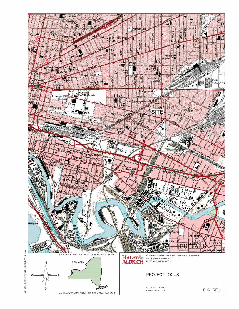
1. INTRODUCTION 1.1 Site Description The site is located at 822 Seneca Street in the City of Buffalo, Erie County, New York. The site is identified on the City of Buffalo tax maps as the parcel within section 122.27, block 1, lot 4, and is approximately 2.91 acres. The site is located on the west side of Lord Street and bound to the north by Seymour Street and the south by Seneca Street, and is approximately one mile north of the Buffalo River. A site location map is included as Figure 1. A figure showing the site boundaries is included as Figure 2. AmeriPride Services Inc. (“AmeriPride”), formerly American Linen Supply Co, owned the property from 1978 to 2014 and operated an industrial laundry facility on it from 1978 to 2004. Since 2005, the site has been unoccupied. The parcel was formerly developed with a vacant industrial building, which was demolished between 2011 and 2012 as described in Section 2 below. In January 2014, the site was sold to Mill Race Commons, LLC. 1.2 Site History According to previously prepared reports for the site, including a Phase I Environmental Site Assessment Report by C.T. Male Associates, P.C., dated December 2004, the site building was first developed in 1910. Prior to 1910, the Site is indicated to have been occupied by residential and commercial properties. Between 1910 and 1978, the Site appeared to be used as a book binding and printing facility. Coverall Service and Supply Co., (“Coverall”) a uniform cleaning facility, reportedly first occupied the Site in 1978, and the facility was used for dry cleaning operations until 1985. Available records indicate that dry-cleaning with tetrachloroethylene (PCE) was conducted at the Site between 1978 and 1985; use and/or storage of PCE were not reported after 1985. The laundry operations occupied the first floor of the site building as well as portions of the basement. Thorner Sydney Press occupied the second floor of the site building as well as portions of the basement until 1997. According to a purchase agreement dated 1977, Thorner Sydney Press’ lease agreement was initiated in 1965. In April 2004, laundering operations ceased at the site building. It was used as a laundry depot from April 2004 through spring 2005 and then as a fleet vehicle maintenance shop until July 2005. Operations moved out of the building at the end of July 2005, and the site has been vacant since. AmeriPride applied for acceptance into the New York State Department of Environmental Conservation (NYSDEC) Brownfield Cleanup Program (BCP) in January 2011 and submitted both a BCP Application and draft Remedial Investigation Work Plan (RIWP). AmeriPride was accepted into the program in March 2011 and entered into a Brownfield Cleanup Agreement (BCA) with the NYSDEC on 17 May 2011 with site identification number C915241 (refer to Appendix A). A final RIWP was submitted in May 2011 and approved by the NYSDEC on 2 June 2011 (Appendix A). Prior to entrance into the BCP, a Phase I, Phase II, supplemental Phase II and site wide groundwater sampling occurred at the site between 2004 and 2009. Those data were summarized in the RIWP dated May 2011 and used to formulate the RI program.

2
1.3 Physical Setting The site is located in an urban area of mixed industrial, commercial, and residential land use and is currently zoned for industrial use. The site is bound to the northeast by residential properties, to the southeast by vacant and commercial properties, to the southwest by vacant and commercial properties, including a BCP site, and to the northwest by residential properties. The residential property (single family home) located at 798 Seneca Street is surrounded by the site on three sides (see Figure 2). A brief summary of the geologic and hydrogeologic setting is provided below. A more detailed description is included in the Remedial Investigation/Interim Remedial Measure Report (RI/IRM) submitted under separate cover. 1.3.1 Geology
The site is generally flat, sloping slightly to the south, and is situated approximately one mile north of the Buffalo River. The overburden materials (fill and soil) encountered at the site range in thickness from approximately 14 to 23 feet thick. With the exception of in the former building basement area, which was filled with imported fill, overburden materials at the site generally consist of some combination of the following. Historic Fill: Consists of well graded gravel, sand, ash, slag, trace wood and brick, and
some clay. A distinct ash fill layer (consisting of approximately 80% ash and slag) is present beneath the former first floor building slab. The fill layer typically ranges from 0.5 to 12 feet below ground surface (bgs). Deeper fill was encountered in proximity of underground storage tanks (USTs).
Unconsolidated Clay Fill: Consists of brown or gray sandy or silty lean clay with sand and trace amounts of wood, ash and brick. This material differs from the historic fill described above in that it is primarily composed of clay with trace amounts of fill constituents.
Swamp Deposits: Swamp deposits containing organic materials were identified in a small area in the center of the former building slab area ranging from approximately 5 to 9 feet bgs prior to the soil removal IRM and 0.4 to 4.6 feet bgs post soil removal IRM1.
Glaciolacustrine Deposits: Consist of native soil deposits of brown and gray clay with sand and silt. This layer ranges in depth from approximately 1 to 21 feet bgs.
Glacial Till: Consists of clayey and silty sands. This layer ranges in depth from
approximately 14 to 23 feet bgs.
The surface of bedrock or drilling refusal was encountered between 14 and 23 feet bgs (El. 563 to El. 572). The site is situated in the Central Lowlands Physiographic Province, characterized by nearly flat-lying rocks of Devonian, Silurian and Ordovician Age. Bedrock underlying the site is mapped as middle Devonian Onondaga Limestone.
1 Ground surface was lowered in the former slab on grade area as a result of the soil removal IRM.

3
1.3.2 Hydrogeology
In January 2013, groundwater was encountered between 2.75 and 10.5 feet bgs. Groundwater elevation data suggest that groundwater flows toward the south with approximate hydraulic gradient of between 0.01 and 0.08 feet per foot (ft/ft) (Figure 3). This southward flow direction is consistent with the expectation that groundwater may be locally controlled by the Buffalo River, which is located less than one mile south of the site. Hydraulic conductivity was not measured as part of this RI, however hydraulic conductivities in lacustrine silts and clays in North America range between 1x10⁻⁴ and 1x10⁻⁸ m/day2.
1.4 Applicable Comparison Criteria Samples collected as part of the RI and IRM work were analyzed at Pace Analytical Services in Pittsburgh, Pennsylvania and Schenectady, New York (Pace) and analytical results were compared to the following criteria based on media analyzed: Soil:
Soil investigation data are compared to the NYSDEC Soil Cleanup Objectives restricted for the protection of groundwater (protection of groundwater SCOs), commercial use (commercial SCOs), and industrial use (industrial SCOs) contained in the December 2006 NYCRR Part 375 and October 2010 NYSDEC Commissioners Policy 51 (CP-51). Imported fill data are compared to the Imported Fill Requirements contained in the May 2010 NYSDEC Technical Guidance for Site Investigation and Remediation (DER-10).
Groundwater: Groundwater data are compared to the June 1998 NYSDEC Division of Water Technical and Operational Guidance Series 1.1.1 Ambient Water Quality Standards and Guidance Values, Class GA for the protection of a source of drinking water modified per the April 2000 addendum (TOGS 1.1.1).
Soil Vapor: Currently there are no applicable criteria for comparison of soil vapor concentrations in New York. Soil vapor data was evaluated in consideration of the October 2006 New York State Department of Health (NYSDOH) Final Guidance for Evaluating Soil Vapor Intrusion in the State of New York (NYSDOH VI Guidance).
Soil Vapor Intrusion Samples (Indoor Air/Sub-Slab Vapor): Soil vapor intrusion (SVI) analytical results were compared to Matrix 1 and Matrix 2 of the NYSDOH VI Guidance.
2 D.A. Stephenson, et. al, 1988
4
2. REMEDIAL INVESTIGATION SUMMARY A brief summary of the RI and IRM activities as well as a summary of the exposure assessment conducted as part of RI activities follows below. RI and IRM activities were conducted according to the NYSDEC-approved 31 May 2011 Remedial Investigation Work Plan, 5 July 2012 Revised Interim Remedial Measure Work Plan and the 18 September 2013 Revised Interim Remedial Measure Work Plan. Refer to the RI/IRM Report for a more detailed account of those activities. Figures summarizing site conditions as described below are included as Figures 4 through 9. 2.1 Summary of RI Activities Activities conducted during the RI included demolition of the building and remedial subsurface investigations. Initial RI activities were conducted at the site between November 2011 and December 2012. Following the soil removal IRM (discussed below), supplemental RI activities were conducted in December 2013 to complete the Conceptual Site Model (CSM). Demolition activities included: Asbestos abatement and hazardous building material removal Removal of the above-grade building structure Removal of the first floor building slab Basement dewatering and clean out Removal of the basement walls to the extent required to meet city code requirements, floor
slab, and associated drainage structures Removal of the aboveground storage tanks and building equipment Removal of transformer pads and bollards Backfill of the former basement Subsurface investigation activities included: Basement sub-slab soil investigation Test pitting in the former parking lot area, near the former underground storage tanks, and in
the first floor slab/former dry cleaning area. Soil boring and discrete groundwater investigation in the former dry cleaning area. Installation of permanent overburden and bedrock monitoring wells Site-wide groundwater sampling Offsite soil and groundwater sampling Soil vapor investigation Post-IRM surface soil confirmation and fill characterization sampling beneath the former
basement slab In addition to the activities listed above, a soil vapor intrusion investigation was conducted at 798 Seneca Street adjacent to the west side of the site. This adjacent property was considered a potential receptor for soil vapor intrusion from dry cleaning related compounds present in soil, groundwater, and soil vapor.
5
2.2 Summary of Interim Remedial Measure Activities
Two interim remedial measures (IRMs) were conducted concurrently with the RI activities. The first IRM was conducted to address oily material encountered beneath the basement floor
slab between two former cisterns located in the southwest corner of the basement. The IRM was conducted in accordance with a NYSDEC approved Revised IRM Work Plan dated July 2012. This IRM was completed in 2012 when the oily material was excavated.
The second IRM was conducted to remove historic fill materials present in the former building slab area to bring the site to level grade per the City of Buffalo demolition code, remove a former waste oil UST, and to excavate areas of shallow soil impacted by target dry cleaning related compounds with concentrations above the protection of groundwater SCOs. The IRM was conducted in accordance with a NYSDEC approved Revised IRM Work Plan dated 18 September 2013. The historic fill materials and the UST removal were completed, and a substantial amount of shallow soil impacts were removed during 2013, but shallow soil impacts remain in some areas of the former slab-on-grade area.
2.3 Summary of Conceptual Site Model The results of the RI were used to develop the Conceptual Site Model (CSM) as follows. Overall, contaminants of concern (COCs) were detected at concentrations onsite in fill and native soil above commercial and protection of groundwater SCOs and in groundwater at concentrations exceeding groundwater standards and guidance criteria. A summary of soil, groundwater, and soil vapor conditions following completion of the IRM activities is provided below. 2.3.1 Soil Conditions
COCs were identified based on the multiple detection of any one of a broad suite of organic and inorganic substances that are related to the former site operations and are present at concentrations higher than the relevant standards, criteria, and guidelines (SCGs). The SCGs for the site include the Part 375 Restricted Use Soil Cleanup Objectives (SCOs) for protection of groundwater, commercial use, and industrial use; and the NYS Ambient Water Quality Standards and Guidance Values (class GA) specified in NYSDEC TOGS 1.1.1 for groundwater. The COCs identified for the site include: Target chlorinated volatile organic compounds (CVOCs): tetrachloroethene (PCE),
trichloroethene (TCE), cis-1,2-dichloroethene (cis-1,2-DCE), trans-1,2-dichloroethene (trans-1,2-DCE), and vinyl chloride in soil.
Polycyclic aromatic hydrocarbons (PAHs) and heavy metals (arsenic, copper, lead, and
mercury) in historic fill. Prior to soil removal IRM activities, target CVOCs were detected at concentrations exceeding applicable criteria in shallow fill near the former waste oil underground storage tank (UST), and on the southern side of the first floor slab near the former dry cleaning operations proximate to TP-16 and TP-18. Target CVOCs were also identified in deep native soil, likely as a result of impacted groundwater at depth rather than from a source within the soil at or above the sample location.

6
During the soil removal IRM, the areas of shallow fill impacts (TP-16, TP-18, and the UST) were removed along with 1 to 4.5 feet of soils and historic fill in the former slab-on-grade area. Following IRM activities, confirmation sampling from the ground surface of the slab-on-grade area indicated that soils at the surface and above the water table continue to be impacted with residual target CVOCs (PCE, TCE, and cis-1,2-DCE) on the southwestern portion of the former slab-on-grade area, in what was the former dry cleaning area. Concentrations of total target CVOCs detected in that area ranges from non-detect up to approximately 16 mg/kg, with the exception of one sample location on the southern side of the site, which contained concentrations of total target CVOCs at 302.9 mg/kg (Figure 9). The PAHs and metals were identified sporadically within historic fill located throughout the top 5 to 12 feet of the overburden in the former parking lot and first floor slab areas. It is anticipated that those constituents are inherent to the fill itself, which is historic fill and not contaminated as a result of historical building operations (Figure 5). Limited remediation including removal of solid media containing target CVOCs that that have the potential to impact groundwater and placement of a soil cover to restrict contact to historic fill materials are recommended future remedial actions. 2.3.2 Groundwater Conditions
Target CVOCs were also identified in groundwater at concentrations exceeding groundwater standards in two locations on the southern side of the site in and proximate to the former dry cleaning area. Groundwater was encountered from approximately 2.75 and 10.5 feet below ground surface and appears to be flowing in a southerly direction (Figure 3). The highest current total onsite target CVOC concentration is approximately 140 ug/L, which was detected in MW-3 (Figure 4). The groundwater table is present in dense lacustrine and glacial till overburden soils with low hydraulic conductivities. Target CVOC concentrations detected offsite have been very close to or below the groundwater standards, and are indicative of natural attenuation, and the downgradient edge of groundwater impacts. COCs in offsite groundwater are attenuating naturally and therefore groundwater remediation does not appear to be warranted.
2.3.3 Soil Vapor Conditions
COCs were detected in soil vapor, proximate to the residence at 798 Seneca Street. Target CVOCs and petroleum-related VOCs were detected in two soil vapor samples. However, based on the low detections of those compounds in soil and groundwater proximate to the soil vapor sample collection points, it does not appear that soil or groundwater are acting as a source of those vapor concentrations. It is possible that vapor has accumulated over time below the pavement. A soil vapor intrusion investigation was conducted in December 2013 in the basement of 798 Seneca Street. The scope was approved by the NYSDEC and NYSDOH on 4 December 2013. The results identified low levels of PCE in the sub-slab vapor, indoor air, and outdoor air and low levels of TCE in the sub-slab vapor and outdoor air. When compared against Matrix 1 and Matrix 2 of the NYSDOH VI Guidance, no further action is recommended or required.
7
2.4 Summary of Exposure Assessment Currently, there is no complete exposure pathways identified on site because the site is surrounded by a permanent chain-link fence, the groundwater is not currently used nor is groundwater use planned in the future, and there are no buildings onsite to present a potential for vapor intrusion. However, a long-term potential exposure pathway to COCs in soil will remain and site management and engineering controls are warranted.

8
3. REMEDIAL GOALS AND REMEDIAL ACTION OBJECTIVES 3.1 Remedial Goal The remedial project goal is to eliminate or mitigate, to the extent feasible, significant threats to public health and the environment through the proper application of scientific and engineering principles, given the intended use of the site, which is anticipated to be for commercial or industrial purposes. Currently, development is not planned at this time. Specifically, the remedial action goals include to: Prevent contact and ingestion of contaminated soil and groundwater. Remove the source of groundwater contamination. Prevent migration of contaminants via groundwater. 3.2 Remedial Action Objectives The objectives of the remedy are specifically to: Conduct source removal of shallow soils impacted with target CVOCs identified in the former
dry cleaning/building slab on grade area present at concentrations that could further impact groundwater as a result of infiltration of surface water in the future.
Eliminate or reduce potential human exposure to historic fill impacted with PAHs and metals above commercial use SCOs to protect public health and the environment and facilitate future redevelopment of the site.
9
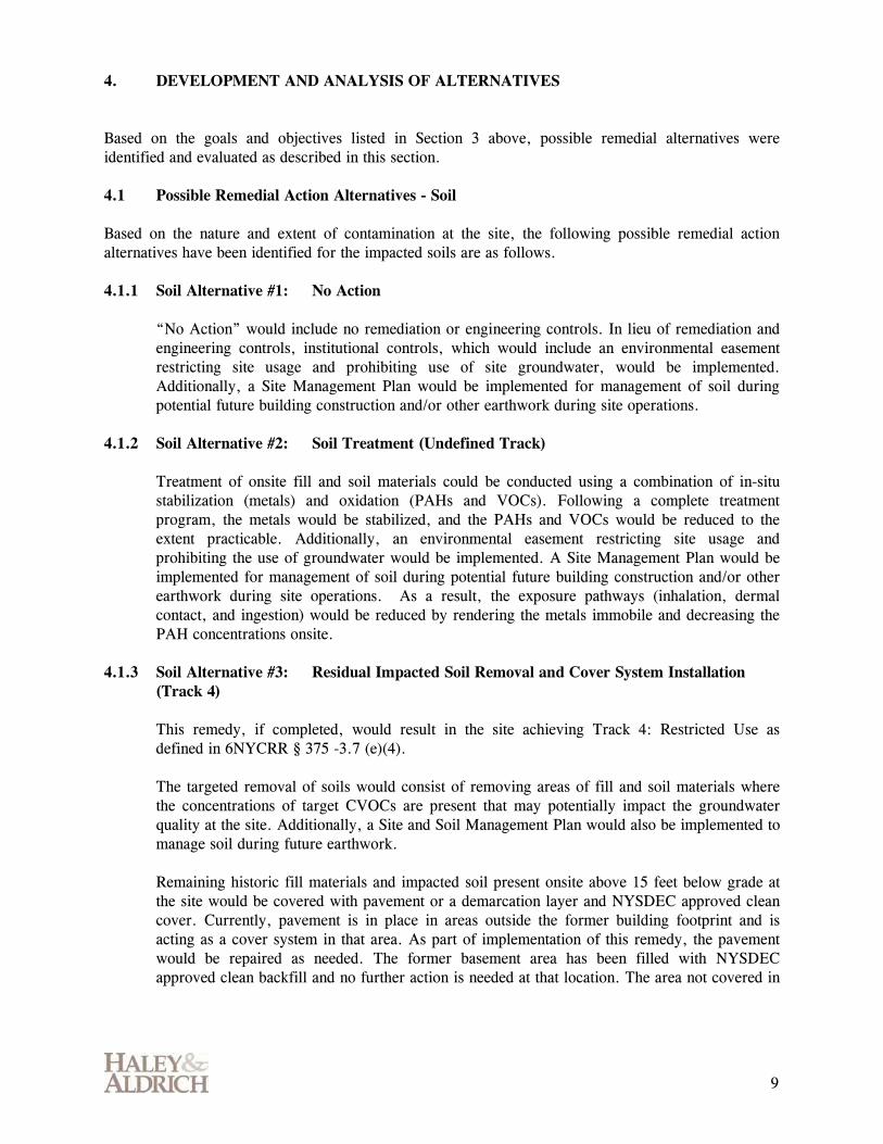
4. DEVELOPMENT AND ANALYSIS OF ALTERNATIVES Based on the goals and objectives listed in Section 3 above, possible remedial alternatives were identified and evaluated as described in this section. 4.1 Possible Remedial Action Alternatives - Soil Based on the nature and extent of contamination at the site, the following possible remedial action alternatives have been identified for the impacted soils are as follows. 4.1.1 Soil Alternative #1: No Action
“No Action” would include no remediation or engineering controls. In lieu of remediation and engineering controls, institutional controls, which would include an environmental easement restricting site usage and prohibiting use of site groundwater, would be implemented. Additionally, a Site Management Plan would be implemented for management of soil during potential future building construction and/or other earthwork during site operations.
4.1.2 Soil Alternative #2: Soil Treatment (Undefined Track)
Treatment of onsite fill and soil materials could be conducted using a combination of in-situ stabilization (metals) and oxidation (PAHs and VOCs). Following a complete treatment program, the metals would be stabilized, and the PAHs and VOCs would be reduced to the extent practicable. Additionally, an environmental easement restricting site usage and prohibiting the use of groundwater would be implemented. A Site Management Plan would be implemented for management of soil during potential future building construction and/or other earthwork during site operations. As a result, the exposure pathways (inhalation, dermal contact, and ingestion) would be reduced by rendering the metals immobile and decreasing the PAH concentrations onsite.
4.1.3 Soil Alternative #3: Residual Impacted Soil Removal and Cover System Installation (Track 4)
This remedy, if completed, would result in the site achieving Track 4: Restricted Use as defined in 6NYCRR § 375 -3.7 (e)(4). The targeted removal of soils would consist of removing areas of fill and soil materials where the concentrations of target CVOCs are present that may potentially impact the groundwater quality at the site. Additionally, a Site and Soil Management Plan would also be implemented to manage soil during future earthwork. Remaining historic fill materials and impacted soil present onsite above 15 feet below grade at the site would be covered with pavement or a demarcation layer and NYSDEC approved clean cover. Currently, pavement is in place in areas outside the former building footprint and is acting as a cover system in that area. As part of implementation of this remedy, the pavement would be repaired as needed. The former basement area has been filled with NYSDEC approved clean backfill and no further action is needed at that location. The area not covered in

10
pavement or associated with the former basement would be covered with a demarcation layer and at least one foot of NYSDEC approved clean backfill.
4.1.4 Soil Alternative #4: Removal and offsite disposition of impacted soil/fill (Track 1/Track 2)
The complete removal remedy would involve the excavation, characterization, and offsite disposition of all fill materials and soils impacted by COCs above applicable risk based SCOs 15 feet below ground surface to achieve Track 2 or to bedrock to achieve Track 1. The excavations will be backfilled using NYSDEC approved clean cover material. This remedy would achieve soil remedial Track 1 or 2 with respect to soil impacts per 6NYCRR § 375 -3.7 (e)(2). This alternative represents the least restrictive remedial option that is practicable for the site.
4.2 Possible Remedial Action Alternatives – Groundwater Based on the nature and extent of contamination at the site, the following potential remedial action alternatives have been identified for the impacted soils are identified as follows. 4.2.1 Groundwater Alternative #1: Groundwater Monitoring
This alternative would involve developing a program to monitor VOC trends and potential migration at the existing monitoring well locations on and offsite. The wells will be sampled routinely and analyzed for VOCs per an approved Site Management Plan. For the purposes of cost estimating, it is assumed that this remedial action would be conducted for a 30-year duration to allow consistency for evaluation purposes. This time frame for cost estimation is based on the EPA’s 1998 Guidance for Conducting Remedial Investigations and Feasibility Studies under CERCLA. Note that the 30 year time frame was used for consistency for cost estimating only, and is not an estimation of the anticipated length of the monitoring program alternative. Groundwater quality should improve over time as a result of residual source removal, and natural attenuation.
4.2.2 Groundwater Alternative #2: In-situ (Substrate Injection) Treatment
In-situ groundwater remediation processes include bioremediation and chemical oxidation, each of which rely on the distribution of an amendment. Typically, bioremediation would consist of injection of an organic carbon substrate into groundwater to enhance the natural breakdown of organic contaminants including dry cleaning solvents. Substrates include but are not limited to lactate, emulsified vegetable oil, polyacetate/acetate esters, chitin, and cheese whey. The in-situ treatment process would involve injection of the substrate either directly using direct push methods or via injection wells in focused areas onsite. Following injection, a groundwater monitoring program will be implemented per a Site Management Plan to evaluate remedial progress. Additional injections may be needed once the substrate is consumed to maintain the enhanced benefit. Chemical oxidation would consist of injection of a chemical oxidant such as sodium or potassium permanganate, activated persulfate, or Fenton’s reagent into groundwater to eliminate organic contaminants.

11
In order to evaluate the appropriate substrate, feasibility of the alternative, and scope and design of the injection, a pilot test would need to be conducted prior to full-scale remedy implementation.
4.2.3 Groundwater Alternative #3: Ex-Situ (Pumping and Treatment) and Migration Control Ex-situ treatment is a process that controls the migration of COCs through the pumping of large volumes of groundwater (via multiple extraction points) and treating the extracted groundwater. Ex-situ treatment would involve installation of pumping wells and a treatment system that would be housed onsite in a specially constructed space (e.g. outbuilding or dedicated room inside a future development). The benefits of this treatment option could include hydraulic control of groundwater. At this time while low concentrations of vinyl chloride have been detected immediately offsite, substantial evidence of offsite contaminant migration has not been identified. Ex-situ treatment does not aid in the destruction of CVOCs in the groundwater. Ex-situ treatment processes require routine and continued maintenance of treatment system components. This includes replacing and/or disposing of parts filters, and treatment media (e.g. carbon). In addition, a groundwater monitoring program will be implemented per a Site Management Plan and remedial progress would be continually evaluated. Due to the geologic conditions at the site, pumping and treatment would need to be evaluated via a pumping test to assess feasibility of the technology and to facilitate proper design of the system. Given the soil conditions (i.e. fine grained silts and glacial tills), it is not anticipated that an ex-situ treatment system would result in effective groundwater recovery at this site.
4.3 Consideration for Future Soil Vapor Intrusion Currently there are no structures onsite; therefore there is an incomplete exposure pathway for VOC impacted soil vapor and remedial alternatives are not considered in this analysis. Because of the impacts to groundwater, provisions will be included in the Site Management Plan to address the potential for soil vapor intrusion in structures planned for future development. Measures to address the potential for soil vapor intrusion will include analytical testing and installation of engineering controls (e.g. vapor barriers, sub-slab depressurization systems, etc.).
4.4 Evaluation of Alternatives Per the May 2010 NYSDEC DER-10 guidance and the 6NYCRR Part 375 § 1.8 (f), eight criteria are used to evaluate how the proposed remedy would be protective of public health and the environment: 1. Overall Protection of Human Health and the Environment 2. Compliance with Standards, Criteria and Guidance (SCGs) 3. Long-Term Effectiveness and Permanence 4. Reduction of Toxicity, Mobility or Volume 5. Short-Term Effectiveness 6. Implementability 7. Cost 8. Land Use DER-10 and Part 375 includes “community acceptance” as a ninth criterion; however this criterion is considered after the public review process of this Alternatives Analysis and as part of the final

12
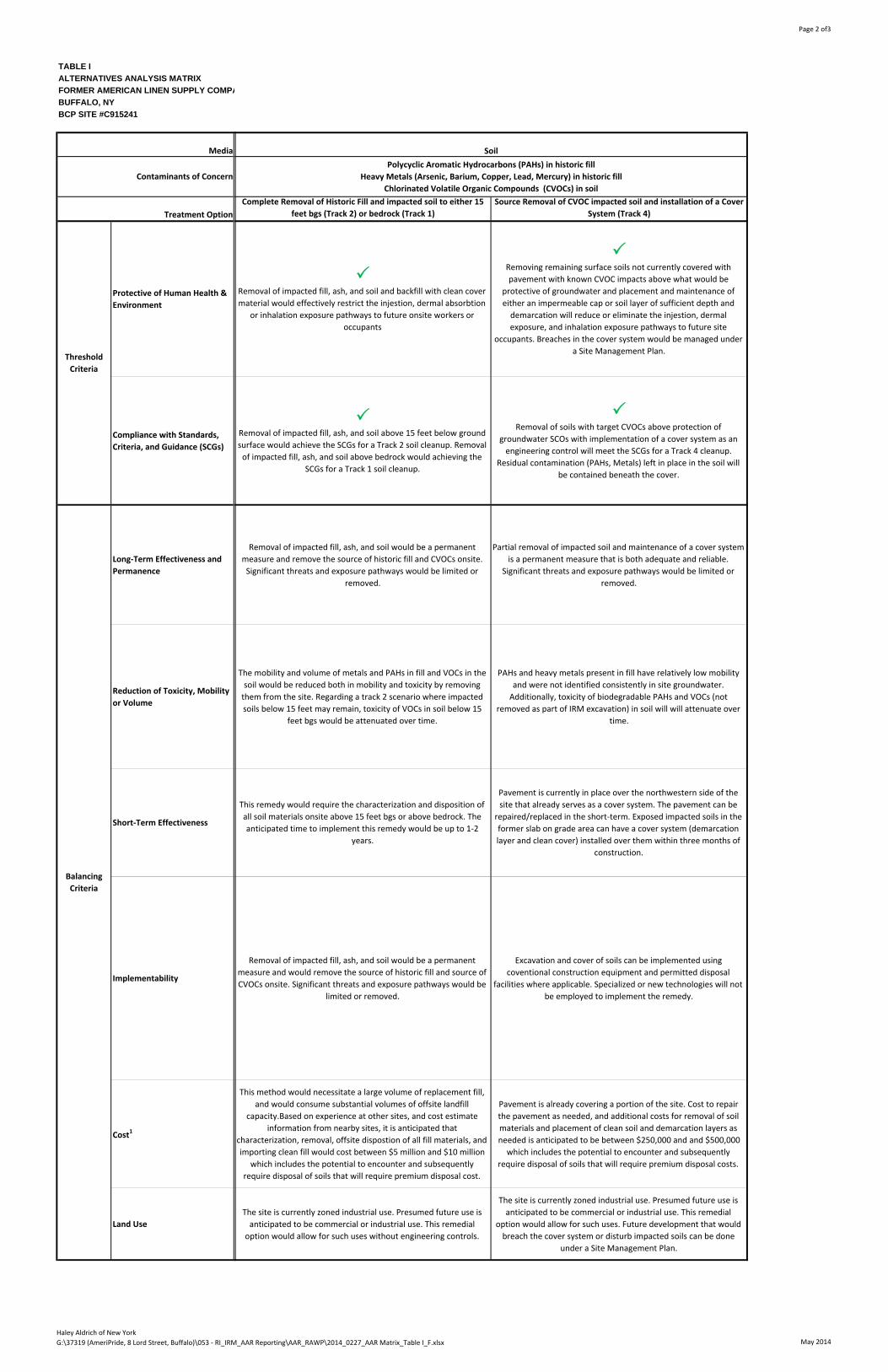
NYSDEC approval of the remedy of the site. Therefore, this criterion has not been evaluated as part of this AAR. Per DER-10, the first two criteria are considered threshold criteria and must be satisfied in order for an alternative to be considered for selection. The following six are balancing criteria, which are used to compare the positive and negative aspects of each of the remedial alternatives, provided the alternative satisfies the threshold criteria. Those that do not satisfy the threshold criteria are rejected and not further evaluated. Table I includes a matrix of the alternatives described in sections 4.1 and 4.2 above evaluated against the eight criteria. 4.4.1 Evaluation of Threshold Criteria
As shown in Table I, the four soil remedial alternatives and three groundwater remedial alternatives were evaluated against the two threshold criteria (Overall Protection of Human Health and the Environment and Compliance with SCGs). Two out of the four soil alternatives did not meet those criteria and were therefore rejected. All remaining alternatives satisfied those criteria. The rejected alternatives included: Soil Alternative #1: No Action Soil Alternative #2: Soil Treatment Specific rationale is described in Table I. In summary, the two alternatives above were not protective of human health and the environment and/or they did not achieve compliance with the SCGs.
4.4.2 Evaluation of Balancing Criteria
The remaining two soil remedial alternatives and three groundwater remedial alternatives that met the threshold criteria were evaluated against the balancing criteria as shown in Table I. The results of the evaluation are summarized below: Soil Alternatives
The two remaining alternatives include (a) excavation of all impacted fill materials and soils up
to 15 feet below grade (Track 2) or bedrock (Track 1) (primarily the soils remaining in the former parking lot area) and (b) confining those materials below a cover system (Track 4). Both alternatives would allow for redevelopment of the site for commercial and/or industrial use.
Soil Alternative #4 allows more flexibility for future development without premium
construction and ongoing maintenance costs; however the costs to implement the removal remedy is significantly higher (several orders of magnitude) than the costs to maintain a cover system. The removal option is also considered less sustainable particularly in the absence of a defined development plan given the need to relocate soil to a landfill and added need for hauling equipment. Furthermore, time to implement the removal remedy would be up to 1-2 years due to the need to characterize the material for landfill acceptance. Groundwater Alternatives

13
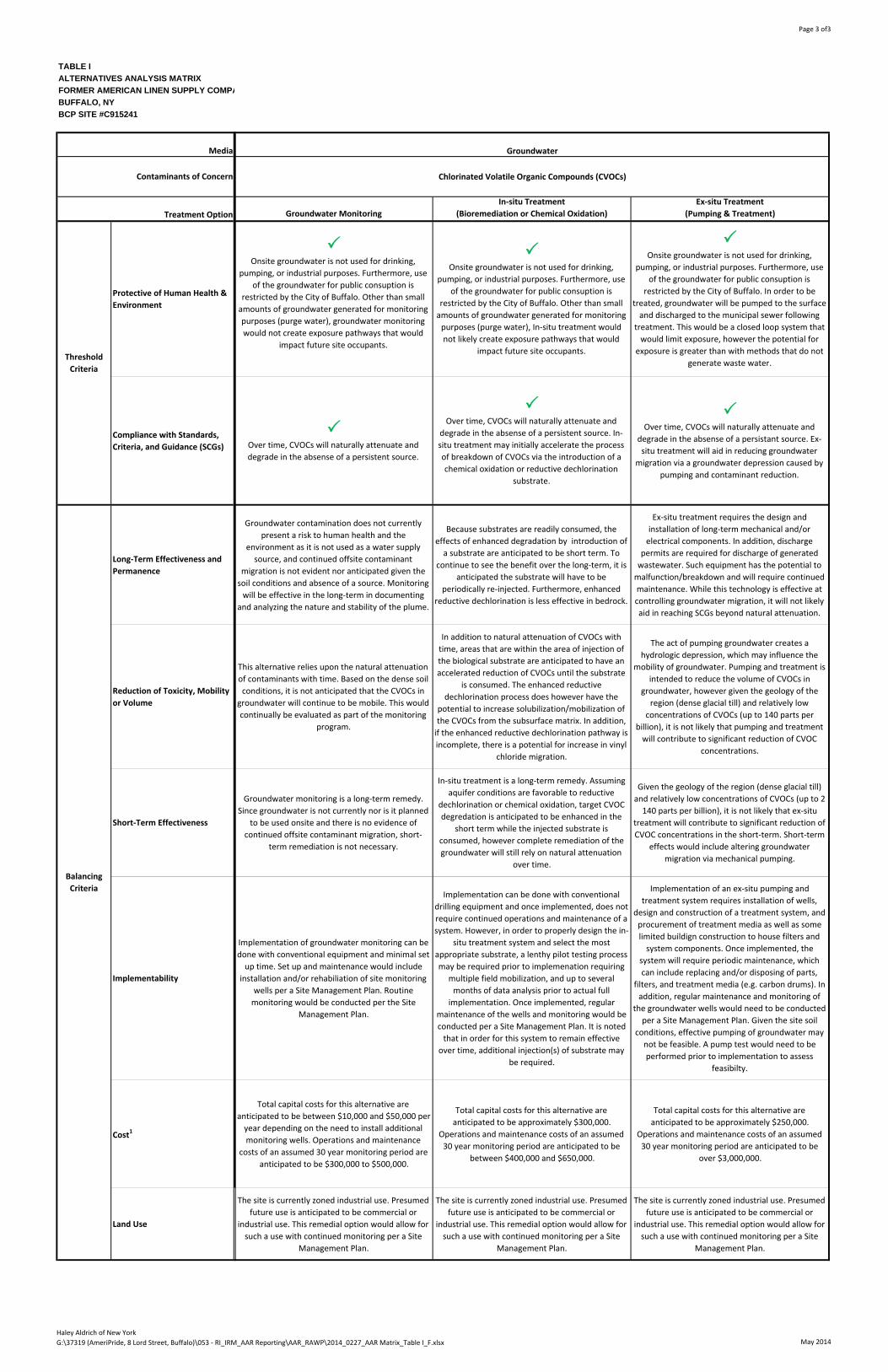
All three alternatives involve ongoing monitoring of groundwater. Currently, highest total groundwater concentration of dry cleaning solvent and breakdown compounds is 140 ug/L in MW-3, and it is anticipated that over time those compounds will naturally degrade in the absence of a persistent source of contamination. A specific residual source area (e.g. presence of dense non-aqueous phase liquid (DNAPL) or high concentration of VOCs in saturated soil) contributing to the groundwater contamination has not been identified. The in-situ treatment option and pumping and treatment option aim to actively reduce contamination by introducing a substrate to enhance natural breakdown or oxidize contaminants, or by adding a migration control element, respectively. Each alternative is further evaluated below and in Table I. In-situ Treatment In-situ treatment has the potential added benefit of initially degrading the contaminants in the overburden groundwater more rapidly in areas where treatment substrates are delivered. It is anticipated that more than one injection of the treatment may be required to maintain the more rapid remediation pace. Preparation in the form of a pilot test to appropriately design the treatment program and potential installation of addition wells (e.g. injection wells) would be required prior to full implementation. Costs to implement the in-situ treatment program are significantly higher than groundwater monitoring alone. In addition, due to the dense glacial till present at the site, distribution of the substrate within the aquifer may not be feasible. Ex-situ Treatment (Pumping and Treatment) Pumping and treatment has the potential added benefit of groundwater migration control; however given the geology of the region and relatively low concentrations of dry cleaning solvents in the water, it is not needed, nor is it anticipated that it would contribute to reducing the volume of target CVOCs in groundwater given the site soil conditions (fine grained silts and glacial tills) which restrict groundwater flow. Furthermore, evidence of continued offsite migration of target CVOCs has not been identified in the data collected to date. Because pumping and treatment includes mechanical systems and removal of groundwater, it would require a high amount of short-term capital to design and install the system, procure discharge permits, etc. and additional capital over the long term for ongoing maintenance and operation of the system. Total capital costs are likely to be over an order of magnitude higher than groundwater monitoring alone. In addition, by removing impacted groundwater from the subsurface for treating, a potential worker exposure pathway is created. Groundwater Monitoring Groundwater monitoring alone does not provide any means to expedite remediation. However, given the relatively low concentrations detected in groundwater onsite, the limited evidence of substantial offsite migration of contaminants in groundwater, the current soil conditions limiting groundwater flow due to low hydraulic conductivity, and prohibition of use of the groundwater on the site or surrounding area, this option does present the most cost effective approach for addressing the groundwater conditions in the short and long-term provided continued monitoring indicates that the current groundwater conditions are remaining unchanged or improving. Groundwater quality should improve over time as a result of residual source removal and natural attenuation.
14
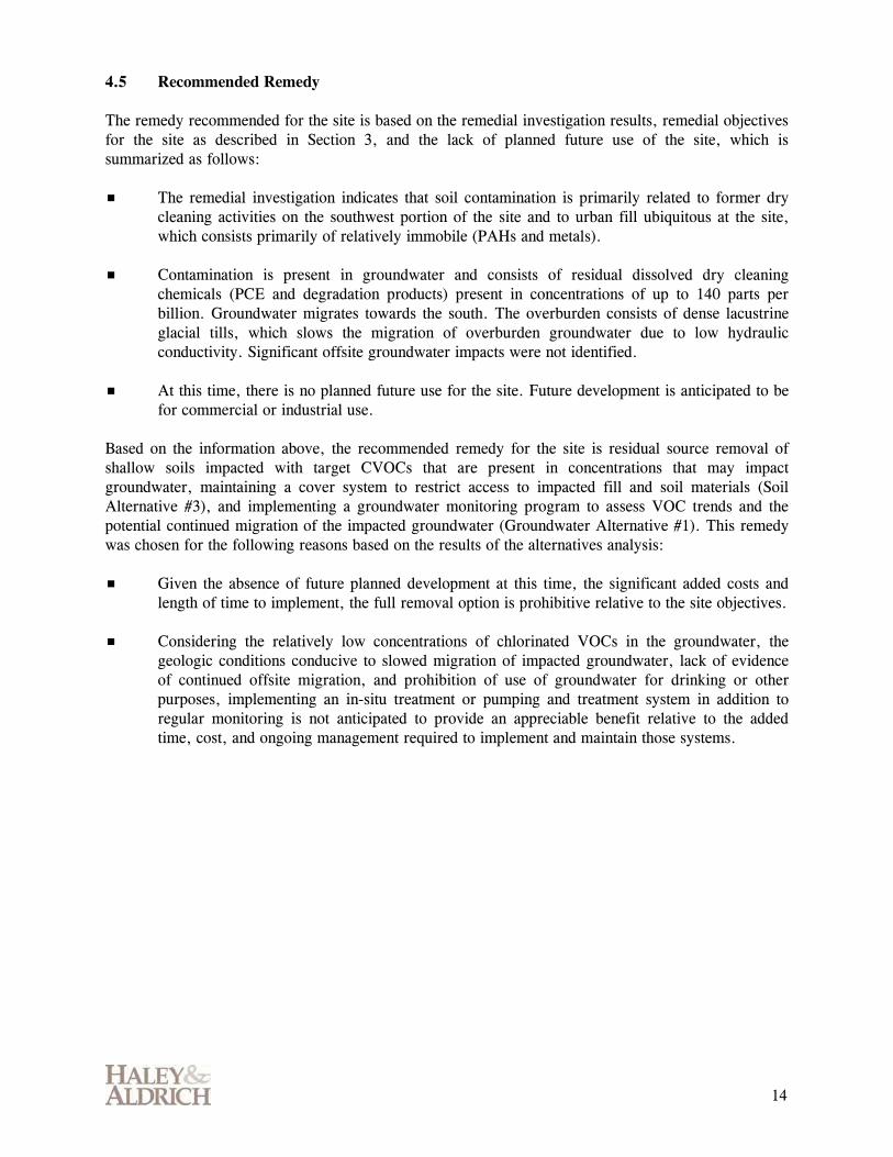
4.5 Recommended Remedy The remedy recommended for the site is based on the remedial investigation results, remedial objectives for the site as described in Section 3, and the lack of planned future use of the site, which is summarized as follows: The remedial investigation indicates that soil contamination is primarily related to former dry
cleaning activities on the southwest portion of the site and to urban fill ubiquitous at the site, which consists primarily of relatively immobile (PAHs and metals).
Contamination is present in groundwater and consists of residual dissolved dry cleaning chemicals (PCE and degradation products) present in concentrations of up to 140 parts per billion. Groundwater migrates towards the south. The overburden consists of dense lacustrine glacial tills, which slows the migration of overburden groundwater due to low hydraulic conductivity. Significant offsite groundwater impacts were not identified.
At this time, there is no planned future use for the site. Future development is anticipated to be for commercial or industrial use.
Based on the information above, the recommended remedy for the site is residual source removal of shallow soils impacted with target CVOCs that are present in concentrations that may impact groundwater, maintaining a cover system to restrict access to impacted fill and soil materials (Soil Alternative #3), and implementing a groundwater monitoring program to assess VOC trends and the potential continued migration of the impacted groundwater (Groundwater Alternative #1). This remedy was chosen for the following reasons based on the results of the alternatives analysis: Given the absence of future planned development at this time, the significant added costs and
length of time to implement, the full removal option is prohibitive relative to the site objectives.
Considering the relatively low concentrations of chlorinated VOCs in the groundwater, the geologic conditions conducive to slowed migration of impacted groundwater, lack of evidence of continued offsite migration, and prohibition of use of groundwater for drinking or other purposes, implementing an in-situ treatment or pumping and treatment system in addition to regular monitoring is not anticipated to provide an appreciable benefit relative to the added time, cost, and ongoing management required to implement and maintain those systems.
15
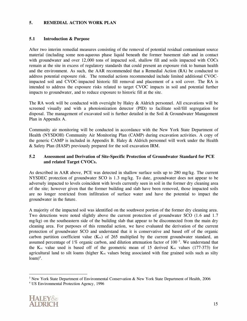
5. REMEDIAL ACTION WORK PLAN 5.1 Introduction & Purpose After two interim remedial measures consisting of the removal of potential residual contaminant source material (including some non-aqueous phase liquid beneath the former basement slab and in contact with groundwater and over 12,000 tons of impacted soil, shallow fill and soils impacted with COCs remain at the site in excess of regulatory standards that could present an exposure risk to human health and the environment. As such, the AAR recommended that a Remedial Action (RA) be conducted to address potential exposure risk. The remedial actions recommended include limited additional CVOC-impacted soil and CVOC-impacted historic fill removal and placement of a soil cover. The RA is intended to address the exposure risks related to target CVOC impacts in soil and potential further impacts to groundwater, and to reduce exposure to historic fill at the site. The RA work will be conducted with oversight by Haley & Aldrich personnel. All excavations will be screened visually and with a photoionization detector (PID) to facilitate soil/fill segregation for disposal. The management of excavated soil is further detailed in the Soil & Groundwater Management Plan in Appendix A. Community air monitoring will be conducted in accordance with the New York State Department of Health (NYSDOH) Community Air Monitoring Plan (CAMP) during excavation activities. A copy of the generic CAMP is included in Appendix B. Haley & Aldrich personnel will work under the Health & Safety Plan (HASP) previously prepared for the soil excavation IRM. 5.2 Assessment and Derivation of Site-Specific Protection of Groundwater Standard for PCE
and related Target CVOCs. As described in AAR above, PCE was detected in shallow surface soils up to 280 mg/kg. The current NYSDEC protection of groundwater SCO is 1.3 mg/kg. To date, groundwater does not appear to be adversely impacted to levels coincident with levels currently seen in soil in the former dry cleaning area of the site; however given that the former building and slab have been removed, those impacted soils are no longer restricted from infiltration of surface water and have the potential to impact the groundwater in the future. A majority of the impacted soil was identified on the southwest portion of the former dry cleaning area. Two detections were noted slightly above the current protection of groundwater SCO (1.6 and 1.7 mg/kg) on the southeastern side of the building slab that appear to be disconnected from the main dry cleaning area. For purposes of this remedial action, we have evaluated the derivation of the current protection of groundwater SCO and understand that it is conservative and based off of the organic carbon partition coefficient value (Koc) of 265 multiplied by the current groundwater standard, an assumed percentage of 1% organic carbon, and dilution attenuation factor of 100 3. We understand that the Koc value used is based off of the geometric mean of 15 derived Koc values (177-373) for agricultural land to silt loams (higher Koc values being associated with fine grained soils such as silty loam)4.
3 New York State Department of Environmental Conservation & New York State Department of Health, 2006 4 US Environmental Protection Agency, 1996

16
Given that the soils at the site consist of fine grain glacial till material, it is justifiable to utilize a Koc value for a more similar soil type rather than a geometric mean of non-applicable soil type Koc values. As such, we have developed a site-specific cleanup goal of 1.8 mg/kg for PCE, which utilizes the highest derived Koc value (373) provided in the EPA sources referenced in their 1996 Soil Screening Guidance; Technical Document. Using this same analysis and reference sources, the protection of groundwater SCO for TCE has been recalculated to 0.75 mg/kg. The technical documents reviewed did not include multiple Koc values for cis-1,2-DCE or vinyl chloride, therefore the current NYSDEC protection of groundwater SCO is used for those two target CVOCs as a default. Figure 9 provides a schematic of soil grids that will be excavated as part of the remedial action based on a modified site-specific protection of groundwater standard of 1.8 mg/kg for PCE and 0.75 mg/kg for TCE. 5.3 Site Preparation The necessary permits from the City of Buffalo and others, as necessary, will be obtained prior to the start of the remedial action.
5.4 Removal of Shallow Fill Soils Impacted with Chlorinated Volatile Organic Compounds Based on post IRM confirmation surface sampling, an area of fill and soil in the former dry cleaning area was identified to be impacted with PCE, TCE, and/or cis-1,2-DCE above site-specific protection of groundwater SCOs as shown on Figure 9. Depth of the impacted area is unknown. This area will be incrementally sampled and excavated as described below. Based on the confirmation sample results to date, no additional sampling or excavation is planned for the northern portion of the slab-on-grade area as concentrations of target CVOCs above site-specific protection of groundwater SCOs were not detected. 5.4.1 Soil Excavation Procedure
The former dry cleaning excavation area will be divided into sections and the soil will be excavated from the impacted area shown on Figure 9 in approximately 6 inch-depth increments to the extent practicable. Excavated soil/fill will be segregated in piles comprising soil from their respective section and stockpiled in approximately 100 ton piles for characterization and disposal per the Soil and Groundwater Management Plan in Appendix A. The excavation will continue in approximately 6 inch increments until the following occurs: Vertically: Confirmation samples indicate that no further excavation is necessary (refer to
Section 5.4.2 below); bedrock is encountered; or the practical limits of the excavation have been reached (i.e., maintaining a safe excavation without the use of shoring or without excessive management of groundwater infiltration or the edge of the property line has been reached).
Laterally: The lateral limits of the excavation are shown on Figure 9 and are as follows:
North: The surveyed limit of the impacted soils determined based on post-soil removal IRM confirmation sampling.

17
South: The property line and surveyed limits of impacted area base on post-soil removal IRM confirmation sampling. East: The surveyed limit of the impacted area determined based on post-soil removal IRM confirmation sampling. West: The limits of the slab-on-grade area, previously excavated test pits and the surveyed limit of impacted soils determined based on post-IRM confirmation sampling.
Once the excavation is deemed complete, the excavation will be backfilled and covered as described in Section 5.5 below pending NYSDEC approval.
5.4.2 Confirmation Sampling
After each 6 inch layer of soil is removed from the former dry cleaning area, one set of discrete surface samples will be collected in the center of every 900 square foot (sf) grid or as directed by the NYSDEC field representative. The samples will be analyzed at an ELAP Certified laboratory for target CVOCs (PCE, TCE, cis-1,2-DCE, and vinyl chloride) VOCs via EPA Method 8260.
Excavation will continue within the 900 sf grid based on those results. Following excavation, additional confirmation samples will be collected as described above. The process continues until the excavation is deemed complete per analytical testing. In the case of Grid 37, in which PCE was detected in the surface (0 to 6-inch interval) at 280 mg/kg during the Post-Soil Removal IRM confirmation sampling, subsurface samples will be collected from 12 and 24 inches prior to excavation to inform the required excavation depth. If excavation is required to go deeper than 24 inches, excavation will continue in 6-inch layers in accordance with the standard process for excavation and confirmation sampling described above.
5.5 Placement of Cover System Once excavation activities are completed, a cover system will be placed over the site based on the area designation as described below and shown on Figure 10. The cover system is intended to serve as an engineering control for the site in accordance with a Track 4 cleanup scenario per 6 NYCRR Part 375. The cover system will consist of the following: 5.5.1 Impermeable Cover
The pavement and UST areas located on the western side of the site and not formerly covered by the building footprint will have pavement and existing concrete serve as the cover system. Existing pavement will be repaired or replaced in kind. Concrete that was removed as part of the UST excavation during the IRM activities will be replaced with pavement.
5.5.2 Demarcation Layer and One-Foot of Clean Cover
The former slab-on-grade area will be improved with a demarcation layer (e.g., geotextile fabric, snow fencing) over the remaining historic fill materials. One foot of NYSDEC-approved “clean” cover material will be placed over the demarcation layer. Clean cover material is

18
further described in the Soil & Groundwater Management Plan in Appendix A. Depending on the source, the clean cover may require testing prior to being imported to the site as described in Appendix A. Following placement of the clean fill, the area will be seeded for aesthetics and erosion control purposes.
5.5.3 Clean Cover
The former basement footprint was backfilled to grade with approximately 10 feet thickness of NYSDEC-approved clean cover during the demolition activities; therefore a demarcation is not required. This area will also be seeded for aesthetic and erosion control purposes.
5.6 Engineering & Institutional Controls Following completion of the RA activities the following Engineering and Institutional Controls will be in place or implemented: The cover system describe in Section 5.5 above will serve as the Engineering Control for the
site.
A site management plan describing procedures for managing site excavations, adhering to IC/ECs including maintaining the cover system, and future considerations for vapor intrusion if buildings are constructed on the site will be prepared.
The site management plan (SMP) will include a groundwater monitoring plan and will indicate that periodic indoor air sampling at 798 Seneca Street may be required depending on future groundwater monitoring data. The groundwater monitoring plan will include the analysis of target CVOCs (PCE, TCE, cis-1,2-DCE, and vinyl chloride) as well as the following monitored natural attenuation (MNA) indicators measured in the field during sampling: pH, oxidation/reduction potential (ORP), and dissolved oxygen (DO).
An environmental easement will be prepared that restricts site use to commercial/industrial use, only and prohibits the use of groundwater at the site.

20
REFERENCES 1. New York State Department of Environmental Conservation, (2010) Commissioners Policy –
CP-51/Soil Cleanup Guidance, 21 October 2010. 2. New York State Department of Environmental Conservation, (2010). DER-10 Technical
Guidance for Site Investigation and Remediation. Division of Environmental Remediation, May 2010.
3. New York State Department of Environmental Conservation, (2006). 6 NYCRR Part 375
Environmental Remediation Programs. Division of Environmental Remediation, December, 2006.
4. New York State Department of Environmental Conservation, (as revised June 1998) Division of
Water Technical and Operational Guidance Series (1.1.1), Ambient Water Quality Standards and Guidance Values and Effluent Limitations.
5. New York State Department of Environmental Conservation (undated), DER-23 Citizen Participation Handbook for Remedial Programs, Division of Environmental Remediation.
6. New York State Department of Environmental Conservation and New York State Department of Health (2006). New York State Brownfield Cleanup Program Development of Soil Cleanup Objectives Technical Support Document.
7. New York State Department of Health Center for Environmental Health and Bureau of Environmental Exposure Investigation, (2006). Final Guidance for Evaluating Soil Vapor Intrusion in the State of New York, October 2006.
8. “Phase I Environmental Site Assessment, AmeriPride Services Inc. Site, 7 and 8 Lord Street, City of Buffalo, Erie County, New York,” dated 8 December 2004. Prepared by C.T. Male Associates, P.C.
9. “Phase II Technical Memorandum,” dated 19 October 2005. Prepared by ENSR Corporation.
10. “Supplemental Phase II Investigation Report,” dated 21 March 2007. Prepared by ENSR Corporation.
11. Letter Regarding “Groundwater Monitoring – June 2009,” dated 23 July 2009. Prepared by Delta Environmental.
12. “Remedial Investigation Work Plan, Former American Linen Supply Laundry Facility, 822 Seneca Street, Buffalo, New York, BCP Site #C915241,” dated 31 May 2011. Prepared by Haley & Aldrich of New York.
13. “Revised Interim Remedial Measure Work Plan, Soil Excavation and Oily Material Removal, The Former American Linen Supply Company Facility, Buffalo, Erie County, New York, BCP Site #C915241,” dated 5 July 2012. Prepared by Haley & Aldrich of New York.
21
REFERENCES (Continued)
14. “Revised Interim Remedial Measure Work Plan, Site Excavation and Grading, The Former
American Linen Supply Co. Facility, Buffalo, Erie County, New York,” dated 18 September 2013. Prepared by Haley & Aldrich of New York.
15. Stephenson, D.A., Fleming, A.H., and Mickelson, D.M. “Chapter 35 – Glacial Deposits.” The Geology of North America. Vol. O-2, Hydrogeology. Ed. Back, W., Rosenshein, J.S., and Seaber, P.R. Boulder, CO: Geological Society of America, 1988. 301-314. Print.
16. United States Environmental Protection Agency (1996). “Appendix K – Soil Organic Carbon (Koc)/Water (Kow) Partition Coefficients.” Soil Screening Guidance; Technical Background Document. EPA/540/R-95/128. July 1996. < http://www.epa.gov/superfund/health/conmedia/soil/toc.htm>
17. United States Environmental Protection Agency (1988). Guidance for Conducting Remedial Investigations and Feasibility Studies Under CERCLA. EPA/540/G-89-004. October 1988.
G:\37319 (AmeriPride, 8 Lord Street, Buffalo)\053 - RI_IRM_AAR Reporting\AAR_RAWP\2014_0528_Revised AAR and RAWP_F.docx

Page 1 of3
TABLE I
ALTERNATIVES ANALYSIS MATRIX
FORMER AMERICAN LINEN SUPPLY COMPANY FACILITY
BUFFALO, NY
BCP SITE #C915241
No Action Soil Treatment
Protective of Human Health &
Environment
Soils impacted with heavy metals, PAHs, and VOCs were identified
in the top 15 feet of soil. "No Action" would not restrict the
injestion, dermal absorbtion, or inhalation exposure pathways to
future onsite workers or occupants.
Treatment of soils would require a long period of time and high
capital cost. Potenital exposure pathways would continue to be
present over the short‐term. This would preclude redevelopment
of the site, which is contradictory to the principal objective of the
Brownfield Cleanup Program
Compliance with Standards,
Criteria, and Guidance (SCGs)
Soils impacted with heavy metals, PAHs, and VOCs were identified
in the top 15 feet of soil. "No Action" would not restrict the
injestion, dermal absorbtion, or inhalation exposure pathways to
future onsite workers or occupants.
While some PAH and VOC compounds may be sufficiently removed
via oxidation over time, thermal remediation, etc., metals cannot
be removed, but would be bound within the soil. In addition, some
technologies, such as chemical oxidation, are only effictive on
compounds present below the water table. As a result this
alternative would not eliminate all exposure pathways.
Long‐Term Effectiveness and
Permanence
Reduction of Toxicity, Mobility
or Volume
Short‐Term Effectiveness
Implementability
Cost1
Land Use
Threshold
Criteria
Balancing
CriteriaAlternative rejected after Threshold Evaluation Alternative rejected after Threshold Evaluation
Treatment Option
Contaminants of Concern
Media Soil
Polycyclic Aromatic Hydrocarbons (PAHs) in historic fill
Heavy Metals (Arsenic, Barium, Copper, Lead, Mercury) in historic fill
Chlorinated Volatile Organic Compounds (SVOCs) shallow soils/fill/ash
Haley Aldrich of New York
G:\37319 (AmeriPride, 8 Lord Street, Buffalo)\053 ‐ RI_IRM_AAR Reporting\AAR_RAWP\2014_0227_AAR Matrix_Table I_F.xlsx May 2014
Page 2 of3
TABLE I
ALTERNATIVES ANALYSIS MATRIX
FORMER AMERICAN LINEN SUPPLY COMPA
BUFFALO, NY
BCP SITE #C915241
Protective of Human Health &
Environment
Compliance with Standards,
Criteria, and Guidance (SCGs)
Long‐Term Effectiveness and
Permanence
Reduction of Toxicity, Mobility
or Volume
Short‐Term Effectiveness
Implementability
Cost1
Land Use
Threshold
Criteria
Balancing
Criteria
Treatment Option
Contaminants of Concern
Media
Complete Removal of Historic Fill and impacted soil to either 15
feet bgs (Track 2) or bedrock (Track 1)
Source Removal of CVOC impacted soil and installation of a Cover
System (Track 4)
Removal of impacted fill, ash, and soil and backfill with clean cover
material would effectively restrict the injestion, dermal absorbtion
or inhalation exposure pathways to future onsite workers or
occupants
Removing remaining surface soils not currently covered with
pavement with known CVOC impacts above what would be
protective of groundwater and placement and maintenance of
either an impermeable cap or soil layer of sufficient depth and
demarcation will reduce or eliminate the injestion, dermal
exposure, and inhalation exposure pathways to future site
occupants. Breaches in the cover system would be managed under
a Site Management Plan.
Removal of impacted fill, ash, and soil above 15 feet below ground
surface would achieve the SCGs for a Track 2 soil cleanup. Removal
of impacted fill, ash, and soil above bedrock would achieving the
SCGs for a Track 1 soil cleanup.
Removal of soils with target CVOCs above protection of
groundwater SCOs with implementation of a cover system as an
engineering control will meet the SCGs for a Track 4 cleanup.
Residual contamination (PAHs, Metals) left in place in the soil will
be contained beneath the cover.
Removal of impacted fill, ash, and soil would be a permanent
measure and remove the source of historic fill and CVOCs onsite.
Significant threats and exposure pathways would be limited or
removed.
Partial removal of impacted soil and maintenance of a cover system
is a permanent measure that is both adequate and reliable.
Significant threats and exposure pathways would be limited or
removed.
The mobility and volume of metals and PAHs in fill and VOCs in the
soil would be reduced both in mobility and toxicity by removing
them from the site. Regarding a track 2 scenario where impacted
soils below 15 feet may remain, toxicity of VOCs in soil below 15
feet bgs would be attenuated over time.
PAHs and heavy metals present in fill have relatively low mobility
and were not identified consistently in site groundwater.
Additionally, toxicity of biodegradable PAHs and VOCs (not
removed as part of IRM excavation) in soil will will attenuate over
time.
This remedy would require the characterization and disposition of
all soil materials onsite above 15 feet bgs or above bedrock. The
anticipated time to implement this remedy would be up to 1‐2
years.
Pavement is currently in place over the northwestern side of the
site that already serves as a cover system. The pavement can be
repaired/replaced in the short‐term. Exposed impacted soils in the
former slab on grade area can have a cover system (demarcation
layer and clean cover) installed over them within three months of
construction.
Removal of impacted fill, ash, and soil would be a permanent
measure and would remove the source of historic fill and source of
CVOCs onsite. Significant threats and exposure pathways would be
limited or removed.
Excavation and cover of soils can be implemented using
coventional construction equipment and permitted disposal
facilities where applicable. Specialized or new technologies will not
be employed to implement the remedy.
This method would necessitate a large volume of replacement fill,
and would consume substantial volumes of offsite landfill
capacity.Based on experience at other sites, and cost estimate
information from nearby sites, it is anticipated that
characterization, removal, offsite dispostion of all fill materials, and
importing clean fill would cost between $5 million and $10 million
which includes the potential to encounter and subsequently
require disposal of soils that will require premium disposal cost.
Pavement is already covering a portion of the site. Cost to repair
the pavement as needed, and additional costs for removal of soil
materials and placement of clean soil and demarcation layers as
needed is anticipated to be between $250,000 and and $500,000
which includes the potential to encounter and subsequently
require disposal of soils that will require premium disposal costs.
The site is currently zoned industrial use. Presumed future use is
anticipated to be commercial or industrial use. This remedial
option would allow for such uses without engineering controls.
The site is currently zoned industrial use. Presumed future use is
anticipated to be commercial or industrial use. This remedial
option would allow for such uses. Future development that would
breach the cover system or disturb impacted soils can be done
under a Site Management Plan.
Soil
Polycyclic Aromatic Hydrocarbons (PAHs) in historic fill
Heavy Metals (Arsenic, Barium, Copper, Lead, Mercury) in historic fill
Chlorinated Volatile Organic Compounds (CVOCs) in soil
Haley Aldrich of New York
G:\37319 (AmeriPride, 8 Lord Street, Buffalo)\053 ‐ RI_IRM_AAR Reporting\AAR_RAWP\2014_0227_AAR Matrix_Table I_F.xlsx May 2014
Page 3 of3
TABLE I
ALTERNATIVES ANALYSIS MATRIX
FORMER AMERICAN LINEN SUPPLY COMPA
BUFFALO, NY
BCP SITE #C915241
Protective of Human Health &
Environment
Compliance with Standards,
Criteria, and Guidance (SCGs)
Long‐Term Effectiveness and
Permanence
Reduction of Toxicity, Mobility
or Volume
Short‐Term Effectiveness
Implementability
Cost1
Land Use
Threshold
Criteria
Balancing
Criteria
Treatment Option
Contaminants of Concern
Media
Groundwater Monitoring
In‐situ Treatment
(Bioremediation or Chemical Oxidation)
Ex‐situ Treatment
(Pumping & Treatment)
Onsite groundwater is not used for drinking,
pumping, or industrial purposes. Furthermore, use
of the groundwater for public consuption is
restricted by the City of Buffalo. Other than small
amounts of groundwater generated for monitoring
purposes (purge water), groundwater monitoring
would not create exposure pathways that would
impact future site occupants.
Onsite groundwater is not used for drinking,
pumping, or industrial purposes. Furthermore, use
of the groundwater for public consuption is
restricted by the City of Buffalo. Other than small
amounts of groundwater generated for monitoring
purposes (purge water), In‐situ treatment would
not likely create exposure pathways that would
impact future site occupants.
Onsite groundwater is not used for drinking,
pumping, or industrial purposes. Furthermore, use
of the groundwater for public consuption is
restricted by the City of Buffalo. In order to be
treated, groundwater will be pumped to the surface
and discharged to the municipal sewer following
treatment. This would be a closed loop system that
would limit exposure, however the potential for
exposure is greater than with methods that do not
generate waste water.
Over time, CVOCs will naturally attenuate and
degrade in the absense of a persistent source.
Over time, CVOCs will naturally attenuate and
degrade in the absense of a persistent source. In‐
situ treatment may initially accelerate the process
of breakdown of CVOCs via the introduction of a
chemical oxidation or reductive dechlorination
substrate.
Over time, CVOCs will naturally attenuate and
degrade in the absense of a persistant source. Ex‐
situ treatment will aid in reducing groundwater
migration via a groundwater depression caused by
pumping and contaminant reduction.
Groundwater contamination does not currently
present a risk to human health and the
environment as it is not used as a water supply
source, and continued offsite contaminant
migration is not evident nor anticipated given the
soil conditions and absence of a source. Monitoring
will be effective in the long‐term in documenting
and analyzing the nature and stability of the plume.
Because substrates are readily consumed, the
effects of enhanced degradation by introduction of
a substrate are anticipated to be short term. To
continue to see the benefit over the long‐term, it is
anticipated the substrate will have to be
periodically re‐injected. Furthermore, enhanced
reductive dechlorination is less effective in bedrock.
Ex‐situ treatment requires the design and
installation of long‐term mechanical and/or
electrical components. In addition, discharge
permits are required for discharge of generated
wastewater. Such equipment has the potential to
malfunction/breakdown and will require continued
maintenance. While this technology is effective at
controlling groundwater migration, it will not likely
aid in reaching SCGs beyond natural attenuation.
This alternative relies upon the natural attenuation
of contaminants with time. Based on the dense soil
conditions, it is not anticipated that the CVOCs in
groundwater will continue to be mobile. This would
continually be evaluated as part of the monitoring
program.
In addition to natural attenuation of CVOCs with
time, areas that are within the area of injection of
the biological substrate are anticipated to have an
accelerated reduction of CVOCs until the substrate
is consumed. The enhanced reductive
dechlorination process does however have the
potential to increase solubilization/mobilization of
the CVOCs from the subsurface matrix. In addition,
if the enhanced reductive dechlorination pathway is
incomplete, there is a potential for increase in vinyl
chloride migration.
The act of pumping groundwater creates a
hydrologic depression, which may influence the
mobility of groundwater. Pumping and treatment is
intended to reduce the volume of CVOCs in
groundwater, however given the geology of the
region (dense glacial till) and relatively low
concentrations of CVOCs (up to 140 parts per
billion), it is not likely that pumping and treatment
will contribute to significant reduction of CVOC
concentrations.
Groundwater monitoring is a long‐term remedy.
Since groundwater is not currently nor is it planned
to be used onsite and there is no evidence of
continued offsite contaminant migration, short‐
term remediation is not necessary.
In‐situ treatment is a long‐term remedy. Assuming
aquifer conditions are favorable to reductive
dechlorination or chemical oxidation, target CVOC
degredation is anticipated to be enhanced in the
short term while the injected substrate is
consumed, however complete remediation of the
groundwater will still rely on natural attenuation
over time.
Given the geology of the region (dense glacial till)
and relatively low concentrations of CVOCs (up to 2
140 parts per billion), it is not likely that ex‐situ
treatment will contribute to significant reduction of
CVOC concentrations in the short‐term. Short‐term
effects would include altering groundwater
migration via mechanical pumping.
Implementation of groundwater monitoring can be
done with conventional equipment and minimal set
up time. Set up and maintenance would include
installation and/or rehabiliation of site monitoring
wells per a Site Management Plan. Routine
monitoring would be conducted per the Site
Management Plan.
Implementation can be done with conventional
drilling equipment and once implemented, does not
require continued operations and maintenance of a
system. However, in order to properly design the in‐
situ treatment system and select the most
appropriate substrate, a lenthy pilot testing process
may be required prior to implemenation requiring
multiple field mobilization, and up to several
months of data analysis prior to actual full
implementation. Once implemented, regular
maintenance of the wells and monitoring would be
conducted per a Site Management Plan. It is noted
that in order for this system to remain effective
over time, additional injection(s) of substrate may
be required.
Implementation of an ex‐situ pumping and
treatment system requires installation of wells,
design and construction of a treatment system, and
procurement of treatment media as well as some
limited buildign construction to house filters and
system components. Once implemented, the
system will require periodic maintenance, which
can include replacing and/or disposing of parts,
filters, and treatment media (e.g. carbon drums). In
addition, regular maintenance and monitoring of
the groundwater wells would need to be conducted
per a Site Management Plan. Given the site soil
conditions, effective pumping of groundwater may
not be feasible. A pump test would need to be
performed prior to implementation to assess
feasibilty.
Total capital costs for this alternative are
anticipated to be between $10,000 and $50,000 per
year depending on the need to install additional
monitoring wells. Operations and maintenance
costs of an assumed 30 year monitoring period are
anticipated to be $300,000 to $500,000.
Total capital costs for this alternative are
anticipated to be approximately $300,000.
Operations and maintenance costs of an assumed
30 year monitoring period are anticipated to be
between $400,000 and $650,000.
Total capital costs for this alternative are
anticipated to be approximately $250,000.
Operations and maintenance costs of an assumed
30 year monitoring period are anticipated to be
over $3,000,000.
The site is currently zoned industrial use. Presumed
future use is anticipated to be commercial or
industrial use. This remedial option would allow for
such a use with continued monitoring per a Site
Management Plan.
The site is currently zoned industrial use. Presumed
future use is anticipated to be commercial or
industrial use. This remedial option would allow for
such a use with continued monitoring per a Site
Management Plan.
The site is currently zoned industrial use. Presumed
future use is anticipated to be commercial or
industrial use. This remedial option would allow for
such a use with continued monitoring per a Site
Management Plan.
Groundwater
Chlorinated Volatile Organic Compounds (CVOCs)
Haley Aldrich of New York
G:\37319 (AmeriPride, 8 Lord Street, Buffalo)\053 ‐ RI_IRM_AAR Reporting\AAR_RAWP\2014_0227_AAR Matrix_Table I_F.xlsx May 2014
G:\3
7319
\053
\CA
D\3
7319
-053
-001
.DW
G
FIGURE 1
FORMER AMERICAN LINEN SUPPLY COMPANY822 SENECA STREETBUFFALO, NEW YORK
PROJECT LOCUS
SCALE: 1:24000FEBRUARY 2014
N
W E
S
NEW YORK
SITE COORDINATES: 78°50'48.28"W, 42°52'34.00"
U.S.G.S. QUADRANGLE: BUFFALO NE, NEW YORK
SITE

0 30 60 90 120
SCALE IN FEET
LEGEND
SURVEYED LOCATION OF MONITOR WELLSINSTALLED BY ENSR IN DECEMBER 2005.
SURVEYED LOCATION OF MONITOR WELLSINSTALLED BY OTHERS FOR ADJACENT PROPERTY.
BR-14
MW-2
PROPERTY LINE
NOTES1. ONSITE UTILITY LOCATIONS, TANK LOCATIONS, SOIL BORING LOCATIONS,
INTERIOR WELL LOCATIONS, SAMPLING LOCATIONS, INTERIOR BUILDINGFEATURES, AND BASEMENT DIMENSIONS ARE APPROXIMATE UNLESS NOTEDOTHERWISE.
2. BASEMAP (INCLUDING BEDROCK MONITORING WELL, MONITORING WELL, SOIL VAPOR SAMPLING POINTS, SOIL BORINGS, TEST PITS, CONFIRMATION SAMPLES, AND OTHER REMEDIAL INVESTIGATION AND IRM FEATURES) IS BASED ON
ELECTRONIC CAD FILES FROM HOFFMAN LAND SURVEYING & GEOMATICS OFONTARIO, NEW YORK, OF WHICH THE MOST RECENT VERSION IS DATED 22JANUARY 2014.
APPROXIMATE LOCATION OF TEST PIT INSTALLED IN2011 AND 2012
MW-102
TP-24
SURVEYED LOCATION OF MONITORING WELL INSTALLEDIN 2012
SURVEYED LOCATION OF BEDROCK MONITORING WELLINSTALLED IN 2012BMW-106
SURVEYED LOCATION OF SOIL VAPOR SAMPLING POINTINSTALLED IN 2012
SV-2
FORMER BUILDINGFOOTPRINT
BB10 APPROXIMATE LOCATION OF BASEMENT SOIL BORINGINSTALLED IN 2012
BSMT-2 APPROXIMATE LOCATION OF BASEMENT GRAB SAMPLECOLLECTED IN 2012
SB-207 APPROXIMATE LOCATION OF SOIL BORING INSTALLED IN 2012
STORM SEWER LINE
SANITARY SEWER
UNDERGROUND TELEPHONE
UNDERGROUND ELECTRIC
OVERHEAD POWER
FORMER BASEMENTINTERIOR WALL
FORMER DRYCLEANING AREA
ASH-E APPROXIMATE LOCATION OF PRE-CHARATERIZATIONGRAB SAMPLE OF ASH LAYER COLLECTED IN 2012
MW-301 SURVEYED LOCATION OF MONITORING WELL INSTALLEDIN 2013
G:\3
7319
\053
\CA
D\3
7319
-053
-002
.DW
G
FIGURE 2
FORMER AMERICAN LINEN SUPPLY COMPANY822 SENECA STREETBUFFALO, NEW YORK
INITIAL PRE-SOIL REMOVAL IRMSITE INVESTIGATION LOCATION PLAN
SCALE: AS SHOWNFEBRUARY 2014
FORMER MULTI STORYBLOCK BUILDING
822 SENECA STREET
VACANT LOT
782 SENECA
BLOCK BUILDING
772 SENECA
WOODFRAMEHOUSE
780 SENECA
WOODFRAMESHED
2 STORYWOODFRAMEHOUSE
#125
2 STORYWOODFRAMEHOUSE
#131
WOODFRAMEHOUSE
#798
WOODFRAME
GARAGE
CA
RP
OR
TA
SP
H. D
RIV
E

0 30 60 90 120
SCALE IN FEET
G:\3
7319
\053
\CA
D\3
7319
-053
-004
.DW
G
FIGURE 3
FORMER AMERICAN LINEN SUPPLY COMPANY822 SENECA STREETBUFFALO, NEW YORK
GROUNDWATER CONTOUR MAP(JANUARY 2014)
SCALE: AS SHOWNFEBRUARY 2014
LEGENDPROPERTY LINE
NOTES1. ONSITE UTILITY LOCATIONS, TANK LOCATIONS, SOIL BORING LOCATIONS,
INTERIOR WELL LOCATIONS, PROPOSED SAMPLING LOCATIONS, INTERIORBUILDING FEATURES, AND BASEMENT DIMENSIONS ARE APPROXIMATE UNLESSNOTED OTHERWISE.
2. BASEMAP (INCLUDING BEDROCK MONITORING WELL, MONITORING WELL, SOILVAPOR SAMPLING POINTS, SOIL BORINGS, TEST PITS, CONFIRMATION SAMPLES,AND OTHER REMEDIAL INVESTIGATION AND IRM FEATURES) IS BASED ONELECTRONIC CAD FILES FROM HOFFMAN LAND SURVEYING & GEOMATICS OFONTARIO, NEW YORK, OF WHICH THE MOST RECENT VERSION IS DATED 22JANUARY 2014..
3. MW-102 REPLACED IN DECEMBER 2013 AND IS UPDATED WITH JANUARY 2014DATA.
4. CONTOUR ELEVATIONS ARE EXPRESSED IN FT MSL.
SURVEYED LOCATION OF MONITOR WELLS INSTALLED BYENSR IN DECEMBER 2005.
MW-2
MW-102 SURVEYED LOCATION OF MONITORING WELL INSTALLEDIN 2012
SURVEYED LOCATION OF BEDROCK MONITORING WELLINSTALLED IN 2012BMW-106
FORMER MULTI STORYBLOCK BUILDING
822 SENECA STREET
ELEVATION OF WATER TABLE WITHIN MONITORING WELL
GROUNDWATER CONTOUR LINE
FORMER BUILDINGFOOTPRINT STORM SEWER LINE
SANITARY SEWER
UNDERGROUND TELEPHONE
UNDERGROUND ELECTRIC
OVERHEAD POWER
FORMER BASEMENTINTERIOR WALL
GROUNDWATER FLOW DIRECTION
MW-301 SURVEYED LOCATION OF MONITORING WELL INSTALLEDIN 2013
VACANT LOT
782 SENECA
BLOCK BUILDING
772 SENECA
WOODFRAMEHOUSE
780 SENECA
WOODFRAMESHED
2 STORYWOODFRAMEHOUSE
#125
2 STORYWOODFRAMEHOUSE
#131
WOODFRAMEHOUSE
#798
WOODFRAME
GARAGE
CA
RP
OR
TA
SP
H. D
RIV
E
STORMWATER VAULT(REMOVED)
WASTE OIL UST(REMOVED)

0 30 60 90 120
SCALE IN FEET
G:\3
7319
\053
\CA
D\3
7319
-053
-007
.DW
G
FIGURE 4
FORMER AMERICAN LINEN SUPPLY COMPANY822 SENECA STREETBUFFALO, NEW YORK
VOLATILE ORGANICCOMPOUNDS IN GROUNDWATER
SCALE: AS SHOWNFEBRUARY 2014
LEGEND
SURVEYED LOCATION OF MONITOR WELLSINSTALLED BY ENSR IN DECEMBER 2005.
MW-1
PROPERTY LINE
1. ONSITE UTILITY LOCATIONS, TANK LOCATIONS, SOIL BORING LOCATIONS,INTERIOR WELL LOCATIONS, PROPOSED SAMPLING LOCATIONS, INTERIORBUILDING FEATURES, AND BASEMENT DIMENSIONS ARE APPROXIMATE UNLESSNOTED OTHERWISE.
2. BASEMAP (INCLUDING BEDROCK MONITORING WELL, MONITORING WELL, SOILVAPOR SAMPLING POINTS, SOIL BORINGS, TEST PITS, CONFIRMATION SAMPLES,AND OTHER REMEDIAL INVESTIGATION AND IRM FEATURES) IS BASED ONELECTRONIC CAD FILES FROM HOFFMAN LAND SURVEYING & GEOMATICS OFONTARIO, NEW YORK, OF WHICH THE MOST RECENT VERSION IS DATED 22JANUARY 2014.
3. ONLY VOLATILE ORGANIC COMPOUNDS WHICH WERE DETECTED ARE SHOWN IN DATABOXES.
4. DEPTHS SHOWN ARE BASED ON POST-SOIL REMOVAL IRM GROUND SURFACE MEASUREMENTS.
5. RESULTS SHOWN WITH AN IDENTIFIER {A} EXCEED THE FOLLOWING CRITERIA:
MW-102 SURVEYED LOCATION OF MONITORING WELL INSTALLEDIN 2012
SURVEYED LOCATION OF BEDROCK MONITORING WELLINSTALLED IN 2012BMW-106
RED DOT INDICATES ONE OR MORE COMPOUNDSHAVE EXCEEDED CRITERIA
GREEN DOT INDICATES THAT COMPOUNDS WERENOT DETECTED
NOTES
SB-203 SURVEYED LOCATION OF SOIL BORINGS INSTALLED IN 2012
YELLOW DOT INDICATES THAT COMPOUNDS DID NOTEXCEED CRITERIA
MW-301 SURVEYED LOCATION OF MONITORING WELL INSTALLEDIN 2013
FORMER MULTI STORYBLOCK BUILDING
822 SENECA STREET
VACANT LOT
782 SENECA
2 STORYWOODFRAMEHOUSE
#125
2 STORYWOODFRAMEHOUSE
#131
WOODFRAMEHOUSE
#798
WOODFRAME
GARAGE
CA
RP
OR
TA
SP
H. D
RIV
E
VOLATILE ORGANIC COMPOUNDNYSDEC TOGS1.1.1 Class GA
(ug/L)
1,1-Dichloroethene 5
Acetone 50
Benzene 1
Bromomethane (Methyl Bromide) 5
Chloromethane (Methyl Chloride) 5
cis-1,2-Dichloroethene 5
Methyl Tert Butyl Ether 10
Methylene chloride 5
Naphthalene 10
Tetrachloroethene 5
Toluene 5
trans-1,2-Dichloroethene 5
Trichloroethene 5
Vinyl chloride 2
STORMWATER VAULT(REMOVED)
WASTE OIL UST(REMOVED)
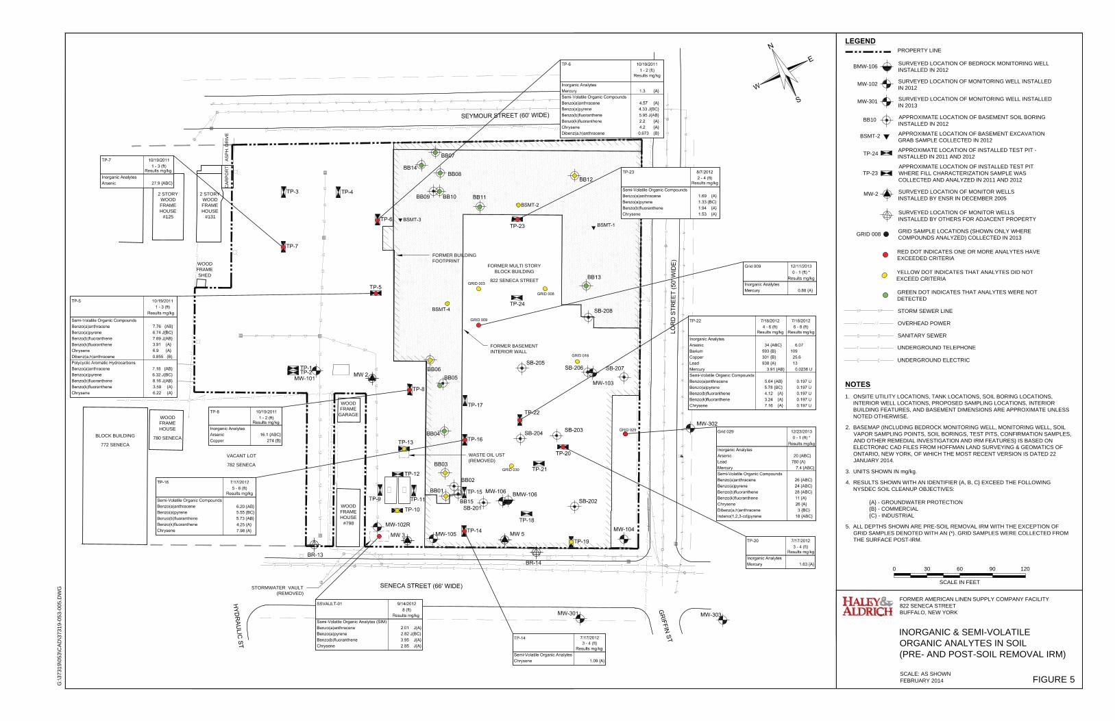
0 30 60 90 120
SCALE IN FEET
G:\3
7319
\053
\CA
D\3
7319
-053
-005
.DW
G
FIGURE 5
FORMER AMERICAN LINEN SUPPLY COMPANY FACILITY822 SENECA STREETBUFFALO, NEW YORK
INORGANIC & SEMI-VOLATILEORGANIC ANALYTES IN SOIL(PRE- AND POST-SOIL REMOVAL IRM)
SCALE: AS SHOWNFEBRUARY 2014
LEGEND
SURVEYED LOCATION OF MONITOR WELLSINSTALLED BY ENSR IN DECEMBER 2005
SURVEYED LOCATION OF MONITOR WELLSINSTALLED BY OTHERS FOR ADJACENT PROPERTY
MW-2
PROPERTY LINE
APPROXIMATE LOCATION OF INSTALLED TEST PIT -INSTALLED IN 2011 AND 2012
MW-102
TP-24
SURVEYED LOCATION OF MONITORING WELL INSTALLEDIN 2012
SURVEYED LOCATION OF BEDROCK MONITORING WELLINSTALLED IN 2012BMW-106
NOTES1. ONSITE UTILITY LOCATIONS, TANK LOCATIONS, SOIL BORING LOCATIONS,
INTERIOR WELL LOCATIONS, PROPOSED SAMPLING LOCATIONS, INTERIORBUILDING FEATURES, AND BASEMENT DIMENSIONS ARE APPROXIMATE UNLESSNOTED OTHERWISE.
2. BASEMAP (INCLUDING BEDROCK MONITORING WELL, MONITORING WELL, SOILVAPOR SAMPLING POINTS, SOIL BORINGS, TEST PITS, CONFIRMATION SAMPLES,AND OTHER REMEDIAL INVESTIGATION AND IRM FEATURES) IS BASED ONELECTRONIC CAD FILES FROM HOFFMAN LAND SURVEYING & GEOMATICS OFONTARIO, NEW YORK, OF WHICH THE MOST RECENT VERSION IS DATED 22JANUARY 2014.
3. UNITS SHOWN IN mg/kg.
4. RESULTS SHOWN WITH AN IDENTIFIER {A, B, C} EXCEED THE FOLLOWINGNYSDEC SOIL CLEANUP OBJECTIVES:
{A} - GROUNDWATER PROTECTION{B} - COMMERCIAL{C} - INDUSTRIAL
5. ALL DEPTHS SHOWN ARE PRE-SOIL REMOVAL IRM WITH THE EXCEPTION OF GRID SAMPLES DENOTED WITH AN (*). GRID SAMPLES WERE COLLECTED FROM THE SURFACE POST-IRM.
BB10 APPROXIMATE LOCATION OF BASEMENT SOIL BORINGINSTALLED IN 2012
BSMT-2 APPROXIMATE LOCATION OF BASEMENT EXCAVATIONGRAB SAMPLE COLLECTED IN 2012
RED DOT INDICATES ONE OR MORE ANALYTES HAVEEXCEEDED CRITERIA
GREEN DOT INDICATES THAT ANALYTES WERE NOTDETECTED
APPROXIMATE LOCATION OF INSTALLED TEST PITWHERE FILL CHARACTERIZATION SAMPLE WASCOLLECTED AND ANALYZED IN 2011 AND 2012
TP-23
FORMER MULTI STORYBLOCK BUILDING
822 SENECA STREET
FORMER BUILDINGFOOTPRINT
STORM SEWER LINE
SANITARY SEWER
UNDERGROUND TELEPHONE
UNDERGROUND ELECTRIC
OVERHEAD POWER
FORMER BASEMENTINTERIOR WALL
YELLOW DOT INDICATES THAT ANALYTES DID NOTEXCEED CRITERIA
MW-301 SURVEYED LOCATION OF MONITORING WELL INSTALLEDIN 2013
GRID SAMPLE LOCATIONS (SHOWN ONLY WHERECOMPOUNDS ANALYZED) COLLECTED IN 2013GRID 008
VACANT LOT
782 SENECA
BLOCK BUILDING
772 SENECA
WOODFRAMEHOUSE
780 SENECA
WOODFRAMESHED
2 STORYWOODFRAMEHOUSE
#125
2 STORYWOODFRAMEHOUSE
#131
WOODFRAMEHOUSE
#798
WOODFRAME
GARAGE
CA
RP
OR
TA
SP
H. D
RIV
E
STORMWATER VAULT(REMOVED)
WASTE OIL UST(REMOVED)

0 30 60 90 120
SCALE IN FEET
G:\3
7319
\053
\CA
D\3
7319
-053
-006
.DW
G
FIGURE 6
FORMER AMERICAN LINEN SUPPLY COMPANY822 SENECA STREETBUFFALO, NEW YORK
PRE-SOIL REMOVAL IRM VOLATILEORGANIC COMPOUNDS IN SOIL
SCALE: AS SHOWNFEBRUARY 2014
LEGEND
SURVEYED LOCATION OF MONITOR WELLSINSTALLED BY ENSR IN DECEMBER 2005
SURVEYED LOCATION OF MONITOR WELLSINSTALLED BY OTHERS FOR ADJACENT PROPERTY
BR-14
MW-2
PROPERTY LINE
APPROXIMATE LOCATION OF INSTALLED TEST PIT
MW-102
TP-24
SURVEYED LOCATION OF MONITORING WELL INSTALLEDIN 2012
SURVEYED LOCATION OF BEDROCK MONITORING WELLINSTALLED IN 2012
BMW-106
NOTES1. ONSITE UTILITY LOCATIONS, TANK LOCATIONS, SOIL BORING LOCATIONS,
INTERIOR WELL LOCATIONS, PROPOSED SAMPLING LOCATIONS, INTERIORBUILDING FEATURES, AND BASEMENT DIMENSIONS ARE APPROXIMATE UNLESSNOTED OTHERWISE.
2. BASEMAP (INCLUDING BEDROCK MONITORING WELL, MONITORING WELL, SOILVAPOR SAMPLING POINTS, SOIL BORINGS, TEST PITS, CONFIRMATION SAMPLES,AND OTHER REMEDIAL INVESTIGATION AND IRM FEATURES) IS BASED ONELECTRONIC CAD FILES FROM HOFFMAN LAND SURVEYING & GEOMATICS OFONTARIO, NEW YORK, OF WHICH THE MOST RECENT VERSION IS DATED 22JANUARY 2014.
3. UNITS SHOWN IN mg/kg.
4. RESULTS SHOWN WITH AN IDENTIFIER {A, B, C} EXCEED THE FOLLOWINGNYSDEC SOIL CLEANUP OBJECTIVES:
{A} - GROUNDWATER PROTECTION{B} - COMMERCIAL{C} - INDUSTRIAL
BB10 APPROXIMATE LOCATION OF INSTALLED BASEMENT SOILBORING
BSMT-2 APPROXIMATE LOCATION OF BASEMENT EXCAVATIONGRAB SAMPLE
RED DOT INDICATES ONE OR MORE COMPOUNDSHAVE EXCEEDED CRITERIA
GREEN DOT INDICATES THAT COMPOUNDS WERENOT DETECTED
STORM SEWER LINE
SANITARY SEWER
UNDERGROUND TELEPHONE
UNDERGROUND ELECTRIC
OVERHEAD POWER
FORMER BUILDINGFOOTPRINT
FORMER BASEMENTINTERIOR WALL
YELLOW DOT INDICATES THAT COMPOUNDS DID NOTEXCEED CRITERIA
MW-301 SURVEYED LOCATION OF MONITORING WELL INSTALLEDIN 2013
ASH-E APPROXIMATE LOCATION OF PRE-CHARATERIZATIONGRAB SAMPLE OF ASH LAYER COLLECTED IN 2012
FORMER MULTI STORYBLOCK BUILDING
822 SENECA STREET
VACANT LOT
782 SENECA
BLOCK BUILDING
772 SENECA
WOODFRAMEHOUSE
780 SENECA
WOODFRAMESHED
2 STORYWOODFRAMEHOUSE
#125
2 STORYWOODFRAMEHOUSE
#131
WOODFRAMEHOUSE
#798
WOODFRAME
GARAGE
APPROXIMATE LOCATION OF BASEMENT IRM SOILCONFIRMATION SAMPLE COLLECTED IN 2012SS-01

0 30 60 90 120
SCALE IN FEET
G:\3
7319
\053
\CA
D\3
7319
-053
-008
.DW
G
FIGURE 7
FORMER AMERICAN LINEN SUPPLY COMPANY822 SENECA STREETBUFFALO, NEW YORK
VOLATILE ORGANIC COMPOUNDS INSOIL VAPOR, SUB-SLAB VAPOR,INDOOR AIR, AND OUTDOOR AIR
SCALE: AS SHOWNFEBRUARY 2014
LEGENDPROPERTY LINE
SURVEYED LOCATION OF SOIL VAPOR SAMPLING POINTINSTALLED IN 2012
SV-3
1. ONSITE UTILITY LOCATIONS, TANK LOCATIONS, SOIL BORING LOCATIONS,INTERIOR WELL LOCATIONS, PROPOSED SAMPLING LOCATIONS, INTERIORBUILDING FEATURES, AND BASEMENT DIMENSIONS ARE APPROXIMATE UNLESSNOTED OTHERWISE.
2. BASEMAP (INCLUDING BEDROCK MONITORING WELL, MONITORING WELL, SOILVAPOR SAMPLING POINTS, SOIL BORINGS, TEST PITS, CONFIRMATION SAMPLES,AND OTHER REMEDIAL INVESTIGATION AND IRM FEATURES) IS BASED ONELECTRONIC CAD FILES FROM HOFFMAN LAND SURVEYING & GEOMATICS OFONTARIO, NEW YORK, OF WHICH THE MOST RECENT VERSION IS DATED 22JANUARY 2014.
3. UNITS SHOWN IN µg/m3.
4. DETECTED CHEMICALS SHOWN IN DATABOXES.
5. SV-1 THROUGH SV-4 WERE INSTALLED AS PART OF THE 2012 FIELD ACTIVITIES. SV-3AND SV-4 DID NOT YIELD SOIL VAPOR SAMPLES DUE TO THE APPARENT PRESENCE OFWATER IN THE SAMPLE PORT.
NOTES
FORMER MULTI STORYBLOCK BUILDING
822 SENECA STREET
FORMER BUILDINGFOOTPRINT
STORM SEWER LINE
SANITARY SEWER
UNDERGROUND TELEPHONE
UNDERGROUND ELECTRIC
OVERHEAD POWER
FORMER BASEMENTINTERIOR WALL
(NOT SAMPLED)
(NOT SAMPLED)
APPROXIMATE LOCATION OF SOIL VAPOR SAMPLING POINTINSTALLED IN 2013
APPROXIMATE LOCATION OF AMBIENT AIR SAMPLE IN 2013
APPROXIMATE LOCATION OF INDOOR AIR SAMPLE IN 2013
SS798
OA798
IA798
VACANT LOT
782 SENECA
BLOCK BUILDING
772 SENECA
WOODFRAMEHOUSE
780 SENECA
WOODFRAMESHED
2 STORYWOODFRAMEHOUSE
#125
2 STORYWOODFRAMEHOUSE
#131
WOODFRAMEHOUSE
#798
WOODFRAME
GARAGE
CA
RP
OR
TA
SP
H. D
RIV
E
STORMWATER VAULT(REMOVED)
WASTE OIL UST(REMOVED)

HYD
RAU
LIC ST
SEYMOUR STREET (60' WIDE)
LOR
D S
TRE
ET
(50'
WID
E)
GR
IFFIN ST
SENECA STREET (66' WIDE)
(DESTROYED2013)
EXISTING STORM SEWER
FORMER BUILDINGFOOTPRINT
MW-101
MW-102R
MW-301
MW-106
MW-303
MW-302
MW-103
MW-104MW 5
MW 2
MW 3
BR-14
BR-13
BMW-106
LEGEND
1. ONSITE UTILITY LOCATIONS, TANK LOCATIONS, SOIL BORING LOCATIONS, INTERIOR WELL LOCATIONS,PROPOSED SAMPLING LOCATIONS, INTERIOR BUILDING FEATURES, AND BASEMENT DIMENSIONS AREAPPROXIMATE UNLESS NOTED OTHERWISE.
2. BASEMAP (INCLUDING BEDROCK MONITORING WELL, MONITORING WELL, SOIL VAPOR SAMPLING POINTS,SOIL BORINGS, TEST PITS, CONFIRMATION SAMPLES, AND OTHER REMEDIAL INVESTIGATION AND IRMFEATURES) IS BASED ON ELECTRONIC CAD FILES FROM HOFFMAN LAND SURVEYING & GEOMATICS OFONTARIO, NEW YORK, OF WHICH THE MOST RECENT VERSION IS DATED 22 JANUARY 2014.”
NOTES
G:\3
7319
\053
\CA
D\3
7319
-053
-GS
E_C
ON
TS [2
014]
.DW
G
FIGURE 8
FORMER AMERICAN LINEN SUPPLY COMPANY FACILITY822 SENECA STREETBUFFALO, NEW YORK
POST-SOIL REMOVAL IRMEXTENT OF EXCAVATION
SCALE: AS SHOWNFEBRUARY 2014
0 30 60 90 120
SCALE IN FEET
PROPERTY LINE
STORM SEWER LINE
SANITARY SEWER
UNDERGROUND TELEPHONE
UNDERGROUND ELECTRIC
OVERHEAD POWER
APPROXIMATE EXTENTS OF IRMEXCAVATION AREA AND DISTURBANCE
SURVEYED LOCATION OF MONITOR WELLSINSTALLED BY ENSR IN DECEMBER 2005.
SURVEYED LOCATION OF MONITOR WELLSINSTALLED BY OTHERS FOR ADJACENT PROPERTY.
BR-13
MW-2
MW-102 SURVEYED LOCATION OF MONITORING WELL INSTALLEDIN 2012
SURVEYED LOCATION OF BEDROCK MONITORING WELLINSTALLED IN 2012BMW-106
MW-301 SURVEYED LOCATION OF MONITORING WELL INSTALLEDIN 2013
STORMWATER VAULT(REMOVED)
WASTE OIL UST(REMOVED)
TP-18APPROXIMATEEXCAVATIONEXTENTS
TP-16APPROXIMATE
EXCAVATIONEXTENTS
WASTE OIL USTEXCAVATION EXTENTS
STORMWATER VAULTEXCAVATION EXTENTS

H
Y
D
R
A
U
LIC
S
T
SEYMOUR STREET (60' WIDE)
LO
RD
S
TR
EE
T (50' W
ID
E)
G
R
IF
F
IN
S
T
SENECA STREET (66' WIDE)
EXISTING STORM SEWER
TP-19
TP-21
TP-20
TP-23
TP-24
TP-22
TP-15
TP-10
TP-11
TP-9
TP-13
TP-17
TP-8
TP-1
TP-2
TP-5
TP-7
TP-6
TP-4TP-3
FORMER BASEMENT
INTERIOR WALL
FORMER BUILDING
FOOTPRINT
GRID 001 GRID 002
GRID 003 GRID 004 GRID 005
GRID 006 GRID 007 GRID 008
GRID 009 GRID 010 GRID 011
GRID 012
GRID 015 GRID 016 GRID 017
GRID 013 GRID 014
GRID 018 GRID 019
GRID 020
GRID 021 GRID 022 GRID 023 GRID 024
GRID 025
GRID 026
GRID 027
GRID 028 GRID 029
GRID 030
GRID 031
GRID 032 GRID 033
GRID 034
GRID 035
GRID 036
GRID 041
GRID 042
GRID 037
GRID 043
GRID 038
GRID 039
GRID 040
GRID 044
GRID 045GRID 046
NORTH WALL
EAST WALL
SOUTH WALL
WEST WALL
NORTH WALL
EAST WALL
SOUTH WALL
WEST WALL
BOTTOM
TP-14
WEST WALL
SOUTH WALL
EAST WALL
NORTH WALL
BOTTOM
LEGEND
NOTES
G:\37
319
\05
3\C
AD
\37319-0
53-009_R
1.D
WG
FIGURE 9
FORMER AMERICAN LINEN SUPPLY COMPANY FACILITY
822 SENECA STREET
BUFFALO, NEW YORK
POST-SOIL REMOVAL IRM
CONFIRMATION SAMPLES AND
PROPOSED EXCAVATION PLAN
SCALE: AS SHOWN
MAY 2014
RED DOT INDICATES APPROXIMATE LOCATION OF SAMPLE
COLLECTED DURING THE RI/IRM WHERE ONE OR MORE TARGET
CVOC COMPOUNDS WERE DETECTED ABOVE CRITERIA AS SHOWN.
YELLOW DOT INDICATES APPROXIMATE LOCATION OF SAMPLE COLLECTED DURING THE
RI/IRM WHERE TARGET CVOC COMPOUNDS WERE NOT DETECTED ABOVE CRITERIA.
GREEN DOT INDICATES APPROXIMATE LOCATION OF SAMPLE COLLECTED
DURING THE RI/IRM WHERE TARGET CVOC COMPOUNDS WERE NOT DETECTED.
0 30 60 90 120
SCALE IN FEET
PROPERTY LINE
APPROXIMATE LOCATION OF INSTALLED TEST PITTP-24
STORM SEWER LINE
SANITARY SEWER
UNDERGROUND TELEPHONE
UNDERGROUND ELECTRIC
OVERHEAD POWER
VOLATILE ORGANIC COMPOUND
SITE SPECIFIC
PROTECTION OF
GROUNDWATER SCOs
(MG/KG)
TETRACHLOROETHENE 1.8
TRICHLOROETHENE 0.75
CIS-1,2-DICHLOROETHENE0.25
VINYL CHLORIDE 0.02
POTENTIAL REMEDIAL ACTION EXCAVATION AREAS, BASED ON 2013 SOIL
REMOVAL IRM CONFIRMATION SAMPLING RESULTS.
APPROXIMATE AREA : 13,500 SQ.FT.
APPROXIMATE LOCATION OF GRID SAMPLES
GRID 001
VACANT LOT
782 SENECA
2 STORY
WOOD
FRAME
HOUSE
#131
WOOD
FRAME
HOUSE
#798
WOOD
FRAME
GARAGE
CA
RP
OR
TA
SP
H. D
RIV
E
WOOD
FRAME
HOUSE
780 SENECA
2 STORY
WOOD
FRAME
HOUSE
#125
1. ONSITE UTILITY LOCATIONS, TANK LOCATIONS, SOIL BORING LOCATIONS, INTERIOR WELL
LOCATIONS, PROPOSED SAMPLING LOCATIONS, INTERIOR BUILDING FEATURES, AND BASEMENT
DIMENSIONS ARE APPROXIMATE UNLESS NOTED OTHERWISE.
2. BASEMAP (INCLUDING BEDROCK MONITORING WELL, MONITORING WELL, SOIL VAPOR SAMPLING
POINTS, SOIL BORINGS, TEST PITS, CONFIRMATION SAMPLES, AND OTHER REMEDIAL
INVESTIGATION AND IRM FEATURES) IS BASED ON ELECTRONIC CAD FILES FROM HOFFMAN LAND
SURVEYING & GEOMATICS OF ONTARIO, NEW YORK, OF WHICH THE MOST RECENT VERSION IS
DATED 22 JANUARY 2014.
3. SURFACE SAMPLES WERE COLLECTED FROM THE 0 TO 6-INCH INTERVAL, BASED ON POST-IRM
GROUND SURFACE ELEVATIONS
4. ONLY CHEMICALS SCREENED AGAINST CRITERIA INCLUDE TETRACHLOROETHENE,
TRICHLOROETHENE, CIS-1,2-DICHLOROETHENE, AND VINYL CHLORIDE.
5. ONLY RESULT THAT EXCEED CRITERIA ARE SHOWN ON FIGURE.
6. RESULTS SHOWN WITH AN IDENTIFIER {A} EXCEED THE
FOLLOWING NYSDEC SOIL CLEANUP OBJECTIVES (SCOs):
{A} - SITE SPECIFIC GROUNDWATER PROTECTION
TP-18
APPROXIMATE
EXCAVATION EXTENTS
TP-16
APPROXIMATE
EXCAVATION EXTENTS
WASTE OIL UST
APPROXIMATE EXCAVATION EXTENTS
STORMWATER VAULT
APPROXIMATE EXCAVATION EXTENTS
STORMWATER VAULT
(REMOVED)
WASTE OIL UST
(REMOVED)

HYD
RAU
LIC ST
SEYMOUR STREET (60' WIDE)
LOR
D S
TRE
ET
(50'
WID
E)
GR
IFFIN ST
SENECA STREET (66' WIDE)
MW 2
MW 5MW 3
MW-101
MW-104
BMW-106
MW-103
MW-105
MW-106
EXISTING STORM SEWER
ENTRANCE GATE EXIT GATE
MW-302
MW-303MW-301
EXISTING ASPHALT AREA; SEALCRACKS (FIELD DETERMINED), TYP.
ASPHALT PATCH AREAS(FIELD DETERMINED), TYP.
582.
50
585.
00
585.
50
584.
5058
3.00
FINAL GRADE AS SHOWN ON THISFIGURE AND SEED.
PLACE DEMARCATION LAYER, PLACE 1FT CLEAN COVER, FINAL GRADE ASSHOWN, AND SEED.
584.
00
583.5
0
0
SCALE IN FEET
30 60 90 120
LEGEND
SURVEYED LOCATION OF BEDROCK MONITORING WELL INSTALLED IN 2012
SURVEYED LOCATION OF MONITORING WELL INSTALLED IN 2012 AND 2013
SURVEYED LOCATION OF MONITOR WELLSINSTALLED BY ENSR IN DECEMBER 2005
SURVEYED LOCATION OF MONITOR WELLSINSTALLED BY OTHERS FOR ADJACENT PROPERTY.
PROPERTY AND FENCE LINE
1. ONSITE UTILITY LOCATIONS, TANK LOCATIONS, FORMER BUILDING FEATURES,AND FORMER BASEMENT DIMENSIONS ARE APPROXIMATE UNLESS NOTEDOTHERWISE.
2. BASEMAP (INCLUDING BEDROCK MONITORING WELL, MONITORING WELL, SOILVAPOR SAMPLING POINTS, SOIL BORINGS, TEST PITS, CONFIRMATION SAMPLES,AND OTHER REMEDIAL INVESTIGATION AND IRM FEATURES) IS BASED ONELECTRONIC CAD FILES FROM HOFFMAN LAND SURVEYING & GEOMATICS OFONTARIO, NEW YORK, OF WHICH THE MOST RECENT VERSION IS DATED 22JANUARY 2014.
NOTES
FORMER BUILDING FOOTPRINT
STORM SEWER LINE
SANITARY SEWER LINE
WATER LINE
UNDERGROUND TELEPHONE LINE
OVERHEAD TELEPHONE LINE
ELECTRICAL LINE
AREA FOR PLACEMENT OF DEMARCATION LAYER & 1 FT CLEAN COVER, &SEED
G:\3
7319
\053
\CA
D\3
7319
-053
-010
_AA
R_F
INA
L_G
RA
DE
.DW
G
FIGURE 10
FORMER AMERICAN LINEN SUPPLY COMPANY FACILITY822 SENECA STREETBUFFALO, NEW YORK
PROPOSED FINAL GRADING PLAN
SCALE: AS SHOWNFEBRUARY 2014
AREA (PREVIOUSLY BACKFILLED TO GRADE) FOR FINAL GRADING & SEED ;DEMARCATION LAYER NOT REQUIRED
SURVEYED LOCATION OF OFF-SITE MONITORING WELL INSTALLED IN 2013
MW-103
MW-303
ASPHALT PATCH AREA (FIELD DETERMINED)
VACANT LOT
782 SENECA
WOODFRAMESHED
2 STORYWOODFRAMEHOUSE
#131
WOODFRAMEHOUSE
#798
WOODFRAME
GARAGE
CA
RP
OR
TA
SP
H. D
RIV
E
ASPHALTAREA
ASPHALTAREA
CONC.PAD
ASPHALTAREA

APPENDIX A
Soil & Groundwater Management Plan

APPENDIX A
SOIL & GROUNDWATER MANAGEMENT PLAN
I. Introduction
The following Soil & Groundwater Management Plan provides guidance for managing excavations,
soil, and groundwater at the Former American Linen Supply Co. Facility BCP site during the Remedial
Action (RA) activities. The guidance herein is a companion to the Remedial Action Work Plan (RAWP)
and complies with the criteria for a Track 4 – commercial use cleanup track. This guidance is based on
the May 2010 DER-10 Technical Guidance for Site Investigation and Remediation.
The RA work will be conducted with oversight by Haley & Aldrich personnel. All excavations will be
screened visually and with a photoionization detector (PID) to facilitate soil/fill segregation for
disposal, or analytical testing for potential onsite reuse.
Community air monitoring will be conducted in accordance with the New York State Department of
Health (NYSDOH) Community Air Monitoring Plan (CAMP) during excavation activities. A copy of
the generic CAMP is included in Appendix B. Haley & Aldrich personnel will work under the existing
Health & Safety Plan (HASP) completed for the Soil Excavation Interim Remedial Measure conducted
in October 2013 through January 2014.
II. Stockpiling Methods
Soil will be placed in approximately 100 ton stockpiles comprised of materials from designated sections
as described in the RAWP. The piles will be sampled and analyzed for offsite disposal per Section III
below.
III. Sampling Methods
Sample frequency and procedure will be done as follows. Sample results will be compared to the
NYSDEC commercial use soil cleanup objectives (SCOs), protection of groundwater SCOs (including
the site-specific derived protection of groundwater SCO for PCE), EPA Maximum Concentrations of
Contaminants for the Toxicity Characteristic (TCLP metals, only), and/or the TAGM 3028 contained-in
thresholds (VOCs, only). The regulatory standards are shown in the attached Table A-1. Sampling will
occur as follows:
a. Excavated impacted materials will be stockpiled in approximately 100 ton piles. For each
stockpile, the following samples will be collected:
i. Two (2) discrete samples for VOCs from each pile
ii. One (1) composite sample for TCLP Metals from multiple piles totaling up to 500
tons.
b. The samples will be analyzed at the laboratory and disposed according to Section IV below.
If necessary, and based on the results, approval for contained-in determination will be
obtained from the NYSDEC if VOC results indicate that pile is a listed hazardous waste but
the concentrations are below NYSDEC TAGM 3028 thresholds.
c. Note that additional sample parameters may be required by the receiving facility.

IV. Disposal Methods
The NYSDOH CAMP will be enacted during materials load out for disposal. Stockpiles will be
disposed of offsite based on the analytical results from Section III above as follows:
a. If TCLP results indicate that the materials are characteristically hazardous and/or VOCs are
detected above TAGM 3028 thresholds, dispose offsite as hazardous waste in accordance
with disposal facility requirements.
b. If TCLP results indicate that the materials are characteristically non-hazardous, and VOC
sampling indicated dry cleaning solvents detected but below TAGM 3028 thresholds,
submit the results to the NYSDEC for TAGM 3028 contained-in approval and dispose
offsite at a non-hazardous waste landfill once approved per disposal facility requirements. If
the VOC results do not meet the TAGM 3028 thresholds, dispose at a hazardous waste
landfill.
c. If TCLP results indicate that the materials are characteristically non-hazardous, and dry
cleaning solvent related VOCs are not detected (i.e. the material is not a listed hazardous
waste), dispose of offsite at a non-hazardous waste landfill in accordance with disposal
facility requirements.
Disposal weight tickets, bills of lading/manifests will be collected by Haley & Aldrich field personnel
for inclusion in the Final Engineering Report.
V. Excavation Dewatering
Water encountered in the excavation will be staged in tanks, tested, treated if necessary, and discharged
to the City of Buffalo Sewer via a Temporary Discharge Permit.
VI. Backfill
Backfill may consist of the following materials described in the sections below based on their intended
use.
a. Clean Cover – The following materials meeting the criteria for Clean Cover and may be
used onsite above the demarcation layer.
i. Onsite, non-impacted material (Section II.b above) tested in accordance with
Section III.a above that meet lesser of the protection of groundwater or commercial
use SCOs.
ii. Gravel, rock, or stone, consisting of virgin material from a permitted mine or
quarry.
iii. Imported soil or cover, other than described in VI.a.ii above, that meets the testing
requirements from the May 2010 DER-10 section 5.4(e)3.
iv. Non-impacted concrete (Section II.a above) or recycled concrete or brick from a
NYSDEC registered construction and demolition debris processing facility if the
material conforms to the requirements of Section 304 of the New York State
Department of Transportation Standard Specifications Construction and Materials
Volume 1 (2002).

b. Materials below the demarcation layer or pavement – Non-impacted material (Section II.b)
that when tested in accordance with Section III.a above meet the protection of groundwater
SCOs but may not meet the commercial use SCOs (e.g. elevated concentrations of metals)
may be reused onsite below the demarcation layer or pavement layer.

2/27/2014
TABLE A-1 - APPLICABLE REGULATORY TESTING CRITERIAFORMER AMERICAN LINEN SUPPLY CO. FACILITYBUFFALO, NEW YORKNYSDEC SITE # C915241
Metals
Arsenic 16 2 16 2 3-12 5 --
Barium 820 400 15-600 100 --
Beryllium 47 590 0-1.75 -- --
Cadmium 7.5 9.3 0.1-1 1 --Chromium, hexavalent1 19 400 1.5-40 -- --Chromium, trivalent1 -- 1500 1.5-40 5 --
Copper 1720 270 1-50 -- --Total Cyanide1
40 27 -- -- --
Lead 450 1000 200-500 5 --
Manganese 2000 2 10000 50-5000 -- --
Total Mercury 0.73 2.8 0.001-0.2 0.2 --
Nickel 130 310 0.5-25 -- --
Selenium 4 2 1500 0.1-3.9 1 --
Silver 8.3 1500 -- 5 --
Zinc 2480 10000 9-50 -- --
Volatile Organic Compounds
1,1,1-Trichloroethane 0.68 500 -- -- 7000
1,1-Dichloroethane 0.27 240 -- -- 8000
1,1-Dichloroethene 0.33 500 -- -- 120
1,2-Dichlorobenzene 1.1 500 -- -- 7000
1,2-Dichloroethane 0.02 230 -- -- 7.7
cis-1,2-Dichloroethene 0.25 500 -- -- 800
trans-1,2-Dichloroethene 0.19 500 -- -- 2000
1,3-Dichlorobenzene 2.4 280 -- -- --
1,4-Dichlorobenzene 1.8 130 -- -- 29
1,4-Dioxane 0.1 3 130 -- -- 64
Acetone 0.05 500 -- -- 8000
Benzene 0.06 44 -- -- 24
Butylbenzene 12 500 -- -- --
Carbon tetrachloride 0.76 22 -- -- 5.4
Chlorobenzene 1.1 500 -- -- 2000
Chloroform 0.37 350 -- -- 110
Ethylbenzene 1 390 -- -- 6000
Hexachlorobenzene 3.2 6 -- -- 0.41
Methyl ethyl ketone 0.12 500 -- -- 4000
Methyl tert-butyl ether 0.93 500 -- -- --
Methylene Chloride 0.05 500 -- -- 93
n-Propylbenzene 3.9 500 -- -- --
sec-Butylbenzene 11 500 -- -- --
tert-Butylbenzene 5.9 500 -- -- --
Tetrachloroethane 1.3 150 -- -- 14
Toluene 0.7 500 -- -- 20000
Trichloroethene 0.47 200 -- -- 640
1,2,4-Trimethylbenzene 3.6 190 -- -- --
1,3,5-Trimethylbenzene 8.4 190 -- -- --
Vinyl Chloride 0.02 13 -- -- 0.36Xylene (mixed) 1.6 500 -- -- 200000
TAGM 3028(VOCs, Only)
(mg/kg)
Disposal Criteria for Potentially Hazardous Waste4Soil Cleanup/Reuse Criteria
NYSDEC Soil Cleanup Objectives (Restricted Use) Eastern United States
Background Levels(mg/kg)Protection of
Groundwater (mg/kg)Commercial Use Criteria
(mg/kg)
EPA Regulatory Level(TCLP Metals, Only)
(mg/L)
Haley Aldrich of New YorkG:\37319 (AmeriPride, 8 Lord Street, Buffalo)\053 - RI_IRM_AAR Reporting\AAR_RAWP\Appendix A - SCO Table\2014_0106_Table A-1 Regulatory Criteria_F.xlsx Page 1 of 2

2/27/2014
TABLE A-1 - APPLICABLE REGULATORY TESTING CRITERIAFORMER AMERICAN LINEN SUPPLY CO. FACILITYBUFFALO, NEW YORKNYSDEC SITE # C915241
NOTES & ABBREVIATIONS:-- = No Standard or Value**The soil cleanup objectives herein are from the 6 NYCRR Part 375-6.8(b) dated 14 December 2006.The EPA regulatory levels are from the Code of Federal Regulations Maximum Concentration of Contaminants for Toxisity Characteristics.TAGM 3028 Action Leves are from the 30 November 1992 Memorandum 3028 regarding "Contained-In" Criteria for Environmental Media1. The SCO for this specific compound (or family of compounds) is considered to be met if the analysis for the total species of the contaminant is below the SCO2. For consituants where the calculated SCO was lower than the rural soil background concentration determined by the Department and Department of Health rural soil survey, the rural soil background concentration is used as the Track 2 SCO value for this use of the site.3. For constituents were the calculated SCO was lower than the contract required quantitation limit (CRQL), the CRQL is used as the SCO value.4. Additional sampling criteria may be required by the receiving facility.
Haley Aldrich of New YorkG:\37319 (AmeriPride, 8 Lord Street, Buffalo)\053 - RI_IRM_AAR Reporting\AAR_RAWP\Appendix A - SCO Table\2014_0106_Table A-1 Regulatory Criteria_F.xlsx Page 2 of 2
APPENDIX B
NYSDOH Generic Community Air Monitoring Plan

NYSDOH gCAMP rev 1 06/00
Page 1 of 3
New York State Department of Health
Generic Community Air Monitoring Plan
A Community Air Monitoring Plan (CAMP) requires real-time monitoring for volatile organic compounds (VOCs) and particulates (i.e., dust) at the downwind perimeter of each designated work area when certain activities are in progress at contaminated sites. The CAMP is not intended for use in establishing action levels for worker respiratory protection. Rather, its intent is to provide a measure of protection for the downwind community (i.e., off-site receptors including residences and businesses and on-site workers not directly involved with the subject work activities) from potential airborne contaminant releases as a direct result of investigative and remedial work activities. The action levels specified herein require increased monitoring, corrective actions to abate emissions, and/or work shutdown. Additionally, the CAMP helps to confirm that work activities did not spread contamination off-site through the air. The generic CAMP presented below will be sufficient to cover many, if not most, sites. Specific requirements should be reviewed for each situation in consultation with NYSDOH to ensure proper applicability. In some cases, a separate site-specific CAMP or supplement may be required. Depending upon the nature of contamination, chemical- specific monitoring with appropriately-sensitive methods may be required. Depending upon the proximity of potentially exposed individuals, more stringent monitoring or response levels than those presented below may be required. Special requirements will be necessary for work within 20 feet of potentially exposed individuals or structures and for indoor work with co-located residences or facilities. These requirements should be determined in consultation with NYSDOH. Reliance on the CAMP should not preclude simple, common-sense measures to keep VOCs, dust, and odors at a minimum around the work areas.
Community Air Monitoring Plan
Depending upon the nature of known or potential contaminants at each site, real-time air monitoring for volatile organic compounds (VOCs) and/or particulate levels at the perimeter of the exclusion zone or work area will be necessary. Most sites will involve VOC and particulate monitoring; sites known to be contaminated with heavy metals alone may only require particulate monitoring. If radiological contamination is a concern, additional monitoring requirements may be necessary per consultation with appropriate NYSDEC/NYSDOH staff.
Continuous monitoring will be required for all ground intrusive activities and during the demolition of contaminated or potentially contaminated structures. Ground intrusive activities include, but are not limited to, soil/waste excavation and handling, test pitting or trenching, and the installation of soil borings or monitoring wells.

NYSDOH gCAMP rev 1 06/00
Page 2 of 3
Periodic monitoring for VOCs will be required during non-intrusive activities such as the collection of soil and sediment samples or the collection of groundwater samples from existing monitoring wells. “Periodic” monitoring during sample collection might reasonably consist of taking a reading upon arrival at a sample location, monitoring while opening a well cap or overturning soil, monitoring during well baling/purging, and taking a reading prior to leaving a sample location. In some instances, depending upon the proximity of potentially exposed individuals, continuous monitoring may be required during sampling activities. Examples of such situations include groundwater sampling at wells on the curb of a busy urban street, in the midst of a public park, or adjacent to a school or residence. VOC Monitoring, Response Levels, and Actions
Volatile organic compounds (VOCs) must be monitored at the downwind perimeter of the immediate work area (i.e., the exclusion zone) on a continuous basis or as otherwise specified. Upwind concentrations should be measured at the start of each workday and periodically thereafter to establish background conditions. The monitoring work should be performed using equipment appropriate to measure the types of contaminants known or suspected to be present. The equipment should be calibrated at least daily for the contaminant(s) of concern or for an appropriate surrogate. The equipment should be capable of calculating 15-minute running average concentrations, which will be compared to the levels specified below. • If the ambient air concentration of total organic vapors at the downwind perimeter of the
work area or exclusion zone exceeds 5 parts per million (ppm) above background for the 15-minute average, work activities must be temporarily halted and monitoring continued. If the total organic vapor level readily decreases (per instantaneous readings) below 5 ppm over background, work activities can resume with continued monitoring.
• If total organic vapor levels at the downwind perimeter of the work area or exclusion
zone persist at levels in excess of 5 ppm over background but less than 25 ppm, work activities must be halted, the source of vapors identified, corrective actions taken to abate emissions, and monitoring continued. After these steps, work activities can resume provided that the total organic vapor level 200 feet downwind of the exclusion zone or half the distance to the nearest potential receptor or residential/commercial structure, whichever is less - but in no case less than 20 feet, is below 5 ppm over background for the 15-minute average.
• If the organic vapor level is above 25 ppm at the perimeter of the work area, activities
must be shutdown.
All 15-minute readings must be recorded and be available for State (DEC and DOH) personnel to review. Instantaneous readings, if any, used for decision purposes should also be recorded.

NYSDOH gCAMP rev 1 06/00
Page 3 of 3
Particulate Monitoring, Response Levels, and Actions
Particulate concentrations should be monitored continuously at the upwind and downwind perimeters of the exclusion zone at temporary particulate monitoring stations. The particulate monitoring should be performed using real-time monitoring equipment capable of measuring particulate matter less than 10 micrometers in size (PM-10) and capable of integrating over a period of 15 minutes (or less) for comparison to the airborne particulate action level. The equipment must be equipped with an audible alarm to indicate exceedance of the action level. In addition, fugitive dust migration should be visually assessed during all work activities. • If the downwind PM-10 particulate level is 100 micrograms per cubic meter (mcg/m3)
greater than background (upwind perimeter) for the 15-minute period or if airborne dust is observed leaving the work area, then dust suppression techniques must be employed. Work may continue with dust suppression techniques provided that downwind PM-10 particulate levels do not exceed 150 mcg/m3 above the upwind level and provided that no visible dust is migrating from the work area.
• If, after implementation of dust suppression techniques, downwind PM-10 particulate
levels are greater than 150 mcg/m3 above the upwind level, work must be stopped and a re-evaluation of activities initiated. Work can resume provided that dust suppression measures and other controls are successful in reducing the downwind PM-10 particulate concentration to within 150 mcg/m3 of the upwind level and in preventing visible dust migration.
All readings must be recorded and be available for State (DEC and DOH) personnel to review. June 20, 2000 P:\Bureau\Common\CommunityAirMonitoringPlan (CAMP)\GCAMPR1.DOC