Embed Size (px)
Citation preview

ENGINEER - Vol. XLVII, No. 01, pp. [57-73], 2014© The Institution of Engineers, Sri LankaENGINEER - Vol. XLVII, No. 02, pp. [page range], 2014 © The Institution of Engineers, Sri Lanka
1 ENGINEER
Reviewing of Insulator Selection Criteria for Overhead Power Lines in Coastal Areas of Sri Lanka
A C S Wijayatilake
Abstract: At present porcelain and glass insulators are used for overhead power lines in Sri Lanka. Salt contamination on insulators of coastal lines assists leakage currents to passing over the insulator surface and cause insulator flashing over. Frequent power outages due to flashing over of insulators on overhead power lines are common in coastal areas and it reduces the reliability of the power system considerably. It has been observed that this problem is very severe in costal lines in dry zone of Sri Lanka especially in Puttalam, Mannar and Jaffna areas. Partial blackout caused by flashing over of insulators on 220kV transmission line running closer to the sea and across the Kalpitiya lagoon from Norochcholai coal plant to Veyangoda switching station shows the severity of this problem. Therefore it is timely requirement to review the insulator selection criteria for overhead power lines to find out mitigation measures against the flashing over of insulators due to marine pollution. This paper describes the mechanism of flashing over of insulators due to marine pollution and highlights the limitations of the presently following electrical standards for insulator selection based on field measurements and maintenance experience. It is emphasized that the most successful method that can be employed to determine the ideal insulator out of insulators made of different materials and of different shapes is to verify their performance by conducting long term field measurements at the exact environment. Apart from that the existing practices applied on distribution network to minimize insulator flashing over is evaluated technically and financially in order to identify the best solution. Application of new technology such as adaptation of polymeric insulators, insulator coating materials and applicable online insulator washing techniques are also investigated. The importance of type test reports named as artificial pollution tests to understand the pollution immunity of insulators is also discussed. The value of establishing insulator field testing stations in problematic areas is strongly recommended and the test techniques applicable in field evaluation of insulator performance are briefly explained.
1. Introduction The prime objective of the power utility is to provide a quality and reliable electricity supply to its customers. Therefore more attention is paid in planning, designing, implementation and operational activities to achieve the goal of higher quality as well as more reliable electricity supply. Overhead power lines are widely used in power transmission and distribution networks comparing with its counterpart, underground cables, due to economic reasons. In order to avoid system faults and ensure the safety of lives and equipment the current carrying conductors are separated from supporting structures (poles or lattice towers) by means of insulators. Overhead power lines are always subjected to the variations of climatic
conditions (rain, wind, sunlight, fog, humidity etc.) and pollution conditions (marine, chemical, industrial etc.). Climatic and pollution conditions determine the insulator performance. If insulation properties are not matched with the prevailing environmental and climatic factors it is possible to flash over between conductors and supporting structures along the insulator surface during transient overvoltage situations (lightning, faults, load rejection etc.). Most of the time similar insulator flashingovers are seen by protective relays as an earth fault and interrupt the
Eng. A.C.S. Wijayatilake, B.Sc. Eng. (Hons), Mphill, MIE (Sri Lanka), Presently Chief Engineer (Projects) RI, Ceylon Electricity Board.
ENGINEER57

1 ENGINEER
supply disturbing consumers. Therefore environmental factors (climatic and pollution conditions) prevailing throughout the line route should be strictly observed and evaluated during line designing process in selection of insulators for overhead lines. Though tropical climate is prevailing (intermittent heavy rain, high humidity, high temperature) in Sri Lanka, the entire country can be further divided into different climatic zones by considering clear variations in these factors. When insulator pollution categories are concerned the marine pollution is prominent and can be observed in power facilities constructed closer to the sea shore. Only few power transmission lines and Medium Voltage (MV) power distribution feeders are running closer to the sea shore but trippings reported on these lines due to transient earth faults are extremely high. This problem is severe in the coastal belt between Marawila to Jaffna. However, the situation is worse in Mannar, Puttalam and Jaffna areas. Since large scale thermal power stations are being constructed in sea shore, at least short lengths of their power dispatching lines have to be constructed closer to the sea shore, sometimes across lagoons. These bulk power transmitting lines cannot be avoided of exposing to the marine pollution. For example 220kV tower lines from Norochcholai power plants are constructed across the Kalpitiya lagoon and 132kV transmission line connecting Jaffna peninsula with the rest of the grid has been constructed across the Elephant pass lagoon. Since these lines carry a considerable amount of power, the temporary disconnection of these lines due to a transient fault results in isolation of the power plant from the rest of the grid. It may cause stability issues and may end up with a blackout. The recent example is the partial blackout caused due to the isolation of 300MW Norochcholei coal power plant due to the insulation flashing over of 220kV transmission line that is believed to be caused by salt contamination on insulators. Hence, it is timely requirement for review the existing insulator performance against the severity of environmental factors and provides guide lines necessary for
insulator selection for outdoor power facilities. This paper summarizes the reasons for frequent flashing over of insulators mounted on power lines in coastal areas, the presently adopted remedial measures with their advantages and disadvantages and provide guidance to identify the most technically and economically effective solution based on the maintenance experience and field measurements. This paper highlights the outcomes of the research carried out jointly by CEB and University of Peradeniya on insulator pollution [1,2] and outcomes of that study may be helpful for finding a solution to minimize the trippings noticed in power lines running in coastal areas due to sea pollution.
2. Reason for Frequent Trippings of Coastal Feeders In CEB, either porcelain or glass insulators are used for overhead power lines. Pin type insulators are used for concrete pole lines and insulator strings consisting of few Cap and pin insulators are used for steel tower lines. Sea breeze carries sea water droplets and they settle over the surface of insulators mounted on lines running closer to the sea shore. After evaporating the water salt dust remains on the insulator surface. It makes a conductive electrolyte media for leakage currents when mixing with moisture during light showers or foggy conditions. These leakage currents flowing through the electrolyte solution dissipate heat energy. The areas of the surface with high energy dissipation form dry bands over the insulation surface. This results in severe surface erosions on the insulator surface closer to the metal fittings. Partial arching occur within the dry band finally causes flashover by short circuiting the insulator. These leakage current paths can be visible clearly in the dawn or evenings at high humidity weather conditions. The cumulative effect of this leakage currents happening on several insulator sets activates the earth fault relays and disconnect feeders. When an insulator surface is polluted the power frequency withstand voltage reduces drastically and may cause flashovers even at nominal operating voltages. Similar spurious
ENGINEER 58

1 ENGINEER
supply disturbing consumers. Therefore environmental factors (climatic and pollution conditions) prevailing throughout the line route should be strictly observed and evaluated during line designing process in selection of insulators for overhead lines. Though tropical climate is prevailing (intermittent heavy rain, high humidity, high temperature) in Sri Lanka, the entire country can be further divided into different climatic zones by considering clear variations in these factors. When insulator pollution categories are concerned the marine pollution is prominent and can be observed in power facilities constructed closer to the sea shore. Only few power transmission lines and Medium Voltage (MV) power distribution feeders are running closer to the sea shore but trippings reported on these lines due to transient earth faults are extremely high. This problem is severe in the coastal belt between Marawila to Jaffna. However, the situation is worse in Mannar, Puttalam and Jaffna areas. Since large scale thermal power stations are being constructed in sea shore, at least short lengths of their power dispatching lines have to be constructed closer to the sea shore, sometimes across lagoons. These bulk power transmitting lines cannot be avoided of exposing to the marine pollution. For example 220kV tower lines from Norochcholai power plants are constructed across the Kalpitiya lagoon and 132kV transmission line connecting Jaffna peninsula with the rest of the grid has been constructed across the Elephant pass lagoon. Since these lines carry a considerable amount of power, the temporary disconnection of these lines due to a transient fault results in isolation of the power plant from the rest of the grid. It may cause stability issues and may end up with a blackout. The recent example is the partial blackout caused due to the isolation of 300MW Norochcholei coal power plant due to the insulation flashing over of 220kV transmission line that is believed to be caused by salt contamination on insulators. Hence, it is timely requirement for review the existing insulator performance against the severity of environmental factors and provides guide lines necessary for
insulator selection for outdoor power facilities. This paper summarizes the reasons for frequent flashing over of insulators mounted on power lines in coastal areas, the presently adopted remedial measures with their advantages and disadvantages and provide guidance to identify the most technically and economically effective solution based on the maintenance experience and field measurements. This paper highlights the outcomes of the research carried out jointly by CEB and University of Peradeniya on insulator pollution [1,2] and outcomes of that study may be helpful for finding a solution to minimize the trippings noticed in power lines running in coastal areas due to sea pollution.
2. Reason for Frequent Trippings of Coastal Feeders In CEB, either porcelain or glass insulators are used for overhead power lines. Pin type insulators are used for concrete pole lines and insulator strings consisting of few Cap and pin insulators are used for steel tower lines. Sea breeze carries sea water droplets and they settle over the surface of insulators mounted on lines running closer to the sea shore. After evaporating the water salt dust remains on the insulator surface. It makes a conductive electrolyte media for leakage currents when mixing with moisture during light showers or foggy conditions. These leakage currents flowing through the electrolyte solution dissipate heat energy. The areas of the surface with high energy dissipation form dry bands over the insulation surface. This results in severe surface erosions on the insulator surface closer to the metal fittings. Partial arching occur within the dry band finally causes flashover by short circuiting the insulator. These leakage current paths can be visible clearly in the dawn or evenings at high humidity weather conditions. The cumulative effect of this leakage currents happening on several insulator sets activates the earth fault relays and disconnect feeders. When an insulator surface is polluted the power frequency withstand voltage reduces drastically and may cause flashovers even at nominal operating voltages. Similar spurious
1 ENGINEER
transient earth fault feeder trippings are very frequent in coastal areas during high humidity seasons at the end of long dry seasons. Hence, it is clear that the degree of marine pollution on insulators depends on environmental factors. The number of feeder tripping due to insulation pollution in power lines running closer to the coast in wet season is not so severe as in dry season because frequent rains naturally wash out insulator surfaces and clean the contamination before developing it up to the flashing over level.
3. Factors Affecting on Marine Pollution of Insulators
Environmental factors effect on the degree of marine pollution of insulators. The rainfall, temperature, sun irradiation, wind speed, wind direction and humidity are the major environmental factors which determine the rate of contamination developing on insulators. In Sri Lanka, insulator sea pollution problem is very severe in Mannar, Puttalam and Jaffna districts where rainfall is less comparatively with other areas. Normally the rain is limited in this area for few days of the year mainly from April to May and October to December. During the rainy seasons heavy rains experience and which cause flushing the contaminations away from the insulator surface and naturally clean the insulators. Therefore feeder interruptions caused by insulator pollution are not up to the significant level during the rainy season. The rest of the year is very dry and rain is extremely limited. Therefore natural cleaning of the insulator surface from rain is not up to the sufficient level. Hence, salt and dust accumulates on the surface of insulators during its service life and insulator flashing over takes place when the contamination level is high enough. Due to the high wind the sea water droplets carried by the wind increase and it results in higher degree of pollution. The high ambient temperature (30C0 to 35 C0) evaporates water content and high humidity (85% to 95%) assist in forming a salty conductive medium on the insulator surface.
Both factors increase number of feeder trippings in dry months especially from January to March and June to October.
Coastal areas in wet zone of Sri Lanka have higher rainfall throughout the year and therefore insulator surfaces are frequently cleaned by the rain naturally. Therefore contamination levels on the insulator surfaces may not increase up to the flashing over levels. Hence, from Matara to Marawila, the salt contamination problem is not very severe but may be noticed occasionally in years with longer droughts.
4. Insulator Selection Criteria for Overhead Power Lines
Generally cap and pin type porcelain or glass insulators are used for tower lines and pin insulators made of porcelain are used for MV pole lines. Up to 220kV network, the length of the insulator or insulator sting is determined based on their power frequency over voltage withstanding capabilities and lightning impulse withstanding capabilities. Power frequency over voltage withstanding capabilities of power line insulators mainly depend on the creepage distance of the insulators used. According to IEC 60815 [3], Guide for the selection of insulators in respect of polluted conditions, the minimum required creepage distance is depending on the environmental pollution level. Distance to the polluting sources and obstacles caused by the topography for free spreading of pollutants determine the severity of the insulator pollution level. The pollution categories relevant to specific crepage distances and terrain details which assist in identifying the right pollution category are extracted from IEC-60815 [3] and shown in Table -1. Up to 220kV, the length of the insulator string which satisfies power frequency over voltage withstanding criteria at medium or higher pollution levels is always greater than that is required for overcoming over voltages caused by lightning surges. Therefore the length of the insulator string is governed by the degree of environmental pollution level prevailing in that particular area. On the other hand, insulators selected based on the pollution criteria automatically satisfy the lightning over voltage requirements if the pollution category is medium or higher.
ENGINEER59

1 ENGINEER
Table 1 - pollution categories used in insulator designing for overhead power lines Pollution level Minimum nominal
specific creepage distance (mm/kV)
Examples of typical environment (when marine pollution is concerned)
I-Light 16 Situated at about 10km to 20km from sea and not exposed to wind directly from sea.
II-Medium 20 Areas exposed to wind from the sea but not too close to the coast (at least several km distance)
III-Heavy 25 Areas close to the sea or in any case exposed to relatively strong winds from the sea
IV-Very heavy 31 Areas generally of moderate extent, very close to the coast and exposed to sea spray or very strong and polluting wind from the sea
Note: Distance from sea coast depend on the topography of the coastal area and on the extreme weather condition.
As indicated in Table-1, all lines crossing lagoons and constructed within 1km distance from the coastal areas are subjected to heavy winds and sea spray due to the lack of adequate shielding from small size bushes growing in the surroundings. Hence, it can be determined that the pollution category IV is applicable for lines within 1km radius of coastal areas in dry zones in Sri Lanka. However, in the same standard (IEC60815), it has been clearly mentioned that in exceptional pollution severity, a specific creepage distance higher than 31mm/kV can be selected but based on the experience and field records available about the degree of pollution. However, the exact degree of pollution level and impact of climatic factors on insulator pollution can only be determined by observing the pollution level of that particular environment at least for two years period. The dust gauges [3] can be installed at important places on the coastal belt of Sri Lanka and measuring the level of pollutants at regular time intervals will assists in determining the zones with identical pollution levels. Identification of pollution zones and presenting that information graphically as a pollution map is very useful for selecting insulators for coastal lines in future.
5.0 Reviewing Insulator Design of Few Existing Power Lines in Coastal Areas Few high voltage power lines in coastal areas of Sri Lanka which reported a large number of power outages due to insulator leakage currents have been selected for analysis of their insulator design. Details of the selected lines are presented in Table-2. The specific creepage distances of these lines are calculated to identify the pollution category used in the insulator design and compared it with the actual pollution conditions prevailing in environments of these lines. This analysis is limited to the line sections running 0.5km from the sea or lagoon areas in dry zone of Sri Lanka. All of selected lines are situated in North western coastal belt. They all experience a long dry season and heavy sun irradiation since they are situated in extremely dry zone. They are subjected to heavy wind since there is no adequate wind coverage from vegetation. In all of these lines leakage current paths are visible along insulator surfaces and corona sounds can be heard in dawns of dry seasons. As described in IEC 60815 actual pollution categories at all of these locations should be category IV-Very Heavy and the corresponding minimum specific creapage distance should be 31mm/kV. The insulator details, creepage distances and relevant environmental categories as defined in IEC
ENGINEER 60

1 ENGINEER
Table 1 - pollution categories used in insulator designing for overhead power lines Pollution level Minimum nominal
specific creepage distance (mm/kV)
Examples of typical environment (when marine pollution is concerned)
I-Light 16 Situated at about 10km to 20km from sea and not exposed to wind directly from sea.
II-Medium 20 Areas exposed to wind from the sea but not too close to the coast (at least several km distance)
III-Heavy 25 Areas close to the sea or in any case exposed to relatively strong winds from the sea
IV-Very heavy 31 Areas generally of moderate extent, very close to the coast and exposed to sea spray or very strong and polluting wind from the sea
Note: Distance from sea coast depend on the topography of the coastal area and on the extreme weather condition.
As indicated in Table-1, all lines crossing lagoons and constructed within 1km distance from the coastal areas are subjected to heavy winds and sea spray due to the lack of adequate shielding from small size bushes growing in the surroundings. Hence, it can be determined that the pollution category IV is applicable for lines within 1km radius of coastal areas in dry zones in Sri Lanka. However, in the same standard (IEC60815), it has been clearly mentioned that in exceptional pollution severity, a specific creepage distance higher than 31mm/kV can be selected but based on the experience and field records available about the degree of pollution. However, the exact degree of pollution level and impact of climatic factors on insulator pollution can only be determined by observing the pollution level of that particular environment at least for two years period. The dust gauges [3] can be installed at important places on the coastal belt of Sri Lanka and measuring the level of pollutants at regular time intervals will assists in determining the zones with identical pollution levels. Identification of pollution zones and presenting that information graphically as a pollution map is very useful for selecting insulators for coastal lines in future.
5.0 Reviewing Insulator Design of Few Existing Power Lines in Coastal Areas Few high voltage power lines in coastal areas of Sri Lanka which reported a large number of power outages due to insulator leakage currents have been selected for analysis of their insulator design. Details of the selected lines are presented in Table-2. The specific creepage distances of these lines are calculated to identify the pollution category used in the insulator design and compared it with the actual pollution conditions prevailing in environments of these lines. This analysis is limited to the line sections running 0.5km from the sea or lagoon areas in dry zone of Sri Lanka. All of selected lines are situated in North western coastal belt. They all experience a long dry season and heavy sun irradiation since they are situated in extremely dry zone. They are subjected to heavy wind since there is no adequate wind coverage from vegetation. In all of these lines leakage current paths are visible along insulator surfaces and corona sounds can be heard in dawns of dry seasons. As described in IEC 60815 actual pollution categories at all of these locations should be category IV-Very Heavy and the corresponding minimum specific creapage distance should be 31mm/kV. The insulator details, creepage distances and relevant environmental categories as defined in IEC
1
ENG
INEE
R
Tabl
e 2
- Det
ails
of i
nsul
ator
s us
ed in
few
ove
rhea
d po
wer
line
s in
coa
stal
are
as in
dry
zon
e Fe
eder
nam
e In
sula
tor d
etai
ls
Pict
ure
of
the
insu
lato
r use
d C
reep
age
dist
ance
/mm
Sp
ecif
ic
cree
page
di
stan
ce /m
m/k
V
Des
igne
d Po
llutio
n le
vel
cate
gory
as
de
fine
d in
IE
C
6081
5 33
kV t
ower
lin
e an
d po
le
line
at M
anne
r 3x
254m
mx1
46m
m
stan
dard
pr
ofile
por
cela
in in
sula
tor
876
24.3
II
-Med
ium
33kV
to
wer
lin
e fr
om
Mad
ampe
to Ir
anaw
ila
3x39
0mm
x146
mm
op
en
prof
ile p
orce
lain
insu
lato
r
1095
30
.4
IV-V
ery
Hea
vy
33kV
Po
le
lines
at
M
anna
r/ K
alpi
tiya
Porc
elai
n po
st in
sula
tor
900
25
III-
Hea
vy
33kV
Po
le
lines
at
M
anna
r/ K
alpi
tiya/
Jaffn
a Po
rcel
ain
pin
insu
lato
r
825
22.9
II
-Med
ium
132k
V T
ower
line
from
K
ilino
chch
i to
Chu
nnak
am
12x2
86m
mx1
40m
m
norm
al
prof
ile g
lass
insu
lato
r str
ing
3625
25
II
I-H
eavy
220k
V
Nor
ochc
hole
i-V
eyan
goda
line
15
x280
mm
x170
mm
ca
p an
d pi
n,
norm
al
prof
ile
glas
s in
sula
tor s
trin
g
6750
27
.6
III-
Hea
vy
15x3
30m
mx1
70m
m
cap
and
pin,
A
nti-f
og
prof
ile
glas
s in
sula
tor
stri
ng p
ropo
sed
for
lago
on c
ross
ing
sect
ions
8250
33
.7
IV-V
ery
Hea
vy
ENGINEER61

1 ENGINEER
60815 of the selected lines are presented in Table-2. The analysis shows that the insulator selection of the following identified cases is inadequate for the actual pollution level prevailing in the areas.
(i) Application of 33kV porcelain pin insulators for pole lines
(ii) Application of three porcelain/glass cap and pin normal profile disc insulators for 33kV tower lines
(iii) Application of 33kV long rod porcelain insulators for pole lines
However, the 33kV tower line designed with three porcelain cap and pin open profile insulators satisfy the requirement for pollution category-IV-Very Heavy pollution and provide adequate protection against sea pollution.
Additionally, the analysis shows that the insulator strings for 132kV and 220kV tower lines were designed to match with pollution category-III-Heavy pollution level but according to the prevailing pollution conditions of the surrounding the exact pollution level should be category –IV Very Heavy pollution. It is the reason for their substandard performance against the marine pollution.
This analysis indicates that the selected lines which their insulators were designed based on the pollution category –IV shows better performance against marine pollution of insulators. Hence, it can be concluded that selecting insulators for power lines running within 1km radius of coastal areas of the dry zone the pollution category IV can be justified and the corresponding minimum specific creepage distance is 31mm/kV as defined in IEC-60815. Hence, the minimum allowable creepage distance for 33kV insulator should be 1116mm. However, higher creepage distance may be required for certain places that are vulnerable for higher degree of marine pollution such as lagoon crossings. The long term measuring of pollution level will assist in
determining the exact specific creepage distance at similar locations.
6. Assessment of the Insulator Pollution Severity through Field Measurements As described in section 4, the insulator pollution category is determined based on the features of the terrain where the overhead line is to be constructed. However, the outage reports and maintenance records reveal that power lines designed even based on the pollution category –IV do not perform very well as expected especially during the long drought periods. It emphasizes that the determination of pollution category based on environmental features is an approximate method and may not provide exact results. This is due to the fact that the possibility of occurrence of different climatic conditions at different places on the line route even though their climatic parameters are the same. This is one of the limitations of the analytical method for insulator selection as described in section 4. Hence, the best practice is to monitor and measure pollution severity measurements minimally for two years period with the help of dust gauges and energized insulators in insulator testing stations. Experimental determination of the degree of marine pollution is an important step in insulator designing for power lines in coastal areas in dry zone. Hence, it is worthwhile to find out the degree of the insulator pollution level at a specific location thorough field measurements rather than analytically determining it based on topographical features of the surrounding. There are several field measurements [3] which assist in determining the level of insulator contamination experimentally. The measurement of Equivalent Salt Deposit Density (µg/sq.cm) (ESDD) measured over the insulation surface is one of the criteria for evaluating the level of environmental pollution effecting on insulators. The recommended ESDD values according to pollution categories previously discussed are shown in Table-3 as defined in IEC-60815.
ENGINEER 62

1 ENGINEER
60815 of the selected lines are presented in Table-2. The analysis shows that the insulator selection of the following identified cases is inadequate for the actual pollution level prevailing in the areas.
(i) Application of 33kV porcelain pin insulators for pole lines
(ii) Application of three porcelain/glass cap and pin normal profile disc insulators for 33kV tower lines
(iii) Application of 33kV long rod porcelain insulators for pole lines
However, the 33kV tower line designed with three porcelain cap and pin open profile insulators satisfy the requirement for pollution category-IV-Very Heavy pollution and provide adequate protection against sea pollution.
Additionally, the analysis shows that the insulator strings for 132kV and 220kV tower lines were designed to match with pollution category-III-Heavy pollution level but according to the prevailing pollution conditions of the surrounding the exact pollution level should be category –IV Very Heavy pollution. It is the reason for their substandard performance against the marine pollution.
This analysis indicates that the selected lines which their insulators were designed based on the pollution category –IV shows better performance against marine pollution of insulators. Hence, it can be concluded that selecting insulators for power lines running within 1km radius of coastal areas of the dry zone the pollution category IV can be justified and the corresponding minimum specific creepage distance is 31mm/kV as defined in IEC-60815. Hence, the minimum allowable creepage distance for 33kV insulator should be 1116mm. However, higher creepage distance may be required for certain places that are vulnerable for higher degree of marine pollution such as lagoon crossings. The long term measuring of pollution level will assist in
determining the exact specific creepage distance at similar locations.
6. Assessment of the Insulator Pollution Severity through Field Measurements As described in section 4, the insulator pollution category is determined based on the features of the terrain where the overhead line is to be constructed. However, the outage reports and maintenance records reveal that power lines designed even based on the pollution category –IV do not perform very well as expected especially during the long drought periods. It emphasizes that the determination of pollution category based on environmental features is an approximate method and may not provide exact results. This is due to the fact that the possibility of occurrence of different climatic conditions at different places on the line route even though their climatic parameters are the same. This is one of the limitations of the analytical method for insulator selection as described in section 4. Hence, the best practice is to monitor and measure pollution severity measurements minimally for two years period with the help of dust gauges and energized insulators in insulator testing stations. Experimental determination of the degree of marine pollution is an important step in insulator designing for power lines in coastal areas in dry zone. Hence, it is worthwhile to find out the degree of the insulator pollution level at a specific location thorough field measurements rather than analytically determining it based on topographical features of the surrounding. There are several field measurements [3] which assist in determining the level of insulator contamination experimentally. The measurement of Equivalent Salt Deposit Density (µg/sq.cm) (ESDD) measured over the insulation surface is one of the criteria for evaluating the level of environmental pollution effecting on insulators. The recommended ESDD values according to pollution categories previously discussed are shown in Table-3 as defined in IEC-60815.
1 ENGINEER
Table 3 - Pollution categories and related ESDD measurements Pollution Category ESDD/mg/cm2
I-Light 0.03 to 0.06 II-Medium 0.1 to 0.2 III-Heavy 0.3 to 0.6 IV-Very Heavy >0.6
The ESDD values measured on 33kV porcelain pin insulators on a coastal feeder (Feeder no. 1 of Puttalam Grid Substation) and climatic
information recorded for year 2010 are shown in Table-4.
Table 4 - Relationship between climatic data, earth faults reported on 33kV Puttalam Feeder no.1 and measured ESDD values for 33kV porcelain pin insulators in year 2010
Parameter Jan Feb Mar Apr May Jun Jul Aug Sep Oct Nov Dec ESDD/ µg/cm2
105 152 110 210 305 90
Max rainfall/mm 5.6 1 7.7 147.1 52.4 11.9 35.3 52.5 247.4 89.9
353.1 330
Wind speed/km/h
6.3 6.9 5.9 5.3 9.2 12.2 10.8 10.9 9.2 9.4 4.6 5.6
Average humidity/% 81 79 78.5 85.5 84 80 80.5 80.5 82 83 87.5 88.5 Temperature/ C0 31 33.1 34.4 33.4 32.6 31.9 31.6 30.7 31.1 30.4 30.1 28.6 No. of earth faults reported 5 2 6 11 21 28 32 41 16 6 2 7
Figure 1 - Relationship between monthly rainfall and earth faults reported during year 2010
Table- 4 shows
(i) The average ESDD is 162µg/cm2 and the corresponding pollution category is II-medium level pollution. During the long dry season between March
and October the measured values are very high and the maximum measured value was 305µg/ cm2 and the relevant pollution category is III - Heavy pollution.
050100150200250300350
05
1015202530354045
0 1 2 3 4 5 6 7 8 9 10 11 12
Earh
Fau
lts
Month
Earth faults /nos ESDD/µg/cm2
ESDD
ENGINEER63

1 ENGINEER
(ii) Rainfall effects on the contamination level on insulators. Contamination on insulators due to marine pollution washes away naturally by rain.
(iii) The Table-4 shows that the wind speed also effects on the degree of contamination. The contamination deposit rate is higher when the wind speed is higher. Since wind speed is higher at higher elevation its effect on insulators pollution on MV towers are higher than that on MV pole lines. Similarly, the effect on wind is very higher on insulator strings of transmission towers.
(iv) According to the operational and maintenance experience, an increase in leakage current paths and hissing sound can be noticed on insulators in the dawns at the end of the dry season. The higher humidity and drizzling prevailing at the end of the dry season cause the contamination more conductive and increases leakage currents. That is the reason for considerable higher feeder trippings due to earth faults at the end periods of long dry seasons during the period May to October.
(v) According to the topographical features given in Table-1 this particular line belongs to pollution category “III-Heavy”. Measurement of creepage length review that the line has been designed to comply with the insulator length for pollution category “II-Medium”. Similarly, the average ESDD measurement shows that the pollution category “II-Medium” should be considered for line design. However, pollution category corresponding to the maximum ESDD value is the category “III-Heavy” pollution. The considerable difference in average and maximum values of measured ESDD indicates that insulator selection based on average ESDD measurement may not provide required performance against pollution. The insulator selection
based on the maximum ESDD value shows superior performance.
These observations show that existing design used for many coastal lines does not match with prevailing pollution level. Selecting pollution category by considering geographical features of line route is not an exact design method though it is defined in IEC 60815. However, IEC 60815 clearly emphasize that it is not a standard and it is to be used only as a guideline for insulator designing for a power line. The results show that the long term observation of variation of climatic factors prevailing in that particular area is essential. Above experimental results further emphasize the decision made at analytical study that the necessity of measuring degree of pollution level for a sufficient period of time is the most accurate way for designing insulators of a transmission or distribution line to be erected in coastal areas.
The ESDD measurements conducted at 33kV porcelain pin insulators, long rod insulators and disk insulators at the same pollution environment indicate that the resulting values are almost equal only for the same type of insulators. The resulting ESDD values for different profiles are compared it has been noticed that they are considerably different for different profiles. Above observation show that ESDD measurement is insulator specific. Hence, results are valid only for the same type of insulator string that is used for the ESDD measurement. The maintenance records indicate that insulators of different material and different shapes perform in very different manner though the specific creepage distance used in the design is the same. Therefore it is recommended to energize insulator strings made of different material having different lengths consisting of different profiles at correct mounting height and regularly measure ESDD and conductivity of surface contamination at least two years period in order to select the most suitable insulator which matches with prevailing pollution level of that area.
ENGINEER 64

1 ENGINEER
(ii) Rainfall effects on the contamination level on insulators. Contamination on insulators due to marine pollution washes away naturally by rain.
(iii) The Table-4 shows that the wind speed also effects on the degree of contamination. The contamination deposit rate is higher when the wind speed is higher. Since wind speed is higher at higher elevation its effect on insulators pollution on MV towers are higher than that on MV pole lines. Similarly, the effect on wind is very higher on insulator strings of transmission towers.
(iv) According to the operational and maintenance experience, an increase in leakage current paths and hissing sound can be noticed on insulators in the dawns at the end of the dry season. The higher humidity and drizzling prevailing at the end of the dry season cause the contamination more conductive and increases leakage currents. That is the reason for considerable higher feeder trippings due to earth faults at the end periods of long dry seasons during the period May to October.
(v) According to the topographical features given in Table-1 this particular line belongs to pollution category “III-Heavy”. Measurement of creepage length review that the line has been designed to comply with the insulator length for pollution category “II-Medium”. Similarly, the average ESDD measurement shows that the pollution category “II-Medium” should be considered for line design. However, pollution category corresponding to the maximum ESDD value is the category “III-Heavy” pollution. The considerable difference in average and maximum values of measured ESDD indicates that insulator selection based on average ESDD measurement may not provide required performance against pollution. The insulator selection
based on the maximum ESDD value shows superior performance.
These observations show that existing design used for many coastal lines does not match with prevailing pollution level. Selecting pollution category by considering geographical features of line route is not an exact design method though it is defined in IEC 60815. However, IEC 60815 clearly emphasize that it is not a standard and it is to be used only as a guideline for insulator designing for a power line. The results show that the long term observation of variation of climatic factors prevailing in that particular area is essential. Above experimental results further emphasize the decision made at analytical study that the necessity of measuring degree of pollution level for a sufficient period of time is the most accurate way for designing insulators of a transmission or distribution line to be erected in coastal areas.
The ESDD measurements conducted at 33kV porcelain pin insulators, long rod insulators and disk insulators at the same pollution environment indicate that the resulting values are almost equal only for the same type of insulators. The resulting ESDD values for different profiles are compared it has been noticed that they are considerably different for different profiles. Above observation show that ESDD measurement is insulator specific. Hence, results are valid only for the same type of insulator string that is used for the ESDD measurement. The maintenance records indicate that insulators of different material and different shapes perform in very different manner though the specific creepage distance used in the design is the same. Therefore it is recommended to energize insulator strings made of different material having different lengths consisting of different profiles at correct mounting height and regularly measure ESDD and conductivity of surface contamination at least two years period in order to select the most suitable insulator which matches with prevailing pollution level of that area.
1 ENGINEER
As discussed above ESDD is meaningless measurement when non-soluble contaminants such as coal ash, cement, dust is present in the specific area. As mentioned in IEC-60815, the Directional Dust Deposit Gauge Measurement (DDDM) [3] may be better at similar sites. This idea can be further developed to set up few insulator testing stations covering the coastal areas and other pollution sources. The continuous measurement of leakage current of testing specimens energized at these test stations is the most appropriate way for evaluating the pollution performance of different type of insulators. 7. Understanding the Immunity of Insulators against the Pollution through Type Tests The ideal way of evaluating the insulator performance against the pollution under different operating conditions is to conduct field measurement as described in section 8. However, the level of pollution and its effect on insulator aging, losing and recovering of properties, can be experimentally examined at a short period by conducting special type tests referred as “artificial pollution tests”. Pollution withstanding capability of a specific insulator can be experimentally determined by conducting artificial pollution tests in a laboratory as suggested by different international standards [4, 5]. Few similar tests are presented in Table-5. In a laboratory, insulators are subjected to simulated environmental and operational conditions which are identical with actual operational conditions to which insulators experience during their life time. The objective of conducting artificial pollution tests is to achieve similar results as the results obtained through long term field measurement but in considerably less time. The different artificial pollution tests are presented in Table-5 with their applications related to different insulator materials as presented in Section 8.
These type tests reports are very informative in determination of the pollution immunity when insulators are being selected for specific
purposes. It is therefore highly recommended to pay more attention on the results of artificial pollution tests when selecting insulators for overhead lines in coastal areas.
8. Remedial Measures for Minimizing Marine pollution Problem of Existing Lines There are many existing transmission and distribution lines in different parts of Sri Lanka subject to the marine pollution of insulators. This section describes several techniques employed in minimizing the effect of salt contamination on insulators and subsequent power outages in existing coastal feeders. 8.1 Increasing Creepage Distance of Insulators One remedial measure is to increase the creepage distance of the insulator string. By increasing the creepage distance, time to cause insulator flashing over can be extended until leakage current is sufficient for causing flashing over. The exact time of flashing over depends on climatic factors such as rainfall, wind speed and humidity etc. At present this method is applied in different ways in CEB distribution network as discussed below.
8.1.1 Operating 33kV Designed Distribution Facilities in 11kV This method has been adopted at Kalpitiya, Chialw, Puttalam and Mannar areas. By reducing the operating voltage from 33kV to 11kV, the corresponding specific creepage distance increases three times and it is more than the value recommended for category IV-Very Heavy pollution level as defined in IEC 60815. But this technique has several drawbacks. 11 kV conversion of 33kV designed network increases feeder currents and voltage drops by three times. As a result, voltage regulators have to be installed at an intermediate point to keep the feeder end voltage within the allowable limits. Since feeder currents increases by three times, it is necessary to construct additional feeders within short periods to cope with load growth.
ENGINEER65

1 ENGINEER
Finding right of way for new feeders may be a severe problem. Increasing voltage drop urges the network planner to re-use 33kV to cope with the higher load growth estimated in future. Hence, this is a temporary solution and with load growth the network has to be reenergized with a higher voltage again in future. Apart from that system losses increase approximately by 9 times. In additional to that lightning protection of transformers is an important issue in the converted network. This method cannot be justified technically or financially even though it is widely applied.
8.1.2 Use Suspension Insulator Strings Instead of Pin Insulators in MV lines Constructing 33kV pole lines with suspension insulator sets containing three numbers of cap and pin type porcelain disk insulators instead of a porcelain pin insulator has been employed in some feeder sections in Kalpitiya and Mannar. Suspension insulator set with three numbers of cap and pin type insulators increases creeapege distance by 6%. This increase results in extending the time taken for accumulation of pollutants to reach the level that is sufficient for flashing over to take place. However, the effectiveness of this solution is not significant since the increase in creepage distance is limited to 6%. The disadvantage is that when one circuit is drawn with suspension insulator sets, the second circuit cannot be drawn on the same poles guaranteeing the minimum allowable ground clearances. One solution for rectification of this problem is to use insulated cross arms. Thereby the electrical clearences between different circuits mounted vertically on the same pole can be reduced. Cross arms made of wood was employed at certain locations however, the wooden cross arms should be well treated to improve the durability. Cross arms made of PVC or fiberglass may be other alternatives but it is necessary to study the change of properties of these materials due to environmental factors such as heavy UV radiation, high ambient temperature and seasonal heavy rains prevailing in coastal areas in dry zone of Sri Lanka.
8.1.3 Application of Long Rod Post Insulators in Place of Pin Insulators for MV Pole Lines Application of a long rod porcelain post insulator instead of a pin insulator has been adopted in certain places of 33kV network; i.e. Putalam-Kalpitiya feeder and Puttalam-Wanathwilluwa feeder sections. A long rod post insulator has a 9% higher creepage distance than a pin insulator as shown in Table-2. As shown in Table-2, the pollution category will change from Class-II-Medium to Class III-Heavy category when long rod pin insulators are used in place of pin insulators. It can delay the time for flashing over to take place but cannot eliminate insulator pollution and associated problems completely. 8.1.4 Application of Different Insulator Profiles Glass and porcelain disc insulators made in different shapes or profiles as indicated in Table-2 are commonly used in insulator strings of high voltage power lines. Majority of power lines are made using disk insulators of normal profile. Anti-Fog and Open Type profile disc insulators have higher creepage distance and specific shape for removing contaminants on insulator surface naturally through wind and rain.
Normally, Anti fog profile is recommended for environment with heavy fog or pollution of spray of salt. But the nature of our sea pollution is different. See breeze carries water droplets with salt and when the water is vaporized salt particles deposited on insulator surface. This process is somewhat similar to dust depositing on insulators in desert areas. Anti-fog insulators have very deep under ribs. These groves are made so deep in order to keep higher creepage distance However, these deep under ribs disturb the wind which carry sea water droplets. When wind hit on these under ribs its speed changes and as a result wind moves into different directions (similar to forming a vortex). As a consequence there is a higher tendency for contaminating salt in the inner under surface of the insulator. The deep
ENGINEER 66

1 ENGINEER
Finding right of way for new feeders may be a severe problem. Increasing voltage drop urges the network planner to re-use 33kV to cope with the higher load growth estimated in future. Hence, this is a temporary solution and with load growth the network has to be reenergized with a higher voltage again in future. Apart from that system losses increase approximately by 9 times. In additional to that lightning protection of transformers is an important issue in the converted network. This method cannot be justified technically or financially even though it is widely applied.
8.1.2 Use Suspension Insulator Strings Instead of Pin Insulators in MV lines Constructing 33kV pole lines with suspension insulator sets containing three numbers of cap and pin type porcelain disk insulators instead of a porcelain pin insulator has been employed in some feeder sections in Kalpitiya and Mannar. Suspension insulator set with three numbers of cap and pin type insulators increases creeapege distance by 6%. This increase results in extending the time taken for accumulation of pollutants to reach the level that is sufficient for flashing over to take place. However, the effectiveness of this solution is not significant since the increase in creepage distance is limited to 6%. The disadvantage is that when one circuit is drawn with suspension insulator sets, the second circuit cannot be drawn on the same poles guaranteeing the minimum allowable ground clearances. One solution for rectification of this problem is to use insulated cross arms. Thereby the electrical clearences between different circuits mounted vertically on the same pole can be reduced. Cross arms made of wood was employed at certain locations however, the wooden cross arms should be well treated to improve the durability. Cross arms made of PVC or fiberglass may be other alternatives but it is necessary to study the change of properties of these materials due to environmental factors such as heavy UV radiation, high ambient temperature and seasonal heavy rains prevailing in coastal areas in dry zone of Sri Lanka.
8.1.3 Application of Long Rod Post Insulators in Place of Pin Insulators for MV Pole Lines Application of a long rod porcelain post insulator instead of a pin insulator has been adopted in certain places of 33kV network; i.e. Putalam-Kalpitiya feeder and Puttalam-Wanathwilluwa feeder sections. A long rod post insulator has a 9% higher creepage distance than a pin insulator as shown in Table-2. As shown in Table-2, the pollution category will change from Class-II-Medium to Class III-Heavy category when long rod pin insulators are used in place of pin insulators. It can delay the time for flashing over to take place but cannot eliminate insulator pollution and associated problems completely. 8.1.4 Application of Different Insulator Profiles Glass and porcelain disc insulators made in different shapes or profiles as indicated in Table-2 are commonly used in insulator strings of high voltage power lines. Majority of power lines are made using disk insulators of normal profile. Anti-Fog and Open Type profile disc insulators have higher creepage distance and specific shape for removing contaminants on insulator surface naturally through wind and rain.
Normally, Anti fog profile is recommended for environment with heavy fog or pollution of spray of salt. But the nature of our sea pollution is different. See breeze carries water droplets with salt and when the water is vaporized salt particles deposited on insulator surface. This process is somewhat similar to dust depositing on insulators in desert areas. Anti-fog insulators have very deep under ribs. These groves are made so deep in order to keep higher creepage distance However, these deep under ribs disturb the wind which carry sea water droplets. When wind hit on these under ribs its speed changes and as a result wind moves into different directions (similar to forming a vortex). As a consequence there is a higher tendency for contaminating salt in the inner under surface of the insulator. The deep
1 ENGINEER
groves at the inner surface disturb the self cleaning of wind. It can be moderately accepted for suspension sets but situation may be severe for tension sets. Under ribs disturb not only self cleaning process but off line insulator hand washing activity also. Therefore application of these fog type insulators is merely a temporary solution for the insulator flashing over problem in our coastal areas. Improvement can be noticed up to a certain time period until salt deposit in the inner lower surface reaching to the flashing over level. Flashing over will restart when salt depots density increases with the time. Once flashing over starts, the only solution is to replace insulators since hand washing of insulators of this profile is also an extremely difficult exercise. A fog type insulator is not a correct solution for salt contamination on insulators of the coastal lines in Sri Lankan network when the salt depositing mechanism is taken into account. Open profile insulators have slightly higher crepage distance than normal profile insulators. Its shape is specially designed in such a way that contaminations are wiped out or naturally cleaned by wind. Open profile insulators have been used in 33kV tower line from Madampe to Iranawila and showing good performance. i.e. less number of earth faults reported due to insulator flashovers, less visible leakage current paths and low hissing sound during the dry season comparing with similar lines constructed with porcelain normal profile insulator strings. Long term maintenance experience indicates that open profile insulators have higher immunity than disk profile insulators against marine pollution. However, the conclusion can be made only after a proper analysis. Insulator profile selection based entirely on the results of salt fog test described in Table 5 gives low performance since the insulator contamination mechanism in our coastal areas is different from the test conditions used for this experiment. It is emphasized that the best performing profile can only be found through long term field experiments. Results of some artificial pollution tests descried in Table 5 can be used for this purpose but the performance may differ from field test results since
environmental factors cannot be simulated exactly by a general test conducted for predefined conditions. 8.2 Removing Contamination by Insulator Washing At present, insulators are washed to remove contaminations when higher numbers of feeder trippings are noticed. Maintenance staff believes that visibility of leakage current paths and hearing corona sound at evening and dawn are indications for the correct time for surface cleaning of insulators. Since contamination on top surface of the insulator is somewhat hard, a high speed water jet directed from the ground cannot remove them completely. The presently adopting method is wiping out the insulator surface by hand and wash insulators with mild water (with low conductivity) while interrupting the feeder supply. The frequency of washing depends on climatic conditions prevailing. These power interruptions necessary for off line insulator washing increase supply reliability considerably. Application of the methods discussed in 8,1 ,i.e. Increasing creepage distance of the insulator string, reduce the frequency of insulator cleaning. Insulator washing can be carried out more efficiently by adopting live line washing techniques. Since techniques for live line maintenance of power lines are being presently employed for MV tower lines and transmission line maintenance in Sri Lanka, it can be further extended by introducing live line insulator washing techniques. Thereby, planned feeder interruptions for insulator washing can be avoided. According to IEEE-Std 957-1995 [6] for live line insulator washing, it is necessary to have special equipment, training and to follow specific personnel protecting procedures. The concept is to adjust the water restively, pressure and orifice of the hose and washing distance in such a way that to limit the leakage
combinational effect of variations of
ENGINEER67

1
ENG
INEE
R
Tabl
e 5
- Art
ific
ial P
ollu
tion
test
s fo
r ins
ulat
ors
Des
ign
or
type
test
R
elev
ant
stan
dard
Ty
pe
of
insu
lato
rs
Proc
edur
e in
bri
ef
Salt
fog
test
IE
C
6050
7,
IEC
608
15
Cer
amic
, gl
ass,
(app
licab
le
for
RTV
co
ated
in
sula
tors
)
Insu
lato
r is
mou
nted
as
on n
orm
al o
pera
ting
posi
tion.
Max
imum
pha
se v
olta
ge i
s ap
plie
d w
hile
sal
t sp
ray
of s
alin
ity le
vel b
etw
een
2.5k
g/m
3 to
160k
g/m
3 is
appl
ied
on it
. Lea
kage
cur
rent
s an
d fla
shin
g ov
er
time
is m
easu
red.
The
obj
ectiv
e is
to s
peci
fy w
ithst
and
salin
ity o
f ins
ulat
or a
t the
spe
cifie
d te
st v
olta
ge.
1000
h sa
lt fo
g te
st
IEC
622
17
Poly
mer
ic,
(app
licab
le
for
RTV
co
ated
in
sula
tors
)
Test
is c
ondu
cted
in a
moi
stur
e se
aled
cha
mbe
r. Sa
lt w
ater
is s
pray
ed fr
om th
e bo
ttom
tow
ards
the
roof
of
the
cham
ber
as a
fog
by m
eans
of a
roo
m h
umid
ifier
. One
tes
t spe
cim
en is
mou
nted
hor
izon
tally
and
an
othe
r ve
rtic
ally
. Te
st v
olta
ge is
adj
uste
d ac
cord
ing
to th
e in
sula
tor
cree
page
dis
tanc
e. D
urat
ion
of th
e te
st i
s 10
00h.
The
tes
t re
gard
as
pass
ed i
f on
bot
h te
st s
peci
men
s no
tra
ckin
g, e
rosi
on o
r pu
nctu
re i
s no
ticed
. Tr
acki
ng
whe
el te
st
IEC
622
17
Poly
mer
ic,
(app
licab
le
for
RTV
co
ated
in
sula
tors
)
Two
fair
s of
tes
t sp
ecim
ens
are
mou
nted
at
90 d
egre
es t
o ea
ch o
ther
on
the
circ
umfe
renc
e of
a w
heel
w
hich
can
rot
ate
arou
nd a
hor
izon
tal a
xis.
Tes
t spe
cim
ens
go t
hrou
gh fo
ur p
ositi
ons
in o
ne c
ycle
. The
y re
mai
n st
atio
nary
for
40s
in e
ach
posi
tion.
Fir
st p
ositi
on in
sula
tor
is d
ippe
d in
a s
alin
e so
lutio
n at
sec
ond
posi
tion
exce
ss s
alin
e so
lutio
n to
dri
p of
f an
d at
thi
rd p
ositi
on i
t is
ene
rgiz
ed w
ith p
ower
fre
quen
cy
volta
ge a
nd a
t las
t pos
ition
can
be
cons
ider
ed a
s co
olin
g po
sitio
n. T
est d
urat
ion
is 3
0,00
0 cy
cles
. The
test
re
gard
as
pass
ed if
on
both
test
spe
cim
ens
no tr
acki
ng, e
rosi
on o
r pun
ctur
e is
not
iced
. M
ultip
le
stre
ss te
st
IEC
622
17
Poly
mer
ic,
Test
is c
ondu
cted
in a
moi
stur
e se
aled
cha
mbe
r. Te
st s
peci
men
is m
ount
ed v
ertic
ally
. Ins
ulat
ors
are
test
ed
for
5000
h fo
r di
ffere
nt o
pera
ting
cond
ition
s su
ch a
s si
mul
atio
n, h
umid
ifica
tion,
hea
ting,
rai
n, s
alt
fog,
so
lar r
adia
tion
and
volta
ge in
a c
yclic
man
ner.
Test
vol
tage
is a
djus
ted
acco
rdin
g to
the
cree
page
dis
tanc
e of
the
test
insu
lato
r. Th
e te
st r
egar
d as
pas
sed
if on
bot
h te
st s
peci
men
s no
trac
king
, ero
sion
or
punc
ture
is
not
iced
. In
clin
ed
plan
e te
st
IEC
60
587,
A
STM
D 2
303
Cer
amic
, gl
ass,
Poly
mer
ic,
(app
licab
le
for
RTV
co
ated
in
sula
tors
)
Test
spe
cim
en is
ene
rgiz
ed a
nd p
lace
d ov
er a
n in
clin
ed p
lane
The
ele
ctro
lyte
sol
utio
n is
dro
pped
ove
r the
in
sula
tor
and
leak
age
curr
ent
mea
sure
men
t is
use
d to
det
erm
ine
tack
ing
and
eros
ion
capa
bilit
y of
the
in
sula
tor.
ENGINEER 68

1 ENGINEER
current less than 1mA in properly grounded horse while the operator is wearing rubber boots, rubber gloves and rain clothes to avoid getting wet. Water having minimum resistivity of 1500𝜴𝜴cm is recommended in the standard [6]. If hand held washing hose is used the necessary safety precautions should be implemented to hose bearer and the truck operator to work on a same potential. Since a considerable amount of water is required for this technique it is essential to carry a truck containing water vessels and a pump near to each tower. The difficulty of reaching a truck closer to each tower is concerned the live washing techniques with nozeles are not suitable for Sri Lankan application. However, it is possible to apply hot wiping techniques. In this technique operator is on ground or tower and use wiping cloths fixed to hot stick to wipe out insulators of an energized line. This technique is an extension of the existing live line maintenance technique called Hot Stick Method that is being employed in transmission and distribution network maintenance in Sri Lanka. Hence, the hot wiping method is the most suitable technique for live washing of line insulators on Sri Lankan coastal feeders. 8.3 Use Insulators Made of Contamination Free Material By employing insulators made of contamination free materials it is possible to avoid the marine pollution on insulators. Widely applied techniques are given below.
8.3.1 Use Insulators Made of Hydrophobic Material Hydrophobicity is the behavior of water droplets on a surface. When the water forms as droplets it is said that the surface is hydrophobic where as in a hydrophilic surface water flows as a layer. Usually hydrophobicity is evaluated from receding angle (Angle between water droplet and the surface). Hydrophobicity is a very important character
for sea pollution of insulators is concerned. If the surface hydrophobicity is high then sea water droplets may not settle on the insulator surface and rolled away from that. In other words, the higher surface hydrophobicity of insulator material avoids the salt contamination on its surface by rolling away the water droplets falling on the surface. Silicon is a material that has high hydrophobicity and it will be doped with different materials to improve hydrophobicity characteristics. Hydrophobicity characteristics are measured in the field by employing a simple comparison technique. Here the water bubble pattern on the wetted insulating surface [7] is compared with standard pictures. Hydrophobic characteristic is divided into 6 groups. Group one is completely hydrophobic and group 6 is completely hydrophilic. Pictures are provided about the pattern of the formation of water bubbles on the surface of material for all six groups. After spraying de-ionized water onto the surface of insulator and the after 10s period the formation of water droplets on the surface is compared with reference pictures to identify the correct hydrophobicity category. Sometimes top and bottom surface of the insulator may have different hydrophobic classes. The following two methods are widely adopted to improve surface hydrophobicity of insulators. 8.3.1.1. Application of Polymeric Insulators Insulators made with polymeric materials have superior hydrophobicity characteristics.
According to EPRI data published in year 2001, 17% of the polymer insulator users use them as a measure to avoid surface contamination problems .Apart from that polymer insulators superior to traditional insulators as shown in Table-6 (from EPRI-2001 data).
ENGINEER69

1 ENGINEER
Table 6 - comparison of insulator characteristic Item Porcelain Glass Polymer Hydrophobicity low intermediate High Vandalism high intermediate Anti-vandalism Weight heavy heavy Light Brittleness high intermediate Low Installation cost high high Low Price high high intermediate Maintenance cost high intermediate Low
Silicone Rubber (SIR) and Ethylene Propylene Diene Monomer (EPDM) are widely used for polymer insulators. However the behavior of polymer insulators under the tropical climatic conditions such as sun irradiation, high humidity and heavy rain is very important when selecting a correct material for Sri Lanka. Since polymer insulators have been introduced nearly 20 years before, details about the behavior of hydrophobicity characteristics under tropical climatic conditions are less. By now, in the world market, polymeric insulators are becoming cheaper than the traditional glass or porcelain insulator strings. The polymeric insulators show good hydrophobicity properties when they are new. However, during the usage the hydrophobicity properties deteriorate when they are subjected to heavy rain or due to material degradation caused by environmental factors [9]. Loss of Hydrophobicity due to material degradation is permanent. The loss of hydrophobic property due to heavy rain is temporary in nature and material can recover the hydrophobicity characteristic again [2]. The time for regaining is dependent on material and climatic factors. It is therefore essential to investigate the hydrophobicity recovery characteristic of the insulator material under exact climatic condition where it is to be installed. The suitability of polymeric insulators against salt contamination under tropical climatic conditions prevailing in Sri Lanka was studied by CEB in collaboration with the University of Peradeniya with the technical assistance of the Royal Institute of Technology in Sweden .The objective was to identify the most appropriate polymer material to match with tropical weather conditions prevailing in Sri Lanka.
Polymer insulators made with different material have been installed at few coastal sites in CEB network and by observing and measuring their properties the research was continued for five years period [1,2]. Finally it has been found out that Silicone Rubber (SIR) is the material which hosts the hydrophobic characteristic when subjected to climatic conditions in Sri Lanka [2]. Other materials such as EPDM cannot recover hydrophobicity characteristics when they are exposed to Sri Lankan climatic conditions [1, 2]. Polymer insulators are subjected to surface degradations like chalking, erosion, withering, cracking and tracking due to the environmental pollution. Hence, the results of artificial pollution type tests those are given in Table-5 should be paid more attention at purchasing stage. 8.3.1.2 Apply Insulator Coatings with Hydrophobic Characteristics It is a common practice in power utilities to apply Silicone Rubber based coatings on porcelain or glass insulators to become their surface hydrophobic. These coatings are generally named as Room Temperature Vulcanized (RTV) coatings. RTV coating is a mixture of several ingredients including polymer such as Polydimethylsiloxand (PDMS), SIR or EPDM, a reinforce filler such as silica, alumina trihydrate (ATH), coloring pigments, condensation catalysts and some adhesion promoters. These are dispersed in a solvent which acts as a carrier medium to transfer the RTV rubber to the insulator surface. During the evaporation of the solvent, the moisture in the air starts vulcanization process to form a solid rubber coating over the insulator surface. Non-flammable solvent, unlike Neptha, should be selected for
ENGINEER 70

1 ENGINEER
Table 6 - comparison of insulator characteristic Item Porcelain Glass Polymer Hydrophobicity low intermediate High Vandalism high intermediate Anti-vandalism Weight heavy heavy Light Brittleness high intermediate Low Installation cost high high Low Price high high intermediate Maintenance cost high intermediate Low
Silicone Rubber (SIR) and Ethylene Propylene Diene Monomer (EPDM) are widely used for polymer insulators. However the behavior of polymer insulators under the tropical climatic conditions such as sun irradiation, high humidity and heavy rain is very important when selecting a correct material for Sri Lanka. Since polymer insulators have been introduced nearly 20 years before, details about the behavior of hydrophobicity characteristics under tropical climatic conditions are less. By now, in the world market, polymeric insulators are becoming cheaper than the traditional glass or porcelain insulator strings. The polymeric insulators show good hydrophobicity properties when they are new. However, during the usage the hydrophobicity properties deteriorate when they are subjected to heavy rain or due to material degradation caused by environmental factors [9]. Loss of Hydrophobicity due to material degradation is permanent. The loss of hydrophobic property due to heavy rain is temporary in nature and material can recover the hydrophobicity characteristic again [2]. The time for regaining is dependent on material and climatic factors. It is therefore essential to investigate the hydrophobicity recovery characteristic of the insulator material under exact climatic condition where it is to be installed. The suitability of polymeric insulators against salt contamination under tropical climatic conditions prevailing in Sri Lanka was studied by CEB in collaboration with the University of Peradeniya with the technical assistance of the Royal Institute of Technology in Sweden .The objective was to identify the most appropriate polymer material to match with tropical weather conditions prevailing in Sri Lanka.
Polymer insulators made with different material have been installed at few coastal sites in CEB network and by observing and measuring their properties the research was continued for five years period [1,2]. Finally it has been found out that Silicone Rubber (SIR) is the material which hosts the hydrophobic characteristic when subjected to climatic conditions in Sri Lanka [2]. Other materials such as EPDM cannot recover hydrophobicity characteristics when they are exposed to Sri Lankan climatic conditions [1, 2]. Polymer insulators are subjected to surface degradations like chalking, erosion, withering, cracking and tracking due to the environmental pollution. Hence, the results of artificial pollution type tests those are given in Table-5 should be paid more attention at purchasing stage. 8.3.1.2 Apply Insulator Coatings with Hydrophobic Characteristics It is a common practice in power utilities to apply Silicone Rubber based coatings on porcelain or glass insulators to become their surface hydrophobic. These coatings are generally named as Room Temperature Vulcanized (RTV) coatings. RTV coating is a mixture of several ingredients including polymer such as Polydimethylsiloxand (PDMS), SIR or EPDM, a reinforce filler such as silica, alumina trihydrate (ATH), coloring pigments, condensation catalysts and some adhesion promoters. These are dispersed in a solvent which acts as a carrier medium to transfer the RTV rubber to the insulator surface. During the evaporation of the solvent, the moisture in the air starts vulcanization process to form a solid rubber coating over the insulator surface. Non-flammable solvent, unlike Neptha, should be selected for
1 ENGINEER
energized applications. The contents of the RTV mixture determine the pollution withstanding performance. The properties of adhesion to porcelain, hydrophobicity and ability to suppress leakage current are key parameters which determine the performance of the coating. Nowadays improved insulator coatings are being produced with the advancement of Nano technology. One drawback of RTV coating is the loss of hydrophobicity characteristic with aging when insulators exposure on to heavy sunlight and UV irradiation. Therefore the effective life time of the coating is limited and should be re-applied when insulators show inadequate hydrophobicity performance. Regular measurement of hydrophobicity is important to identify insulator recoating or replacing requirements. The effective performance period of coated insulators installed on Kalpitiya 33kV feeder was 5 years in average. The life time of RTV coated insulators can be increased by cleaning of insulators at a very low frequency than polymer or glass insulators when showing low hydrophobicity at field measurements. The heavy corona noise or noticeable surface discharge indicate the complete loss of pollution resistant properties and time to re-apply of coating.
The performance of Silicon Rubber based RTV coating on porcelain insulator was investigated by CEB and the University of Peradeniya with the technical assistance of the Royal Institute of Technology in Sweden . The results show that these insulator shows good hydrophobic characteristic under the tropical weather conditions. Application of Silicone Rubber based RTV coating is a proven solution for salt contamination problem in Sri Lanka [1,2].
These coatings can be applied for insulators in existing lines at a short period. A similar coating has been applied in Kalpitiya area in 1999. It reduces power interruptions caused due to salt contamination. Continuous field measurements showed that the temporary losing of hydrophobicity characteristic after heavy rain. The erosions have been noticed on insulator surface which is suspected to be
caused by sand and salt particles carrying by heavy wind. On the other hand surface erosion can take place at insulator cleaning at the field. The erosion removes coating and allows moisture and salt to contact with the insulator surface and it results in insulator failure. Therefore cleaning of polymeric insulators should be carried out cautiously at the field. However, the contamination performance with a deteriorated coating was better than for uncoated insulators since at least a portion of the insulator shows hydrophobic characteristic.
The surface should be rinsed with water and well cleaned before application of coating. The withered coating should be completely removed if an insulator is recoated with RTV. To guarantee a uniform coating over the insulator surface the spraying equipment is preferable to brushing and dipping techniques. High Volume Low Pressure (HVLP) spray gun reduces the material loss due to over spray. The recommended thickness of many RTV products are 5mm. Several layers may be required to get the desired thickness. The exact amount of solvent should be added when the coating is thinned at the field for sparing. Therefore storing of RTV mixture at proper environmental condition is very important. The off shelf life time is one of the key factor in selecting suitable RTV mixture. The colour should be selected in such a way that the contamination level can be easily observed. Light blue, white and grey colours are very popular.
There are no proper standards for RTV coatings. Few artificial pollution type tests which can be conducted for evaluating and ranking RTV coatings are given in Table-5. However, they are still in research stage [8].
8.4 Use Different Power Distribution/Transmission Technology Instead of overhead distribution, it is possible to adopt different technology for electricity transmission and distribution in coastal area as a measure against the marine pollution.
ENGINEER71
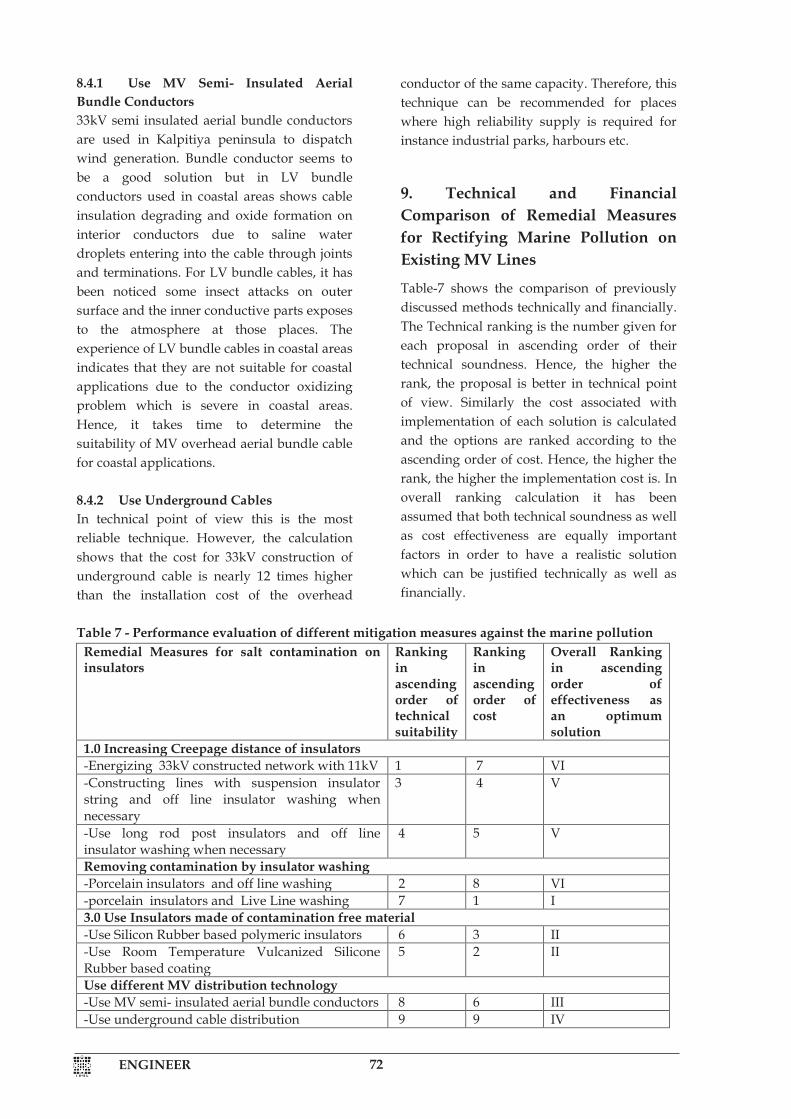
1 ENGINEER
8.4.1 Use MV Semi- Insulated Aerial Bundle Conductors 33kV semi insulated aerial bundle conductors are used in Kalpitiya peninsula to dispatch wind generation. Bundle conductor seems to be a good solution but in LV bundle conductors used in coastal areas shows cable insulation degrading and oxide formation on interior conductors due to saline water droplets entering into the cable through joints and terminations. For LV bundle cables, it has been noticed some insect attacks on outer surface and the inner conductive parts exposes to the atmosphere at those places. The experience of LV bundle cables in coastal areas indicates that they are not suitable for coastal applications due to the conductor oxidizing problem which is severe in coastal areas. Hence, it takes time to determine the suitability of MV overhead aerial bundle cable for coastal applications. 8.4.2 Use Underground Cables In technical point of view this is the most reliable technique. However, the calculation shows that the cost for 33kV construction of underground cable is nearly 12 times higher than the installation cost of the overhead
conductor of the same capacity. Therefore, this technique can be recommended for places where high reliability supply is required for instance industrial parks, harbours etc.
9. Technical and Financial Comparison of Remedial Measures for Rectifying Marine Pollution on Existing MV Lines
Table-7 shows the comparison of previously discussed methods technically and financially. The Technical ranking is the number given for each proposal in ascending order of their technical soundness. Hence, the higher the rank, the proposal is better in technical point of view. Similarly the cost associated with implementation of each solution is calculated and the options are ranked according to the ascending order of cost. Hence, the higher the rank, the higher the implementation cost is. In overall ranking calculation it has been assumed that both technical soundness as well as cost effectiveness are equally important factors in order to have a realistic solution which can be justified technically as well as financially.
Table 7 - Performance evaluation of different mitigation measures against the marine pollution
Remedial Measures for salt contamination on insulators
Ranking in ascending order of technical suitability
Ranking in ascending order of cost
Overall Ranking in ascending order of effectiveness as an optimum solution
1.0 Increasing Creepage distance of insulators -Energizing 33kV constructed network with 11kV 1 7 VI -Constructing lines with suspension insulator string and off line insulator washing when necessary
3 4 V
-Use long rod post insulators and off line insulator washing when necessary
4 5 V
Removing contamination by insulator washing -Porcelain insulators and off line washing 2 8 VI -porcelain insulators and Live Line washing 7 1 I 3.0 Use Insulators made of contamination free material -Use Silicon Rubber based polymeric insulators 6 3 II -Use Room Temperature Vulcanized Silicone Rubber based coating
5 2 II
Use different MV distribution technology -Use MV semi- insulated aerial bundle conductors 8 6 III -Use underground cable distribution 9 9 IV
ENGINEER 72

1 ENGINEER
8.4.1 Use MV Semi- Insulated Aerial Bundle Conductors 33kV semi insulated aerial bundle conductors are used in Kalpitiya peninsula to dispatch wind generation. Bundle conductor seems to be a good solution but in LV bundle conductors used in coastal areas shows cable insulation degrading and oxide formation on interior conductors due to saline water droplets entering into the cable through joints and terminations. For LV bundle cables, it has been noticed some insect attacks on outer surface and the inner conductive parts exposes to the atmosphere at those places. The experience of LV bundle cables in coastal areas indicates that they are not suitable for coastal applications due to the conductor oxidizing problem which is severe in coastal areas. Hence, it takes time to determine the suitability of MV overhead aerial bundle cable for coastal applications. 8.4.2 Use Underground Cables In technical point of view this is the most reliable technique. However, the calculation shows that the cost for 33kV construction of underground cable is nearly 12 times higher than the installation cost of the overhead
conductor of the same capacity. Therefore, this technique can be recommended for places where high reliability supply is required for instance industrial parks, harbours etc.
9. Technical and Financial Comparison of Remedial Measures for Rectifying Marine Pollution on Existing MV Lines
Table-7 shows the comparison of previously discussed methods technically and financially. The Technical ranking is the number given for each proposal in ascending order of their technical soundness. Hence, the higher the rank, the proposal is better in technical point of view. Similarly the cost associated with implementation of each solution is calculated and the options are ranked according to the ascending order of cost. Hence, the higher the rank, the higher the implementation cost is. In overall ranking calculation it has been assumed that both technical soundness as well as cost effectiveness are equally important factors in order to have a realistic solution which can be justified technically as well as financially.
Table 7 - Performance evaluation of different mitigation measures against the marine pollution
Remedial Measures for salt contamination on insulators
Ranking in ascending order of technical suitability
Ranking in ascending order of cost
Overall Ranking in ascending order of effectiveness as an optimum solution
1.0 Increasing Creepage distance of insulators -Energizing 33kV constructed network with 11kV 1 7 VI -Constructing lines with suspension insulator string and off line insulator washing when necessary
3 4 V
-Use long rod post insulators and off line insulator washing when necessary
4 5 V
Removing contamination by insulator washing -Porcelain insulators and off line washing 2 8 VI -porcelain insulators and Live Line washing 7 1 I 3.0 Use Insulators made of contamination free material -Use Silicon Rubber based polymeric insulators 6 3 II -Use Room Temperature Vulcanized Silicone Rubber based coating
5 2 II
Use different MV distribution technology -Use MV semi- insulated aerial bundle conductors 8 6 III -Use underground cable distribution 9 9 IV
1 ENGINEER
10. Conclusions Based on the above analysis the following conclusions can be made. (i) The existing insulator selection criteria
for transmission and distribution overhead power line should be reviewed. New insulator design of coastal line should be introduced and it should be based on the marine pollution information collected at test stations located along the course of the line at particular environment minimally for two years period. Dust gauge technique is recommended to identify the pollution category. Dust gauge measurement can be presented as a pollution map and it will be a valuable guide for future insulator selections.
(ii) For live line insulator wiping technique should be the technically acceptable cost optimized solution for overhead line insulators.
(iii) The performance of Silicone Rubber based RTV coating can be applied on
porcelain insulators but proper evaluation of the losing of hydrophobicity characteristic of different coatings against the tropical climatic condition should be evacuated at least for two years period to select the most appropriate coating.
(iv) Polymer insulators with Silicone Rubber showed better performance than EPDM based insulators as verified by the research conducted in Sri Lanka.
(v) The presently adopting technique of converting 33kV designed network into 11kV to alleviate insulator flashing over in coastal lines cannot be justified in terms of power system planning principles either technically or economically.
(vi) Open type disc insulator profile shows better performance than normal or anti-fog type profiles at coastal applications.
References
1. Fernando, M. A. R. M., Ekanayake, J. B., Wijethilake, A. C. S., Wijerathna, D. C. D. G. and Gubanski, S. M., Recommendations for insulator pollution flashovers in Sri Lanka with special emphasis on a study of composite insulators published in Engineer, journal of IESL, in September 2000.
2. Wijerathna, D. C. D. G., Wijethilake, A. C. S., Ekanayake, J. B., Fernando, M. A. R. M., Composite insulators: performance on the existing pollution problem in Sri Lanka. published in Engineer, journal of IESL transactions volume-1- 1997.
3. IEC 60815(1998) “Guide for selection of insulators in respect of pollution conditions”.
4. IEC 661109 (1992)“ Composite insulators for HV overhead lines with a nominal voltage greater than 1000V –Definitions, test methods and acceptance criteria.
5. IEC 62217(2012) “Polymeric HV insulators for indoor and outdoor use –General Definitions, test methods and acceptance criteria
6. IEEE-std 957-1995 “IEEE Guide for cleaning insulators”.
7. IEC 62073(2003) “Guidance on the measurement
of wettability of insulator surfaces”.
8. 9.
Cherney, E. A., and Corur, R. S., “RTV Silicone rubber coatings for outdoor insulators”, IEEE transactions on Dielectrics and Electrical Insulation, Vol.6, No.5, PP 605-611, 1999. Houlgate, R. G., Swift, D. A., Cimador, A., Pourbaix, F., Marrone, G., Nicolini, P., “Field experience and laboratory research on composite insulators on overhed lines”,Cigre, paper no. 12-12,1986.
ENGINEER73