Embed Size (px)
Citation preview

© 2015 ISIJ 36
Review
ISIJ International, Vol. 55 (2015), No. 1, pp. 36–66
Steelmaking Technology for the Last 100 Years: Toward Highly Efficient Mass Production Systems for High Quality Steels
Toshihiko EMI*
Formerly Tohoku University and Kawasaki Steel. Now at Takaido Higashi 1-31-6-603, Suginami, Tokyo, 168-0072 Japan.
(Received on August 15, 2014; accepted on September 29, 2014; originally published in Tetsu-to-Hagané,Vol. 100, 2014, No. 1, pp. 31–58)
Progress of steelmaking technology in Japan over the last 100 years is overviewed covering hot metalpretreatment, primary steelmaking with open hearth furnaces, converters and electric arc furnaces, sec-ondary refining of steel with degassers and ladle furnaces, and ingot- and continuous-casting.
Key issues that contributed considerably to the progress of the unit processes are highlighted with sci-entific, technological and engineering breakthroughs involved. Also, systematization of the unit processesis depicted for optimizing full cost, productivity and quality of steel products to meet the constraints onthe resources and socioeconomic demands of the steel market at times.
Possible future development of steel technology is briefly commented on the basis of the above obser-vation.
KEY WORDS: Historical overview; hot metal pretreatment; primary- and secondary-steelmaking; ingot- andcontinuous-casting; steelmaking system.
1. Introduction
Celebrating the centennial anniversary of the Iron andSteel Institute of Japan, an attempt is made to give an over-view of the development of steelmaking technologies inJapan in the last 100 years with own limited experiences inthe field of 55 years and available literatures. The technol-ogies cover hot metal pretreatment, primary- and secondary-steelmaking and ingot- and continuous-casting, which wereimproved and optimized for materials and market availableat times by the lasting efforts of our predecessors. The over-view is intended to give a concise but panoramic under-standing of the past developments and stimulate the cominggeneration to further revolutionary technological advancefor the future development of the steel industry.
2. Open Hearth Steelmaking1–9,12)
2.1. From Crucible Furnace and Bessemer Converterto the Golden Days of Open Hearth
Steelmaking furnaces so far industrialized in the worldwere: Converter with acidic refractory lining and air blow-ing bottom tuyeres in 1856, Siemens open hearth in 1857,and Martin furnace for scrap melting, and Siemens-Martinopen hearth which combined the last two in 1864. It took,however, about 20 years more, when the converter and openhearth, both lined with basic refractory, successfullydephosphorized hot metal for mass production of steel withacceptable quality. Hot metal in Europe was high in phos-
phorus (P) since iron ore available there was high in P.Mass production of steel in those days was dominated by
Britain, Germany, Belgium and USA. Japan imported nec-essary pieces of equipment, materials, operational skill, andraw materials from these countries to start industrial steel-making with crucible furnace in 1890. Acidic open hearthand acidic Siemens-Martin open hearth were installed in1890 and 1896 at navy- and army-steelmaking factory.Annual production of the factories was a small sum of 2.4k tons, only about 1.1% of annual steel imports of 220 ktons.
Integrated iron and steel plant ever started in Japan wasin 1901 at state-owned Yawata Works.1–4) A 160 ton blastfurnace (BF) was put into operation in Feb., and steel meltfrom a 25 ton open hearth was cast into 3 ingots in total of10 tons in May. In November, steel melt from a 15.6 m3
Bessemer converter was cast into 5 ingots, totaling 8.5 tons.Japanese naming for open hearth, Heiro, and converter, Ten-ro, was given by Imaizumi.5)
After the end of the Russo-Japanese War in 1905 until theoutbreak of World War I in 1914, Japanese steel industrysuffered from a recession, facing plant shutdowns and merg-ers. Inadequacy of equipment for operation and lack ofdecent quality coal and iron ore were considerable. Despitethe unfavorable circumstances, efforts paid by YawataWorks made it possible in 1914, 100 years ago, to convertsteel ingot production from remelting and casting iron madewith traditional charcoal based Tatara process (17 ktons/year)to casting steel made with Basic Open Hearth (BOH) (275ktons/year) and acidic Bessemer converter (106 ktons/year).
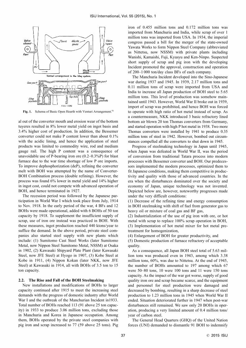
Productivity of the acidic Bessemer converter was muchgreater than the BOH (Fig. 1),6) but the slopping loss of met-
* Corresponding author: E-mail: [email protected]: http://dx.doi.org/10.2355/isijinternational.55.36
ISIJ International, Vol. 55 (2015), No. 1
37 © 2015 ISIJ
al out of the converter mouth and erosion wear of the bottomtuyeres resulted in 8% lower metal yield on ingot basis and3.4% higher cost of production. In addition, the Bessemerconverter could not make P content lower than about 0.1%with the acidic lining, and hence the application of steelproducts was limited to commodity wire, rod and mediumgauge rail. The high P content was a consequence ofunavoidable use of P-bearing iron ore (0.2–0.3%P) for blastfurnace due to the war time shortage of low P ore imports.To improve dephosphorization (deP), refining the convertermelt with BOH was attempted by the name of Converter-BOH Combination process (double refining). However, theprocess was found 6% lower in metal yield and 14% higherin ingot cost, could not compete with advanced operation ofBOH, and hence terminated in 1927.
The recession period was followed by the Japanese par-ticipation in World War I which took place from July, 1914to Nov. 1918. In the early period of the war, 4 BFs and 12BOHs were made operational, added with 6 BOHs of 50 toncapacity by 1918. To supplement the insufficient supply ofscrap, use of iron ore instead was practiced in BOH. Withthese measures, ingot production reached 440 ktons/year tosuffice the demand. In the above period, private steel com-panies also started steel supply with new plants whichinclude: (1) Sumitomo Cast Steel Works (later SumitomoMetal, now Nippon Steel Sumitomo Metal, NSSM) at Osakain 1902, (2) Kawasaki Shipyard Plate Plant (later KawasakiSteel, now JFE Steel) at Hyogo in 1907, (3) Kobe Steel atKobe in 1911, (4) Nippon Kokan (later NKK, now JFESteel) at Kawasaki in 1914, all with BOHs of 3.5 ton to 15ton capacity.
2.2. The Rise and Fall of the BOH SteelmakingNew installations and modifications of BOHs to larger
capacity continued after 1915 to meet the increasing steeldemands with the progress of domestic industry after WorldWar I and the outbreak of the Manchurian Incident in1933.Total number of BOHs reached 113 (91 above 25 ton capac-ity) in 1933 to produce 3.06 million tons, excluding thosein Manchuria and Korea in Japanese occupation. Amongthem, BOHs operated by the private steel companies withpig iron and scrap increased to 77 (59 above 25 tons). Pig
iron of 0.455 million tons and 0.172 million tons wasimported from Manchuria and India, while scrap of over 1million tons was imported from USA. In 1934, the imperialcongress passed a bill for the merger of the state-ownedYawata Works to form Nippon Steel Company (abbreviatedas Nittetsu, now NSSM) with private plants includingWanishi, Kamaishi, Fuji, Kyusyu and Ken-Ninpo. Suspectedshort supply of scrap and pig iron with the developingIncident promoted the approval, construction and operationof 200–1 000 ton/day class BFs of each company.
The Manchuria Incident developed into the Sino-Japanesewar during 1937 and 1945. In 1939, 2.17 million tons and0.11 million tons of scrap were imported from USA andIndia to increase all Japan production of BOH steel to 5.65million tons. This level of production was somehow main-tained until 1943. However, World War II broke out in 1939,import of scrap was prohibited, and hence BOH was forcedto operate with high ratio of hot metal instead of scrap. Asa countermeasure, NKK introduced 3 basic refractory linedbottom air blown 20 ton Thomas converters from Germany,and started operation with high P hot metal in 1938. Two moreThomas converters were installed by 1941 to produce 0.35million tons of steel in 1942. However, bombed out circum-stances compelled all the converters to shut down in 1945.
Progress of steelmaking technology in Japan until 1945,when Japan was defeated in World War II, was the periodof conversion from traditional Tatara process into modernprocesses with Bessemer converter and BOH. Our predeces-sors implemented the modern processes, optimized them tofit Japanese conditions, making them competitive in produc-tivity and quality with those of advanced countries. In theera when the disturbances dominated over the society andeconomy of Japan, unique technology was not invented.Depicted below are, however, noteworthy progresses madeunder the very difficult conditions:(1) Decrease of the refining time and energy consumptionin BOH steelmaking with shift of fuel from generator gas toheavy oil or mixture of coal gas and BF gas,(2) Industrialization of the use of pig iron with ore, or hotmetal with scrap to replace 100% scrap operation in BOH,(3) Implementation of hot metal mixer for hot metal pre-treatment for homogenization,(4) Enlargement of BOH for greater productivity, and(5) Domestic production of furnace refractory of acceptablequality.
As a consequence, all Japan BOH steel total of 5.63 mil-lion tons was produced even in 1943, among which 3.38million tons, 60%, was due to Nittetsu. At the end of 1945,the number of BOHs amounted to 197 among which 67were 50–80 tons, 10 were 100 tons and 11 were 150 tonscapacity. As the impact of the war got worse, supply of goodquality iron ore and scrap became scarce, and the equipmentand personnel for steel production were damaged anddecreased by bombing, resulting in a sharp decrease of steelproduction to 1.23 million tons in 1945 when World War IIended. Situation deteriorated further in 1947 when post-wardisturbances still remained. We saw only 20 BOHs in oper-ation, producing a very limited amount of 0.4 million tons/year of carbon steel.
The General Head Quarters (GHQ) of the United Nationforces (UNf) demanded to dismantle 91 BOH to indemnify
Fig. 1. Schema of Basic Open Hearth with Venturi Arrangement.6)

© 2015 ISIJ 38
ISIJ International, Vol. 55 (2015), No. 1
in kind UNf for war damage. Fortunately, it was soon with-drawn to promote economic self-reliance of Japan and meetthe need of GHQ to supply materials to support UNf for theKorean war which lasted during 1950 and 1953. Thus, steelindustry in Japan was made exempt from crashing down.Increase of steel production started, followed by the removalin 1948 of embargo on the import of iron ore and coal.
2.3. Enlargement of BOH after World War II andDevelopment of Oxygen Steelmaking7–9,12)
German type BOHs were dominantly utilized in Japan inthe war time. During 1948 and 1949 after World War II,equipment and operation of USA type BOHs, which weresuperior to German type, were introduced to Japan by USAspecialists. Delegation to implement the BOH technologywas also sent to USA for training. Consequent improve-ments transferred were:(1) Enlargement of stationary hearth BOH with hung downrefractory ceiling structure,(2) Movable down-spout for tapping, and jet tapper,(3) Venturi combustion system with enlarged gas port, gasuptake, and checker brickwork in recuperater chambers,(4) Blaw-knox type valve to change gas flow,(5) Quick charging of scrap box,(6) Positive pressure operation of BOH to prevent the intakeof ambient air,(7) Conversion of generator gas or mixed gas combustion toheavy oil combustion due to the removal of oil embargo,(8) Utilization of sensor controlled operation with pressuregauge, gas flow meter and thermometer,(9) Use of basic refractory bricks for the front- and rear-walland the ceiling of BOH, and(10) Magnesia stamping and dolomite gunning on thehearth.
During 1949 and 1957, average capacity per heat ofBOHs increased from 62 tons to 92 tons, maximum nominalcapacity being 150 tons. In 1957, the number of BOHs withheavy oil combustion or heavy oil mixed combustionreached 115 out of 124. In the following 5 years, BOHcapacity kept increasing. Within the major 4 companies,Yawata, Fuji, NKK and Kawasaki, for example, 4 × 150 tonMärtz/Märtz Böhrens* type stationary- and tilting-BOHswith Venturi combustion system and 3 × 200 ton BOHswere installed together with revamped 9 × 150 ton BOHsand 11 × 200 ton BOHs (*Note: All basic refractory brickstructure with checker brickwork type No.1 chamber andordinary type No.2 chamber. First put into operation atSumitomo Metal Wakayama Works in 1959).
Also, oxygen injection steelmaking process, which waspopular in USA, was introduced after joint industrial testscarried out by 8 domestic companies. This was in collabo-ration with the installation of Linde-Frenkel type mass pro-duction system for pure oxygen. The oxygen steelmakingprocess12) utilized oxygen for:(1) Enhancing the combustion of fuel from burner,(2) Cutting the scrap debris before melting down, and(3) Bessemerizing of steel melt after the melt down.These measures considerably improved the productivity andfuel consumption of BOH.
In fact, the peak production of steel with BOH oxygensteelmaking in Japan recorded a high 16.17 million tons in
1961. At Fuji iron and Steel (now Nippon Steel SumitomoMetal, NSSM) Hirohata Works, scrap 210 tons were over-charged in a 150 ton BOH, converted into steel in 6 h (pro-ductivity 33 tons/h) with 25 Nm3O2 at a fuel consumptionof 1 420 kJ/ton, much better than 12 h (16 tons/h) and 4 180kJ/ton for normal operation. Similarly, at Kawasaki Steel(now JFE Steel) Chiba Works, scrap 185 tons were over-charged in a 150 ton BOH, and converted into steel withlarge supply of oxygen in 2 h 40 min. With 6 of the BOHand oxygen supplied from Linde-Frenkel oxygen generatorsin total of 13 400 Nm3/h, average productivity of steelachieved 65 tons/h/BOH. Maximum productivity surged to100 tons/h/BOH when maximum oxygen supply of 50Nm3O2/ton was executed. Chiba with the 6 BOHs countedthe highest production record of 180 ktons/mo. as a singleBOH plant in Japan.
Bessemerizing (oxygen injection) was made via calorizedsteel tube inserted in steel bath in BOH through a view portat the charging doors of BOH. It was quite an experience ofthe author to watch the surface of the bath while pushing theconsumable pipe into the bath on shoulder as it melted awayduring the Bessemerizing. As bath temperature rose withtime, decarburization and refining proceeded with carbonboil. Top slag on the bath was mixed up with metal on vig-orous break up of CO bubbles. When compared with chem-ical analysis report of samples taken from time to time, theauthor realized how decarburization and refining went on. Itwas a marvelous moment of on site and real time observa-tion of metallurgy of steelmaking.
3. Steelmaking with Oxygen Top Blown Converter9–13)
3.1. Evolution of Oxygen Top Blown LD ConverterSteelmaking
Oxygen top blown Linz Donawitz converter (LD) startedits operation at Vöest Linz with 3 × 30 t vessels in 1952 andat ÖMAG (Alpine) Donawitz with 2 × 30 t vessels, all withBOH hot metal. In Europe, Thomas converter process wasin operation with high P hot metal smelted from Europeaniron ores with high P content. However, such P-bearing ironores were not available in Austria where only low P hot met-al was produced. Low P hot metal was insufficient to sustainheat balance in Thomas converter. In addition, demands forsteels low in P and N were uprising to guarantee better coldformability. Thomas converter steel was difficult to meetsuch demands. Attempts were made to decrease N in theconverter steel with oxygen enriched air blow, but not suc-cessful due to heavy tuyere erosion. Scrap supply was insuf-ficient in Austria to sustain BOH operation despite the factthat BOH steel lower in P and N is better in cold formability.
To solve the problems, Dürrer and colleagues carried outexperiments with pure oxygen blown from water cooled toplance to the steel melt surface with success. Vöest andÖMAG adopted the technology, went into joint develop-ment, and succeeded to operate 2 ton vessel, subsequently12–15 ton vessels in 1949, making the contents of P, N andO reduced below BOH steel.
3.2. Transfer of LD Steelmaking Process to Japan10–12)
Regarding pneumatic converter operation in Japan, Yawatahad operational experiences of Bessemer converter which

ISIJ International, Vol. 55 (2015), No. 1
39 © 2015 ISIJ
lasted until 1927 and of 5 ton top blown converter since1954. NKK revitalized basic Thomas converter operation in1954 with oxygen enriched air blow. The two companieshad an exposure to the information on the LD operation inAustria via Ministry of International Trade and Industry(MITI) and a trading company of Japan. They were stimu-lated by the operational advantages over Thomas converteror BOH of LD that fits low P hot metal, lower scrap ratio,lower refractory consumption, and needed no heavy oil asfuel. Also, productivity, installation cost, labor cost, operat-ing cost and steel quality of LD were speculated better thanThomas converter or BOH, although the process technologywas still in its infancy of industrial mass production.
The two companies sent separately their representativesto confirm the speculation on sites, believed the futurepotential of LD process, and attempted to negotiate indepen-dently with Alpine to introduce LD technology. In view ofnational interest, however, they accepted, under the auspicesof MITI, to let NKK as the sole representative licensee ofthe use and granting in Japan of the technology. Accordingly,the licensee contract was struck between NKK and BrassertOxygen Technik AG (BOT, licensing company) via Alpinein 1956. Yawata struck with NKK sub-licensee contractwhich has been kept open for domestic third parties. Instal-lation and operation of 50 ton LD at Yawata and 42 ton LDat NKK started soon in 1957 and 1958, as the milestone inthe history of LD steelmaking in Japan.
The aforementioned advantages combined with financialsupport by MITI on the second rationalization program ofJapanese steel industry prompted other steel companies toinstall LD converters (Fig. 2,16) upper left). The share of LDsteel production started around 5% in 1958, surpassed BOHsteel share in 1965 to reach 55%, and achieved in 1970 ahigh 79% with a production of 73.51 million tons, top in theworld. New installations of LDs and conversion of BOHs toLDs, and revamping and merger of obsolete LDs to buildnew LDs continued until 1973, just before the oil shock cri-
sis. It was the time when we saw a total of 92 LDs including11 × 250 ton vessels and 6 × 300–340 ton vessels kept theleading position in both the amount and share of LD steelproduction in the world, exceeding West Germany, USA,Britain and USSR.
In contrast, BOH steel production declined sharply. In1970, BOHs in major steel companies were all shut down,leaving only 1.99 million tons produced in 1971 in Japan.Last BOH was shut down at Tokyo Steel Okayama worksin 1977, closing long glorious history.
3.3. Development of LD Steelmaking Process inJapan12–14)
The prosperity of LD process was brought about by suchadvantages as a few times greater productivity, lower pro-duction cost (~10% for carbon steel, ~30% for HSLA steel)and lower need of scrap than BOH process. The advantageswere materialized due to the following improvements anddevelopments in equipment and operation elaborated afterthe LD technology transfer:(1) Enlargement of the shell volume, supporting and tiltingmechanism for the vessel with concentric tulip profile andtaphole, eliminating detachable bottom. For a 300 ton ves-sel, inner steel shell volume and height/diameter ratio wereset, for example, to be 553 m3 and 1.3. Top cone angle wasoptimized, and trunion ring support and stepless variablespeed tilting system were selected,(2) Water cooled main lance with multiple hole nozzle tipwas invented to prevent spitting and bottom refractory ero-sion during the blow (1962–1970),(3) Automatic exchange system of sub-lance, equipped withtemperature sensor and carbon meter, was made fully oper-ational (1966–),(4) Non combustive off-gas recovery system (OG) wasdeveloped by Nippon Steel (now Nippon Steel SumitomoMetal, NSSM) to retain off-gas energy and minimize off-gasvolume and particulate emission (1962–1969). The systemhas been upgraded and popularly accepted in the world,(5) Considerable reduction of vessel refractory consumptionto ~7 kg/ton-steel with the development of tar bonded dolo-mite, stabilized dolomite bricks followed by magnesia car-bon bricks,(6) Significant improvement of the hit rate of carbon contentand temperature (C-T) window at the blow end wasachieved with a static and dynamic computer control of themain lance height and oxygen flow rate, utilizing accumu-lated blow data calibrated with C-T values measured ontime with the sub-lance,(7) Production of hot metal low in Si and P for LD by useof advanced operation of BF with low P iron ores importedfrom Brazil and Australia, accompanied by decreased returnof P-bearing BOH slag to BF,(8) Development and implementation of hot metal pretreat-ment process and secondary refining process prior to andafter the LD blowing,(9) Advance of single slag and catch carbon blowing tech-nique for medium and high carbon steels, low alloy steelsand stainless steels to the extent that the resulting steel qual-ity was approved by the standards in JIS specifications,(10) Prolongation of vessel life beyond 5 000 heats/cam-paign by developing zone lining of refractory, hot gunning
Fig. 2. LD (BOF), Mixed Blowing BOFs and Bottom Blown BOF(Q-BOP)16) (partly modified).

© 2015 ISIJ 40
ISIJ International, Vol. 55 (2015), No. 1
refractory repair technology and enrichment of magnesia inLD slag during the blow, resulting in increased LD productiv-ity,(11) Progress in (a) Measurements at elevated temperaturesof thermodynamic quantities and physical properties of thematerials relevant to the process, (b) Equilibrium calculationfor steelmaking reactions, (c) Modeling of heat, mass andenergy transport phenomena for the process analysis, (d)Fluid dynamic simulation of the process, and(12) Development of the theory and system for the controland automation of the process.
Many of the above depended on the progress achieved inEurope and USA. Among them, however, original develop-ment and industrialization progressed in Japan were items(2) and (4), and considerable progresses achieved in Japanafter they were originally introduced from abroad wereitems (5) through (12). Cooperation among the licenseecompanies to share relevant information on timely techno-logical advances at the meetings and plant visits of LD com-mittee (later Discussion Meetings for Japan LD Technology)promoted by NKK and Yawata for Japan BOT members(1958–1966), contributed greatly to the progresses. Themeetings were succeeded by the Steelmaking division ofJoint Study committee of the Iron and Steel Institute of Japan(ISIJ). Also, joint activities among academia and industryheld by the Joint Study committee for the Fundamentals ofIron and Steel, by Melt Refining division and by bi-annualMeetings, all held under the auspices of ISIJ, and those heldby 19th committee (1934–) of the Japan Society for Promot-ing the Science (JSPS), all enhanced the progresses greatly.It must also be noted that these activities were supported bythe Japan Iron and Steel Federation (JISF) and MITI eitherdirectly or indirectly.
3.4. Maturation of LD Process for High ProductivityLD operation continued to proceed toward higher produc-
tivity with extended flexibility for hot metal ratio underfavorable economy which prevailed after 1967. Notabletechnologies that supported maturation of LD for higherproductivity were:(1) Charge time reduction with large capacity torpedo/ladlecar to transport hot metal to steelmaking shop, and the samewith scrap loading in charging shoot in separate building,(2) Thinner refractory lining to enlarge the inner volume ofthe vessel with developed magnesia-carbon brick,(3) Hot gunning of magnesia or dolomite with vessel profilemonitoring, and slag coating, both to cutback the repair timeand prolong service life of the vessel refractory,(4) Computer control of the main lance height and oxygenflow rate, and optimization of the multiple hole lance tipdesign, both to minimize slopping and enhance deP undermuch increased oxygen flow rate,(5) Three vessels operation out of 3 vessels installation,(6) Development of “Direct tapping” which eliminated thetime consuming end point sub-lance measurement of C andT, as the ultimate in dynamic blow control.
Consequently, average productivity of LDs reached 240tons/h in 1974 with the improved equipment and operation.End point hit rate for C-T window in many LD plantsachieved about 90% for low C steels, although scrap ratewas limited. Vessel refractory life was very much pro-
longed, record being 10 110 heats/campaign established atNippon Steel (now NSSM) Kimitsu Works.
Noteworthy progress of LD process since then has beenfurther prolonged vessel refractory life with slag splashingpractice developed in USA.16) After tapping, dolomite isadded to remaining slag on the bottom of the vessel, mainlance is lowered some 70 cm above the bottom, and themagnesia enriched molten slag at the bottom is splashedwith nitrogen gas blown from the main lance to weld coatthe inner surface of the vessel refractory. No particularequipment is necessary, operation is simple, lasting within ashort period of time to proceed to the subsequent blow, andhence the splashing technique soon has become popularworldwide. Refractory life from fresh lining to the 1st relin-ing exceeded some 20 000 heats. In the slag splash coatingpractice, however, clogging of tuyeres installed at the bot-tom of mixed blown converters (see later) was worriedabout in the beginning. It was resolved by controlling bottomgas flow rate at the nitrogen gas flushing. Recentpresentation17) reportedly said that delivery of inert gasthrough concentric bottom tuyeres combined with propergas flushing program made the refractory life extended upto 50 000 heats/campaign. Caution is, however, necessary tokeep reasonable trade off, i.e., not to worsen proper blowcharacteristics in the vessel with off-design distorted innerprofile which may result from too many times of the splash-ing.
Regarding the automatic blow operation, the C-T hit ratewas made better for narrower target window. Trimming theblow pattern was refined for reduced spitting and sloppingwith amended material addition. These were made possibleon the basis of integrated computer analysis of the dataacquired with sensors for the volume and composition of off-gas, temperature and compositions of the steel melt, vibrationof the vessel, and acoustic wave characteristics in the vessel.
4. Steelmaking with Bottom Blowing and Mixed Blow-ing Converter18–20)
4.1. Birth of Bottom Blowing Converter, OBM/Q-BOPExcept for its own advantages mentioned above, LD
exhibited some drawbacks, i.e.,(1) Insufficient mixing of metal bath, resulting in heteroge-neity in temperature and chemistry of the bath,(2) Sluggish molten slag formation of added lime,(3) Loss of iron caused by excessively high temperature andover oxidation at the impinging points of oxygen jet on themetal bath, and(4) Difficulty to prevent the slopping when abrupt CO bub-ble evolution occurred due to the over oxidation and hetero-geneity of carbon distribution in the bath. The multiple holelance tip was to some extent effective to reduce the sloppingby decreasing the heterogeneity, but not fully. The sloppinghappens when the bubbles in the molten slag do not breakup easily and retained in the slag under unfavorable combi-nation of temperature and the bubble breakability of the slagwhen deC rate is high.
Thomas converter could avoid the heterogeneity andhence the slopping. As mentioned before, however, it couldnot take up more than 40% oxygen in the blowing gas dueto the serious incidence of the tuyere erosion. Savard and

ISIJ International, Vol. 55 (2015), No. 1
41 © 2015 ISIJ
Lee20) of Canadian Liquid Air overcame the erosion prob-lem with a new idea to employ concentric double tube tuy-eres after many difficult trials. Hydrocarbon gases (propane,methane) were passed through outer slit of the concentrictuyere tube as a coolant which endothermically decomposedto cool the tip of the tube. Oxygen gas and lime powderwere injected through the inner tube into the melt. A porousaccretion called “mushroom” was formed on the tip whichprevented direct contact of steel melt to the tip, and cooldecomposed gas was allowed to pass through the pores.21)
Brotzmann of Maxhütte decided to replace the tuyereswith the concentric ones at 20 ton Thomas converter ofMaxhütte, made trials in 1967, and succeeded in the indus-trialization in 1968 by the name of Oxygen Bottom BlownMaxhütte (OBM). Later, US Steel implemented the OBM inlarge scale at Gary works 200 ton basic oxygen furnace(BOF, same as LD, but claimed to be USA origin) in 1973and at Fairfield works 160 ton BOFs in 1974, by the nameof Q-BOP which stands for Quick refining, Quiet blowing,Quality Basic Oxygen Process.
Major problem encountered with Q-BOP was poor endur-ance of the bottom tuyeres. It was necessary to keep themushroom accretion on all tuyeres in similar size for longlife of the tuyere bottom. If imbalance in the cooling hap-pened to let a mushroom melt away, the tip of the tuyereburned back excessively to damage the bottom. In anextreme case, the burn back proceeded to the outer side ofthe bottom, caused back fire to burn through the tuyere, andburned the connecting oxygen gas piping, resulting in steelmelt leakage out of the vessel.
4.2. Blowing Characteristics of Q-BOP18)
In Japan, Kawasaki Steel introduced Q-BOPs in 1977 tobuild two 230 ton Q-BOPs with 18 and 22 tuyere bottomsat Chiba (Fig. 2, upper right).16) Parameters to control theblowing process were established through extensive inves-tigation with a water model and a 5 ton Q-BOP for the meltflow in the vessel, mode of lime injection, characteristics ofsteelmaking reactions, and wear of refractory.
Q-BOP is distinctly different from LD as follows due tothe full injection of oxygen gas and lime powder from thebottom tuyeres:(1) Quick remelting of charged scrap,(2) Very fast homogenization of steel melt is sustained tolow C range. In terms of the time required for uniform mix-ing of the melt, Q-BOP takes only about 10% of that for LD(Fig. 3),23)
(3) The rate of decarburization (deC) is also very fast, pro-ceeding in near equilibrium for C-O reaction,(4) Loss of Fe and Mn in slag caused by over oxidation issmaller, and hence yield of Fe and Mn is higher. For exam-ple, total Fe content in slag (T.Fe) at 1 630°C and 0.04%Cis ~12% against ~23% for LD,(5) Oxgen consumption for Q-BOP is lower, accordingly.Decarburization oxygen efficiency for LD decreases fromunity at 0.8%C down to 0.6 at 0.2%C, whereas for Q-BOP,it keeps unity until 0.4%C and decreases to 0.9 at 0.2%C.Decarburization limit of Q-BOP is lower than LD, can beless than 0.02%C,(6) Slag formation is quicker, over oxidation and slagamount are much smaller, and hence sample taken with sub-
lance represents C and T of the melt bulk better. Conse-quently, the hit rate at blow end reaches near 99% andreblow rate less than 1% for a target window of 0.05 ±0.015%C and 1 610 ± 10°C at 10% scrap operation,(7) Slopping is much decreased and off-gas recovery withOG reaches 1.4 GJ/ton,(8) Desulfurization (deS) ratio is better, and deP ratio is notmuch different from LD despite lower (T.Fe), provided thatsplit injection of lime in the initial period and later periodof blowing is properly executed.
On the other hand, inherent disadvantages of Q-BOP are:(1) Higher cost of investment,(2) Refractory life of the tuyere bottom is still shorter thanthat of the vessel, calling for 2–3 times of the bottomexchanges during a campaign of the vessel refractory,(3) Scrap charge ratio becomes less to the extent equivalentto the heat loss caused by the coolant gas usage,(4) Blow end hydrogen content in Q-BOP melt, even afterAr flushing, is higher (4–7 ppm) than LD melt (2–3 ppm)due to the hydrogen input generated by the decompositionof the hydrocarbon coolant. In modern steelmaking systemwhere vacuum degassing is commonly equipped, this maynot be a serious issue, though.
As a similar process to Q-BOP, kerosene coolant wasused instead of hydrocarbon gases in 240 ton LWS converterat Sollac in 1978.
The above mentioned blowing characteristics were semi-empirically well explained by Nakanishi et al.23) in terms ofan Index for Selective Carbon Oxidation (ISCO) based onmodel study and on site operation data. The ISCO consistsof the product of two terms;(1) Thermodynamic term stands for the partial pressure of COwhich defines C-O equilibrium on the melt bath surface, and(2) Relative mass transfer term represents the ratio of massflux of oxygen supplied from the bottom tuyeres (or mainlance) to the gas/melt boundary to the mass flux of C sup-plied from the melt bath to the boundary. Here, the massflux of C was approximated by the average melt flow rate,q, in the bath, and q was defined proportional to the inverseof uniform mixing time, τ , of the melt (q = 1/τ). τ was deter-mined proportional to about –0.4 power of the mixing energy,ε , supplied to the bath (τ ∝ε–0.4). Term (2) shows the pre-
Fig. 3. Mixing Time of Melt in Various BOFs vs. Bottom GasFlow Rate.23)

© 2015 ISIJ 42
ISIJ International, Vol. 55 (2015), No. 1
dominance of either the oxidation of Fe or the oxidation ofC of the melt under a given CO pressure. The smaller theISCO value, the better is the preferential deC to lower Crange without much loss of Fe into top slag.
The ISCO value successfully described the first time in anintegrated way the relation between the degree of melt stir-ring and the oxidation into slag of constituent elements inthe metal bath for a variety of primary and secondary refin-ing furnaces (Figs. 3 and 4, for example),18,23) and consid-ered to be a great contribution to process metallurgy. Later,Kai et al.24) proposed an amended index, Balance of Oxygenand Carbon Feeding Rate (BOC), eliminating term (1) andreplacing the metal flow rate in term (2) in ISCO with massflux of C. BOC was reported to give a bit better correlationin describing the behavior of (T.Fe) than ISCO within arange of 0.02–0.22%C for LD.
4.3. Development of Q-BOP Toward Mixed BlowingConverters
A mixed blowing form between LD and Q-BOP, with 70%oxygen blown from top lance and 30% oxygen injected frombottom tuyeres, has been put into operation at Mizushima (3 ×250 tons) and Chiba (2 × 85 tons) during 1980–1981. Thetop and bottom blowing converter was named K-BOP(Kawatetsu-BOP where the prefix means Kawasaki Steel inJapanese, Fig. 2 bottom center). The ISCO value for the K-BOP is determined to be 64, close to 58 for the Q-BOP, andmuch smaller than about 230 for 160 ton LD, despite the lim-ited fraction of oxygen bottom injection. K-BOP exclusivelyblows oxygen from top and bottom until critical C of 0.10–0.15% is reached, followed by inert gas bottom injection topromote deC in the range below the critical C (called Inert gasDecarburization, ID). It is capable of changing the main lanceheight to prevent slopping, acquiring better freedom to formslag and better control of deP operation.
Similar mixed blowing or top and bottom blowing LDwith the bottom blowing through the concentric tuyeres,called LD-OB (LD-Oxygen Bottom Blowing) has also beenindustrialized in total of 10 at Nippon Steel Yawata, Oita,Kimitsu and Nagoya in 1984. Total number of the top blow-ing converters with oxygen bottom blowing (OBM, Q-BOP,K-BOP, LD-OB etc,, all inclusive) amounts to 110 in theworld. Sumitomo Metal (now NSSM) industrialized a top andbottom blowing, STB (Sumitomo Top and Bottom), with CO2
as bottom tuyere coolant in place of hydrocarbon gases.It was known in Thomas converter and secondary refin-
ing furnace that bottom injection of gases promotes the stir-ring and flow of steel melt. However, the considerableimprovement of blowing characteristics for LD with theoxygen bottom injection was a fresh surprise to those whowere engaged in steelmaking, triggering off the evolution ofa variety of top and bottom blowing converters.
As noted before, uniform mixing time, τ , is inversely pro-portional to 0.4 power of energy ε of stirring imposed anddissipated in the melt. Average flow rate q (ton/s) of the meltis inversely proportional to τ, i.e., q = 2 W/τ , with W (ton)being the mass of steel melt.
For an inert gas bottom stirring 250 ton LD (LD-KGC) atMizushima, τ is calculated to be 37 s at a small 10% bottominjection of Ar, much shorter than about 75 s for LD withoutthe bottom injection, and not too much longer than 14 s forQ-BOP at Chiba. Concentration product of C and O in themelt in mixed blowing converters is found to decreasebelow the equilibrium concentration product of Ceq andOeq at a shorter τ. In former times, this anomaly was inter-preted to have been caused by lower partial pressure of COthan unity in the converters due to decomposed hydrocarboncoolant. Kishimoto et al.26) showed, however, that O contentin the melt did not change with the species of hydrocarboncoolant, but decreased with increased q (= shorter τ). Theyconsidered that the anomaly is caused by the following: Atthe impinging points of oxygen jet on the steel melt, theactivity of (FetO) formed by the oxidation of the melt isunity and O in the melt may come close to the equilibriumvalue corresponding to C and T around there. When meltstirring or melt flow rate is large enough, however, O in thebulk melt should be dominated with (FetO) which is gener-ated at the impinging points but diluted in slag which coversmuch wider surface area of the melt than the area of firespots. The stronger the stirring or the greater the flow rate,the lower the (FetO) which dominates the O in the melt, andhence O decreases with q.
4.4. Wide Spreading Development of LD with BottomInjection of Inert Gases
In view of the considerable improvement of blowingcharacteristics of LD with a small amount of inert gas injec-tion from the bottom, the inert gas injection soon replacedoxygen and lime injection from the concentric tuyeres toeliminate the exchangeable bottom with the tuyeres andreduce the necessary investment and running cost.
The following type LDs with gas stirring have been
Fig. 4. Oxidation of Iron in Slag in Various BOFs vs. Mixing Time or ISCO.18,23)
ISIJ International, Vol. 55 (2015), No. 1
43 © 2015 ISIJ
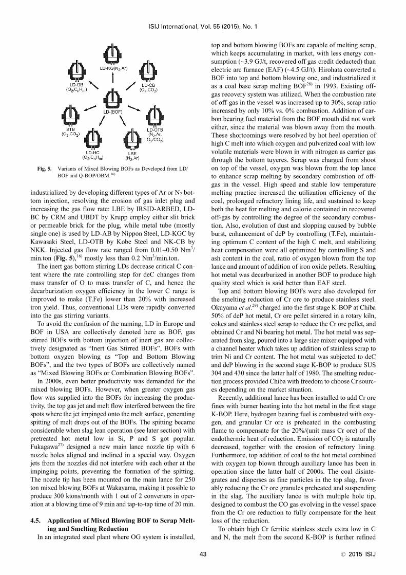
industrialized by developing different types of Ar or N2 bot-tom injection, resolving the erosion of gas inlet plug andincreasing the gas flow rate: LBE by IRSID-ARBED, LD-BC by CRM and UBDT by Krupp employ either slit brickor permeable brick for the plug, while metal tube (mostlysingle one) is used by LD-AB by Nippon Steel, LD-KGC byKawasaki Steel, LD-OTB by Kobe Steel and NK-CB byNKK. Injected gas flow rate ranged from 0.01–0.50 Nm3/min.ton (Fig. 5),16) mostly less than 0.2 Nm3/min.ton.
The inert gas bottom stirring LDs decrease critical C con-tent where the rate controlling step for deC changes frommass transfer of O to mass transfer of C, and hence thedecarburization oxygen efficiency in the lower C range isimproved to make (T.Fe) lower than 20% with increasediron yield. Thus, conventional LDs were rapidly convertedinto the gas stirring variants.
To avoid the confusion of the naming, LD in Europe andBOF in USA are collectively denoted here as BOF, gasstirred BOFs with bottom injection of inert gas are collec-tively designated as “Inert Gas Stirred BOFs”, BOFs withbottom oxygen blowing as “Top and Bottom BlowingBOFs”, and the two types of BOFs are collectively namedas “Mixed Blowing BOFs or Combination Blowing BOFs”.
In 2000s, even better productivity was demanded for themixed blowing BOFs. However, when greater oxygen gasflow was supplied into the BOFs for increasing the produc-tivity, the top gas jet and melt flow interfered between the firespots where the jet impinged onto the melt surface, generatingspitting of melt drops out of the BOFs. The spitting becameconsiderable when slag lean operation (see later section) withpretreated hot metal low in Si, P and S got popular.Fukagawa27) designed a new main lance nozzle tip with 6nozzle holes aligned and inclined in a special way. Oxygenjets from the nozzles did not interfere with each other at theimpinging points, preventing the formation of the spitting.The nozzle tip has been mounted on the main lance for 250ton mixed blowing BOFs at Wakayama, making it possible toproduce 300 ktons/month with 1 out of 2 converters in oper-ation at a blowing time of 9 min and tap-to-tap time of 20 min.
4.5. Application of Mixed Blowing BOF to Scrap Melt-ing and Smelting Reduction
In an integrated steel plant where OG system is installed,
top and bottom blowing BOFs are capable of melting scrap,which keeps accumulating in market, with less energy con-sumption (~3.9 GJ/t, recovered off gas credit deducted) thanelectric arc furnace (EAF) (~4.5 GJ/t). Hirohata converted aBOF into top and bottom blowing one, and industrialized itas a coal base scrap melting BOF28) in 1993. Existing off-gas recovery system was utilized. When the combustion rateof off-gas in the vessel was increased up to 30%, scrap ratioincreased by only 10% vs. 0% combustion. Addition of car-bon bearing fuel material from the BOF mouth did not workeither, since the material was blown away from the mouth.These shortcomings were resolved by hot heel operation ofhigh C melt into which oxygen and pulverized coal with lowvolatile materials were blown in with nitrogen as carrier gasthrough the bottom tuyeres. Scrap was charged from shooton top of the vessel, oxygen was blown from the top lanceto enhance scrap melting by secondary combustion of off-gas in the vessel. High speed and stable low temperaturemelting practice increased the utilization efficiency of thecoal, prolonged refractory lining life, and sustained to keepboth the heat for melting and calorie contained in recoveredoff-gas by controlling the degree of the secondary combus-tion. Also, evolution of dust and slopping caused by bubbleburst, enhancement of deP by controlling (T.Fe), maintain-ing optimum C content of the high C melt, and stabilizingheat compensation were all optimized by controlling S andash content in the coal, ratio of oxygen blown from the toplance and amount of addition of iron oxide pellets. Resultinghot metal was decarburized in another BOF to produce highquality steel which is said better than EAF steel.
Top and bottom blowing BOFs were also developed forthe smelting reduction of Cr ore to produce stainless steel.Okuyama et al.29) charged into the first stage K-BOP at Chiba50% of deP hot metal, Cr ore pellet sintered in a rotary kiln,cokes and stainless steel scrap to reduce the Cr ore pellet, andobtained Cr and Ni bearing hot metal. The hot metal was sep-arated from slag, poured into a large size mixer equipped witha channel heater which takes up addition of stainless scrap totrim Ni and Cr content. The hot metal was subjected to deCand deP blowing in the second stage K-BOP to produce SUS304 and 430 since the latter half of 1980. The smelting reduc-tion process provided Chiba with freedom to choose Cr sourc-es depending on the market situation.
Recently, additional lance has been installed to add Cr orefines with burner heating into the hot metal in the first stageK-BOP. Here, hydrogen bearing fuel is combusted with oxy-gen, and granular Cr ore is preheated in the combustingflame to compensate for the 20%/(unit mass Cr ore) of theendothermic heat of reduction. Emission of CO2 is naturallydecreased, together with the erosion of refractory lining.Furthermore, top addition of coal to the hot metal combinedwith oxygen top blown through auxiliary lance has been inoperation since the latter half of 2000s. The coal disinte-grates and disperses as fine particles in the top slag, favor-ably reducing the Cr ore granules preheated and suspendingin the slag. The auxiliary lance is with multiple hole tip,designed to combust the CO gas evolving in the vessel spacefrom the Cr ore reduction to fully compensate for the heatloss of the reduction.
To obtain high Cr ferritic stainless steels extra low in Cand N, the melt from the second K-BOP is further refined
Fig. 5. Variants of Mixed Blowing BOFs as Developed from LD/BOF and Q-BOP/OBM.16)

© 2015 ISIJ 44
ISIJ International, Vol. 55 (2015), No. 1
under vacuum with Vacuum Oxygen Decarburization (VOD)process or SS-VOD process. Total amount of stainless steelsproduced with the duplex K-BOP process has been about0.7 million tons/yr.
Traditionally stainless steels have been produced fromstainless steel scrap, Ni sources and Fe–Cr alloys with EAFand converter such as AOD (Argon Oxygen Decarburiza-tion) or CLU (Creusot Loire Uddeholm). AOD and CLUcontrol oxygen partial pressure in a wide range during thedeC blowing to minimize the loss of Cr. The steels are thenrefined additionally with ladle refining furnaces (LRF)depending on the quality requirement. The smelting reduc-tion type duplex K-BOP route is reported to consume about35% less energy than EAF-AOD route.
Steelmaking and refining processes for stainless steels arequite diversed.30) In fact, Muroran installed RH-OB in 1972,Yawata put 150 ton LD-VAC (VOD) into operation in 1979and hot metal pretreatment with soda ash combined withLD-OB in 1980, Wakayama started oxygen top blowingAOD in 1982, Nippon Metal AOD-VOD in 1982, WakayamaAOD-VOD/VOD-PB in 1990, Fukuyama top and bottomblowing BOF type Smelting Reduction Furnace (SRF) forNi ore and Cr ore reduction in 1990, Daido Specialty Steelvacuum AOD (VCR) in 1991, Yawata REDA (see later) in1995 and Hikari VOD in 1996. The choices are supposed tomeet local conditions for each plant, but there are so manyvarieties.
5. A Wide Variety of Developments of Ladle Refining/Secondary Refining31)
5.1. Simple Processing of Steel in Ladle - Argon Bubblingand Flux injection -
Steel melt primarily refined in BOF, BOH and EAF isusually deoxidized (deO), desulfurized (deS) and removedof non-metallic inclusions (inclusion hereafter) in ladle. Forthe objectives, common practice was to cover the melt surfacein ladle with non-oxidizing basic slag, inject Ar from the bot-tom of the ladle, and bring the melt flow caused by the gasinjection stirring into contact with the top slag for refining.
Multi component top slag with Mannesmann Index(%CaO)/[(%SiO2)·(%Al2O3)] = 0.3–0.4 and alike were favor-ably used for deS. Optimization of the melt flow was madeby controlling plume eye. For deS and inclusion control,Thyssen Niederrhein method (TN) and similar Scan Lancermethod, both inject CaC2 or CaSi granules with inert gasesthrough lance immersed into the melt, were popular sincemid-1970s. For deO and deS, injection of cored wire, steelsheath with FeCa or CaSi core, into the gas stirred melt waspracticed since 1980.
5.2. Development of a Variety of Ladle RefiningProcesses14,15)
Ladle refining and secondary refining furnaces (collec-tively LRFs) have been commercialized in Europe and USAsince 1952 to decrease impurity elements, H, N, O, P and Sand inclusions, trim alloying elements in primarily refinedsteel melt, and control the melt temperature suitable for cast-ing. In Japan, introduction of LRFs started with vacuumdegassing of melt stream with Bochmer Verein process(BV) in 1958, followed by Dortmund Hölder process (DH)and Rheinstahl Heraus process (RH), all increased rapidlyafter 1970. Simultaneously, TN process, Vacuum OxygenDecarburization process (VOD) of Witten, Vacuum ArcDegassing process (VAD) of Finkl, Ladle Furnace (LF) ofASEA-SKF and AOD were also installed. The cited process-es are classified according to the function, equipment andobjective, and differ in application. Generally, steel melt isprocessed in vacuum, heated, added with alloys, and stirredfor the removal of impurity elements and inclusions and forthe uniformity of temperature and chemistry (Fig. 6).32)
TN and ASEA-SKF refine the melt with slag under ambi-ent pressure. TN injects slag particles with inert carrier gasthrough lance immersed into the melt, whereas ASEA-SKFutilizes electromagnetic rotation of the melt which is in con-tact with top slag and removed of the impurities and inclu-sions. In terms of equipment, TN and ASEA-SKF are theopposite extreme. AOD decarburizes the melt by blowingAr and O2 at varied ratio, VOD by blowing O2 under vacu-um, VAD heats the melt with arc under reduced pressure, all
Fig. 6. Variants of Secondary Refining Vessels.32)

ISIJ International, Vol. 55 (2015), No. 1
45 © 2015 ISIJ
for refining stainless steel at a minimum loss of Cr. VADand ASEA-SKF are equipped with arc heating function, andhence used to produce alloy steels and extra-heavy plates inbatches. Later, ASEA-SKF has been furnished with vacuumdegassing facilities. During 1965 and 1977, 8 AODs, 7VODs, 3 ASEA-SKFs and 5 others were installed in Japan.
5.3. Development of DH and RH which Combine BOFwith Continuous Caster33)
In an integrated iron and steel plant, more than severalheats of steel are usually cast in a sequence into continuouscasting machine (CCM) to secure better yield and quality ofthe cast strand. LRF is situated in between BOF and CCM,and plays important role to:(1) Synchronize the sequence and keep productivity, and(2) Control temperature and chemistry of steel melt to meetthe quality demands of down stream processes, CC inclu-sive.In the early stage of the introduction, upgrading of the func-tion of LRF itself was carried out to maturity by the latterhalf of 1970. Since when CC was fully industrialized in1970, efforts were paid to optimize the functions (1) and (2).
Important issues for such optimization were:(1) High speed evacuation of large capacity degassing ves-sel,(2) Enlargement of the interfacial areas between steel meltand vacuum or steel melt and slag ,(3) Acceleration of the melt flow rate to promote the masstransfer of the impurity elements and inclusions,(4) Chemistry control and removal of slag,(5) Addition and homogenization of alloying elements,(6) Heating to compensate for the temperature drop of themelt during processing, and(7) Refractory which withstands the erosion and exfoliationand does not contaminate the melt.
Many of the above are more or less in common with theissues for BOF. However, the processing capability of LRFhas been much advanced to meet the demands for increasingproductivity of BOF and decreasing impurity concentrationsof steel melt. The progress of highly productive secondaryrefining processes, RH and DH (Fig. 6, bottom), popular inintegrated steel plants, are summarized as follows:14,15,19,31,33)
DH: Steel melt in ladle is spout out via. off-centered tubeup into the vacuum vessel located above the ladle. Removalof H, N, O and inclusions are carried out from the free sur-face of the melt in the vessel. The melt in the vessel is sub-sequently returned through the tube and mixed in theremaining melt in the ladle. This cycle is repeated severaltimes/min by up and down motion of the vessel. Yawataintroduced DH in 1959, enlarged the vessel and tube, addedelectric heater in the vessel, made the cycle motion quicker(15 m/min for 180 ton ladle) in 1969 with a lever type mech-anism, installed a device for Ar injection into the melt invessel in 1974 to promote deC (DH-AD method), and adopt-ed magnesia chromites brick to materialize in sequence theimprovements listed in (1)–(7) in the above.
Nippon Steel converted DH in late 1990s into REDA(Revolutionary Degassing Activator) by removing the spouttube, extending the bottom end of large diameter cylindricalvessel to be immersed into the melt in ladle, and injectingAr from the bottom plug of the ladle. The melt is sucked up
into the vessel by evacuation, stirred with Ar injected fromthe ladle bottom, and circulated back into the melt in ladle.REDA reportedly exhibited similar degassing capability toRH, and has been used for refining steels low in C, N, O andstainless steels.
RH: RH was first introduced to Hirohata in 1963, put intooperation as 100 ton facility. One each of upleg- and down-leg-snorkel installed at the bottom of a cylindrical vacuumvessel are immersed into the melt in ladle to suck up themelt in the lower part of the vessel. Ar is injected in the low-er part of the up-snorkel to give rise and spout the melt intothe vessel with the air lift pump action. The difference in theheight of the melt at the spout surface above the upleg-snor-kel and the melt surface above the downleg-snorkel in thevessel drives the melt through the downleg-snorkel backinto the ladle to be mixed with the bulk of the melt. Thus,the melt keeps circulating from ladle→upleg-snorkel→vac-uum vessel→downleg-snorkel→ ladle (Fig. 7). The melt isdegassed at the interface of Ar bubbles and melt in theupleg- snorkel and the melt surface in the vessel includingmelt splash surface created by bubble break up. Agglomer-ation and removal of inclusions in the melt take place withturbulent stirring in the circulating melt.
Basic equipment and necessary operation for RH werelargely ready by the middle of 1960. Further improvementsincluding those by licensee companies by early 1990s were:(1) Large capacity evacuation system for quicker achieve-ment of high vacuum in the vessel to enhance degassingeven in the very early stage of the processing,(2) Increasing diameters of the snorkels and the vessel, andenhanced Ar delivery rate through stainless steel tubing intoupleg-snorkel, all for greater circulatory rate of the melt,(3) Refractory brick changed to direct bond magnesia chro-mite for better durability, and(4) Installation of electric resistance heater in the vessel tocompensate for the temperature drop of the melt and to meltaway the accretion of melt splash on the inner wall of thevessel.
In 1972, Muroran developed RH-OB, top blowing oxy-gen on the melt in the vessel with AOD type concentric tuy-ere (O2 from inner tube, Ar, N2, CO2 from outer slit) forstainless steel deC. In the latter half of 1970s, injection of
Fig. 7. Advanced RH Refiners with Oxygen and/or Flux Injectioninto Vessel.

© 2015 ISIJ 46
ISIJ International, Vol. 55 (2015), No. 1
O2 and refining flux with concentric tuyere from the sidewall of the vessel into the melt was also developed as RH-OB-FD for deC, deS and heating up of carbon steels. Uniformmixing of the melt stream from downleg-snorkel and bulkmelt in ladle was questioned in former times, but tracer mea-surement and CFD calculation confirmed the uniform mixing,provided that the circulatory rate is made sufficiently high.
During these periods, height and diameter of the vessel,the diameter of upleg- and downleg-snorkel and Ar injectionrate were all made greater to further increase the circulatoryrate, and RH has matured as a highly productive LRF.Today, the melt circulatory rate for 250–300 ton ladle is setabout 150 ton/min, and the time for a circulation of 300 tonmelt is about 2 min.
Once upon a time, RH and DH were employed for massproduction of partially deoxidized steel melt to be continu-ously cast as a rimmed steel alternative (cf. Riband steel inlater section).
RH is particularly useful for high productivity refining ofextra low C steel. Other than RH-OB, Kawasaki Steelinstalled top lance to blow O2 onto the surface of the meltin the vessel as RH-KTB (Kawasaki Top Blowing) in thelatter half of 1980s to enhance deC rate in RH vessel.Advantages of RH-KTB over RH are:(1) End point C of BOF melt does not need to be made extralow, and hence productivity and yield of BOF melt haveincreased,(2) Combustion of CO gas evolved in the vessel with the topblown O2 prevents temperature loss of the melt, enables todecrease the temperature of BOF melt at tap,(3) Eliminates the troublesome formation and removal of thesplash accretion on the inner wall of the vessel, and hence(4) C-reversal of the melt caused by the fall of high C accre-tion into the melt in the vessel is minimized.RH-KTB (Fig. 7 right) has been widely in use abroad aswell.
Another enhancement of deC and deN to extra low con-centrations has been developed at NKK which injected H2
into the steel melt through the upleg-snorkel to be absorbedas H in the melt. During ascending to the surface in the vac-uum vessel, the dissolved hydrogen forms H2 bubbles intowhich C as CO and N as N2 are removed and evacuated intoexhaust system when the bubbles break up.
In 1990s, Nippon Steel commercialized RH-MFB(Multiple Function Burner) to combust LNG blown from atop lance inserted in the vacuum vessel to remove splashaccretion on the inner wall of the vessel while RH process-ing is at rest. The removal helps preventing the pick up ofC (contained in the accretion) in the subsequent heats. Thelance is made functional during the processing to blow O2
through it to heat and deC the melt. RH-MFB has also foundpopular use abroad.
Refining steel melt with slag or flux during RH process-ing was introduced from late 1980s to early 1990s, includingRH-Injection at Nagoya, RH-PB at Oita and RH-PB atWakayama in sequence. At Nagoya, flux is injected into themelt below the upleg-snorkel in ladle through a lance tipwhich is immersed in ladle melt and directed upward to thebottom opening of the upleg-snorkel. At Oita, flux is inject-ed into the melt in the RH vessel through a submerged con-centric tuyere tube. At Wakayama, flux is blown from a top
lance with Laval nozzle tip onto the surface of the melt inthe bottom of the RH vessel (Fig. 7, left). S ≤ 3 ppm and N ≤20 ppm were obtained with the injection of 8 kg/ton CaO–CaF2 and C ≤ 10 ppm was attained with the injection of 10kg/ton iron ore powder for 160 ton melt.34) In 2012, the noz-zle tip of the lance has been replaced with Spike tip for pro-cessing 250 ton melt, decreasing S from the initial 20–25ppm to 10–12 ppm in 27 min.35)
SIVA (SImplified all-round VAcuum treatment) processwas developed early in 2000, RH vessel is equipped with a topblowing lance, and vessel bottom is removed and connectedto the top rim of ladle for evacuation with Ar blown from theladle bottom, like REDA process for DH. The vessel has beencapable of strong melt stirring and inclusion removal, alloyaddition and Ca wire injection, while preventing melt reoxida-tion and contamination caused by ladle slag. Refining capabil-ity is said similar to the combination of LF and RH.
5.4. Diverse Application of LF and LRFLF was first commercialized for 100 ton melt early in
1970 at Nippon Specialty Steel for alloy addition andremoval of S, O and inclusions with highly basic fluxes.Steel melt in ladle with Ar injection from ladle bottom isArc-heated with graphite electrodes inserted through top lidof the ladle to prevent temperature drop during the opera-tion. To minimize refractory erosion, oxidation resistantmagnesia carbon bricks are used at the slag line of the ladle.Some 10 years later, LF has been equipped with flux injec-tion lance, and the ladle has been contained in vacuumchamber for degassing, making itself like ASEA-SKF.
Traditionally, EAF steelmaking consisted of melting andoxidizing (deC, deP) operation followed by finishing reduc-ing operation with replaced white slag. LRF took over thelatter operation, making EAF specialized for melting andoxidizing. The above separation has increased the produc-tivity of EAF considerably, and improved the quality ofEAF steel much better.
LRF has been further developed for large scale refiningof BOF steel for demanding applications such as line pipe,heavy plate for large input energy welding, plate with lowtemperature toughness, all of them call for extra low con-centration of impurity elements. LRFs thus developed in1980–1990 and operating under ambient pressure with fluxinjection lance include NKK Arc refining Process (NK-AP)and Nippon Steel Kimitsu Injection Process (KIP). KIP laterimplemented vacuum processing, and was named V-KIP.All of the three feature strong stirring refining with reducingslag under arc heating, capable of attaining S < 10 ppm.
Secondary refining, both ladle refining and degassing,contributed greatly to:(1) Share a part of the function of primary refining furnaceand meet demands for increased productivity and upgradingthe quality of refining system, and(2) Bridge primary refining furnace, BOF or EAF, and con-tinuous casting machine (CCM) to keep the consistency oftheir productivities, while stabilizing CCM operation andimproving the quality of CC strand.
Thus, investment and utilization of secondary refiningfacilities have increased with time. In recent years, about85% of steel melt are processed with secondary refining andabout 75% with vacuum degassing.

ISIJ International, Vol. 55 (2015), No. 1
47 © 2015 ISIJ
5.5. Diverse Application of Simple Ladle Refining31)
For steels of less demanding, cost and quantity orientedapplication, simpler refining processes have been devel-oped. Composition Adjustment by Sealed argon bubbling(CAS) commercialized by Yawata in 1974 employs Ar bot-tom injection into ladle melt. Contamination by air oxida-tion and slag entrainment at plume eye is suppressed withAr sealed closed-top refractory cap immersed in the meltaround the plume eye. Addition of deoxidizing alloys andalloys for chemistry trimming is made simple and less costlywithout the contaminations. Injection of O2 through toplance has been made possible with CAS-OB. CAS andCAS-OB have also found popular use abroad.
6. Evolution, Growth and Maturation of Hot MetalPretreatment14,15,19,33)
6.1. Development of New Processes of Hot Metal Pre-treatment for Desulfurization
BOF slag contains harmful P as well as useful CaO, MgOand iron oxides. To recover the useful components, the slagis recycled as an additive to sintering and resulting sinter isfed into BF. The recycling makes P in hot metal increasedbeyond the tolerable value for BOF blowing to meet low P,S for quality steels. Also, the blowing of high P hot metalnecessitates increased use of CaO which in turn brings fortha large amount of slag against the environmental require-ment to minimize the slag. In BOF blowing of hot metal,thermodynamic requirements for deP are lower temperatureand higher oxygen potential, contradictory to higher temper-ature and lower oxygen potential for deS. Therefore, it isdifficult to achieve both deP and deS in single BOF vesselwith single slag operation (exception is to use sodium car-bonate instead of CaC2 for simultaneous deP and deS, but itcauses reversal of P from slag to steel at tapping tempera-tures with single slag and single vessel operation).
In Japan, integrated iron and steel plants need to run BOFat high hot metal ratio for economic reasons with sufficientsupply of hot metal. Under such circumstances, BOF + LFprocess was not the best choice in many aspects, and hencedeveloped were:(1) Carrying out deS for high temperature hot metal at tap-ping from BF under low oxygen potential, and(2) Subsequently executing deP for hot metal and scrapmixture at relatively low temperatures with high oxygenpotential slag formed in the early period of oxygen blow inBOF.
Origin of elementary hot metal pretreatment (HMPT)dates back to an early era of BOH when hot metal mixer wasemployed to normalize fluctuating temperature and chemis-try of hot metal from BF. HMPT deS was developed andquickly commercialized during 1965 and 1974 to refinehigh S (0.023–0.030%) hot metal for increasing productionof quality steels such as ship plate (S < 0.02%) and plateswith good low temperature toughness and resistant to hydro-gen induced cracking (HIC) for line pipe for arctic areas (S <0.01%, today < 10 ppm). In the middle of 1960s, soda ashwas added to hot metal in the tapping trough of BF andtransfer ladle, followed by the addition or injection of limebase flux to the ladle or torpedo car. However, deS rate waslow and fluctuating (20 ± 10% for initial S of 0.05% with
soda ash 2 kg/ton), and deS operation was not smooth.Accordingly, alternative deS method, shaking ladle, wasworked out which showed much better rate but difficult formass production. Many variants were put into operationsince, and Kanbara Reactor (KR) has been developedamong them, and industrialized successfully in 1965 atHirohata.
KR has an impeller immersed and rotating in ladle toengulf and disperse deS flux in hot metal, providing hotmetal with deS sites at the interfaces of engulfed/suspendedflux particles and hot metal and top slag and meniscus of hotmetal bulk. Large interfacial areas and long retention time ofthe particles in the melt make the utilization of deS flux better,and the speed of deS is much improved. KR has been installedat Tsurumi, Kamaishi, Muroran, Nagoya, Mizushima,Kashima, Kokura, Chiba, Fukuyama and Ohgishima in thisorder during 1967 and 1976. For deS flux, CaC2 was utilizedin the beginning, but replaced later by CaO base flux forenvironmental concern. Optimization of KR processing hasprogressed greatly since. According to the author’s ownexperience, 180 ton hot metal containing 0.045% S at1 415°C could be reduced to 3 ppm S in 12 min and 270 tonhot metal containing 0.03% S at 1 240°C to 10 ppm S in 10min, both with 8 kg/ton of CaO–CaF2 mixture rather consis-tently, provided that the rotation rate and immersion depth ofthe impeller have been optimized. KR is even today an excel-lent reactor for deS, low in investment, running cost andwaste flux to be disposed. Reuse of the disposed flux has beenmade in 2000s. Recently, Kikuchi et al.36) improved deS rateof KR with the addition of propane gas into and onto the hotmetal bath around the impeller to decrease oxygen potentialin the area where engulfment of deS flux occurs.
Until late 1960s when steels extra low in S were notdemanded, deS was executed with CaC2 placed on top of hotmetal in transfer ladle where N2 was blown from the ladlebottom in different ways. PDS employed at Yawata andContinuous Ladle Desulfurization (CLDS) utilized atWakayama, Fukuyama, Kawasaki, Kashima and Hirohatafall in this category. For CLDS, hot metal containing 0.02–0.06%S was poured into intermediate ladle where 5 kg/tonof CaC2 was charged in advance. Turbulent hot metal flowduring the pouring and subsequent 5 min stirring in transferladles with N2 injected from 3 bottom tuyeres decreased Sto less than 50 ppm. Since early 1970s, lance injection ofCaC2 into hot metal mixer was widely used for better pro-ductivity at Nagoya, Sakai, Yawata, Kashima, Wakayama,Kimitsu, Oita, Mizushima, Chiba and Kakogawa in thisorder. At Chiba, CaC2 powder was replaced for the environ-mental issue by CaO powder of improved fluidity with asurfactant addition. Kakogawa commercialized a facility todeS with a rotating bubble pump type reactor (GMR) in theladle. Wakayama put into operation of Mg-coke methodwhich immersed Mg-impregnated coke into hot metal fordeS. As a result of these implementations, hot metal deS ratein Japan attained nearly 100% in 1977.
In recent years, injection of 20%Mg–CaO mixture intohot metal has been practiced for its convenience and lessamount of slag formation. MgS, formed from S in hot metaland injected Mg, combines with CaO, ascends and isabsorbed into top slag, preventing the reversal of S to attainlower S. Tools for hot metal deS for BOF steels of extra low

© 2015 ISIJ 48
ISIJ International, Vol. 55 (2015), No. 1
S grade (<10 ppm) and low S grade (<50 ppm) seem to haveconverged to be KR process and Mg–CaO injection process.
In BOF, S originating from scrap is additional, and hencesupplemental deS is required in RH, DH or LF for extra lowS grades. Also, increasing demands for better strength andductilities of steels have requested further reduction of thesize and quantity of oxide-, sulfide- and oxysulfide-inclu-sions. Secondary refining has become mandatory means tomeet the demands, accordingly, making the secondary refin-ing ratio about 80% at BOF plants and over 50% at EAFplants in 1987.
6.2. Development of Hot Metal Dephosphorization inTransfer Vessels
Early stage in BOF blowing has been known suitable fordeP since temperature is relatively low and slag gets high inoxygen potential. Under the constraint that single BOP onlyis available for primary blowing, double slag process withdeslagging in the early stage of the blowing or LD-AC(ARBED-CNRM) process to inject powder CaO from mainlance into BOF could have been a solution to blow steelslow in P as it was the case in Europe (cf. NKK was a licens-ee of LD-AC process).10)
The double slag process promoted early formation of liq-uefied slag for deP in the early stage of BOF blowing whenbath temperature is not high, removed the slag rich in P afterdeP blowing at the expense of BOF productivity, and pre-vented the reversal of P from slag in the following high tem-perature stage of deC blowing. However, large amount ofslag required for deP increased heat loss and slopping,decreased iron yield and productivity, and was contradictoryto the waste slag reduction. LD-AC also had operational dis-advantages including powder transfer and powder injectionthrough the lance.
As a hedge against these drawbacks, each company inJapan commercialized, after about 1980, deSi of hot metalat the BF cast house runners combined with deP in eithertorpedo cars or transfer ladle with high basic oxidizing slagmix. The flux was injected into the desiliconized hot metalwith O2 as career, or added on top of gas stirred hot metalonto which O2 was blown. Low Si operation of BF and pre-liminary deSi with removal of slag rich in SiO2, were theprerequisites to minimize deP flux for subsequent BOPblowing.
Early in 1980s, Kawasaki steel commercialized a torpedocar deP process where CaO–CaF2 flux was added on thedeSi hot metal, and CaO–CaF2–Fe2O3 flux was injectedthrough lance into the hot metal in torpedo car with O2 ascarrier gas. At the point of the injection, highly basic ironoxide rich calcium ferrite base slag droplets are formed anddispersed to facilitate deP around the point. The droplets,containing deP product, 3CaO·P2O5, reduce their iron oxidecontent during flotation through C-bearing hot metal, anddissolve to be diluted into high basic top slag low in ironoxide. Hot metal bath is stirred by CO bubbles formed byO2 injection, and reacts with the top slag to be desulfurized.This is a process where transitory reaction promotes deP andpermanent reaction enhances deS at two different reactionsites in a single vessel.37) After the pretreatment, the hotmetal was removed of slag and subjected to deC blowing inBOF on commercial basis.
NKK developed Zero Slag Process (ZSP) which wasindustrialized in 1998 (Fig. 8).38) Hot metal in transfer ladleis removed of Si at deSi station with O2 injection, deslagged,subjected to deS with KR and then to deP with deP fluxblown through immersed lance with O2 as career gas. Theamount of slag in BOF after deC blowing reduced to 10 kg/t,and total sum of the slags for deSi, deP and deC decreasedto 60 kg/t, only about one half of the sum for conventionalBOF operation. Operational benefits obtained were betterend point hit rate of C and T, improved iron yield andincreased productivity by 20%. Also, smelting reduction ofMn ore during deC blowing became favorable due todecreased loss of Mn ore in the reduced amount of slag inBOF which in turn decrease Fe–Mn alloy addition.38) Con-sequently, annual crude steel production of 10 million tonsat Fukuyama has been totally replaced by ZSP.
Advantages of above mentioned variants of hot metal dePprocesses in transfer vessels are that additional investmentis small, processing period of time is made in match with thecycle time of BOF, not causing bottle neck for BOF opera-tion. On the other hand, unit process steps involved are toomany, and improvements are required in slag/metal mixingintensity and utilization rate of slags for deS and deP,exhaust gas treatment, deslagging and heat loss.
6.3. Development of Hot Metal Dephosphorizationwith BOF
In 1983, Chiba trialed production scale deP of hot metalby utilizing intensive bath stirring, bottom injection of CaOand O2, quick deP in the early stage of blowing, high freeboard and good separation of slag and steel at tap, of Q-BOP(Fig. 9)18) while benefited with existing off-gas processingsystem. 20 kg/ton CaO, 3 kg/ton CaF2, 28 kg/ton iron oreand 6 Nm3/ton O2 were used to blow 230 ton hot metal con-taining 4.5%C, 0.2%Si, 0.40%Mn, 0.14%P and 0.02%S at1 370°C for about only 3 min to get hot metal of thecomposition 3.7%C, tr. Si, 0.3%Mn and 0.010%P, S, andvirtually without temperature loss. As no extra Q-BOP wasavailable at that time, commercialization was not attempteddespite the operational success.
In 1988, Nagoya commercialized a HMPT process,named Optimizing Refining Process (LD-ORP)39) withmixed blowing BOF (Fig. 10, top).40) DeS hot metal wassubject to deSi and deP together with scrap melting in theBOF. Slag rich in P was separated at tapping from steelwhich is subsequently decarburized in LD-OB. Inflow of
Fig. 8. Zero Slag Process (ZSP) for Primary Steelmaking at NKK.(Online version in color.)38)

ISIJ International, Vol. 55 (2015), No. 1
49 © 2015 ISIJ
slag containing P and S to LD-OB was minimized, andhence reversal of P at deC blowing was suppressed, amountof slag reduced, and smelting reduction of Mn in LD-OBwas carried out favorably. Nippon Steel produced nearly30% of total crude steel with LD-ORP in 2009.40)
Similar process to the above with BOF was industrializedby Sumitomo Metal in 1990 as Smart Refining Process (SRP,Fig. 11).41) Hot metal preliminarily treated for deS and deSi,leaving 0.1%P and 0.1%Si at 1 300°C was blown with O2 inthe 1st mixed blowing BOF with an addition of 16 kg/ton ironore and 4 kg/ton CaF2 to get 0.032%P melt which was sub-jected to deC and deP in the 2nd mixed blowing BOF with10 kg/ton CaO as flux to reach 0.012%P. Slag from the 2ndBOF (20 kg/ton with 2.2% P2O5) was reused as a source ofCaO and FeO for the 1st BOF. The reuse considerablydecreased the amount of waste slag containing 10.8% P2O5
from the 1st BOF to 25 kg/ton.In 2000, Nippon Steel commercialized Multi-Refining
Converter (MURC, Fig. 10 bottom)42) as a variant of BOFbased HMPT. Hot metal was subject to deS with KR or Mg–CaO injection, and charged into a mixed blowing BOF withscrap for deP blow. After tilting the BOF for slag removal,deC blow was carried out in the same BOF. De-P is promot-ed with the mixed blowing BOF, and the slag left in the BOFafter deC blow is employed as the slag for the next dePblow. When the composition of the slag after the deP blowwas controlled to be (CaO/SiO2) = 1.5–2.0 and (T.Fe) = 15–
20%, hot metal containing 0.15%P at 1 170°C is reduced to0.02%P in 8 min with total consumption of CaO only 10 kg/tfor both deP and deC blow at 60% of deslagging rate afterdeP. Not only the consumption of CaO and the amount ofslag formation, but also accompanied heat loss decreased.About 55% of hot metal produced at Nippon Steel in 2009was reported40) to have been processed with MURC. Whenthe deslagging rate stayed below 70%, P ≤ 0.010% wasdifficult to reach for medium C steels of 0.5%C class. How-ever, 100% deslagging has been made successful to indus-trially blow the low P grades by the name of F-MURC.
After 2010, Sumitomo Metal have improved SRP toindustrialize SRP-Z43) at Kashima, Wakayama and Kokura.Hot metal is desulfurized with KR, deslagged, charged inthe 1st stage mixed blown BOF with scrap, lump CaO, ironore and recycled CaO–Al2O3 type LF slag, and blown withpulverized CaO and O2 through Spike type top main lancefor deP. After deP, the hot metal is processed for deC in the2nd stage mixed blown BOF. Major characteristics of SRP-Z include:(1) Quick molten slag formation of CaO powder blown atthe high temperature impinging points makes CaO utiliza-tion efficiency high, CaO consumption and slag volumedecreased, resulting in a high speed deP in less than 6 min,(2) Occurrence of fume and dust out of the BOF is reduced,(3) The recycled LF slag accelerates melting and assimila-tion of lumpy CaO, and resulting slag dissolves calcium fer-rite quickly to promote deP,(4) Foaming of slag often observed at this stage is sup-pressed by the top blow of pulverized CaO,(5) Slag formed in the deC BOF is returned to the deP BOFfor deP blow, and(6) Waste slag out of the deP BOF bears low amount ofundissolved CaO, and hence usable for road pavement witha short period of cure.
It is of interest to note that double slag and LD-AC pro-cess formerly developed in Europe have been improved inmany aspects and systematized to revive for blowing highquality steels with much lower P content.
6.4. Choice of HMPT ProcessesEach steel plant in Japan has made choice of some of the
above mentioned processes for their HMPT by optimizingthe choice fits best to their intrinsic pieces of equipment,environment, technologies and products. Keywords for thechoice were, availability of excess BOF, pros and cons ofthe investment to build new mixed blowing BOF for HMPT,
Fig. 9. Hot Metal Dephosphorization with 230 t Q-BOP at KawasakiSteel.18)
Fig. 10. LD-ORP and MURC Process for Primary Steelmaking atNippon Steel. (Online version in color.)40)
Fig. 11. Smart Refining Process (SRP) for Primary Steelmaking atSumitomo Metal.41)
© 2015 ISIJ 50
ISIJ International, Vol. 55 (2015), No. 1
which are influenced by the productivity of the process, heatloss, iron yield, unit consumption of flux additives, amountof waste slag formed, P- and S-buckel caused by retainedslag in BOF, carry over of BOF slag into ladle, refractorylife, matching of the productivity with preceding- and suc-ceeding-process, and cutting back the loss of processingtime for each unit and all over the system. Today, HMPTprocess is fully utilized for virtually all the hot metal pro-duced in integrated iron and steel plants in Japan.40)
7. Development of Electric Arc Furnace toward LargerCapacity and Greater Productivity12–14,19,33)
7.1. Era from Heroult Furnace to Oxygen Steel Makingin 250 ton Lectromelt Furnace
History of electric arc furnace (EAF) steelmaking inJapan dates back to 1916 when 1.5 ton Heroult furnace wasmade domestically and put into operation at Denki Seikosyo,now Daido Steel.3,4,7) The number of the EAF increased to7 in 1927, although their capacity was ≤ 10 ton each.Demands of armed forces for EAF steels increased to fulfillwartime need since then, and installation of larger Heroultfurnaces continued to produce specialty steels and stainlesssteels with 104 EAFs of ≤ 20 ton capacity in 1934. In 1951,total EAF steel production reached 2.39 million tons with406 EAFs of ≤ 40 ton capacity.
It was in 1952, after World War II, when Daido Steelstruck technical agreement with Lectromelt Co. to install aswing top type, top charging high voltage long arc EAF withdomestic components and started production. Process foroxidizing refining changed from the use of iron ore to O2
blowing in the early half of 1950s. The latter half of 1950ssaw increased number of installation and enlargement ofLectromelt-, American Bridge- and Demag-type EAFs. Asa result, average capacity of EAFs increased to 26 tons andthe number of EAF over 50 ton capacity counted 12 in 1962.As an extreme, Chubu Kohan put into operation ofLectromelt-type 250 ton EAF (40 MVA, hearth diameter7.62 m), nominal productivity being 1 000 tons/day of car-bon steel ingots in 1952.
7.2. Progress from Ultra High Power and OxygenSteelmaking to Scrap Preheating Operation
EAF then stepped into the era of Ultra High Power (UHP)operation where 2–3 times of electric power could be putinto the same size of conventional EAF by implementinghigh voltage large capacity transformer. UHP-EAF foundpopular acceptance owing to:(1) Stability of arc,(2) Reduced time for melting down,(3) Consistency to continuous casting operation for the sakeof increased productivity,(4) Reduction of uprising price of electricity, that was madepossible by the use of automatic electrode position adjust-ment system with thyristor controlled electromagnetic cou-pling, vacuum switch, water cooled electricity feeding cableand tapered nipple connection of the electrodes.
42 MVA 70 t EAF at Kobe Steel Kobe started in 1969,followed by 45 MVA 70 t EAF, 56 MVA 120 t EAF and 60MVA60 t in sequence in Japan during 1970–1973. Coolingof top and wall of UHP-EAF with water cooled metal pan-
els, castings and tubing was introduced to prevent furnacerefractory erosion caused by large power input, reducingrefractory repair time. Also, promotion of quick scrap meltdown and electricity saving were practiced by use of O2
injection and high flame temperature burner with excess O2
addition. Sensible heat of high temperature off-gas was uti-lized in a simple way for preheating scrap and saving elec-tricity. In the middle of 1970s, injection of O2 through lancewas practiced to cut down and enhance the melting ofcharged scrap. To reduce iron oxides enriched in the slag bythe O2 injection, coke breeze was injected to the slag/metalboundary. Resulting CO bubbles made the slag foaming andsurrounding the long arc to form submerged arc for highvoltage UHP operation. The submerged arc decreased radi-ation loss, power loss and refractory wear, while increasingiron yield by 1% when 20 m3O2/ton and 3 kg/ton coke wereblown at the power input of 400 kWh/ton. Addition of alu-minum dross during refining further improved the produc-tivity by 14% and power consumption by 7% of UHF-EAFwith O2 blowing.
7.3. Dividing the Function of EAF to Melting andDecarburizing, and Implementation of EccentricBottom Tapping Device and Sophisticated ScrapPreheating Facilities
With the progress of secondary refining, refining functionof EAF was transferred to LF, making EAF specialized inmelting and decarburizing. Labor productivity increased con-siderably from 9.6 h/ton in 1955, 3.4 h/ton in 1965, 1.7 h/tonin 1975 to 0.88 h/ton in 1979, while tap-to-tap time and elec-tric power consumption decreased from 166 min and 543kWh/ton in 1973 to 111 min and 439 kWh/ton in 1983.
At some integrated iron and steel plants, EAF operationwith hot metal charging in excess of 50% of total was prac-ticed with O2 injection, depending on the availability of hotmetal and cost advantage of hot metal over scrap and elec-tricity (cf. calculated power consumption becomes zero athot metal ratio of 80%).
In 1985, Topy Industries incorporated Eccentric BottomTapping (EBT) system, jointly developed by Mannesman-Demag and Thyssen Edelstahl Werke, to its 120 ton EAF atToyohashi Works, resulting in the following success:(1) Tap-to-tap time is made shorter,(2) Slag is separated from metal on tapping, preventing thecarry over of the oxidizing deC slag into ladle,(3) Metal stream at tapping is separated from excessiveexposure to ambient air, resulting in reduced N pick up andtemperature loss,(4) Reduced tilting angle of EAF at tapping made the dis-tance from the bottom of water cooled panel to slag/metalboundary decreased from 300 mm to 90 mm, decreasingrefractory erosion with the increased water cooled area offurnace wall, and(5) Improved power efficiency with shorter length of watercooled power cable.
In view of the above advantages, number of EAFequipped with EBT sprang up to 22 in 1992.
For scrap preheating, various developments have been inplace since late 1960s. In late 1900s onward, scrap heatingsystems have become sophisticated as exemplified by Con-tiarc by Demag, Danarc Plus M3 by Danieli, Korfarc by

ISIJ International, Vol. 55 (2015), No. 1
51 © 2015 ISIJ
Mann-Demag, Conarc by SMS-Demag and ARCON byConcast, some of them even incorporated with O2 injection,approaching closer to a combination process with BOF. Thescrap preheating systems are designed to reduce effectivelythe emissions of dust, dioxins and NOx in EAF off-gas.
Industrialization in Japan of scrap preheating systemsincludes:(1) Twin vessel EAF was introduced to Hikari in 1985. Onevessel is used for arc melting, while charged scrap in anoth-er waiting vessel is preheated with off-gas from the formervessel and oil mist side burner, improving thermal efficiencyto decrease electricity cost,(2) Fuchs scrap shaft with two stage comb type gates wasinstalled on top of EAF. High temperature off-gas out ofEAF is delivered into the shaft to preheat the scrap duringwhile melting and deC proceed in EAF, resulting in the sav-ing of 90 kWh/ton. This was made into two shaft type later,(3) Intersteel Tech established Consteel system45) whichdelivers scrap from the side-opening of EAF after continuous-ly preheating the scrap on a conveyer through the horizontaloff-gas duct with heating burners. Scrap preheating to 600°Cdecreased power consumption to 300 kWh/ton. Consteel sys-tem was installed in 1992 at Kyoei Steel Nagoya Works.
Domestic preheating systems installed include IHI forTokyo Steel, Daido for Daiwa Industries, and NKK forKishiwada Steel. ECOARC system by NKK delivered in2005 consists of direct connection of preheating shaft andEAF. Coal and O2 are injected in EAF to accelerate melting,CO in off-gas is combusted with delivered air to heat scrapin a shaft, improving the productivity by 50%. Also, 50%of dust in off-gas is trapped on scrap, and dioxins, whitesmoke and smell in the gas are removed in the waste gastreatment path.
In addition, melt stirring equipment such as inert gasinjection through permeable refractory tuyeres (ex.100 Nm3/tuyere × 3 for 50 ton EAF) and electromagnetic stirring withelectric current fed from multiple pin, both placed at the fur-nace bottom, have been commercialized to homogenize meltbath temperature and composition and promote steelmakingreactions and slag removal.
7.4. Birth and Maturation of DC-EAF and Giant HighPower-EAF
UHP-EAF brought forth revolutionary advantages forEAF operation. It had, however, inherent disadvantagessuch as high consumption of the electrode and refractorytogether with the occurrence of flicker during power ontime. To overcome the disadvantages, DC-EAF was indus-trialized in Europe and introduced to many steel plants inJapan. DC-EAF uses an upper electrode as negative elec-trode and steel melt as positive one which is electricallyconnected through the furnace bottom to current leads.Three types of enduring connection are popular:(1) Multiple steel bar contact pins by Mann-GHH,(2) Water cooled round steel billets of 200–300 mm diame-ter by CLESIM-IRSID, and(3) Permeable and conductive MgO–C refractory backed upwith Cu plate by IHI-ABB.
DC-EAF exhibited 50% reduced consumption of theupper electrode compared with AC-EAF which employsthree electrodes. Hot spot formation and flickers decreased
considerably. Melt bath stirring was also made better, equiv-alent to 100 Nm3Ar injection, owing to DC electric currentwhich pinches the melt toward the furnace center. TopyToyohashi put 30 ton DC-EAF into operation in 1988. Since1990, introduction of DC-EAF increased to reach 22 in2005. Tokyo Steel installed world largest class DC-EAFs,130 ton furnace at Kyusyu and 150 ton furnace at Okayama.Daiwa Steel Mizushima selected 100 ton furnace for hotmetal charging operation.
For DC-EAF, hot heel operation is common, retaining10–20% of melt after tap for the subsequent heat. Hot heeloperation is favorable for early melt pool formation, whichin turn makes early O2 injection possible. The largest DC-EAF ever built in Japan is one of the world largest GiantHigh Power (GHP) 420 ton Twin DC-EAF44) at Tokyo SteelOdawara. It has two top electrodes for 9.7 m diameter shellwith 4 water cooled 70 kA bottom electrodes, equipped withConsteel scrap preheating system, followed by 300 ton VD/VD-OB. The DC-EAF operates with 120 tons of hot heel,taps about 360 tons/h at 45–50 min intervals with 33Nm3O2/ton injection. The melting rate is 2.1 tons/h/kw at387 kWh/ton fed by about 170 MVA (600 V × 280 kA)transformer, consuming 1.2 kg/ton of top electrodes.
On the other hand, AC-UHP EAF has also developedtoward GHP (~1 MVA/ton) category in late 1990s, utilizinghigher voltage (~1 MV), lower current and larger capacitytransformers. GHP AC-EAFs operate with long arc and lowshort circuit current by decreasing the reactance andimproving the balance among the phases, helped byoptimized power control and operator guidance system.Coherent burners for highly efficient scrap melting have gotpopular too, to avoid the harm of hot spot formation. Recentdevelopments in the technology for the equipment andoperation of EAF in Japan followed the trajectory of theEuropean predecessors (Fig. 12).45,46)
Productivity of EAF is influenced by the choice of mixedraw materials (hot metal, scrap, DRI, HBI etc), furnacecapacity, scrap preheating, machine and practice for charg-ing, efficiency of melting practice, and sequence matchingwith the preceding and succeeding processes (LF, CC).Efforts have continued to maximize the productivity of theEAF steelmaking system and minimize the cost of steel byenlarging the furnace capacity and advancing the automa-tion and robotization of the operation.
Today, the productivity of EAF in Japan is around 100–180 tons/h, tap-to-tap time 1 h, excluding exceptional GHP
Fig. 12. Development of Electric Arc Furnace Steelmaking.(Online version in color.)46)
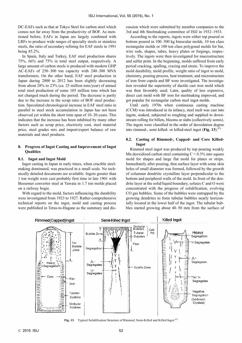
© 2015 ISIJ 52
ISIJ International, Vol. 55 (2015), No. 1
DC-EAFs such as that at Tokyo Steel for carbon steel whichcomes not far away from the productivity of BOF. As men-tioned before, EAFs in Japan are largely combined withLRFs to produce wide ranges of specialty steels or stainlesssteels, the ratio of secondary refining for EAF steels in 1991being 85.2%.
In Spain, Italy and Turkey, EAF steel production shares75%, 66% and 75% in total steel output, respectively. Alarge amount of carbon steels is produced with modern GHPAC-EAFs of 250–300 ton capacity with 240–300 MVAtransformers. On the other hand, EAF steel production inJapan during 2000 to 2012 has been slightly decreasingfrom about 28% to 23% (ca. 25 million tons/year) of annualtotal steel production of some 105 million tons which hasnot changed much during the period. The decrease is partlydue to the increase in the scrap ratio of BOF steel produc-tion. Speculated chronological increase in EAF steel ratio inparallel to steel stock accumulation in Japan has not beenobserved yet within the short time span of 10–20 years. Thisindicates that the increase has been inhibited by many otherfactors such as scrap price, electricity cost, steel materialprice, steel grades mix and import/export balance of rawmaterials and steel products.
8. Progress of Ingot Casting and Improvement of IngotQualities
8.1. Ingot and Ingot MoldIngot casting in Japan in early times, when crucible steel-
making dominated, was practiced in a small scale. No tech-nically detailed documents are available. Ingots greater than1 ton weight were cast probably first time in late 1901 withBessemer converter steel at Yawata in 1.7 ton molds placedon a railway bogie.
With regard to the mold, factors influencing the durabilitywere investigated from 1923 to 1927. Rather comprehensivetechnical reports on the ingot, mold and casting processwere published in Tetsu-to-Hagane as the summary and dis-
cussion which were submitted by member companies to the3rd and 4th Steelmaking committee of ISIJ in 1932–1933.
According to the reports, ingots were either top poured orbottom poured in 100–300 kg binocular molds, 10 ton classrectangular molds or 100 ton class polygonal molds for bar,wire rods, shapes, tubes, heavy plates or forgings, respec-tively. The ingots were then investigated for macrostructureand sulfur print. In the beginning, molds suffered from earlyperiod cracking, spalling, crazing and strain. To improve themold durability, mold profile, weight ratio of ingot to mold,chemistry, pouring process, heat treatment, and microstructureof iron from cupola and BF were investigated. The investiga-tion revealed the superiority of ductile cast iron mold whichwas then favorably used. Later, quality of less expensive,direct cast mold with BF iron for steelmaking improved, andgot popular for rectangular carbon steel ingot molds.
Until early 1970s when continuous casting machine(CCM) was introduced in its infancy, steel melt was cast intoingots, soaked, subjected to roughing and supplied to down-stream rolling for billets, blooms or slabs (collectively semis).The ingots were classified in the order of deoxidation degreeinto rimmed-, semi killed- or killed-steel ingot (Fig. 13).47)
8.2. Casting of Rimmed-, Capped- and Core Killed-Ingot
Rimmed steel ingot was produced by top pouring weaklyMn deoxidized carbon steel containing C < 0.3% into squaremold for shapes and large flat mold for plates or strips.Immediately after pouring, thin surface layer with some skinholes of small diameter was formed, followed by the growthof columnar dendritic crystalline layer perpendicular to thebottom and peripheral walls of the mold. In front of the den-drite layer at the solid/liquid boundary, solutes C and O wereconcentrated with the progress of solidification, evolvingCO gas bubbles. Some of the bubbles were entrapped by thegrowing dendrites to form tubular bubbles nearly horizon-tally located in the lower half of the ingot. The tubular bub-bles started growing about 40–50 mm from the surface of
Fig. 13. Typical Solidification Structure of Rimmed, Semi-Killed and Killed Ingot.47)

ISIJ International, Vol. 55 (2015), No. 1
53 © 2015 ISIJ
the ingot, the distance being controlled by the composition,cooling rate, pouring rate of the melt and the amount ofminor addition of Al to the melt. The solidified shell layerfrom the ingot surface to the end of the tubular bubbles,called rim layer, was negatively segregated and clean, andthe ingot was named rimmed ingot since it was surroundedby the rim layer (Fig 13, left).
CO bubbles other than entrapped ones left from theboundary, agglomerated, and ascended along the solidifica-tion front together with melt flow to reach the top surfacein the mold where they broke up, forming sparks by air oxi-dation of splash droplets. In the upper half of the ingot, stat-ic pressure of the melt was lower, and hence CO bubblesformed at the boundary grew faster, left the boundary fasterwithout forming tubular bubbles, and ascended with themelt along the boundary to the top to break up. Metal drop-lets formed at the break up burned up as sparks. The meltflow, partly oxidized at the top surface, descended throughthe central part of the ingot, forming strong circulating flowdirected to the top again. The circulating flow was accom-panied with many CO bubbles, looked from the mold toplike boiling to form the rimmed layer, and hence it wascalled rimming action. It was quite a show to see greatamount of the sparks arising from the top of large ingotmolds which were lined up on the bogies.
Oxides occurred in the ingot in various ways as the air oxi-dation product of melt stream during pouring and on the topof melt in the mold, entrapped eroded refractory and ladleslag, and agglomerates of endogenous inclusions formed dur-ing solidification. They were engulfed in the circulating flow,and largely carried back to the top of the mold as scum.
Skin holes were scaled off due to the oxidation of the skinlayer during the reheating of the ingot in a soaking pit forroughing. As long as reasonable thickness from the ingotsurface to the starting point of the tubular bubbles wassecured, the bubbles were not exposed to air and remain freefrom air oxidation, and hence clean and ductile surface wasobtained on the rolled product. Further progress of solidifi-cation formed debris of sediment crystals with negative seg-regation of solutes but with entrapped large inclusions at thebottom of the ingot. The entrapping of large inclusions wasdue to the showering sedimentation of equiaxed crystalswhich formed the debris.
Above the debris, inner core was formed due to acceler-ated solidification. Solutes were enriched and globular bub-bles were dispersed irregularly in and around the inner core.Top of the ingot solidified earlier than the whole of the ingotas a result of the termination of the rimming action and radi-ation heat loss from the top surface. From above the innercore around the vertical central axis to the top of the ingot,many sulfide precipitates appeared. As the inner core wassubject to accelerated solidification, however, large shrink-age cavities and heavy segregation, often observed in akilled ingot, did not from, resulting in a better yield of soundpart of the ingot. During 80% period of complete solidifica-tion, the ingots in mold on the bogie should be kept stand stillwithout applying turbulent wavy motion by controlling thetrack time of bogie to avoid anomalous segregation formation.
For the rimmed ingot making, British Iron and SteelAssociation (BISRA) published comprehensive pioneeringwork done until 192848) as did Swedish Iron and Steel Asso-
ciation (Jernkontoret) in 1939. The two works contributedgreatly to the progress of relevant research in Japan. Manystudies were carried out since 1934 in Japan on the distri-bution of surface bubbles, location, size and formationmechanism of the tubular bubbles and inner bubbles, anddistribution and formation mechanism of inclusions andsegregation of C, P and S.
In the period when high productivity ingot making wasdemanded, capped ingots were produced which intended tostop rimming action in the midway and suppress any furtherair oxidation with thick cast iron lid placed on the open sur-face of steel melt to quench and solidify the surface.Rimmed and capped ingots were favorably applied to themass production of various cold rolled strip and surfacetreated strip owing to their superior surface quality and highyield on rolling. Also, utilizing rimming action in the earlyperiod after pouring rimming ingots, Al was added to deox-idize and stop rimming action after about 20 mm thicksound and clean rim layer was formed in the ingots. Thistype of ingot was named core killed ingots which were lessexpensive than Al killed ingots, better for surface qualitywith decent interior quality, and hence used in a mass forpress forming strip for automobile.
8.3. Casting of Semi Killed Steel IngotSemi killed steel was developed in the USA. It became
popular in Japan since 1955 for lower S segregation thanrimmed ingots and better yield than killed flat ingot for platedue to decreased segregation and shrinkage in the top partof the ingot. Weakly Si deoxidized steel melt was pouredwith minor amount of Al addition to control the degree ofdeoxidation to form tubular bubbles in the upper half of theingot. The deoxidation degree was monitored and controlledby the shape of the swelling of the ingot top which opti-mized globular bubble distribution and the shape and size oftubular bubbles in the upper part of the ingot. The swellingwas also influenced by ingot size, width to thickness ratioof ingot, melt temperature at pouring and pouring time. S-segregation of semi killed ingot increased when the tracktime from the end of pouring and charging into soaking pitdecreased. Accordingly, track time was kept longer than80% of the time required for complete solidification of theingot as it was the case for rimmed ingot. The use of semikilled steel plates for the outer hull of ship minimized theseparation fracture of the plate on welding, greatly savingship from wrecks.
8.4. Casting of Killed Steel47)
Killed steels were cast into ingot long since Si deoxidizedacidic open hearth steel got popular. Melt refined in EAF forspecialty steels was also cast as killed steel ingots for a longtime. These ingots were cast with steels strongly deoxidizedwith Si, Si–Mn and/or Al. For particular applications, car-bon steel deoxidized under vacuum was cast as killed ingot.Strongly deoxidized steel does not produce CO gas bubbles,keeping the melt in the mold quiet, and hence called killedsteel. To compensate for the solidification shrinkage in ingotbody with steel melt fed from the top of the ingot, liningwith heat insulating refractory board or exothermic refrac-tory board was placed around the inner walls of the mold toptogether with flux powder addition to cover the top to delay
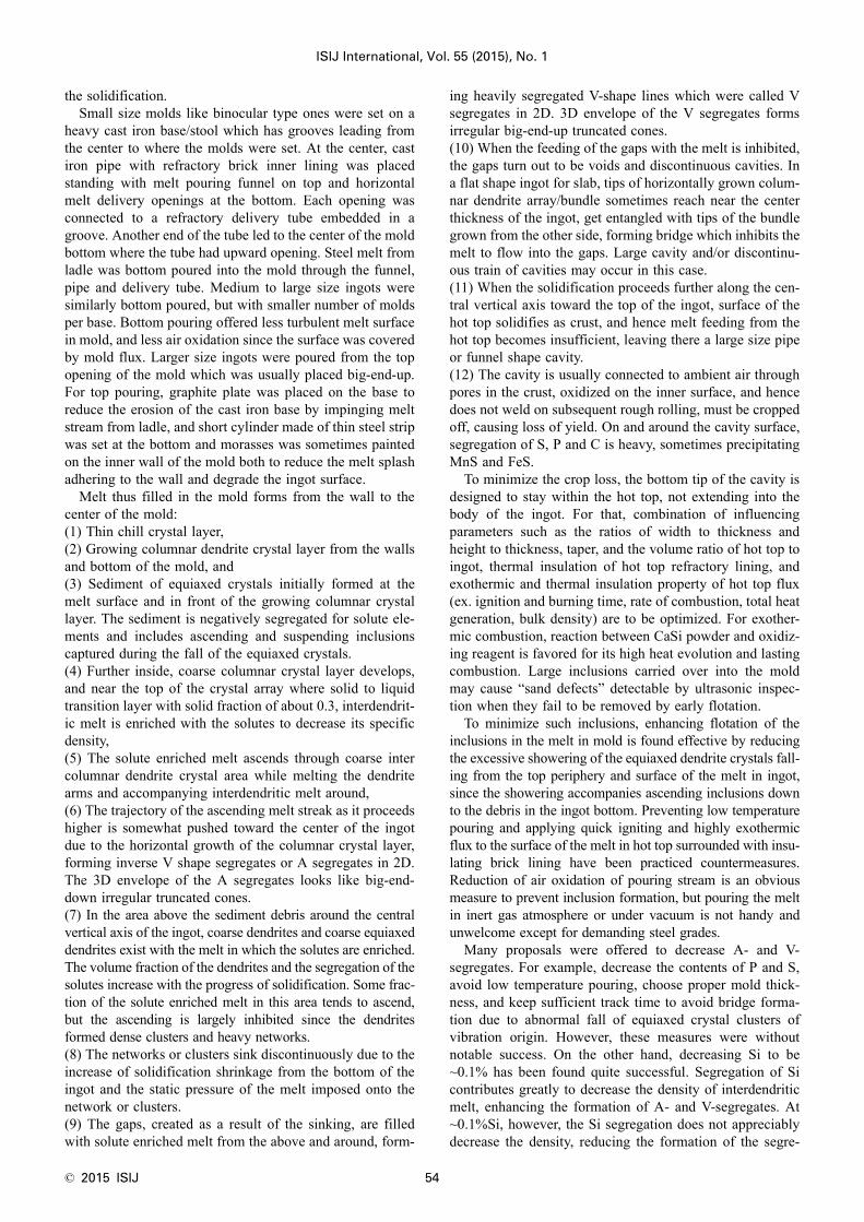
© 2015 ISIJ 54
ISIJ International, Vol. 55 (2015), No. 1
the solidification.Small size molds like binocular type ones were set on a
heavy cast iron base/stool which has grooves leading fromthe center to where the molds were set. At the center, castiron pipe with refractory brick inner lining was placedstanding with melt pouring funnel on top and horizontalmelt delivery openings at the bottom. Each opening wasconnected to a refractory delivery tube embedded in agroove. Another end of the tube led to the center of the moldbottom where the tube had upward opening. Steel melt fromladle was bottom poured into the mold through the funnel,pipe and delivery tube. Medium to large size ingots weresimilarly bottom poured, but with smaller number of moldsper base. Bottom pouring offered less turbulent melt surfacein mold, and less air oxidation since the surface was coveredby mold flux. Larger size ingots were poured from the topopening of the mold which was usually placed big-end-up.For top pouring, graphite plate was placed on the base toreduce the erosion of the cast iron base by impinging meltstream from ladle, and short cylinder made of thin steel stripwas set at the bottom and morasses was sometimes paintedon the inner wall of the mold both to reduce the melt splashadhering to the wall and degrade the ingot surface.
Melt thus filled in the mold forms from the wall to thecenter of the mold:(1) Thin chill crystal layer,(2) Growing columnar dendrite crystal layer from the wallsand bottom of the mold, and(3) Sediment of equiaxed crystals initially formed at themelt surface and in front of the growing columnar crystallayer. The sediment is negatively segregated for solute ele-ments and includes ascending and suspending inclusionscaptured during the fall of the equiaxed crystals.(4) Further inside, coarse columnar crystal layer develops,and near the top of the crystal array where solid to liquidtransition layer with solid fraction of about 0.3, interdendrit-ic melt is enriched with the solutes to decrease its specificdensity,(5) The solute enriched melt ascends through coarse intercolumnar dendrite crystal area while melting the dendritearms and accompanying interdendritic melt around,(6) The trajectory of the ascending melt streak as it proceedshigher is somewhat pushed toward the center of the ingotdue to the horizontal growth of the columnar crystal layer,forming inverse V shape segregates or A segregates in 2D.The 3D envelope of the A segregates looks like big-end-down irregular truncated cones.(7) In the area above the sediment debris around the centralvertical axis of the ingot, coarse dendrites and coarse equiaxeddendrites exist with the melt in which the solutes are enriched.The volume fraction of the dendrites and the segregation of thesolutes increase with the progress of solidification. Some frac-tion of the solute enriched melt in this area tends to ascend,but the ascending is largely inhibited since the dendritesformed dense clusters and heavy networks.(8) The networks or clusters sink discontinuously due to theincrease of solidification shrinkage from the bottom of theingot and the static pressure of the melt imposed onto thenetwork or clusters.(9) The gaps, created as a result of the sinking, are filledwith solute enriched melt from the above and around, form-
ing heavily segregated V-shape lines which were called Vsegregates in 2D. 3D envelope of the V segregates formsirregular big-end-up truncated cones.(10) When the feeding of the gaps with the melt is inhibited,the gaps turn out to be voids and discontinuous cavities. Ina flat shape ingot for slab, tips of horizontally grown colum-nar dendrite array/bundle sometimes reach near the centerthickness of the ingot, get entangled with tips of the bundlegrown from the other side, forming bridge which inhibits themelt to flow into the gaps. Large cavity and/or discontinu-ous train of cavities may occur in this case.(11) When the solidification proceeds further along the cen-tral vertical axis toward the top of the ingot, surface of thehot top solidifies as crust, and hence melt feeding from thehot top becomes insufficient, leaving there a large size pipeor funnel shape cavity.(12) The cavity is usually connected to ambient air throughpores in the crust, oxidized on the inner surface, and hencedoes not weld on subsequent rough rolling, must be croppedoff, causing loss of yield. On and around the cavity surface,segregation of S, P and C is heavy, sometimes precipitatingMnS and FeS.
To minimize the crop loss, the bottom tip of the cavity isdesigned to stay within the hot top, not extending into thebody of the ingot. For that, combination of influencingparameters such as the ratios of width to thickness andheight to thickness, taper, and the volume ratio of hot top toingot, thermal insulation of hot top refractory lining, andexothermic and thermal insulation property of hot top flux(ex. ignition and burning time, rate of combustion, total heatgeneration, bulk density) are to be optimized. For exother-mic combustion, reaction between CaSi powder and oxidiz-ing reagent is favored for its high heat evolution and lastingcombustion. Large inclusions carried over into the moldmay cause “sand defects” detectable by ultrasonic inspec-tion when they fail to be removed by early flotation.
To minimize such inclusions, enhancing flotation of theinclusions in the melt in mold is found effective by reducingthe excessive showering of the equiaxed dendrite crystals fall-ing from the top periphery and surface of the melt in ingot,since the showering accompanies ascending inclusions downto the debris in the ingot bottom. Preventing low temperaturepouring and applying quick igniting and highly exothermicflux to the surface of the melt in hot top surrounded with insu-lating brick lining have been practiced countermeasures.Reduction of air oxidation of pouring stream is an obviousmeasure to prevent inclusion formation, but pouring the meltin inert gas atmosphere or under vacuum is not handy andunwelcome except for demanding steel grades.
Many proposals were offered to decrease A- and V-segregates. For example, decrease the contents of P and S,avoid low temperature pouring, choose proper mold thick-ness, and keep sufficient track time to avoid bridge forma-tion due to abnormal fall of equiaxed crystal clusters ofvibration origin. However, these measures were withoutnotable success. On the other hand, decreasing Si to be~0.1% has been found quite successful. Segregation of Sicontributes greatly to decrease the density of interdendriticmelt, enhancing the formation of A- and V-segregates. At~0.1%Si, however, the Si segregation does not appreciablydecrease the density, reducing the formation of the segre-

ISIJ International, Vol. 55 (2015), No. 1
55 © 2015 ISIJ
gates as proposed and confirmed by Yamada et al.49)
In this way, valuable technological developments weremade to improve the productivity and quality of rimmed-,semi killed- and killed ingot. Since 1970, however, ingot cast-ing has been replaced with quickly developed continuouscasting, producing only limited amount of ingots withdeclined number of R & D, except for special casting andextra heavy ingots for forgings which have shown the fol-lowing continued progress.
8.5. Casting Ingots for Extra Large Forgings and ExtraHeavy Plates and ESR Ingots
Japan Steel Works revealed its technology in 1989 tocommercially cast 500 ton class ingot for forgings. Severalheats of EAF steel melt were stream degassed and toppoured into mold in sequence under vacuum to removehydrogen while preventing air oxidation. To counter the seg-regation of C in the ingot with the progress of solidification,C content of subsequent heats for pouring were decreasedheat after heat.50) A growth model for solidified fraction ofthe ingot with equilibrium partition coefficients of C made itpossible to estimate the segregation ratio of C in the remain-ing melt in the ingot. To dilute the segregation to meet the aimC, necessary temperature and C content were calculated forthe next heat, which were tapped from EAFs and poured intothe ingot. This method was worked out due to the constraintof limited EAF capacity, but showed a peak of technologyaccomplished to cast the extra heavy ingot at that time.
For special applications, Sumitomo metal commercial-ized horizontal ingot casting which employed low heightrectangular mold for unidirectional solidification from bot-tom to top. After solidification completed, top of the flatingot, where solute elements were segregated, wasmachined off for finish rolling. NKK industrialized 140 tonclass hollow ingot casting for large hollow forgings. Forgreater size ingots, Japan Steel Works and Japan Cast Steeland Forging Steel have industrialized casting of 650–670ton ingots and 650 ton ingot, respectively, in 2009–2011,successfully producing extra large low pressure turbinerotors for power generation.51)
There have been progresses in large scale electro slagremelting and casting (ESR), too. Japan Steel Worksrevamped 100 ton ESR in 2011, and introduced world larg-est class 150 ton ESR facility with single electrode and2 200 mm diameter fixed mold. Precision of the melting andsolidification operation has been upgraded to the extent thatsingle electrodes are exchanged multiple times to make thelarge ingot with low frequency power source to reduce elec-tricity consumption.52)
9. Development toward High Quality and High Produc-tivity Continuous Casting
9.1. Continuous Casting Technology in Early Stage ofIntroduction3,13,14,53,54)
Development of continuous casting machine (CCM) withoscillating mold started in 1949 when Junghans in Germanyand Rossi in USA trialed such CCM on the basis of the pat-ent by Junghans. Industrial implementation of the CCM inJapan started in 1955 when Sumitomo Metal got license tosell and operate Rossi Continuous Casting Machine (RCCM),
and commercially built and operated at Osaka Steel Worksone strand vertical billet RCCM to produce rods for spring andwheel stopper for train. For stainless steel slab and bloom,Hikari put one strand vertical RCCM at the end of 1960.
RCCM at that time was technically not mature yet, andhence problems happened on the machines and operation.The problems were solved by 1964. The two RCCM operatedsuccessfully with accumulated technical understandings andoperational skill, and the yield of the cast strands were con-firmed to be better than ingot casting route by several percent-ages. However, the productivity in terms of metal-in-moldtime of RCCM was less than 10%, casting rate was a low 15tons/h, investment required was about 1.5 times of the ingotcasting, accidental shut down occurred sometimes and qualityof the cast semis was unsatisfactory. These drawbacks madethe RCCMs not built until early 1960s in integrated iron andsteel plants by the sea consisting of large BFs and BOFs.
After that period, EAF mini-mills evaluated future poten-tial for the development of CCM for their own circumstances,and constructed in sequence the followings:
Kitanihon Tokusyukou (North Japan Specialty Steel),Mannesmann Demag vertical billet and slab CCM in 1964,the first one in Japan, Nippon Yakin, Concast vertical slabCCM and Kokkou Seikou, Concast curved (S-type) billetCCM both in 1965 as the 1st ones in Japan, Tohoku Satetsu,Olsson vertical and progressive bending billet CCM in1965, the first in Japan. These CCMs were followed in 1967by Osaka Seiko’s Concast curved billet CCM and DaiwaSeiko’s Concast curved slab CCM, and Nihon Kinzoku’sOlsson vertical slab CCM.
Integrated steel plants also put the following CCMs intooperation during 1964 and 1967, i.e., Kobe Steel Kobe, USSRtype vertical multi strand billet CCM and bloom and slabCCM first time in 1964, NKK Tsurumi, DST type curved slabCCM first time, Yawata, Olsson vertical bending 6 strand bil-let CCM, Nissin Kure, USSR type slab CCM and SumitomoKokura Concast curved 6 strand billet CCM, all in 1967.
Acquired experiences of the construction and operation ofthese CCMs and relevant information on the CCMs abroad(mostly Germany and USSR) gained credit with integratedsteel plants on the reliability and economy of the CCMscombined with BOFs, promoting further implementation ofCCM to mass produce carbon steel semis. However, produc-tion of CC steel semis at that time with 10 billet CCMs, 2bloom CCMs and 5 slab CCMs in total remained a small 5%or less of the annual crude steel production of 60 million tons.
In view of technologies, implemented in CCM and CCoperation were;(1) Application of warm forged Cu–Ag alloy for mold,(2) Use of ZrO2·SiO2 nozzle for tundish,(3) Domestic manufacture of thermometer and spray nozzle,and(4) Use of imported mold fluxes and silica base submergedentry nozzle (SEN).
Also, continuous-continuous casting technique was prac-ticed to considerably improve the ratio of [metal-in-mold time(%)] to [yield of cast semi (%)] from [50/95.8] for single heatcast to [76/98.0] for 3 heats cast, [83/98.4] for 5 heats cast and[92/98.8] for 10 heats cast in sequence, but not quite.
To be consistent with the productivity of BOF at mini-mized construction cost while capable of sequence casting

© 2015 ISIJ 56
ISIJ International, Vol. 55 (2015), No. 1
slabs of the width for strips and plates, curved CCM, whichfits in the height of existing casting bay building, was firstcommissioned at Tsurumi in 1967 for plates. The choice wastaken since Concast S-type curved CCM operated successful-ly for plates at Dillinger, Germany in combination with largecapacity BOHs. At Tsurumi, 100 ton LD was combined withMannesmann curved CCM for plates, equipped with:(1) Ladle Ar bubbling,(2) Al wire injection into ladle for deoxidation,(3) Feeding steel melt from ladle to tundish via. Ar shroudedlong nozzle to reduce both air reoxidation of the melt andcarry over of ladle slag into tundish,(4) Melt transfer from tundish to mold via. SEN and(5) Casting with mold flux powder (powder casting).
Casting performance was so successful that 40 ktons/mo.of the melt were cast without break out for 6 900 heats intwo years period. In the above, terms (1)–(5) are still impor-tant basics to sustain CC operation. Qualities of the castslabs were better than the slabs of rimmed and semi killedingot origin, meeting the demanding specification of linepipe steel plate API5LX52. In fact, 30% of the total amountof cast slabs was for the line pipe plate. For blooms, Concast8 strand curved CCM was combined with 180 ton BOF tomass produce 43 ktons/mo. of carbon steel at Mizushima.
9.2. Enhancing the Productivity of Curved CCM atIntegrated Steel Plants13–15,54,55)
Credibility of the curved CCM as a mass production facil-ity compatible to BOF was confirmed as above in late 1960sto let integrated steel plants in Japan rush to adopt the com-bination of BOF and curved CCM since 1970. Oita com-bined three Hitachi Zosen-Demag curved CCMs with three330 ton BOFs, starting a unique fully continuous castingplant first time in Japan in 1972. Metal-in-mold time wasmuch improved with:(1) Large tundish,(2) Top insert of dummy bar,(3) Swing tower to exchange ladles,(4) Melt level sensing in mold with thermocouples,(5) System to quickly exchange the cassette stand modulecontaining mold, mold oscillation mechanism and slab sup-port rolls,(6) Long mold to cast slabs at a high speed of 2 m/min,(7) Slide nozzle for melt transfer from tundish to mold,(8) Casting in a constant width mold followed by width sizingup to 125 mm at roughing mill in hot rolling plant, and(9) Automatic casting operation.
Over 50% of crude steel at that time was cast as rimmedsteel ingots for better yield, formability and surface quality,and hence open cast Riband Steel technology for CC devel-oped by US Steel was introduced to replace the rimmedingots. Compression casting technology developed also byUS Steel was adopted to avoid internal cracks which format one point bending during high speed slab casting. Oitastarted casting in April, 1972 and soon achieved a worldrecord of over 320 ktons/mo. of cast strands with the threeCCMs in Aug. 1973. Among the three, No. 1 CCM markedanother world record of casting 161 ktons/mo.
It was in 1973 when all Japan production of CC semisreached 16.67 million tons, 20% of annual crude steel pro-duction. Throughout the early half of 1970s, Japanese steel
companies made efforts to stably maximize the output ofCCMs (in total 19) while minimizing the occurrence ofdefects of strand cast at a high speed. Technologies devel-oped for the objectives include:(1) Top insert dummy bar as mentioned before,(2) Erosion resistant refractory material for long nozzle andSEN (non-fused silica, alumina-graphite),(3) Tundish slide gate and Ar seal at the boundaries oftundish/slide gate and slide gate/ SEN,(4) Reduction of air oxidation during the melt transfer fromladle to tundish by use of Ar seal box or long nozzle,(5) Protection against the surface oxidation of tundish meltwith Ar or tundish flux,(6) Use of large tundish and control the flow and stream lineof the melt in tundish with furniture for inclusion removal,(7) Quick tundish exchange system,(8) Establishing the use of SEN in combination with powdercasting as a routine,(9) Quick exchange of SEN during casting as exemplifiedby Kashima in 1978 (only in 1 min with 1 person),(10) Soft cooling and better lubrication at mold/cast strandboundary with improved mold flux,(11) Electromagnetic melt level sensor for mold as devel-oped by NKK, which is superior in sensitivity to conven-tional sensors with radio isotope or thermocouple,(12) Rationalization of water cooling channels in mold,(13) System to acquire and process the data for temperaturedistribution in the mold plate measured with embeddedarray of thermocouples and friction force determined withMold Tektor by CRM, Belgium at mold/cast strand bound-ary, both for preventing sticker break out. Incidentally, thebreakout occurs when the shell of the cast strand welds oradheres to the mold wall and is torn as the strand is with-drawn out of the mold,(14) High cycle oscillation of mold which makes oscillationmarks on the cast strand surface shallow and decreases bothheat transfer resistance across the marks and solute segrega-tion in the marks, contributing to reduce transverse surfacecracks,(15) Improvement of cast strand support mechanism andwater cooling below the bottom of the mold (cooling gridor plate),(16) Optimization of the cooling of wear resistant mold bythe choice of material, plating, taper, and length of the mold.The length converged to about 900 mm from longer moldwith corner slit for water cooling,(17) Previously mentioned quick exchange system of thecassette stand with manipulator,(18) Selection of wide angle water spray nozzle chips for thesecondary cooling system. The chips prevented spray nozzleclogging and reduced surface defects and internal cracks,(19) Optimization of 2D water spray pattern to fit the steelgrades and the width of cast strand,(20) Precise control of roll gap and roll alignment,(21) Adoption of smaller diameter split rolls to firmly sup-port the strand to decrease the bulging, and(22) Automatic casting operation with comprehensive con-trol of the tundish slide gate, melt level sensor in the mold,and pinch roll and dummy bar as materialized in 1973 atWakayama.
For strand cleanliness, contradictory demand to increase

ISIJ International, Vol. 55 (2015), No. 1
57 © 2015 ISIJ
casting speed while decreasing inclusion engulfment wassomewhat resolved by limiting circle radius (as used for theS-type curved CCM) of the strand to be 30–50 times of thestrand thickness, and making the metallurgical length*extended by straightening the strand to horizontal directionat 1/4 point of the circle (*The distance from the melt levelin mold to the point where the strand solidifies completely =time required for through thickness solidification × castingspeed). This helped the height of plant building reduced tosave construction cost.
CC is in essence a near net shape casting process. Devel-opment to this direction was made in 1973 to cast H-shapewith H-section beam blank CCM at Mizushima and in 1974round section centrifugal bloom CCM at Keihin for seam-less pipe. Maximum size of CC strands reached 300 mmthickness × 400 mm width for bloom and (250–300) mmthickness × (2 000–2 400) mm width for slab. With thedevelopments mentioned in 9.1–9.2, CC ratio for slab inJapan achieved 32.8%.
Productivity of CCM kept increasing since. Number ofheats continuously cast in sequence per one dummy barinsert rose to 270 at Tsurumi in 1974, followed by over 200at Yawata and Mizushima. To make such long sequence CCoperation possible, employed were:(1) Technology for simultaneous exchange of ladle andtundish during casting,(2) Sequence casting technology of different grades devel-oped in USA where the mixing of preceding and succeedingheat was prevented and the two heats were mechanicallyconnected by chill metal device placed in between, and(3) Width change technology where narrow faces of themold were either set back or push forward to get broader ornarrower width strand without interrupting the casting asdeveloped in 1975 at Mizushima. Rating up of the widthchange was developed further in 1983 at Sakai where vari-able taper and face shift type narrow face driven mold wascommercialized, resulting in the width change speed up to100 mm/min/side at casting speed of 1.8 m/min.
In those days, RH degassed and lightly Al killed CC steeldeveloped at Oita from deoxidation controlled Riband steelwas recognized better in productivity, cost and quality con-sistency than rimmed ingot steel. The former replaced,therefore, the latter which shared more than half of total
ingot production in Japan. In 1976, NKK took the initiativeto apply light inline roll reduction at the melt pool end inCC strand to reduce the segregation and porosity occurringin the center thickness of CC slabs. Also, Tsurumi started hotcharge rolling (HCR) and direct hot charge rolling (DHCR)of CC slabs for energy saving, decreasing about 360 MJ/tonversus conventional cold charge rolling. A step forward,Sakai industrialized hot direct rolling (HDR) in 1981.
Although circular CCM in this way exhibited the advantagesand contributed to the proliferation of CCM, it has inevitabledisadvantage to cause 1/4 thickness accumulation of largeinclusions from the upper surface of the strand. The accumula-tion is due to the capture of large exogenous inclusions broughtin and ascending out of the melt pool in the strand, and is det-rimental to the mechanical properties of demanding products.
9.3. Evolution of Vertical Liquid Core Strand BendingType Slab CCM19,54,55)
The upper quarter thickness accumulation of large inclu-sions increased with casting speed of CCM. Vertical solidcore strand bending (VSB) type CCM was a solution butwith drawbacks of increased building height and slowercasting speed. As a better solution, Chiba introduced in1974 a vertical liquid core strand bending (VLB) type CCMdeveloped by Vöest-IHI. It has about 2.5 m long verticalentry (mold inclusive), followed by progressive bending atmultiple points and multiple point unbending of strand withliquid core to reduce the accumulation at higher castingspeeds. The VLB CCM was still in its infancy, and hencecasting operation in early times suffered from insufficientrigidity of support roll segments and the fracture of rollersin the bearings for the support rolls. After solving the prob-lems, however, the accumulation was drastically decreased toenable the casting of slabs for HIC resistant plate for line pipe.
Soon later, VLB CCMs were introduced successfully in1976 at Keihin (SMI-Concast make), Kimitsu in 1980(Hitachi Zosen-Demag make), and Fukuyama where circu-lar CCM was converted by Hitachi Zosen-Demag to VLBin 1980. Since then, new installations of VLB CCMs (Fig.14)84) were many in other steel plants in Japan. In Europeand USA, it took longer time for the implementation, butrecently, the installation has been increasing, following theone at Dillinger. To deal with more demanding qualities,
Fig. 14. Advanced Vertical Liquid Core Bending Continuous Caster at NKK.84)

© 2015 ISIJ 58
ISIJ International, Vol. 55 (2015), No. 1
VSB CCMs with longer vertical part of strands were putinto operation in 1976 at Mizushima and Keihin.
The CC ratio reached 89.1% of total crude steel produc-tion in Japan in 1984. Progress in operational skill, adoptionof multiple taper narrow faces for mold, and mist spray forsecondary cooling of the strands to reduce surface defectscaused by the embrittlement at elevated temperatures, allcontributed to increase the ratio of hot charge rolling (HCR)of cast slabs in many steel plants. On the other hand, hotdirect rolling (HDR) and direct hot charge rolling (DHCR)of cast slabs have been limited to strands for hot rolled strip,not prevailed to strands for plate due to lot size limitationand quality issues.
Accordingly, the productivity of CCM further increased,some of them up to 200–250 ktons/mo. To guarantee the qual-ities of strand, the roll gap, roll alignment, irregularity of rollrotation and clogging of spray nozzle for secondary coolingbefore casting are inspected with inline multiple functionchecker which passes through the roll gap with dummy bar,transmits the measured data wireless for correction. Thechecker data and corrective actions have been found effectiveto decrease the surface cracks and internal cracks arising fromstrand bulging. Substantial developments in the system designand the mechanism for CCM by this time are detailed in agood review after Harabuchi and Pehlke.53)
9.4. Highly Productive High Speed Slab Casting ofHigh Quality Steels33,54–57)
During the latter half of 1980s, the productivity advantageobtainable by prolonging metal-in-mold time with the superlong sequence of continuous continuous casting operationwas largely offset by the downgrading of slab qualities. Thedowngrading loss occurred at the unsteady part of casting,i.e., joints of heats where melt contamination took place inassociation with many times of tundish exchange operation.The loss became profound with stricter demands for theallowance on the subsurface and internal inclusions, centersegregation and porosity of the strand.
To prevent the loss, measures have been industrializedincluding:(1) Transfer of steel melt without contamination from ladleto tundish and tundish to mold,(2) Minimizing temperature drop of the melt during thetransfer,
(3) Rationalizing tundish structure,(4) Optimizing melt flow in mold, and(5) Inline reduction of the cast strand.
For preventing the air oxidation, seal box structure is oneway where ladle and tundish are connected with a cylinderfilled with Ar. Also, Ar is injected into the space between themelt surface and tundish lid set airtight on the top peripheryof tundish to keep the tundish melt free from air oxidation.Another way is to pour the melt from ladle into tundishthrough Ar-sealed long refractory nozzle, while the melt sur-face in tundish is covered with non-oxidizing lime or limealuminate slag to keep away from air oxidation. In addition:(1) Air tightness of the melt transfer route is made better,(2) Carry over of FetO bearing ladle slag is made minimal,(3) Starting tundish-open only after filling tundish to a cer-tain depth (>minimum 600 mm),(4) Employ large volume tundish (> 65 ton for two strandslab caster),(5) Always keep the tundish melt level >1.2 m during steadystate casting to minimize the carry over of tundish slag intomold by vortex flow which may occur in tundish otherwise,and(6) Inhibit the short circuit flow of melt from impingingpoint below ladle to exit nozzle of tundish.
A large 85 ton tundish58) successfully commercialized atKobe is a typical example in line with the above concept inall aspects.
For super clean steel grades, a solution has been providedby Chiba in 1996 in the form of Centrifugal (CF) tundish(Fig. 15).59) It consists of a cylindrical front chamber whereinclusions in the melt from ladle are separated to the centralconcave cavity of the melt generated with progressive circu-lating electromagnetic field set around the cylinder chamber.Cleaned steel flows out of a bottom opening of the cylinderchamber into rectangular rear chamber which has an oppositebottom opening to deliver the melt into mold. CF tundish hasexhibited high ratio of inclusion separation, commercializedto cast high quality steels with excellent cleanliness.
Another development, H-shape tundish, has been made atNagoya in 2000. It consists of two rectangular chambersconnected side by side with bottom through hole to form H-shape tundish (Fig. 16).60) Two ladles for preceding heat andsucceeding heat can be teemed into the 1st chamber simul-taneously, without causing the harmful lowering of the melt
Fig. 15. Centrifugal Flow (CF)-Tundish for Clean Steel Casting at Kawasaki Steel.59)

ISIJ International, Vol. 55 (2015), No. 1
59 © 2015 ISIJ
level in the chambers at the ladle change. 2nd chamber isequipped with DC arc heating guns to compensate for tem-perature drop of the melt within. At the bottom of thethrough hole, Ar injection plug is set to stir up all the pass-ing melt with fine Ar bubbles to let even fine inclusionsagglomerated and removed. Extended distance between themelt inlet point in the 1st chamber to melt exit point out ofthe 2nd chamber also favors inclusion flotation. The H-shape tundish has exhibited good capability to solve theproblems inherent to the joints of heats, ensuring clean steel
casting all over the heats.Transferring the cleaned melt from tundish to mold
through SEN requires special attention. Immersion depth ofSEN in the melt in mold, number of exit ports and angle ofinclination of the ports of SEN have been so designed as tominimize the penetration depth of the melt flow in the meltpool in strand, while not to cause the turbulence at theboundary of mold slag and steel melt by double roll typedeflected melt flow toward the upper part of the mold. Also,various measures to reduce SEN clogging have been elabo-rated, including minimization of inclusions, making inclu-sions molten, SEN structure to modify melt flow and SENmaterials to let inclusions coming in touch modified to bemelted, although none of them are fully satisfactory yet.
In addition, electromagnetic devices to control the meltflow in mold have been industrialized (Fig. 17)61,62) such asIn-Mold Electro-Magnetic Stirrer (M-EMS) pioneered in1980 at Hirohata, followed by Electro Magnetic Brake(EMBR) of ABB at Mizushima, later developed into FlowControlled Mold (FC-Mold) 85) of Kawasaki Steel, and LMFof Nippon Steel.
M-EMS accelerates and circulates upper part of the meltin mold horizontally with linear motor type parallel travel-ing magnetic field. The circulating melt flow washes awaythe solidification front of the strand shell, preventing thecapture of inclusions and gas bubbles to the shell, makes theinitial growth of the shell even to prevent the longitudinalcracks and break out of the shell. As a consequence, surfacequality and yield of the strand have been much improved.
EMBR or FC-Mold reduces the speed of melt stream outof SEN ports at the two sides of the mold width near the portexits (EMBR) or over the whole width at upper half andlower half of the mold (FC-Mold) with static magnetic fieldapplied through thickness direction of the mold. The pene-tration depth of the melt stream into the melt pool in thestrand is reduced, enabling faster removal of inclusions byflotation. At the same time, wavy motion of the melt surfaceis damped and turbulence at the mold slag/melt boundary isdecreased, both help decrease the mold slag engulfment into
Fig. 16. H-Shape Tundish for Clean Steel Casting at NipponSteel.60)
Fig. 17. Electromagnetic Melt Stirrer and Melt Flow Brake in Continuous Casting Mold61) (partly modified).

© 2015 ISIJ 60
ISIJ International, Vol. 55 (2015), No. 1
the pool. Some reheating of the strand shell periphery at themeniscus also occurs, reducing the hook formation there andconsequent inclusion trapping below the hook.
Fukuyama commercialized Electro Magnetic LevelAccelerator (EMLA) and Electro Magnetic Level Stabilizer(EMLS). The two employ traveling magnetic field,exchangeable by switching the cable connection. EMLAworks like M-EMS, while EMLS like EMBR. Lasting elab-oration was necessary for all the electromagnetic devicesmentioned above until maturation, but after the optimizationof the devices and operational parameters, all have becomeindispensable tool to achieve much improved cleanlinessand surface quality of strands.
Another progress was in Cu-alloy for mold which shouldstand against higher operating temperature caused by highspeed long sequence casting and high density magnetic fluximposed by the electromagnetic devices. The high temperaturestrength is materialized with precipitation hardening CrZrbearing Cu alloys. On top of the alloys, either spray coatingwith self-fluxing NiCr alloy or thick plating of FeNi alloy ismade for wear durability. These measures are effective in pre-venting the deformation of wide face plate of mold, have guar-anteed long campaign and eliminated the occurrence of starcracks which form when the surface coating/plating is lost andmold Cu penetrates into strand surface in contact.
Additional improvement of CCM productivity was nec-essary at this time to increase the HCR and combine CCMstreamlined with hot strip mill.15,19,33,54,55) In 1980, No.1CCM in No.3 Steelmaking Plant of Yawata successfully cast268 ktons/mo. at max. 2.0 m/min. No.5 CCM at Fukuyamaincreased casting speed to an average of 2.1 m/min and max.2.5 m/min in 1985 with a combination of high viscositymold flux, non-sinusoidal high cycle mold oscillation, moldtemperature control, high precision mold meniscus levelcontrol and secondary cooling control with mist spray. Opti-mizing mold melt flow, Fukuyama cast 302 ktons/mo. atmax. 2.7 m/min in 1990. Kashima No.3 CCM maximizedmetal-in-mold time by developing a technique to ending thecasting at a constant speed while start casting the next heatduring the ending, and cast 309 ktons/mo. at max. 2.0 m/minin 1989. No.2 CC at Nagoya also cast 301 ktons/mo. at max.2.2 m/min in 1993. Contrary to the high speed casting trend,Oita No.4 CCM directed toward a constant large sectionmold casting at a modest 1.48 m/min to reach 361 ktons/mo.productivity in 1985.
As mentioned, machine and operation for CC maturedcountry wide during the latter half of 1980 and the early halfof 1990 to attain over 80% for CCM availability, making theproductivity of CCM compatible to BOF, and CC ratioreached 95%. In parallel, the installation of and conversion toVLB type CCM have increased up to 46% to meet the demandfor high quality steels, and are still keeping increasing. Tohedge the quality decline at the joints of heats in sequentialcasting, high speed CCMs have been moving toward singlestrand type when the productivity matches with BOF.
Single strand CCM is beneficial to save costs formachine, operation, maintenance and labor. Typical exam-ple is Fukuyama No.6 CCM built in 1993 to produce 180ktons/mo. at 3 m/min. for which capacity and melt depth oftundish have been chosen to be 80 t and 1.2 m. Largetundish serves to enhance inclusion flotation and stabilize
strand quality with constant speed casting at the joints ofheats.
9.5. Temperature Control at Unsteady Part of CastingIncluding Joints of Heats33,54,55,57)
Even after secondary refining has become popular, melttemperature at the start, end and joints of heat tended todecrease below threshold value for quality certification.Lower temperatures are unfavorable for the inclusion sepa-ration and the hook formation. When the temperature isexcessively low, hooks get thicker to form surface cracks.Extremely low temperature leads to the formation of crustat the melt meniscus. The crust sinks into the melt pool withadhered mold slag, sediment in strand to cause harmful largemacro inclusions. When the temperature of the melt at thejoints is set at the optimum value for CC, melt temperaturekeeps rising with the progress of casting, decreasing the vol-ume fraction of sediment equiaxed crystal clusters at thepool bottom in strand, forming center segregation.
To prevent the temperature drop at the unsteady part,Hirohata industrialized first time in the world in 1987 a DCplasma arc heating of melt surface in large size tundish, fol-lowed by AC plasma arc heating by Kobe in 1990. For smallsize tundish, heating with channel type inductor was com-mercialized at Chiba and Muroran in 1986 and 1987. Theheating systems for tundish melt got popular at manyCCMs, contributing to normalize casting temperature andimprove strand qualities.
Instead of heating the tundish melt during continuouscontinuous casting, hot recycling of tundish was consideredbetter to retain heat and save tundish refractory. Here, at theend of casting, remained molten tundish slag is quicklydumped, tundish nozzle and SEN are exchanged on the fly,and renewed tundish is put into service as hot for a subse-quent casting to considerably decrease the temperature dropand refractory consumption. Kobe Kakogawa developedthis technology first in the world in 1989. After manyimprovements including automation of the exchange opera-tion, it became possible to cast 500 heats in sequence at ashort 25 min interval of the hot recycling.63) The success ofhot recycling made it introduced to many 1–2 strand CCMsbuilt in 1990s. Combined with the hot recycling, short peri-od of preheating and non-oxidizing preheating have enabledstarting the first heat casting with filled tundish after thetundish exchange, resulting in improved cleanliness andyield, reduction of refractory consumption by 90%, and con-siderable savings of labor and energy.
CC ratio in Japan kept increasing since to 99.5% for car-bon steel slabs for plates and 98% for the same for strip in1992. In 1998, the ratio for carbon steel slabs, blooms andbillets reached 99.5%, and for specialty steel 91.2%. CCtechnology really attained maturity in 2010 when the ratiosaccomplished 99.9% for carbon steel, 96.4% for specialtysteel, and 99.1% altogether.
9.6. Recent Progress in Casting High Quality Steels9.6.1. Non Metallic Inclusions
To meet ever increasing demands for the qualities andcost of cast strand, improving cleanliness, center segrega-tion, productivity, and premium yield of strand have beenthe central issues for CC in the last 20 years. For inclusions,

ISIJ International, Vol. 55 (2015), No. 1
61 © 2015 ISIJ
origin and measures to prevent and remove the macro inclu-sions arising from:(1) Carried over slags from BOF, ladle, tundish, and mold,(2) Alumina due to melt reoxidation by air and slag, and(3) Agglomerates/clusters of fine deoxidation products,have been made largely clear all across the melt path fromBOF to cast strand.
Inclusion problems in specialty steel slabs and billets,often repeated ones like MgO·Al2O3 spinel inclusions inbearing steel and TiN–Al2O3 complex inclusions in tire cordsteel, have also been diminished by similar measures,including the minimization of contamination with ladleglaze by means of proper ladle cycle management.
Inclusion problems are in some ways moving targetswhich vary as the quality requirements for final productsmade of cast semis become more stringent. For example,microstructure of TMCP-AcC steel and HSLA plate forlarge energy input welding is influenced by fine complexprecipitates. Kinetics and thermodynamics for the formationof the complex precipitates made of micro alloying elementsand S, O and N during the course of solidification and cool-ing may to some extent be estimated with Thermo Calc andFact*Sage in combination with melt flow and crystal growthsimulation.
However, the database for the calculation in dilute con-centration range is still insufficient and unreliable. To cal-culate the formation of fine CaMg (O, S) which serves asthe nuclei for the crystallization of fine bainite to retainHAZ ductility in the large heat input welding, the databasealso lacks precision and reliability.
Separation behavior of fine inclusions associated withagglomeration and dispersion of composite inclusions inmelt-bubble two phase flow field requires further investiga-tion to unveil the detailed reality. In this regard, CFD toolsand modeling have been made available. In fact, Miki etal.85) carried out an interesting simulation study on theengulfment of bubbles and inclusions in the early stage ofgrowing strand shell as influenced by melt flow and appliedmagnetic field for FC-Mold operation in CC mold, showinggood agreement with observation. Many body problem ofthe growth of multiple crystals/crystal bundles on solidifi-cation was dealt with by Steinbach in terms of multi phasefield theory with strikingly good agreement with observa-tions.86) Further progress in these issues is much expected.
BOF slag carried over from ladle into tundish has beentraditionally a major source of harmful macro inclusions intundish and mold. To prevent the carry over, attempts havebeen made for decades64) starting from a variety of throw-intype stoppers at BOF tap hole to a combination of AMEPAelectromagnetic slag sensor and pneumatic gas jet blowingwith butterfly stop valve or interstop CG120 at the tap hole.Some are shown effective, but not complete yet.
Clogging of SEN with alumina accretion has been anotherheadache, since it triggers biased flow and turbulence at moldslag/melt meniscus boundary, deteriorating strand quality.
Countermeasures proposed were:(1) Ar injection through inner bore of tundish nozzle and/orSEN to suppress aspiratory air permeation which forms alu-mina. The injection also reduces adhesion of alumina to theinner bore of SEN,(2) Air tight coating of the outer surface of SEN to prevent
the air permeation,(3) Smoothing treatment of the inner bore surface of SENto reduce alumina particle adhesion,(4) Conversion of alumina to low melting point lime alumi-nates with Ca addition to steel melt,(5) Apply lining of CaO base material to the inner surfaceof SEN to convert alumina to the lime aluminates,(6) Control melt flow in SEN with various refractory struc-tures to inhibit the adhesion of alumina particles.
Some of them were effective, but mixed view remainedon the others regarding the effectiveness due to unfavorableside effect. For the time being, therefore, reducing aluminainclusions in the melt and exchanging SEN on the fly are themainstay measures in addition to some of (1)–(6).
9.6.2. Center SegregationCenter segregation has been largely suppressed within
acceptable margin by the combination of decently low tem-perature casting with electromagnetic stirring to increaseequiaxed crystal fraction at the center thickness, followed bylight to medium reduction in the vicinity of pool end in thestrand shell. The above measures promote to disperse someof solute enriched melt into the boundaries of equiaxed crys-tals and others being pushed out into the pool. The reductionshould be controlled to squeeze the aimed solid fraction areaof the pool end uniformly all over the width. For that, sec-ondary cooling should be controlled uniform widthwise tomake the contour of the pool end flat without irregularity.
Degree and position of the reduction depend on the aimedsolid fraction which is influenced by the chemistry, strandthickness, cast temperature, cast speed and secondary cool-ing, and the rigidities of roll pair and roll housing. Accord-ingly, the precision of the automatic control system shouldbe upgraded to apply the reduction by dynamic calculationwith these variables. Each CCM plant in Japan has operatedlong since with its own system, prior to Dynacs 3D/DynamicGap-Soft Reduction by Siemens-VAI.
In view of more stringent user demands to decrease thesize and number of center segregation spots, however, theupgrading of the measures would be necessary soon. Theabove reduction in the roll gap at roll contact has its ownlimitation. Replacing the roll reduction by anvil reductionworked more effectively. In fact, area fraction of the segre-gation spots with Mn > 1.5% and P > 0.04% in CC slabsfor plate containing 0.06–0.10%C, 1.0–1.1%Mn, 0.004–0.008%P decreased to 0.03% by use of an anvil type reduc-tion. Like inclusion case, requirement for the critical sizeand number of center segregation spots is a moving target.As time goes by, more effective measures integrating thecooperation among EMS for mold and strand, strand bulg-ing management with better control of secondary coolingand roll gaps, and advanced reduction system need to bedeveloped.
9.6.3. Surface DefectsFor most of strand surface defects, origin and preventive
measures have been made clear and executed.54,56,57,65,66) Inthe high speed CC, appearance of surface defects havedecreased considerably with:(1) Relatively high basic mold slag which is immune toengulfment and gives modest cooling of strand in mold,

© 2015 ISIJ 62
ISIJ International, Vol. 55 (2015), No. 1
(2) Non sinusoidal short stroke high cycle mold oscillationwhich decreases the friction between mold and strand andmakes oscillation grooves on the strand shallower,(3) Melt flow control in mold with SEN and EMS, and(4) Advanced secondary cooling pattern control withimproved mist spray nozzles.
For some grades of steel, such as hypo-peritectic platesteel or HSLA plate steel for high input energy welding,high speed CC was inhibited due to improper primary cool-ing of strand in the mold or precipitation embrittlement ofstrand in the secondary cooling zone. For improving the pri-mary cooling, crystallization of cuspidine or mellilite phasein the mold slag film is enhanced for modest cooling of theshell in the mold.68) For improving the secondary cooling,corresponding to the bending and unbending of the strand,rapid cooling followed by auto-reheating by sensible heat isimposed on the strand to promote γ →α→γ transformationand reverse transformation for surface grain refining tostrengthen the strand surface against the embrittlement. ForTRIP and TWIP steel containing active elements such as B,Ti and Al and rather high Mn content, occurrence of strandsurface defects have been decreased by a new design ofmold slag or molten flux feeding into CC mold.69)
Expansion of continuously castable steel grades in thepast has left only small lot specialty steels and extra heavyplate steels not fit to CC. The former may be dealt with EAFsteelmaking and CC of different steel grades. For the latter,Kawasaki Steel produced in 1998 extra heavy 240 mm thickplate free from UST defects by casting heavy CC slabs with310 mm thickness and 2 240 × 3 000 mm section and thenforging the slabs to let center porosities completely welded.Sumitomo Metal also produced 200 mm thick plates withPSSC method87) from CC slabs inline reduced after the slabsare completely solidified.
9.6.4. Productivity of CCMThe productivity of single strand slab CCM for a mixed
grade of quality steels marked a world high 2.4 million tons/year in 2010 at No.4 CCM, JFE Fukuyama. Representativehigh speed 2 strand CCMs in Japan operates at max. 3 m/min for 250 mm thick slabs, casting about 400 ktons/mo. Infact, No.5 CCM at Fukuyama cast 400 ktons/mo. in 2003with machine availability 99%, metal-in-mold time 92% andcasting speed 2.5 m/min. In terms of productivity, CC waslong time the bottle neck process in an integrated steel plantbetween BOF and hot rolling mill. With the improvementsso far mentioned, the bottle neck has finally been removed.
For billet- and bloom-CCM, not much space left to men-tion. The origin and preventive measures for surface defects,internal cracks, inclusions, center segregation and porosityare similar to slab CCM. However, for small square/rectan-gular section casting, quick cooling from the four cornersenhances peripheral cooling from the four sides of thestrand, promoting the bridging of dendrites and associatedsolute enrichment near the central axis, causing heavy seg-regates and porosities there. For medium- to high-C steels,equiaxed crystal formation decreases considerably withcasting temperature. In casting demanding grades, therefore,a combination of electromagnetic stirring in mold andstrand, consistently low superheat casting temperature, andpool end reduction with disc rolls or anvil away from the
corner portion of the strand are practiced all together. Also,there have been advances in the design of SEN, mold fluxand mold EMS to decrease inclusions in the strands as men-tioned in detail elsewhere.13,54,70)
10. Steelmaking System
10.1. System ConstitutionIn view of the preceding developments of unit processes
and possible future raw materials supply, high productivitysteelmaking system may be not much different from currentone which retains cost competitiveness and meets demandsfor high quality steels like IF, HSLA, line pipe and AHSS.The system would consist of the followings:71)
Low Si hot metal production in BF→deSi→KR deS→Hotmetal deP in mixed blowing BOF→deC in mixed blowingBOF→deS, deO in LF (if necessary)→deH, deN, deC, deS,deO in advanced RH→CC in VLB high speed CCM.
A 4 million tons/year plant may consists of [5 000 m3BF] +[300 ton × 1 mixed blowing BOF for deP] + [1/2 in opera-tion of 300 ton × 2 mixed blowing BOFs for deC] + [RH-powder injection] + [2 strand slab CCM × 1 for strip]. Theproductivity of the plant is consistent to 1 tandem hot stripmill. Also, 1 strand slab CCM is already compatible with 1plate rolling mill in productivity. Accordingly, 8 milliontons/year plant may consist of [5 000 m3 BF × 2] + [300 tonmixed blowing BOF × 2 for deP] + [2/3 in operation of 300ton mixed blowing BOF × 3 for deC] + [LF & RH-powderinjection] + [2 strand slab CCM × 2 for strip] + [1 strandslab CCM × 1 for plate] for flexible production, assumingaccidental temporary shut down of a CCM. Here, the slabCCM for plate can be changed to multi-strand bloom CCMfor rods depending on the product mix of the plant. Theplant, compared with traditional plant with traditionalCCMs, eliminates 2 CCMs for saving full cost. The produc-tivity of mixed blowing BOF for deC is in harmony withpreceding BOF for deP and succeeding secondary refining.For conventional grades, CAS or light processing in RH suf-fices instead of the above mentioned LF + RH. In this way,freedom is achieved in designing a combination of mixedblowing BOFs and CCMs to meet the product mix of a plantwithout constraints on the productivity of CCM.
Improvements and optimization have progressed on allpart of the equipment and operation and on the total system,resulting in such a cumulatively high productivity.
Minimizing the materials flow paths among the unit pro-cesses, selecting simplest possible pieces of equipment toconstruct the above system to reduce the investment,decreasing labor by automation combined with lobotics,aiming at minimized full cost of production seem to be theway to proceed. Such advanced mature system should havesufficient competitiveness in the world market in terms ofproductivity, cost and quality for some years to go.
10.2. Progresses of Interest in Unit Production Pro-cesses
Although not comprehensive, interesting examples (sometouched on earlier) will be cited here of industrialized tech-nologies related to high quality steel production:(1) Injection of lime powder from top O2 lance into N2-bottom stirred BOF for deP with precharging in the BOF of

ISIJ International, Vol. 55 (2015), No. 1
63 © 2015 ISIJ
recycled lime aluminates waste slag from LF:43) Early for-mation of slag rich in CaO–FeO at hot metal temperature ismade possible to promote deP, and dumped slag after dePhas little free CaO, and hence does not require long curingtime for road application,(2) Injection of lime powder or iron oxide powder throughtop lance onto the melt bath surface in RH vessel to makesteel ultra low in S or C:34) Steels with C, S < 5 ppm havebeen produced with 180 ton RH,(3) Stainless steel production with the smelting reduction ofpreheated chromite ore powder injected into mixed blowingBOF:29) Loss of reductant carbon particles is reduced anddispersion in slag of the particles is enhanced on addition tothe BOF. Also, heat loss due to smelting reduction of thechromite is compensated for by the addition of the ore car-ried into the BOF with combustion gas stream to industriallyproduce stainless steels,(4) H-shape tundish with Ar injection:60) Fine Ar bubbles of~1 mm diameter are injected into steel flow passing thethrough hole which connects ladle melt receptor compart-ment and melt exit compartment of the tundish to promoteinclusion flotation. The long melt path from inlet to outletof the tundish and full volume processing of the melt flowwith the Ar bubbling are effective for inclusion removal,(5) Reduction of SEN clogging with DC 50–100A passedfrom the melt in tundish (+) to alumina graphite SEN (–):72)
This method is confirmed effective in commercial operationat Kashima and Kokura CCM. Reduced wetting of SENinner bore by the melt and reduced oxidation of Al in themelt by CO at SEN/melt boundary are considered effectiveagainst the accretion formation. Could the last severaldecades of headache be resolved?(6) F-free mold flux is made available which stands againstengulfment into the melt and provides the strand with decentlubrication and homogenously decreased heat extraction forhigh speed slab casting:73) Also, relatively high viscousmold slag is developed with basicity around 1.2 and highslag/melt interfacial tension, chemical composition being inthe range to have mellilite crystals precipitated on cooling.The mold flux is used to commercially cast 225–360 mmdiameter round bloom for seamless pipe at 0.8–2.2 m/min.(7) Decrease of porosity and center segregation by dynamic2D reduction at near pool end of strands.(8) Industrialization of medium thick slab CCM named QSPby Sumitomo and stainless steel strip casting with twin rollCCM at Hikari in 1997 (casting terminated in 2003):74) Thetwo were sizable achievements in new technologies. InJapan, investment in advanced CCMs has been done, withsome surplus, to cast high quality steels with highly produc-tive CCMs which have been continually upgraded. Undersuch circumstances, question is that would these new castersbecome competitive in quality and cost against the upgradedones? or would innovative variants arise out of them (somecomments follow later on this aspect)?
11. Ending Remark-Future of Technological Innova-tion in Japanese Steel Industry-
Steel industry in Japan started one century ago with mate-rials, equipment, technology and operation all importedfrom abroad. Origin of core technologies for steelmaking
was mostly from Europe and USA. Steelmaking relatedknowledge and science were of no exception. As tracedback the history of steelmaking in the oveview, however, theenthusiasm, endeavor and accomplishment of our predeces-sors in industry, academia and government are really praise-worthy once again who improved the core technologies,overcame the difficult times of messy crush after worldwars, making the steel industry a world class system withinabout 60 years. We see the trajectory of capable people whocompetitively cooperated with each other with determina-tion for the improvement and development.
Steel industry is a huge equipment based industry. Afterthe commissioning, construction and start up of its operationin Japan, even though there seemed not many developmentsof innovative nature, there have been lasting progresses daysafter nights in the industry. We should be proud of the factthat the accumulation of such progresses has brought thecurrent productivity and quality of steel industry up roughlyabout 100 times of the past. Also, the development in energyutilization and environment protection of the industry hasbeen outstanding and leading the world. The developmentwill be detailed in the following review papers in this jour-nal and hence not touched on here. The accumulation ofthese comprehensive improvements and developments asthe whole sum may be taken revolutionary.
As years go by, current steelmaking equipment, systemand operation have come to maturity. On the other hand,some of the equipment and systems are not on the leadingedge, calling for refurbishment with most modern ones atheavy investment. We remember clearly that whenever wehad major refurbishments during the rise of the industry,many associated developments happened. Enthusiastic dis-cussions held cooperatively between the engineers of steelindustry and machine builder industry to determine thespecifications, install and start up the equipment broughtforth unexpected new ideas to further develop the equip-ment and systems. Major refurbishment becomes limited inrecent years in steel industry. Domestic machine buildercompanies also decrease their potential either going out ofthe business or being dominated by European counterparts.Motivation to the developments and improvements in themature period has come externally from the demands of themarket on quality and cost and internally from the demandson productivity and cost. Despite such drawbacks, makingdedicated team work with the motivation has traditionallybeen a talent of those of us involved in steel production. Theconcerted team work is still effective to bear steadfastresults.
In steel industry, lead time from invention to industrial-ization usually takes long time. For that reason, it is now thetime to develop new core production technologies to securehigh ROE to overcome more expensive raw materials, laborand tax relative to our competitors, not only in high qualitysteel sector but also in commodity steel sector.
In this connection, representative technologies alreadyemerged and industrialized quite a while in steelmaking andcasting area include Thin Slab Caster (TSC), and Twin RollStrip Caster (TRSC). The author communicated personallywith the leaders of the development projects for TSC, Com-pact Strip Production (CSP), Inline Strip Production (ISP),and TRSC for nearly 30 years, and had pleasure to witness

© 2015 ISIJ 64
ISIJ International, Vol. 55 (2015), No. 1
early stage operation of some of them.They do not seem profitable yet to replace existing CCMs
in Japan where investments have been heavily done to retainthe capability of highly productive modern upgraded CCMs.However, in the world there are sites where scrap and elec-tricity are sufficiently available to meet regional market butinvestment in traditional CCM is limited. Quality of strandcast with TSC and TRSC have also been reasonablyimproved due to recent developments.
TSC was industrialized at Nucor in 1984. Equipment andoperation were improved considerably year after year toproduce some 100 milion tons/year with about 80TSCs inthe world. TSCs have implemented advanced mechatronicsand technologies improved in traditional CCM, strength-ened its competitiveness, and are catching up with the pro-ductivity and quality of contemporary advanced CCMs.Among the TSCs, CSP and ISP have developed into their4th generation. ISP was upgraded to be fully continuousEndless Strip Production (ESP) with the direct connectionof casting and hot rolling.76) CSP by SMS-Siemag alsoturned out to be CSP-flex76) with modular design and hasfreedom to choose either VSB or VLB. The caster is directlyconnected to rougher, tunnel furnace and 5 stand hot rollingmill to roll low C and IF grade thin strip full continuously.For AHSS steels (APIX-70, Dual/complex phase, TRIPsteel) that require TMCP, the thin slabs go through rougherand tunnel furnace and finished by 7 stand compact hot stripmill.
ESSAR steel built a 3 strand VLB TSC plant in 2011.77)
Out of 5 million tons/year steel melted in 200 ton CONARCEAF × 2 and finished in LF × 2, 3.5 million tons/year havebeen cast into 55–80 mm thick, 950–1 680 mm wide 3 slabstrands. Central strand is connected to a roller hearth furnaceand a 7 stand tandem hot strip mill inline. Other 2 strandsare also transferred to the central roller hearth furnace forthe inline rolling. The plant produces C steel, pipe steel,NGO Si steel and dual phase steel with full turn key, plug-in automatic control system.
Danielli-Davy and POSCO cooperated to build and oper-ate TSC in 2009. The TSC casts VLB strand of 80 mmthickness × 1 300 mm max. width at 6–8 m/min up to 1.8million tons/year. Steel melt from two 130 ton ladles ispoured into 60 ton T-shape tundish (simultaneous pouringpossible). The caster is fully loaded with: dummy bar topcharging, roll segment exchanged by manipulator, DC braketype EMS mounted on mold which oscillates at 500 cycle/min, funnel type SEN with 4 exit holes which deliver 7 t/min of the melt into mold, feed forward control of the meltsupply which reduces meniscus level fluctuation caused bydynamic bulging to be less than ±2 mm, and pool end lightreduction. Products cover low C (0.02–0.04%C), medium C(0.17–0.19%C), high C (0.23–0.55%C) and C-Nb typeHSLA steel. Danielli-Davy also expects to start similar TSC(fTSC, flexible TSC)78) with strand size 85 mm × 900–1 680mm, casting speed 7 m/min, capacity 3 million tons/year,products ranging from ULC, IF-DDQ, medium to high C,APIX-70 (–60°C), 1.6%Mn, DP600, Corten, and NGO sili-con steel for Tanshan Steel in late 2012. OMK has been pro-ducing API5LX-X70-80 and even partly those of sour gasspecification with fTSC. The qualities of so far mentionedsteels cast with TSCs are reportedly said not much different
from those with conventional CCMs.Thus, TSCs have been advanced, capable of casting 3–4
million tons/year for 2 strands at 7 m/min, directly connect-ed to hot strip mill to seamlessly/endlessly roll the strands.TSCs are also capable of performing TMCP and HCR ofAHSS. In fact, a wide variety of AHSS has been in the prod-uct range of TSCs. Investment for TSC + hot strip millappears lower than that for conventional counterpart.
Questions arise at this point if TSC + endless rolling hotstrip mill would replace or remain supplementary to someof aged CCM + hot strip mill (HSM) in existing integratedsteel plants. Or, if the former combination is limited to EAFplant, could hot strip produced in such plant strengthen thecompetitiveness in full production cost and quality againstthe upgraded conventional CCM + HSM combination inworld market?
Regarding TRSC, IHI and Bluescope jointly developedand succeeded to cast 40 ton EAF carbon steel melt at PortKembra in 1999. The process was transferred to Nucor forcommercialization at Castrip in Crawfordsville, Indiana in2002. At Castrip, steel melt is poured into the containmentof 500 mm dia. twin rolls with side dams, pulled out of rollkiss as 1.5–1.8 mm thick strip under protective atmospherein catenary profile. The strip is finish rolled with a 4 highhot rolling mill. Choice of the 500 mm diameter for the twinroll is said important. The casting-rolling operation has beenmade successful, producing 0.5 million tons/year of strip inthe range of structural C steel, hot dip galvanized variant,HSLA 50–80 and 440 MPa high tensile strength steel.Another 0.6 million tons/year plant was built and is in suc-cessful operation at Blythevilles, Arkansas.79–81) Two advan-tages were reported:(1) Hot rolling is not necessary in the temperature rangewhere hot shortness appears due to Cu originated fromscrap, and hence the strip does not suffer from cracks of Cuorigin, and(2) Si–Mn deoxidation is practiced to form fine manganosilicate inclusions. The inclusions provide the steel matrixwith nuclei for bainitic transformation, resulting in high ten-sile strength steels.
For stainless steel, Nippon Steel rendered technical assis-tance to POSCO to build TRSC which seems operational tocast SUS somewhere in the order of 10 ktons/mo.45)
Investment to annually produce 1.5 million tons hot stripwith 3 TRSCs or conventional CCM + hot strip mill is con-sidered roughly 2 bil.JPY or 10 bil.JPY. 10 year flat depreci-ation per ton steel gives about 1 k JPY for TRSC and 6 k JPYfor CCM + strip mill.71) Difference in the running costbetween the two processes is uncertain particularly the twinroll cost for TRSC. However, the difference in the depreci-ation of 5 kJPY/ton is more or less overwhelming for carbonsteel strip production. For 4 million tons/year plant, on theother hand, five TRSCs are required even when the produc-tivity of a TRSC is increased by 20%. In this case, a crudeestimate indicated that the depreciation cost is not much dif-ferent between the TRSC process and renewal of the presentCCM + hot strip mill process.82) In the future, what aboutthe increments of productivity of TRSC, how much could bethe decrements of the running cost for TRSC, particularlyroll cost, and how many grades could be produced withTRSC, all remain yet uncertain. In view of typical growth

ISIJ International, Vol. 55 (2015), No. 1
65 © 2015 ISIJ
curve for innovative technologies, however, attention is nec-essary to the advance of TRSC.
Extra thick plate and pipe have been produced from extrathick CC slab cast with modularized CCM equipped withDynacs3D and DynaGap package at Vöest Alpine (355 mmthick mold) in 2007, and Dillinger (450 mm thick mold) andCapital Steel (400 mm thick mold) both in 2010. An exam-ple at Capital Steel is VLB CCM with light reduction nearthe pool end, casting speed 1.1 m/min, casting 1.1 milliontons/year of 400 mm × 2 700 mm slabs.
A comment to be made on the future development of steelindustry in Japan is the importance of personnel involved.Taking for an example the TSC and TRSC, the author isimpressed by the lasting enthusiasm of those engineers whodedicated well over some 20 years of their professional lifeto the industrialization of the processes while keeping theireyes open on the possible market. Motivated capable peoplewere the key to the success. Of course, people may not bewell motivated and capable in the beginning. They shouldbe motivated continually on occasions, in particular at hardtimes, and become more capable through challenges andlasting efforts.
In the steel technology area, the author noticed steepincrease in the number of technical papers published byChinese or Korean as the first author in representative inter-national journals relevant to steel. During 2012 and 2013,the number was quite high about 30% in both ISIJ Int. andMetall. Mater. Trans. B. Quality of their papers selected inthe journals has also become decent, unlike many years ago.In the two countries, researchers and engineers who returnedfrom abroad with high grade education and training areactively engaged in R & D in academia and industry. Theyhave been well trained in competitive environment where onsite cooperative projects between academia and industry arealmost mandatory for their survival, and on site cooperationmeans experiments, data acquisition and discussion in mostmodern world class plants and academia.
China and Korea kept increasing annual crude steel pro-duction to about 700 million tons and 70 million tons. Dur-ing the expansion period, they imported numbers of mostmodern pieces of equipment from Europe and USA. Theequipment producers have updated technical informationcollected from customer steel industry all over the world foryears to improve their hardware and operational software.The information has been made available from the produc-ers to the customers with supplied equipment at a reasonableprice, sometimes with detailed on site operational trainingupon request. The price for the information and trainingseems to have been far less costly than those acquired indi-vidually by own R & D efforts of Japanese steel industry.For example, dynamic oxygen blow program for BOF endpoint control has long been sold commercially as a commonsoftware package with oxygen sublance system to monitorC and T. Soft reduction program for decreasing center seg-regation in CC strand has been sold to dynamically deter-mine the amount and location of roll reduction and is builtin a modular package equipment (ex. aforementioned SmartSegments with Dyna Gap Soft Reduction with Dynacs 3Dby Siemens-VAI etc. Dyna Phase automatically controls thereduction and cooling at L2 level when chemical composi-tion and expected mechanical properties of the strand are
put in).How steel industry in Japan should keep up its own
advantages and deal with the challenge by competitorsabroad in cost, quality and productivity? As mentionedalready, steel industry in Japan is lower in the profitability,particularly ROE, and tax is higher with small room forreduction. Labor cost has been disadvantageous, cost ofmajor materials and energy are not favorable either. Thus,we should stem not only on the improvement of technologybut also on innovative technology as it has been the case forLD and CCM.
Technological standard of current system for iron makingand steelmaking as well as product quality of Japanese steelindustry are still at the leading edge in the world. On theoccasion of continued investment for the refurbishment,everlasting technological improvements and new develop-ments have been implemented, making the refurbishment asmost modern challenge. For steel related technology in aca-demia and industry, important R & D programs have beenpushed forward in cooperation with the two parties alongwith long term perspectives. To make such endeavors notlimited to the success only in reports, but let them traversethe “Sea of Darwin” in combination with advanced techno-logical frontiers on equipment, instrumentation and automa-tion, and industrialize them as innovative processes for actualsteel production.
Wishing that the centennial celebration provides Japanesesteel industry with a milestone to further enhance the tech-nological superiority and cross major turning point for inno-vative developments.
AcknowledgementDrs. I. Kozasu, K. Harabuchi and A. Masui kindly trans-
mitted detailed valuable information on the technologicalstatus of Japanese steel industry before and after World WarII. Drs. Y. Shimokawa, Y. Doi, T. Nozaki and H. Kajioka aremuch appreciated for their great help to the overview via.ref. Nos. 3, 10, 18 and 31, respectively.
REFERENCES
1) Compilation Committee for Yawata Steel Historical Documents:Yawata Steel 80year History, Divisional History, Vol. 1 & 2, YawataSeitetsusho Shoshi Hensan Committee, Yawata, Fukuoka, Japan,(1980), (in Japanese).
2) K. Harabuchi and T. Imoto: Kitakyusyu-Shi Industrial TechnologyInvestigation, Changes of Equipment and Technology at YawataSteel, Vol. 3, Steelmaking Equipment, Kitakyushu-Shi Center forConservation and Inheritance of Industrial Technology, Kitakyusyu,Japan, (2009), (in Japanese).
3) Y. Shimokawa: History of Iron and Steel Technology in Japan,AGNE Gijyutsu Center, Tokyo, (1989).
4) T. Kawasaki: Japanese Steel Industry-Its Trajectory-, Tekko Shinbun,Tokyo, (1982), 7.
5) First appeared in Yawata Seitetsusho 80nenshi Sougoushi, in Japanese(Yawata Steel 80year Comprehensive History), Yawata SeitetsushoShoshi Hensan Committee, Yawata, (1980), 48, For details, see: I.Kozasu: Bull. Iron Steel Inst. Jpn., 5 (2000), 578 (in Japanese).
6) AIME: Basic Open Hearth Steelmaking, 2nd ed., ed. by W. O.Philbrook, M. B. Bever, H. B. Emerick and B. M. Larsen, AIME,New York, (1951), 21.
7) Tetsu-to-Hagané, 50 (1964), No. 9.8) The Iron and Steel Institute of Japan: Development of Steel Technol-
ogy in Japan during Post World War II Period, ISIJ, Tokyo (1992),and JISF: History of Iron and Steel during Post World War II Period,JISF, Tokyo (1959), (in Japanese).
9) K. Sugita: Refractory for Ironmaking and Steelmaking, ISIJ, Tokyo(1995), (in Japanese).
10) J. Doi: Converter Steelmaking, 3rd ed., Nikkan Kogyo Shinbun,Tokyo (1969), 2, 241(in Japanese).

© 2015 ISIJ 66
ISIJ International, Vol. 55 (2015), No. 1
11) L. H. Lynn: Essence of Innovation-A Comparison between Japan andUSA of Steel Technology Implementation Process-, trans. by Y.Onda, Toyo Keizai Shinpo, Tokyo, (1986).
12) The Iron and Steel Institute of Japan: History of Oxygen Steelmakingin Japan, Special Report, No. 33, ISIJ, Tokyo, (1982), (in Japanese).
13) Iron and Steel Handbook, 4th ed., Vol. 2, No. 1, ISIJ, Tokyo, (2002),CD-ROM.
14) Tetsu-to-Hagané, 61 (1975), 505.15) Tetsu-to-Hagané, 71 (1985), 371.16) K. J. Baker, J. R. Paules, N. Rymarchyk and R. M. Jancosko: The
Making, Shaping and Treating of Steel, 11th ed., Steelmaking andRefining Vol., AISE, Pittsburgh, PA, (1998), Ch. 8, CD-ROM, 433,470.
17) I. L. Liu, I-M. Wang and T-S. Su: Proc. 5th Int. Cong. Science andTechnology of Steelmaking (ICS2012), Dresden, (2012), CD-ROM.
18) T. Nozaki: Bottom Blowing Converter, ISIJ, Tokyo, (2000), (inJapanese).
19) Tetsu-to-Hagané, 81 (1995), 39.20) G. Savard and R. G. H. Lee: Savard/Lee Int. Symp. on Bath Smelting,
ed. by J. K Brimacombe, P. J. Mackey, G. J. W. Kor, C. Bickert andM. G. Ranade, TMS, USA (1992), 645.
21) R. I. L. Guthrie, H. C. Lee and Y. Sahai: Savard/Lee Int. Symp. onBath Smelting, ed. by J. K Brimacombe, P. J. Mackey, G. J. W. Kor,C. Bickert and M. G. Ranade, TMS, USA, (1992), 445.
22) K. Brotzmann: Savard/Lee Int. Symp. on Bath Smelting, ed. by J. KBrimacombe, P. J. Mackey, G. J. W. Kor, C. Bickert and M. G.Ranade, TMS, USA, (1992), 29.
23) K. Nakanishi, Y. Kato, K. Suzuki and J. Katsuki: Tetsu-to-Hagané,64 (1978), S169, also K. Nakanishi, T. Nozaki, Y. Kato, K. Suzukiand J. Katsuki: 7th Japan-USSR Joint Symp. Phys. Chem. Metall.Proc., ISIJ, Tokyo, (1979). Also, Tetsu-to-Hagané, 81 (1995), 99,134.
24) K. Kai, K. Okohira, M. Hirai, S. Murakami and N. Sato: Tetsu-to-Hagané, 68 (1982), 1946.
25) T. Nozaki: Bottom Blowing Converter, ISIJ, Tokyo, (2000), 121 (inJapanese).
26) Y. Kishimoto, Y. Kato, T. Sakuraya and T. Fujii: Tetsu-to-Hagané,75 (1989), 1300.
27) S. Hukagawa: CAMP-ISIJ, 19 (2006), 125.28) K. Oonuki: PhD Thesis, Tohoku University, (1998).29) G. Okuyama, Y. Uchida, N. Ogawa, Y. Miki and Y. Kishimoto:
Materia Jpn., 52 (2013), 119.30) Stainless Steel Handbook, 3rd ed., Sutenresu Kyokai, Tokyo, (1995),
752 (in Japanese).31) H. Kajioka: Ladle Refining, ISIJ, Tokyo(1997), (in Japanese).32) H. Matsuno: Bull. Iron Steel Inst. Jpn., 10 (2005), 260.33) Bull. Iron Steel Inst. Jpn., 10 (2005), 252.34) Y. Okada, K. Yada, T. Nagahata, K. Shinya, H. Ikemiya, S. Fukagawa
and K. Shinme: Tetsu-to-Hagané, 80 (1994), T9, also Bull. Iron SteelInst. Jpn., 17 (2012), 287.
35) T. Miyazawa, T. Endo, H. Yamazoe and K. Hamaogi: Iron SteelTech., 9 (2012), 52.
36) N. Kikuchi, S. Nabeshima and Y. Kishimoto: ISIJ Int., 52 (2012),1809.
37) O. Haida, H. Takeuchi, T. Nozaki, T. Emi and F. Sudo: Tetsu-to-Hagané, 68 (1982), 1744. also H. Takeuchi, M. Ozawa, T. Nozaki,T. Emi and T. Ohtani: Tetsu-to-Hagané, 69 (1983), 1711.
38) E. Sakurai, S. Akai, A. Shirayama, T. Izawa and H. Matsuno: CAMP-ISIJ, 13 (2000), 52, also S. Tanaka, S. Kohira, A. Watanabe, H.Matsuno, T. Isawa and A. Shirayama: NKK Tech. Rep., 169 (2000), 6.
39) S. Mukawa: CAMP-ISIJ, 16 (2003), 875.40) M. Iwasaki and M. Matsuo: Shin Nittetsu Giho, 391 (2011), 88.41) T. Matsuo and S. Masuda: Tetsu-to-Hagané, 76 (1990), 1809.42) Y. Ogawa, M. Yano, S. Kitamura and H. Hirata: Tetsu-to-Hagané, 87
(2001), 2142.43) M. Miyata, T. Tamura, T. Matsuo, A. Matsumoto and T. Tanigaki:
Materia Jpn., 51 (2012), 16, also, T. Tamura, M. Miyata, Y. Higuchiand T. Matsuo: Proc. 6th European Oxygen Steelmaking Conf.(EOSC2011), Jernkontoret, Stockholm, (2011).
44) T. Alzetta, E. Grossmann and J. Schröder: Stahl Eisen, 131 (2011),No. 11, S92.
45) L. Bandusch, B. Dettmer, R. Fandrich, B. Kleimt, K. Kruger, P. P.Ploner and F. Treppschuh: Stahl Eisen, 132 (2012), No. 9, 29.
46) P. Dahlmann, R. Fandrich and H. B. Lüngen: Stahl Eisen, 132 (2012),No. 10, 29.
47) Iron and Steel Handbook, 3rd ed. Vol. II, Ironmaking and Steelmak-ing, ISIJ, Tokyo, (1979), 571.
48) BISRA: Report on the Heterogeneity of Steel Ingots, JISI, 113
(1926), No. 1, 39, 117 (1928), No. 1, 401.49) H. Yamada, T. Sakurai and T. Takenouchi: Tetsu-to-Hagané, 73
(1987), 1706, and 75 (1989), 97, 105.50) T. Takenouchi: Nihon Seikousho Giho, 46 (1992), 1.51) Bull. Iron Steel Inst. Jpn., 17 (2012), 281.52) Bull. Iron Steel Inst. Jpn., 17 (2012), 287.53) T. B. Harabuchi and R. D. Pehlke: Continuous Casting 4, Design and
Operations, ISS, USA, (1988), Chs. 2 and 3.54) The Iron and Steel Institute of Japan: History of Continuous Casting
Technology in Japan, ISIJ, Tokyo, (1996), (in Japanese).55) M. Oji: Recent Trend of Continuous Casting Technology of Steel,
153rd and 154th Nishiyama Memorial Seminar, ISIJ, Tokyo, (1994),(in Japanese).
56) T. Emi: Surface Defects on Continuously Cast Strands, Ch. 21, inMaking, Shaping and Treating of Steel, 11th ed., ed. by A. Cramb,Casting Vol., AIST, USA, (2010), Casebound with CD-ROM.
57) Y. Ueshima: Progress and Perspective of Flat Steel production Tech-nology, 207th and 208th Nishiyama Memorial Lecture, ISIJ, Tokyo,(2011), 2 (in Japanese).
58) H. Fujimoto, T. Saito, K. Ebato, T. Yasui. K. Matsuo and M. Izutani:Proc. 6th Int. Iron and Steel Cong., 3, Steelmaking I, ISIJ, Tokyo,(1990), 432.
59) Y. Miki, H. Shibata, N. Bessyo, Y. Kishimoto, K. Sorimachi and A.Hirota: Tetsu-to-Hagané, 86 (2000), 239.
60) H. Yamamura, K. Amada, K. Takase and T. Matsumiya: Tetsu-to-Hagané, 98 (2012), 650, also K. Takase et al: CAMP-ISIJ, 10 (1997),138.
61) T. Toh: Application of Electromagnetic Field to Continuous CastingProcess for Steel, 57th Shiraishi Memorial Seminar, ISIJ, Tokyo,(2006), (in Japanese).
62) Proc. Int. Symp. Electromagnetic Processing of Mater., ISIJ, Tokyo,(1994), 31.
63) H. Ueda: Bull. Iron Steel Inst. Jpn., 12 (2007), 61.64) M. Okimori: Bull. Iron Steel Inst. Jpn., 16 (2011), 499.65) M. M. Wolf: Continuous Casting, 9, Initial Solidification and Strand
Surface Quality of Peritectic Steels, ISS-AIME, USA, (1997).66) N. A. McPherson and A. Mclean: Continuous Casting, 8, Transverse
Cracking in Continuously Cast Products, ISS-AIME, USA, (1997).67) M. Hanao, M. Kawamoto, M. Hara, T. Murakami, H. Kikuchi and K.
Hanazaki: Tetsu-to-Hagané, 88 (2002), 23.68) T. Chikano, K. Ichikawa and O. Nomura: Shinagawa Tech. Rep., 31
(1988), 75.69) C-H. Yim and J-D. Seo: Proc. Int. Cong. Science and Technol. Steel-
making, VDEh,. Dresden, (2012).70) Recent Progress in Continuous Casting Technology for Blooms and
Billets, 69th and 70th Nishiyama Memorial Seminar, ISIJ, Tokyo,(1980), (in Japanese).
71) H. Tomono: Bull. Iron Steel Inst. Jpn., 16 (2011), 463 and 18 (2013),379.
72) Y. Tsukaguchi, T. Kato, S. Watanabe, S. Ooga and T. Tanaka: MateriaJpn., 50 (2011), 27.
73) Y. Tsukaguchi, M. Hanao, M. Kawamoto, M. Adachi and H.Hayashi: Tetsu-to-Hagané, 97 (2011), 433.
74) K. Nakajima, H. Takeuchi, H. Hosoda, M. Yamada, T. Tanaka, S.Shouda, K. Isogami, H. Kuratani, K. Yamamoto and K. Sasaki:CAMP-ISIJ, 15 (2002), 208.
75) G. Arvedi: Stahl Eisen, 131 (2011), No. 6/7, 577.76) C. Bilgen, C. Klein, C. Klinkenberg and J. Müller: MPT Int., 6
(2011), 42, and Stahl Eisen, 131 (2011), No. 11, 91.77) A. Carboni and G. Paulon: MPT Int., 4 (2011), 34.78) T. Sagermann: MPT Int., 4 (2011), 42.79) C. E. Killmore, H. Creely, A. Phillips, H. Kaul, P. Campbell, M.
Schueren, J. G. William and W. Blejde: Mater. Forum, 32 (2008), 13.80) W. Blejde, F. Fisher, M. Schueren and G. McQuillis: Proc. 10th Int.
Conf. Steel Rolling, CSM, Beijing, (2010).81) Sa Ge, M. Isac and R. I. L. Guthrie: ISIJ Int., 52 (2012), 2109 and
Sa Ge, M. Isac and R. I. L. Guthrie: ISIJ Int., 53 (2013), 729.82) M. Ferry: Direct Strip Casting of Metals and Alloys, IoM3,
Woodhead Publ. and Maney Publ., Cambridge, UK, (2006).83) S. H. Skrube, P. Pennerstorfer, J. Watzinger and G. Shan: Stahl Eisen,
132 (2012), No. 3, 39.84) T. Isokawa, R. Takehama, R. Kawabata, T. Kato, K. Ishii and S.
Kohira: CAMP-ISIJ, 16 (2003), 950.85) Y. Miki, H. Ohno, Y. Kishimoto and S. Tanaka: Tetsu-to-Hagané, 97
(2011), 423.86) I. Steinbach: Proc. 4th Baosteel Biennial Academic Conf., Baosteel,
Shanghai, (2010), B-109, CD-ROM, (ISSN 1674-3458).87) The Technical Society of ISIJ: ISIJ Int., 48 (2008), 732.