Embed Size (px)
Citation preview

Review of Collective Effects inLow Emittance Rings
Karl BaneTWIICE 2 Workshop
Oxford, England8-10 February 2016

IntroductionRecently there has been much development in the design of storage rings withvery low emittances, and projects include MAX IV, APS, ESRF, Spring 8, Sirius,… A so-called “ultimate storage ring” indicates one with emittances that arediffraction limited at 1 angstrom wavelength.
Among the collective effects that become important for such rings are: intrabeamscattering (IBS) that limits the emittances that are achievable and the Touschekeffect that shortens the beam lifetime; there are impedance driven effects, like themicrowave instability, the single-bunch, transverse mode coupling (TMCI)instability, and the multi-bunch transverse instability; one needs also to considerthe fast ion instability and possibly space charge effects
Will review these effects, and use as example the PEP-X designs, a 4.5 GeV ringdesigned for the PEP tunnel:
A: 2010 (SLAC-PUB-13999), ex= 165 pm, ey= 8 pm, I= 1.5 A, lattice TME + DBA“Baseline”
B: 2012 (SLAC-PUB-14785), ex= ey= 12 pm (round beam), I= 0.2 A, lattice 7BA +damping wigglers, (following MAX IV’s pioneering ideas) “Ultimate”

• Intra-beam scattering (IBS)• Touschek lifetime• Longitudinal microwave instability
--Impedance budget and pseudo-Green function wake--Instability, simulations--Coherent synchrotron radiation (CSR)
• Other instabilities• Conclusions
As specific example illustrating the above topics I will use cases of PEP-X, astudy effort of a group led by Y. Cai (SLAC-PUB-14785, Mar. 2012)
Collective effect contributors included G.Stupakov, Y. Cai, L. Wang, M.Borland, …
Outline

PEP-X: An Ultimate Storage Ring
Yunhai Cai, SLAC

Selected Parameters for PEP-X
A—Baseline, B—Ultimate. Note that the nominal horizontalemittance ex0= e0/(1+k), with k the x-y coupling parameter
Parameter A B UnitsEnergy, E 4.5 4.5 GeVCircumference, C 2199 2199 mAverage current, I 1.5 0.2 ABunch population, Nb 2.18 0.28 1010
Number of bunches, M 3154 3300Rel. rms energy spread, sp 1.14 1.2 10-3
Rms bunch length, sz 3.0 3.0 mmNominal emittance, e0 85.7 11.0 pmMomentum compaction, a 5.8 5.0 10-5
Synchrotron tune, ns 7.7 6.9 10-3
Horiz. rad. damping time, tx 13.5 19. msLong. rad. damping time, tp 7.2 12. ms

Intra-Beam Scattering (IBS)IBS describes multiple scattering that leads to an increase in all bunchdimensions and in energy spread. In low emittance e- rings IBS increases thesteady-state beam dimensions
In low emittance rings, IBS is typically what limits the emittance at designcurrent, or conversely sets the design current
Theory of IBS initially developed by Brueck and LeDuff (1965). Moresystematically developed by Piwinski (1974), Bjorken-Mtingwa (1983, usingquantum mechanical scattering theory), Martini (1984, modification of Piwinski’sformulation).
IBS theory was originally developed for proton machines. The predictions forgrowth rates seem to agree well for e.g. protons in the Tevatron (Lebedev 2005)and heavy ions in RHIC (Fedotov et al 2006)

Bjorken-Mtingwa (BM) FormulationIBS (amplitude) growth rates (i= x, y, or p):
with
(log) is Coulomb log
r0 is classical radius of electron
b= v/c
Hx = [hx2+(bxhx’-bx’hx/2)2]/bx
fx= hx’-bx’hx/2bx

Finding Ti-1 means performing a type of elliptical integral at all lattice positions
Nagaitsev algorithm for evaluating elliptical integrals speeds up thecalculation a factor of ~25 (in Mathematica)
Expected accuracy ~1/(log). For low emittance electron rings (log)~ 10
Vertical emittance in a ring is usually due to either hy, produced by orbiterrors, and/or by x-y coupling. Formulas so far have been without coupling.IBS with coupling is described in A. Piwinski (1991), B. Nash et al (2002), V.Lebedev (2005).

Steady-State Emittances
*
In electron machines the IBS growth is counteracted by synchrotron radiationdamping (with ti
-1>> Ti-1), leading to increased stead-state emittances
Steady-state IBS emittance and energy spread with coupling (A. Xiao):
with tx*= tx/(1+ktx/ty) and ey= kex.
Solution involves (i) integration at every lattice element to obtain Ti-1, (ii)
averaging around the ring, (iii) solving the above equations simultaneously (e.g.using Newton’s method)
Programs that solve IBS (mostly BM formulation) are ZAP, SAD, MAD-X,Elegant, …
SAD treats the three axes equally and includes coupling (e.g. x-y, x-p) in ageneral way by diagonalizing to normal modes (K. Oide)

Longitudinal growth rate:
Transverse growth rate:
Valid for a, b<< 1, “high energy approximation”
Simplified Model of IBS
(K. Bane, EPAC02)
= <d(1/Tp)>

Solution for PEP-X• For PEP-X consider round beam, k= 1
Table. Steady-state beam properties in PEP-X at zero current and nominalcurrent. Results were obtained using the Bjorken-Mtingwa (B-M) formalism.
• Note: almost no growth in p or z
• In nominal configuration Tx-1= 52. s-1, Tp
-1= 7.4 s-1 (simplified model getsTx
-1= 53.7 s-1, Tp-1= 8.9 s-1 )
• Checked with SAD, an optics program that treats coupling withoutsimplifying assumptions. In dispersion-free regions quad strengths wereadjusted to bring tunes close together; then 800 of these quads were rotatedby small random amount and scaled to give ex0» ey0; repeated for 10 seeds;results ex» ey » 11 pm (K. Kubo)
I [mA] ex [pm] ey [pm] sp [10-3] sz [mm]0 5.5 5.5 1.20 3.0
200 11.5 11.5 1.25 3.1
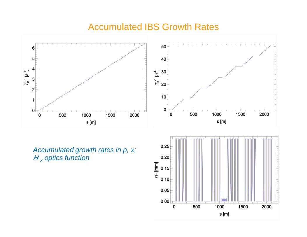
Accumulated IBS Growth Rates
Accumulated growth rates in p, x;Hx optics function

Correlation between Hx and d(1/Tp) in PEP-X
Hx and d(1/Tp) over one arc and one straight of PEP-X
Note the anti-correlation of the two functions in arc
With no correlation but “same” lattice parameters, 1/Tx would be twice as large
80Hx [mm]
dTp-1 [s-1]
Arc Straight

Emittance Dependence on Current
• With Tp-1 small, from simplified model can show that steady-state
emittances can be approximated by
with IA= 17 kA and a a constant
Steady-state emittances as function of bunch current in PEP-X.The dashed curve gives the analytical approximation.
analyticalformula

Dependence on Energy
Emittance ex= ey vs. energy for a round beam atnominal current (black) and at zero current (red).
(M. Borland)
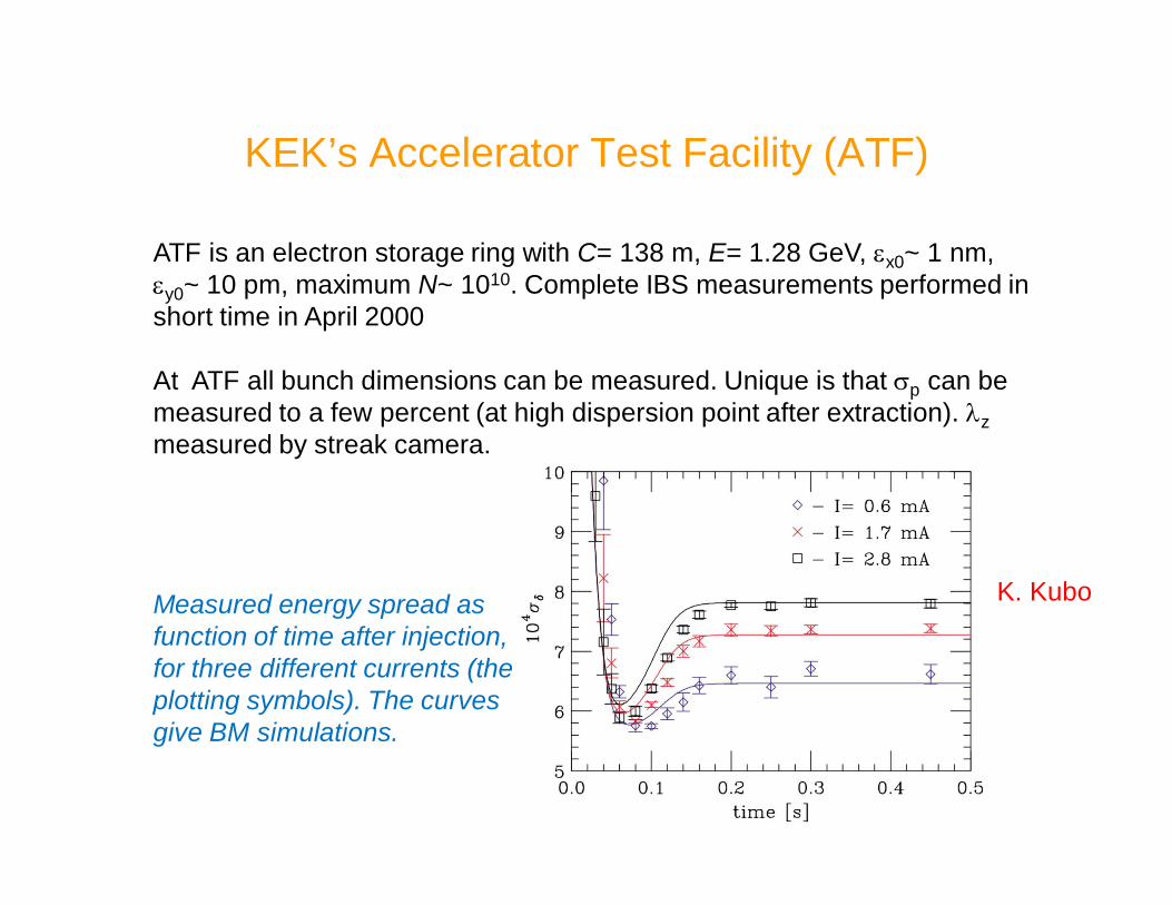
KEK’s Accelerator Test Facility (ATF)
ATF is an electron storage ring with C= 138 m, E= 1.28 GeV, ex0~ 1 nm,ey0~ 10 pm, maximum N~ 1010. Complete IBS measurements performed inshort time in April 2000
At ATF all bunch dimensions can be measured. Unique is that sp can bemeasured to a few percent (at high dispersion point after extraction). lzmeasured by streak camera.
Measured energy spread asfunction of time after injection,for three different currents (theplotting symbols). The curvesgive BM simulations.
K. Kubo

Other Measurements in Electron Machines
A more complete set of measurements was also performed at the ATF(simultaneous measurement of sp, sz, ex, ey) [K. Bane et al, PRST-AB 2002].Agreement with theory was good but not perfect. Now it is believed thatdiscrepancy was largely due to ey measurement errors
IBS measurements were performed at CESR-TA and seemed to agreereasonably well with theory, except for unaccounted growth in y [Ehrlichmanet al, IPAC 12, Blaser et al, IPAC 14]
Blaser et al,IPAC 14

More on IBS
F. Antoniou and Y. Pappaphilippou pointed out that the IBS models, BM,Piwinski, Bane, disagree (~10—20%), particularly when IBS is strong(TWIICE14)
Y. Pappaphilippou et al have managed to optimize the lattice of low emittancerings to significantly reduce IBS (IPAC13)

Touschek Lifetime
• Touschek effect concerns large, single Coulomb scattering events whereenergy transfer from transverse to longitudinal leads to immediate particle loss
• Number of particles in bunch decays as:
• Normally, for flat beams, use formula of Brueck
• Otherwise use general formula due to Piwinski. Inverse of Touschek lifetime:
• B1~ bx,y/ex,y=> where sx,y is large, 1/T is small because of exp(-tB1) factor inintegral. This factor is also reason 1/T becomes small at very small ex,y.

Momentum Acceptance in PEP-X
Momentum acceptance due to linear optics for PEP-X.The average value is dm= ±2.8%.
(Min-Huey Wang)

Touschek Lifetime Results
• Result for the IBS-determined steady-state beam sizes is: T= 11 hrs
Accumulation around the ring of the Touschek growth rate in PEP-X. Thegrowth is significant only in the arcs, where sx,y are small.

Dependence on Momentum Acceptance
Touschek lifetime T vs. (global) momentum acceptance parameter, dm (bluesymbols). The dashed curve gives the fit: T= 0.088(dm/0.01)5 hrs.

Touschek Lifetime vs Emittance
Emittance ex (= ey) and Touschek lifetime T vs wiggler length Lw (left plot), andT vs ex (right). These are results of self-consistent calculations including IBS.
As the length of wiggler Lw increases, the emittance decreases. In PEP-Xdesign Lw= 90 m, exnom= 11 pm (including IBS), Tnom= 11 hrs

Longitudinal Impedance Calculations for PEP-X• For PEP-X, without an actual vacuum chamber design available, wedeveloped a straw man design, inspired by objects in other machines, such asPEP-II
Sources include: RF cavities, BPM’s, wiggler transitions, undulatortransitions, resistive wall, coherent synchrotron radiation (CSR)
For the microwave instability, generate:(i) a pseudo-Green function wake representing the ring—to be used in
simulations (sz= .5 mm; nominal is 3 mm)
(ii) an impedance budget—to assess relative importance of contributors
People involved in 3D code development and impedance calculation includeL.-Q. Lee, C.-K. Ng, L. Wang, L. Xiao
This approach was successfully applied many years ago to the SLC dampingrings and DaFne, where drawings of the vacuum chamber components wereavailable [see e.g. Bane et al, HHH-2004 and references therein]
• Another approach is one or more Q= 1 resonators to represent ringimpedance (e.g. used for LEP); each resonator has two parameters wr, Rs

SLC Damping Ring Measurements (Old Ring)
K. Bane, R. Ruth,PAC89
Wake used in the simulations was obtained fromdrawings of vacuum chamber components

DaFne Bunch Length Measurements
Comparison of bunch lengthening simulations (green line) withmeasurements (symbols) for DaFne. The wake used in the simulationswas obtained from the drawings of vacuum chamber components
M. Zobov

Selected PEP-X Impedance Sources
Selected impedance objects included in our straw man PEP-X design.Note: the fundamental mode fields are shown in the RF cavity.
RFcavity
BPM
Pair of wiggler transitions
Pair of undulator transitions
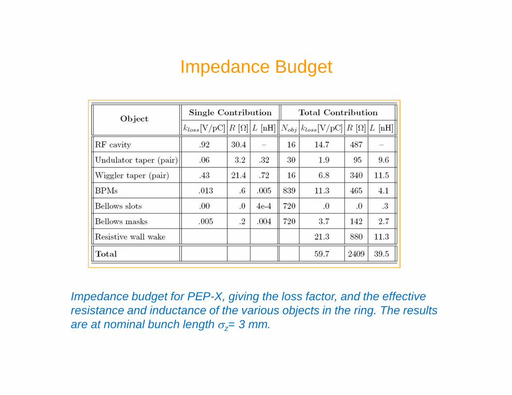
Impedance Budget
Impedance budget for PEP-X, giving the loss factor, and the effectiveresistance and inductance of the various objects in the ring. The resultsare at nominal bunch length sz= 3 mm.

Pseudo-Green Function Wake
Pseudo-Green functionwake representing the PEP-X ring: wake of a sz= .5 mmbunch
Haissinski solution, givingthe steady-state bunchshape. Bunch length is 25%above nominal length.
Front(G. Stupakov)

A Difficult Example:an Insertion Device
From “Impedance calculation for the NSLSII storage ring,” A. Blednykh
With the insertion gap becoming ever smaller, the insertion region becomes adominating part of the ring impedance*
Insertion transitions tend to be long, gradually tapered, and 3D => it is verychallenging to obtain the wakefield for a short bunch
*(especially true for vertical impedance)

Microwave Instability: Two Types
· Coasting beam analysis gives a (conservative) estimate of the threshold to themicrowave instability (Boussard, 1975):
with n= ck/w0 and |Z/n| taken at a representative frequency, e.g. at k= 1/sz
· In 1994 the SLC damping ring vacuum chambers were replaced with smootherchambers. Surprisingly the threshold dropped, from Nth= 3´1010 to 1.5--2.0´1010
Analysis showed that a new type of instability was found, which we call the weakinstability. Unlike the normal (strong) microwave instability, it is sensitive to thedamping time (Nth~ td
-1/2) and can be suppressed by Landau damping (see e.g.Oide, 1994)

Macro-particle Tracking (A. Renieri, 1976)

Vlasov-Fokker-Planck (VFP) Equation Solver
· Using macro-particle tracking with the pseudo-Green function, we findthat for PEP-X, the microwave threshold is very high (> 8 A)

· For short bunches (e.g. in low a mode) CSR can dominate the ring impedance,since strength ~sz
-4/3
· Wake of particles moving at speed c, on circle of radius r, between two metallicplates located at y= ±h was found by J. Murphy, et al.
· For a bunch, the normalized threshold current S is a function of normalizedshielding parameter P, with
· Used Vlasov-Fokker-Planck solver (a la Warnock) to find threshold current(S ) as function of P
Microwave Instability Due to Shielded CSR
test
drivingv =c
rheight 2h K. Bane, Y. Cai,
G. Stupakov,PRST-AB, 2010

For the CSR wake, threshold values of current S vs. shieldingparameter P. Symbols give simulation results.
· The dashed curve is Sth= 0.50 + 0.12 P. Result also agrees well withcoasting beam theory (for P not small), for which Sth~ P2/3 (Y. Cai,IPAC2011)
· We think dip at P~ 0.7 indicates a change from a strong to a weak instability
· For PEP-X, vacuum chamber is elliptical with axes (20.0, 12.5) mm andbending radius r= 100.8 m => P= 22.7 and Ith= 3.6 A, far above design I.
Threshold for Shielded CSR Impedance

Comparison with Measurement
Scaled values of measured bursting threshold at Metrology Light Source.Colors indicate measurement series within one a0 set.
M. Ries, et al,IPAC 12
· Reasonably good agreement at relatively longer bunch lengths and forlocation of dip. Note that simulations assumed simple phase space (not low a)
· Similarly good agreement for BESSY-II (P. Kuske), ANKA (M. Klein). Showsthat for short bunches CSR can dominate a ring impedance, and can besimply modeled

Other InstabilitiesTransverse Single Bunch (TMCI):
In light sources with regions of small aperture vacuum chambers, theresistive wall impedance is typically the dominant contributor. For aGaussian bunch the average kick in a round chamber of radius b
Single-bunch threshold can be approximated by [S. Krinsky]
For PEP-X, multi-bunch threshold Ith= MIbth= 1.8 A
PEP-X beam chamber types. The first three entries are Al, the last two Cu

Multi-bunch Transverse Instability:Including only the resistive wall wake, which often dominates the
multibunch transverse instability, the growth rate is given by [A. Wolski etal, 2006]
with
For PEP-X (ultimate) the growth rate is 1.4 ms-1 or 99 turns
Fast Ion Instability:Places requirements on vacuum pressure, gap in bunch train. Multi-
particle tracking shows that the instability is manageable (L. Wang)
At times the small aperture insertion devices dominate the transverseimpedance, with the geometric and resistive wall components being aboutequal in strength. Optimizing the 3D geometry of the transitions and thenestimating the instability threshold can be challenging (see e.g. Y.-C. Chae’stalk on APS insertion devices at TWIICE14)

Conclusions• In low emittance rings such as PEP-X “ultimate”, impedance effects tend notto be important since the current is quite low (200 mA)
• Our impedance calculations used a simplified, “straw dog” vacuum chambermodel. More precise calculations, when based on engineering drawings for areal machine, can change this conclusion, particularly when low apertureinsertion devices are present
• IBS sets the limit of current that can be stored in an ultimate ring. In PEP-Xwith round beams, IBS doubles the emittance to 11 pm at the design currentof 200 mA.
• The Touschek lifetime in ultimate PEP-X is quite large, 11 hrs, but it is a verysensitive function of the momentum acceptance
• How to run a machine with a round beam needs serious study. The choicewill affect the IBS and Touschek effect