Embed Size (px)
Citation preview

Emittance and Emittance Measurements
S. Bernal
USPAS 08
U. of Maryland, College Park
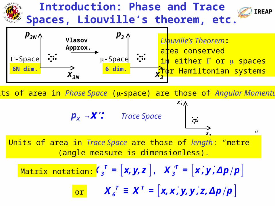
IREAPIREAPIntroduction: Phase and Trace Spaces, Liouville’s theorem, etc.
Liouville’s Theorem: area conserved in either or spaces for Hamiltonian systems
Units of area in Phase Space (space) are those of Angular Momentum.
Vlasov Approx.
6N dim.
3Np
3Nx
-Space
3p
3x
-Space
6 dim.
Units of area in Trace Space are those of length: “metre” (angle measure is dimensionless).
pX → x : Trace Space
3x
3x
,
T3X = x,y,z
T
3X = x,y,Δp pMatrix notation:
T T6X ≡ X = x,x,y,y,z,Δp por
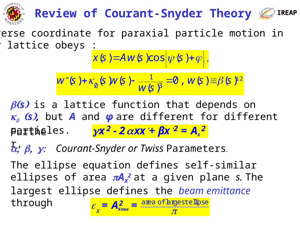
IREAPIREAPReview of Courant-Snyder Theory
sis a lattice function that depends on s, but A and φ are different for different particles.
Transverse coordinate for paraxial particle motion in linear lattice obeys :
,( ) ( )cos ( )x s Aw s s
1 23
10
( ) ( ) ( ) 0 , ( ) ( )( )
w s s w s w s sw s
Courant-Snyder or Twiss Parameters.
X2 2 2x -2 xx +βx =AFurther,
The ellipse equation defines self-similar ellipses of area AX2
at a given plane s. The largest ellipse defines the beam emittance through
area of largest ellipsex Xmax
2=A =
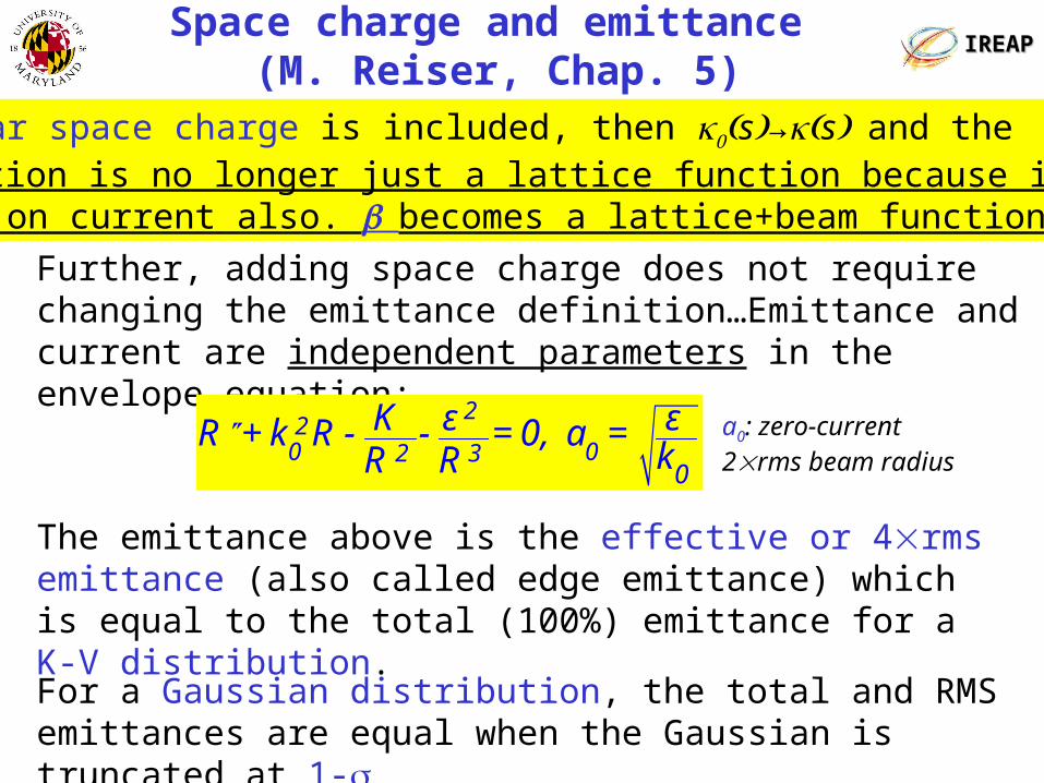
IREAPIREAPSpace charge and emittance
(M. Reiser, Chap. 5)If linear space charge is included, then s→sand the function is no longer just a lattice function because it now depends on current also. becomes a lattice+beam function.
The emittance above is the effective or 4rms emittance (also called edge emittance) which is equal to the total (100%) emittance for a K-V distribution.
Further, adding space charge does not require changing the emittance definition…Emittance and current are independent parameters in the envelope equation:
For a Gaussian distribution, the total and RMS emittances are equal when the Gaussian is truncated at 1-
2
20 02 3
0
K ε εR +k R - - =0, a =kR R
a0: zero-current 2rms beam radius

IREAPIREAPRMS Emittance and Envelope Equation(Pat G. O’Shea)
2
2
xxx xx xxa = , a =- a + + ,
a a a a
2RMSa≡x = x , 2x =-k x,Linear system: Define:
2 2 2
2
x k xxx=- a + - ,
a a a2 2
23
xxx=- + -k a,
a a
2 2 2 23
1a =- xx - x x -k a,
a
2
2 RMS3
εa +k a- =0,
a 22 2
RMSε = x x - xx
IREAPIREAP Emittance Growth (M. Reiser, Chap. 6)
X’
x
X’
x
X’
x
X’
x
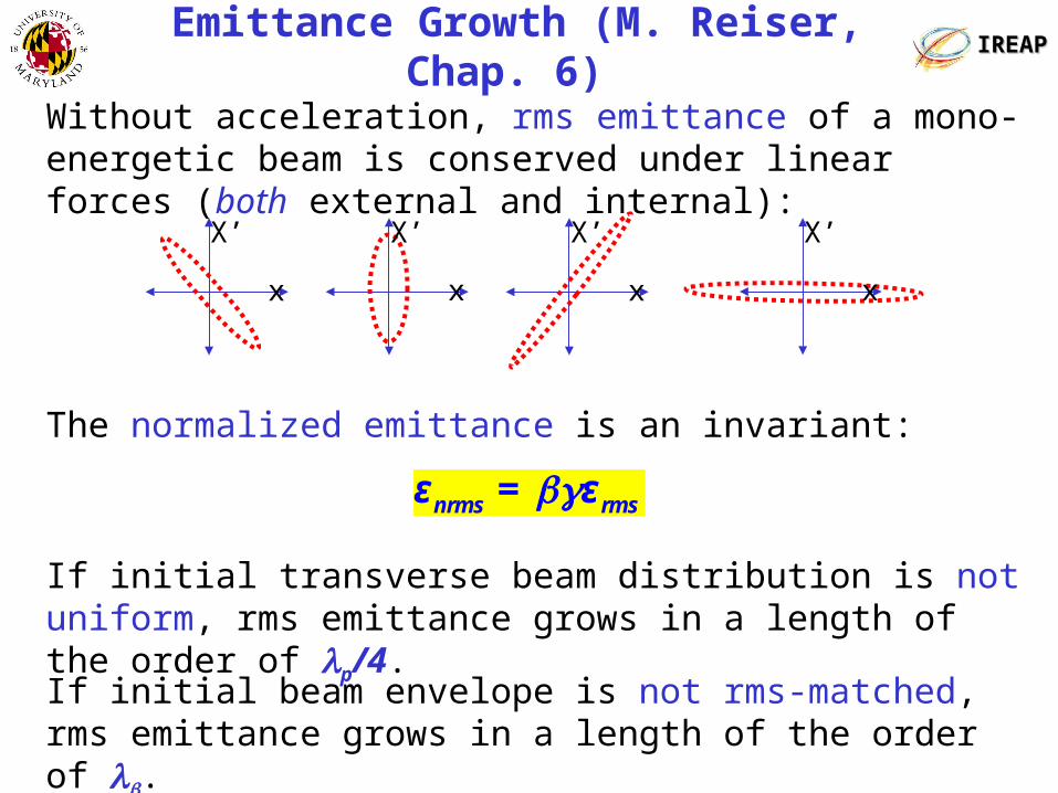
Without acceleration, rms emittance of a mono-energetic beam is conserved under linear forces (both external and internal):
nrms rmsε = ε
The normalized emittance is an invariant:
If initial transverse beam distribution is not uniform, rms emittance grows in a length of the order of p/4.
If initial beam envelope is not rms-matched, rms emittance grows in a length of the order of .

IREAPIREAPLaminar and Turbulent Flows
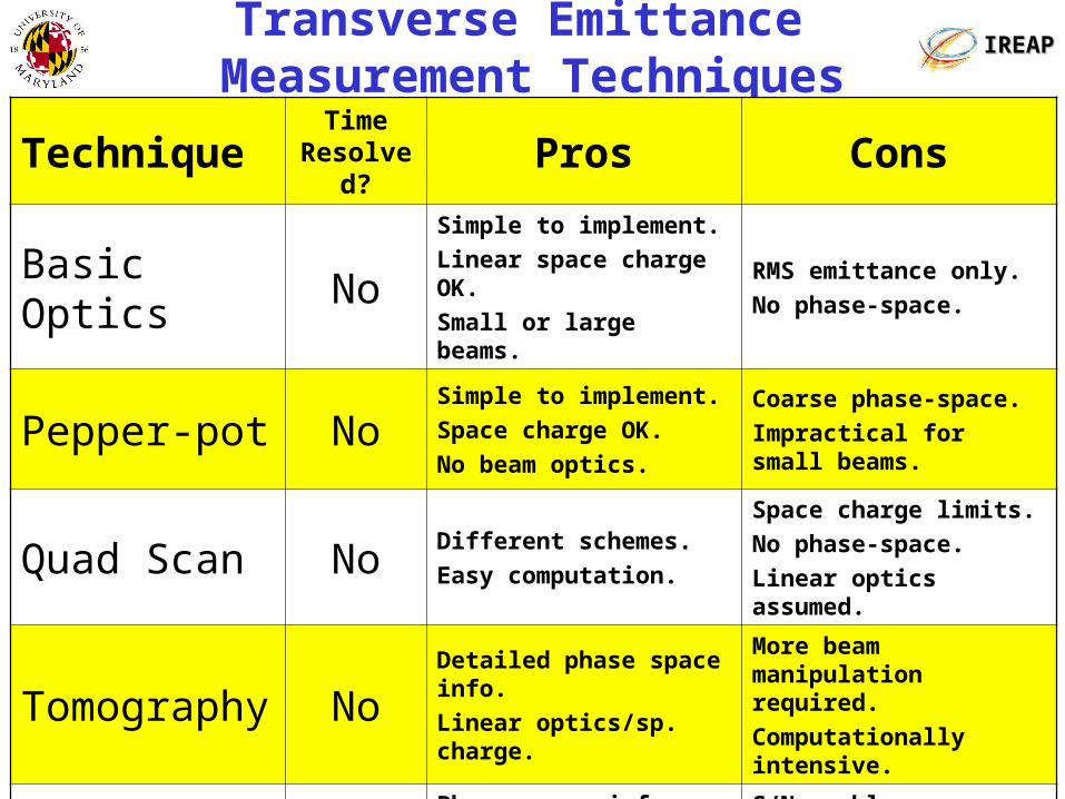
Transverse Emittance Measurement Techniques
IREAPIREAP
TechniqueTime
Resolved?
Pros Cons
Basic Optics NoSimple to implement.
Linear space charge OK.
Small or large beams.
RMS emittance only.
No phase-space.
Pepper-pot NoSimple to implement.
Space charge OK.
No beam optics.
Coarse phase-space.
Impractical for small beams.
Quad Scan NoDifferent schemes.
Easy computation.
Space charge limits.
No phase-space.
Linear optics assumed.
Tomography NoDetailed phase space info.
Linear optics/sp. charge.
More beam manipulation required.
Computationally intensive.
Slit-Wire YesPhase space info.
Integrated or t-resolved.
Space charge OK.
S/N problems.
Hard to implement.
Comp. intensive.
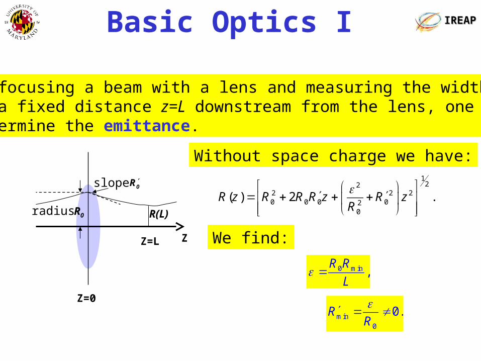
Basic Optics I IREAPIREAP
Without space charge we have:
122
2 2 20 0 0 02
0
( ) 2 .R z R R R z R zR
We find:
0 min ,R R
L
min0
0.RR
By focusing a beam with a lens and measuring the width at a fixed distance z=L downstream from the lens, one candetermine the emittance.
R0
0Rslope
R(L)radius
Z=L
Z=0
Z
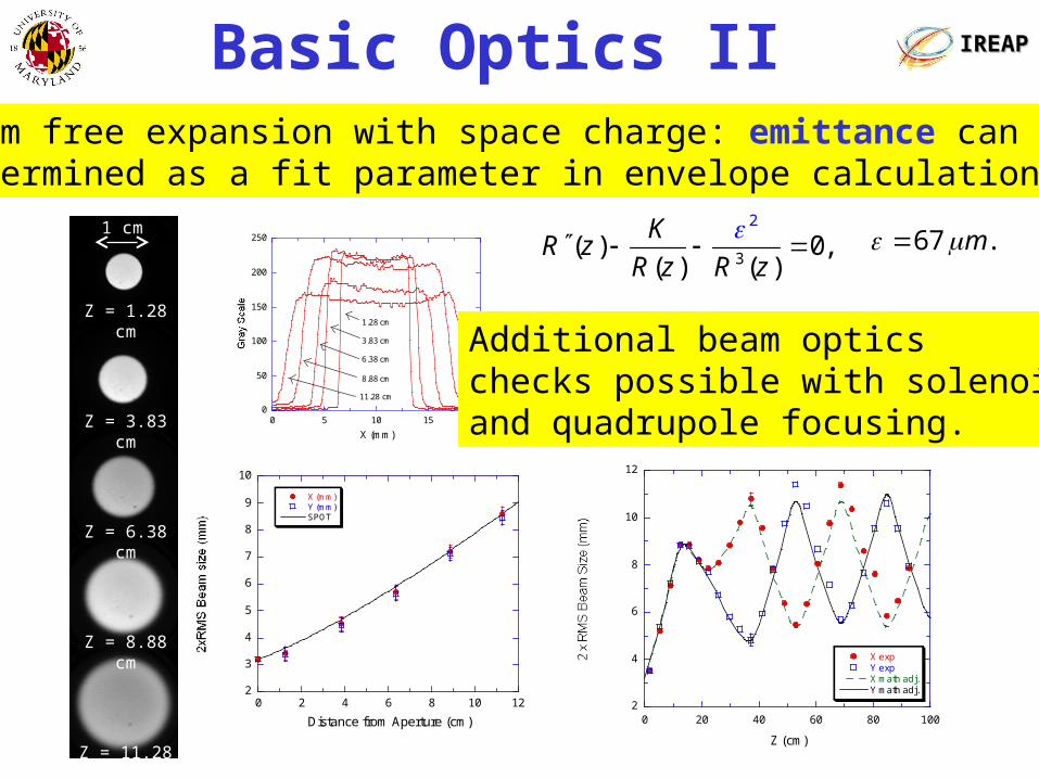
Basic Optics II IREAPIREAP
67 .m1 cm
Z = 1.28 cm
Z = 3.83 cm
Z = 6.38 cm
Z = 8.88 cm
Z = 11.28 cm
0
50
100
150
200
250
0 5 10 15 20
X (mm)
1.28 cm
3.83 cm
6.38 cm
8.88 cm
11.28 cm
2
3
4
5
6
7
8
9
10
0 2 4 6 8 10 12
X (mm)Y (mm)SPOT
Distance from Aperture (cm)
Beam free expansion with space charge: emittance can be determined as a fit parameter in envelope calculation.
3
2
( ) 0,( ) ( )
KR z
R z R z
Additional beam optics checks possible with solenoid and quadrupole focusing.
2
4
6
8
10
12
0 20 40 60 80 100
X expY expX math adj.Y math adj.
Z (cm)
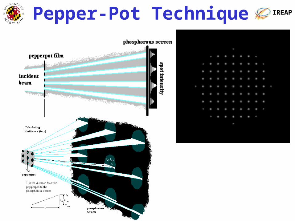
IREAPIREAPPepper-Pot Technique

IREAPIREAP
(c)
10keV, 100 mA, 700 experiment
X = 67 μm, Y = 55 μm
(b)
0.166 mm/pixel
(a)
Pepper-Pot Technique

IREAPIREAP
Calculating emittance and plotting phase space:
Pepper-Pot Technique
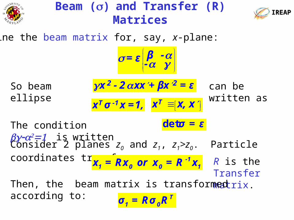
IREAPIREAPBeam ()and Transfer (R) Matrices
Define the beam matrix for, say, x-plane:
Consider 2 planes z0 and z1, z1>z0. Particle coordinates transform as:
β -=ε -
So beam ellipse can be written as 2 2x -2 xx +βx =ε T -1x σ x=1, Tx x, x
-11 0 0 1x =Rx or x =R x R is the
Transfer matrix.
The condition iswritten
σ =εdet
Then, the beam matrix is transformed according to:T
1 0σ =Rσ R

IREAPIREAPQuadrupole Scan
2 22
2 21 1 1quad 2 quad 3 2
1 1x =A -2AB +( C+AB ) ,ff
=mI -2mmI +( m +mm ) ,
1 .he heqeff
e
qg ll I
m cf
2ACε= ,d
2A 1 A 1+= B+ , = , = .dC C
IC2
Solenoid
IC1Q2
d
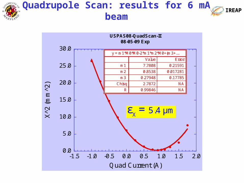
IREAPIREAPQuadrupole Scan: results for 6 mA beam
0.0
5.0
10.0
15.0
20.0
25.0
30.0
-1.5 -1.0 -0.5 0.0 0.5 1.0 1.5 2.0
USPAS08-QuadScan-II08-05-09 Exp
X^2 (mm^2)
X^2
(m
m^2
)
Quad Current (A)
y = m1*M0*M0-2*m1*m2*M0+(m3+...
ErrorValue
0.215917.7808m1
0.0172810.8538m2
0.177850.27948m3
NA2.7872Chisq
NA0.99846R
X
5.4 μmε =
1. Martin Reiser, Theory and Design of Charged-Particle Beams, 2nd Ed,
Secs. 3.8.2, 5.3.4 (see Table 5.1) and Chapter 6.
2 D. A. Edwards and M. J. Syphers, An Introduction to the Physics of High
Energy Accelerators, Sec. 3.2.4 (see Table 3.1).
3 Claude Lejeune and Jean Aubert, Emittance and Brightness: Definitions
and Measurements, Advances in Electronics and Electron Physics,
Supplement 13A, Academic Press (1980).
4 Andrew M. Sessler, Am. J. Phys. 60 (8), 760 (1992); J. D. Lawson, “The
Emittance Concept”, in High Brightness Beams for Accelerator
Applications, AIP Conf. Proc. No. 253; M.J. Rhee, Phys. Fluids 29 (1986).
5. Michiko G. Minty and Frank Zimmermann, Beam Techniques, Beam
Control and Manipulation, USPAS, 1999.
6. S. G. Anderson, J. B. Rosenzweig, G. P. LeSage, and
J. K. Crane, “Space-charge effects in high brightness electron
beam emittance measurements”, PRST-AB, 5, 014201 (2002).
7. Manuals to computer codes like TRACE3D, TRANSPORT, etc. .
References

IREAPIREAP
Backup Slides

Detectors IREAPIREAP
Type Characteristics
Phosphor ScreenExample: P43 phosphor (green output). Fairly linear. Inexpensive but delicate. Slow time response (up to ms tails.) Used in combination with CCD or MCP/CCD.
Fast Phosphor Screen
Example: P22 phosphor (blue output). Fairly linear. Delicate and expensive. Response time in the ns range.
Used in combination with CCD or MCP/CCD.
OTR ScreenAny mirrored surface. OTR maps beam in real time (fs response) with high spatial resolution. Good for any beam energy. Used in combination with PMT or CCD cameras. Low current beams require long int. times.
Standard CCDStandard, inexpensive (8-bit.) Can be intensified for extra sensitivity. Slow response.
Cooled CCD higher sensitivity + 16-bit.
Gated Camera0.1 ns time response possible. Expensive.
Streak cameras: pico-second time resolution.

24 mA, 10 keV, χ=0.9
Location S (m) X (µm) Y (µm)
Aperture Plate 0 1.50±0.25 1.5±0.25
After 1/4 turn 3.8 1.50 1.80
After 1/2 turn 7.0 2.10 1.40
After 2/3 turn 9.0 1.60 2.50
IREAPIREAPEmittance (rms. Norm.) in DC Injection Exps.