Embed Size (px)
Citation preview

© 2016 The Korean Society of Rheology and Springer 355
Korea-Australia Rheology Journal, 28(4), 355-379 (November 2016)DOI: 10.1007/s13367-016-0035-2
www.springer.com/13367
pISSN 1226-119X eISSN 2093-7660
Advancement in energy harvesting magneto-rheological fluid damper: A review
Raju Ahamed1,*, Md Meftahul Ferdaus
2 and Yancheng Li
3
1Department of Mechatronics Engineering, International Islamic University Malaysia, Kuala Lumpur 53100, Malaysia2School of Engineering and IT, University of New South Wales, Sydney NSW 2052, Australia
3Centre for Built Infrastructure Research, University of Technology Sydney, Sydney NSW 2007, Australia
(Received May 22, 2016; final revision received August 18, 2016; accepted September 6, 2016)
In this paper, a comprehensive review of the present literature on energy generated magnetorheological(MR) fluid based damper, modeling and applications of the MR damper are presented. The review startswith an introduction of the basic of MR fluid and their different modes, consequences with different typesof MR fluids based devices, and their relevant applications. Besides, various forms of MR damper and itsapplications are presented. Following this, the modeling of the MR fluids and the modeling of the MR fluidbased damper are deliberated according to arrangement and configurations. Finally, the review ends withthe design and advancement issues, performance analysis matters, and analytical modeling of energy gen-erated magnetorheological fluid damper systems.
Keywords: energy generation, MR damper, MR fluid, models, design
1. Introduction
At present, magneto-rheological fluid based dampers are
promising for vehicle suspension system. With an applied
magnetic field, MR fluid can change into the semi-solid
state from the liquid state within a few milliseconds (Chen
and Liao, 2010; Kordonsky, 1993a). By using this prin-
ciple, the MR damper can create controllable damping
force. Generally, the combination of high-performance
MR fluid application systems needs several factors such
as materials properties, viscosity, temperature etc. (Choi et
al., 2016). Sensors are very useful for measuring the
dynamic response as well as to ensure full use of the con-
trollable damping characteristics (Kaluvan et al., 2016). It
includes correlative dislocation or velocity with MR
damper diagonally and its installation and maintenance
system could be complex. Moreover, there are various
types of developed models for the characteristics of MR
dampers. With regards to the method of modelling, the
models are classified as parametric (Şahin et al., 2010;
Wang and Liao, 2011) and non-parametric dynamic mod-
els (Choi et al., 2001; Ehrgott and Masri, 1992; Jin et al.,
2005; Kim et al., 2008; Song et al., 2005; Song et al.,
2007). By considering the characteristics shown by the
established models, they can be further classified as qua-
sistatic models (Chooi and Oyadiji, 2008; Hong et al.,
2008) and dynamic models. Considering the reversibility
of the established models, they are classified as dynamic
models (Wang and Liao, 2005; 2011) and inverse dynamic
models (Tsang et al., 2006).
Furthermore, MR damper vibration and shock create
mechanical energy which is possible to use as a power
source, since a huge amount of this mechanical energy is
lost during daily usage of an automobile in irregular sur-
face of roads. It is concluded that the wasted energy by
vibration is caused by highway roughness, car speed, sus-
pension rigid, and damping coefficient and it has reported
that the total energy dissipation of four dampers of traveler
vehicle reached 200 W when going on a haggard highway
at more or less 13.4 ms−1 (Fodor and Redfield, 1993; Segel
and Lu, 1982; Velinsky and White, 1980). There would be
no need of external power supply by transforming this
wasted energy into electrical energy (Lesieutre et al., 2004;
Scruggs and Iwan, 2003). Further there will be no require-
ment for extra sensors when dynamic responses are pos-
sible to measure, with the exception of an addition sensor.
This self-sensing and self-powered device is an energy
saving technology with no environmental effects. In addi-
tion, the reliability of the total MR damper system will be
improved with the help of this technology. The weight and
size would definitely be reduced, which is a huge benefit
of this system with its design simplicity and low conser-
vation budget. In some life threatening situation like earth-
quakes this self-powered MR damper technology would
works perfectly since there are chances of cutting off the
power supply.
This concept of self-sensing and self-powered damper
has been used to develop energy-saving smart MR damper.
Many researchers are trying to develop and improve the
self-powered technology. Nakano et al. (2003) observed
that producing current in the reproduction process is better
to fulfill the power demand in the dampers. Hsu (1996)
has measured the total regenerative power, which has
reached 100 W when going on the road at 16 ms−1. More-
over, Dong (2015) measured in D grade road the gener-
ated energy is about 45 W when velocity is around 0.6693*Corresponding author; E-mail: [email protected]
Review
Raju Ahamed, Md Meftahul Ferdaus and Yancheng Li
356 Korea-Australia Rheology J., 28(4), 2016
ms−1. Energy dissipation in vehicle’s passive and active
suspension system is analyzed by Yu et al. (2005). Con-
cerning with the former research on self-sensing control-
lable dampers, an integrated magneto astrictive position
sensor was developed for MR dampers by Russell (2001).
It was difficult to develop commercially due to its com-
plicated structure, proper manufacturing action and costly
magneto astrictive materials. Nehl et al. (1996) proposed
an integrated self-energizing comparative velocity sensor
which is impossible to center within MR dampers. The
sensor’s coil is wounded on MR damper’s dust tube result-
ing performance degradation of the sensor and limit their
usage in MR dampers. Wang et al. introduced an electro-
magnetic induction based MR damper and compact with
a similar displacement sensor too (Wang and Bai, 2011;
Wang and Wang, 2009; Wang et al., 2010). This sensing
process consists of complicated circuits for signal process-
ing. Or et al. (2008) presented an MRD including piezo-
electric based force sensor. Some research have been done
previously on MR damper’s capability to generate power.
Cho et al. (2005) presented an energy harvested MR damper
that consists of an electromagnetic induction (EMI) device
in order to mitigate vibrations from suspension. It gives a
technological strategy for vibration control with power
generation ability, where the EMI converts the vibration
energy into electrical energy. Choi and Werely (2009)
have asserted some corresponding researches. They stud-
ied the obligation and usefulness of self-powered MR
damper and used a spring-mass electromagnetic induction
device. The generated power is supplied to MR damper,
which eliminates the necessity of using additional sensors
in their former two works. In addition, Sapiński (2010)
demonstrated a linear MR damper’s power generator called
electromagnetic power generator. Mainly the performance
and construction of the generator were focused in their
research. Ahamed et al. (2016) proposed a design of energy
generated MR damper for vehicle suspension system. The
magnet and coil arrangement are used for generation of
energy from vehicle vibration. In the former research on
self-powered MR dampers with sensing ability have
revealed various expectant results, however a few research
has been accomplished on MR damper that combines the
self-powered and self-sensing ability into one device.
Chen and Liao (2012a) have proposed a MR damper with
self-powered and self-sensing capability. Their design is
developed for double ended MR damper and applicable to
civil structures. Ferdaus et al. (2013) proposed a self-pow-
ered MR damper model which has self-sensing ability.
Permanent magnet, coil, and spring arrangement are in
this proposed model to generate energy.
With the purpose to identify the achievement of research
and improvement of self-powered MR damper, an inclu-
sive review is required. This paper offers the survey of
current improvement and advancement of self-powered
MR regarding different improvements of structural and
designs besides modeling techniques considered in each
improvement.
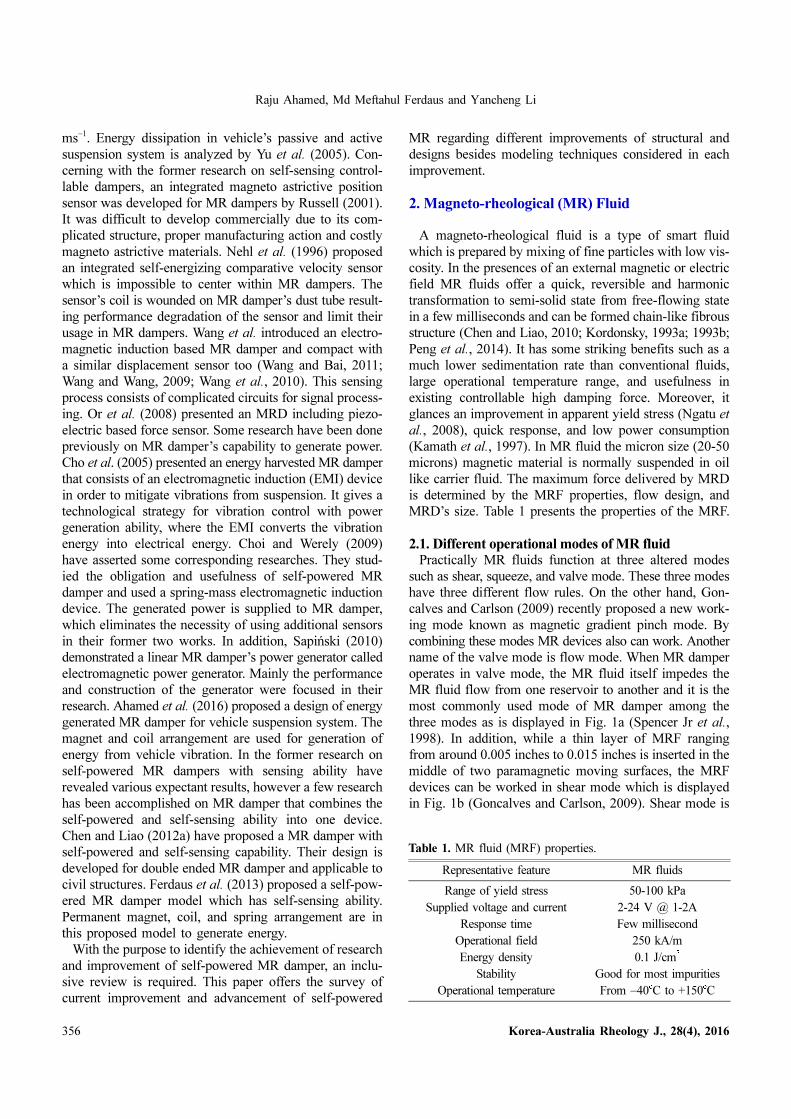
2. Magneto-rheological (MR) Fluid
A magneto-rheological fluid is a type of smart fluid
which is prepared by mixing of fine particles with low vis-
cosity. In the presences of an external magnetic or electric
field MR fluids offer a quick, reversible and harmonic
transformation to semi-solid state from free-flowing state
in a few milliseconds and can be formed chain-like fibrous
structure (Chen and Liao, 2010; Kordonsky, 1993a; 1993b;
Peng et al., 2014). It has some striking benefits such as a
much lower sedimentation rate than conventional fluids,
large operational temperature range, and usefulness in
existing controllable high damping force. Moreover, it
glances an improvement in apparent yield stress (Ngatu et
al., 2008), quick response, and low power consumption
(Kamath et al., 1997). In MR fluid the micron size (20-50
microns) magnetic material is normally suspended in oil
like carrier fluid. The maximum force delivered by MRD
is determined by the MRF properties, flow design, and
MRD’s size. Table 1 presents the properties of the MRF.
2.1. Different operational modes of MR fluidPractically MR fluids function at three altered modes
such as shear, squeeze, and valve mode. These three modes
have three different flow rules. On the other hand, Gon-
calves and Carlson (2009) recently proposed a new work-
ing mode known as magnetic gradient pinch mode. By
combining these modes MR devices also can work. Another
name of the valve mode is flow mode. When MR damper
operates in valve mode, the MR fluid itself impedes the
MR fluid flow from one reservoir to another and it is the
most commonly used mode of MR damper among the
three modes as is displayed in Fig. 1a (Spencer Jr et al.,
1998). In addition, while a thin layer of MRF ranging
from around 0.005 inches to 0.015 inches is inserted in the
middle of two paramagnetic moving surfaces, the MRF
devices can be worked in shear mode which is displayed
in Fig. 1b (Goncalves and Carlson, 2009). Shear mode is
Table 1. MR fluid (MRF) properties.
Representative feature MR fluids
Range of yield stress 50-100 kPaSupplied voltage and current 2-24 V @ 1-2A
Response time Few millisecondOperational field 250 kA/mEnergy density 0.1 J/cm3
Stability Good for most impuritiesOperational temperature From −40oC to +150oC

Advancement in energy harvesting magneto-rheological fluid damper: A review
Korea-Australia Rheology J., 28(4), 2016 357
primarily suitable for dampers those can provide small
forces or in compact clutches and brakes. When an MRF
thin film of a width of 0.02 inch is inserted between pole
surface, the MRF devices can operate by using squeeze
mode presented in Fig. 1c (Guglielmino et al., 2008).
Moreover, the main idea of magnetic gradient pinch
mode is like the flow mode, however, it has numerous
arrangement of the magnetic circuit. Figure 1d shows the
magnetic gradient pinch mode with magnetic poles, which
are organized axially along with flow direction and divided
by nonmagnetic substantial. This types of poles organiza-
tion of the magnetic gradient pinch mode can produce
elliptical magnetic fibrils that would resist the passing of
MRF in valve gap. Among all attributes, the special attri-
bute of this mode is the gradient would knowingly be
increased proportionally with the applied magnetic field in
the middle of pressure-velocity affiliation (Goncalves and
Carlson, 2009). It is exceptional, under any magnetic field
asset alterations the gradient tends to keep on constant
since in the ordinary flow mode. Another benefit is the
probability of utilizing MRF with rougher particles of
ranges like 100 μm, since a bigger orifice is achievable to
be utilized with this mode (Goncalves and Carlson, 2009).
2.2. Various models for MR fluids For improvement of the MRF devices, MR fluids model
is an important part. All MR fluid models have shown in
Table 2. At first, in 1969 Bingham introduced flow equa-
tion which is known as Bingham flow equations (Gon-
calves et al., 2006). After this work, modeling of MR
fluids acknowledged significant consideration.
Furthermore, the present models are very accurate. To
characterize the MR fluids different nonlinear models
have been used such as Bingham plastic model (Carlson
and Jolly, 2000; Kato and Phillips, 1969) the Biviscous
model (Stanway et al., 1996) and the Herschel-Bulkley
model (Choi et al., 2005; Wang and Gordaninejad, 1999).
MR fluid’s Bingham model contains a moveable and
accurately rigid plastic material that is associated with the
corresponding Newtonian material. The equations of this
model have been exposed in Table 2. Figure 2 shows the
Bingham plastic model to portray the yield stress’s per-
formance field-dependency. Moreover, to operate the MR
devices in squeeze flow mode, the shear stress equation of
the Bingham plastic model is widespread interested in the
Fig. 1. (Color online) (a) Valve mode (Yang et al., 2002), (b)direct shear mode (Zhu et al., 2012), (c) squeeze mode (Gug-lielmino et al., 2008), and (d) magnetic gradient mode (Gon-calves and Carlson, 2009).
Table 2. MR fluid models.
Model name Equation Symbols References
Bingham Plastic Model
τ = τy(H)sgn( ) + η ,τ > τy τ = G ,τ < τy
H = magnitude of applied field= fluid shear strain rate
sgn(·) = signum functionη = plastic viscosity (at zero field)τ = shear stressτy = yield shear stressG = complex modulus of the material
(Jolly et al., 1998; Wang and Liao, 2011; Weiss and Duclos, 1994)
Biviscous Model
ηr and η = the elastic and viscous fluid properties
(Stanway et al., 1996; Wang and Liao, 2011; Wilson and Thomas, 2006)
Herschel-Bulkley Model
K and m = the fluid parameters(Choi et al., 2005; Wang and Liao,
2011; Wang and Gordaninejad, 2007)
γ· γ·
γ·
γ·
τ = τy H( ) + ηγ· , τ > τ1
ηrγ· τ < τ2
⎩⎪⎨⎪⎧
τy H( ) = τ1 1η
ηr
------–⎝ ⎠⎛ ⎞
τ = τy H( ) + K γ·1
m----
⎝ ⎠⎜ ⎟⎛ ⎞
sgn γ·( )

Raju Ahamed, Md Meftahul Ferdaus and Yancheng Li
358 Korea-Australia Rheology J., 28(4), 2016
biviscous relationship as shown in Table 2. Figure 3 dis-
plays the Biviscous model.
Conversely, the model presented in Fig. 2 is a substitute
for the Bingham plastic model. The post-yield and shear
thinning behavior of the MRF is explained usually by this
model. The equation of this model is shown in Table 2.
2.3. MR devicesAs MR fluids’ properties are controllable by applied
magnetics field’s strength, they are suitable for the require-
ment of variable force applications. The commercializa-
tion of MR technology started in 1995. During the past
decade’s commercially available products (or near com-
mercialization) have been developed rapidly for example
MR fluids used. Different MR devices and their applica-
tion are displayed in Table 3.
3. MR Damper and Its Application
MR damper works as a vibration isolator, which is loaded
with MRF and controlled by an electromagnetic field. It
follows the semi-active control strategies. At present, man-
ufacturers are exposing more attention to the MR dampers.
The development of MR fluids by Lord Corporation is an
example and they are currently manufacturing MR truck
seat dampers (Poynor, 2001), which are possibly one of
the most effective marketable MR dampers to date. The
applications of MR damper are shown in Table 4.
Fig. 2. Bingham model and Herschel-Bulkley model (Koo et al.,2006).
Fig. 3. Idealized biviscous constitutive relationship (Stanway et
al., 1996; Wang and Liao, 2011).
Table 3. MR damper devices and applications.
MR devices Figure No. Application References
MR damper 4Heavy truck, knee prosthetics of limbs,
humanoid robot, haptic devices, motion master
(Carlson and Chrzan, 1994; Yao et al., 2002)
Brakes and clutches 5, 6, 7, 8Aerospace, Industry, haptic device,
aerobic exercise machine(Benetti and Dragoni, 2006;
Lee et al., 1999; Nguyen et al., 2016)
Polishing devices 9Ocular glasses, ceramics, plastics, and few nonmagnetic materials
(Wang et al., 2013)
Hydraulic valves 10 Actuator, converters(Kordonsky, 1993b;
Kordonsky et al., 1995)
Seals 11 Rotary shaft (Kordonski and Gorodkin, 1996)
Composite structures 12, 13Plates, panels, beams and bars,
or constructions(Weiss et al., 1996)
Pneumatic actuator motion control systems
14, 15, 16Set in parallel along with a linear
resistance component(Wang and Meng, 2001)
Flexible fixtures 17, 18 Turbine blades (Tang et al., 1999)
MR valves 19 Actuator (Guo et al., 2003)
MR device based MR elastomers
20, 21MRE force sensors, automotive bushings
and engine mounts(Sun et al., 2016)

Advancement in energy harvesting magneto-rheological fluid damper: A review
Korea-Australia Rheology J., 28(4), 2016 359
4. Types of MR Damper
According to the design and configuration of MR damp-
ers, basically MR damper can be divided into three clas-
sifications, monotube, twin tube, and double-ended MR
damper along with MR- Hydraulic hybrid damper. Mono-
tube MR damper consists of only one tube or reservoir is
known as Monotube MR damper as presented in Fig. 22.
Table 4. Application of MR dampers.
Application References
Automobile (Du et al., 2005; Dutta and Choi, 2016; Dutta et al., 2016; Lee et al., 2006a; Yang et al., 2016; Yao et al., 2002)
Railway vehicle (Ha et al., 2008; Lau and Liao, 2005; Liao and Wang, 2003; Oh et al., 2016; Wang and Liao, 2009)
Civil structural applications
(Jung et al., 2004; Kciuk and Turczyn, 2006; Lee et al., 2006b; Medina, 2016; Ritchey, 2003; Symans and Constantinou, 1999; Yang et al., 2004)
Mechanical structure (Sapiński, 2009; Wang and Meng, 2001)
Social application (Case et al., 2011; 2013; Herr et al., 2006; Kim and Oh, 2001; Klingenberg, 2001)
Helicopter leg (Marathe et al., 1998)
Household application (Chrzan and Carlson, 2001; Spelta et al., 2009)
Military equipment (Ha et al., 2013; Sedlák and Kuffová, 2015)
Fig. 4. (Color online) MR damper (Truong and Ahn, 2012).
Fig. 5. Rotary MR fluid brake (Carlson and Jolly, 2000).
Fig. 6. (Color online) MR brake (Karakoc et al., 2008).
Fig. 7. (Color online) The optimally designed MR clutch(Moghani and Kermani, 2016).
Fig. 8. (Color online) MR clutch (Nguyen et al., 2016).

Raju Ahamed, Md Meftahul Ferdaus and Yancheng Li
360 Korea-Australia Rheology J., 28(4), 2016
Among these three types it is most commonly used due to
its compact size and ability to install in any location. In
addition, an MR damper that contains two fluid reservoirs
is called twin tube MR damper where one tube is inside of
the other, as displayed in Fig. 23.
Moreover, the MR damper in which two piston rods of
the same diameter enter the reservoir from both ends of
the damper is known as double ended MR damper as dis-
played in Fig. 24 (a section view). It is a type of damper
where the volume is unchanged due to piston’s respective
movement and as a result, the accumulator mechanism is
absent here. Some common application of this damper is
in gun recoil (Ahmadian and Poynor, 2001), bicycle
(Ahmadian et al., 1999), building sway motion controlling
due to heavy wind flow or earthquakes etc.
However, the most recent category of MR damper is
Fig. 9. (Color online) (a) 3D CAD view of polishing experi-mental setup and (b) main hardware with different components(Wang et al., 2013).
Fig. 10. MR hydraulic valve (Yoo and Wereley, 2004).
Fig. 11. MR seal (1) MR fluid, (2) poles, (3) permanent magnet,and (4) magnetic shaft (Kordonski and Gorodkin, 1996).
Fig. 12. (Color online) MR beam configurations test rig withvertical (Lara-Prieto et al., 2009).
Fig. 13. (Color online) MR beam configurations test rig withhorizontal (Lara-Prieto et al., 2009).
Fig. 14. (Color online) Position-feedback MR actuator (Liu et
al., 2006).
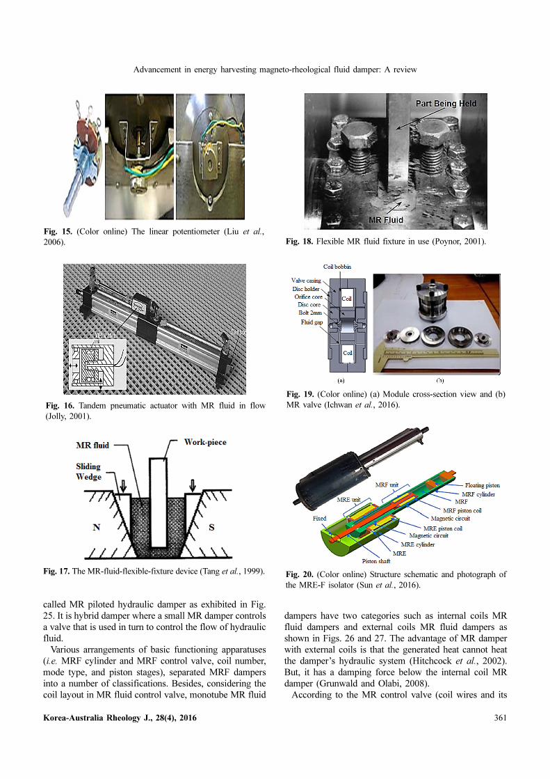
Advancement in energy harvesting magneto-rheological fluid damper: A review
Korea-Australia Rheology J., 28(4), 2016 361
called MR piloted hydraulic damper as exhibited in Fig.
25. It is hybrid damper where a small MR damper controls
a valve that is used in turn to control the flow of hydraulic
fluid.
Various arrangements of basic functioning apparatuses
(i.e. MRF cylinder and MRF control valve, coil number,
mode type, and piston stages), separated MRF dampers
into a number of classifications. Besides, considering the
coil layout in MR fluid control valve, monotube MR fluid
dampers have two categories such as internal coils MR
fluid dampers and external coils MR fluid dampers as
shown in Figs. 26 and 27. The advantage of MR damper
with external coils is that the generated heat cannot heat
the damper’s hydraulic system (Hitchcock et al., 2002).
But, it has a damping force below the internal coil MR
damper (Grunwald and Olabi, 2008).
According to the MR control valve (coil wires and its
Fig. 15. (Color online) The linear potentiometer (Liu et al.,2006).
Fig. 16. Tandem pneumatic actuator with MR fluid in flow(Jolly, 2001).
Fig. 17. The MR-fluid-flexible-fixture device (Tang et al., 1999).
Fig. 18. Flexible MR fluid fixture in use (Poynor, 2001).
Fig. 19. (Color online) (a) Module cross-section view and (b)MR valve (Ichwan et al., 2016).
Fig. 20. (Color online) Structure schematic and photograph ofthe MRE-F isolator (Sun et al., 2016).

Raju Ahamed, Md Meftahul Ferdaus and Yancheng Li
362 Korea-Australia Rheology J., 28(4), 2016
separation from MRFs) placement inside the moving pis-
ton and piston rod, the MR dampers are classified as sin-
gle flow mode, mixed mode, and multimode. Actually,
mixed mode is a combination valve mode and direct shear
mode, whereas in multimode valve mode, direct shear
mode and squeeze mode are used. In flow mode, the pres-
sure difference causes MR fluid to flow from one con-
centric surface to another as shown in Fig. 28a. Moreover,
in shear mode MR damper in Fig. 28b, this MR fluid
flows from one moving surface to other. But, in the case
of squeeze mode MR damper as shown in Fig. 28c, fluid
in the altitude flow channel differs in a parallel direction
with regards to the magnetic field and whether the fluid
will be squeezed out or into the flow channel depends on
the distance between the opposing surfaces.
Besides, Fig. 29 displays the design of an MR fluid
damper which is a combination of shear and squeeze work-
ing modes. Usually, the mixed mode MR damper pro-
duces higher damping force compare to single mode MR
damper (Yazid et al., 2014; Zeinali et al., 2016). In addi-
tion, a multimode isolator structural design has shown in
Fig. 30. In multimode isolator, when the top elastomer is
moving, the valve and shear model damping create inside
the outer cylinder where the electromagnetic coil attached
Fig. 21. (Color online) Schematic of magnetorheological elasto-mer-fluid (MRE-F) isolation mount design (Xing et al., 2016).
Fig. 22. (Color online) Mono tube MR damper (Poynor, 2001).
Fig. 23. (Color online) Twin tube MR damper (Poynor, 2001).
Fig. 24. (Color online) Double ended MR damper (Poynor, 2001).
Fig. 25. (Color online) MR- hydraulic hybrid damper (Poynor,2001).
Fig. 26. (Color online) MRF damper with internal coils (Sohn et
al., 2015).
Fig. 27. External coils based MR fluid damper (Hong et al., 2015).
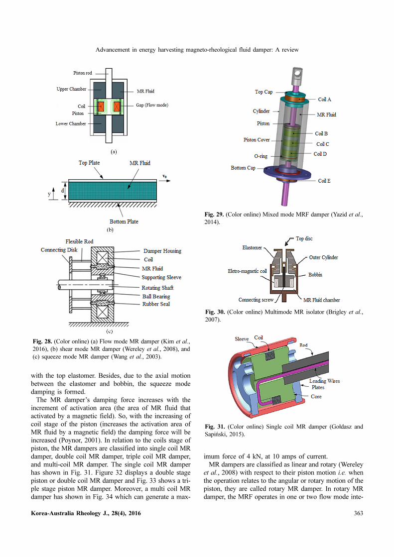
Advancement in energy harvesting magneto-rheological fluid damper: A review
Korea-Australia Rheology J., 28(4), 2016 363
with the top elastomer. Besides, due to the axial motion
between the elastomer and bobbin, the squeeze mode
damping is formed.
The MR damper’s damping force increases with the
increment of activation area (the area of MR fluid that
activated by a magnetic field). So, with the increasing of
coil stage of the piston (increases the activation area of
MR fluid by a magnetic field) the damping force will be
increased (Poynor, 2001). In relation to the coils stage of
piston, the MR dampers are classified into single coil MR
damper, double coil MR damper, triple coil MR damper,
and multi-coil MR damper. The single coil MR damper
has shown in Fig. 31. Figure 32 displays a double stage
piston or double coil MR damper and Fig. 33 shows a tri-
ple stage piston MR damper. Moreover, a multi coil MR
damper has shown in Fig. 34 which can generate a max-
imum force of 4 kN, at 10 amps of current.
MR dampers are classified as linear and rotary (Wereley
et al., 2008) with respect to their piston motion i.e. when
the operation relates to the angular or rotary motion of the
piston, they are called rotary MR damper. In rotary MR
damper, the MRF operates in one or two flow mode inte-
Fig. 28. (Color online) (a) Flow mode MR damper (Kim et al.,2016), (b) shear mode MR damper (Wereley et al., 2008), and(c) squeeze mode MR damper (Wang et al., 2003).
Fig. 29. (Color online) Mixed mode MRF damper (Yazid et al.,2014).
Fig. 30. (Color online) Multimode MR isolator (Brigley et al.,2007).
Fig. 31. (Color online) Single coil MR damper (Gołdasz andSapiński, 2015).

Raju Ahamed, Md Meftahul Ferdaus and Yancheng Li
364 Korea-Australia Rheology J., 28(4), 2016
grally. With regards to design and configuration, there
exist two styles of rotary MR damper and they are known
as continuous angle and limited angle revolution MR
damper (Imaduddin et al., 2013).
According to the valve location, MR dampers are sep-
arated into two categories, such as internal valve MRF
damper and external valve or bypass valve MRF damper.
In the internal valve MRF damper device, the valve usu-
ally attached to a piston inside the MRF damper and it
regulates MR fluid’s flow rate across the piston. On the
other hand, MRF damper with bypass valve has a per-
fectly sealed piston and the bypass channel outside the
damper is used for MR fluid flow. Simplicity in assembly,
easy maintenance, and reduction of induced temperature
from the coil to the MR fluid are some major advantages
of bypass valve based MR damper (Zhu et al., 2012). More-
over, it can apply for a different purpose without modify-
ing the damper structure. Figure 35 shows MR damper
with bypass valve. Moreover, Fig. 36 displays a bypass
rotary MR damper.
Besides these all classification MR damper can more
divided into some other types such as syringe-type MR
damper, sponge-type MR fluid damper, and MR squeeze-
film damper. A syringe-type MR damper has shown in
Fig. 37. This syringe type MR damper consists of MR
fluid into the straight flow channel, an electromagnetic
coil which is coiled outside straight flow channel, and a
piston and piston rod is situated at the terminal of each
side of the flow channel (Tong and Huang, 2014). This
change not only increases the length of the flow channel,
Fig. 32. (Color online) Double coil MR damper (Hu et al.,2016a).
Fig. 33. (Color online) Triple coil MR damper (Wilson et al.,2013).
Fig. 34. (Color online) Multi-coil MR damper (Gavin et al.,2001).
Fig. 35. (Color online) (a) MR damper with external bypass(Guo et al., 2015) and (b) MR damper with inner bypass (Bai et
al., 2015).

Advancement in energy harvesting magneto-rheological fluid damper: A review
Korea-Australia Rheology J., 28(4), 2016 365
but also changes the excitating paramagnetic particles
direction to be vertical with the direction of flow and thus
increases the ultimate shear strength of MRF. Moreover,
they are capable of generating a concentrated damping
force of 153N without applying a magnetic field (Tong and
Huang, 2014). Furthermore, in sponge type MR damper as
presented in Fig. 38, the MR fluid holds a spongy matrix
and it operates in shear mode with less difficulty and seal
problems. This types of MR damper have two forms
(expulsion and extraction) and usually used in a number of
applications especially in mechanical engineering such as
washing machines.
5. Models Classifications for MR Dampers
According to the method of modeling, MR damper’s
models might be classified as parametric dynamic models
or non-parametric dynamic models and can be further cat-
egorized as quasistatic models or dynamic models with
regards to their properties. Moreover, considering the revers-
ibility the models may possibly be seperated as dynamic
and inverse dynamic models. Various methods have been
suggested for finding MR damper models, recognizing
their parameters and generating self-powered MR damper
models. A few techniques have been suggested throughout
the years for getting MR damper models and distinguish-
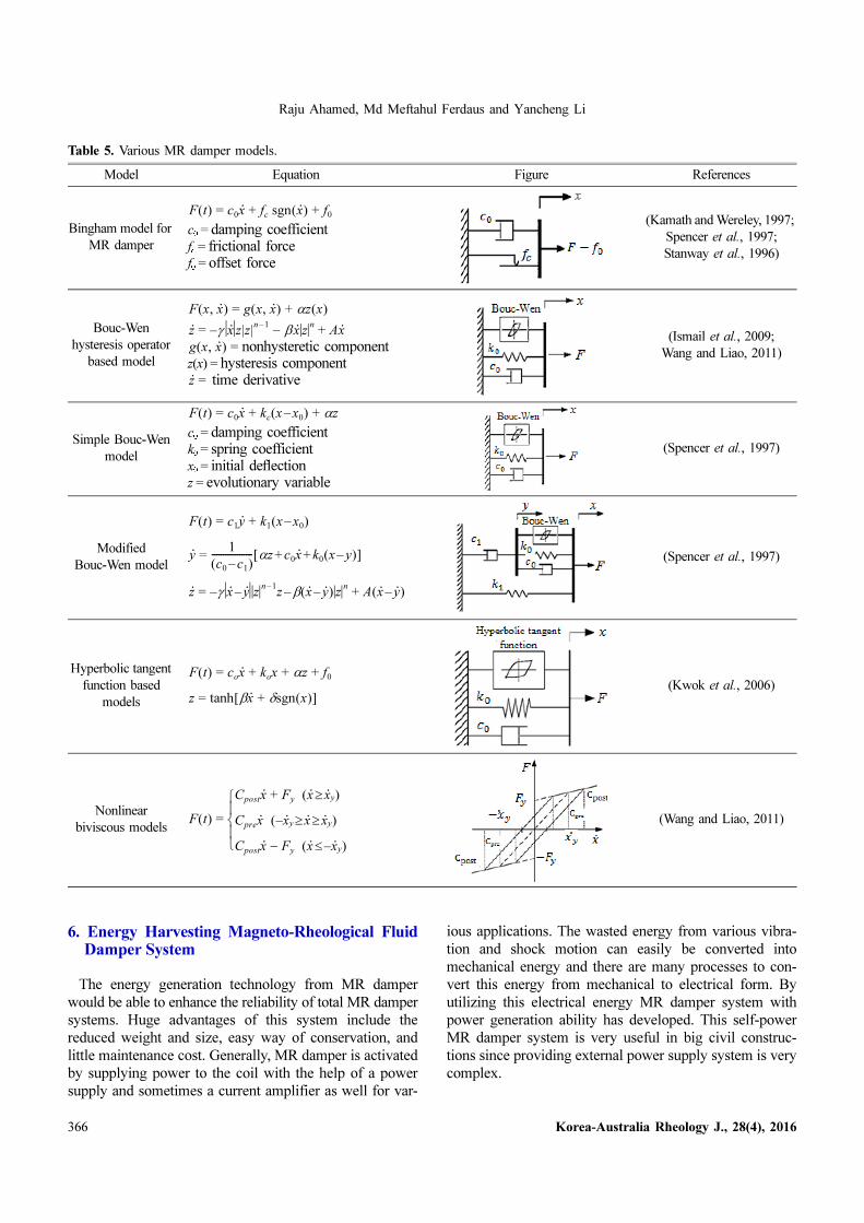
ing their parameters. Taking into account the Bingham
plastic model for MR fluid, Bingham model for MR
damper has been proposed (Stanway et al., 1996). This
model has a Coulomb friction element which is positioned
in parallel with regards to a viscous damper, as shown in
Table 5. Beyond the yield point, this model is used for
measured MR fluid behavior. In any case, the fluid’s rig-
idness is expected in the pre-yield area. Therefore, in
deformations and low shear rates, this model is not capa-
ble of defining the elastic properties of the fluid, that are
required for dynamic applications (Kamath and Wereley,
1997).
Moreover, to model hysteretic system Bouc-Wen model
is widely used because this model can mathematically
control. Moreover, Bouc-Wen model is particularly useful
and can display a comprehensive range of hysteretic
behavior. In 1976 Wen modified the hysteresis model of
Bouc which has an attractive mathematical ease. More-
over, it has the capability to characterize the huge type of
hysteretic behavior (Ismail et al., 2009). To simulate the
hysteresis loops, the Bouc-Wen model can use broadly
because it keeps the force versus displacement and force
versus velocity characteristics of the MR dampers (Wang
and Liao, 2011). Nevertheless, Bouc-Wen model’s non-
linear force and velocity response do not roll-off like
Bingham model in the yield region. In addition, by 1997
Spencer et al. suggested a revised form of the simple
Bouc-Wen model to better guess the MR damper response
for a variety of inputs. This modified phenomenological
MR damper model has shown in Table 5, which increases
the accuracy. The major limitations of this model ascend
from potential impreciseness because of the expected lin-
ear existing property and identification problem of a huge
number of parameters.
On the other hand, in 2006 an MR damper model based
on hyperbolic tangent function was proposed by Kwok et
al., as shown in Table 5. The idea was to use a hyperbolic
tangent function to signify the hysteresis, and linear func-
tion to show the stiffness and viscosity. Wang and Liao
(2011) referred to this model as “computationally effi-
cient” from the perspective of parameter identification as
well as following the addition of controller design and
application. Furthermore, Stanway et al. (1996) developed
the nonlinear biviscous model and assumed the MR fluids
behavior as plastic for not only in the pre-yield region but
also in the post-yield region. However, as the acknowl-
edged damping rates have a relationship only with a spe-
cific excitation, the response does not effectively work in
the situations where the excitation varies.
Fig. 36. (Color online) Bypass rotary MR damper (Imaduddin et
al., 2014).
Fig. 37. (Color online) (a) 3D drawing of syringe-type MRFdamper and (b) syringe-type MR damper (Tong and Huang, 2014).
Fig. 38. (Color online) MR sponge damper (Carlson, 2002).
Raju Ahamed, Md Meftahul Ferdaus and Yancheng Li
366 Korea-Australia Rheology J., 28(4), 2016
6. Energy Harvesting Magneto-Rheological FluidDamper System
The energy generation technology from MR damper
would be able to enhance the reliability of total MR damper
systems. Huge advantages of this system include the
reduced weight and size, easy way of conservation, and
little maintenance cost. Generally, MR damper is activated
by supplying power to the coil with the help of a power
supply and sometimes a current amplifier as well for var-
ious applications. The wasted energy from various vibra-
tion and shock motion can easily be converted into
mechanical energy and there are many processes to con-
vert this energy from mechanical to electrical form. By
utilizing this electrical energy MR damper system with
power generation ability has developed. This self-power
MR damper system is very useful in big civil construc-
tions since providing external power supply system is very
complex.
Table 5. Various MR damper models.
Model Equation Figure References
Bingham model for MR damper
c0 = damping coefficientfc = frictional forcef0 = offset force
(Kamath and Wereley, 1997; Spencer et al., 1997; Stanway et al., 1996)
Bouc-Wen hysteresis operator
based modelnonhysteretic component
z(x) = hysteresis componenttime derivative
(Ismail et al., 2009; Wang and Liao, 2011)
Simple Bouc-Wen model
c0 = damping coefficientk0 = spring coefficientx0 = initial deflectionz = evolutionary variable
(Spencer et al., 1997)
Modified Bouc-Wen model
(Spencer et al., 1997)
Hyperbolic tangent function based
models(Kwok et al., 2006)
Nonlinear biviscous models
(Wang and Liao, 2011)
F t( ) = c0x· + fc sgn x·( ) + f0
F x, x·( ) = g x, x·( ) + αz x( )
z· = γ– x· z|z|n 1– − βx· zn + Ax·
g x, x·( ) =
z· =
F t( ) = c0x· + kc x x0–( ) + αz
F t( ) = c1y· + k1 x x0–( )
y· = 1
c0 c1–( )------------------ αz c0x
· k0 x y–( )+ +[ ]
z· = γ– x· y·– zn 1–
z β– x· y·–( ) zn + A x· y·–( )
F t( ) = cox· + kox + αz + f0
z = tanh βx· + δsgn x( )[ ]
F t( ) =
Cpostx· + Fy x· x·y≥( )
Cprex· x·y– x· x·y≥ ≥( )
Cpostx· − Fy x· x·y–≤( )⎩
⎪⎨⎪⎧

Advancement in energy harvesting magneto-rheological fluid damper: A review
Korea-Australia Rheology J., 28(4), 2016 367
6.1. Energy harvesting by permanent magnet and coilarrangement
An electromagnetic induction (EMI) device is attached
to the MR damper to generate energy which is introduced
by Cho et al. (2005; 2007). The EMI device consists of a
permanent magnet and a coil. This EMI device can gen-
erate electrical energy from mechanical vibration energy
and generated energy can supply into MR damper’s coil.
The schematic structure of their proposed MR damper is
exposed in Fig. 39 and model is expressed by the Eqs. (1)
and (2).
, (1)
. (2)
Moreover, Jung et al. designed a large scale EMI system
based smart MR damper to generate energy and evaluated
its performances experimentally (Jung et al., 2008; Kim et
al., 2010). The EMI system has permanent magnet and
coil arrangement displayed in Figs. 40 and 41, which can
generate energy from reciprocal motions. According to the
Faraday’s law, the generated voltage from the EMI system
is linearly proportional to the relative velocity across the
MRF damper. The experimental results show that this
EMI system can provide a sensing capability that is useful
in the MRF damper-based control systems and the EMI
can work as an input power source for damper (Kim et al.,2010).
Chen and Liao (2012a) designed an energy generation
system in MR damper which consists multi-pole (each
pole pair has one permanent magnet, coil, and pole piece)
power generator. In addition, this proposed designed has
the self-sensing capability that combines energy genera-
tion and dynamic sensing damping technology into one
device, as displayed in Fig. 42. Figure 43 exhibits the pro-
totype of that MR damper.
The experiment result of this MR damper model has
shown that it has sufficient power production and velocity
sensing abilities relevant to different dynamic methods.
The size of this model is large so it is suitable for double-
f = c1y· + k1 x x0–( )
y· = 1
c0 c1+( )------------------ αz k0 x y–( ) c0+ + x·[ ]
Fig. 39. (Color online) Schematic of a smart passive MRdamper system (Cho et al., 2005).
Fig. 40. (Color online) (a) Schematic of EMI system with MRdamper and (b) large scale EMI system (Jung et al., 2008).
Fig. 41. (Color online) Proposed EMI system based MR damper: (a) Prototype, (b) schematic configuration, and (c) 3D section view(Kim et al., 2010).

Raju Ahamed, Md Meftahul Ferdaus and Yancheng Li
368 Korea-Australia Rheology J., 28(4), 2016
ended MR damper construction and applicable in civil
structures.
Three years later, Chen et al. (2015) again proposed
another energy generated MR damper which is known as
a regenerative magnetorheological damper. Compared to
the previous model, this proposed design has additional
spring. The proposed model has shown in Fig. 44.
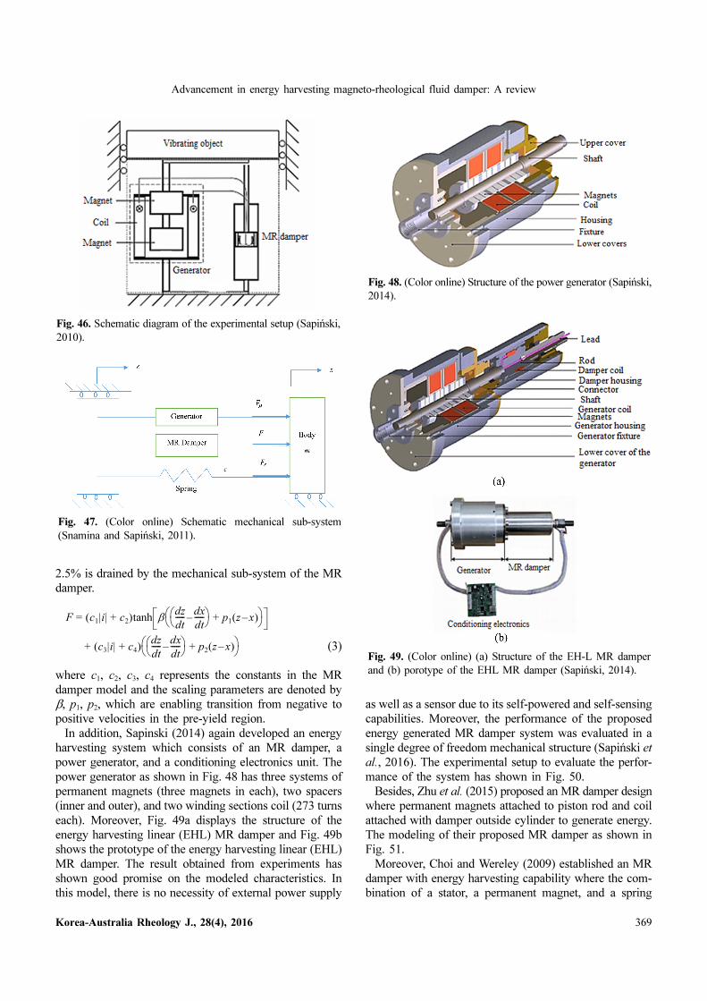
Sapiński (2010) developed and experimentally tested a
power generator for linear MR damper. The generator has
permanent magnets and coils with foil winding. Figure 48
displays the structure of the power generator and Fig. 45
shows the prototype of the power generator. The device
produces electrical energy which is delivered to the MR
damper in order to verify the damping characteristic. The
device can change the MR damper’s reciprocal motion into
kinetic energy which has seen from experimental results.
That is the reason the generator might be utilized to
develop vibration control system utilizing MR damper
without the requirement of any external power. The exper-
imental setup with MR damper is exposed in Fig. 46.
Later, they again developed the power generator known as
electromagnetic power generator by changing permanent
magnet (incorporating high-performance bulk magnets)
and proposed an energy generation system (Snamina and
Sapiński, 2011).
Moreover, this system has a mechanical and electrical
sub-system along with MR damper displayed in Fig. 47.
The damping force generated by this model is expressed
in the following Eq. (3). The generator is working as an
energy source and the necessary energy is generated uti-
lizing the vibrations. From this generated energy around
Fig. 42. (Color online) Sectional view of a self-sensing and self-powered MR damper (Chen and Liao, 2012a; 2012b).
Fig. 43. (Color online) Images of fabricated prototype: (a)Developed assembled prototype and (b) prototype’s disassem-bled parts (Chen and Liao, 2012a).
Fig. 44. (Color online) Cross-sectional view of the proposedregenerative MR damper (Chen et al., 2015).
Fig. 45. (Color online) Prototype of the power generator(Sapiński, 2010).
Advancement in energy harvesting magneto-rheological fluid damper: A review
Korea-Australia Rheology J., 28(4), 2016 369
2.5% is drained by the mechanical sub-system of the MR
damper.
(3)
where c1, c2, c3, c4 represents the constants in the MR
damper model and the scaling parameters are denoted by
β, p1, p2, which are enabling transition from negative to
positive velocities in the pre-yield region.
In addition, Sapinski (2014) again developed an energy
harvesting system which consists of an MR damper, a
power generator, and a conditioning electronics unit. The
power generator as shown in Fig. 48 has three systems of
permanent magnets (three magnets in each), two spacers
(inner and outer), and two winding sections coil (273 turns
each). Moreover, Fig. 49a displays the structure of the
energy harvesting linear (EHL) MR damper and Fig. 49b
shows the prototype of the energy harvesting linear (EHL)
MR damper. The result obtained from experiments has
shown good promise on the modeled characteristics. In
this model, there is no necessity of external power supply
as well as a sensor due to its self-powered and self-sensing
capabilities. Moreover, the performance of the proposed
energy generated MR damper system was evaluated in a
single degree of freedom mechanical structure (Sapiński et
al., 2016). The experimental setup to evaluate the perfor-
mance of the system has shown in Fig. 50.
Besides, Zhu et al. (2015) proposed an MR damper design
where permanent magnets attached to piston rod and coil
attached with damper outside cylinder to generate energy.
The modeling of their proposed MR damper as shown in
Fig. 51.
Moreover, Choi and Wereley (2009) established an MR
damper with energy harvesting capability where the com-
bination of a stator, a permanent magnet, and a spring
F = c1|i| + c2( )tanh βdz
dt----- dx
dt-----–⎝ ⎠
⎛ ⎞ + p1 z x–( )⎝ ⎠⎛ ⎞
+ c3|i| + c4( )dz
dt----- dx
dt-----–⎝ ⎠
⎛ ⎞ + p2 z x–( )⎝ ⎠⎛ ⎞
Fig. 46. Schematic diagram of the experimental setup (Sapiński,2010).
Fig. 47. (Color online) Schematic mechanical sub-system(Snamina and Sapiński, 2011).
Fig. 48. (Color online) Structure of the power generator (Sapiński,2014).
Fig. 49. (Color online) (a) Structure of the EH-L MR damperand (b) porotype of the EHL MR damper (Sapiński, 2014).

Raju Ahamed, Md Meftahul Ferdaus and Yancheng Li
370 Korea-Australia Rheology J., 28(4), 2016
functions as an energy-harvesting dynamic vibration absorber
(DVA), as shown in Fig. 52. In this damper model, two
permanent magnets are attached with spring in the top of
the piston head inside the MR damper and these magnets
are surrounded by coils which are attached to piston rod.
With the movement of piston rod, the magnet also moves
and generates energy inside the coil. The generated energy
is used directly supplied to the coils of MR damper and
avoids the usage of extra sensors.
Moreover, another novel MR damper model with energy
harvesting capability as shown in Fig. 53 was designed by
Hu et al. (2016b) based on electromagnetic introduction
(EMI) principle. In this new MR damper model, the power
generator has added inside the MR damper. Eight pairs of
permanent magnets are screwed with the shaft and two
types of the coil (coil A and coil B) arrangements are
attached inside the piston rod. The connected 0º and 180º
phase coils are known as coil A and connected 90º and
270º phase coils are known as coil B. When the piston
moves then coil arrangements also move along with piston
and these coils cut the magnetic field of the permanent
Fig. 50. Experimental setup of the proposed energy harvestedMR damper system (Sapiński et al., 2016).
Fig. 51. Structure of the MR damper with power generator (Zhuet al., 2015).
Fig. 52. (Color online) (a) Schematic diagram and (b) single-DOF engine mount system of self-powered MR damper (Choiand Wereley, 2009).
Fig. 53. (Color online) (a) Schematic diagram of the proposed MRdamper and (b) prototype of the MR damper (Hu et al., 2016b).

Advancement in energy harvesting magneto-rheological fluid damper: A review
Korea-Australia Rheology J., 28(4), 2016 371
magnet which is attached with a screw inside the damper.
When this interaction occurred between magnet and coil
then electricity produces inside the coil A and coil B. It
can generate about 1.0 V DC voltage at 0.06 ms−1 and can
produce almost 750 N damping force at the current 0.6 A.
6.2. Energy harvesting by Induction coilWang and Bai (2013) proposed an MR damper model to
generate energy by using induction coils only rather than
using magnet and coil arrangement. This model proposed
an integrated relative displacement sensor (IRDS) tech-
nology to convert MR dampers self-sensing with the help
of electromagnetic induction. This proposed model com-
prises of an exciting coil convoluted around the piston and
an induction coil curled on the nonmagnetic cylinder. The
piston coil acts as the exciting coils of the MR fluid and
wound coil of the cylinder acts as the induction coil of the
model, as shown in Fig. 54. The prototype of the proposed
model has shown in Fig. 55. This new method cuts the
application cost of the MR damper.
Moreover, another series of MR dampers with linear
variable differential sensor (LVDS) were developed by Hu
et al. (2015a; 2015b) which has self-sensing ability. Both
proposed models are shown in Figs. 56 and 57 contains an
exciting coil wounded around the piston and a differential
induction coil wound on the nonmagnetic cylinder. When
the input current applied inside the piston head coil, then
it provides magnetic fields to both the linear variable dif-
ferential sensor (LVDS) and MR fluids and some electro-
motive forces and the output voltage generated inside the
differential induction coil. However, this model has appli-
cation in the field of vehicle manufacture, bridge building,
and so on. Schematic diagram of the projected MR damper’s
electronic system has shown in Fig. 58.
6.3. Energy harvesting by rack and pinion mechanismWang et al. (2009) presented MR damper with a sensing
semi-active control system and energy harvesting ability.
This system has a rack and pinion mechanism along with
a linear permanent magnet used as DC generator, MR
damper with current control capacity through a control
circuit. An ideal active control system is designed using a
Fig. 54. (Color online) (a) Designed self-powered MR damperbased on electromagnetic induction and (b) schematic of the pro-posed electronic system (Wang and Bai, 2013).
Fig. 55. (Color online) Prototype of the developed MR damper(a) before assembly and (b) after assembly (Wang and Bai, 2013).
Fig. 56. (Color online) (a) Schematic of the DDSMRD and (b)prototype of the DDSMRD (Hu et al., 2015a).

Raju Ahamed, Md Meftahul Ferdaus and Yancheng Li
372 Korea-Australia Rheology J., 28(4), 2016
linear quadratic regulator (LQR), where the LQR-depen-
dent clipped optimal control along with skyhook control is
utilized to regulate an MRF damper. Figure 59 shows the
flowchart of their proposed model. The model is expressed
by Eq. (4).
. (4)
The model has proved that, have similar control perfor-
mance is observed in five different strategies such as one
perfect active control, two semi-active controls, and two
self-powered semi-active controls with respect to peer
response and bearing response as well. The response is
monitored by using only one accelerometer.
6.4. Energy harvesting by ball and screw mechanismDong (2015) proposed an axial flux permanent magnet
energy harvester (AFPMEH) and examined it for a vehicle
suspension system. The linear motion of the MR damper
has changed to rotary motion of AFPMEH by back drive
ball and screw mechanism. The proposed energy harvester
as shown in Fig. 60a consists of two identical rotor (core-
less) discs and a single stator. For this research there are
six (four-layer) windings and eight poles are elected. Every
rotor has eight number of permanent magnets (NdFeB)
and these magnets are supported by iron disc. Moreover,
the proposed MR damper can work with hybrid mode
y· = 1
c0 c1+( )------------------ αz k0 x y–( ) c0+ + x·[ ]
Fig. 57. (Color online) Prototype model of the proposed MRdamper (a) different parts of the prototype and (b) after assem-bly (Hu et al., 2015b).
Fig. 58. (Color online) Schematic diagram of the proposed MRdamper’s electronic system (Hu et al., 2015b).
Fig. 59. (Color online) The flowchart of the control system withenergy regeneration (Wang et al., 2009).
Fig. 60. (Color online) (a) Picture of the AFPMEH and (b)schematic diagram of the proposed MR damper (Dong, 2015).

Advancement in energy harvesting magneto-rheological fluid damper: A review
Korea-Australia Rheology J., 28(4), 2016 373
(valve and shear mode together) as shown in Fig. 60b. The
full experimental setup has shown in Fig. 61. Further, in
B grade road this energy harvester can generate about 2 W
when velocity is around 0.1668 ms−1 but in D grade road
the generated energy is about 45W when velocity is around
0.6693 ms−1 (Dong, 2015).
6.5. Energy harvesting by using generator and motorChu et al. (2016) designed an energy harvested MR
damper which has controllable damping along with energy
generation mechanism into one device. Their MR damper’s
energy harvesting part has a unique mechanism of trans-
forming the linear motion into rotary motion, which has
better stability and cost-effectiveness in comparison with
other mechanical transmissions. A sectional view of the
regenerative MR damper has exhibited in Fig. 62. A Maxon
motor (as shown in Fig. 64) works as a power generator
and effectively converts energy from mechanical to elec-
trical, which is sufficient enough for supplying power to
MR damper. It has several advantages over conventional
approaches, like as it is an integrated device, compara-
tively light weight, easy to install and less maintenance is
needed. Figure 63 shows their proposed MR damper with
damping and power generation parts. Moreover, it has
application in the field of vehicles, smart prostheses, in
various civil constructions like bridges and buildings.
On the other hand, Xinchun et al. (2015) proposed a
novel magnetorheological (MR) damper which has energy
harvesting capability. The system has ball-screw mecha-
nisms for harvesting energy from vibration. Moreover,
external vibration energy is converted into electricity energy
with the help of a rotary permanent magnet DC generator.
The developed self-powered MR has shown in Figs. 65
and 66 shows the prototype of the projected MRD. Fur-
thermore, from experiment, it is observed that the MR
damper’s damping force is possible to use with good self-
flexibility for both direct supply and rectified supply mode.
This damper can save energy with less maintenance cost.
Wang et al. (2012) investigated a new energy harvesting
device which has impeller and generator combinations to
generate energy from fluid damper. The MR fluid was
used as an example of fluid damper in this investigation
and the energy generation system from MR damper has
shown in Fig. 67. Moreover, Yu et al. (2014) proposed a
new MR damper based on energy-harvesting device sys-
tem. Actually, both two research the energy harvesting sys-
tems were proposed for the wireless sensor system. The
whole system has an energy-harvesting device, an energy-
management circuit, wireless sensor node, and MR damper.
The energy-harvesting device as shown in Fig. 68 consists
of an electromagnetic energy converter, an impeller, and a
sealing unit where electromagnetic energy converter and
impeller are coaxially connected.
Fig. 61. (Color online) (a) Schematic of the MR damper andAFPMEH setup and (b) experimental setup (Dong, 2015).
Fig. 62. (Color online) Sectional view of the energy harvestingMR damper (Chu et al., 2016).
Fig. 63. (Color online) Images of energy harvesting MR damper.(a) Prototype and (b) disassembled parts of MR damper andpower generator (Chu et al., 2016).
Fig. 64. (Color online) Image of motion rectifier prototypemounted with ZGA 25RP motor (Chu et al., 2016).

Raju Ahamed, Md Meftahul Ferdaus and Yancheng Li
374 Korea-Australia Rheology J., 28(4), 2016
With the movement of piston head inside the damper,
the MR fluid also moves and it changes the velocity direc-
tion. Furthermore, with the changing of the movement of
the MR fluid flow the impeller induces torque and rotates.
The electromagnetic energy converter performs with the
impeller running and generates electric energy.
Therefore, this device can generate the electrical energy
used by wireless sensor node with the assistance of an
energy management circuit. Also, it has seen that the energy
harvester has no effect with regards to the increment of
applied current to the MR damper.
7. Conclusion
MR damper is a smart semi-active device, which has
some certain advantages over passive and active devices
like continuous controllability, comparatively light weight,
Fig. 65. (Color online) Two different assemblies of the double-ended MRD. (a) The conventional MRD and (b) the self-pow-ered MRD (Xinchun et al., 2015).
Fig. 66. (Color online) Photographs of the proposed MRD. (a)MRD, (b) the generator, and (c) the ball screw (Xinchun et al.,2015).
Fig. 67. (Color online) Energy generation system from fluid damper (Wang et al., 2012).
Fig. 68. (Color online) (a) Schematic of the proposed MRdamper, (b) assembly parts, and (c) prototype of the proposeddamper (Yu et al., 2014).

Advancement in energy harvesting magneto-rheological fluid damper: A review
Korea-Australia Rheology J., 28(4), 2016 375
and low power consumption. MR dampers basic design
and construction along with their various types configu-
ration are discussed in the paper to understand their ver-
satile applicability in a wide area as mentioned in the
literature. The way of characterizing the non-linear com-
plex behavior of MR damper is accomplished with the
support of some famous MR damper mathematical mod-
elings and all these are summarized here. To cope up with
altered applications, design modification, optimization,
and advancement are specified in this review. Self-energy
generation is crying need of present era and challenge of
contemporary technology. In this regard, self- powered i.e.
energy harvesting capability of MR damper from the wasted
mechanical energy are conferred here with their proper
modeling. Overall, various MR dampers’ design, fabrica-
tion and nifty application, damper’s design optimization,
advancement, and latest self-powered technology are
appraised in this paper.
Acknowledgement
The authors would like to thank the Faculty of Engineering,
International Islamic University Malaysia for giving the
chance of using the basic structural laboratory.
References
Ahamed, R., M.M. Rashid, M.M. Ferdaus, and H.M. Yusof,2016, Design and modeling of energy generated magneto rhe-ological damper, Korea-Aust. Rheol. J. 28, 67-74.
Ahmadian, M. and J.C. Poynor, 2001, An evaluation of magnetorheological dampers for controlling gun recoil dynamics,Shock Vib. 8, 147-155.
Ahmadian, M., R. Appleton, and J.A. Norris, 1999, Design anddevelopment of magneto-rheological dampers for bicycle sus-pensions, ASME-Publications-DSC 67, 737-741.
Bai, X.X., N.M. Wereley, and W. Hu, 2015, Maximizing semi-active vibration isolation utilizing a magnetorheological damperwith an inner bypass configuration, J. Appl. Phys. 117, 17C711.
Benetti, M. and E. Dragoni, 2006, Nonlinear magnetic analysis ofmulti-plate magnetorheological brakes and clutches, COMSOL
Users Conference, Milano, Italy.Brigley, M., Y.T. Choi, N.M. Wereley, and S.B. Choi, 2007,
Magnetorheological isolators using multiple fluid modes, J.
Intell. Mater. Syst. Struct. 18, 1143-1148.Carlson, J.D., 2002, Controlling vibration with magnetorheolog-
ical fluid damping, Sensors 19, 30-35.Carlson, J.D. and M.J. Chrzan, 1994, Magnetorheological fluid
dampers, US Patent US5277281 A.Carlson, J.D. and M.R. Jolly, 2000, MR fluid, foam and elasto-
mer devices, Mechatronics 10, 555-569.Case, D., B. Taheri, and E. Richer, 2011, Dynamic magnetorhe-
ological damper for orthotic tremor suppression, 2011 Mathe-
matics and Engineering Conference (HUIC 2011), Honolulu,USA.
Case, D., B. Taheri, and E. Richer, 2013, Design and character-ization of a small-scale magnetorheological damper for tremorsuppression, IEEE-ASME Trans. Mechatron. 18, 96-103.
Chen, C., L. Zou, and W.H. Liao, 2015, Regenerative magneto-rheological dampers for vehicle suspensions, Proc. SPIE 9435,94353K.
Chen, C. and W.H. Liao, 2012a, A self-sensing magnetorheolog-ical damper with power generation, Smart Mater. Struct. 21,025014.
Chen, C. and W.H. Liao, 2012b, Feasibility study of self-poweredmagnetorheological damper systems, Proc. SPIE 8341, 83410Q.
Chen, J.Z. and W.H. Liao, 2010, Design, testing and control of amagnetorheological actuator for assistive knee braces, Smart
Mater. Struct. 19, 035029.Cho, S.W., H.J. Jung, and I.W. Lee, 2005, Smart passive system
based on magnetorheological damper, Smart Mater. Struct. 14,707-714.
Choi, K.M., H.J. Jung, H.J. Lee, and S.W. Cho, 2007, Feasibilitystudy of an MR damper-based smart passive control systememploying an electromagnetic induction device, Smart Mater.
Struct. 16, 2323-2329.Choi, S.B., S.K. Lee, and Y.P. Park, 2001, A hysteresis model for
the field-dependent damping force of a magnetorheologicaldamper, J. Sound Vibr. 245, 375-383.
Choi, S.B., W. Li, M. Yu, H. Du, J. Fu, and P.X. Do, 2016, Stateof the art of control schemes for smart systems featuring mag-neto-rheological materials, Smart Mater. Struct. 25, 043001.
Choi, Y.T. and N.M. Wereley, 2009, Self-powered magnetorhe-ological dampers, J. Vib. Acoust. 131, 044501.
Choi, Y.T., J.U. Cho, S.B. Choi, and N.M. Wereley, 2005, Con-stitutive models of electrorheological and magnetorheologicalfluids using viscometers, Smart Mater. Struct. 14, 1025-1036.
Chooi, W.W. and S.O. Oyadiji, 2008, Design, modelling, andtesting of magnetorheological (MR) dampers using analyticalflow solutions, Comput. Struct. 86, 473-482.
Chrzan, M.J. and J.D. Carlson, 2001, MR fluid sponge devicesand their use in vibration control of washing machines, Proc.
SPIE 4331, 370-378.Chu, K.S., L. Zou, and W.H. Liao, 2016, A mechanical energy
harvested magnetorheological damper with linear-rotary motionconverter, Proc. SPIE 9803, 980309.
Dong, X., 2015, Design and characterization of axial flux per-manent magnet energy harvester for vehicle magnetorheolog-ical damper, Smart Mater. Struct. 25, 015024.
Du, H., K.Y. Sze, and J. Lam, 2005, Semi-active H∞ control ofvehicle suspension with magneto-rheological dampers, J.
Sound Vibr. 283, 981-996.Dutta, S. and S.B. Choi, 2016, Control of a shimmy vibration in
vehicle steering system using a magneto-rheological damper, J.
Vib. Control, 1077546316652786.Dutta, S., S.M. Choi, and S.B. Choi, 2016, A new adaptive slid-
ing mode control for Macpherson strut suspension system withmagneto-rheological damper, J. Intell. Mater. Syst. Struct.,1045389X16641221.
Ehrgott, R. and S.F. Masri, 1992, Modeling the oscillatorydynamic behaviour of electrorheological materials in shear,Smart Mater. Struct. 1, 275-285.

Raju Ahamed, Md Meftahul Ferdaus and Yancheng Li
376 Korea-Australia Rheology J., 28(4), 2016
Ferdaus, M.M., M.M. Rashid, M.M.I. Bhuiyan, A.G.B.A. Muth-alif, and M.R. Hasan, 2013, Novel design of a self poweredand self sensing magneto-rheological damper, IOP Conf. Ser.-
Mater. Sci. Eng. 53, 012048.Fodor, M.G. and R. Redfield, 1993, The variable linear transmis-
sion for regenerative damping in vehicle suspension control,Veh. Syst. Dyn. 22, 1-20.
Gavin, H., J. Hoagg, and M. Dobossy, 2001, Optimal design ofMR dampers, US-Japan Workshop on Smart Structures for
Improved Seismic Performance in Urban Regions, Seattle,USA, 225-236.
Gołdasz, J. and B. Sapiński, 2015, Configurations of MR damp-ers In: Gołdasz, J. and B. Sapiński, eds., Insight into Magne-
torheological Shock Absorbers, Springer, 25-49.Goncalves, F. and J. Carlson, 2009, An alternate operation mode
for MR fluids-magnetic gradient pinch, J. Phys.-Conf. Ser. 149,012050.
Goncalves, F.D., J.H. Koo, and M. Ahmadian, 2006, A review ofthe state of the art in magnetorheological fluid technologies -Part I: MR fluid and MR fluid models, Shock Vib. Digest 38,203-219.
Grunwald, A. and A.G. Olabi, 2008, Design of magneto-rheo-logical (MR) valve, Sens. Actuator A-Phys. 148, 211-223.
Guglielmino, E., T. Sireteanu, C.W. Stammers, G. Ghita, and M.Giuclea, 2008, Semi-active Suspension Control: Improved Vehi-
cle Ride and Road Frienliness, Springer, London.Guo, C., X. Gong, L. Zong, C. Peng, and S. Xuan, 2015, Twin-
tube- and bypass-containing magneto-rheological damper foruse in railway vehicles, Proc. Inst. Mech. Eng. Part F-J Rail
Rapid Transit 229, 48-57.Guo, N., H. Du, and W. Li, 2003, Finite element analysis and
simulation evaluation of a magnetorheological valve, Int. J.
Adv. Manuf. Technol. 21, 438-445.Ha, S.H., M.S. Seong, and S.B. Choi, 2013, Design and vibration
control of military vehicle suspension system using magneto-rheological damper and disc spring, Smart Mater. Struct. 22,065006.
Ha, S.H., S.B. Choi, and W.H. You, 2008, Vibration control andsteering performance evaluation of railway vehicle using mag-netorheological damper, Trans. Korean Soc. Noise Vib. Eng.
18, 524-532.Herr, H., D. Paluska, and P. Dilworth, 2006, Artificial human
limbs and joints employing actuators, springs, and variable-damper elements, US Patent US20060249315 A1.
Hitchcock, G.H., F. Gordaninejad, and X. Wang, 2002, New by-pass, fail-safe, magnetorheological fluid damper, Proc. SPIE
4696, 345-351.Hong, H., S. Tang, Y. Sheng, and W. Cui, 2015, Magnetic circuit
design and computation of a magnetorheological damper withexterior coil, 2015 IEEE International Conference on Mecha-
tronics and Automation (ICMA 2015), Beijing, China, 60-64.Hong, S.R., S. John, N.M Wereley, Y.T. Choi, and S.B. Choi,
2008, A unifying perspective on the quasi-steady analysis ofmagnetorheological dampers, J. Intell. Mater. Syst. Struct. 19,959-976.
Hsu, P., 1996, Power recovery property of electrical active sus-pension systems, 31st Intersociety Energy Conversion Engineer-
ing Conference (IECEC 96), Washington, USA, 1899-1904.Hu, G., F. Liu, Z. Xie, and M. Xu, 2016a, Design, analysis, and
experimental evaluation of a double coil magnetorheologicalfluid damper, Shock Vib. 2016, 4184726.
Hu, G., W. Zhou, and W. Li, 2015a, A new magnetorheologicaldamper with improved displacement differential self-inducedability, Smart Mater. Struct. 24, 087001.
Hu, G., W. Zhou, M. Liao, and W. Li, 2015b, Static and dynamicexperiment evaluations of a displacement differential self-induced magnetorheological damper, Shock Vib. 2015, 295294.
Hu, G., Y. Lu, S. Sun, and W. Li, 2016b, Performance analysis ofa magnetorheological damper with energy harvesting ability,Shock Vib. 2016, 2959763.
Ichwan, B., S.A. Mazlan, F. Imaduddin, Ubaidillah, T. Koga, andM.H. Idris, 2016, Development of a modular MR valve usingmeandering flow path structure, Smart Mater. Struct. 25, 037001.
Imaduddin, F., S.A. Mazlan, and H. Zamzuri, 2013, A design andmodelling review of rotary magnetorheological damper, Mater.
Des. 51, 575-591.Imaduddin, F., S.A. Mazlan, H. Zamzuri, and M.A. Abdul Rah-
man, 2014, Bypass rotary magnetorheological damper for auto-motive applications, Appl. Mech. Mater. 663, 685-689.
Ismail, M., F. Ikhouane, and J. Rodellar, 2009, The hysteresisBouc-Wen model, a survey, Arch. Comput. Method Eng. 16,161-188.
Jin, G., M.K. Sain, and B.E. Spencer, 2005, Nonlinear blackboxmodeling of MR-dampers for civil structural control, IEEE
Trans. Control Syst. Technol. 13, 345-355.Jolly, M.R., 2001, Pneumatic motion control using magnetorhe-
ological technology, Proc. SPIE 4332, 300-307.Jolly, M.R., J.W. Bender, and J.D. Carlson, 1998, Properties and
applications of commercial magnetorheological fluids, Proc.
SPIE 3327, 262-275.Jung, H.J., B.F. Spencer, Y.Q. Ni, and I.W. Lee, 2004, State-of-
the-art of semiactive control systems using MR fluid dampersin civil engineering applications, Struct. Eng. Mech. 17, 493-526.
Jung, H.J., D.D. Jang, and H.J. Lee, 2008, Self-powered smartdamping system using MR damper, 15th International Con-
gress on Sound and Vibration (ICSV15), Daejeon, Korea, 364-371.
Kaluvan, S., Y.D. Park, and S.B. Choi, 2016, A novel resonancebased magnetic field sensor using a magneto-rheological fluid,Sens. Actuator A-Phys. 238, 19-24.
Kamath, G., N. Wereley, and M. Jolly, 1997, Analysis and testingof a model-scale magnetorheological fluid helicopter lag modedamper, American Helicopter Society 53rd Annual Forum, Vir-ginia Beach, USA, 1325-1335.
Kamath, G.M. and N.M. Wereley, 1997, A nonlinear viscoelastic-plastic model for electrorheological fluids, Smart Mater. Struct.
6, 351-359.Karakoc, K., E.J. Park, and A. Suleman, 2008, Design consid-
erations for an automotive magnetorheological brake, Mecha-
tronics 18, 434-447.Kato, H. and O.M. Phillips, 1969, On the penetration of a tur-
bulent layer into stratified fluid, J. Fluid Mech. 37, 643-655.Kciuk, M. and R. Turczyn, 2006, Properties and application of

Advancement in energy harvesting magneto-rheological fluid damper: A review
Korea-Australia Rheology J., 28(4), 2016 377
magnetorheological fluids, J. Achiev. Mater. Manuf. Eng. 18,127-130.
Kim, I.H., H.J. Jung, and J.H. Koo, 2010, Experimental evalua-tion of a self-powered smart damping system in reducingvibrations of a full-scale stay cable, Smart Mater. Struct. 19,115027.
Kim, J.H. and J.H. Oh, 2001, Development of an above kneeprosthesis using MR damper and leg simulator, IEEE Interna-
tional Conference on Robotics and Automation (2001 ICRA),Seoul, Korea, 3686-3691.
Kim, K., Z. Chen, D. Yu, and C. Rim, 2016, Design and exper-iments of a novel magneto-rheological damper featuring bifoldflow mode, Smart Mater. Struct. 25, 075004.
Kim, K.J., C.W. Lee, and J.H. Koo, 2008, Design and modelingof semi-active squeeze film dampers using magneto-rheologi-cal fluids, Smart Mater. Struct. 17, 035006.
Klingenberg, D.J., 2001, Magnetorheology: Applications andchallenges, AIChE J. 47, 246-249.
Koo, J.H., F.D. Goncalves, and M. Ahmadian, 2006, A compre-hensive analysis of the response time of MR dampers, Smart
Mater. Struct. 15, 351-358.Kordonsky, W.I., 1993a, Elements and devices based on magne-
torheological effect, J. Intell. Mater. Syst. Struct. 4, 65-69.Kordonsky, W.I., 1993b, Magnetorheological effect as a base of
new devices and technologies, J. Magn. Magn. Mater. 122,395-398.
Kordonski, W.I. and S.R. Gorodkin, 1996, Magnetorheologicalfluid-based seal, J. Intell. Mater. Syst. Struct. 7, 569-572.
Kordonsky, W.I., S.R. Gorodkin, A.V. Kolomentsev, V.A. Kuzmin,A.V. Luk'ianovich, N.A. Protasevich,, I.V. Prokhorov, and Z.P.Shulman, 1995, Magnetorheological valve and devices incor-porating magnetorheological elements, US Patent US5452745A.
Kwok, N.M., Q.P. Ha, T.H. Nguyen, J. Li, and B. Samali, 2006,A novel hysteretic model for magnetorheological fluid damp-ers and parameter identification using particle swarm optimi-zation, Sens. Actuator A-Phys. 132, 441-451.
Lara-Prieto, V., R. Parkin, M. Jackson, V. Silberschmidt, and K.Zbigniew, 2009, Vibration characteristics of MR cantileversandwich beams: Experimental study, Smart Mater. Struct. 19,015005.
Lau, Y.K. and W.H. Liao, 2005, Design and analysis of magne-torheological dampers for train suspension, Proc. Inst. Mech.
Eng. Part F-J. Rail Rapid Transit 219, 261-276.Lee, H.G., K.G. Sung, S.B. Choi, K.W. Min, and S.H. Lee, 2006a,
Control responses of commercial magnetorheological damperfor passenger vehicles, 10th International Conference on Elec-
trorheological Fluids and Magnetorheological Suspensions,Lake Tahoe, USA, 681-688.
Lee, S.H., E.C. Park, K.J. Youn, K.W. Min, L. Chung, S.B. Choi,K.G. Sung, and H.G. Lee, 2006b, Response control of a real-scaled five-story structure using magneto-rheological damper,10th International Conference on Electrorheological Fluids and
Magnetorheological Suspensions, Lake Tahoe, USA, 689-695.Lee, U., D. Kim, N. Hur, and D. Jeon, 1999, Design analysis and
experimental evaluation of an MR fluid clutch, J. Intell. Mater.
Syst. Struct. 10, 701-707.
Lesieutre, G.A., G.K. Ottman, and H.F. Hofmann, 2004, Dampingas a result of piezoelectric energy harvesting, J. Sound Vibr.
269, 991-1001.Liao, W.H. and D.H. Wang, 2003, Semiactive vibration control of
train suspension systems via magnetorheological dampers, J.
Intell. Mater. Syst. Struct. 14, 161-172.Liu, B., W.H. Li, P.B. Kosasih, and X.Z. Zhang, 2006, Devel-
opment of an MR-brake-based haptic device, Smart Mater.
Struct. 15, 1960-1966.Marathe, S., F. Gandhi, and K.W. Wang, 1998, Helicopter blade
response and aeromechanical stability with a magnetorheolog-ical fluid based lag damper, J. Intell. Mater. Syst. Struct. 9, 272-282.
Medina, J., M. Marichal, and S. Morales, 2016, Desarrollo de dosmodelos inversos de un amortiguador magnetoreológico parael control de vibraciones en estructuras civiles, Revista de la
Facultad de Ingeniería 31, 215-246. Moghani, M. and M.R. Kermani, 2016, Design and development
of a hybrid magneto-rheological clutch for safe robotic appli-cations, 2016 IEEE International Conference on Robotics and
Automation (ICRA), Stockholm, Sweden, 3083-3088.Nakano, K., Y. Suda, and M. Yamaguchi, 2003, Application of
combined type self-powered active suspensions to rubber-tiredvehicles, 2003 JSAE Annual Congress, Yokohama, Japan, 19-22.
Nehl, T.W., J.A. Betts, and L.S. Mihalko, 1996, An integrated rel-ative velocity sensor for real-time damping applications, IEEE
Trans. Ind. Appl. 32, 873-881.Ngatu, G.T., N.M. Wereley, J.O. Karli, and R.C. Bell, 2008,
Dimorphic magnetorheological fluids: Exploiting partial sub-stitution of microspheres by nanowires, Smart Mater. Struct.
17, 045022.Nguyen, Q.H., L.D. Hiep, B.Q. Duy, and S.B. Choi, 2016, Devel-
opment of a new clutch featuring MR fluid with two separatedmutual coils, In: Duy, V.H., T.T. Dao, I. Zelinka, H.S. Choi,and M. Chadli, eds., AETA 2015: Recent Advances in Electri-
cal Engineering and Related Sciences, Springer, 835-844.Oh, J.S., Y.J. Shin, H.W. Koo, H.C. Kim, J. Park, and S.B. Choi,
2016, Vibration control of a semi-active railway vehicle sus-pension with magneto-rheological dampers, Adv. Mech. Eng. 8,1687814016643638.
Or, S.W., Y.F. Duan, Y.Q. Ni, Z.H. Chen, and K.H. Lam, 2008,Development of magnetorheological dampers with embeddedpiezoelectric force sensors for structural vibration control, J.
Intell. Mater. Syst. Struct. 19, 1327-1338.Peng, G.R., W. Li, T.F. Tian, J. Ding, and M. Nakano, 2014,
Experimental and modeling study of viscoelastic behaviors ofmagneto-rheological shear thickening fluids, Korea-Aust. Rheol.
J. 26, 149-158.Poynor, J.C., 2001, Innovative Designs for Magneto-Rheological
Dampers, M.S. Thesis, Virginia Polytechnic Institute and StateUniversity.
Ritchey, J.K., 2003, Application of Magneto-Rheological Damp-
ers in Tuned Mass Dampers for Floor Vibration Control, M.S.Thesis, Virginia Polytechnic Institute and State University.
Russell, J.L.J., 2001, Magnetostrictive position sensors enter theautomotive market, Sensors Mag. 18, 26-31.

Raju Ahamed, Md Meftahul Ferdaus and Yancheng Li
378 Korea-Australia Rheology J., 28(4), 2016
Şahin, İ., T. Engin, and Ş. Çeşmeci, 2010, Comparison of someexisting parametric models for magnetorheological fluid damp-ers, Smart Mater. Struct. 19, 035012.
Sapiński, B., 2009, Magnetorheological dampers in vibrationcontrol of mechanical structures, Mech.-AGH Univ. Sci. Tech-
nol. 28, 18-25.Sapiński, B., 2010, Vibration power generator for a linear MR
damper, Smart Mater. Struct. 19, 105012.Sapiński, B., 2014, Energy-harvesting linear MR damper: Proto-
typing and testing, Smart Mater. Struct. 23, 035021.Sapiński, B., M. Rosół, and M. Węgrzynowski, 2016, Evaluation
of an energy harvesting MR damper-based vibration reductionsystemstem, J. Theor. Appl. Mech. 54, 333-344.
Scruggs, J. and W. Iwan, 2003, Control of a civil structure usingan electric machine with semiactive capability, J. Struct. Eng.
129, 951-959.Sedlák, V. and M. Kuffová, 2015, Improving military vehicles
performance with MR fluid technology, International Scientific
Conference Modern Safety Technologies in Transportation
2015 (MOSATT 2015), Kosice, Slovakia, 161-165.Segel, L. and X. Lu, 1982, Vehicular resistance to motion as
influenced by road roughness and highway alignment. Aust.
Road Res. 12, 211-222.Snamina, J. and B. Sapiński, 2011, Energy balance in self-pow-
ered MR damper-based vibration reduction system, Bull. Pol.
Acad. Sci.-Tech. Sci. 59, 75-80.Sohn, J.W., J.S. Oh, and S.B. Choi, 2015, Design and novel type
of a magnetorheological damper featuring piston bypass hole,Smart Mater. Struct. 24, 035013.
Song, X., M. Ahmadian, and S.C. Southward, 2005, Modelingmagnetorheological dampers with application of nonparamet-ric approach, J. Intell. Mater. Syst. Struct. 16, 421-432.
Song, X., M. Ahmadian, S. Southward, and L. Miller, 2007,Parametric study of nonlinear adaptive control algorithm withmagneto-rheological suspension systems, Commun. Nonlinear
Sci. Numer. Simul. 12, 584-607.Spelta, C., F. Previdi, S.M. Savaresi, G. Fraternale, and N. Gaudiano,
2009, Control of magnetorheological dampers for vibrationreduction in a washing machine, Mechatronics 19, 410-421.
Spencer Jr, B.F., G. Yang, J.D. Carlson, and M.K Sain, 1998,“Smart” dampers for seismic protection of structures: A full-scale study, Second World Conference on Structural Control,Kyoto, Japan, 417-426.
Spencer, B.F., S.J. Dyke, M.K. Sain, and J.D. Carlson, 1997, Phe-nomenological model for magnetorheological dampers, J. Eng.
Mech. 123, 230-238.Stanway, R., J.L. Sproston, and A.K. El-Wahed, 1996, Applica-
tions of electro-rheological fluids in vibration control: A sur-vey, Smart Mater. Struct. 5, 464-482.
Sun, S.S., J. Yang, W.H. Li, H. Du, G. Alici, T.H. Yan, and M.Nakano, 2016, Development of an isolator working with mag-netorheological elastomers and fluids, Mech. Syst. Signal Proc.
83, 371-384.Symans, M.D. and M.C. Constantinou, 1999, Semi-active control
systems for seismic protection of structures: A state-of-the-artreview, Eng. Struct. 21, 469-487.
Tang, X., X. Zhang, and R. Tao, 1999, Flexible fixture device
with magneto-rheological fluids, J. Intell. Mater. Syst. Struct.
10, 690-694.Tong, J. and K. Huang, 2014, Design and development of sypinge-
type magnetorheological damper, 2014 IEEE 17th International
Conference on Computational Science and Engineering (CSE),Chengdu, China, 55-59.
Truong, D.Q. and K.K. Ahn, 2012, MR fluid damper and itsapplication to force sensorless damping control system, In:Berselli, G., R. Vertechy, and G. Vassura, eds., Smart Actuation
and Sensing Systems-Recent Advances and Future Challenges,InTech, Rijeka, 383-424.
Tsang, H.H., R.K.L. Su, and A.M. Chandler, 2006, Simplifiedinverse dynamics models for MR fluid dampers, Eng. Struct.
28, 327-341.Velinsky, S.A. and R.A. White, 1980, Vehicle energy dissipation
due to road roughness, Veh. Syst. Dyn. 9, 359-384.Wang, D.H. and T. Wang, 2009, Principle, design, and modeling
of an integrated relative displacement self-sensing magnetor-heological damper based on electromagnetic induction, Smart
Mater. Struct. 18, 095025.Wang, D.H. and W.H. Liao, 2005, Modeling and control of mag-
netorheological fluid dampers using neural networks, Smart
Mater. Struct. 14, 111-126.Wang, D.H. and W.H. Liao, 2009, Semi-active suspension sys-
tems for railway vehicles using magnetorheological dampers.Part II: Simulation and analysis, Veh. Syst. Dyn. 47, 1439-1471.
Wang, D.H. and W.H. Liao, 2011, Magnetorheological fluid damp-ers: A review of parametric modelling, Smart Mater. Struct. 20,023001.
Wang, D.H. and X.X. Bai, 2011, Pareto optimization-based tradeoffbetween the damping force and the sensed relative displace-ment of a self-sensing magnetorheological damper, J. Intell.
Mater. Syst. Struct. 22, 1451-1467.Wang, D.H. and X.X. Bai, 2013, A magnetorheological damper
with an integrated self-powered displacement sensor, Smart
Mater. Struct. 22, 075001.Wang, D.H., X.X. Bai, and W.H. Liao, 2010, An integrated rel-
ative displacement self-sensing magnetorheological damper:Prototyping and testing, Smart Mater. Struct. 19, 105008.
Wang, J. and G. Meng, 2001, Magnetorheological fluid devices:Principles, characteristics, and applications in mechanical engi-neering, Proc. Inst. Mech. Eng. Pt. L-J. Mater.-Design Appl.
215, 165-174.Wang, J., G. Meng, and E. Hahn, 2003, Experimental study on
vibration properties and control of squeeze mode MR fluiddamper-flexible rotor system, ASME 2003 International Design
Engineering Technical Conferences and Computers and Infor-
mation in Engineering Conference, Chicago, USA, 955-959.Wang, S.Q., M. Yu, J. Fu, S.B. Choi, and P. Li, 2012, A novel
energy harvesting device for self-monitoring wireless sensornode in fluid dampers, Smart Mater. Struct. 21, 085027.
Wang, T., H.B. Cheng, Z.C. Dong, and H.Y. Tam, 2013, Removalcharacter of vertical jet polishing with eccentric rotation motionusing magnetorheological fluid, J. Mater. Process. Technol.
213, 1532-1537.Wang, X. and F. Gordaninejad, 1999, Flow analysis of field-con-
trollable, electro- and magneto-rheological fluids using Her-

Advancement in energy harvesting magneto-rheological fluid damper: A review
Korea-Australia Rheology J., 28(4), 2016 379
schel-Bulkley model, J. Intell. Mater. Syst. Struct. 10, 601-608.Wang, X. and F. Gordaninejad, 2007, Flow analysis and model-
ing of field-controllable, electro- and magneto-rheological fluiddampers, J. Appl. Mech.-Trans. ASME 74, 13-22.
Wang, Z., Z. Chen, and B.F. Spencer Jr, 2009, Self-powered andsensing control system based on MR damper: Presentation andapplication, Proc. SPIE 7292, 729240.
Weiss, K.D. and T.G. Duclos, 1994, Controllable fluids: The tem-perature dependence of post-yield properties, Int. J. Mod. Phys.
B 8, 3015-3032.Weiss, K.D., T.G. Duclos, M.J. Chrzan, and L.C. Yanyo, 1996,
Magnetorheological fluid composite structures, US Patent
US5547049 A.Wereley, N.M., J.U. Cho, Y.T. Choi, and S.B. Choi, 2008, Mag-
netorheological dampers in shear mode, Smart Mater. Struct.
17, 015022.Wilson, K.C. and A.D. Thomas, 2006, Analytic model of laminar-
turbulent transition for Bingham plastics, Can. J. Chem. Eng.
84, 520-526.Wilson, N.L., N.M. Wereley, W. Hu, and G.J. Hiemenz, 2013,
Analysis of a magnetorheological damper incorporating tem-perature dependence. Int. J. Veh. Des. 63, 137-158.
Xinchun, G., H. Yonghu, R. Yi, L. Hui, and O. Jinping, 2015, Anovel self-powered MR damper: Theoretical and experimentalanalysis, Smart Mater. Struct. 24, 105033.
Xing, Z., M. Yu, S. Sun, J. Fu, and W. Li, 2016, A hybrid mag-netorheological elastomer-fluid (MRE-F) isolation mount:Development and experimental validation, Smart Mater. Struct.
25, 015026.Yang, G., B.F. Spencer Jr, H.J. Jung, and J.D. Carlson, 2004,
Dynamic modeling of large-scale magnetorheological dampersystems for civil engineering applications, J. Eng. Mech. 130,1107-1114.
Yang, G., B.F. Spencer, J.D. Carlson, and M.K. Sain, 2002, Large-
scale MR fluid dampers: Modeling and dynamic performanceconsiderations, Eng. Struct. 24, 309-323.
Yang, S.Y., X.P. Do, and S.B. Choi, 2016, Design of magneto-rheological mount for a cabin of heavy equipment vehicles,Proc. SPIE 9799, 97992S.
Yao, G.Z., F.F. Yap, G. Chen, W.H. Li, and S.H. Yeo, 2002, MRdamper and its application for semi-active control of vehiclesuspension system, Mechatronics 12, 963-973.
Yazid, I.I.M., S.A. Mazlan, T. Kikuchi, H. Zamzuri, and F. Imad-uddin, 2014, Design of magnetorheological damper with acombination of shear and squeeze modes, Mater. Des. 54, 87-95.
Yoo, J.H. and N.M. Wereley, 2004, Performance of a magneto-rheological hydraulic power actuation system, J. Intell. Mater.
Syst. Struct. 15, 847-858.Yu, F., M. Cao, and X. Zheng, 2005, Research on the feasibility
of vehicle active suspension with energy regeneration, Zhen-
dong yu Chongji-J. Vib. Shock 24, 27-30.Yu, M., Y. Peng, S. Wang, J. Fu, and S.B. Choi, 2014, A new
energy-harvesting device system for wireless sensors, adapt-able to on-site monitoring of MR damper motion, Smart Mater.
Struct. 23, 077002.Zeinali, M., S.A. Mazlan, S.B. Choi, F. Imaduddin, and L.H.
Hamdan, 2016, Influence of piston and magnetic coils on thefield-dependent damping performance of a mixed-mode mag-netorheological damper, Smart Mater. Struct. 25, 055010.
Zhu, X., W. Wang, B. Yao, J. Cao, and Q. Wang, 2015, Analyt-ical modeling and optimal design of a MR damper with powergeneration, 2015 IEEE International Conference on Advanced
Intelligent Mechatronics (AIM), Busan, Korea, 1531-1536.Zhu, X., X. Jing, and L. Cheng, 2012, Magnetorheological fluid
dampers: A review on structure design and analysis, J. Intell.
Mater. Syst. Struct. 23, 839-873.