Embed Size (px)
Citation preview

This document is intended to be used by healthcare professionals only.
ReUnion® RSA Shoulder System Reverse Surgical Protocol

ReUnion RSA Reverse Shoulder Surgical Protocol
Table of Contents
Surgical TechniquePatient Positioning . . . . . . . . . . . . . . . . . . . . . . . . . . . . . . . . . . . . . . . . . . . . . . . . . . . . . . . 6
Surgical Approach . . . . . . . . . . . . . . . . . . . . . . . . . . . . . . . . . . . . . . . . . . . . . . . . . . . . . . . 6
Humeral PreparationResection and Reaming . . . . . . . . . . . . . . . . . . . . . . . . . . . . . . . . . . . . . . . . . . . . . . . . . . 7
Glenoid PreparationMeasuring . . . . . . . . . . . . . . . . . . . . . . . . . . . . . . . . . . . . . . . . . . . . . . . . . . . . . . . . . . . . . 12
Reaming . . . . . . . . . . . . . . . . . . . . . . . . . . . . . . . . . . . . . . . . . . . . . . . . . . . . . . . . . . . . . . 13
Center Screw . . . . . . . . . . . . . . . . . . . . . . . . . . . . . . . . . . . . . . . . . . . . . . . . . . . . . . . . . . . 16
Peripheral Screw . . . . . . . . . . . . . . . . . . . . . . . . . . . . . . . . . . . . . . . . . . . . . . . . . . . . . . . . 20
TrialingGlenosphere Trialing . . . . . . . . . . . . . . . . . . . . . . . . . . . . . . . . . . . . . . . . . . . . . . . . . . . . 23
Humeral Cup Trialing . . . . . . . . . . . . . . . . . . . . . . . . . . . . . . . . . . . . . . . . . . . . . . . . . . . 24
ImplantsGlenoid Baseplate . . . . . . . . . . . . . . . . . . . . . . . . . . . . . . . . . . . . . . . . . . . . . . . . . . . . . . . 16
Glenosphere . . . . . . . . . . . . . . . . . . . . . . . . . . . . . . . . . . . . . . . . . . . . . . . . . . . . . . . . . . . 28
Humeral Cup . . . . . . . . . . . . . . . . . . . . . . . . . . . . . . . . . . . . . . . . . . . . . . . . . . . . . . . . . . 29
Implant RemovalHumeral Insert Removal . . . . . . . . . . . . . . . . . . . . . . . . . . . . . . . . . . . . . . . . . . . . . . . . 34
Humeral Cup Removal . . . . . . . . . . . . . . . . . . . . . . . . . . . . . . . . . . . . . . . . . . . . . . . . . . 34
Glenosphere Removal . . . . . . . . . . . . . . . . . . . . . . . . . . . . . . . . . . . . . . . . . . . . . . . . . . . 35
AppendixReamer/Planar Disassembly . . . . . . . . . . . . . . . . . . . . . . . . . . . . . . . . . . . . . . . . . . . . . 36

4
ReUnion RSA Reverse Shoulder Surgical Protocol
Acknowledgments
Stryker Orthopaedics wishes to thank the ReUnion RSA Reverse Shoulder System Surgeon Panel for their dedication to the development and refinement of the ReUnion RSA Reverse Shoulder System, instrumentation, and surgical protocol.
55
Description
The ReUnion Reverse Shoulder is a system of components intended for total shoulder replacement in a reverse shoulder configuration. The system is comprised of a Humeral Cup, Humeral Insert, Glenosphere, Glenoid Baseplate, and Screws. This system may also be used with components from the following system:
• ReUnion Total Shoulder Arthroplasty (TSA) System (K103835)
Consult package label for accessory information.
Indications
The patient’s joint must be anatomically and structurally suited to receive the selected implant(s), and a functional deltoid muscle is necessary to use the device. The patient’s joint must have gross rotator cuff deficiency, a functional deltoid muscle and be anatomically and structurally suited to receive the selected implant(s).
• Painful, disabling joint disease of the shoulder resulting from: degenerative arthritis or rheumatoid arthritis.
• Proximal humeral fracture.• Revision of previously failed shoulder joint replacement.• Glenoid Baseplate components are intended for cementless use with the addition of
screw fixation. The Humeral Stem components are intended for both cemented and cementless use.
Contraindications
• Any active or suspected latent infection in or about the shoulder joint.• Any mental or neuromuscular disorder which would create an unacceptable risk of
prosthesis instability, prosthesis fixation failure, or complications in postoperative care.
• Bone stock compromised by disease, infection or prior implantation which cannot provide adequate support and/or fixation to the prosthesis.
• Skeletal immaturity.• Patients whose anticipated activities would impose high stresses on the prosthesis
and its fixation.• Obesity. An overweight or obese patient can produce loads on the prosthesis which
can lead to failure of fixation of the device or to failure of the device itself.
See package insert for warnings, precautions, adverse effects and other essential product information.
Patient Counseling
Surgeons should discuss all relevant contraindications, adverse effects and the need for post-implantation protection with their patients.
6
ReUnion RSA Reverse Shoulder Surgical Protocol
Surg
ical
Techniq
ue
Surgical Approach
Delto-pectoral Approach
> See ReUnion TSA Humeral Surgical Protocol (LSPUE-8) for delto-pectoral approach instructions.
Superior-Lateral Approach
> The skin incision is made along the lateral edge of the acromion or made in a lateral direction. Following subcutaneous dissection, the anterior and middle deltoid muscle portions opposite the lateral margin of the acromion are separated using blunt dissection. The dissection starts at the level of the AC joint, 5-7mm posterior to the tip of the acromion, and extends straight laterally down into the deltoid muscle. It should not extend more than 4cm from the external aspect of the acromion in order to preserve the axillary nerve which is located at the turning fold of the subacromial bursa.
> When the subacromial bursa is visible, gentle longitudinal traction in line with the limb allows a retractor to be placed in the subacromial space. The humeral head is dislocated and the proximal humerus will protrude through the rotator cuff defect. Exposure may be optimized, if necessary, by releasing the anterior border and the rest of the superior cuff.
Surgical Technique
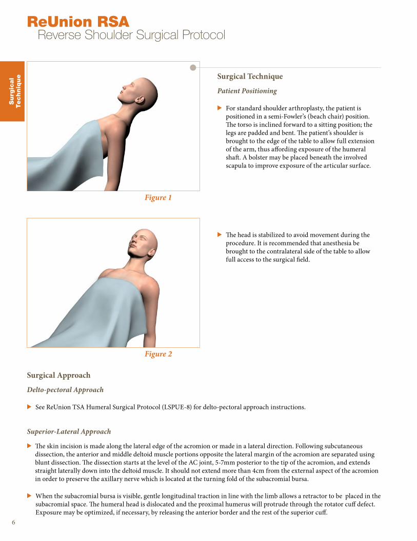
Patient Positioning
> For standard shoulder arthroplasty, the patient is positioned in a semi-Fowler’s (beach chair) position. The torso is inclined forward to a sitting position; the legs are padded and bent. The patient’s shoulder is brought to the edge of the table to allow full extension of the arm, thus affording exposure of the humeral shaft. A bolster may be placed beneath the involved scapula to improve exposure of the articular surface.
> The head is stabilized to avoid movement during the procedure. It is recommended that anesthesia be brought to the contralateral side of the table to allow full access to the surgical field.
Figure 2
Figure 1
7
Figure 4
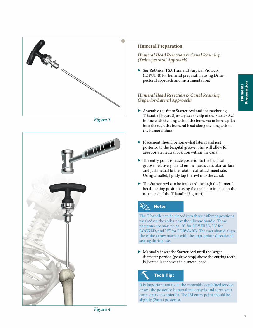
Figure 3
Humeral Preparation
Humeral Head Resection & Canal Reaming (Delto-pectoral Approach)
> See ReUnion TSA Humeral Surgical Protocol (LSPUE-8) for humeral preparation using Delto-pectoral approach and instrumentation.
Humeral Head Resection & Canal Reaming (Superior-Lateral Approach)
> Assemble the 6mm Starter Awl and the ratcheting T-handle [Figure 3] and place the tip of the Starter Awl in line with the long axis of the humerus to bore a pilot hole through the humeral head along the long axis of the humeral shaft.
> Placement should be somewhat lateral and just posterior to the bicipital groove. This will allow for appropriate neutral position within the canal.
> The entry point is made posterior to the bicipital groove, relatively lateral on the head’s articular surface and just medial to the rotator cuff attachment site. Using a mallet, lightly tap the awl into the canal.
> The Starter Awl can be impacted through the humeral head starting position using the mallet to impact on the metal pad of the T-handle [Figure 4].
> Manually insert the Starter Awl until the larger diameter portion (positive stop) above the cutting teeth is located just above the humeral head.
Note:
The T-handle can be placed into three different positions marked on the collar near the silicone handle. These positions are marked as “R” for REVERSE, “L” for LOCKED, and “F” for FORWARD. The user should align the white arrow marker with the appropriate directional setting during use.
Tech Tip:
It is important not to let the coracoid / conjoined tendon crowd the posterior humeral metaphysis and force your canal entry too anterior. The IM entry point should be slightly (2mm) posterior.
Hum
era
lP
repara
tion
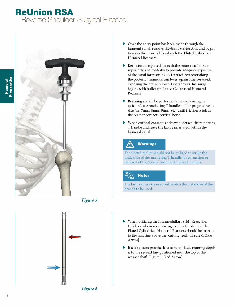
Figure 6
Figure 5
> Once the entry point has been made through the humeral canal, remove the 6mm Starter Awl, and begin to ream the humeral canal with the Fluted Cylindrical Humeral Reamers.
> Retractors are placed beneath the rotator cuff tissue superiorly and medially to provide adequate exposure of the canal for reaming. A Darrach retractor along the posterior humerus can lever against the coracoid, exposing the entire humeral metaphysis. Reaming begins with bullet-tip Fluted Cylindrical Humeral Reamers.
> Reaming should be performed manually using the quick release ratcheting T-handle and be progressive in size (i.e. 7mm, 8mm, 9mm, etc) until friction is felt as the reamer contacts cortical bone.
> When cortical contact is achieved, detach the ratcheting T-handle and leave the last reamer used within the humeral canal.
> When utilizing the intramedullary (IM) Resection Guide or whenever utilizing a cement restrictor, the Fluted Cylindrical Humeral Reamers should be inserted to the first line above the cutting teeth [Figure 6, Blue Arrow].
> If a long stem prosthesis is to be utilized, reaming depth is to the second line positioned near the top of the reamer shaft [Figure 6, Red Arrow].
Hum
era
lP
repara
tion
8
ReUnion RSA Reverse Shoulder Surgical Protocol
Warning:
The slotted mallet should not be utilized to strike the underside of the ratcheting T-handle for extraction or removal of the Starter Awl or cylindrical reamers.
Note:
The last reamer size used will match the distal size of the broach to be used.
Hum
era
lP
repara
tion
Figure 9
Figure 8
Figure 7
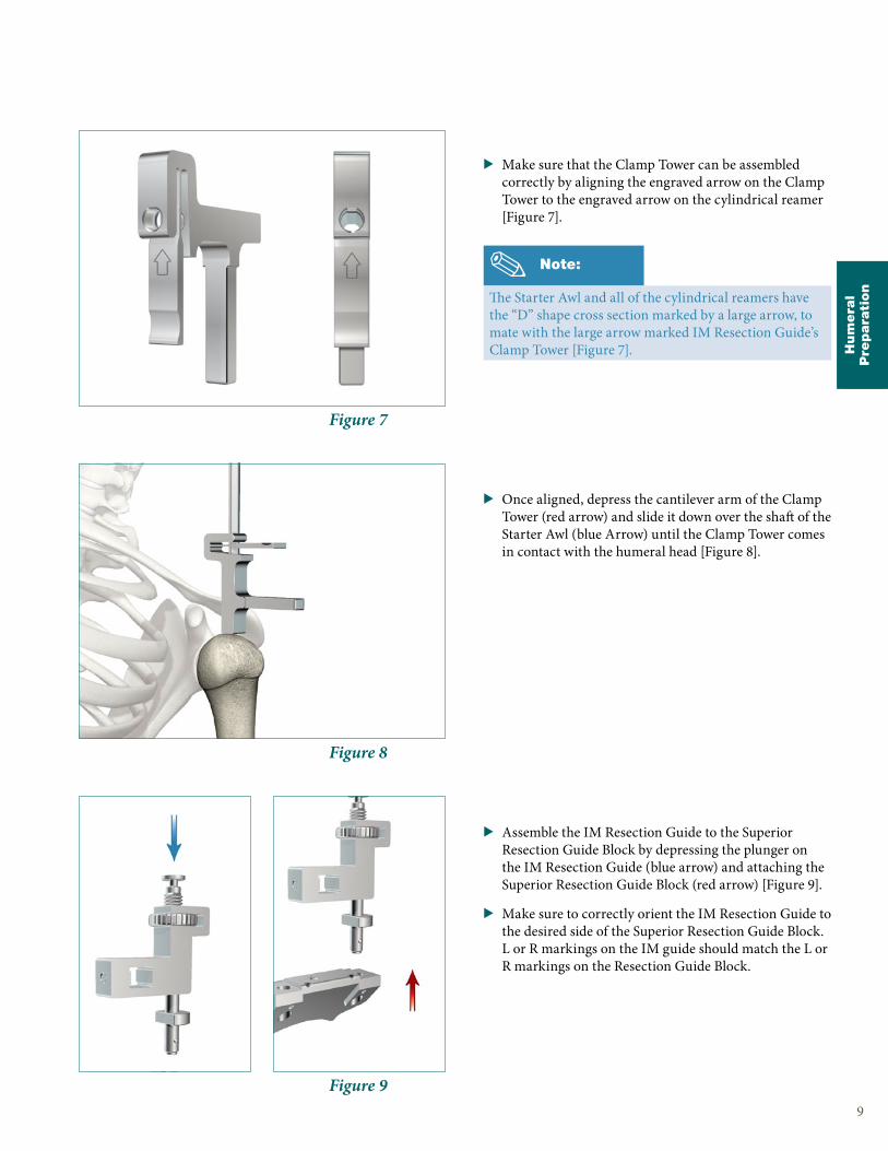
> Make sure that the Clamp Tower can be assembled correctly by aligning the engraved arrow on the Clamp Tower to the engraved arrow on the cylindrical reamer [Figure 7].
> Once aligned, depress the cantilever arm of the Clamp Tower (red arrow) and slide it down over the shaft of the Starter Awl (blue Arrow) until the Clamp Tower comes in contact with the humeral head [Figure 8].
> Assemble the IM Resection Guide to the Superior Resection Guide Block by depressing the plunger on the IM Resection Guide (blue arrow) and attaching the Superior Resection Guide Block (red arrow) [Figure 9].
> Make sure to correctly orient the IM Resection Guide to the desired side of the Superior Resection Guide Block. L or R markings on the IM guide should match the L or R markings on the Resection Guide Block.
9
Note:
The Starter Awl and all of the cylindrical reamers have the “D” shape cross section marked by a large arrow, to mate with the large arrow marked IM Resection Guide’s Clamp Tower [Figure 7].
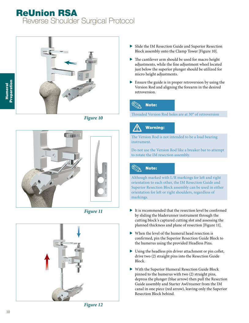
Figure 12
Figure 11
Figure 10
> Slide the IM Resection Guide and Superior Resection Block assembly onto the Clamp Tower [Figure 10].
> The cantilever arm should be used for macro height adjustments, while the fine adjustment wheel located just below the superior plunger should be utilized for micro height adjustments.
> Ensure the guide is in proper retroversion by using the Version Rod and aligning the forearm in the desired retroversion.
> It is recommended that the resection level be confirmed by sliding the bladerunner instrument through the cutting block’s captured cutting slot and assessing the planned thickness and plane of resection [Figure 11].
> When the level of the humeral head resection is confirmed, pin the Superior Resection Guide Block to the humerus using the provided Headless Pins.
> Using the headless pin driver attachment or pin collet, drive two (2) straight pins into the Resection Guide Block.
> With the Superior Humeral Resection Guide Block pinned to the humerus with two (2) straight pins, depress the plunger (blue arrow) then pull the Resection Guide assembly and Starter Awl/reamer from the IM canal in one piece (red arrow), leaving only the Superior Resection Block behind.
Hum
era
lP
repara
tion
10
ReUnion RSA Reverse Shoulder Surgical Protocol
Note:
Although marked with L/R markings for left and right orientation to each other, the IM Resection Guide and Superior Resection Block assembly can be used in either orientation for left or right shoulders, regardless of markings.
Warning:
The Version Rod is not intended to be a load bearing instrument.
Do not use the Version Rod like a breaker bar to attempt to rotate the IM resection assembly.
Note:
Threaded Version Rod holes are at 30° of retroversion

Hum
era
lP
repara
tion
11
Figure 13
> With only the Superior Humeral Resection Block in place, drive the third and final cross pin into the Superior Humeral Resection Block to secure it in place prior to starting the humeral resection.
> Place the saw blade through the captured cutting slot and begin to make the superior-lateral humeral head cut.
> Once the cut has been completed, remove the Headless Pins using the Headless Pin Removal Tool and then the Superior Humeral Resection Block.
See ReUnion TSA Humeral Surgical Protocol (LSPUE-8) for Humeral Stem preparation.
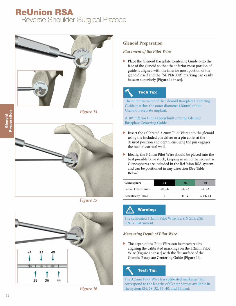
Figure 16
Figure 15
Figure 14
Glenoid Preparation
Placement of the Pilot Wire
> Place the Glenoid Baseplate Centering Guide onto the face of the glenoid so that the inferior most portion of guide is aligned with the inferior most portion of the glenoid itself and the “SUPERIOR” marking can easily be seen superiorly [Figure 14 inset].
> Insert the calibrated 3.2mm Pilot Wire into the glenoid using the included pin driver or a pin collet at the desired position and depth, ensuring the pin engages the medial cortical wall.
> Ideally, the 3.2mm Pilot Wire should be placed into the best possible bone stock, keeping in mind that eccentric Glenospheres are included in the ReUnion RSA system and can be positioned in any direction [See Table Below].
Measuring Depth of Pilot Wire
> The depth of the Pilot Wire can be measured by aligning the calibrated markings on the 3.2mm Pilot Wire [Figure 16 inset] with the flat surface of the Glenoid Baseplate Centering Guide [Figure 16].
Gle
noid
Pre
para
tion
12
ReUnion RSA Reverse Shoulder Surgical Protocol
Tech Tip:
The outer diameter of the Glenoid Baseplate Centering Guide matches the outer diameter (28mm) of the Glenoid Baseplate implant.
A 10° inferior tilt has been built into the Glenoid Baseplate Centering Guide.
Glenosphere 32 36 40
Lateral Offset (mm) +2, +6 +2, +6 +2, +6
Eccentricity (mm) 0 0, +2 0, +2, +4
Warning:
The calibrated 3.2mm Pilot Wire is a SINGLE USE ONLY instrument.
Tech Tip:
The 3.2mm Pilot Wire has calibrated markings that correspond to the lengths of Center Screws available in the system (24, 28, 32, 36, 40, and 44mm).

Gle
noid
Pre
para
tion
Figure 18
Figure 17
Reaming & Planing the Glenoid
> Select the appropriately sized Glenoid Reamer/Planar and assemble it to the Cannulated Straight Reamer Driver via a hex shaped quick connect feature [Figure 17].
13
Glenoid Reamer/Planar 32 36 40
Diameter (mm) 32 36 40
Note:
The Glenoid Reamer/Planars are designed to ream the glenoid face and plane the outer edge to receive the Glenoid Baseplate and Glenosphere implants.
Tech Tip:
If the user is uncertain at this step which Glenosphere size will be utilized, it is recommended that the largest size Glenoid Reamer/Planar be used that the patient’s anatomy will accommodate.
Note:
All of the Glenoid Reamer/Planars have the same radius of curvature; as long as the soft tissue permits, any of the reamer/planars can be used to prepare the glenoid implants.
Caution:
To ensure accuracy in reaming, apply power prior to the reamer/planar making contact with the lateral surface of the glenoid.
Figure 19
Caution:
During reaming, make sure to use the power instruments in “REAM” mode or be sure to utilize reamer specific attachments for proper RPM and torque settings.
> With the calibrated 3.2mm Pilot Wire in place, position the Glenoid Reamer/Planar over the top of the 3.2mm Pilot Wire and begin to ream the glenoid face utilizing a pulsing method [Figure 19].

Gle
noid
Pre
para
tion
14
ReUnion RSA Reverse Shoulder Surgical Protocol
Glenosphere 32 36 40
Lateral Offset (mm) +2, +6 +2, +6 +2, +6
Eccentricity (mm) 0 0, +2 0, +2, +4
> Pulse ream the glenoid to the desired level, ensuring that the medial geometry of the Glenoid Baseplate is completely reamed and contained inside the glenoid.
Caution:
There is no stop on the glenoid reamer, so continual attention to reaming depth is important.
A full awareness of the patient’s existing glenoid deformity/version prior to reaming is necessary to determine the amount of correction necessary for effective glenoid implantation.
Note:
Due to the included 10° inferior tilt in the Glenoid Baseplate Centering Guide, inferior reaming should be evident first. Superior reaming should then follow.
> It is critical that the glenoid is adequately reamed to ensure complete seating of the Glenoid Baseplate. Ream to expose subchondral bone.
> Continue reaming to expose the subchondral bone on the inferior 50% of the prepared glenoid until bleeding bone is exposed and the entire circumference of the Glenoid Reamer/Planar has made contact with the glenoid face.
Figure 21
> If using an eccentric Glenosphere [See table below], after standard glenoid reaming has been completed, be sure to use the included eccentric glenoid planar [Figure 21] to ensure the eccentric Glenosphere can be properly seated to the Glenoid Baseplate without any interference from the backside of the Glenosphere.
> Prior to Pilot Wire removal, take note of and record the depth/length of the Pilot Wire as measured in a previous step.
Figure 20
Gle
noid
Pre
para
tion
15
Figure 23
Figure 22
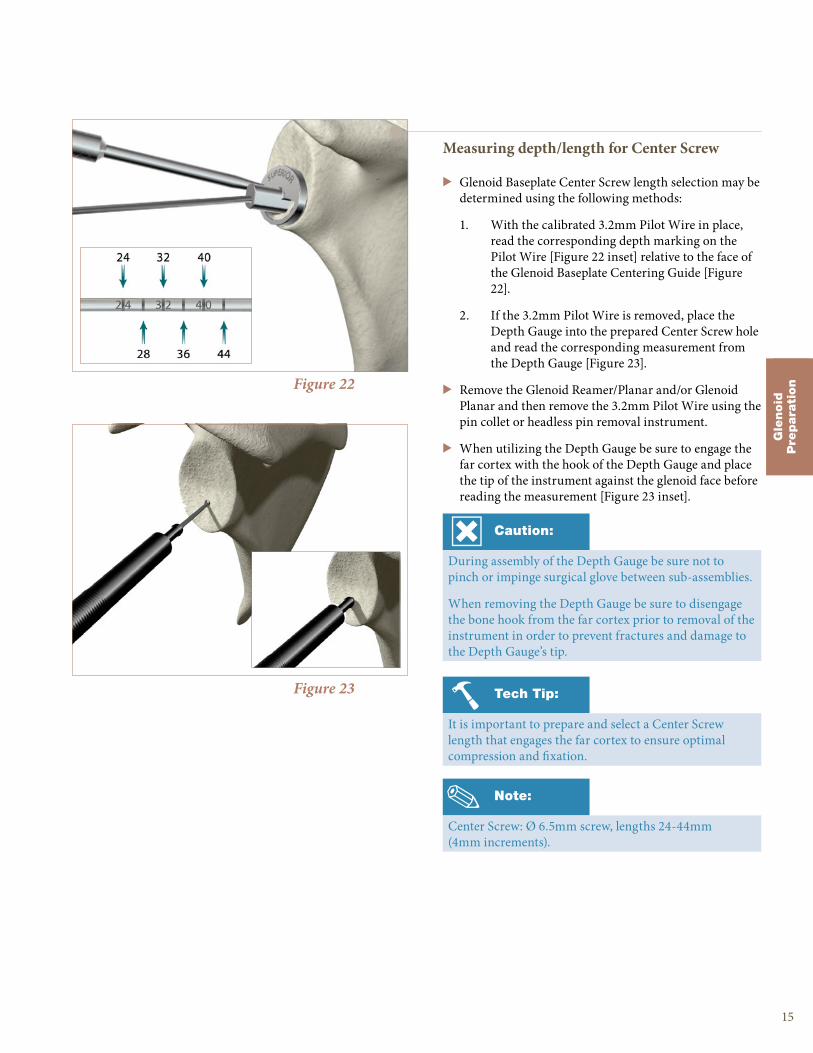
Measuring depth/length for Center Screw
> Glenoid Baseplate Center Screw length selection may be determined using the following methods:
1. With the calibrated 3.2mm Pilot Wire in place, read the corresponding depth marking on the Pilot Wire [Figure 22 inset] relative to the face of the Glenoid Baseplate Centering Guide [Figure 22].
2. If the 3.2mm Pilot Wire is removed, place the Depth Gauge into the prepared Center Screw hole and read the corresponding measurement from the Depth Gauge [Figure 23].
> Remove the Glenoid Reamer/Planar and/or Glenoid Planar and then remove the 3.2mm Pilot Wire using the pin collet or headless pin removal instrument.
> When utilizing the Depth Gauge be sure to engage the far cortex with the hook of the Depth Gauge and place the tip of the instrument against the glenoid face before reading the measurement [Figure 23 inset].
Note:
Center Screw: Ø 6.5mm screw, lengths 24-44mm (4mm increments).
Caution:
During assembly of the Depth Gauge be sure not to pinch or impinge surgical glove between sub-assemblies.
When removing the Depth Gauge be sure to disengage the bone hook from the far cortex prior to removal of the instrument in order to prevent fractures and damage to the Depth Gauge’s tip.
Tech Tip:
It is important to prepare and select a Center Screw length that engages the far cortex to ensure optimal compression and fixation.
Gle
noid
Pre
para
tion
16
ReUnion RSA Reverse Shoulder Surgical Protocol
Figure 26
Figure 25
Figure 24
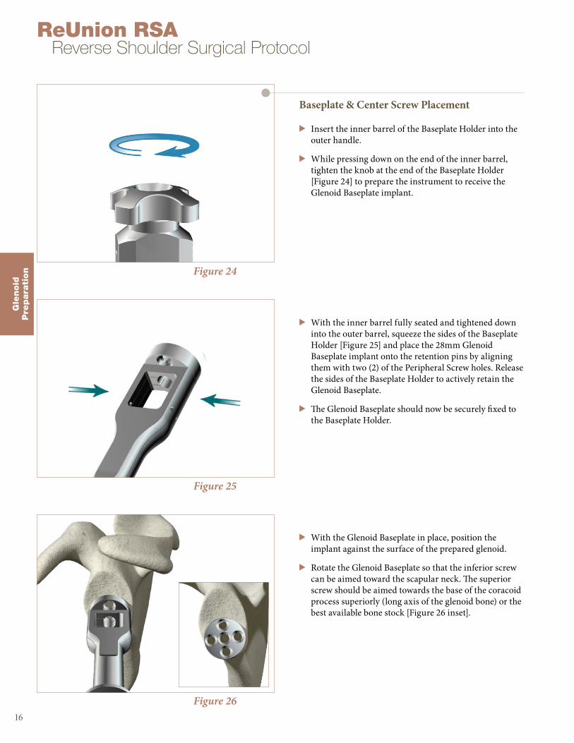
Baseplate & Center Screw Placement
> Insert the inner barrel of the Baseplate Holder into the outer handle.
> While pressing down on the end of the inner barrel, tighten the knob at the end of the Baseplate Holder [Figure 24] to prepare the instrument to receive the Glenoid Baseplate implant.
> With the inner barrel fully seated and tightened down into the outer barrel, squeeze the sides of the Baseplate Holder [Figure 25] and place the 28mm Glenoid Baseplate implant onto the retention pins by aligning them with two (2) of the Peripheral Screw holes. Release the sides of the Baseplate Holder to actively retain the Glenoid Baseplate.
> The Glenoid Baseplate should now be securely fixed to the Baseplate Holder.
> With the Glenoid Baseplate in place, position the implant against the surface of the prepared glenoid.
> Rotate the Glenoid Baseplate so that the inferior screw can be aimed toward the scapular neck. The superior screw should be aimed towards the base of the coracoid process superiorly (long axis of the glenoid bone) or the best available bone stock [Figure 26 inset].

Tech Tip:
The tip of the T25 driver is tapered slightly, providing self-retention of the screw to the driver.
Gle
noid
Pre
para
tion
17
Figure 28
Figure 27
> Assemble the Center Screw T25 driver to the 4-sided ratcheting handle [Figure 27]
> Once assembled, the Center Screw T25 driver should be securely engaged into the 4-Sided Handle and ready for use.
Figure 29
Note:
It is important to prepare and select a Center Screw length that engages the far cortex to ensure optimal compression and fixation.
> The intent of Center Screw placement should be to compress the Glenoid Baseplate onto the face of the glenoid and achieve a bi-cortical lock.
> Taking note of the measurements taken either with the calibrated Guide Pin or the Depth Gauge, select the appropriate length screw and verify its length with the Screw Identification Tool built into the case/tray [Figure 28].
> Place the selected Center Screw into the opening on the end of the Baseplate Holder and allow it to slide down into position on top of the Glenoid Baseplate [Figure 29].
Tech Tip:
A correctly seated Center Screw will provide the best baseplate compression and fixation. This will also ensure the correct seating of the Glenosphere to the Glenoid Baseplate.
Tech Tip:
The selected Center Screw may also be loaded onto the Center Screw T25 driver prior to insertion into the Baseplate Holder.

Figure 31
Figure 30
> Apply an axial force towards the face of the glenoid [Figure 30] while holding the Baseplate Holder firmly in place to prevent rotation of the Glenoid Baseplate.
> With the Center Screw T25 driver securely attached to the Center Screw within the Baseplate Holder, begin to tighten down the Center Screw into the glenoid fossa.
> When fully seated, the Glenoid Baseplate should sit flush with the glenoid face and the scapula should rotate slightly when attempting to tighten the Center Screw further onto the glenoid face.
Gle
noid
Pre
para
tion
18
ReUnion RSA Reverse Shoulder Surgical Protocol
Warning:
Once the Center Screw is locked into position DO NOT turn the Glenoid Baseplate handle to reposition or rotate the baseplate [Figure 31].
Tech Tip:
If the Glenoid Baseplate does not compress when using the selected screw, double check the measurement using the Depth Gauge and ensure that the far cortex can be captured using the appropriate length screw.
Caution:
Once the Center Screw is fully seated in the baseplate, do not over-tighten the Center Screw.
Warning:
It is important to ensure the screw driver and screw are parallel with each other and the tip of the T25 driver is fully engaged in the screw head.
The screws and drivers should only be manually driven and never used under power.
Deviation from this technique may lead to stripping of the driver and screw interface.

Gle
noid
Pre
para
tion
Figure 33
Figure 32
> Remove the Baseplate Holder from the now locked Glenoid Baseplate by loosening the knob in a counter clockwise direction [Figure 32].
> After the Center Screw has been properly locked into position on the Glenoid Baseplate, a visual inspection of the Glenoid Baseplate should be performed to confirm there are no gaps between the reamed surface and the Glenoid Baseplate.
19
Tech Tip:
A correctly seated Center Screw will provide the best Glenoid Baseplate compression and fixation. This will also ensure the correct seating of the Glenosphere to the Glenoid Baseplate.

Preparation for Peripheral Screw Placement
Inferior Screw
> Place the Variable Angle Peripheral Drill Guide into the Glenoid Baseplate’s inferior hole. The drill guide can be angled up to a maximum angle of ±15° but should always be engaged fully in the Glenoid Baseplate hole.
> If possible, palpate the scapular neck and aim into the best possible bone, as close to the lateral border of the scapula as permitted.
Figure 34
Gle
noid
Pre
para
tion
20
ReUnion RSA Reverse Shoulder Surgical Protocol
Note:
The locking Peripheral Screws are designed to allow a maximum angulation of up to ±15° for optimal screw placement.
Peripheral Screws: Ø 4.5mm screw, lengths 16-52mm (4mm increments).
Figure 35
Tech Tip:
Axial pressure should be maintained on the drill guide throughout the entire drilling process to ensure proper seating of the drill guide to the baseplate.
Tech Tip:
A separate fixed angled drill guide is included and can be utilized to place Peripheral Screws in a perpendicular configuration to the Glenoid Baseplate.
> While firmly holding the Peripheral Drill Guide against the Glenoid Baseplate, begin drilling through the subchondral bone to the desired optimal depth using the 3.1mm drill bit.
> Redirect and re-drill as needed to achieve optimal Peripheral Screw trajectory and bone purchase.
Caution:
Care must be taken during the drilling process in order to preserve as much bone as possible for screw purchase.
Warning:
The 3.1mm drill bit is a SINGLE USE ONLY instrument.
Do not use the drill bit outside of the provided Peripheral Drill Guides during Peripheral Screw preparation.
Gle
noid
Pre
para
tionFigure 36
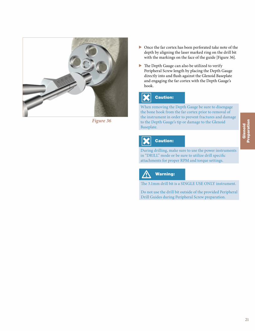
> Once the far cortex has been perforated take note of the depth by aligning the laser marked ring on the drill bit with the markings on the face of the guide [Figure 36].
> The Depth Gauge can also be utilized to verify Peripheral Screw length by placing the Depth Gauge directly into and flush against the Glenoid Baseplate and engaging the far cortex with the Depth Gauge’s hook.
21
Caution:
When removing the Depth Gauge be sure to disengage the bone hook from the far cortex prior to removal of the instrument in order to prevent fractures and damage to the Depth Gauge’s tip or damage to the Glenoid Baseplate.
Caution:
During drilling, make sure to use the power instruments in “DRILL” mode or be sure to utilize drill specific attachments for proper RPM and torque settings.

Figure 39
Figure 38
Peripheral Screw Placement
> The intent of Peripheral Screw placement should be to engage the maximum amount of good quality bone stock available with the appropriate length screws.
> Taking note of the measurements taken either with the peripheral drill guide or the Depth Gauge, select the appropriate length screw and verify its length with the screw identification tool built into the case/tray [Figure 37].
> Assemble the Peripheral Screw T25 driver to the 4-sided ratcheting handle and engage onto the selected inferior Peripheral Screw.
> Place the selected inferior Peripheral Screw into the Glenoid Baseplate and begin to manually tighten the Peripheral Screw.
> The head of the Peripheral Screw should be below the level of the surface of the baseplate when it is fully engaged and locked in place.
> Repeat above steps for opposing superior screw and then the anterior and posterior screws.
Gle
noid
Pre
para
tion
22
ReUnion RSA Reverse Shoulder Surgical Protocol
Warning:
It is important to ensure the screw driver and screw are parallel with each other and fully engaged as you insert the screws.
The screws and drivers should only be manually driven and never used under power.
Deviation from this technique may lead to stripping of the driver and screw interface. Once the screws are fully seated in the baseplate, do not over-tighten.
Note:
Make sure the Peripheral Screw is taper locked to the Peripheral Screw T25 driver before handling the assembly.
Figure 37
Tech Tip:
The required minimum number of screws shall be no less than two (2) Peripheral Screws (superior and inferior) and one (1) Center Screw.
When possible, four (4) Peripheral and one (1) Center Screw should be used.
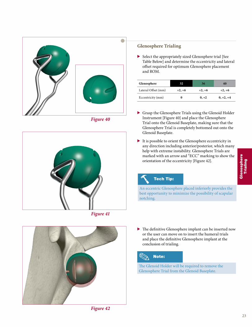
Figure 42
Figure 41
Figure 40
Glenosphere Trialing
> Select the appropriately sized Glenosphere trial [See Table Below] and determine the eccentricity and lateral offset required for optimum Glenosphere placement and ROM.
> Grasp the Glenosphere Trials using the Glenoid Holder Instrument [Figure 40] and place the Glenosphere Trial onto the Glenoid Baseplate, making sure that the Glenosphere Trial is completely bottomed out onto the Glenoid Baseplate.
> It is possible to orient the Glenosphere eccentricity in any direction including anterior/posterior, which many help with extreme instability. Glenosphere Trials are marked with an arrow and “ECC” marking to show the orientation of the eccentricity [Figure 42].
> The definitive Glenosphere implant can be inserted now or the user can move on to insert the humeral trials and place the definitive Glenosphere implant at the conclusion of trialing.
23
Note:
The Glenoid Holder will be required to remove the Glenosphere Trial from the Glenoid Baseplate.
Glenosphere 32 36 40
Lateral Offset (mm) +2, +6 +2, +6 +2, +6
Eccentricity (mm) 0 0, +2 0, +2, +4
Gle
nosp
here
Tri
aling
Tech Tip:
An eccentric Glenosphere placed inferiorly provides the best opportunity to minimize the possibility of scapular notching.
24
ReUnion RSA Reverse Shoulder Surgical Protocol
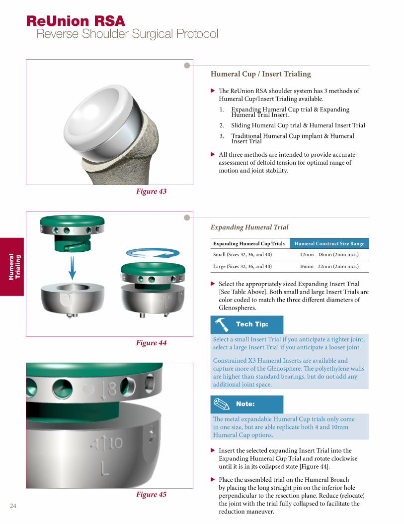
Expanding Humeral Cup Trials Humeral Construct Size Range
Small (Sizes 32, 36, and 40) 12mm - 18mm (2mm incr.)
Large (Sizes 32, 36, and 40) 16mm - 22mm (2mm incr.)
Figure 45
Figure 44
Figure 43
Humeral Cup / Insert Trialing
> The ReUnion RSA shoulder system has 3 methods of Humeral Cup/Insert Trialing available.
1. Expanding Humeral Cup trial & Expanding Humeral Trial Insert.
2. Sliding Humeral Cup trial & Humeral Insert Trial
3. Traditional Humeral Cup implant & Humeral Insert Trial
> All three methods are intended to provide accurate assessment of deltoid tension for optimal range of motion and joint stability.
Hum
era
lT
rialing
Note:
The metal expandable Humeral Cup trials only come in one size, but are able replicate both 4 and 10mm Humeral Cup options.
Tech Tip:
Select a small Insert Trial if you anticipate a tighter joint; select a large Insert Trial if you anticipate a looser joint.
Constrained X3 Humeral Inserts are available and capture more of the Glenosphere. The polyethylene walls are higher than standard bearings, but do not add any additional joint space.
> Insert the selected expanding Insert Trial into the Expanding Humeral Cup Trial and rotate clockwise until it is in its collapsed state [Figure 44].
> Place the assembled trial on the Humeral Broach by placing the long straight pin on the inferior hole perpendicular to the resection plane. Reduce (relocate) the joint with the trial fully collapsed to facilitate the reduction maneuver.
Expanding Humeral Trial
> Select the appropriately sized Expanding Insert Trial [See Table Above]. Both small and large Insert Trials are color coded to match the three different diameters of Glenospheres.

25
Hum
era
lT
rialing
Figure 47
Figure 46
> Perform an initial reduction with the collapsed trial, making sure to minimize the amount of tension on the deltoid.
> As the trial is expanded and tension placed on the deltoid, the markings will correspond to the Humeral Cup and Humeral Insert thicknesses.
> In the example provided in Figure 45 & 46, a 8mm thick X3 Humeral Insert would be used with a 10mm thick Humeral Cup, in a left (L) shoulder.
> Using the unthreaded portion of the Version Rod, expand the Expanding Insert Trial until the entire construct begins to apply tension to the deltoid.
> Progressively expand the trial with the shoulder reduced by turning the Expanding Trial counterclockwise. Each turn will increase the thickness of the construct by 2mm.
> The trial reduction should show very limited distraction (1mm or less). In cases of extreme instability, constrained humeral bearings are available.
> Constrained X3 Humeral Inserts capture more of the Glenosphere and have polyethylene walls which are higher than the standard X3 Humeral Insert implants, but do not add any additional joint space.
> If the appropriate amount of tension is achieved for optimal range of motion, the component size markings on the lateral aspect of the Expanding Trial construct should be recorded for final prosthesis selection.
> Prior to removal, the Expanding Trial should be compressed back to its original state, releasing the tension from the deltoid so that the instrument can be removed easily.
Warning:
Do not overly tension the deltoid as this may cause damage to bone and soft tissue.
Note:
The top number represents the Humeral Insert thickness (mm). The bottom numbers (4 and 10) represent the Humeral Cup thickness (mm). The L or R represent which side shoulder is being trialed.
Figure 48
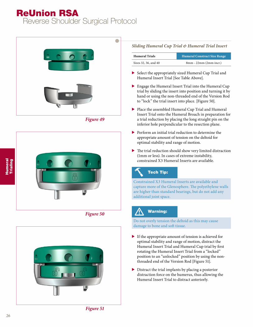
Figure 50
Figure 49
Sliding Humeral Cup Trial & Humeral Trial Insert
> Select the appropriately sized Humeral Cup Trial and Humeral Insert Trial [See Table Above].
> Engage the Humeral Insert Trial into the Humeral Cup trial by sliding the insert into position and turning it by hand or using the non-threaded end of the Version Rod to “lock” the trial insert into place. [Figure 50].
> Place the assembled Humeral Cup Trial and Humeral Insert Trial onto the Humeral Broach in preparation for a trial reduction by placing the long straight pin on the inferior hole perpendicular to the resection plane.
> Perform an initial trial reduction to determine the appropriate amount of tension on the deltoid for optimal stability and range of motion.
> The trial reduction should show very limited distraction (1mm or less). In cases of extreme instability, constrained X3 Humeral Inserts are available.
Hum
era
lT
rialing
26
ReUnion RSA Reverse Shoulder Surgical Protocol
Warning:
Do not overly tension the deltoid as this may cause damage to bone and soft tissue.
Humeral Trials Humeral Construct Size Range
Sizes 32, 36, and 40 8mm - 22mm (2mm incr.)
Figure 51
> If the appropriate amount of tension is achieved for optimal stability and range of motion, distract the Humeral Insert Trial and Humeral Cup trial by first rotating the Humeral Insert Trial from a “locked” position to an “unlocked” position by using the non-threaded end of the Version Rod [Figure 51].
> Distract the trial implants by placing a posterior distraction force on the humerus, thus allowing the Humeral Insert Trial to distract anteriorly.
Tech Tip:
Constrained X3 Humeral Inserts are available and capture more of the Glenosphere. The polyethylene walls are higher than standard bearings, but do not add any additional joint space.

Hum
era
lT
rialing
Figure 53
Figure 52
27
Note:
For assemblies of 14mm and 16mm, it is recommended to use the thicker metal Humeral Cup component versus a thicker X3 Humeral Insert.
Traditional Humeral Trialing
(Humeral Trial Insert & Humeral Cup Implant)
> With the definitive Humeral Cup locked to the Humeral Stem, placed the selected Humeral Insert Trial into the definitive Humeral Cup and reduce the joint [Figure 52].
Humeral Cup Trials Humeral Construct Size Range
Sizes 32, 36, and 40 8mm - 22mm (2mm incr.)
Component Size Selection
> The ReUnion RSA Reverse Shoulder System comes with a large range of implant sizes to accommodate all ranges of glenohumeral instability and/or rotator cuff deficiency.
> If the appropriate amount of tension is achieved for optimal stability and range of motion, distract the joint and extract the Humeral Insert Trial from the definitive Humeral Cup.
X3 Humeral Inserts4 6 8 10 12
Humeral Cup
4 8 10 12 14 1610 14 16 18 20 22

28
ReUnion RSA Reverse Shoulder Surgical Protocol
Figure 56
Figure 55
Figure 54
Glenosphere Placement
> Engage the desired definitive Glenosphere on the Glenosphere Holder/Impactor and place the Glenosphere onto the Glenoid Baseplate [Figure 54].
> If using an eccentric Glenosphere, use the eccentric alignment mark on the Glenosphere Impactor Tip and align it to the laser mark on the underside of the eccentric Glenosphere to place the Glenosphere in the optimum orientation as trialed.
> Prior to impaction, make sure the Glenosphere is properly aligned to the Glenoid Baseplate and Center Screw.
> Definitively seat the Glenosphere by placing several sharp blows on the Glenosphere Holder/Impactor. A set screw is not needed to attach the Glenosphere to the Glenoid Baseplate.
> The design of the Morse taper provides a secure mode of fixation. Check the Glenosphere to make sure it is fully seated after impaction.
> To detach the Glenosphere Holder/Impactor from the Glenosphere after it has been impacted in place, unthread the instrument counter-clockwise until it is free [Figure 55].
> After the removal of the Glenosphere Holder/Impactor, inspect the Glenosphere for placement and clean the articulating surface of all debris.
Note:
It is critical to ensure that all tapers are clean, dry and clear of any debris or damage prior to assembling the Glenosphere to the Glenoid Baseplate.
Fin
al
Impla
nts
Caution:
The attachment between the Glenosphere Holder/Impactor and Glenosphere happens via a threaded connector. Care should be taken to make sure the axis of the instrument is parallel to the axis of the implant to avoid cross threading.
Warning:
Excessive impaction on a properly seated Humeral Stem may potentially cause a fracture of the medial calcar or humeral shaft.
Fin
al
Impla
nts
29
Figure 59
Figure 58
Figure 57
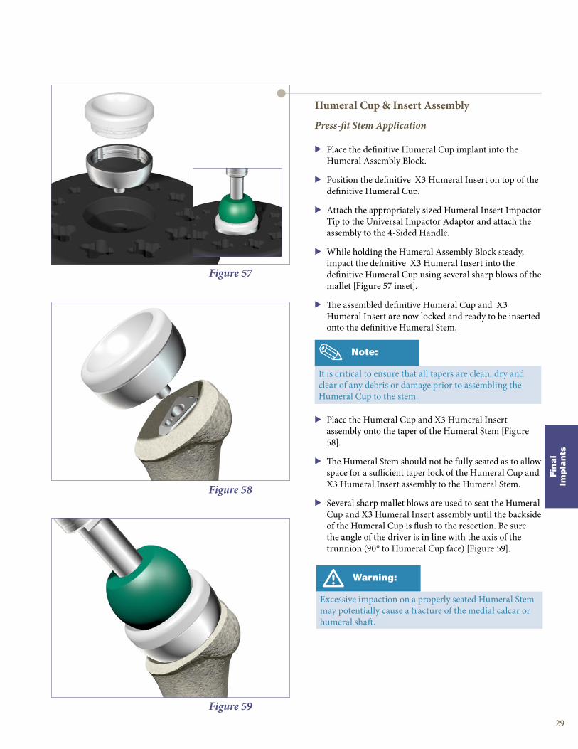
Humeral Cup & Insert Assembly
Press-fit Stem Application
> Place the definitive Humeral Cup implant into the Humeral Assembly Block.
> Position the definitive X3 Humeral Insert on top of the definitive Humeral Cup.
> Attach the appropriately sized Humeral Insert Impactor Tip to the Universal Impactor Adaptor and attach the assembly to the 4-Sided Handle.
> While holding the Humeral Assembly Block steady, impact the definitive X3 Humeral Insert into the definitive Humeral Cup using several sharp blows of the mallet [Figure 57 inset].
> The assembled definitive Humeral Cup and X3 Humeral Insert are now locked and ready to be inserted onto the definitive Humeral Stem.
> Place the Humeral Cup and X3 Humeral Insert assembly onto the taper of the Humeral Stem [Figure 58].
> The Humeral Stem should not be fully seated as to allow space for a sufficient taper lock of the Humeral Cup and X3 Humeral Insert assembly to the Humeral Stem.
> Several sharp mallet blows are used to seat the Humeral Cup and X3 Humeral Insert assembly until the backside of the Humeral Cup is flush to the resection. Be sure the angle of the driver is in line with the axis of the trunnion (90° to Humeral Cup face) [Figure 59].
Note:
It is critical to ensure that all tapers are clean, dry and clear of any debris or damage prior to assembling the Humeral Cup to the stem.
Fin
al
Impla
nts
30
ReUnion RSA Reverse Shoulder Surgical Protocol
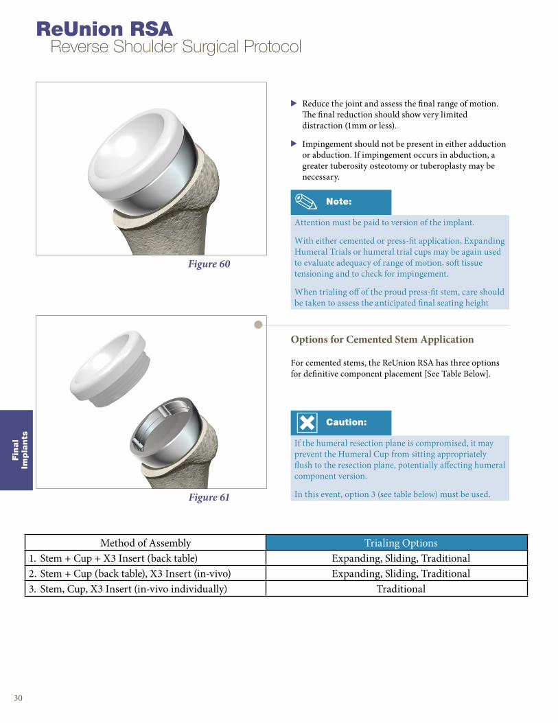
Note:
Attention must be paid to version of the implant.
With either cemented or press-fit application, Expanding Humeral Trials or humeral trial cups may be again used to evaluate adequacy of range of motion, soft tissue tensioning and to check for impingement.
When trialing off of the proud press-fit stem, care should be taken to assess the anticipated final seating height
Figure 60
> Reduce the joint and assess the final range of motion. The final reduction should show very limited distraction (1mm or less).
> Impingement should not be present in either adduction or abduction. If impingement occurs in abduction, a greater tuberosity osteotomy or tuberoplasty may be necessary.
Figure 61
Options for Cemented Stem Application
For cemented stems, the ReUnion RSA has three options for definitive component placement [See Table Below].
Caution:
If the humeral resection plane is compromised, it may prevent the Humeral Cup from sitting appropriately flush to the resection plane, potentially affecting humeral component version.
In this event, option 3 (see table below) must be used.
Method of Assembly Trialing Options1. Stem + Cup + X3 Insert (back table) Expanding, Sliding, Traditional2. Stem + Cup (back table), X3 Insert (in-vivo) Expanding, Sliding, Traditional3. Stem, Cup, X3 Insert (in-vivo individually) Traditional

Fin
al
Impla
nts
31
Figure 64
Figure 63
Figure 62
Option 1: Complete Back Table Assembly & Monoblock Insertion
> Place the definitive Humeral Cup implant into the Humeral Assembly Block.
> Position the definitive X3 Humeral Insert on top of the definitive Humeral Cup [Figure 62].
> Attach the appropriately sized Humeral Insert impactor tip to the Universal Impactor Adaptor and attach the assembly to the 4-Sided Handle.
> While holding the Humeral Assembly Block steady, impact the definitive X3 Humeral Insert into the definitive Humeral Cup using several sharp blows of the mallet [Figure 62 inset].
> The assembled definitive Humeral Cup and X3 Humeral Insert are now locked and ready to be inserted onto the definitive Humeral Stem.
> Place the definitive Humeral Stem into the correct position on the marked Humeral Assembly Block.
> While holding the Humeral Assembly Block steady, impact the Humeral Cup and X3 Humeral Insert assembly into the Humeral Stem using several sharp blows to lock the assembly. Be sure the angle of the driver is in line with the axis of the trunnion (90° to Humeral Cup face).
> The monoblock assembly (Humeral Stem, Humeral Cup, and X3 Humeral Insert) is now ready to be inserted into the cement mantle.
> Insert the monoblock assembly into the cement mantle. Surgeon must ensure that the back surface of the Humeral Cup is flush to the resection plane [Figure 64].
> Reduce the joint and assess the final range of motion. The final reduction should show very limited distraction (1mm or less).
> Impingement should not be present in either adduction or abduction. If impingement occurs in abduction, a greater tuberosity osteotomy or tuberoplasty may be necessary.
Caution:
Prior to monoblock insertion into the cement mantle, surgeon must inspect the resection plane to ensure the Humeral Cup can be seated flush to the resection.

Figure 67
Figure 66
Figure 65
Option 2: Back Table Assembly of the Humeral Cup & Cemented Stem
> Place the definitive Humeral Stem into the correct position on the marked Humeral Assembly Block.
> Position the definitive Humeral Cup onto the definitive Humeral Stem.
> Attach the Universal Impactor Tip to the Universal Impactor Adaptor and attach the assembly to the 4-Sided Handle.
> While holding the Humeral Assembly Block steady, impact the Humeral Cup into the Humeral Stem using several sharp blows to lock the Humeral Cup into the Humeral Stem. Be sure the angle of the driver is in line with the axis of the trunnion (90° to Humeral Cup face).
> The monoblock assembly (Humeral Stem and Humeral Cup) is now ready to be inserted into the cement mantle.
> Insert the monoblock assembly into the cement mantle. Surgeon must ensure that the back surface of the Humeral Cup is flush to the resection plane [Figure 66].
> Place the definitive X3 Humeral Insert selected during trialing onto the Humeral Cup.
> Attach the appropriately sized Humeral Insert Impactor Tip to the 4-Sided Handle.
> Apply several sharp mallet blows to lock the X3 Humeral Insert to the Humeral Cup. Be sure the angle of the driver is in line with the axis of the trunnion (90° to Humeral Cup face).
> Reduce the joint and assess the final range of motion. The final reduction should show very limited distraction (1mm or less).
> Impingement should not be present in either adduction or abduction. If impingement occurs in abduction, a greater tuberosity osteotomy or tuberoplasty may be necessary.
ReUnion RSA Reverse Shoulder Surgical Protocol
Caution:
Prior to monoblock insertion into the cement mantle, surgeon must inspect the resection plane to ensure the Humeral Cup can be seated flush to the resection.
Fin
al
Impla
nts
32
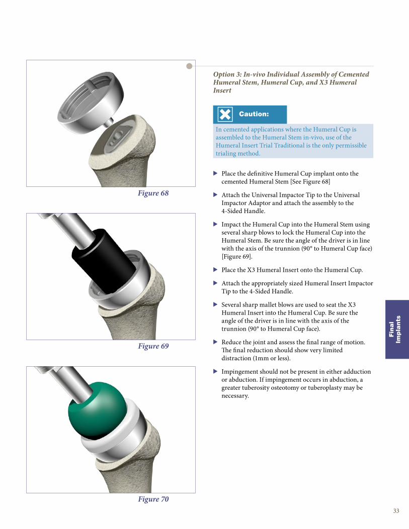
Figure 70
Figure 69
Figure 68
Option 3: In-vivo Individual Assembly of Cemented Humeral Stem, Humeral Cup, and X3 Humeral Insert
> Place the definitive Humeral Cup implant onto the cemented Humeral Stem [See Figure 68]
> Attach the Universal Impactor Tip to the Universal Impactor Adaptor and attach the assembly to the 4-Sided Handle.
> Impact the Humeral Cup into the Humeral Stem using several sharp blows to lock the Humeral Cup into the Humeral Stem. Be sure the angle of the driver is in line with the axis of the trunnion (90° to Humeral Cup face) [Figure 69].
> Place the X3 Humeral Insert onto the Humeral Cup.
> Attach the appropriately sized Humeral Insert Impactor Tip to the 4-Sided Handle.
> Several sharp mallet blows are used to seat the X3 Humeral Insert into the Humeral Cup. Be sure the angle of the driver is in line with the axis of the trunnion (90° to Humeral Cup face).
> Reduce the joint and assess the final range of motion. The final reduction should show very limited distraction (1mm or less).
> Impingement should not be present in either adduction or abduction. If impingement occurs in abduction, a greater tuberosity osteotomy or tuberoplasty may be necessary.
Caution:
In cemented applications where the Humeral Cup is assembled to the Humeral Stem in-vivo, use of the Humeral Insert Trial Traditional is the only permissible trialing method.
Fin
al
Impla
nts
33

Figure 72
Figure 71
Component Removal
Humeral Poly Insert Removal
> Dislocate the glenohumeral joint so that the X3 Humeral Insert is exposed.
> Use the 3.1mm Drill Bit and drill a pilot hole into the X3 Humeral Insert at an oblique angle.
> Drive the 3.1mm drill bit to the flat bottom surface of the Humeral Cup away from the sides and the locking features of the X3 Humeral Insert.
> Assemble the Polyethylene Removal Tool to the 4-Sided Handle and introduce the tip of the Polyethylene Removal Tool into the prepared pilot hole at the same oblique angle.
> Drive the Polyethylene Removal Tool into the X3 Humeral Insert until the insert disassociates from the Humeral Cup.
Figure 73
Humeral Cup Removal
> Attach the Forked Removal Tool to the 4-Sided Handle and slide the Forked Removal Tool under the Humeral Cup.
> Align the Forked Removal Tool to the neck of the Humeral Cup and lightly tap the Forked Removal Tool in with a mallet to mechanically disassociate the Humeral Cup from the Humeral Stem.
> If the Humeral Cup is in direct contact with the bone, the surgeon may need to create a small window along the edge of the resection to obtain access for insertion of the fork.
Note:
After the X3 Humeral Insert has been removed, make sure that the joint space is completely clean and clear of any and all debris and polyethylene particles.
34
ReUnion RSA Reverse Shoulder Surgical Protocol
Impla
nt
Rem
ova
l
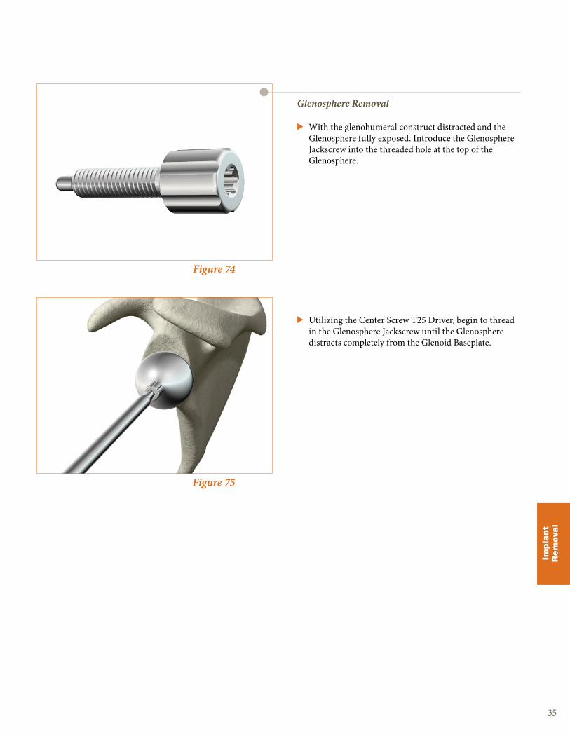
Figure 75
Figure 74
Glenosphere Removal
> With the glenohumeral construct distracted and the Glenosphere fully exposed. Introduce the Glenosphere Jackscrew into the threaded hole at the top of the Glenosphere.
> Utilizing the Center Screw T25 Driver, begin to thread in the Glenosphere Jackscrew until the Glenosphere distracts completely from the Glenoid Baseplate.
35
Impla
nt
Rem
ova
l

Warning:
Do not toggle the Glenoid Reamer/Planar during disassembly as this has the potential to compromise the fit of the quick connect mechanism [Figure 77 inset].
Figure 76
Disassembly of Glenoid Reamer/Planar
> The recommended method to disassemble the Glenoid Reamer/Planars from the Cannulated Straight Reamer Driver is by utilizing the Glenoid Holder to grasp around the circumference of the Glenoid Reamer/Planar.
> By holding the reamer/planar face as shown [Figure 77] with the glenoid holder, pull the Glenoid Reamer/Planar face away from Cannulated Straight Reamer Driver in an axial direction to disengage the quick connect feature.
Figure 7736
ReUnion RSA Reverse Shoulder Surgical Protocol
Appendic
es
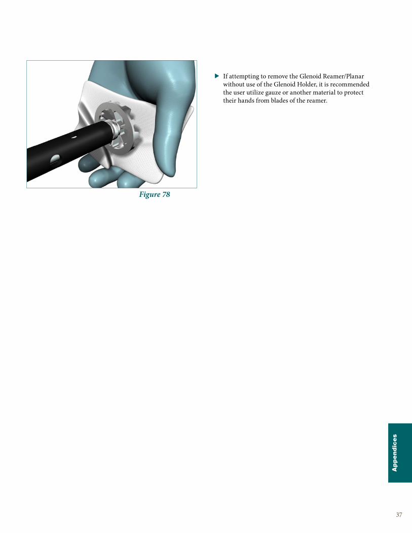
Figure 78
> If attempting to remove the Glenoid Reamer/Planar without use of the Glenoid Holder, it is recommended the user utilize gauze or another material to protect their hands from blades of the reamer.
37
Appendic
es
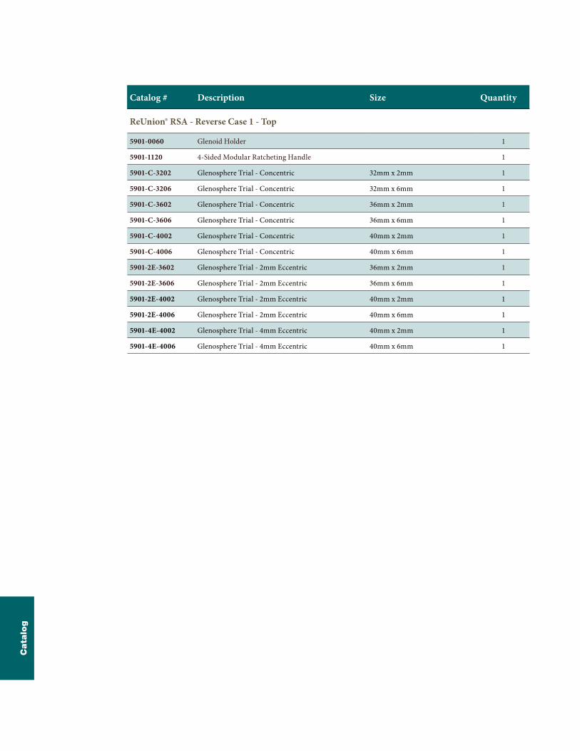
Catalog # Description Size Quantity
ReUnion® RSA - Reverse Case 1 - Top
5901-0060 Glenoid Holder 1
5901-1120 4-Sided Modular Ratcheting Handle 1
5901-C-3202 Glenosphere Trial - Concentric 32mm x 2mm 1
5901-C-3206 Glenosphere Trial - Concentric 32mm x 6mm 1
5901-C-3602 Glenosphere Trial - Concentric 36mm x 2mm 1
5901-C-3606 Glenosphere Trial - Concentric 36mm x 6mm 1
5901-C-4002 Glenosphere Trial - Concentric 40mm x 2mm 1
5901-C-4006 Glenosphere Trial - Concentric 40mm x 6mm 1
5901-2E-3602 Glenosphere Trial - 2mm Eccentric 36mm x 2mm 1
5901-2E-3606 Glenosphere Trial - 2mm Eccentric 36mm x 6mm 1
5901-2E-4002 Glenosphere Trial - 2mm Eccentric 40mm x 2mm 1
5901-2E-4006 Glenosphere Trial - 2mm Eccentric 40mm x 6mm 1
5901-4E-4002 Glenosphere Trial - 4mm Eccentric 40mm x 2mm 1
5901-4E-4006 Glenosphere Trial - 4mm Eccentric 40mm x 6mm 1
Cata
log

Catalog # Description Size Quantity
ReUnion® RSA - Reverse Case 1 - Bottom
5901-1100 Baseplate Centering Guide - Right 1
5901-1101 Baseplate Centering Guide - Left 1
5901-1106 Superior Humeral Resection Guide 1
5901-1113 Glenoid Reamer/Planar 32mm 1
5901-1114 Glenoid Reamer/Planar 36mm 1
5901-1115 Glenoid Reamer/Planar 40mm 1
5901-1116 Baseplate Holder 1
5901-1117 Peripheral Drill Guide - Straight 1
5901-1118 Glenoid Planar 48mm 1
5901-1122 Center Screw T25 Driver 2
5901-1123 Peripheral Drill Guide - Angled 1
5901-1128 Peripheral Screw T25 Driver 2
5901-1194 Cannulated Straight Reamer Driver 1
5901-1195 Depth Gauge 1
Cata
log
ReUnion RSA Reverse Shoulder Surgical Protocol
Catalog # Description Size Quantity
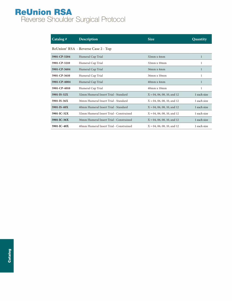
ReUnion® RSA - Reverse Case 2 - Top
5901-CP-3204 Humeral Cup Trial 32mm x 4mm 1
5901-CP-3210 Humeral Cup Trial 32mm x 10mm 1
5901-CP-3604 Humeral Cup Trial 36mm x 4mm 1
5901-CP-3610 Humeral Cup Trial 36mm x 10mm 1
5901-CP-4004 Humeral Cup Trial 40mm x 4mm 1
5901-CP-4010 Humeral Cup Trial 40mm x 10mm 1
5901-IS-32X 32mm Humeral Insert Trial - Standard X = 04, 06, 08, 10, and 12 1 each size
5901-IS-36X 36mm Humeral Insert Trial - Standard X = 04, 06, 08, 10, and 12 1 each size
5901-IS-40X 40mm Humeral Insert Trial - Standard X = 04, 06, 08, 10, and 12 1 each size
5901-IC-32X 32mm Humeral Insert Trial - Constrained X = 04, 06, 08, 10, and 12 1 each size
5901-IC-36X 36mm Humeral Insert Trial - Constrained X = 04, 06, 08, 10, and 12 1 each size
5901-IC-40X 40mm Humeral Insert Trial - Constrained X = 04, 06, 08, 10, and 12 1 each size
Cata
log

Catalog # Description Size Quantity
ReUnion® RSA - Reverse Case 2 - Bottom
5901-1168 Glenosphere Holder/Impactor 1
5901-1169 Glenosphere Impactor Tip 2
5901-1170 Universal Impactor Adapter 1
5901-1171 Universal Impactor Tip 1
5901-1175 Humeral Assembly Block 1
5901-1184 Glenosphere Jackscrew 1
5901-1186 Forked Removal Tool 1
2112-0010 Polyethylene Removal Tool 1
5901-1196 Humeral Insert Impactor Tip 32mm 1
5901-1197 Humeral Insert Impactor Tip 36mm 1
5901-1198 Humeral Insert Impactor Tip 40mm 1
5901-CP-32EX Expanding Humeral Cup Trial 32mm 1
5901-CP-36EX Expanding Humeral Cup Trial 36mm 1
5901-CP-40EX Expanding Humeral Cup Trial 40mm 1
5901-SM-32IS Expanding Insert Trial - Standard 32mm - SMALL 1
5901-SM-32IC Expanding Insert Trial - Constrained 32mm - SMALL 1
5901-SM-36IS Expanding Insert Trial - Standard 36mm - SMALL 1
5901-SM-36IC Expanding Insert Trial - Constrained 36mm - SMALL 1
5901-SM-40IS Expanding Insert Trial - Standard 40mm - SMALL 1
5901-SM-40IC Expanding Insert Trial - Constrained 40mm - SMALL 1
5901-LG-32IS Expanding Insert Trial - Standard 32mm - LARGE 1
5901-LG-32IC Expanding Insert Trial - Constrained 32mm - LARGE 1
5901-LG-36IS Expanding Insert Trial - Standard 36mm - LARGE 1
5901-LG-36IC Expanding Insert Trial - Constrained 36mm - LARGE 1
5901-LG-40IS Expanding Insert Trial - Standard 40mm - LARGE 1
5901-LG-40IC Expanding Insert Trial - Constrained 40mm - LARGE 1
Cata
log
Catalog # Description Size
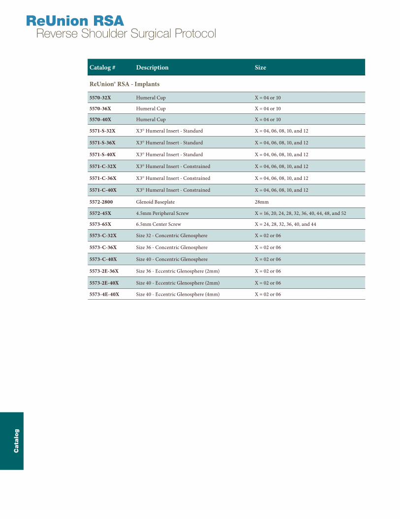
ReUnion® RSA - Implants
5570-32X Humeral Cup X = 04 or 10
5570-36X Humeral Cup X = 04 or 10
5570-40X Humeral Cup X = 04 or 10
5571-S-32X X3© Humeral Insert - Standard X = 04, 06, 08, 10, and 12
5571-S-36X X3© Humeral Insert - Standard X = 04, 06, 08, 10, and 12
5571-S-40X X3© Humeral Insert - Standard X = 04, 06, 08, 10, and 12
5571-C-32X X3© Humeral Insert - Constrained X = 04, 06, 08, 10, and 12
5571-C-36X X3© Humeral Insert - Constrained X = 04, 06, 08, 10, and 12
5571-C-40X X3© Humeral Insert - Constrained X = 04, 06, 08, 10, and 12
5572-2800 Glenoid Baseplate 28mm
5572-45X 4.5mm Peripheral Screw X = 16, 20, 24, 28, 32, 36, 40, 44, 48, and 52
5573-65X 6.5mm Center Screw X = 24, 28, 32, 36, 40, and 44
5573-C-32X Size 32 - Concentric Glenosphere X = 02 or 06
5573-C-36X Size 36 - Concentric Glenosphere X = 02 or 06
5573-C-40X Size 40 - Concentric Glenosphere X = 02 or 06
5573-2E-36X Size 36 - Eccentric Glenosphere (2mm) X = 02 or 06
5573-2E-40X Size 40 - Eccentric Glenosphere (2mm) X = 02 or 06
5573-4E-40X Size 40 - Eccentric Glenosphere (4mm) X = 02 or 06
ReUnion RSA Reverse Shoulder Surgical Protocol
Cata
log

Notes

Notes
ReUnion RSA Reverse Shoulder Surgical Protocol

Notes

Notes
ReUnion RSA Reverse Shoulder Surgical Protocol

Notes
325 Corporate DriveMahwah, NJ 07430t: 201 831 5000
www.stryker.com
A surgeon must always rely on his or her own professional clinical judgment when deciding whether to use a particular product when treating a particular patient. Stryker does not dispense medical advice and recommends that surgeons be trained in the use of any particular product before using it in surgery.
The information presented is intended to demonstrate the breadth of Stryker product offerings. A surgeon must always refer to the package insert, product label and/or instructions for use before using any Stryker product. Products may not be available in all markets because product availability is subject to the regulatory and/or medical practices in individual markets. Please contact your Stryker representative if you have questions about the availability of Stryker products in your area.
Stryker Corporation or its divisions or other corporate affiliated entities own, use or have applied for the following trademarks or service marks: ReUnion, Stryker, X3. All other trademarks are trademarks of their respective owners or holders.
REUNI-SP-1 5/14 Copyright ©2014 Stryker Printed in USA