Embed Size (px)
Citation preview

Results of the GNSS Receiver Experiment OCAM-G on Ariane-5 flight VA 219
André Hauschild*, Markus Markgraf*, Oliver Montenbruck*, Horst Pfeuffer**, Elie Dawidowicz***, Badr Rmili****, Alain Conde Reis*****
* German Aerospace Center (DLR), Oberpfaffenhofen, Germany
** OHB System AG, Munich, Germany
*** Thales Alenia Space Belgium (ETCA), Charleroi, Belgium
**** French Space Agency (CNES), Paris, France
***** European Space Agency (ESA), Paris, France
Abstract
The fifth Automated Transfer Vehicle (ATV) was launched on July 29, 2014 with Ariane-5 flight VA
219 into orbit from Kourou, French Guiana. For the first time, the ascent of an Ariane rocket was
independently tracked with a Global Navigation Satellite System (GNSS) receiver on this flight. The
GNSS receiver experiment OCAM-G was mounted on the upper stage of the rocket. Its receivers
tracked the trajectory of the Ariane-5 from lift-off until after the separation of the ATV. This paper
introduces the design of the experiment and presents an analysis of the data gathered during the flight
with respect to the GNSS tracking status, availability of navigation solution and navigation accuracy.
Keywords: GNSS, Ariane-5, ATV-5, OCAM-G, Launcher Trajectory Estimation
1. Introduction
On July 29, 2014 the Ariane-5 flight VA 219 lifted the fifth and last Automated Transfer Vehicle (ATV) “Georges
Lemaître” into space. This mission also marks the first time that GNSS receivers were flown onboard the Ariane-5
launcher and tracked the trajectory of the upper stage from lift-off at the space center in Kourou, French Guiana,
until after the ATV separation over the Pacific Ocean. The GNSS receivers are part of the OCAM-G instrument,
which was mounted in the vehicle equipment bay (VEB) directly below the payload section of the rocket. In addition
to the GNSS receivers, two video cameras were installed under the fairing which protects the payload during ascend.
These cameras provided video footage of the fairing separation and the release of the ATV into its target orbit.

2
The Online Camera System (OCAM) has originally been designed by OHB System AG (formerly Kayser-Threde
GmbH) to monitor booster, third stage and payload separation and has first been flown on an Ariane-5 in October
2006. Further developments of the unit were directed towards making it completely autonomous from the launch
vehicle. The second generation of the OCAM instrument has integrated batteries for independent power supply,
storage and processing capacities for the collected data, and a transmitting unit including antennas. These features
allow the OCAM unit to be operated without the need for any resources from the launch vehicle. The data
transmission is also separated from the launcher’s telemetry and received through independent ground stations. The
OCAM instrument is therefore suitable for use on various rockets and has been launched in several missions with
Ariane-5 and Soyouz [1]. For the experiment on the Ariane-5 ATV5 launch, the GNSS-capable version of the
instrument OCAM-G has an additional FPGA board to handle the data stream from the three satellite navigation
receivers. The receivers’ raw data as well as the video frames of the cameras are transmitted through one telemetry
stream, which has been received by tracking stations in Kourou, French-Guyana, and Weilheim, Germany, during the
mission.
The paper begins with a description of the OCAM-G unit and provides an overview of the events during the Ariane-5
flight during the operation of the experiment. Then the receiver tracking performance is analyzed with respect to the
number of tracked satellites and the availability of the real-time navigation solution. The analysis continues with a
characterization of the GNSS antenna coupling system and an investigation of possible multipath effects.
2. OCAM-G instrument design
A block diagram of the OCAM-G electronic unit (OEU) is depicted in Figure 1. The top part of the figure shows the
OCAM control and power management housekeeping unit (OCPM). It is responsible for the power dissemination in
the unit and allows interaction with different components, for example the activation or deactivation of low-noise-
amplifiers (LNAs) and the switching between different serial interfaces to the GNSS receivers. For this purpose, a
timeline of commands is stored in the housekeeping unit and executed during the mission. The OCPM also offers
overcurrent detection for single event latch-up effects and temperature sensors for each GNSS receiver board. The
OCAM Video Compression - TM/TC Board (VCTM) receives the video data from the cameras and converts it into
compressed format. It also receives the data streams from the GNSS receivers, which are merged with the
compressed video data into telemetry frames. These frames are stored in memory for later transmission during a

3
ground station contact. In addition the data can also be transmitted directly in real-time. Two dedicated OCAM-G
telemetry antennas are mounted on the exterior structure of the vehicle equipment bay for this purpose.
Figure 1: Block diagram of the OCAM-G experiment unit
The OCAM GNSS Interface board (OGIF) houses two AsteRx-m GNSS receivers from Septentrio N.V., Belgium,
and one Phoenix-S GPS receiver from DLR, Germany. The AsteRx-m is a commercial off-the-shelf receiver, which
is capable of GPS, GLONASS, Galileo, BeiDou, QZSS, and SBAS tracking [2]. The units used for OCAM-G
offered single-frequency tracking on 29 channels and were equipped with a special firmware without velocity- and
height-restrictions. The units were configured to track GPS, GLONASS and Galileo. The Phoenix-S receiver is a 12
channel single-frequency GPS receiver, which has been specifically developed for high-dynamics and space
applications [3][4]. An FPGA board serves as communication interface between the receivers and the OCPM and the
VCTM. The receivers are connected via an antenna coupler to the LNAs and the patch antennas. The coupling matrix
provides signals with similar gain from both antennas to the Phoenix-S receiver and one of the AsteRx-m receivers.
However, the second AsteRx-m unit receives signals from only one antenna with high gain. The other antenna
provides signals with a high attenuation. A characterization of the antenna coupler is provided in the analysis section
of this paper.
The two patch antennas were mounted on access doors on opposite sides of the launcher at a distance of
approximately 5.4 m, which corresponds to the diameter of the vehicle equipment bay. The antenna is suitable for
GNSS signal reception in the L1 band at 1575.42 MHz and has been specially designed for use on Ariane-5. The

4
location on the outside of the launcher’s hull, requires the antennas to withstand the aerodynamic stress and thermal
heat during ascend through the atmosphere. The LNAs are located on the inside of the access door below the GNSS
antenna. Figure 2 shows a picture of rocket’s vehicle equipment bay with one of the two OCAM-G GNSS antennas.
As already mentioned, the power of the LNAs can be switched off by the OCPM, thus cutting the receivers off from
GNSS signal reception. This has been done on purpose twice towards the end of the mission to test the receivers’ re-
acquisition after short signal interruptions.
Through the simultaneous reception of signals from both antennas, the receivers can receive GNSS signals from
almost any direction, which increases the GNSS satellite visibility significantly compared to a hemispherical pattern
of a single antenna. As a result, the receivers do not loose lock on tracked GNSS satellites even if the launcher
changes its attitude during flight. This is an important feature, since the Ariane-5 upper stage is kept in a slow roll
motion during most of the un-propelled flight phase to ensure equal heat distribution in the payload. The
disadvantage is that a signal from the same satellite may reach the receivers through both antennas concurrently and
thus cause multipath tracking errors.
Figure 2: Mounting position of one OCAM-G antenna on the Ariane-5 vehicle equipment bay marked by a red circle. The second antenna is mounted diametrically opposite (Photo: ESA–S. Corvaja)
3. Mission profile of Ariane-5 flight VA 219
The OCAM-G experiment was already activated prior to lift-off to collect GNSS measurements while the rocket was
still stationary on the launch pad. The activation occurred at approximately at 23:37:55 GPS time (GPST), about 10
minutes before ignition of the main engine. The main stage ignition happened at 23:47:54 GPST. This point in time
is also referred to as H0. The rocket left the launch pad 7 seconds later, when the two solid rocket boosters (SRBs)

5
were ignited as well. Within the first 5 minutes of flight, the SRBs were separated from the main stage and the
fairing was removed from the upper stage. The first 17 minutes of the mission have been propelled ascend, which
was only briefly interrupted by to the separation of the main stage from the upper stage. From 00:05:04 GPST to
00:47:23 GPST, the upper stage continued its trajectory in free-flight until the injection into the final orbit with a
short firing of the upper stage engine. The ATV5 separation happened at 00:51:49 GPST over New Zealand. The
OCAM-G experiment was then deactivated 8 minutes after the ATV separation and has tracked the flight trajectory
of the Ariane-5 for approximately 72 minutes until then. Prior to deactivation, two reacquisition tests have been
performed during which the power to the LNAs has been cut off for two seconds. Important events of the mission are
summarized in Table 1. The epochs of the events are provided in GPS-time and in seconds relative to H0. The plots
in Figure 3 show the ground track and the height profile over time for the Ariane-5 of the ATV. The different colors
of the trajectory indicate the propelled and un-propelled segments of the flight. The final orbit at ATV separation was
a circular orbit with approximately 256 km altitude and 56° inclination [5].
Figure 3: Ground track (left plot) and height profile (right plot) of Ariane-5 VA 219
Table 1: Important events during the Ariane-5 VA219 in GPS-time and relative to H0 [5]
Event ∆t [sec] GPS time OCAM-G experiment activation -599 23:37:55 H0 (2014/07/29 23:47:38 UTC) 0 23:47:54 Lift-Off (and booster ignition) 7 23:48:01 Booster separation 141 23:50:15 Fairing separation 212 23:51:26 Main engine shutdown 529 23:56:43 Main stage separation 535 23.56:49 1. ignition of upper stage 542 23:56:56 Shutdown of upper stage 1032 00:05:04 2. ignition of upper stage 3569 00:47:23 Shutdown of upper stage 3598 00:47:51 ATV5 separation 3835 00:51:49 1. LNA powercycle test (off for 2 sec) 3878 00:52:32 2. LNA powercycle test (off for 2 sec) 3998 00:54:30 OCAM-G experiment deactivation 4322 00:59:56
-180 -150 -120 -90 -60 -30 0 30 60 90 120 150 180Longitude
-90-75-60-45-30-15
0153045607590
Latit
ude
free flightpropelled flight 2014/07/29
50m30.
10m 20m 30m 40m 50m
GPS Time
0
50
100
150
200
250
300
Hei
ght [
km]
free flightpropelled flight

6
4. GNSS satellite tracking status
The number of tracked satellites over time for the three different receivers is depicted in Figure 4, Figure 5, and
Figure 6. It becomes obvious that the three receivers have tracked a high number of satellites during the entire flight.
The Phoenix-S receiver only supports GPS and has tracked typically between 6 and 12 satellites as shown in Figure
4. Towards the end of the flight, the receiver loses all tracked satellites twice for a short period of time due to the
intentional LNA power cycles. The re-acquisition behavior of the receiver will be analyzed later in this section.
Figure 4: Number of tracked satellites for Phoenix-S receiver
The AsteRx-m receivers have tracked GPS, GLONASS and Galileo satellites as depicted in Figure 5 and Figure 6.
Similar to the Phoenix-S receiver, the AsteRx-m 1 reports measurements for typically between 8 and 12 GPS
satellites. The number of GLONASS satellites is only slightly lower and varies typically between 4 and 12. The
AsteRx-m receivers also tracked all three Galileo satellites, which were active during the mission. The AsteRx-m 1
receiver exhibits two additional distinct drops in the number of satellite shortly after launch. Interestingly, these
drops have not been very pronounced for the Phoenix-S receiver. Closer inspection reveals that they coincide with
the booster separation and fairing separation events.
The second AsteRx-m receiver exhibits a similar performance as the AsteRx-m 1 as shown in Figure 6, although a
direct comparison of the plots shows that a slightly lower number of tracked satellites on average. The reason for this
different tracking performance can be found in the antenna connection for this receiver. The Phoenix-S receiver and
the AsteRx-m 1 receiver are connected such, that they receive signals from both antennas with a similar gain. The
AsteRx-m 2, on the other hand, receives signals from antenna 1 only with high attenuation, which causes the receiver
to acquire and track fewer satellites. The antenna coupling to the receivers will be analyzed in further detail in a later
section. The four drops in the number of satellites are also clearly visible for this receiver.

7
Figure 5: Number of tracked satellites for AsteRx-m receiver 1
Figure 6: Number of tracked satellites for AsteRx-m receiver 2
The four distinct events, where the receivers lost all or a significant part of the tracked satellites, will now be
analyzed in further detail. It is of special interest how quickly the receivers can provide a navigation solution again
after a loss of all satellites. The first drop depicted in Figure 7 coincides with the booster separation. Note that the
gap from 23:50:20 GPST to 23:50:21 GPST is due to missing data. The AsteRx-m receivers lose lock on all 22
tracked satellites and take approximately 6 seconds to reacquire the same number of satellites again. Both AsteRx-m
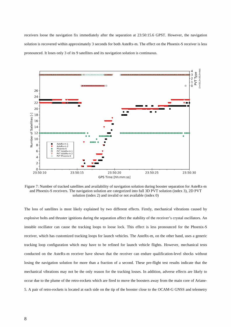
8
receivers loose the navigation fix immediately after the separation at 23:50:15.6 GPST. However, the navigation
solution is recovered within approximately 3 seconds for both AsteRx-m. The effect on the Phoenix-S receiver is less
pronounced. It loses only 3 of its 9 satellites and its navigation solution is continuous.
Figure 7: Number of tracked satellites and availability of navigation solution during booster separation for AsteRx-m and Phoenix-S receivers. The navigation solution are categorized into full 3D PVT solution (index 3), 2D PVT
solution (index 2) and invalid or not available (index 0)
The loss of satellites is most likely explained by two different effects. Firstly, mechanical vibrations caused by
explosive bolts and thruster ignitions during the separation affect the stability of the receiver’s crystal oscillators. An
instable oscillator can cause the tracking loops to loose lock. This effect is less pronounced for the Phoenix-S
receiver, which has customized tracking loops for launch vehicles. The AsteRx-m, on the other hand, uses a generic
tracking loop configuration which may have to be refined for launch vehicle flights. However, mechanical tests
conducted on the AsteRx-m receiver have shown that the receiver can endure qualification-level shocks without
losing the navigation solution for more than a fraction of a second. These pre-flight test results indicate that the
mechanical vibrations may not be the only reason for the tracking losses. In addition, adverse effects are likely to
occur due to the plume of the retro-rockets which are fired to move the boosters away from the main core of Ariane-
5. A pair of retro-rockets is located at each side on the tip of the booster close to the OCAM-G GNSS and telemetry
9
antennas. The plume of these rockets contains metal oxide that can mask or reflect RF signals. This effect seems to
manifests itself in an increase of errors in the OCAM-G telemetry data during booster separation due to a degradation
of the data link. It is likely that the signals of the telemetry antennas are reflected on the separation thrusters’ plume,
which temporarily causes a weak RF link to the ground station. Similarly, the plume may block the signals of some
satellites from reaching the GNSS antennas. Another possible explanation is that the reflected telemetry signal
interferes with the GNSS signals. This assumption is supported by an observed gain drop in the automatic gain
control (AGC) on both AsteRx-m receivers during the booster separation. An AGC gain drop as a result of a power
surge in the GNSS band leads to weaker signal levels at the receivers’ front end, which thus may be responsible for
loss of tracking. Hence, in addition to the tracking loop instability, there may also be an effect related to the tracking
loop sensitivity. However, based on the current data, no final conclusion can be made about the effect of the retro-
rocket plume on the GNSS signals.
The second drop in the number of satellites coincides with the fairing separation and is depicted in Figure 8. The data
gaps visible at the beginning of the plot and at 23:51:38 GPST are again due to missing data. Similar to the booster
separation, the launcher is subject to high mechanical shock loads due to the explosive bolts separating the two
fairing parts. In addition to the shock loads, the two detached fairing parts potentially mask a portion of the antenna
field of view when flying past the rocket’s upper stage, which may also contribute to the loss of GNSS signals. For
the two AsteRx-m receivers, the satellite visibility drops from 23 to 10 and 4, respectively. The Phoenix-S receiver
loses 5 of its 12 tracked satellites. It takes approximately 8 seconds for the AsteRx-m receivers and about 4 seconds
for the Phoenix-S receiver to acquire again the same number of satellites as prior to the fairing separation.
Two differences are obvious between the two events: Firstly, in case of the booster separation, the AsteRx-m
receivers lose all tracked satellites almost instantly. In case of the fairing separation, the loss of satellites appears to
happen more slowly. Secondly, in case of the booster separation the number of tracked satellites drops down to zero
for both AsteRx-m receivers. In case of the fairing separation, however, the AsteRx-m 2 receiver still maintains lock
on a higher number of satellites compared to the AsteRx-m 1.
As a result of the different number of tracked satellites, the availability of the navigation solution is also different for
the AsteRx-m receivers in this case. The AsteRx-m 1 does not provides a continuous navigation solution for a time
intervals of about 3.5 seconds, which is interrupted by isolated periods of time with short availability of 3D or 2D
navigation fixes. The AsteRx-m 2 requires approximately one second until it provides a PVT solution again.
However, two isolated epochs without valid navigation solution occur approximately 3 and 5 seconds after the
separation. The Phoenix-S receiver provides PVT data without interruption during the entire time.

10
Figure 8: Number of tracked satellites and availability of navigation solution during fairing separation for AsteRx-m and Phoenix-S receivers. The navigation solutions are categorized into full 3D PVT solution (index 3), 2D PVT
solution (index 2) and invalid or unavailable solution (index 0)
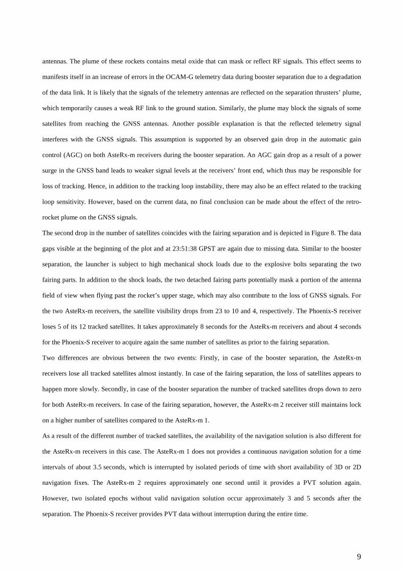
Another pair of outages happens towards the end of the experiment after the ATV-5 separation. These are related to
two LNA powercycle tests, during which the power to both LNAs has been cut off simultaneously for 2 seconds. The
number of tracked satellites and the availability of the navigation solution for all three receivers are depicted in
Figure 9 and Figure 10. Unfortunately, the receivers’ data from 00:52:32.0 GPST to 00:52:33.9 GPST and from
00:52:32.0 GPST to 00:52:32.9 GPST has been lost due to transmission problems. The first data gap hinders the
exact identification of the start time of the first LNA test.
The first LNA test was planned for 00:52:32.0 GPST. The Phoenix-S receiver still provides a single valid navigation
solution after the data gap, when the other receivers have already lost the PVT fix. When the number of tracked
satellites drops to 3, the navigation solution from the Phoenix-S becomes unavailable for one second and is regained
again at 00:52:35.0 GPST. It is interesting to note that the receiver apparently still maintains track on a few satellites,
even with the LNA power disabled. The AsteRx-m 1 and AsteRx-m 2 receivers do not provide a full 3D PVT
solution for 4 seconds and 6 seconds, respectively. The second LNA test was planned for 00:54:30 GPST. Similar to
the previous test, the Phoenix-S receiver still provides a navigation solution, when the AsteRx-m receivers are
11
already reporting invalid solutions. When the receiver loses track on the satellites, the Phoenix-S receiver does not
report a navigation solution for about 1.5 s, until a fix is regained at 00:54:35.4 GPST. Similar to the previous test,
the AsteRx-m receivers do not provide PVT solutions for a longer time interval, again approximately 4 s for the
AsteRx-m 1 and 6 s for the AsteRx-m 2.
The analysis of the number of satellites has revealed that the different receiver types react differently to the booster
and fairing separation events. Further testing of the receivers’ crystal oscillators or the use of an inertial measurement
unit in a hybrid navigation system deems necessary to check, if a loss of the navigation solutions can be avoided in
this critical phase of the flight.
Figure 9: Number of tracked satellites and availability of navigation solution during first LNA test for AsteRx-m and Phoenix-S receivers. The navigation solutions are categorized into full 3D PVT solution (index 3), 2D PVT solution
(index 2) and invalid or unavailable solution (index 0)

12
Figure 10: Number of tracked satellites and availability of navigation solution during second LNA test for AsteRx-m and Phoenix-S receivers. The navigation solutions are categorized into full 3D PVT solution (index 3), 2D PVT
solution (index 2) and invalid or unavailable solution (index 0)
5. Receiver navigation solutions
Prior to the analysis and discussion of the navigation accuracy, the effect of the dual-antenna system shall be
discussed briefly. Through the coupling matrix, the receivers are supplied with signals from both antennas on
opposite sides of the launcher. This design increases the field of view for GNSS signal reception, which facilitates
tracking a high number of satellites simultaneously, but the receivers cannot distinguish from which antenna the
measurements originate. Therefore, the receivers’ internal navigation solutions are computed as if all measurements
are made at one antenna. This introduces position errors on the order of the launcher diameter, however, for
applications like real-time trajectory estimation and range safety these errors are acceptable and the advantage of
increased satellite visibility through the multi-antenna system prevails. Robust mitigation of this effect would require
real-time information about the launcher’s attitude provided to dedicated receivers, which support separate input
from multiple antennas and compute one combined navigation solution. The lack of attitude information does also
not allow correcting for the lever arm of the two antennas in post-processing. Even with this information at hand, it
may not always be straightforward to decide through which antenna a satellite has been tracked, and situations may

13
occur, where signals of one satellite are received through both antennas simultaneously. Therefore, the effect of the
antenna baseline has neither been corrected for in the receivers’ navigation solutions nor in the post-processed
solutions.
In absence of precise information about the true trajectory and attitude of the vehicle, the receivers’ navigation
solution accuracy cannot be determined directly. Instead, the consistency of the navigation solutions has been
assessed by direct comparisons of the position and velocity solutions of the different receivers. Table 2 summarizes
the results for the root-mean-square (rms) differences for position and velocity differences between the two AsteRx-
m receivers and the AsteRx-m 1 and the Phoenix-S receivers starting at 7 minutes after lift-off until shortly before
the ATV5 separation. The two AsteRx-m position solutions are consistent with an rms of less than 1 m in East and
North direction and approximately 2 m in vertical direction. The rms of the velocity differences are about 0.3 m/s in
both horizontal directions and 1.1 m/s in vertical direction. The comparison between the AsteRx-m 1 and the
Phoenix-S shows larger inconsistencies in the corresponding navigation solutions. The horizontal rms position
difference amounts to approximately 2 m in East and North and about 5 m vertically. These larger differences
between the two navigation solutions are due to the chosen configuration of the Phoenix-S receiver. This unit has
been configured for maximum availability the navigation solution at the expense of the highest possible accuracy.
The main reason for the reduced accuracy is that newly acquired satellites haven been included in the navigation
solution as quickly as possible rather than waiting until the tracking loop has been stabilized. The degradation is also
notable in the differential velocity, which has rms differences of about 1 m/s in East, 1.4 m/s in North, and 3.1 m/s in
up direction.
Table 2: Position and velocity differences between receiver navigation solutions
Receivers rms position differences [m] rms velocity differences [m/s] East North Up 3D East North Up 3D
AsteRx-m 1 / AsteRx-m 2 0.85 0.93 2.11 2.46 0.33 0.37 1.10 1.20 AsteRx-m 1 / Phoenix-S 1.93 2.35 4.97 5.83 1.04 1.42 3.10 3.57
As a complementary analysis, the receiver navigation solution is also compared to a smoothed trajectory. This
smoothed trajectory has been computed from a Least-Squares fit of a position and velocity state vector using a
reduced-dynamics orbital model to the epoch-by-epoch position solutions of the receiver. Figure 11 depicts a
comparison of the AsteRx-m 1 receiver navigation solution with respect to this fitted trajectory for a time interval of
25 minutes when the rocket is in free-flight mode. Though the differences in the East, North, and up direction

14
depicted in the plot do again not reflect the absolute position errors, at least an approximate assessment of the
precision can be made. The navigation solution and the fitted trajectory exhibit differences on the order of a few
meters. An oscillation of the position differences is visible especially in the up-component. This effect is due to the
relative motion of the antennas’ positions with respect to the fitted trajectory. This relative motion is caused by
attitude changes of the rocket in free-flight, in this case a roll-motion to ensure equal heat distribution on the payload.
Figure 11: Comparison of AsteRx-m 1 navigation solution with smoothed trajectory
Finally, the navigation solutions during the first few minutes of the flight with the booster and fairing separation are
analyzed. For this analysis, a post-processed trajectory based on Phoenix-S measurements has been used as a
reference, since it provides continuous observations even during the two separation events. The navigation solutions
of the two AsteRx-m receivers are compared to this reference in Figure 12 and Figure 13. During the fairing
separation significant differences on the order of several tens of meters can be observed, which are especially
pronounced in the up direction. For the remaining time, the navigation solutions typically agree to the post-processed
Phoenix-S trajectory within less than 10 meters. It should be noted again though, that the analysis provided here may
not be regarded as an assessment of the absolute positioning accuracy of the receivers, since only comparative
assessments are possible without additional external reference data. This holds true especially for the assessment

15
during the fairing separation, since the trajectory of the Phoenix-S receiver selected as a reference is most likely
subject to a reduced accuracy as well during the separation events.
Figure 12: Comparison of AsteRx-m 1 navigation solution with post-processed Phoenix-S trajectory during booster and fairing separation events
Figure 13: Comparison of AsteRx-m 2 navigation solution with post-processed Phoenix-S trajectory during booster and fairing separation events. Note the different scale of the up component’s y-axis

16
6. Characterization of antenna coupling system
The antenna coupling system used to connect the three GNSS receivers to the two antennas does not provide equal
signal gain for each connection. The corresponding gains have been determined by pre-flight calibrations and are
provided in Table 3. The Phoenix-S and AsteRx-m 1 receiver have similar values for both antennas. The AsteRx-m 2
receiver, however, has a significantly larger attenuation for antenna 1 compared to the other receivers.
Table 3: Signal gain in OCAM-G antenna coupling matrix
Receiver LNA/Ant 1 LNA/Ant 2 Phoenix-S -9 dB -9 dB AsteRx-m 1 -9 dB -11 dB AsteRx-m 2 -22 dB -6 dB AsteRx-m 1-2 +13 dB -5 dB
The plot in Figure 14 shows the observed C/N0 for the GPS satellite PRN G20 of the AsteRx-m receivers over a 20
minute time interval during the coasting phase between the first and second ignition of the upper stage. During this
phase of the flight, the launcher’s x-axis is oriented perpendicular to the sun vector and the vehicle is spinning
around this axis to ensure uniform heat distribution in the payload. As a result, GNSS satellites have an alternating
visibility from antenna 1 and 2 provided that their line-of-sight (LOS) vectors are not aligned with the vehicle spin
axis. The continuous tracking of PRN G20 by the AsteRx-m receiver 2 suggests that the coupling matrix does not
completely isolate this receiver from antenna 1. The plot shows a periodic decrease and increase in the observed
C/N0 for both receivers. In case of the AsteRx-m receiver 1, the peak values are about 47 dB-Hz and about 49 dB-
Hz. The difference of 2 dB-Hz between the two peak values corresponds perfectly with the gain difference between
antenna 1 and antenna 2 for this receiver listed in Table 3. For the AsteRx-m receiver 2, the maximum C/N0 values
are alternating between approximately 39 dB-Hz and 51 dB-Hz. The difference between these two values
corresponds well to the antenna gain difference expected from Table 3 for this receiver. The differences of C/N0
between the AsteRx-m 1 and AsteRx-m 2 in the plotted data are +10 dB-Hz and -4 dB-Hz at peak values. These
differences correspond reasonably well to the expected values listed in Table 3 and support the assumption, that the
AsteRx-m 2 receiver maintains track even if a satellite is only visible through antenna 1.

17
Figure 14: Observed C/N0 of AsteRx-m 1 (blue) and AsteRx-m 2 (red) for a selected GPS satellite
Very similar results for C/N0 over time have been observed for other GNSS satellites as well. Therefore statistics on
the C/N0 differences between the two AsteRx-m receivers allow further insight. The C/N0 difference between
receiver 1 and 2 has been computed for all commonly observed satellites as follows
2010120
−
=
∆
N
C
N
C
N
C (1)
where 10)/( NC and 20)/( NC are the observed carrier-to-noise density ratios at receiver 1 and 2, respectively,
and 120)/( NC∆ is the carrier-to-noise density ratio difference in dB-Hz. The results depicted in Figure 15. The top
plot shows the statistics for GPS satellites based on about 385000 data samples and the bottom plot depicts results for
GLONASS based on 271000 data samples. Galileo has been omitted in this analysis due to the low number of
available observations. Two peaks are clearly visible in the data: one peak at +10 dB-Hz for GPS and GLONASS
satellites and another peak at -4 dB-Hz for GPS and -5 dB-Hz for GLONASS. These values for the C/N0 differences
are in good agreement with the previous results.

18
Figure 15: Histogram of C/N0 differences between AsteRx-m 1 and AsteRx-m 2 based on 385000 samples for GPS (top plot) and 271000 samples for GLONASS (bottom plot)
7. Multipath effects
Coupling of two antipodal antennas to the same receivers significantly increases the satellites visibility, but a major
disadvantage of this configuration is the potential concurrent reception of signals from the same satellite. The
receiver will then track a superposition of the two signals, which have travelled along different transmission paths.
As a result, the pseudorange and carrier-phase observations will be affected by multipath errors compared to
observations from a signal that is received through only one antenna. Short-term oscillations of the measured C/N0
are usually a clear indication for the presence multipath signals. Depending on the relative phase-shift between the
two signals, their combination may be the result of constructive or destructive interference. In case of identical signal
amplitudes, constructive interference increases the C/N0 by up to +3 dB, whereas destructive interference reduces the
C/N0. The latter can lead to complete signal suppression, which causes the receiver to loose lock. GNSS satellite
motion and changes of the orientation between the receiving antenna and the GNSS satellite cause a variation of the
relative phase-shift of the two signals, which leads to an oscillation of the observed C/N0.
These effects can clearly be observed in the measurements of the GNSS receivers. Figure 16 shows plots for C/N0
and the pseudorange multipath errors for two selected satellites tracked by the AsteRx-m receiver 1. The rocket is in
the un-propelled flight phase with constant roll motion around the longitudinal axis at this time. The time interval
-20 -10 0 100
5
10
15
Differences of C/N0 (AsteRx-m #1-#2) [dB-Hz]
Freq
uenc
y [%
]
GLONASS
20
20
-20 -10 0 100
5
10
15
Freq
uenc
y [%
]
GPS
20
20

19
covers one complete rotation of the vehicle, which takes approximately 2.5 minutes. The top plot for GPS satellite
PRN G23 shows extended periods with strong C/N0 oscillations. The maximum difference in C/N0 is approximately
10 dB-Hz which suggests similar amplitudes between the two concurrently received signals. The satellite has an
elevation angle of approximately 45° with respect to the rocket’s local horizon. The bottom plot for G16 exhibits
significantly higher periodicity of the C/N0 variation, which is caused by a faster relative phase change of the two
signals. This satellite has an elevation angle of approximately 90° and is therefore almost directly in zenith direction.
As expected, the different satellites are affected differently by multipath variations depending on how the dual-
antenna system changes its orientation with respect to the satellite.
Figure 16: Multipath errors and C/N0 for two selected GPS satellites tracked by the AsteRx-m receiver 1
For an approximate assessment of the pseudorange tracking error caused by the signal interference, the difference
between pseudorange and carrier-phase measurements has also been plotted in Figure 16. This signals combination
removes all common terms like relative geometry between transmitting and receiving GNSS antenna and clock
offsets. It is still affected by signal biases and the carrier-phase ambiguities. The offset caused by these terms has
been removed from the data before plotting. Since the signal delay caused by the ionosphere affects the pseudorange
and carrier-phase with equal magnitude but opposite sign, the difference of the two observations also subject to twice
the magnitude of the change in ionospheric delay over the 2.5 minute time interval. The initial delay has also been
removed together with the bias and the ambiguity term. Assuming that noise and multipath of the carrier-phase can
20
be neglected compared to the pseudorange errors and that the variation of the ionospheric delay is low, the code-
carrier difference allows a coarse assessment of the multipath errors. Although the presence of multipath is likely as
indicated by the C/N0 oscillations, the plot reveals that the pseudorange does not exhibit increased errors which can
be clearly attributed to this effect. It appears that the employed receivers are not sensitive to the short delay multipath
caused by the antenna coupling system. This can mainly be attributed to the low bandwidth of the code tracking loop,
which effectively filters the code tracking error induced by the high-frequency multipath variation.
8. Summary, conclusions and future work
With the OCAM-G experiment, GNSS receivers have been flown onboard an Ariane-5 rocket for the first time. The
three receivers have successfully tracked the trajectory of the upper stage from lift-off until the end of the experiment
approximately 72 minutes later. The receivers have reported measurements for a high number of GNSS satellites
during most of the time, allowing the robust computation of a navigation solution. Satellite tracking is affected by the
shock loads and potential signal masking effects caused by booster and fairing separation, which caused a short
interruption of the PVT solution for two of the three receivers. A modification of the receivers’ crystal oscillators
may partly mitigate this problem. Further investigations may bring more insight into which effects are the dominant
cause for the loss of signal tracking and how they can best be avoided in a future mission. Assessment of the
receivers’ navigation solution suggests that the precision is typically on the order of a few meters. The receivers have
reported consistent navigation solutions, except for the phases with challenging tracking conditions during the
booster and fairing separation events. A coupled antenna system has been used for the experiment, which has
significantly increased the satellite visibility compared to a single hemispherical antenna. The coupling of the
antenna has led to multipath GNSS signal reception, however, adverse effects on the pseudorange measurements that
would have degraded the navigation solution could not be observed. The analysis of the OCAM-G measurements can
be further extended with external information about the launcher’s trajectory, attitude, and shock levels for this
flight.
A second flight qualified OCAM-G unit is available for a follow-up mission. A flight on a transfer orbit to a medium
Earth orbit promises new insight into the GNSS tracking and navigation capabilities beyond the terrestrial service
volume [6]. The limitations of GPS-only receivers in high-altitude orbits have already been demonstrated in the past
(see e.g. [7],[8]). The OCAM-G experiment however offers simultaneous GPS, GLONASS, and Galileo tracking in
the current configuration, which can easily be extended to also include BeiDou, SBAS, and QZSS. Using all these

21
systems together will increase the availability of satellites in higher altitudes and potentially also enable navigation
for most of the transfer orbit. Another interesting option is to include an inertial measurement unit (IMU) into the
OCAM-G unit. The IMU data can be used to fill potential gaps due to short outages in the real-time navigation of the
GNSS receivers and assess, through post-processing, the potential use of hybrid navigation for launch vehicles.
Acknowledgements
The authors wish to thank the ESA ATV Program and Ariane 5 operator Arianespace, for having offered this flight
opportunity for the OCAM-G unit free of charge. CNES is acknowledged for optimizing the system specification,
configuration, and complete mission support. Airbus Defence and Space is acknowledged for the provision of
telemetry and GNSS antennas, for performing all required implementation activities, and for the fruitful co-operation
during mission support. Thanks also go to Arianespace for the support in all integration and test phases. The PI group
is acknowledged for the definition and selection of the experiments. Septentrio is acknowledged for providing the
AsteRx-m GNSS receivers and support. The authors also thank the staff at the ground stations at Weilheim (DLR),
Perth (ESA) and Galliot (CNES) for the reception of the telemetry data.
References
[1] Conde Reis, A., Fricke, G., Pfeuffer, H., Soviche, A., Astier, V., Rmili, B. 2010. Onboard Video Telemetry for
European Launchers. In: SpaceOps 2010 Conference, Huntsville AB, April 25-30
[2] Septentrio Satellite Navigation. 2012. AsteRx-m Data Sheet. Available online at
http://www.septentrio.com/sites/default/files/AsteRx-m_DS_V082014_21.pdf, last accessed May 18, 2015
[3] Markgraf, M., Montenbruck, O. 2005. Phoenix-HD - A Miniature GPS Tracking System for Commercial and
Scientific Rocket Launches; 6th International Symposium on Launcher Technologies, Munich Germany,
November 8-11
[4] Montenbruck, O., Gill, E., Markgraf, M. 2006. Phoenix-XNS - A Miniature Real-Time Navigation System for
LEO Satellites. 3rd ESA Workshop on Satellite Navigation User Equipment Technologies NAVITEC' 2006,
Noordwijk, The Netherlands, December 11-13
[5] Arianespace. 2014. Ariane-5 Launch Kit. Available online at http://arianespace.com/images/launch-kits/launch-
kit-pdf-eng/VA219-launchkit-EN1.pdf, last accessed May 18, 2015

22
[6] Bauer, F.H., Moreau, M.C., Dahle-Melsaether, M.E., Petrofski, W.P., Stanton, B.J., Thomason, S., Harris, G.A.,
Sena, R.P., Parker Temple III, L. 2006. The GPS Space Service Volume. Proceedings of the 19th International
Technical Meeting of the Satellite Division of The Institute of Navigation (ION GNSS 2006), Fort Worth, TX,
September 26-29, pp. 2503-2514
[7] Moreau, M.C., Davis, E.P., Carpenter, J.R., Kelbel, D., Davis, G.W. and Axelrad, P. 2002. Results from the
GPS Flight Experiment on the High Earth Orbit AMSAT OSCAR-40 Spacecraft. Proceedings of the 15th
International Technical Meeting of the Satellite Division of The Institute of Navigation (ION GPS 2002),
Portland, OR, September 24-27, pp. 122-133
[8] Unwin, M.J., de Vos van Steenwijk, R., Hashida, Y., Kowaltschek, S., Nowak, L. 2014. GNSS at High
Altitudes – Results from the SGR-GEO on GIOVE-A. 9th International ESA Conference on Guidance,
Navigation & Control Systems (GNC2014), Porto, Portugal, June 2-6


![IAASS13 Arianespace 2013 [Mode de compatibilité]iaassconference2013.space-safety.org/wp-content/uploads/... · 2020. 7. 13. · 6 Ariane 2 11 Ariane 3 116 Ariane 4 68 Ariane 5 Arianespace](https://img.dokumen.tips/doc/110x75/60d4813d8eceea7d64273b8d/iaass13-arianespace-2013-mode-de-compatibilit-2020-7-13-6-ariane-2-11-ariane.jpg)