Embed Size (px)
Citation preview

RESOLUTION MSC.23(59) (adopted on 23 May 1991) ADOPTION OF THE INTERNATIONAL CODE FOR THE SAFE CARRIAGE OF GRAIN IN BULK

RESOLUTION HSC.23(S9)
(adopte& on 23 Hay 1991)
ADOPTION OF THE INTERNATIONAL CODE FOR THE SAFE CARRIAGE OF GRAIN IN BULK
THE MARITIME SAFETY COMMITTEE,
RECALLING Article 28(b) of the Convention on the International Maritime Organization concerning the functions of the Committee,
NOTING part C of revised chapter VI of the International Convention for the Safety of Life at Sea, 1974 (SOLAS 74), adopted by resolution HSC.22(S9) Which, inter alia, makes the provisions of the International Code for the Safe Carriage of Grain in Bulk mandatory under that Convention.
HAVING CONSIDERED the text of the proposed Code,
1. ADOPTS the International Code for the Safe Carriage of Grain in Bulk, the text of which is set out in the Annex to the present resolutionj
2. DECIDES that the Code shall t ake effe ct on 1 January 1994; Bnd
3. REQUESTS the Secretary-Genera1 to transmit to the Hembers of the Organization and all Contracting Governments to SOLAS 74 certified copies of the present resolution and the Code.
RESOLUTION MSC.23(59) (adopted on 23 May 1991) ADOPTION OF THE INTERNATIONAL CODE FOR THE SAFE CARRIAGE OF GRAIN IN BULK
RESOLUTION HSC.23(S9)
(adopte& on 23 May 1991)
ADOPTION OF THE INTERNATIONAL CODE FOR THE SAFE CARRIACE OF GRAIN IN BULK
THE MARITIME SAFETY COMMITTEE,
RECALLING Article 28(b) of the Convention on the International Maritime Organization concerning the funct ions of the Committee,
NOTING part C of revi sed chapter VI of the International Convention fo r the Safety of Life at Sea, 1974 (SOLAS 74), adopted by resolution MSC.22(S9) Which , inter alia , makes the provis ions of the International Code for the Safe Carriage of Grain in Bu lk mandatory under that Convention,
HAVING CONSIDERED the text of the proposed Code,
1. ADOPTS the International Code for the Safe Carrisge of Grain in Bulk . the text of which is set out i n the Annex to the present resolution;
2. DECIDES that the Code shall take effect on 1 January 1994; and
3. REQUESTS the Secretary-General to transmit to the Hembers of the Organization and all Contr a cting Government9 to SOLAS 74 certified copies of the present resolution and the Code.

- 2 -
ANNEX
PART A
SPECIFIC REQUIREMENTS
APPLICATION
1.1 This Code applies to ships regardless of size. including those of less than 500 tons gross tonnage, engaged in the carriage of grain in bulk, to which part C of chapter VI of the 197~ SOLAS Convention, as amended. applies.
1.2 For the purpose of this Code:
the expression "ships constructed" means "ships the keels of which are laid or which are at a similar stage of construction".
2 DEFINITIONS
2.1 The term "grain" covers wheat, maize (corn), oats, rye, barley. rice, pulses, seeds and proces sed forms thereof, whose behaviour is similar to that of grain in its natural state.
2.2 The teI'lD lIfilled compartment, trimmed", refers to any cargo space in wh ich, after loading and trimming as required under A 10.2, the bulk grain is At its highest possible level.
2.3 The term "filled compartment, untrimmed", re fe rs to a cargo s pace which is filled to the maximum extent pos sibl e in way of the hatch opening but whi ch has not been trimmed outside the periphery of the hatch opening either by the provisions of A 10.3.1 for all ships or A 10.3.2 for specially suit~ble compartments.
2.4 The term "partly filled compartment" refers to any cargo space wherein the bulk grain is not loaded in the manner prescribed in A 2.2 or A 2.3.
2.5 The term "angle of flooding" (al) means the angle of heel At which openings in the hull, superstructures or deckhouses, which cannot be closed weathe r tight, immerse. In applying this def inition, small openings through which progressive flooding cannot take place need not be considered 8S open.
2.6 The term "stowage factor", for the purposes of calculating the grain heeling moment caused by a shift of grain, mesns the volume per unit weight of the cargo as attested by the loading facility, i.e. no allowance shall be made for lost space wh en the cargo space is nominally filled.
2.7 The term "specially suitable compartment" refers to 8 cargo space wh ich is constructed with at least two vertical or sloping, longitudinal, gra in-t ight divisions wh ich are coincident with the hatch side girders or are so positioned as to limit the effect of any transverse shift of grain. If s l oping, the divisions ahall have an inclination of not les s than 30· to the horizontal.
RESOLUTION MSC.23(59) (adopted on 23 May 1991) ADOPTION OF THE INTERNATIONAL CODE FOR THE SAFE CARRIAGE OF GRAIN IN BULK
- 2 -
ANNEX
PART A
SPECIFIC REQUIREMENTS
APPLICATION
1.1 This Code applies to ships regardless of 8i~e. including those of less than 500 tons gross tonnage, engaged in the carriage of grain in bulk, to which part C of chapter VI of the 1974 SOLAS Convention, 85 amended, applies.
1.2 For the purpose of this Code~
the expression "ships constructed" means "ships the keels of which aTe laid or which are at a similar stage of construction".
2 DEFINITIONS
2.1 The term "grain" covers wheat, maize (corn), oats, rye, barley, rice. pulses, seeds and procesaed forms thereof, whos e behaviour is similar to that of grain in ita natural state.
2.2 The tetlD "filled compartment, trimmed", refers to any cargo space in whi ch, after loading and trimming as required under A 10.2, the bulk grain is at its highest possible level.
2.3 The tenn "filled compartment, untrimmed", re fers to a cargo space which is filled to the maximum extent possib le in way of the hatch opening but whi ch has not been tr i mmed outside the periphery of the hatch opening either by the provilions of A 10.3.1 for all ships or A 10.3.2 for specia lly suit~ble compartments.
2.4 The term. "partly filled compartment" refers to any cargo space wherein the bulk grain is not loaded in the manner prescribed in A 2.2 or A 2.3.
2.5 The term "angle of flooding" (91) means the angle of heel at which openings in the hull. superstructures or deckhouses, whi ch cannot be closed wea thertight, i mmerse. In applying thi s definit ion . small openings through wh ich progressive flooding cannot take plsce need not be considered ss open.
2.6 The t.erm "stovage factor", for the purposes of calculating the grain heeling moment caused by a shift of grain, means the volume per unit weight of the cargo as attested by the loading facility, i.e. no aLlowance ahall be made for lost space when the cargo space is nominally filled.
2.7 The term "specisll y suitable compartment" refers to a cargo space which is constructed with st least two vertical or sloping, longitudinal, grain-tight divisions wh ich are coincident with the hatch side girders or are so positioned as to limit the effect of any transverse shift of grain. If sloping, the divisions shall have an inclination of not less than 30 · to t he horizontal.

- 3 -
3 DOCUMENT OF AUTHORIZATION
3.1 A document of authorization ahall be issued for every ship loaded in accordance with the regulations of this Code either by the Administration or an organization recognized by it or by a Contracting Government on behalf of the Administration. It shall be accepted as evidence that the ship is capable of complying with the requirements of these regulations.
3. 2 The document shall accompany or be incorporated into the grain loading manual provided to enable the master to meet the requirements of A 7. The manual shall meet the requirements of A 6.3.
3.3 Such a document, grain loading stability data and associated plans may be drawn up in the official language or languages of the issuing country. If the language used is neither English nor French, the text shall include a translation into one of these languages.
3. 4 A copy of such a document, grain loading stability data and associated plans shall be placed on board in order that the master, if so required, shall produce them for the inspection of the Contracting Government of the country of the port of loading.
3.5 A ship without such a document of authorization shall not load grain until the master demonstrates to the satisfaction of the Administration, or of the Contracting Government of the port of loading acting on behalf of the Administration, that, in its loaded condition for the intended voyage, the ship complies with the requirements of this Code. See also A 8,3 and A 9.
4 EQUIVALENTS
Where an equivalent accepted by the Administration in accordance with regulation 1/5 of the International Convention for the Safety of Life at Sea, 1974, as amended, is used, particulars shall be included in the document of authorization or in the grain loading manual.
5 EXEMPTIONS FOR CERTAIN VOYAGES
The Administration, or a Contracting Government on behalf of the Administration, may, if it considers that the sheltered nature and conditions of the voyage ar e such as to render the application of any of the requirements of this Code unreasonable or unnecessary, exempt from those particular requirements individual ships or classes of ships.
6 INFORMATION REGARDING SHIP'S STABILITY AND GRAIN LOADING
6.1 Information in printed book let form shall be provided to enable the master to ensure that the ship complies with this Code when carrying grain in bulk on an international voyage. This information shall include that which is listed in A 6.2 and A 6. 3.
6.2 Information Which shall be acceptable to the Administration or to a Contracting Government on behalf of the Administration shall include:
.1 Ship's particul ars;
RESOLUTION MSC.23(59) (adopted on 23 May 1991) ADOPTION OF THE INTERNATIONAL CODE FOR THE SAFE CARRIAGE OF GRAIN IN BULK
- 3 -
3 DOCUMENT OF AUTHORIZATION
3.1 A document of authorization ahall be issued for every ship loaded in accordance with the regulations of this Code either by the Administration or an organization recognized by it or by a Contracting Government on behalf of the Administration. It shall be accepted as evidence that the ship is capable of complying with the requirements of these regulations .
3.2 The document shall accompany or be incorporated into the grain loading manual provided to enable the master to meet the requirements of A 7. The manual shall meet the requirements of A 6.3.
3.3 Such a document, grain loading stability data and associated plans may be drawn up in the official language or languages of the issuing country. If the language used is neither English nor French. the text ahall include a translation into one of these languages.
3. 4 A copy of such a document, grain loading stability data and associated plans shall be placed on board in order that the master, if 80 required, shall produce them for the inspection of the Contracting Government of the country of the port of loading.
3.5 A ship without such a document of authorization shall not load grain until the master demonstrates to the satisfaction of the Administration, or of the Contrac ting Government of the port of loading acting on behalf of the Administration, tha t . in its loaded condition for the intended voyage, the ship complies with the requirements of this Code. See also A 8,3 and A 9.
4 EQUIVALENTS
Where an equivalent accepted by the Administration in accordance with regulation 1/5 of the International Convention for the Safety of Life at Sea, 1974, as amended, is used, particulars shall be inc l uded in the document of authorization or in the grain loading manual.
5 EXEMPTIONS FOR CERTAIN VOYAGES
The Administration, or a Contracting Government on behalf of the Administration. may, if it considers that the sheltered nature and conditions of the voyage are such as to render the application of any of the requirements of this Code unreasonable or unnecessary, exempt from thoae particular requirements individual ships or classes of ships.
6 INFORMATION REGARDING SHIP'S STABILITY AND GRAIN LOADING
6.1 Information in printed book let form shall be provided to enable the master to ensure that the ship complies with this Code when carrying grain in bulk on an international voyage. This information shall include that which is listed in A 6.2 and A 6. 3.
6.2 Information which shall be acceptable to the Administration or to a Contracting Government on behalf of the Administration shall include:
.1 Ship's particulars;

- 4 -
.2 lightship di splac~ment and the vertical distance from the intersection of the moulded base line and midship section to the centre of gravity (KG);
.3 table of liquid free surface corrections;
.4 capacities and centres of gravity ;
.5 curve or table of angle of flooding, vhere le88 than 40· , at all permi ss ible displacements;
. 6 curves or tables of hydrostatic properties suitable for the range of oper~ting drafts; and
.7 cross curves of stability which are sufficient for the purpose of the requirements in A 7 and which include curves at 12 - and 40'.
6.3 Information whi ch shall be approved by the Administration or by a Cont racting Government on beha lf o f the Administra tion shall inc l ude :
. 1 curves or tables of volumes, vert ical centres of volumes, and assumed volumetric heeling moments f or eve ry compartment, filled or partly filled, or combination thereof, including the effec ts of temporary fittings;
.2 tables or curves of maximum permissible heeling moments for varying disp lacements snd varying v~rtical centres of grav i t y to allow the master t o demons tra te complia nce with the requirements of A 7.1;
this requirement sha ll apply only to ships the keels of which are laid on or after the entry into f orce of this Code;
.3 details of the scantlings of any temporary fittings and, where applicable, the provisions necess ary to meet the requirements of A 7, A 8 and A 9;
.4 loading instructions in the form of no t es aummarizing the requirements of this Code;
.5 a work ed exampl e for the guidance of the master; and
. 6 typical l oaded service departure and arrival conditions and where necessary intermediate worst se rv i ce conditions.
7 STABILITY REQUIREMENTS
7 .1 The intact stability characteristics of any ship carrying bulk grain shall be shown to meet, throughout the voyage, at least the follow i ng criteria af t er t a king into account in the manner described in part B of thi s Code and, i n figure A 7, the heel ing moment a due t o g rain shift:
RESOLUTION MSC.23(59) (adopted on 23 May 1991) ADOPTION OF THE INTERNATIONAL CODE FOR THE SAFE CARRIAGE OF GRAIN IN BULK
- 4 -
.2 Lightship displacement and the vertical distance from the inter sec tion of the moulded base line and midahip _eetion to the centre of gravi ty (KG)j
.3 table of liquid free aurfaee correctionsj
.4 capac ities and centres of gravity;
. 5 curve or table of angle of flooding, wh ere lea. than 40· • at all permissible displacementsj
.6 curves or tables of hydrostati c properties suitable for the range of oper~ting drafts; and
.7 erc6S curves of stability which are sufficient for the purpose of the requirements in A 7 and which include curves at 12" and 40· .
6 . 3 Information whi ch ahall be approved by the Administration or by a Contracting Government on behalf of the Admini s tration ahall include:
.1 cu rves or tables of volumes, vertical centres of volumes, and assumed volume tric heeling moments for every compartment, filled or partly filled, or combination thereof, including the effects of temporary fittings;
. 2 tables or curves of maximum permissible heeling moments for varying disp lacementl and varyi ng v~rtical centres of gravity to allow the master to demonstra te compliance with the requirement s of A ].1;
thi l requ irement shall apply only to ships the keels of which are laid on or after the entry into for ce of this Code;
.3 details of the scantlings of any temporary fittings and, where applicable, the provisions necessary to meet the requirements of A 7, A 8 and A 9;
.4 loading instructions in the form of notes summarizing the requirements of this Code;
.S a worked example for the guidance of the master; and
. 6 t ypicsl loaded service departure and arrival conditions and where necess ary intermediate worst service conditions .
STABILITY REQUIREMENTS
7.1 the intact stability characteristics of any ship carrying bulk gra in shall be shown to meet, throughout t he voyage, at least the following criteria after t aki ng into account in the manner delcribed in part B of th is Co de and, in fig 'lre A 7 , t he heeling moments due to grain shift;

- 5 -
.1 the angle of heel due to the shift of grain shall not be greater than 12 * or in the case of ships constructed on or after 1 January 1994 the angle at which the deck edge is immersed, whichever is the lesser;
.2 in the statical stability diagram, the net or residual area between the heeling arm curve and the righting arm curve up to the angle of heel of maximum difference betveen the ordinates of the two curves, or 40 · or the angle of flooding (el), whichever is the least, shall in all conditions of loading be not less than 0.075 metre-radians; and
.3 the initial metacentric height, after correction for the free surface effects of liquids in tanks, shall be not less than 0.30 m.
7.2 Before loading bulk grain the master shall, if so required by the r.ontracting Government of the country of the port of loading, demonstrate the ability of the ship at all stages of any voyage to comply with the stability criteria required by this section.
7.3 After loading, the master shall ensure that the ship is upright before proceeding to sea.
""'''I urn ~m A i \~ {
In&Jt of ho:.o:l due to \;.,; \, . 'I "fd.n, Irm "'r"f dur pain dull ft1ldu.aJ dynlmlt \ 10 Innl_tn.t Vlln lh." \ . \ \ \, I .. hleh mlY be IrrIO~J
: .. > ~ ltabwty \ rrutely rtplnrnttd by Iht ..:Y" \ \ '\ \ \J .____ltrJ.l,&ht lme A8 "\\'·;.78 i A
1 1.'" o""----l..--------.,)..,1.---,---,,-..,.,,-.L-,->
o .0 .n< of tlerl (d.tVNIJ
Notes on figure A7
(l) "'ltte
Figure A7
Inum..d yolumtltlc hNLtn& momtnt due 10 IlInrot'''' uHlt
flo_lat Cattoll d' l;'laetment •
Sto"'l&t r~ctol ~ .olum e prl lIlUt .. riJlll of pain "'-'10;
Durucement " .... Wlt of Utip , fuel , rte ... "UtI. l'Io,,:s ttc ami Cl1,0
(2) The nthtlnt l.Im .\ltvt lh.t.lI be d.cnytd. from tlou<ury., .. h l(n l.If I,Hi.,tnl Itl numb", 10 HCI"trUtly definf tht eur'. fOI tb. Futrolf of thtU Icqu, ' tlnrnll and Ihlll mclude CI OU ·CIU".I)f 12" Illd ~O" .
8 STABILITY REQUIREMENTS FOR EXISTING SHIPS
8.1 For the purposes of this section the term "existing Ship" means a ship,
the keel of which is laid before 25 May 1980 .
RESOLUTION MSC.23(59) (adopted on 23 May 1991) ADOPTION OF THE INTERNATIONAL CODE FOR THE SAFE CARRIAGE OF GRAIN IN BULK

- 6 -
8.2 An existing ship loaded i n accordance with documents previously approved under regulation 12 of chapter VI of SOLAS 1960, rHO reaolu tions A.184(VI) or A.264(VIII) ahall be considered to have intact stability characteristics at least equivalent to the requirements of A 7 of this Code. Documents of authorization permitting such loadings shall be accepted for the purposes of A 7.2.
8.3 Existing ships not having on board 8 document of authorization issued in accordance with A 3 of this Code may apply the provisions of A 9 without l imitation on the deadweight whi ch may be used f or the car riage of bulk grain.
9 OPTIONAL STABILITY REQUIREMENTS FOR SHIPS WITHOUT DOCUMENTS OF AUTHORIZATION CARRYING PARTIAL CARGOES OF BULK GRA IN
9.1 A ship not having on boa rd a document of authorization issued in accordance with A 3 of this Code may be permitted to load bulk grain provided that:
.1 the total weight of the bulk grain shall not exceed one third of the deadweight of the ship;
. 2 all "filled compartments, trimmed" shall be fitted with centreline divisions extending, for the full length of such compartments, downwards from the underside of the deck or ha tch covers to a distance below the deck line of at least one eighth of the maximum breadth of the compartment or 2.4 m, whichever is the greater except that saucers constructed in accordance with A 14 may be accepted in lieu of a centreline division in and beneath a hatchway except in the case of linseed and other seeds having similar properties ;
.3 all hatches to "fill ed compartments, trimmed" shall be closed and covers secured in place;
.4 all free grain surfaces in partly fi lled cargo space shall be trimmed level and secured in accordance with A 16, A 17 or A 18;
.5 throughout the voyage the metacentric height af t er correction for the free surface effe c ts of liquids i n tanks shall be 0 . 3 m or that given by the following formula whichever is the greater:
GMR '"' L B Vd (0.25 B - 0 .645 ~) SF x t:. x 0.0875
Where:
L - t o tal combined length of all full compartments (metres)
B = moulded breadth of the vessel (metres)
SF stowage factor (CUbic metres per tonne)
Vd - calculated average void dep t h calculated in accordance with B.l (metres - Note: not millimetres )
= displacement (tonnes); and
RESOLUTION MSC.23(59) (adopted on 23 May 1991) ADOPTION OF THE INTERNATIONAL CODE FOR THE SAFE CARRIAGE OF GRAIN IN BULK
- 6 -
8.2 An ex isting .hip loaded in accordance with document. previously approved under regulation 12 of chapter VI of SOLAS 1960, !MO resolution. A.184(VI) or A.264(VIII) .hall be considered to have in tact atability characteristie. at least equivalent t o the requirements of A 7 of th is Code . Doeuments of authorization permitting 8uch loadings ahall be accepted for the purposes of A 7.2.
8.3 Existing ships not having on board a document of authorization issued in accordance ~ith A 3 of this Code may apply the provisions of A 9 without limitation on the deadweight vhich may be used for the car r iage of bulk grain.
9 OPTIONAL STABILITY REQUIREMENTS FOR SHIPS WITHOUT DOCUMENTS OF AUTHORIZATION CARRYING PARTIAL CARGOES OF BULK GRA IN
9.1 A ship not having on boa rd a document of authorization iss ued in a~~ordance with A 3 of thi s Code may be permitted to l oad bulk grain provided that:
.1 the total weight of the bulk grain shall not exceed one third of the deadweight of the s hip;
.2 all "filled compartments, trimmed" .shall be fitted with ~entreline divisions extending, for the full length of such ~omp8r tments , downwards from the underside of the de~k or hat~h ~over s to a di s tance below the deck line of at least one eighth of the maximum bread t h of the compa r tment or 2. 4 III , wh ichever is the greater except that sauce r s constructed in a ccordance with A 14 may be accepted in lieu of 8 centreline division in and beneath a hatchway except in the case of linseed and other seeds having similar properties;
.3 all hatches to "filled compartments, trimmed" shall be closed and cove rs secured i n place;
.4 nll free grain surfaces in partly fi ll ed cargo space shall be trimmed leve l and secured in acco rd ance with A 16 , A 17 or A 18j
.5 t hroughout the voyage the metacentric height after corr ection fo r the free surface effects of liqu ids i n tanks shal l be 0.3 m or that given by the following formula whichever is the grea ter:
GHR * L B Vd (0 .25 B - O.6~5 ~) SF x 0 x 0. 087 5
Where:
L - total combined length of all full compartments (metres)
B ~ moulded breadth of the vessel (metres )
SF s towage fa c tor (cubic metres per tonne)
Vd - ca l culated average void depth calculated in accordsnce with B.l (metres - Note: not millimetres)
• displacement (tonnes); and

- 7 -
.6 the master demonstrates to the satisfaction of the Administration or the Contracting Government of the port of loading on behalf of the Administration that the ship in its proposed loaded condition will comply with the requirements of this section.
10 STOWAGE OF BULK GRAIN
10.1 All necessary and reasonable trimming shall be performed to level all free grain surfaces and to minimize the effect of grain shifting.
10.2 In any "filled compartment, trimmed", the bulk grain shall be tri1llllled 80 as to fill all spaces under the decks and hatch covers to the maximum extent possible.
10 . 3 In any Hfilled compartment, untrimmed" the bulk grain shall be filled to the maximum extent possible in way of the hatch opening but may be at its natural angle of repose outside the periphery of the hatch opening. A "filled compartment" may qualify for this classification if it falls into one of the following categories •
• 1 the Administration issuing the document of authorization may, under B 6, grant dispensation from trimming in those cases where the underdeck void geometry resulting from free flowing grain into a compartment, which may be provided with feeder ducts, perforated decks or other similar means, is taken into account when calculating the void depths; or
.2 the compartment is "specially suitable" as defined in A 2.7, in which case dispensation may be granted from trimming the ends of that compartment.
10.4 If there is no bulk grain or other cargo above a lower cargo space contslnLng grain, the hatch covers shall be secured in an approved manner having regard to the mass and permanent arrangements provided for securing such covers.
10.5 When bulk grain is stowed on top of closed 'tween-deck hatch covers which are not grain-tight, such covers shall be made grain-tight by taping the joints, covering the entire hatchway with tarpaulins or separation cloths, or other suitable means .
10.6 After loading , all free grain surfaces in "partly filled compartments" shall be level.
10.7 Unless account is taken of the adverse heeling effect due to the grain shift according to this Code , the surface of the bulk grain in any "partly filled compartment" shall be secured so as to prevent a grain shift by overs towing as described in A 16. Alternatively. in "partly filled compartments", the bu l k grain surface may be secured by strapping or lashing as described in A 17 or A 18.
10.8 Lower cargo spaces and 'tween-deck spaces in way thereof may be loaded as one compartment prov i ded that, in calculating transverse heeling moments, proper account is taken of the flow of grain into the lower spaces.
RESOLUTION MSC.23(59) (adopted on 23 May 1991) ADOPTION OF THE INTERNATIONAL CODE FOR THE SAFE CARRIAGE OF GRAIN IN BULK
- 7 -
.6 the master demonstrates to the satisfaction of the Administration or the Contracting Government of the port of loading on behalf of the Administration that the ship in its proposed loaded condition will comply with the requirements of this section.
10 STOWAGE OF BULK GRAIN
10 . 1 All necessary and reasonable trimming shall be performed to level all free grain surfaces and to minimize the effect of grain shifting.
10.2 In any "filled compartment, trimmed" , the bulk grain shall be tri1llllled 80 as to fill all spaces under the decks and hatch covers to the maximum extent possible .
10.3 In any Hfilled compartment, untrimmed" the bulk grain shall be filled to the maximum extent possible in way of the hatch opening but may be at its natural angle of repose outside the periphery of the hatch opening . A "filled compartment" may qualify for this classification if it falls into one of the following categories •
• 1 the Administration issuing the document of authorization may, under B 6, grant dispensation from trimming in those cases where the underdeck void geometry resulting from free flowing grain into a compartment, which may be provided with feeder ducts, perforated decks or other similar means, is taken into account when calculating the void depths; or
.2 the compartment is "specially suitable" as defined in A 2.7 , in which case dispensation may be granted from trimming the ends of that compartment.
10.4 If there is no bulk grain or other cargo above a lower cargo space contalnlng grain , the hatch covers shall be secured in an approved manner having regard to the mass and permanent arrangements provided for securing such covers.
10.5 When bulk grain is stowed on top of closed 'tween-deck hatch covers which are not grain-tight, such covers shall be made grain- tight by taping the joints, covering the entire hatchway with tarpaulins or separation cloths, or other suitable means.
10.6 After loading , all free grain surfaces in "partly filled compartments" shall be level.
10.7 Unless account is taken of the adverse heeling effect due to the grain shift according to this Code , the surface of the bulk grain in any "partly filled compartment tl shall be secured so as to prevent a grain sh i ft by overs towing as described in A 16. Alternatively. in "partly filled compartments ". the bul k grain surface may be secured by strapping or lashing as described in A 17 or A 18.
10.8 Lower cargo spaces and 'tween-deck spsces in way thereof may be loaded as one compa r tment prov i ded that, in cal culating transverse heeling moments, proper ac count is taken of the flow of gra i n into the lower spaces.
- 8 -
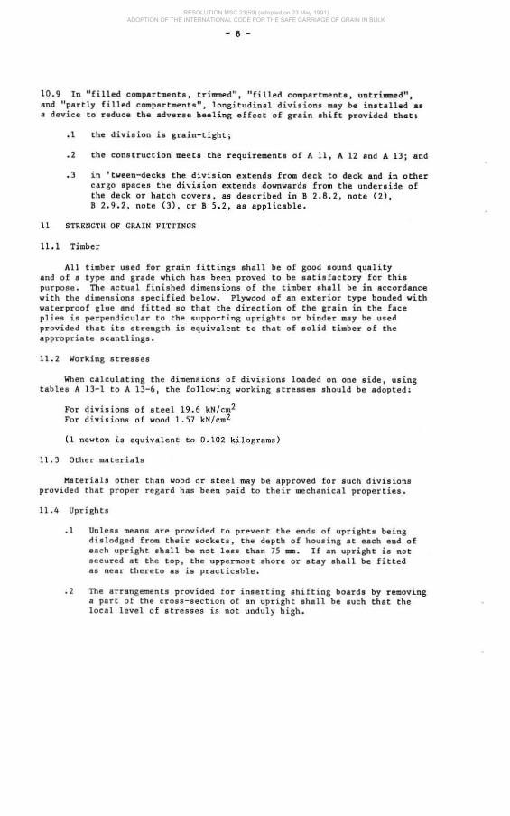
10 .9 In "filled compartments, trimmed", "filled compartments, untrimmed", and "partly filled compartments". longitudinal divisions may be installed 8S
8 device to reduce the adverse heeling effect of grain ahift provided that:
. 1 the division is grain-tight;
.2 the construction meets the requirements of A 11, A 12 and A 13; and
.3 in 'tween-decks the division extends from deck to deck and in other cargo spaces the division extends downwards from the underside of the deck or hatch covers, 8S described in B 2.8.2, note (2), B 2.9.2, note (3), or B 5.2, as applicable.
11 STRENGTH OF GRAIN FITTINGS
11.1 Timber
All timber used for grain fittings shall be of good sound quality and of a t ype and grade which has been proved to be sa tisfactory for this purpose. The actual finished dimensions of the timber shall be in accordance ~ith the dimensions apecified below. Plywood of an exterior t ype bonded with waterproof gl ue and fitted 80 that the direction of the grain in the face plies is perpendicular to the s upporting uprights or binder may be used provided that its s tre ngth i s equivalent to that of solid timbe r of the appropriate scantlings .
11.2 Working stresses
When calculating the dimensions of divisions loaded on one side, using tables A 13-1 to A 13-6, the following working stresses should be adopted:
For divisions of steel 19.6 kN/cm2
For divisions of wood 1.57 kN/cm 2
(1 newton is equivalen t to 0.102 kilograms)
11.3 Other materials
Materials other than wood or steel may be approved for such divisions provided that prope r regard has been paid to their mechanical properties.
11.4 uprights
.1 Unless mea ns are provided to prevent the ends of uprights being dialodged from their sockets, the depth of housing at each end of each upright shall be not less than 75 mm . If an upright is no t secured st the top, the uppermost shore or stay shall be fitted as near thereto 8S is practicable •
. 2 The arrangements provided for inserting shifting boards by removing a part of the c r oss-section of an upright shall be such that the local level of stresses is not unduly high .
RESOLUTION MSC.23(59) (adopted on 23 May 1991) ADOPTION OF THE INTERNATIONAL CODE FOR THE SAFE CARRIAGE OF GRAIN IN BULK
- 8 -
10.9 In "filled compartments, trimmed", "filled c01tlpartment. , untrillKlled", and "partly filled comp&rt~nts". longitudinal divisions cuy be installed a8
a device to reduce the adverse heeling effect of grain shift provided that:
.1 the divi.ion i. grain-tight;
.2 the construction meets the requirementa of A II, A 12 and A 13; aod
.3 in 'tween-decks the division extends from deck to deck and in other cargo spaces the division extends downwards from the underside of the deck or hatch covers, as described in B 2.8.2, note (2), B 2.9.2, note (3), or B 5.2, as applicable.
11 STRENGTIl OF GRAIN FITTINGS
11.1 Timber
All timber used for grain fittings shall be of good sound quality and of a type and grade which has been proved to be satisfactory for this purpose . The actual finished dimensions of the timber ahall be in accordance with the dimensions specified below. Plywood of an exterior type bonded with waterproof glue and fitted 80 that the direction of the grain in the face plies is perpendicular t o the supporting uprights or binder may be used provided that its strength is equivalent to that of aolid timber of the appropriate scantl ings.
11.2 Working at reases
When calculating the dimensions of divisions loaded on one side. using tables A 13-1 to A 13-6. the following working stresses should be adopted:
For divisions of steel 19.6 kN /cm2
For divisions of wood 1.57 kN/cm 2
(1 newton is equivalent to 0 . 102 kilograms)
11 . 3 Other material s
Materials other than wood or steel may be approved for such divisions provided that pro pe r regard has been paid to their mechanica l properties.
11 .4 Uprights
.1 Unless means are provided t o prevent the ends of uprights being dislodged from their sockets, the depth of housing at each end of each upright shall be not less than 75 mm. If an upright is not secured at the top. the uppermost shore or stay shall be fitted as near thereto as is practicable •
• 2 The arrangements provided for inserting shi fting boards by removing a part of the c r oss-section of an upright shall be such that the local level o f atresses is not undul y high.

- 9 -
.3 The maximum bending moment imposed upon an upright supporting a division loaded on one side shall normally be calculated assuming that the ends of the uprights are freely supported. However, if an Administration is satisfied that any degree of fixity assumed will be achieved in practice. account may be taken of any reduction in the maximum bending moment arising from any degree of fixity provided at the enda of the upright.
11.5 Composite section
Where uprights, binders or any other strength members are formed by two separate sections, one fitted on each side of a division and interconnected by through bolts at adequate spacing, the effective section modulus shall be taken 8S the 8um of the two moduli of the separate sections.
11.6 Partial division
Where divisions do not extend to the full depth of the cargo space such divi s ions and their uprights shall be su pported or Btayed 80 8S to be 8S efficient as those which do extend to the full depth of the cargo space.
12 DIVISIONS LOADED ON BOTH SIDES
12.1 Shifting boards
.1 Shifting boards shall have a thickness of not less than 50 mm and shall be fitted grain-tight and where necessary supported by uprights .
• 2 The maximum unsupported span for shifting boards of various thicknesses shall be as fol l ows;
Thickness Maximum unsupported s pan
50 .., 2.5 m 60 rom 3.0 m 70 mm 3.5 m 80 mm 4.0 m.
If thicknesses greater than these are provided the maximum unsupported span will vary directly with the increase i n th ickness .
• 3 The ends of all shifting boards shall be securely housed with 75 mm minimum bearing length.
12.2 Other materials
Divisions formed by using materials other than wood ahall have a strength equivalent to the s h i f ting boards required in A 12.1.
12 . 3 Uprights
.1 Steel upright s used to support divisions loaded on both sides shall have a sec tion modulus given by
RESOLUTION MSC.23(59) (adopted on 23 May 1991) ADOPTION OF THE INTERNATIONAL CODE FOR THE SAFE CARRIAGE OF GRAIN IN BULK
- 9 -
.3 The maximum bending moment imposed upon an upright supporting a division loaded on one side shall normally be calculated assuming that the ends of the uprights are freely supported. However , if an Administration is satisfied that sny degree of fixity assumed will be achieved in practice, account may be taken of any reduction in the maximum bending moment arising from any degree of fixity provided at the ends of the upright.
11.5 Composite section
Where uprights, binders or any other strength members are formed by two separate sections , one fitted on each aide of a division and interconnected by through bolts at adequate spacing, the effective section modulus shall be taken 8S the 8um of the two moduli of the separate sections.
11.6 Partial division
Where divi s ions do not extend to the full depth of the cargo apace such divisions and thei r uprights shall be supported or stayed so as to be as efficient as those which do extend to the full depth of the cargo space.
12 DIVISIONS LOADED ON BOTH SIDES
12.1 Shifting boards
.1 Shifting boards shall have a thickness of not less than 50 mm and shall be fitted grain-tight and where necesssry supported by uprights .
• 2 The maximum unsupported span for shifting boa rds of various thicknesses sha ll be as fol l ows;
Thickness Maximum unsupported s pan
50 mm 2.5 m 60 mm 3.0 m 70 rom 3.5 m 80 mm 4.0 m.
If thicknesses greater than these are provided the maximum unsupported span will var y directly with the increase in th ickness .
• 3 The ends of all shifting boa rds shall be securely hous ed with 75 mm min i mum bearing length.
12.2 Other materials
Divisions formed by using materials other than wood shall have a strength equivalent t o the shifting boards required in A 12.1.
12.3 Uprights
. 1 Steel upri ght s used to support divisions loaded on both sides shall hav e 8 sec tion modulus given by

- 10 -
Where;
W a aection modulus in cubic centimetres: & - horizontal span between uprights in metres.
The section modulus per metre apan WI shall be not less than that given by the formula ;
Where:
hI is the vertical unsupported span in metres and shall be taken as the maximum value of the distance between any two adjacent stays or between a stay and either end of the upright. Where this distance is less than 2.4 m the respective modulus shall be calculated as if the actual value were 2.4 m •
• 2 The moduli of wood uprights shall be determined by multiplying by 12.5 the corresponding moduli for steel uprights. If other materia l s are used their moduli shall be at least t hat requ ired for steel inc reased in proportion t o the r atio of the permissible stresses for steel to that of the material used . In such cases attention shall be paid also to the relative rigidity of each upright to ensure that the deflection is not excessive •
• 3 The horizontal distance between uprights shall be such that the unsupported spans of the shifting boards do no t exceed the maximum span specified in A 12.1.3.
12.4 Shores
.1 Wood shores, when used, shall be in a single piece and shall be securely fixed at each end and heeled agains t the permanent structure of the ship except that they shall not bear directly agains t the side plating of the ship •
• 2 Subject to the provisions of A 12.4.3 and A 12.4.4, the minimum size of wood sho=es shall be as follows:
Length of shore Rec tangular Diameter of in metres section circular section
"" =
Not exceeding 3 III 150 x 100 140 Over 3 m but n o t exceed ing 5 m 150 x 150 165 Qvo< 5 m but not exceeding 6 m 150 x 150 180 Qvo< 6 m but no t exceeding 7 m 200 x 150 190 Ove r m but not exceeding 8 m 200 x 150 200 Exceeding 8 m 200 x 150 215
Shores of 7 III or more in length shall be securely bridged at approximately mid-length.
RESOLUTION MSC.23(59) (adopted on 23 May 1991) ADOPTION OF THE INTERNATIONAL CODE FOR THE SAFE CARRIAGE OF GRAIN IN BULK
- 10 -
Where:
W - section modulus in cubic centimetres: • - horizontal .pan between uprights in metre ••
The .ection modulua per metre apan WI ahall be not leas than that given by the formula;
Wh ere:
hl i s the vertical unsupported span in metres and shall be taken as the maximum value of the distance between any two adjacent stays or between a s tay and ei ther e nd of the upright. Where this distance is 1e88 than 2 . 4 III th e respective modulus shall be calculated as if the actual value were 2.4 Ill •
. 2 The moduli of wood uprights shall be determined by multiplying by 12.5 the corresponding moduli for steel uprights . If other materials are used their moduli shall be at least that required for steel increased in proportion to the ratio of the permissible stresses for steel t o that of the material used. In .uch cases attention shall be paid also to the relative rigidity of each upright to en.ure that the deflection is not excessive •
• 3 The horizontal distance between uprights s ha ll be such that the unsupported spans of the Shifting boards do not exceed the max i mum s pan specified in A 12 . 1.3.
12 .4 Shores
.1 Wood shores, when used, shall be in a singl e piece and shall be securely fixed at each end and hee l ed against the perman en t structure of the sh ip except that they shall not bea r direct ly agains t the side plating of the ship •
. 2 Sub ject to the provisions of A 12.4.3 and A 12 . 4.4, the minimum size of wood sho=es shall be as f o llows:
Length of shore Rectangular Diameter of in metres sec tion c ircular sec tion
~ -Not exceeding 3 III 150 x 100 140 ()ver J m but no t exceeding 5 m 150 x 150 165 Over 5 m but not exceeding 6 m 150 x 150 180 Over 6 m but not exceed ing 7 m 200 x 150 190 Ove< m but not exceeding 8 m 200 x 150 200 Exceeding 8 m 200 x 150 21 5
Shores of 7 m or more in length shall be securely bridged at a pproximately mid-length.

- 11 -
.3 Wh~Q th@ hori~ont.l distance between the uprights differs significantly from 4 m the momenta of inertia of the shores may he changed in direct proportion •
. 4 Where the angle of the shore to the hori~ontal exceeds 10· the next larger shore to that required by A 12.4.2 ahall he fitted provided that in no case ahall the angle between any shore and the horizontal exceed 45 · ,
12.5 Stays
Where stays are used to support divisions loaded on both aide., they shall be fitted horizontally or 8S near thereto 8S practicable, well secured at each end and formed of steel wire rope. The sizes of the wire rope shall be determined assuming that the divisions and upright which the stay supports are uniformly loaded at 4.9 kN/ m2 • The working load so assumed in the stay shal! not exceed one third of its breaking load.
13 DIVISIONS LOADED ON ONE SIDE ONLY
13.1 Longitudinal divi s ions
The load (p) in newtons per metre length of the divisions shall be taken as follows:
.1 Table A 13-1
B(,,)
h(,,) 2 3 4 5 6 7 8' 10
l.lO 8.336 8.826 9.905 12.013 14.710 17.358 20.202 25.939 2.00 13.631 14.759 16.769 19.466 22.506 25.546 28.733 35.~
2. lO 19.466 21.182 23.830 26.870 )).303 33.686 37.265 44.473 3.00 25.644 27.90) 30.891 34.323 38.099 41.874 45.797 53.740 3.lO 31.823 34.568 37.952 41.n7 45 .895 50.014 54.329 63.008 4.00 38.148 41.286 45.013 49.180 53.691 58.202 62.861 72.275 4.lO 44.473 47.955 52.073 56.584 61.488 66. 342 71.392 81.542 5.00 50.847 54.623 59.134 ftI.037 69.284 74.531 79.924 90.810 6. 00 63.498 68. 009 73.256 78. 894 84.877 90.859 96.988 109.344
RESOLUTION MSC.23(59) (adopted on 23 May 1991) ADOPTION OF THE INTERNATIONAL CODE FOR THE SAFE CARRIAGE OF GRAIN IN BULK

Where:
- 12 -
h - height of grain in metres from the bottom of the division. When the cargo apace is filled. the height (h) shall be taken to the overhead deck in way of the divison . In a hatchway or where the distance from a division to 8 hatchway is 1 m or leas, the height (h) ahall be taken to the level of the grain in the hatchway.
B - transverse extent of the bulk grain in metres •
• 2 Linear interpolation within table A 13-1 may be used for i ntermediate values of B and for intermediate values of h when h ia equal to or less than 6.0 m •
• 3 For values of h exceeding 6.0 '01 the load (p) in newtons per metre length of the divisions may be determined from table A 13-2 by entering with the ratio B/h and utilizing the formula:
.4 Table A 13- 2
' /h f I/h f
1- ._-
0.2 1.687 Z.O 3.380 0.3 1 .742 2.2 3.586 0 .4 1.809 2.4 3.792 0.5 1.889 2.6 3.998 0 .6 1.976 ,., 4 .204 0.7 2.064 3.0 4.410 0.8 2.159 :S .5 4.925 1.0 2.358 4.0 5.440 1.2 2.556 5.0 6.469 1.4 2.762 6.0 7.499 1.6 2.968 B.O 9.559
I.' 3.174
13.2 Transverse divisions
The load (p) in newt ons per met re length of the divisons shall be taken as follows~
RESOLUTION MSC.23(59) (adopted on 23 May 1991) ADOPTION OF THE INTERNATIONAL CODE FOR THE SAFE CARRIAGE OF GRAIN IN BULK

h(m)
1.50 2.00 2.50 3.00 3.50 4.00 4.50 5.00 6.00
- 13-
.1 Table A 13-3
2 3
6.570 6.767 10.199 10.787 14 . 318 15.347 18.878 20.251 23.781 25.546 28.930 30 .989 34.274 36.530 39.717 42.218 50.749 53.593
Where:
L(m)
4 5 6 7 8 10 12 14 16
7.159 7.(1.9 8.189 8.728 9.169 9.807 10.199 10.297 10.297 11 .474 12.209 12.994 13.729 14.416 15.445 16.083 16.279 16.279 16.426 17.456 18.437 19.417 20.349 21.673 22.408 22.604 22.604 21.624 22.948 24.222 25.399 26.429 27.900 28.W. 28.930 28.930 27.164 28.733 30.155 31.430 32.558 34.127 35.010 35.255 35.255 32.901 34.667 36.187 37.559 38.736 40.403 41.286 41.531 41.580 38.638 40.501 42.120 43.542 44.767 46.582 47.562 47.856 47 .905 44.473 46.434 48.151 49.622 SO.897 52.809 53.839 54.182 54.231 56.094 58.:ll1 ro.l&. 61.782 63.20'. 65.263 66.440 66.832 66.930
h - height of gr~in in metres from the bottom of the division. When the cargo space is filled, the height (h) shall be taken to the overhead deck in way of the division. In a hatchway, or where the distance from a division to a hatchway i8 1 m or less , the height (h) shall be taken to the level of th e grain in the hatchway.
L - longitudinal extent of the bulk grain in metres .
. 2 Intermediate values of L and intermediate values of h When h is equal to or less than 6.0 m may be determined by linear interpolation using table A 13-3 •
. 3 For values of h exceeding 6.0 m the load (P) in newtons per metre length of th e divisions may be determined from table A 13-4 by entering with the ratio Llh and utilizing the formula.
RESOLUTION MSC.23(59) (adopted on 23 May 1991) ADOPTION OF THE INTERNATIONAL CODE FOR THE SAFE CARRIAGE OF GRAIN IN BULK

- 14 -
.4 Table A 13-4
L/h f L/h f
0.2 1.334 2. 0 1.846 0.3 1.395 2.2 1.853 0.4 1.444 2.4 1.857 0.5 1.489 2.6 1 . 859 0 . 6 1.532 2.8 1.859 0.7 1.571 3.0 1.859 0.8 1.606 3.5 1.859 1.0 1.671 4.0 1.859 1.2 1.725 5.0 1.859 1.4 1. 769 6.0 1.B59 1.6 1.803 8.0 1.859 1.8 1.829
13.3 The total load per unit length of divisions shown in tables A 13-1 to A 13-4 inc lusive may. if considered ne cessary, be assumed to have a trapezoidal distribu tion with height. In such cases, the rea c tion loads at the upper and lower ends of a ver tical member or upright are no t equal. The reaction loads at the upper end expressed as percentages of the total load s upported by the vertical membe r or upright may be taken to be those shown in tables A 13-5 and A 13-6 •
• 1 Table A 13-5: Longitudinal divisions loaded on one side only
h (m)
1.5 2 2.5 3 3.5 4 4.5 5 6 7 8 ,
10
Bearing reaction at the upper end of upright as a percentage of load from A 13.1
• (m)
2 3 4 5 6 7 8
43.3 45.1 45.9 46.2 46.2 46.2 46.2 44. 5 46.7 47.. 47.8 47.8 47.8 47.8 45.4 47.6 48.6 48.8 48 . 8 48.8 48 .8 46.0 48.3 49.2 49.4 49.4 49.4 49.4 46.5 48.8 49 .7 49.8 49.8 49.8 49.8 47.0 49.1 49.9 50.1 50.1 50.1 50.1 47.4 49.4 50.1 50.2 50.2 50.2 50.2 47.7 49.4 50.1 50.2 50.2 50.2 50 . 2 47.9 49.5 50.1 50 . 2 50.2 50.2 50.2 47.9 49 . 5 50.1 50.2 50.2 50 .2 50 .2 47.9 49.5 50.1 50.2 50 . 2 50.2 50.2 47.9 49 .5 50.1 50.2 50.2 50.2 50.2 47.9 49.5 50.1 50.2 50.2 50.2 50.2
B - transverse extent of the bulk grain in metres
10
46.2 47.8 48.8 49.4 49.8 50.1 50.2 50.2 50.2 50.2 50.2 50.2 50.2
For other values of h or B the reaction loads shall be determined by linear interpolation or extrapolation as necessary.
RESOLUTION MSC.23(59) (adopted on 23 May 1991) ADOPTION OF THE INTERNATIONAL CODE FOR THE SAFE CARRIAGE OF GRAIN IN BULK

h(m)
1.5 2 2.5 3 3.5 4 5
" 7 8 9
10
- 15 -
.2 Table A 13-6. Transvers e divisions loaded on one .ide onl y
2
37.3 39.6 41.0 42.1 42.9 43.5 43.9 44.2 44.3 44.3 44.3 44.3
Bearing r eaction at the upper end of upright as a percentage of load from A 13.2
L era)
3 4 5 " 7 8 10 12 14
38.7 39.7 40." 41.4 42.1 42.6 43.6 44.3 44.8 40." 41.4 42.1 42.7 43.1 43." 44.3 44.7 45.0 41.8 42.5 43.0 43.5 43.8 44.2 44.7 45.0 45.2 42.8 43.3 43.8 44.2 44 . 5 44.7 45.0 45.2 45.3 43.5 43.9 44.3 44." 44.8 45.0 45.2 45.3 45.3 44.0 44.4 44.7 44.9 45.0 45.2 45.4 45.4 45.4 44.3 44 ." 44.8 45.0 45.2 45.3 45.5 45.5 45 .5
· 44.5 44.8 45.0 45.2 45.3 45.4 45." 45.6 45.6 44." 44.' 45.1 45.3 45.4 45.5 45." 45.6 45.6 44." 44.9 45.1 45.3 45.4 45.5 45." 45." 45." 44." 44.9 45.1 45.3 45.4 45.5 45." 45.6 45.6 44." 44. ' 45.1 45.3 45.4 45.5 45.6 45." 45.6
L'" longitudinal. extent of the bulk grain in aetres
1"
45.0 45.2 45.2 45.3 45.3 45.4 45.5 45.6 45 .6 45 ." 45." 45."
For other values of h or L the reaction loads shalt be determined by linear interpola tion or extrapolation as necessary •
• 3 the strength of the end connections of such verti ca l members or uprights may be calculated on the basis of the maximum load likely to be imposed at either end. These loads are as follows:
Longitudinal divisions
Maximum load at the top 50% of the appropriate total load from A 13.1
Maximum load at the bottom 55% of the appropriate t0tal load from A 13.1
Transverse divisions
Maximum load at the top 45% of the appropriate total load from A 13.2
Maximum l oad at the bottom 60% of the appropriate total load from A 13.2
.4 The thickness of horizon ta l wooden boards may also be determined having regard to the vertical distribution of the loading represented by tables A 13-5 and A 13-6 and in such cases
~ loaJthP~X_k~,,-. x 20 91.8
RESOLUTION MSC.23(59) (adopted on 23 May 1991) ADOPTION OF THE INTERNATIONAL CODE FOR THE SAFE CARRIAGE OF GRAIN IN BULK

- 16 -
Where:
t thickness of board in millimetrea a ~ horizonta l span of the board, i . e . distance between
uprights in metres h 5 head of grain to the bottom of the division in metre s p = total load per unit length de rived from the tables in
newt ons k factor dependent upon vertical distribution of the
loading.
When the vertical distribution of the load i ng is assumed to be uniform, i.e. rectangular, k shall he taken as equal to 1.0. For a trapezoidal distribution
k = 1.0 + 0 .06 (50 - R)
Where:
R is the uppe r end bearing reaction taken from table A 13- 5 or A 13-6,
. 5 Stays or shores
The sizes of stays and shores shall be 80 determined that the loads derived from tables A 13-1 to A 13-4 inclusive shall not exceed one third of the breaking loads.
14 SAUCERS
l~.l For the purpose of reducing the heeling moment a saucer may be used in place of a longitudinal division in way of a hatch opening only in a "filled, trimmed" compartment as defined in A 2.2, except in the case of linseed and other seeds having similar properties, where a sauCer may not be substituted for a longitudinal division. If a longitudinal division is provided, it shall mee t the requirements of A 10.9.
14.2 The depth of the saucer, measured from the bottom of the saucer to the deck line, shall be as fol lows~
.1 For ships with a mou lded breadth of up to 9. 1 m, not leas than 1.2 m •
. 2 For ships with a moulded breadth of 18 .3 m or more, not less than 1.8 m •
. 3 For sh i ps with a moulded breadth between 9.1 m and 18.3 m, the minimum depth of the saucer shall be calculated by interpolation.
RESOLUTION MSC.23(59) (adopted on 23 May 1991) ADOPTION OF THE INTERNATIONAL CODE FOR THE SAFE CARRIAGE OF GRAIN IN BULK
- 16 -
Where:
t - thickness of board in millime tree a - horizontal span of the board, i.e. distance between
uprights in metres h head of grain to the bottom of the division in metres p - total load per unit length derived from the tables in
ne~tons
k - factor dependent upon vertical distribution of the loading.
When the vertical distribution of the loading ia assumed to be uniform, i.e. rectangular, k shall be taken as equal to 1.0. For a trapezoidal distribution
k - 1.0 + 0.06 (50 - R)
Where :
R ia the upper end bearing reaction t aken fr~ table A 13-5 or A 13-6 .
• 5 Stays or shores
The sizes of stays and shores shall be 80 determined that the loads derived f rom tables A 13-1 to A 13-4 inclusive shall not exceed one third of the breaking loads.
14 SAUCERS
14.1 For the purpose of reducing the heeling moment a saucer may be used in place of a longitudinal division in way of a hatch opening only in a "fi lled, trimmed" compartment as defined in A 2.2, except in the case of linseed and other seeds having similar properties, where a saucer may not be substituted for a longitudinal division. If a longitudinal division is provided, it shall meet the requirements of A 10.9.
14.2 The depth of the saucer, measured from the bottom of the saucer to the deck line. shall be as follo~s:
. 1 For ships ~ith a moulded breadth of up to 9.1 m, not less than 1. 2 m .
. 2 For ships with s moulded breadth of 18.3 m or more, not less than 1.8 m .
. 3 For ships with a moulded breadth bet~een 9.1 m and 18.3 =, the minimum depth of the saucer shall be calcu lated by interpolation.

- 17 -
14.3 The top (mouth) of the saucer shall be formed by the underdeck structure in way of the hatchway, i.e. hatch side girders or coamings and hatch end beams. The saucer and hatchway above shall be completely filled with bagged grain or other suitable cargo laid down on a separation cloth or its equivalent and stowed tightly against adjacent structure so as to have a bearing contact with such structure to a depth equal to or greater than one half of the depth specified in A 14.2. If hull structure to provide such bearing surface is not available. the saucer shall be fixed in position by steel wire rope, chain, or double steel strapping ss specified in A 11.1.4 and spaced not more than 2.4 m apart.
15 BUNDLING OF BULK GRAIN
As an alternative to filling the saucer in a "filled, trirmned" compartment with bagged grain or other suitable cargo a bundle of bulk grain may be used provided that:
.1 The dimensions and means for securing the bundle in place are the same as specified for a saucer in A 14.2 and A 14.3 •
• 2 The saucer is lined with a material acceptable to the Administration having a tensile strength of not less than 2,687 N per 5 cm strip and which is provided with suitable means for securing at the top •
• 3 As an alternative to A 15 . 2, a material acceptable to the Administration having a tensile strength of not less than 1,344 N per 5 cm strip may be used if the saucer is constructed as follows:
.3.1 Athwartship lashings acceptable to the Administration shall be placed inside the saucer formed in the bulk grain at intervals of not more than 2.4 m. These lashings shall be of sufficient length to permit being drawn up tight and secured at the top of the saucer .
• 3.2 Dunnage not less than 25 mm in thickness or other suitable material of equal strength and between 150 mm and 300 mm in width shall be placed fore and aft over these lashings to prevent the cutting or chafing of the material which shall be placed thereon to line the saucer •
• 4 The saucer shall be filled with bulk grain and secured at the top except that when using material approved under A 15.3 further dunnage shall be laid on top after lapping the material before the saucer is secured by setting up the lashings .
. 5 If more than one sheet of material is used to line the saucer they shall be joined at the bottom either by sewing or by a double lap .
. 6 The top of the saucer shall be coincidental with the bottom of the beams when these are in place and suitable general cargo or bulk grain may be placed between the beams on top of the saucer.
RESOLUTION MSC.23(59) (adopted on 23 May 1991) ADOPTION OF THE INTERNATIONAL CODE FOR THE SAFE CARRIAGE OF GRAIN IN BULK
- 17 -
14.3 The top (mouth) of the saucer shall be formed by the underdeck structure in way of the hatchway, i.e. hatch side girders or coamings and hatch end beams. The saucer and hatchway above shall be completely filled with bagged grain or other suitable cargo laid down on a separation cloth or its equivalent and stowed tightly against adjacent structure so as to have a bearing contact with such structure to a depth equal to or greater than one half of the depth specified in A 14.2. If hull structure to provide such bearing surface is not available, the saucer shall be fixed in position by steel wire rope, chain, or double steel strapping ss specified in A 17.1.4 and spaced not more than 2.4 m apart.
15 BUNDLING OF BULK GRAIN
As an alternative to filling the saucer in a "filled, trirmned" compartment with bagged grain or other suitable cargo a bundle of bulk grain may be used provided that:
.1 The dimensions and means for securing the bundle in place are the same as specified for a saucer in A 14.2 and A 14.3 •
• 2 The saucer is lined with a material acceptable to the Administration having a tensile strength of not less than 2,687 N per 5 cm strip and which is provided with suitable means for securing at the top •
• 3 As an alternative to A 15 . 2, a material acceptable to the Administration having a tensile strength of not less than 1,344 N per 5 cm strip may be used if the saucer is constructed as follows:
.3.1 Athwartship lashings acceptable to the Administration shall be placed inside the saucer formed in the bulk grain at intervals of not more thsn 2.4 m. These lashings shall be of sufficient length to permit being drawn up tight and secured at the top of the saucer .
• 3.2 Dunnage not less than 25 rom in thickness or other suitsble material of equal strength and between 150 mrn and 300 mm in width shall be placed fore and aft over these lashings to prevent the cutting or chafing of the material which shall be placed thereon to line the Baucer •
• 4 The saucer shall be filled with bulk grain and secured at the top except that when using material approved under A 15.3 further dunnage shall be laid on top after lapping the material before the saucer is secured by setting up the lashings .
. 5 If more than one sheet of material is used to line the saucer they shall be joined at the bottom either by sewing or by a double lap .
. 6 The top of the saucer shsll be coincidental with the bottom of the beams when these are in place and suitable general cargo or bulk grain may be placed between the beams on top of the saucer.

- 18 -
16 OVERS TOWING ARRANGEMENTS
16.1 Where bagged grain or other suitable cargo is utili%ed for the purpose of securing "partly filled" compartments, the free grain surface shall be level and shall be covered with a separation cloth or equivalent or by a suitable platform. Such platform shall consist of bearers spsced not more than 1.2 m apart and 25 mm boards laid thereon spaced Dot more than 100 mm apart. Platforma may be conatructed of other materials provided they are deemed by the Administration to be equivalent.
16 . 2 The platform or separation cloth shall be topped off with bagged grain tightly stowed and extending to a height of not less than one sixteenth of the maximum breadth of the free grain surface or 1.2 m, whichever is the greater.
16.3 The bagged grain shall be carried in sound bags which shall be well filled and securely closed.
16 .4 Instead of bagged grain, other suitable cargo tightly stowed and exerting at least the same pressure as bagged grain stowed in accordance with A 16.2 may be used .
17 STRAPPING OR LASHING
When, in order to eliminate heeling moments in partly filled compartments, strapping or lashing is utilized, the securing shall be a ccomplished as follows:
.1 The grain shall be trimmed and levelled to the extent that it is very slightly crowned and covered with burlap separation cloths, tarpaulins or the equivalen t •
• 2 The separation cloths snd /or tarpaulins shall overlap by at least 1.8 m •
• 3 TWo solid floors of rough 25 mm by 150 rom to 300 rom lumber shall be laid with the top- floor running longitudinally and nailed to an athwartships bottom floor. Alternat ively , one solid floor of 50 mm lumber, running longitudinally and nailed over the top of a 50 mm bottom bearer not less than 150 rom wide, may be used. The bottom bearers shall extend the full breadth of the compar tment and shall be spaced no t more than 2.4 m apart. Atrangements utilizing other materials and deemed by the Administration to be equivalent to the foregoing may be accepted •
• 4 Steel wire rope (19 mm diameter or equivalent), double steel strapping (50 rom x 1.3 mm and having a breaking load of at least 49 kN), or chain of equivalent s trength, each of which ahall be set tightly by means of a 32 rom turnbuckle, may be used for lash i ngs. A winch tightener, used in conjunction with a locking srm, msy be substituted for the 32 mm turnbuckle when steel strapping is used , provided suitable wrenches are available for setting up as necessary. When steel strapping is used, no t less than three crimp seals shall be used for securing the ends. When wire is used, not less than four c lips shall be used for forming eyes in the lashings.
RESOLUTION MSC.23(59) (adopted on 23 May 1991) ADOPTION OF THE INTERNATIONAL CODE FOR THE SAFE CARRIAGE OF GRAIN IN BULK
- 18 -
16 OVERS TOWING ARRANGEMENTS
16.1 Where bagged grain or other auitable cargo is utilized for the purpose of securing "partly filled ll compartments, the free grain surface shall be level and shall be covered with a separation cloth or equivalent or by a suitable platform. Such platform ahall consist of bearers .p.ced not more than 1.2 m apart and 25 mm boards laid thereon spaced Dot more than 100 mm apart. Platforms may be constructed of other materials provided they are deemed by the Administration to be equivalent.
16 . 2 The platform or separation cloth shall be topped off with bagged grain tightly stowed and extending to a height of not less than one sixteenth of the maximum breadth of the free grain surface or 1.2 m, whichever is the greater.
16.3 The bagged grain shall be carried in sound bags which shall be well filled and securely closed.
16 . 4 Instead of bagged grain, other suitable cargo tightly stowed and exerting at least the same pressure aa bagged grain stowed in accordance with A 16.2 may be used.
17 STRAPPING OR LASHING
When, in order to eliminate heeling moments in partly filled compartments, strapping or lashing is utilized, the securing shall be accomplished as follows:
.1 The grain shall be trimmed and levelled to the extent that it is very slightly crowned and covered wi th burlap separation cloths, tarpaulins or the equivalent •
• 2 The separation cloths snd /or tarpaulins shall overlap by at least 1.8 m •
• 3 Two solid floors of rough 25 mm by 150 moo to 300 mm lumber shall be laid with the top- floor running longitudinally and ns iled to an athwartships bottom floor. Alternat ively , one solid floor of 50 mm lumber, running l ongitudinally and nailed over the top of s 50 mm bottom bearer not less than 150 mm wide. may be used. The bottom bearers shall extend the full breadth of the compartment and shall be spaced no t more than 2.4 m apart. Arrangements utilizing other materials and deemed by the Administration to be equivalent to the foregoing may be accepted •
. 4 Steel wire rope (19 mm diameter or equivalent), double steel strapping (50 mm x 1.3 mm and having a breaking load of at least 49 kN), or chain of equivalent strength, each of which shall be set tightly by means of 8 32 mm turnbUCkle, may be used for lash ings . A winch tightener, used in conjunction with a locking arm, msy be substituted for the 32 mm turnbuckle when steel strapping is used , provided suitable wrenches are available for setting up as necessary. When steel strapping is used, no t less than three crimp seals shall be used for securing the ends. When wire is used, not less than four c lips shall be used for forming eyes in the lashings.

- 19 -
.5 Prior to the completion of loading the lashing shall be positively attached to the framing at a point approximately 450 mm below the anticipated final grain surface by means of either a 25 ~ shackle or beam clamp of equivalent strength •
• 6 The lashings shall be spaced not more than 2.4 m apart and each shall be supported by a bearer nailed over the top of the fore and aft floor. This bearer shall consist of lumber of not leaa than 25 mm by 150 mm or its equivalent and ahall extend the full breadth of the compartment •
• 7 During the voyage the strapping shall be regularly inspected and set up where necessary.
18 SECURING WITH WIRE MESH
When, in order to eliminate grain heeling moments in "partly filled" Compartments, strapping or lashing is utilized, the securing may, as an alternative t o the method described in A 17, be accomplished as follows:
.1 The grain shall be trimmed and levelled to the extent that it is very slightly crowned slang the fore and aft centreline of the compartment •
• 2 The entire surface of the grain shall be covered with burlap separation cloths, tarpaulins, or the equivalent. The covering materia l shall have a tensile strength of not less than 1,344 N per 5 cm strip •
• 3 Two laye rs of wire reinforcement mesh shall be l aid on top of the burlap or other covering. The bottom layer is to be laid athwartships and the top layer is to be laid longitudinally. The lengths of wire mesh are to be overlapped at leas t 75 rom. The top layer of mesh is to be positioned over the bottom layer in such a manner that the squares formed by the alternate layers measure approximately 75 moo by 75 mm. The wire reinforcement mesh is the type used in reinforced concrete construction. It is fabricated of 3 mm diameter steel wire having a breaking strength of not less than 52 kN/cm2 , welded in 150 mm x 150 mm squares. Wirp. mesh having mill scale may be used but mesh having loose, flsking rus t may not be used •
• 4 The boundaries of the wire mesh, at the port and starboard side of the compartment, shall be retained by wood planks 150 mm x 50 mm .
• 5 Hold-down lashings, running from side to side across the compartment, shall be spaced not more than 2.4 m apart except that the first and the last las hing shall not be wore than 300 rom from the forward or after bulkhead, respectively. Prior to the completion of the loading , each lashing shall be positively attached t o the framing at a point approximately ~50 rom below the anticipated final grain aurface by means of either a 25 rom shackle or beam clamp of equivalent strength. The lashing shall be led from this point over the top of the boundary plank described in A 18.1.4, which has the function of distributing the downward pressure exerted by the lashing . Two layers of 150 mm x 25 mm planks shall be laid athwsrtships centred beneath each lashing and extending the full breadth of the compartment.
RESOLUTION MSC.23(59) (adopted on 23 May 1991) ADOPTION OF THE INTERNATIONAL CODE FOR THE SAFE CARRIAGE OF GRAIN IN BULK
- 19 -
.5 Prior to the completion of load ing the lashing shall be positively attached to the framing at a point approximately 450 mm below the anticipated final grain surface by means of either a 25 mm shackle or beam c lamp of equivalent strength •
• 6 The lashings shall be spaced not more than 2.4 m apart snd each shall be supported by a bearer na iled over the top of the fore and aft floor . Thia bearer shall consist of l umber of not less than 25 mm by 150 mm or its equivalent and ahall extend the full breadth of the compartment •
• 7 During the voyage the strapping shall be regularly inspected and set up where necessary.
18 SECURING WITH WIRE MESH
When, in order to eliminate grain heeling moments in "partly filled" compartments, strapping or lashing is utilized, the securing may, as an alter native to the method described in A 17, be accomplished as follows:
.1 The grain shall be trimmed and levelled to the extent that it is very slightly crowned along the fore and aft centreline of the compartment •
• 2 The entire surface of the grain shall be covered with burlap separation cloths, tarpaulins, or the equivalent. The covering material shall have a tensile strength of not less than 1,344 N per 5 em strip •
• 3 Two layers of wire r einforcement mesh shall be l aid on top of the burlap or other covering. The bottom layer is to be laid athwartships and the top layer is to be laid longitudinally . The lengths of wire mesh are to be overlapped at least 75 mm. The top layer of meah ia to be positioned over the bottom layer in such a manner that the squares formed by the alternate layers measure approximately 75 rom by 75 mm. The wire reinforcement mesh is the type used in reinforced concrete construction. It is fabricated of 3 mm diameter steel wire having a breaking strength of not less than 52 kN/cm2 , welded in 150 mm x 150 mm squares. Wirp. mesh having mill scale may be used but mesh having loose, flaking rust may not be used •
• 4 The boundaries of the wire mesh, at the port and starboard side of the compartment, shall be retained by wood planks 150 mm x 50 mm .
• 5 Hold-down lashings, running from side to side across the compartment, shall be spaced not more than 2.4 m apart except that the first and the last laahing shall not be more than 300 mm from the forward or after bulkhead , respectively. Prior to the completion of the loading, each lashing shall be positively attached t o the framing at a point approximately 450 mm below the anticipated final grain surface by means of either a 25 mm shackle or beam clamp of equ i valent strength . The lashing shall be led from this point over the top of the boundary plank described in A 18.1.4, which has the fun c tion of distributing the downward pressure exerted by the lashing. Two layers of 150 mm x 25 mm planks shall be laid athwartshipa centred beneath ea ch lashing and extending the full breadth of the compartment.

- 20 -
.6 The hold-down lashings shall consist of steel wire rope (19 mm diameter or equivalent) , double steel strapping (50 mm x 1.3 mm and having a breaking load of at least 49 kN). or chain of equivalent strength, each of which shall be set tight by meana of a 32 mm turnbuckle. A winch tightener, used in conjunction with a locking arm, may be substituted for the 32 mm turnbuckle when steel strapping i. used, provided .uitable wrenches are available for .etting up ss necesssry. When steel strapping i. u.ed , not less than three crimp seals shall be used for securing the ends. When wire r ope is used, not less than four clips shall be used for forming eyes in the lashings •
• 7 During the voyage the hold-down lashings shall be regularly inspected and set up where necessary.
RESOLUTION MSC.23(59) (adopted on 23 May 1991) ADOPTION OF THE INTERNATIONAL CODE FOR THE SAFE CARRIAGE OF GRAIN IN BULK
- 20 -
.6 The hold-down la.hings .hall consist of .teel wire rope (19 mm diameter or equivalent), double ateel strapping (50 em x 1.3 em and having a breaki ng load of at leaat 49 kN), or chain of equivalent atrength, each of which ahall be aet tight by .eana of a 32 mm turnbuckle . A winch ti gh t ener, uaed in conjunction with a locking arm, may be substituted for the 32 mm turnbuck l e when a t ee l atr.pping ia uaed, prov i ded auitable vrenchea are available for aet ting up aa necessary. When steel strapping i. u.ed, not l e.s than three cri~p seal. shall be u.ed for .ecuring the enda. When wire rope is used, not lea. than four cl ip •• hall be used for forming eye. in the lashing ••
. 7 During the voyage the hold-down lashings shall be regularly inspected and set up where necessary.

- 21 -
PART B
CALCULATION OF ASSUMED HEELING MOMENTS AND CENERAL ASSUMPTIONS
1 GENERAL ASSUMPTIONS
1 . 1 For the purpose of calculating the adverse heeling moment due to a shift of cargo surface in ships carrying bulk grain it shall be assumed that:
.1 In filled compartments which have been trimmed in accordance with A 10.2, a void exis t s under all boundary surfaces having an inclination to the horizontal less than 30·and that the void is parall e l to the boundary surface having an average depth calculated according to the formula:
Vd ~ Vdl • 0 . 75 (d - 600) mro
Where ~
Vd - average void depth in millimetres:
Vdl a standard void depth from table B 1-1 below:
d actual girder depth in m,illimetres.
In no case shall Vd be assumed to be less than 100 ~.
Table B 1-1
Distance from hatch end or hatch side to boundar y of
compartment Standard void depth Yd.
me tres mill imetres
0.5 570 1.0 530 1.5 500 2.0 480 2.5 450 3.0 440 3.5 430 4 .0 430 4.5 430 5.0 430 5.5 450 6.0 470 6.5 490 7.0 520 7.5 550 8.0 590
RESOLUTION MSC.23(59) (adopted on 23 May 1991) ADOPTION OF THE INTERNATIONAL CODE FOR THE SAFE CARRIAGE OF GRAIN IN BULK

- 22 -
Notes on table B I-I:
(1) For boundary distances greater than 8.0 m the standard void dep th (Vdl) shall be linearly extrapolated at 80 mm increase for each 1.0 m increase in length.
(2) In the corner area of a compartment the boundary distance shall be the perpendicular distance from the line of the hatch side girder or the line of the hatch end beam t o the boundary of the compartment, whichever is the greater. The girder depth (d) shall be taken to be the depth of the hatch side girder or the hatch end beam, whichever is the less.
(3) Where there is a raised deck clear of the hatchway the average void depth measured from the underside of the raised deck shall be calculated using the standard void depth in association with a girder depth of the hatch end beam plus the height of the raised deck •
• 2 Within filled hatchways and in addition to any open void within the hatch cover there is a void of average depth 150 moo measured down to the grain surface from the lowest part of the hatch cover or the top of the hat ch side coaming, whichever is the lower •
. 3 In a "filled compartment, untrimmed" which is exempted from trimming outside the periphery of the hatchway by the prov isions of A 10 . 3.1, it shall be assumed that the surfsce of the grain after loading will alo pe into the void space underdeck, in all directions, at an angle of 30 ' to the horizontal from the edge of the opening which establishes the void •
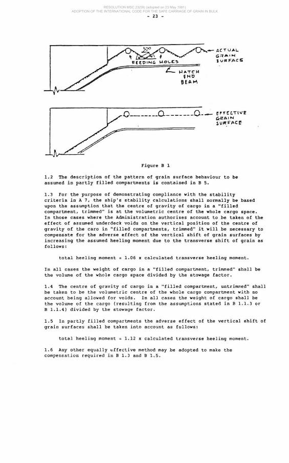
• 4 In a "filled compartment, untrimmed" which is exempted from trimming in the ends of the compartment under the provisions of A 10.3.2, it shall be assumed that the surface of the grain after loading will slope in all directions away from the filling area at an angle of 30 · from the lower edge of the hatch end beam. However, if feeding holes are provided in the hatch end beams in accordance with table B 1-2, then the surface of the grain after l oading shall be assumed to slope in all directions, at an angle of 30· from a line on t he ha t ch end beam which is the mean of the peaks and valleys of the actual grain surface as shown i n figure B 1 .
Table B 1-2
Oiameter (1lID'I) Area Spacing (metres) Mi nimum ,(cm 2) Max imum
90 63.6 .60
I 100 78.5 . 75 110 95.0 .90 120 113.1 1.07
, 130 133.0 1.2 5
I V.O 154 . 0 1.4 5 150 177 .0 1.67
I 160 201.0 1.90
! 170 or above 227.0 2.00 maximum
RESOLUTION MSC.23(59) (adopted on 23 May 1991) ADOPTION OF THE INTERNATIONAL CODE FOR THE SAFE CARRIAGE OF GRAIN IN BULK
- 23 -
__ ACTUAL
G-:1''''''toi IvP:FACti
0 ______ 0-_______ 0. __ e"'"fC.Tt .... ! er;tAIN lV.lf.~.ACe
Figure 11 1
1.2 The description of the pattern of grain surface behaviour to be assumed in partly filled compartments is contained in 11 5.
1.3 For the purpose of demonstrating compliance with the stability criteria in A 7. the ship's stability calculations shall normally be based upon the assumption that the centre of gravity oC cargo in a "filled compartment. trimmed" is at the vol ume tric centre of the vhole cargo space. In those cases where the Administration authori~es account to be taken of the effect of assumed underde ck vo ids on the vertical pos ition of the centre of gravity of the caro in "filled compartments, trimmed" it will be necessary to compensate for the adverse effect of the vertical shift of grain surfaces by increasing the assumed heeling moment due to the tran6Ver&e shift of grain a& follows:
total heeling moment: 1. 06 • calculated transverse heeling moment.
In all cases the weight of cargo in a "filled compartment. trinvned" shall be the volume of the whole cargo space divided by the stowage factor.
1.4 The centre of gravity of cargo in a "filled compartment. untrimmed" shall be taken to be the volumetric centre of the whole cargo compartment with no account being allowed for voids . In all cases the weigh t of cargo shall be the volume of the cargo (resulting from the assumpt~ons stated in 11 1.1.3 or B 1.1.4 ) divided by the stowage factor.
1.5 In partly filled compartments the adverse effect of the vertical shift of grain surfaces shall be taken into account as follows:
total heeli ng momen t : 1.12 x calculated transverse heeling moment.
1.6 Any other equally ~[fective method may be adopted to make the compensation required in B 1 .3 and B 1.5.
RESOLUTION MSC.23(59) (adopted on 23 May 1991) ADOPTION OF THE INTERNATIONAL CODE FOR THE SAFE CARRIAGE OF GRAIN IN BULK

- 24 -
2 ASSUMED VOLUMETRIC HEELING HOHENT OF A FILLED COMPARTMENT, TRIMMED
General
2.1 The pattern of grain surface movement relates to 8 transverse section across the portion of the compsrtment being considered and the resultant heeling moment should be multiplied by the length to obtain the total moment for that port ion.
2.2 The assumed transverse heeling moment due to grain shifting is a consequence of final changes of s hape and position of voids sfter grain has moved from the high side to the low side.
2.3 The resulting grain surface a fter shifting shall be assumed to be at 15° to th e horizonta l .
2.4 In calcu lat ing the maximum void area that can be formed against a longitudinal structural member, the effects of any horizontal s urfaces, e.g. flanges or face bars, shall be ignored .
2 . 5 The total areas of the initial and final voids shall be equal.
2.6 Longi tudina l st ructural members which are grain- tight may be considered effect ive over the ir full depth except where the y are provided as 8 device to reduce t he adve r se effec t of gr ain shif t, in which case the provis i ons of A 10.9 shal l apply.
2.7 A discontinuous longitudinal division may be considered effec tive over i ts full length.
Assumpt ions
In the following paragraphs it i s assumed that the total heeling moment for a compar tmen t is obtained by adding the results of separate consideration of the fol l owing portions;
2.8 Before and abaft hatchways:
. 1 If a compartment has two or more ma in hatchways throu gh which loading may take place , the depth of the under deck void f or the por tion or portions between such hatchways s ha ll be determined using the fore and aft dis tance to t he midpoint between the hatchways.
RESOLUTION MSC.23(59) (adopted on 23 May 1991) ADOPTION OF THE INTERNATIONAL CODE FOR THE SAFE CARRIAGE OF GRAIN IN BULK
- 24 -
2 ASSUMED VOL1JKETRIC HEELING MOMENT OF A FILLED COMPARTMENT, TRIMMED
General
2.1 The pattern of gra i n surface movement relates t o a transvers e section s c ros s t he portion of the compartment being considered and t he resultant heeling moment s hould be multiplied by the length t o obtain the t otal moment for that portion.
2.2 The as sumed transve rse hee ling moment due to gr a in shifting is a consequence of final changes of shape and position of v oi ds after grain has moved h 'om the high aide to the low side.
2.3 The resulting grain surface a fter shift ing sha ll be assumed to be at 15 - t o the hori~ontal.
2.4 In calcu l ating the maximum void area that can be formed against a longi tudinal structura l member , the effects of any horizontal surfaces. e.g . flanges or face bars, shall be i gnor ed.
2 . 5 The to t al areas of the initial and final voida shall be equal.
2 . 6 Longitudinal st r uctural members whi ch are grain-tight may be conside r ed effective over their full depth except where they are provided as a device to red uce the adverse effec t of grain shift, in which case the provisions of A 10.9 shal l apply.
2 . 7 A di scontinuous longitudinal division may be considered effec t ive over its fu ll length.
Assumptions
In the following paragraphs it is assumed that the total heeling moment for a compartmen t i s ob tained by adding the results of separate consideration of the fol l owi ng portions :
2.8 Before and abaft hatchways:
. 1 If a compartmen t has t wo or more main hatchways through wh ich loading may take place, the depth of the underdeck void for the portion o r portions between such ha tchways shall be determined using t he fore a nd aft distance to the midpoint between the hatchways.

2.9 •
- 25 -
.2 Af~er the assumed shift of grain the final void pattern shall be as shown in figure B 2 - 1 .
T --~----- -----------!.i ~ :::j---kI .. " ·d. t ". ... "".
~~o
Figure B 2-1
Notes on figure B 2 - 1
(1) If the maximum void area which can be formed against the girder at B is less than the initial area of the void under AB. i.e. AB x Vd, the excess area shall be assumed to transfer to the final void on the high side .
(2) If, for example. the longitudinal division at C 15 ODe which has been provided in accordance with A 10.9. it shall estend to at least 0.6 m below D or E whichever gives the greater depth.
. 1 In and abreast of hatchways without longitudinal division:
After the assumed shift of grain the final void pattern shall be as shown in figure B 2- 2 or figure B 2-3:
c / no mm phnill" apc~~ ",nhlll l ht h~l ( h WOC!
o
.L .',--=-_...:"'1 vo '
, T ' - --
Figure B 2 - 2
Ho~es on figu re B 2-2:
(1) AB
(2) CD
Any area in excess of that whi ch can be formed against the girder at B shall transfer to the final void area In the hatchway.
Any area in eXCesS of that which can be formed against the girder a t t shall transfer to the final void area on the high side.
RESOLUTION MSC.23(59) (adopted on 23 May 1991) ADOPTION OF THE INTERNATIONAL CODE FOR THE SAFE CARRIAGE OF GRAIN IN BULK

- 26 -
.2 In and abreast of hatchways with longitudinal division:
c o 1 -
H
150 ...... ph" . ny Orr" .o.cj ' ... 11",. lho IuICi\"«;.- , -, -
• G
I Figure B 2- 3
Hotes on figure B 2-]1
(1) The excess yoid area fr om AB shall transfer to the low side half of the hatchway in which two separate final void areas viII be formed viz. one agaInst the centreline division and the other against the hatch side coaming and girder on the high side.
(2) If a bagged saucer o r bulk bundle is formed in a hatchway it shall be assumed for the purpose of calculating the transverse heeling moment that such a device is at least equivalent to the cent~eline division.
(3) If the centreline division is one which has been provided in accordance wi th A 10.9. it shall extend to at least 0.6 m below H or J whichever gives the greater depth.
Compartment§ loaded in combination
The followi~g paragraphs describe the pattern of void behaviour which shall be assumed when compartments are loaded in combination:
2.10 Without effective centreline di v isions:
.1 Under the upper deck - as f or the single deck arrangement described in B 2.8.2 and B 2.9.1 .
• 2 Under the second deck - the area of void available for transfer from the low side. i.e. original void area less area against the hatch side girder, shall be assumed to transfer as follows:
one half to the upper de c k hatchway and one quarter each to the high side under the upper and second deck •
• 3 Under the third and lower decks - the void areas available for transfer from the low s i de of each of these decks shall be assumed to transfer in equal quantities to all the voids under the decks on the high side and the void in the upper deck h atchway.
RESOLUTION MSC.23(59) (adopted on 23 May 1991) ADOPTION OF THE INTERNATIONAL CODE FOR THE SAFE CARRIAGE OF GRAIN IN BULK

- 27 -
2.11 With effective centreline divisions which extend into the upper deck hatchway:
.1 At all deck levels abreast of the division the void areas available for tr .. nsfer from the low side shall be assumed to transfer to the void under the low side half of the upper deck hatchway •
• 2 At the deck level immediately below the bottOlll of the division the void area available for transfer from the low aide shall be assumed to transfer as follows.
one half to the void under the low side half of the upper deck hatchway and the remainder in equal quantities to the voids under the decks on the high side •
• 3 At deck levels lower than those described in B 2.11.1 or B 2.11.2, the void area available for transfer from the low aide of each of those decks shall be assumed to transfer in equal quantities to the voids in each of the two halves of the upper deck hatchway on each side of the division and the voids under the decks on the high aide.
2 .12 With effective centreline divisions which do no t extend into the upper de ck hatchway:
since no horizontal transfer of voids may be assumed to take place st the same deck level as the division, the void area available for transfer from the low side at this level shall be assumed to transfer above the division to voids on the high side in accordance with the principles of B 2.10 and B 2.11.
3 ASSUMED VOLUMETRIC HEELING MOMENT OF A FILLED COMPARTMENT, UNTRIMMED
3.1 All the provision for "filled comparttuents, trimmed" set forth in B 2 shall also apply to "filled compartments, untrilllD'led" except as noted below.
3.2 In "filled compartments, untrimmed" which are exempted from trimming outside the periphery of the hatchway under the provisions of A 10.3.1:
.1 the resulting grain surface after shifting shall be assumed to be at an angle of 25 - to the horizontal. However, if in any section of the compartment, forward, aft, or abreast of the hatchway the mean transverse area of the void in that section is ~qual to or less than the area which would obtain by application of B 1.1, then the angle of grain surface after shifting in that section shall be assumed to be 15- to the horizontal; and
.2 the void area at any transverse section of the compartment shall be assumed to be the same both before and after the grain shift. i.e. it shall be assumed that additional feeding does not occur at the time of the grain shift.
3.3 In "filled compartments, untrimmed" wh ich are exempted from t rimmi ng in the ends, forward and aft of the hatchway. under the provisions of A 10.3.2:
RESOLUTION MSC.23(59) (adopted on 23 May 1991) ADOPTION OF THE INTERNATIONAL CODE FOR THE SAFE CARRIAGE OF GRAIN IN BULK
- 27 -
2.11 With effective centreline divisions which extend into the upper deck hatchyay:
.1 At all deck levels abreast of the division the void areas available for trlllnsfer from the low side shall be assumed to transfer to the void under the low side half of the upper deck hatchway •
• 2 At the deck level immediately below the bottom of the division the void area available f or transfer from the low side shall be assumed to transfer as follows.
one half to the void under the low side half of the upper deck hatchway and the remainder in equal quantities to the voids under the decks on the high side •
. 3 At deck levels lower than those described in B 2.11.1 or B 2.11.2, the void area available for transfer from the low side of each of those decks shall be assumed to transfer in equal quantities to the voids in each of the two halves of the upper deck hatchway on each side of the division and the voids under the decks on the high side.
2.12 With effective centreline divisions which do not extend into the upper de ck haechllay:
since no horizontal transfer of voids may be assumed to take place at the same deck level as the division. the void area available for transfer from the low side at this level shal l be assumed to trans fer above the division to voids on the high side in accordance with the principles of B 2.10 and B 2.11.
3 ASSUMED VOLUMETRIC HEELING MOMENT OF A FILLED COMPARTMENT, UNTRIMMED
3.1 All the provision for "filled compartlUents, trimmed" set forth in B 2 shall slao apply to "filled compsrtments, untriua:ned" except ss noted below.
3.2 In "filled compartments, untrimmed" whi ch are exempted from trimming outside the periphery of the hatchwsy under the provisions of A 10.3.1:
.1 the resulting grain aurface after shifting shall be assumed to be at an angle of 25 - to the horizontal. However, if in any section of the compartment, forward, aft, or abreast of the hatchway the mean transverse area of the void in that section is ~qual to or less than the area which would obtain by application of ! 1.1, then the angle of grain surface after ahifting in that section ahall be assumed to be 15- to the horizontal; and
.2 the void area at any transverse section of the compartment shall be assumed to be the same both before and after the grsin shift. i.e. it shall be assume d that additional feeding does not occur at the time of the grain shift.
3.3 In "filled compartmen t s , untrimmed" which are exempted from trirmning in the ends, forward and aft of the hatchway, under the provisions of A 10.3.2:

- 28 -
.1 the resulting grain surfac~ abreast of the hatchway after shifting shall be assumed to be at an angle of 15- to the hori%ontal; and
.2 the resulting grain surface in the ends, forward and sft of the hatchway after shifting shall be assumed to be at an angle of 25-to the horizontal.
4 ASSUMED VOLUMETRIC HEELING MOMENTS IN TRUNKS
After the assumed shift of grain the final void pattern shall be as shown in figure B 4:
----~~---hllh Slih -=t IIO IC ttt note
-E-S· _ . I -- -" IU""'o,d "~.::.:t ~ 1 .. ~ h'IIl ' I1d_'_----
Figure B 4
Note on figure B 4.
If the wing spaces in way of the trunk cannot be prope rl y trimmed in accordance with A 10, it shall be assumed that a 25 - surface sh ift takes place .
5 ASS UMED VOLUMETR IC HEELING HOMENT OF A PARTLY FI LLED COMPARTMENT
5.1 When the free sur face of the bulk grain has not been secured in accordance with A 16, A 17 or A 18, it shall be assumed that the grain surface aft e r sh ifting is at 25 · to the horizontal.
5 .2 1n a partly filled compartment, a division, if fitted, shall extend from one eighth of the maximum breadth of the compartment ahove the level of the grain surface and to the ~ame distance below the grain surface.
RESOLUTION MSC.23(59) (adopted on 23 May 1991) ADOPTION OF THE INTERNATIONAL CODE FOR THE SAFE CARRIAGE OF GRAIN IN BULK

- 29 -
5.3 In a compartment in which the longitudinal divisions are not continuous between the transverae boundaries, the length over which any such divisions are effective as devices to prevent full width shifts of grain aurfaces shall be taken to be the actual length of the portion of the division under conaideration less two sevenths of the greater of the transverse distances between the division and ita adjacent division or ship's aide. Thia correction does not apply in the lower compartments of any combination loading in which the upper compartment is either a filled compartment or a partly fil led compartment.
6 OTHER ASSUMPTIONS
An Administration or a Contracting Government on behalf of an Administration may authorize departure from the assumptions contained in this Code in those cases where it considers this to be justified having regard to the provisions for loading or st ructural arrangements provided the stability criteria in A 7 are met. Where auch authorization is granted under this regulation. particulars shall be included in the document of authorization or grain l oading data .
RESOLUTION MSC.23(59) (adopted on 23 May 1991) ADOPTION OF THE INTERNATIONAL CODE FOR THE SAFE CARRIAGE OF GRAIN IN BULK

RESOLUTION MSC.23(59) (adopted on 23 May 1991) ADOPTION OF THE INTERNATIONAL CODE FOR THE SAFE CARRIAGE OF GRAIN IN BULK