Embed Size (px)
Citation preview

Residential Slabs and FootingsConstruction Requirements
Eric Lume, National Engineer

The information presented by the Steel Reinforcement Institute of Australia in this
presentation has been prepared for general information only and does not in any
way constitute recommendations or professional advice. While every effort has
been made and all reasonable care taken to ensure the accuracy of the information
contained in this presentation, this information should not be used or relied upon for
any specific application without investigation and verification as to its accuracy,
suitability and applicability by a competent professional person in this regard. The
Steel Reinforcement Institute of Australia, its officers and employees and the
authors and reviewers of this presentation do not give any warranties or make any
representations in relation to the information provided herein and to the extent
permitted by law (a) will not be held liable or responsible in any way: and (b)
expressly disclaim any liability or responsibility for any loss or damage costs or
expenses incurred in connection with this presentation by any person, whether that
person is the reader or downloader of this presentation or not. Without limitation,
this includes loss, damage, costs and expenses incurred as a result of the
negligence of the authors or reviewers.
The information in this presentation should not be relied upon as a
substitute for independent due diligence, professional or legal advice
and in this regards the services of a competent professional person or
persons should be sought.

The most controversial aspect of AS 2870 is almost certainly that
some damage may occur even though all parties have fulfilled
their obligations competently.
Some factors unknown even after detailed investigation
Compromise between cost and reasonably foreseeable actions
Standard designs not expected to fully resist all actions
Homeowners may request more conservative design

0.5 (1.0) 1.0 (2.0)
0.5 (1.5)
1.0 (1.5)
(0.8)0.1 (0.5)
1.5 (2.0)
1.4 (1.0)
1.0 (1.7)
0.7 (0.9)1.0 (1.4)
0.7 (1.5)
1.0 (1.5)
0.3 (0.5)
1.2 (1.5)
1.0 (1.5)
4.0 (6.0)
1.0 (1.5)
1.0 (1.5)
0.5 (0.9)
1.0 (1.2)
2.0 (2.0)
1.5 (2.2)
1.0 (1.8)
2520 15
10
5
25
2015
15
10
510
5
20
1510
50
Class M site
Levels taken 14 months after construction
Little change over next 5 years
(5 mm max in one corner)
1
2
3
Test Hole Top Cover Thickness
1 100 - 120 135
2 75 118
3 116 120

AS 3660.1 (2000) Termite management Part 1: New building work
A concrete slab or footing used as a termite barrier shall….
‘be designed and constructed so that any cracks passing through the slab or
footing do not exceed 1 mm in width through the depth of the slab’
‘A slab-on-ground shall be designed and constructed either in accordance
with AS 2870 or AS 3600’.
Cracking became major issue
Resulted in large number of enquiries
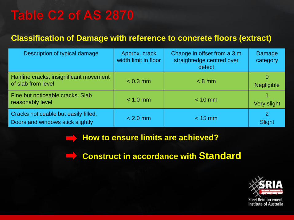
Description of typical damage Approx. crack
width limit in floor
Change in offset from a 3 m
straightedge centred over
defect
Damage
category
Hairline cracks, insignificant movement
of slab from level < 0.3 mm < 8 mm0
Negligible
Fine but noticeable cracks. Slab
reasonably level < 1.0 mm < 10 mm1
Very slight
Cracks noticeable but easily filled.
Doors and windows stick slightly< 2.0 mm < 15 mm
2
Slight
Classification of Damage with reference to concrete floors (extract)
How to ensure limits are achieved?
Construct in accordance with Standard
Not just about placing concrete
All factors must be considered as contributing to performance
Classify site correctly
Select appropriate standard design
Modify if necessary for site conditions eg rock outcrops, pipes
Comply with detailing requirements
Comply with construction requirements

Not just about footing/raft design
Walling must also be considered
Section 3 Standard Designs include details for:
Articulated masonry veneer
Articulated full masonry
Full masonry construction incorporating articulation of external and
internal walls
Masonry veneer construction incorporating articulation of the masonry
veneer.

Typical articulation joints

AS 4773.1 (2010)
Masonry for small buildings
contains requirements
for articulation joints
called up in BCA
contraction joints included
expansion joints included
CCAA TN61
Articulated Walling
www.ccaa.com.au
Referenced in AS 2870

Drainage
Requirements for rafts and slabs
Concrete
Reinforcement
Vapour barriers and damp-proof membranes
Edge rebates
Recesses in slab panels
Heating cables and pipes
Shrinkage cracking control
Beam continuity in rafts
Beam layout restrictions

Requirements for Pad and Strip Footings
Concrete
Reinforcement
Stepping of strip footings
Requirements in Aggressive Soils
Additional requirements for Classes M, H1, H2 and E Sites

Avoid water ponding against or near the footing
Slope ground away from building (50 mm over 1 m width)
Consider effects of a number of variables such as flooding and
landscaping
Avoid water entering the building
For Class 1 buildings, minimum floor height above finished ground or
paving level
150 mm typically
100 mm for sandy, well-drained areas
50 mm where adjacent paving slopes away from building
May be reduced locally (at doorways) if shielded from weather

Drains
Channels
Ponds
Dams
Tanks
Trees
Fill
Urbanisation
Previous structuresPrevious structure has changed
moisture conditions
New
building
Existing building

Heave due
to wettingSettlement due
to drying
Note:
Distortion limit
generally 1:200
Cut and fill

Concrete
N20, 100 mm slump, 20 mm maximum nominal aggregate size
In accordance with AS 1379 – ensures quality, not final performance
Reinforcement – previously covered
Vapour barriers and damp-proof membranes
Materials, properties and installation - only in AS 2870
NSW and SA required to have damp-proof membrane

Shrinkage cracking control
Re-entrant corners – 2 x 3-L8TM, 1 x 3-L11TM or 3-N12
Brittle floor coverings
• Minimum SL92 mesh or extra layer of slab mesh
• Use appropriate bedding system
• Delay placement of brittle finishes
Large tiled areas Polished concrete

Shrinkage cracking control – floor heating
Hydronic floor
heating system
Electric systems – no increase in slab thickness or mesh size
Hydronic systems
• increase slab thickness by 25 mm
• increase mesh by one size

Beam continuity in rafts
Continuity of internal and external beams must be maintained
from edge to edge of the slab
across steps in the slab (Clause 6.4.4 (c) (iii))
at re-entrant corners
• provide internal beam
• if < 1.5 m, refer details in Figure 5.4
Continuity of footing beams
(Figure 5.4 from AS 2870 - 2011)
(dimensions in metres)

Beam continuity in rafts - Commentary
Arrangement of stiffening beams
(Figure C5.4 from AS 2870 - 2011)

Beam spacing at external corners
(Figure 5.5 from AS 2870 - 2011)
Beam layout restrictions
Limits placed on spacing of internal beams at external corners

Beam spacing at corners
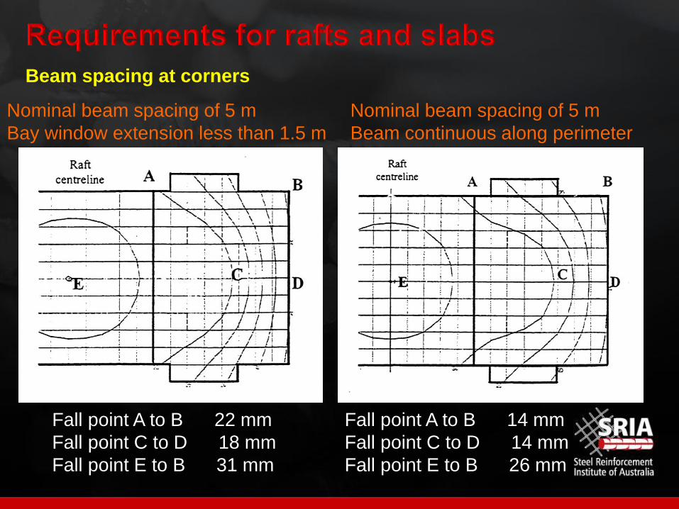
Fall point A to B 22 mm
Fall point C to D 18 mm
Fall point E to B 31 mm
Fall point A to B 14 mm
Fall point C to D 14 mm
Fall point E to B 26 mm
Nominal beam spacing of 5 m
Bay window extension less than 1.5 m
Nominal beam spacing of 5 m
Beam continuous along perimeter
Beam spacing at corners
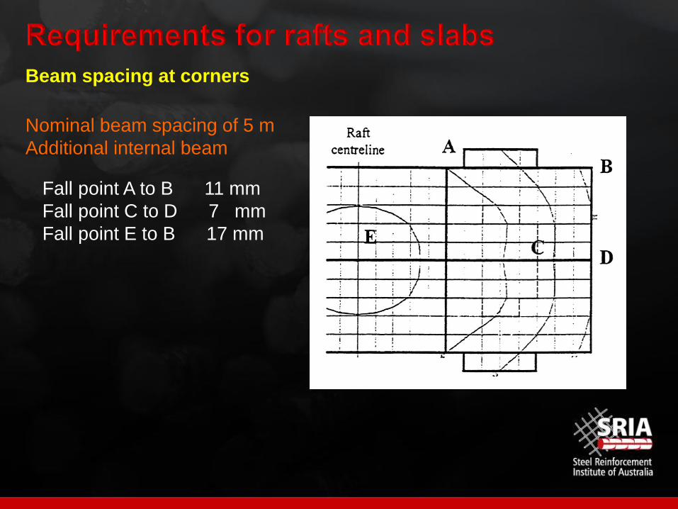
Fall point A to B 11 mm
Fall point C to D 7 mm
Fall point E to B 17 mm
Nominal beam spacing of 5 m
Additional internal beam
Beam spacing at corners

Beam continuity in rafts – maintain stiffness
Arrangement of stiffening beams
(Figure C5.5 from AS 2870 - 2011)

Concrete – as for rafts and slabs
Reinforcement – covered
Stepping of strip footings
Acceptable methods of stepping
strip footings
(Figure 5.6 from AS 2870 - 2011)

Saline and sulphate soils
Western
Sydney
Wagga Wagga
NSW
Efflorescence is more
common sign of soil salinity

Requirements in Aggressive Soils – Clause 5.5
Two choices:
1. Isolate the concrete or masonry member from the aggressive soil
2. Use appropriate concrete strength and cover
Isolation of Concrete
Provide damp-proof membrane up to ground or finished paving level
Extend membrane from under slab up to this point
Lap membrane from under slab with
suitable damp-proofing material (0.5
mm thick) or liquid-applied
waterproofing compound applied to
face of concrete and extend up to
finished ground or paving level.

Extend membrane from under slab up to finished ground or paving level
Figure 5.7 Use of damp-proofing membrane for slab protection
(from AS 2870 - 2011)
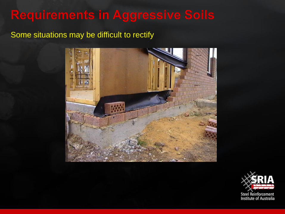
Some situations may be difficult to rectify

Appropriate concrete strength and detailing – Consistent with AS 3600 - 2009
Step 1 Determine appropriate exposure classification for saline soils
Saturated extract
electrical conductivity (ECe),
dS/m
Exposure
classification
<4 A1
4-8 A2
8-16 B1
>16 B2
Exposure classification for concrete in saline
soils (from Table 5.1 of AS 2870-2011)
Courtesy Sydney Environmental & Soil
Laboratories P/L
Measuring salinity

Appropriate concrete strength and detailing
Step 1 Determine appropriate exposure classification for sulfate soils
Exposure conditions Exposure classification
Sulfate (expressed as SO4)
pH
Soil conditions
A
Soil conditions
BIn soil
ppm
In groundwater
ppm
<5000 <1000 > 5.5 A2 A1
5000-10 000 1000-3000 4.5 - 5.5 B1 A2
10 000-20 000 3000-10 000 4 - 4.5 B2 B1
>20 000 >10 000 < 4 C2 B2
Exposure classification for concrete in sulfate soils (after Table 5.2 of AS 2870 - 2011)
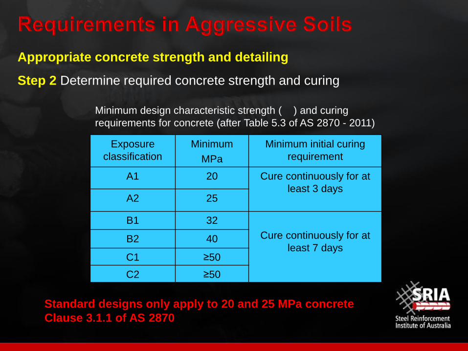
Appropriate concrete strength and detailing
Step 2 Determine required concrete strength and curing
Exposure
classification
Minimum
MPa
Minimum initial curing
requirement
A1 20 Cure continuously for at
least 3 daysA2 25
B1 32
Cure continuously for at
least 7 daysB2 40
C1 ≥50
C2 ≥50
Minimum design characteristic strength ( ) and curing
requirements for concrete (after Table 5.3 of AS 2870 - 2011)
Standard designs only apply to 20 and 25 MPa concrete
Clause 3.1.1 of AS 2870

Appropriate concrete strength and detailing
Step 3 Determine minimum reinforcement cover
Exposure
classification
Minimum cover in saline
soils
(mm)
Minimum cover
in sulfate soils
(mm)
A1 No change 40
A2 45 50
B1 50 60
B2 55 65
C1 Not applicable to salinity 70
C2 Not applicable to salinity 85
Minimum reinforcement cover for concrete (after Table 5.4 of AS 2870 - 2011)

Further Information
1. CCAA Guide to Residential Slabs
and Footings in Saline Environments
www.ccaa.com.au
2. Local Government Salinity Initiative

Excavations
If permanent, retain material or batter sides
If temporary, ensure adequate support of footings is maintained
Construction of slabs
Filling – controlled and rolled
Foundations – Natural soil of 50 kPa bearing capacity for slabs
− Natural soil of 100 kPa bearing capacity for edge
footings not tied to a footing slab
− stepping and sloping of edge beams
− blinding layer of sand only required for aggressive soils
Sloping Sites – details of cut and fill
− stepping of slabs and beams
− where design of pier-and-slab required

Construction of slabs (continued)
Walls retaining fill under slab
Fixing of reinforcement and void formers
Placing, compaction and curing of concrete
The concrete shall be transported, placed, compacted and cured in
accordance with good building practice.
Construction of strip/pad footings – Foundations – 100kPa minimum
Additional requirements for moderately, highly and extremely reactive sites
Penetrations through footings - sleeved
Drainage - water not allowed to pond
Flexible joints in drains - highly and extremely reactive sites
(same as Clause 5.6.4)

Masonry detailing – control joints
Variations in foundation material – part of footing on rock
Drainage requirements – near or under footings
Plumbing requirements – Clause 5.6.4 (b) and 6.6 (e) (i)
Flexible joints to drains
commence within 1 m of the building perimeter
accommodate movement up to ys in any direction
be set at mid-position of their range at time of installation
ie movement range of 0.5 ys from the initial setting

Flexible joints to drains

Concrete to comply with AS 1379 Specification and supply of concrete
Ensures good quality concrete, but not final product
Main quality issues
Addition of excess water
Compaction
Curing
Tolerances
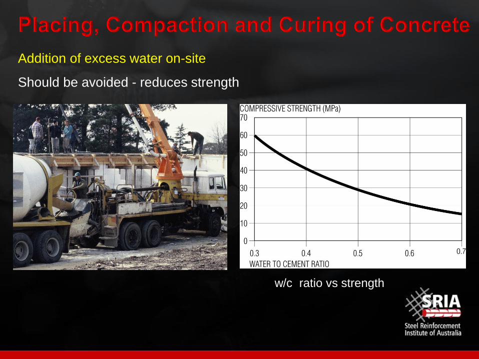
Addition of excess water on-site
Should be avoided - reduces strength
w/c ratio vs strength
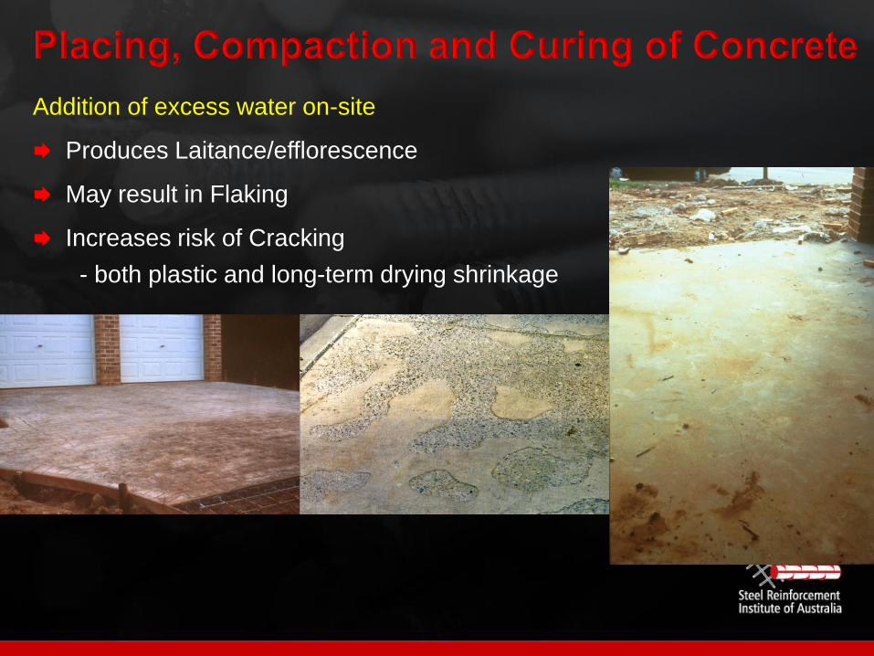
Addition of excess water on-site
Produces Laitance/efflorescence
May result in Flaking
Increases risk of Cracking
- both plastic and long-term drying shrinkage
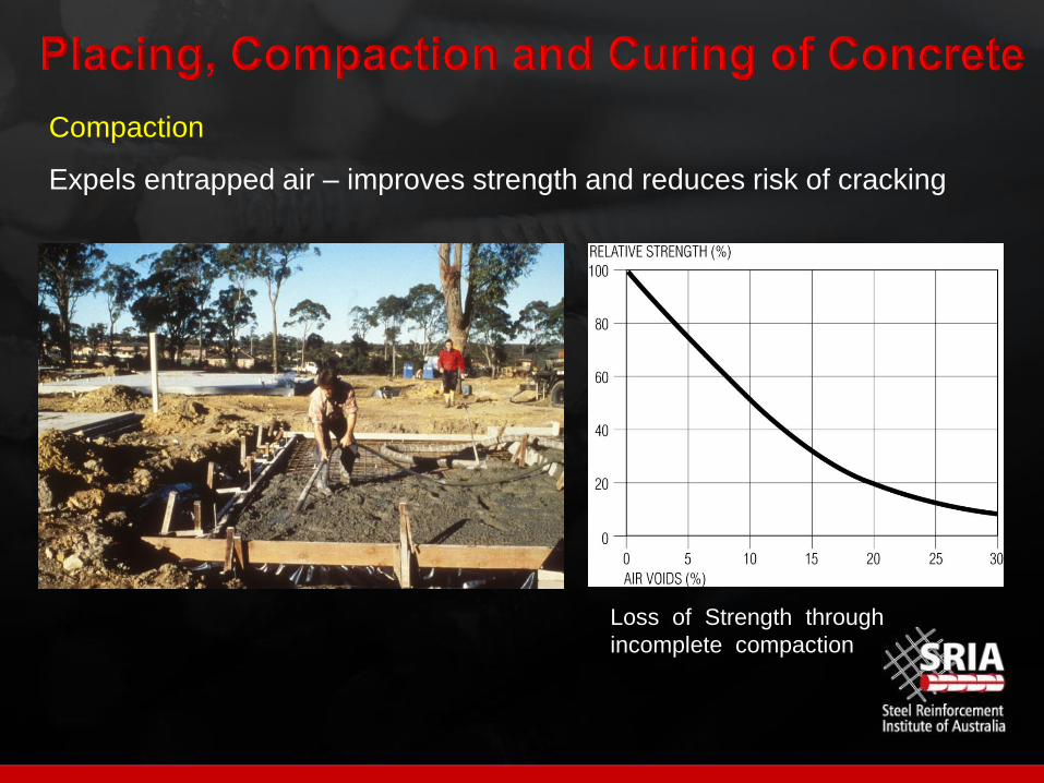
Compaction
Expels entrapped air – improves strength and reduces risk of cracking
Loss of Strength through
incomplete compaction

Compaction
Lack of compaction reduces durability and strength

Curing
Application of water to or retention of water in concrete
Improves strength
Reduces permeability
Reduces risk of cracking and crack widths
Add water to concrete
(must be continuous)
Retain water in concrete

Curing
Important for aggressive soils
Table 5.3 Curing requirements specified
Clause 5.5.3(d) Curing methods detailed
Curing compounds to comply with AS 37990 20 40 60 80 100
Plastic sheeting
Wax based
Chlorinated rubber
Hydrocarbon resin
Water based
Acrylic
PVA
AS 3799 limit
(90% retention)
72 Hour Moisture
Loss (as % of
untreated sample)

Surface Tolerances
Not specified in AS 2870-2011
Guidance given in CCAA Data Sheet
• Measurement
• Standards and specifications
• Specifying tolerances
• Achieving tolerances
• Rectification

Surface Tolerances
Flatness – the deviation of the surface from a straight line joining two
points on the surface
Typically measured using 3-m straightedge for residential work
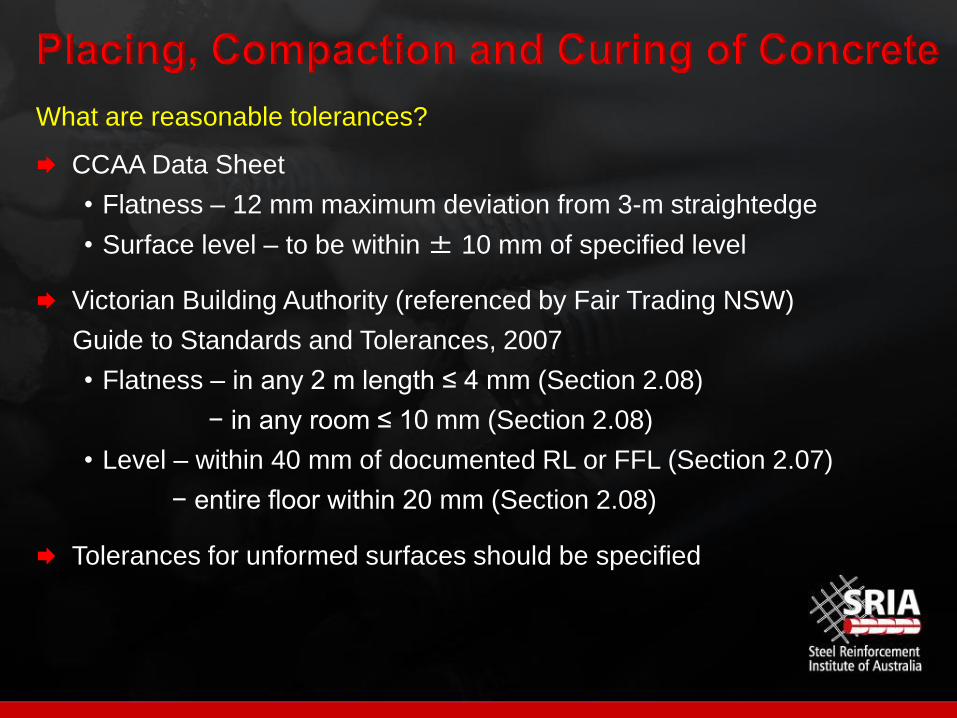
What are reasonable tolerances?
CCAA Data Sheet
• Flatness – 12 mm maximum deviation from 3-m straightedge
• Surface level – to be within ± 10 mm of specified level
Victorian Building Authority (referenced by Fair Trading NSW)
Guide to Standards and Tolerances, 2007
• Flatness – in any 2 m length ≤ 4 mm (Section 2.08)
− in any room ≤ 10 mm (Section 2.08)
• Level – within 40 mm of documented RL or FFL (Section 2.07)
− entire floor within 20 mm (Section 2.08)
Tolerances for unformed surfaces should be specified

Must be set prior to placement of concrete – AS/NZS 2425: 2015

Stiffened raft Filling
Bored piers
or similar
Is mixed construction allowed? eg deepened footings and stiffened raft
For Class M and H sites, only one standard design shall be used (Clause 3.1.1)

Equivalent construction - Table 3.1 of AS 2870
Actual constructionEquivalent construction
External walls Internal walls
Single-leaf masonry
Reinforced single-leaf masonryArticulated masonry on Class A
and Class S sites, or framedArticulated masonry veneer
Reinforced single-leaf masonryArticulated masonry or
reinforced single-leaf masonryMasonry veneer
Reinforced single-leaf masonry Masonry Articulated full masonry
Articulated single-leaf masonry Articulated masonry Articulated full masonry
Articulated single-leaf masonry Masonry Articulated full masonry
Other single-leaf masonry Framed Articulated full masonry
Other single-leaf masonry Masonry Full masonry
Mixed construction
Full masonry Framed Articulated full masonry
Articulated full masonry Framed Masonry veneer
Articulated rendered or sheet clad frame Framed Articulated masonry veneer
Precast concrete panels
Reinforced concrete panel Articulated masonry veneer
Earth wall construction
Infill panels of earth wall construction Articulated masonry veneer
Loadbearing earth wall construction Articulated full masonry

Table 4.1 of AS 2870 - 2011
Span
Differential footing movement,
Footing design must satisfy
both limits in Table 4.1
Type of construction
Maximum differential
deflection, as a function of
span, mm
Maximum differential
deflection, mm
Clad frame L/300 40
Articulated masonry veneer L/400 30
Masonry veneer L/600 20
Articulated full masonry L/800 15
Full masonry L/2000 10
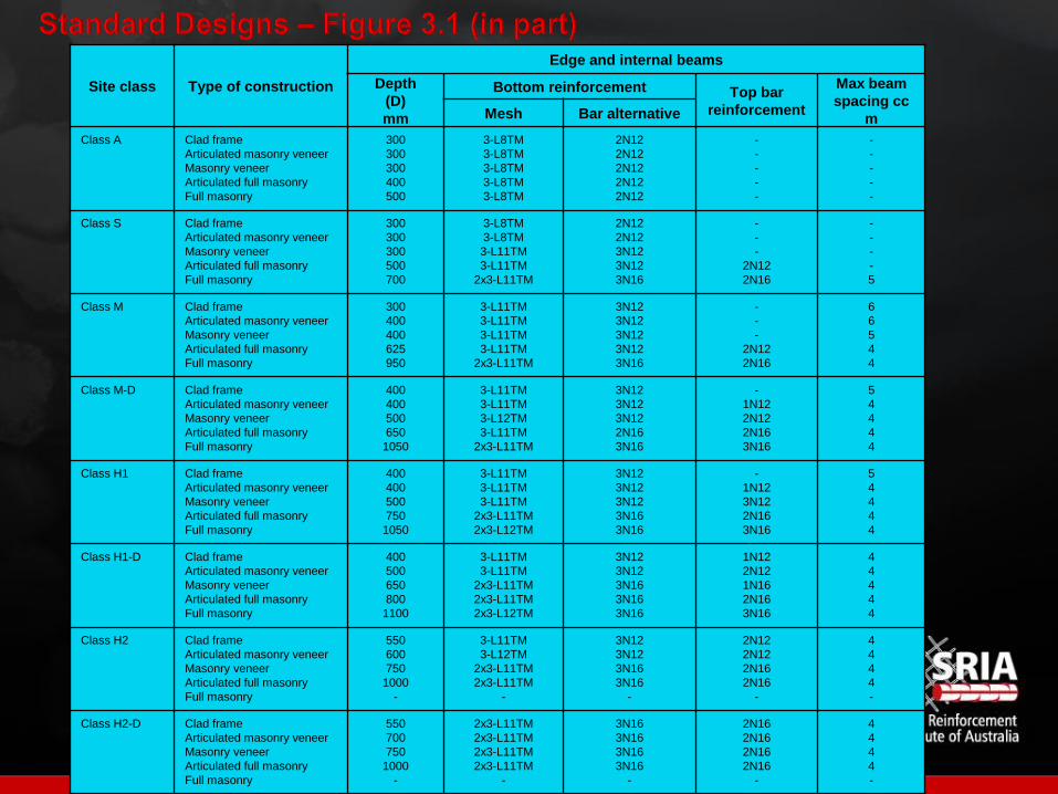
Site class Type of construction
Edge and internal beams
Depth
(D)
mm
Bottom reinforcement Top bar
reinforcement
Max beam
spacing cc
mMesh Bar alternative
Class A Clad frame
Articulated masonry veneer
Masonry veneer
Articulated full masonry
Full masonry
300
300
300
400
500
3-L8TM
3-L8TM
3-L8TM
3-L8TM
3-L8TM
2N12
2N12
2N12
2N12
2N12
-
-
-
-
-
-
-
-
-
-
Class S Clad frame
Articulated masonry veneer
Masonry veneer
Articulated full masonry
Full masonry
300
300
300
500
700
3-L8TM
3-L8TM
3-L11TM
3-L11TM
2x3-L11TM
2N12
2N12
3N12
3N12
3N16
-
-
-
2N12
2N16
-
-
-
-
5
Class M Clad frame
Articulated masonry veneer
Masonry veneer
Articulated full masonry
Full masonry
300
400
400
625
950
3-L11TM
3-L11TM
3-L11TM
3-L11TM
2x3-L11TM
3N12
3N12
3N12
3N12
3N16
-
-
-
2N12
2N16
6
6
5
4
4
Class M-D Clad frame
Articulated masonry veneer
Masonry veneer
Articulated full masonry
Full masonry
400
400
500
650
1050
3-L11TM
3-L11TM
3-L12TM
3-L11TM
2x3-L11TM
3N12
3N12
3N12
2N16
3N16
-
1N12
2N12
2N16
3N16
5
4
4
4
4
Class H1 Clad frame
Articulated masonry veneer
Masonry veneer
Articulated full masonry
Full masonry
400
400
500
750
1050
3-L11TM
3-L11TM
3-L11TM
2x3-L11TM
2x3-L12TM
3N12
3N12
3N12
3N16
3N16
-
1N12
3N12
2N16
3N16
5
4
4
4
4
Class H1-D Clad frame
Articulated masonry veneer
Masonry veneer
Articulated full masonry
Full masonry
400
500
650
800
1100
3-L11TM
3-L11TM
2x3-L11TM
2x3-L11TM
2x3-L12TM
3N12
3N12
3N16
3N16
3N16
1N12
2N12
1N16
2N16
3N16
4
4
4
4
4
Class H2 Clad frame
Articulated masonry veneer
Masonry veneer
Articulated full masonry
Full masonry
550
600
750
1000
-
3-L11TM
3-L12TM
2x3-L11TM
2x3-L11TM
-
3N12
3N12
3N16
3N16
-
2N12
2N12
2N16
2N16
-
4
4
4
4
-
Class H2-D Clad frame
Articulated masonry veneer
Masonry veneer
Articulated full masonry
Full masonry
550
700
750
1000
-
2x3-L11TM
2x3-L11TM
2x3-L11TM
2x3-L11TM
-
3N16
3N16
3N16
3N16
-
2N16
2N16
2N16
2N16
-
4
4
4
4
-

Design Parameter Range
ys
10 mm to 70 mm if Hs > 3 m or
10 mm to 100 mm if Hs < 3 m
∆ 5 mm to 50 mm
Span 5 m to 30 m
Beam spacing
≤ 1.25 values in Figure 3.1
Clause 5.3.9 shall apply at external corners of the building.
For Class E sites the beam spacing shall not exceed 5 m.
Beam depth 250 mm to 1200 mm
Minimum depth of any beam ≥ 0.8 max. beam depth
Beam width 110 mm to 400 mm
Design distributed load ≤ 10 kPa
Design edge line load ≤ 25 kN/m
Design parameters within the following range (Clause 4.5.1)

Site considerations Verandahs
Trussed roofs
Maintenance of drainage
Gardens and watering
Plumbing leaks
Internal wall
Roof
trussesVerandah
Separate
footing