Embed Size (px)
Citation preview

ReservoirEquipment
Global Filtration Technology
07 RESERVOIR EQUIPMENT 28/6/02 3:57 pm Page 191

TECHNICAL DATA
Reservoir EquipmentEAB Series
APPLICATIONS
Typical Applications
Agricultural Machines
Articulated Dump Trucks
Forestry Equipment
Wheeled Loaders
Lubricating Systems
Excavators
Mobile Cranes
Industrial Power Units
The breather has been designed to achieve a low pressure dropand high dirt holding capacity with airflow up to 1500 l/min.
Construction:Glass reinforced composite housing with Eco-element.
Filter Media Options:P020: High quality polyester media. Degree of filtration 2µm (abs).C015: Polyester media with water-resistant layer. Degree offiltration 1.5µm (abs)Q010: Glass fibre media. Degree of filtration 1.0µm (abs)
Mounting Options:With 6 screws. Includes machine and plate screws, a strainer andgaskets.External threads G3/4”, G1” abd M33x2.Internal thread G3/4”.
Options:Visual gauge type vacuum/pressure indicator.Overpressure valve, pressure setting 0.2 bar.
Advantages of the new EAB20:Easy maintenance.Indicator states the need for element change.Quick and easy element change with no tools.
Environmentally Friendly:EAB20 element contains no metal parts: therefore it can becrushed and burned minimising the volume of waste material.
Other Features:
The optional indicator is located in a safe place inside the housing.Housing includes mounting holes for a padlock, which allows youto increase the security against theft and vandalism.
PRESSURE DROP CURVES
Housing (Without Element)∆p total = ∆p housing + ∆p element. The recommended level of the initial pressure drop for this filter is max 0.02 bar (2.0 kPa).
Q (dm3/min)
∆p (
kPa)
GE12
5.0
0.0
1.0
2.0
3.0
4.0
1.5
2.5
3.5
4.5
0.5
0 200018001600140012001000800600400200
GS12GE16ME33
EAC20 P020
Q (dm3/min)
∆p (
kPa)
3.0
0.0
1.0
2.0
1.5
2.5
0.5
0 200018001600140012001000800600400200
IN>OUT
OUT>IN
EAC20 C015
Q (dm3/min)
∆p (
kPa)
3.0
0.0
1.0
2.0
1.5
2.5
0.5
0 200018001600140012001000800600400200
IN>OUT
OUT>IN
EAC20 Q010
Q (dm3/min)
∆p (
kPa)
3.0
0.0
1.0
2.0
1.5
2.5
0.5
0 200018001600140012001000800600400200
IN>OUT
OUT>IN
192
07 RESERVOIR EQUIPMENT 28/6/02 3:57 pm Page 192

Reservoir EquipmentEAB Series
EAB
6 HOLE FIXING MOUNTING DIMENSIONS
SPECIFICATION
ORDERING EXAMPLE ELEMENTTable 1 Table 2 Table 3 Table 4
Table 1
CODE
V2No overpressure valveOverpressure valve setting 0.2 bar
CODEP020C015Q010
Polyester media 2.0 microns absoluteWater-resistant media 1.5 microns absoluteGlass fibre media 1.0 microns absolute
Overpressure Valve OptionsFiltration Media & Degree of Filtration
Table 1 Table 3
Standard 6 holes arranged with diam. 73mmExternal thread G3/4”External thread G1”Internal thread G3/4”External thread M33x2
CODEHC73GE12GE16GS12ME33
Mounting Options
Table 2
No indicatorVacuum/Pressure gauge
CODE
A
Indicators Options
Table 4
Complete Filter:
Replacement Element:
EAB20
EAC20
OPTIONAL INDICATOR
HOLES FOR LOCKING
OPTIONAL MOUNTING BY 6 SCREWS
These holes are always open providingdrainage of splash water
114(4.49)
AIR FLOWQ = 1500 l/min
max
102
(4.0
2)
43(1
.69)
Ø90(3.54)
Ø73(2.87)
G1
M33x2
G3/4
G3/4
OPTIONAL MOUNTING
mm(inches)
NOTICE!Breather is an essentialpart of the system andthe element needs tobe replaced regularly.
6 x 60° Ø4 or M5
7355
193
07 RESERVOIR EQUIPMENT 28/6/02 3:57 pm Page 193

SPECIFICATION
Reservoir EquipmentABL Series
APPLICATIONS
Typical ApplicationsSaw Mills
Agricultural Machines
Articulated Dump Trucks
Forestry Equipment
Wheeled Loaders
Lubricating Systems
Excavators
Industrial Power Units
Mobile Cranes
The Parker Filtration ABL-1 and ABL-2 Series Air Breathers.
High performance air breathers are often applied when it comes
to optimal protection of hydraulic and lubrication systems from
contamination. The ABL-1 has a flow capacity of 1000 l/min,
the larger ABL-2 is capable of handling 2000 l/min. Both are
equipped with a base plate featuring a BSP port or a UN thread,
and 3-micron replaceable Leif¤ elements. The ABL is equipped
with a reusable cap. The visual indicator of the ABL-2 (optional
for the ABL-1) indicates when the air breather element requires
replacement. An extension mounting adaptor and an adaptor
with filling connection are available as accessories.
Assembly:Tank top mounted
Connections:Threads G11/4 (ISO228), 11/2” (UN-16-2B)
Seal Material:Seals integrated in Leif® element
Operating Temperature Range:-20° to +80°C
Filtration Media:3 micron
Flow Fatigue Characteristics:Filter media is supported so that the optimalfatigue life is achieved
Vacuum Indicator:ABL-1 on request only, ABL-2 0.04 bar.Visual with latch out memory.
Breather Housing:High impact strength composite
Filter Element:Leif® element
Options:Adaptor with filter connectionSingle adaptorBreather with integrated pressure relievevalve for pressurised tank on request only
Leif® elements can be applied for hydraulic fluidsonly. For other fluids contact Parker Filtration.
PRESSURE DROP CURVESPressure Loss Curve ABL1
0
0.5
1
1.5
2
2.5
0 150 300 450 600 750 900 1050 1200 1350 1500
delta-p
Flow (l/min)
∆p (
mb
ar)
0 79 159 238 396
Flow (US GPM)
31736.3
29
21.8
7.3
0
14.5 ∆p (
psi
d)
Pressure Loss Curve ABL2
0
0.5
1
1.5
2
2.5
0 500 1000 1500 2000 2500Flow (l/min)
∆p (
mb
ar)
36.3
29
21.8
7.3
0
14.5 ∆p (
psi
d)
0 132 264 396 660
Flow (US GPM)
528
Ordering CodeABL-1G11/4QXWL-3-
ABL-2G11/4QXWL1-3V
Ordering Code Flow (l/min)10002000
Flow (l/min) Media RatingGDL 03GDL 03
PortsG11/4”G11/4”
Ports Indicator–
Visual
Indicator Replacement ElementsQXWL-3QXWL1-3
Replacement Elements
PREFERRED PRODUCTS TABLE
NOTE: Filters ordered from the Part Number Matrix on the next page are on extended lead times. Where possible, please make yourselection from the table above.
Media Rating
194
07 RESERVOIR EQUIPMENT 28/6/02 3:57 pm Page 194

Reservoir EquipmentABL Series
ABL-1 ABL-2
EXTENSION AND FILLING MOUNTING ADAPTORS
TOP VIEW
TOP VIEW
1
2
3
4
SPECIFICATION
ORDERING EXAMPLE ELEMENT
ORDERING EXAMPLE AIRBREATHER
3
1 2 3 4
ABL1 G11/4 QXWL-3 –
ORDERING EXAMPLE ADAPTORStd 2 5
ADAPTOR ABL G11/4 FP
Std 2 5
ADAPTOR ABL G11/4 SNG1 2 3 4
ABL2 G11/4 QXWL1-3 V
QXWL1-3
Element
ABL-1ABL-2
3µmCODE
QXWL-3QXWL1-3
CODEABL-1ABL-2
Housing1000 l/min2000 l/min
Degree of FiltrationBreather Type
Table 1 Table 3
PortsISO 228-G11/4 (BSP)11/2” UN-16-2B
CODEG11/4
U11/2
Breather Connection
Table 2
IndicatorNo indicatorVisual
CODE–V
Indicators
Table 4
AdaptorSingleWith filler connection
CODESNGFP
Options
Table 5
(35.
5)10
5
25
15 (N
OIN
DIC
ATO
R)
ISO228-G11/4OPTIONAL: 11/2-16UN-2B
46 A/F
Ø12711/2-16UN-2B
(Optional: ISO228-G11/4)SLW46
Ø127
1
2
3
35.5
163
25
Ø85
2
80
A
6xØ7(PCDØ73)
A
6xØ7(PCDØ73)
2
Ø85
400
9545
1 /2”
BS
P
ADAPTOR SINGLE ADAPTOR WITH FILLER CONNECTION
NOTICE!Breather is an
essential part of thesystem and the
element needs to bereplaced regularly.
195
07 RESERVOIR EQUIPMENT 28/6/02 3:57 pm Page 195

Reservoir EquipmentIP65 Rated Filler Breather Filters
SPECIFICATION FOR SINGLE AND 6 HOLE INSTALLATION
OPTION 1 FILLER BREATHERS (SINGLE HOLE INSTALLATION)
Option 1Construction:Moulded in non-corrodibleglass-filled nylon combiningstrength with a lightweightdesign.Options:(1) Single (63mm Dia) HoleFiller Breather installation thateliminates drilled and tappedholes using self-locking clamps.(2) 6 HoleFiller Breather Installation thatuses 6 x No 10 threadforming screws.(3) 3 Hole Filler Breatheroption is available Self-Locking Clamps (SingleHole Option):3 x Zinc and clear chromateplated steel screws.Spring steelclamps.
Strainers:Unique design diffuses oilflow into the reservoir.(1) Single length inPolypropylene (95mm length)(2) 2-piece telescopic inPolypropylene (195mm lengthmax.)Filtration Element:Expanded Polyurethane foam,10 micron.Seals:Nitrile.Working Temperature:-30°C to +90°C.Pressurised FillerBreathers:Available in 3 pressure options toreduce the risk of contamination.Pressurisation Options:0.2, 0.35 and 0.7 bar crackpressure.
Pressurisation Value:Nylon/Nitrile.Dipstick:Available for use with options1 and 2. Dipsticks areavailable in 2 lengths and inpacks of 10.Dipstick Material:ABS.Hi/Lo Indicators:Acetal. Adjustable Red/Greenlevel indicators.Dipstick Lengths:200mm and 400mm.Breather Weight:0.2Kg.Anti-Splash Feature:The unique design anti-splashfeature is standard on allOptions 1 and 2 and allowsfor a dipstick to be fitted ifrequired.
∆p (
bar
)
0 5 10 15Flow I/sec (Air)
1.0 0.2 Valve
0.2 Valve
0.2 Valve
1.2
0.8
0.6
0.4
0.2
0
16.9
14.6
11.6
2.9
0
5.8 ∆p (
psi
d)
7.3
0 5 10 15Flow I/sec (Air)
∆p (
bar
)
Without Anti-Splash
With Anti-Splash
0.20
0.15
0.10
0.05
0
0.25
2.9
0
1.5 ∆p (
psi
d)
Ø101
Ø42
7010
MA
X
167
Ø7.0
A
A
10 micron pressurised.0.2 bar without strainer
10 micron pressurised.0.2 bar with 95mm strainer
10 micron pressurised.0.2 bar with telescopic strainer
10 micron pressurised.0.35 bar without strainer
10 micron pressurised.0.35 bar with 95mm strainer
10 micron pressurised.0.35 bar with telescopic strainer
10 micron pressurised.0.7 bar without strainer
10 micron pressurised.0.7 bar with 95mm strainer
10 micron pressurised.0.7 bar with telescopic strainer
AB.98212001.UCAB.98212011.UCAB.98212021.UCAB.98213001.UCAB.98213011.UCAB.98213021.UCAB.98217001.UCAB.98217011.UCAB.98217021.UC
FBI.A1B1A2PFBI.A1B1B2PFBI.A1B1C2PFBI.A1C1A2PFBI.A1C1B2PFBI.A1C1C2PFBI.A1D1A2PFBI.A1D1B2PFBI.A1D1C2P
10 micron filler breather without strainer10 micron filler breather with 95mm strainer10 micron filler breather with telescopic strainer
AB.98210001.UCAB.98210011.UCAB.98210021.UC
FBI.A1A1A2PFBI.A1A1B2PFBI.A1A1C2P
Option 1. Single Hole Filler Breathers – non-pressurisedPart Number Supersedes Description
Option 1. Single Hole Filler Breathers – pressurisedPart Number Supersedes Description
AB.98XXX Pressurised Pressure Drop Curves
AB.98XXX Non-Pressurised Pressure Drop Curves
196
07 RESERVOIR EQUIPMENT 28/6/02 3:57 pm Page 196

Reservoir EquipmentIP65 Rated Filler Breather Filters
FILLER BREATHERS (6 HOLE INSTALLATION)
Option 2
Note 1. Un-pressurised 6 hole fixing:Form 6 off tank mounting holes between Ø4.0 and 4.4mm (dependent on the material and thickness – see guide below)equispaced on 70-73mm P.C.D. to suit No.10 thread forming screws supplied.
Note 2. Pressurised 6-hole fixing:Form 6 off tank mounting holes between Ø4.0 and Ø4.4mm (dependent on the material and thickness – see guide below)equispaced on 73mm P.C.D. to suit No.10 thread forming screws supplied.
Note 3. Reservoir mounting guide
Sheet thickness mm Hole size mm1.2 4.02.0 4.103.15 4.304.0 4.305.0 4.40
10 micron pressurised. 0.2 bar without strainer
10 micron pressurised. 0.2 bar with 95mm strainer
10 micron pressurised. 0.2 bar with telescopic strainer
10 micron pressurised. 0.35 bar without strainer
10 micron pressurised. 0.35 bar with 95mm strainer
10 micron pressurised. 0.35 bar with telescopic strainer
10 micron pressurised. 0.7 bar without strainer
10 micron pressurised. 0.7 bar with 95mm strainer
10 micron pressurised. 0.7 bar with telescopic strainer
AB.98812001.UCAB.98812011.UCAB.98812021.UCAB.98813001.UCAB.98813011.UCAB.98813021.UCAB.98817001.UCAB.98817011.UCAB.98817021.UC
FBI.D1B1A2PFBI.D1B1B2PFBI.D1B1C2PFBI.D1C1A2PFBI.D1C1B2PFBI.D1C1C2PFBI.D1D1A2PFBI.D1D1B2PFBI.D1D1C2P
10 micron filler breather without strainer10 micron filler breather with 95mm strainer10 micron filler breather with telescopic strainer
AB.98810001.UCAB.98810011.UCAB.98810021.UC
FBI.D1A1A2PFBI.D1A1B2PFBI.D1A1C2P
Option 2. 6-hole filler breathers – non-pressurisedPart Number Supersedes Description
Option 2. 6-hole filler breathers – pressurisedPart Number Supersedes Description
Telescopic StrainerThe telescopic strainer design isideal, where reservoir depthallows, to increase the surfacearea of the strainer, improvingstill further its straining abilityand oil flow-through andallowing for longer dipsticklengths.
Ø101
Ø42
167
72
Ø101
Ø42
271
72
A 73 70
6x Ø4.44.0
Ø31
197
07 RESERVOIR EQUIPMENT 28/6/02 3:57 pm Page 197

Reservoir EquipmentFiller Breather Filters
OPTION 3 FILLER BREATHERS (3 HOLE INSTALLATION)
DIPSTICK OPTIONS
Note: Form 3 off tank mounting holes between Ø4.0 andØ4.4mm (dependent on the material and thickness – see chartfor guide) equispaced on 41.3 P.C.D. to suit No. 10 threadforming screws supplied.
4663
.5
Ø24
Ø50
.5
Ø53
A 41.3
3x Ø4.44.0
Part Number Supersedes Description
Part Number Description10 micron filler breather without strainer10 micron filler breather with 95mm strainer
AB.68110AB.68118
1 Pack 10 x 200mm dipsticks1 Pack 10 x 400mm dipsticks
DIP.206DIP.207
DIP.FB2DIPFB4
Dipstick ordering
3-hole Filler Breathers (6-hole available)
Note: Not suitable for use with DIP.206/207 6-hole AB.68910/AB.68918 available.
DipsticksThe dipstick, available in 2 lengths – 200mm and 400mm, canbe cut to the required length or left as it is and the Hi/Loindicators moved and positioned on the dipstick itself bysqueezing the sides of the indicator and repositioning alongthe dipstick.
New Options Fully TestedAs part of the design development programmefor the new IP65 Filler Breathers, extensiveperformance and endurance testing was carriedout to ensure durability and efficiency.
198
07 RESERVOIR EQUIPMENT 28/6/02 3:57 pm Page 198

Reservoir EquipmentScrew-On Type Air Breathers
STANDARD SCREW-ON BREATHERS — SPECIFICATION
Option 1– G1/2 and G3/4 (Ø101)
PRESSURE DROP FLOW CURVES
10 micron G1/2 option 1 un-pressurised10 micron G1/2 option 1 pressurised 0.2 bar10 micron G1/2 option 1 pressurised 0.35 bar10 micron G1/2 option 1 pressurised 0.7 bar10 micron G3/4 option 1 un-pressurised10 micron G3/4 option 1 pressurised 0.2 bar10 micron G3/4 option 1 pressurised 0.35 bar10 micron G3/4 option 1 pressurised 0.7 bar1 pack 10 x 200mm dipsticks1 pack 10 x 400mm dipsticks
AB.98610101.UCAB.98612101.UCAB.98613101.UCAB.98617101.UCAB.98410101.UCAB.98412101.UCAB.98413101.UCAB.98417101.UCDIP.206DIP.207
FBI.C1A2A2PFBI.C1B2A2PFBI.C1C2A2PFBI.C1D2A2PFBI.B1A2A2PFBI.B1B2A2PFBI.B1C2A2PFBI.B1D2A2PDIP.FB2DIP.FB4
Part Number Supersedes Description
Option 1 – G1/2 or G3/4
0 5 10 15Flow I/sec (Air)
∆p (
bar
)
0
0.30
0.25
0.20
0.15
0.10
0.05Without Anti-Splash
With Anti-Splash
4.4
1.5
0
2.9
∆p (
psi
d)
Note: For pressure drop information on the Option 1. Pressurised consult Parker Filtration.
AB.98XXX Screw-on Non-Pressurised Pressure Drop Curves
G1/2
G3/4
Ø101
Ø101
G1/2
G3/4
30 A/F HEX
93
1310
96
1610
A
A
30 A/F HEX
199
Construction:Moulded in non-corrodible glass-fillednylon combining strength with alightweight design.
Option 1:2 screw on type air breathers are available– G1/2 or G3/4 threaded base models.
Filtration Element:Expanded Polyurethane foam, 10 micron.
Seals:Nitrile.
Working Temperature:-30°C to +90°C.
Pressurised Air Breathers:Available in 3 pressure options toreduce the risk of contamination.
Pressurisation Options:0.2, 0.35 and 0.7 bar crack pressure.
Pressurisation Value:Nylon/Nitrile.
Dipstick:Available for use with all options.Dipsticks are available in 2 lengths andin packs of 10.
Dipstick Material:ABS.
Hi/Lo Indicators:Acetal. Adjustable red/green level indicators.
Dipstick Lengths:200mm and 400mm.
Breather Weight:0.2Kg.
Anti-Splash Feature:The unique design anti-splash feature isstandard on Option 1 and allows for adipstick to be fitted if required.
07 RESERVOIR EQUIPMENT 28/6/02 3:57 pm Page 199

Option 2 – G1/4, G3/8, R1/2 and R3/4 (Ø40)
Construction:G1/4, G3/8, R1/2 and R3/4 cap and base plate mouldings in nylon66.
Element:Expanded Polyurethane foam, 10 micron.
Pressurised Air Breathers:Available G3/8.
Pressurisation Options:0.2, 0.35 and 0.7 bar crack pressure.
Pressurisation Valve:Nylon.
Dipstick:Available for use with R1/2 and R3/4.
Dipstick Material:ABS: G1/4, G3/8 and mini-series in brass.Brass: Mini Series.
Hi/Lo Indicators:Acetal adjustable red/green level indicators.
Dipstick Lengths:200mm and 400mm (packs of 10).
Breather Weights:0.028Kg (G1/4, G3/8, R1/2, R3/4)
Reservoir EquipmentScrew-On Type Air Breathers
COMPACT SCREW-ON BREATHERS — SPECIFICATION
PRESSURE DROP FLOW CURVES
10 micron G1/4 option 2 screw-on10 micron G3/8 option 2 screw-on10 micron R1/2 option 2 screw-on10 micron R3/4 option 2 screw-on
AB.683101.UCAB.68X101.UCAB.68Y101.UCAB.68Z101.UC
SBI.A1A1PSBI.B1A1PSBI.C1A1PSBI.D1A1P
Option 2 – G1/4, G3/8, R1/2 and R3/4
Part Number Supersedes Description
Flow I/sec (Air)
0.20
0 0.5
∆p (
bar
)
0.18
0.16
0.14
0.12
0.10
0.08
0.06
0.04
0.02
01.0 1.5 2.0 2.5 3.0 3.5 4.0 4.5
G1/4219
115
0
∆p (
psi
d)
Note: For pressure drop information on G3/8, R1/2 and R3/4, consult Parker Filtration.
Ø40
Ø40
Ø40
Ø40
5760 60
59
6
912
.5
1413
.59
G1/4
R1/2
20 A/F HEX
20 A/F HEX
20 A/F HEX G3/8
R3/4
20 A/F HEX
914
G1/4 G3/8
R1/2 R3/4
Note: Only available in multiples of 10
200
07 RESERVOIR EQUIPMENT 28/6/02 3:57 pm Page 200

Reservoir EquipmentScrew-On Type Air Breathers
SCREW-ON TYPE AIR BREATHERS — SPECIFICATION
Option 3 – G3/8, G1/2 and G3/4 (Ø70)
Construction:Mouldings in glass-filled nylon and glass coupledpolypropylene.
Element:Expanded Polyurethane foam, 10 micron.
Seals:Nitrile.
Pressurised Air Breathers:Available G3/8, G1/2 and G3/4,3 pressure options to reduce the risk of contamination.
Pressurisation Options:0.2, 0.35 and 0.7 bar crack pressure.
Pressurisation Valve:Nylon.
Dipstick:Available for use with G3/8, G1/2 and G3/4.
Dipstick Material:Mini-series in brass.
Hi/Lo Indicators:Acetal adjustable red/green level indicators.
Dipstick Lengths:200mm and 400mm (packs of 10).
Breather Weights:0.075Kg, Mini-series – 0.019Kg.
PRESSURE DROP FLOW CURVES0.14
0.12
0.10
0.08
0.06
0.04
0.02
0 5 10 15 20 25Flow I/sec (Air)
∆p (
bar
)
G3/8
G1/2
G3/4
0
Note: For pressure drop information on G3/8, consult Parker Filtration.
10 micron G3/8 non-pressurised screw-on type10 micron G1/2 non-pressurised screw-on type10 micron G3/4 non-pressurised screw-on type
SAB.5101SAB.6101SAB.7101
Option 3 – G3/8, G1/2 and G3/4
Part Number Description
Note: Pressurised versions of G3/8, G1/2 and G3/4 models are available. ConsultParker Filtration.
Pack of 10 x 200mm dipsticksPack of 10 x 400mm dipsticks
DIP.206DIP.207
DIP.FB2DIP.FB4
Dipstick OrderingPart Number Supersedes Description
G3/8 G1/2
G3/4
Ø70 Ø70
Ø70
68 68
71
G3/8 G1/2
G3/4
8.5
8.5
12.5
8.5
12.5
15.5
28 A/F HEX 28 A/F HEX
31 A/F HEX
A
A
THE MINI-SERIES BREATHER
Screw-on option Push-fit option
S.680003 Gearbox air breather
Part Number Description
Ø20
36
20
15°30°
1.6
Ø13.55Ø13.35
Ø22 SPOTFACE
7.8
10.5 MIN
Ø16.2516.00
Ø15.1015.00
Ø11.8G1/4
201
07 RESERVOIR EQUIPMENT 28/6/02 3:57 pm Page 201
Reservoir EquipmentFiller Breather Filters (Metal)
720720430430
40401010
0.75m3/min0.75m3/min0.45m3/min0.45m3/min
G3/4
G3/4
G3/4
G3/4
0.20 Kg0.20 Kg0.20 Kg0.20 Kg
*SPA.1731.40.5**SPA.1731.40.10*SPA.1731.10.5**SPA.1731.10.10
MBI.B2C2A1PMBI.B2D2A1PMBI.B1C2A1PMBI.B1D2A1P
H00602-004–
H00602-002–
Part Number Supersedes Displacement Rating Air Flow Thread Weightl/min Micron
720720430430
40401010
0.75m3/min0.75m3/min0.45m3/min0.45m3/min
– –– –– –– –
0.27 Kg0.27 Kg0.27 Kg0.27 Kg
MBI.D2C1B1PMBI.D2D1B1PMBI.D1C1B1PMBI.D1D1B1P
H00153-004–
H00153-002–
*CAP.1730.40.5**CAP.1730.40.10**CAP.1730.40.5**CAP.1730.10.10
CPI.D2C1A1PCPI.D2D1A1PCPI.D1C1A1PCPI.D1D1A1P
*PAB.1730.40.5**PAB.1730.40.10*PAB.1730.10.5
**PAB.1730.10.10
Part Number Part Number Displacement Rating Air Flow Thread WeightTotal Assembly Supersedes Cap Assembly Supersedes l/min Micron
720430270135––
40104010––
0.75m3/min0.45m3/min0.30m3/min0.15m3/min
––
– –– –– –– –
––
0.24 Kg0.24 Kg0.07 Kg0.08 Kg
––
MBI.D2A1B1PMBI.D1A1B1PMBI.A2A1B1PMBI.A1A1B1PMBI.D1A1B2PMBI.D2A1B2P
H00153-003H00153-001
––––
CAP.1163.40CAP.1163.10CAP.1380.40CAP.1380.10
––
CPI.D2A1A1PCPI.D1A1A1PCPI.A2A1A1PCPI.A1A1A1P
––
AB.1163.40AB.1163.10AB.1380.40AB.1380.10
55615515
Part Number Part Number Displacement Rating Air Flow Thread WeightTotal Assembly Supersedes Cap Assembly Supersedes l/min Micron
720430270135720
4010401040
0.75m3/min0.45m3/min0.30m3/min0.15m3/min0.75m3/min
G3/4
G3/4
G1/4
G1/4
–
0.20 Kg0.20 Kg0.06 Kg0.06 Kg0.13 Kg
SAB.1562.40SAB.1562.10SAB.1563.40SAB.1563.10AB.1381.40
MBI.B2A2A1PMBI.B1A2A1PMBI.C2A2A1PMBI.C1A2A1PMBI.E2A1A1P
H00602-003H00602-001
–––
Part Number Supersedes Displacement Rating Air Flow Thread Weightl/min Micron
Filler Breather – Filter flange type
Air Breather – Threaded and push-on typeNote: Zinc and yellow passivated caps available. Consult Parker Filtration.
Air Breather – Threaded type (Pressurised)
* Valve Crack Pressure 0.35 bar. **Valve Crack Pressure 0.70 bar. For dipstick and locking lug options consult Parker Filtration.
Filler Breather – Filter type (Pressurised)
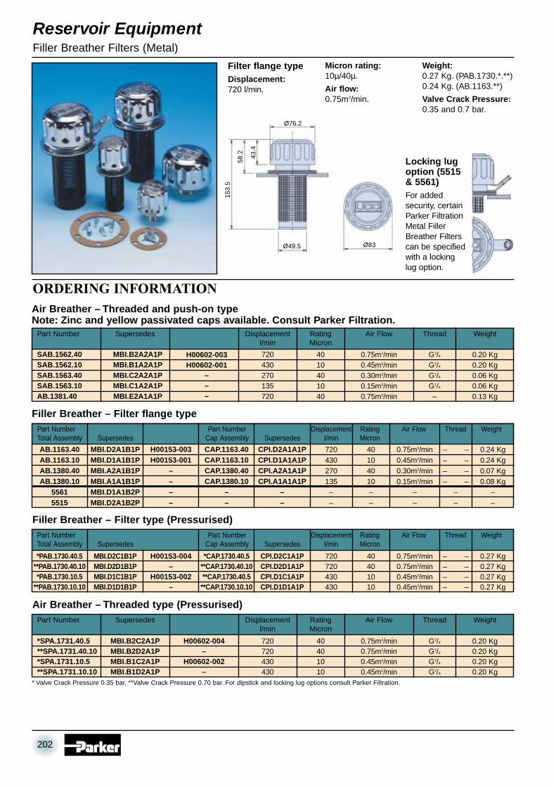
Filter flange typeDisplacement:720 l/min.
Micron rating:10µ/40µ.
Air flow:0.75m3/min.
Weight:0.27 Kg. (PAB.1730.*.**)0.24 Kg. (AB.1163.**)
Valve Crack Pressure:0.35 and 0.7 bar.
Locking lugoption (5515& 5561)For addedsecurity, certainParker FiltrationMetal FillerBreather Filterscan be specifiedwith a lockinglug option.
Ø83
Ø76.2
43.4
58.2
153.
5
Ø49.5
ORDERING INFORMATION
202
07 RESERVOIR EQUIPMENT 28/6/02 3:57 pm Page 202

Reservoir EquipmentFiller Breather Filters (Metal)
Threaded type (Pressurised)
Displacement:720 l/min.
Micron Rating:10µ/40µ.
Air Flow:0.75m3/min.
Weight:0.2 Kg.
Thread:G3/4.
Valve Crack-Pressure:0.35 and0.7 bar.
Displacement:270 l/min.
Micron rating:10µ/40µ.
Air flow:0.3m3/min.
Weight:0.06 Kg.
Thread:G1/4.
Threaded type
Displacement:720 l/min.
Micron rating:40µ.
Air flow:0.75m3/min.
Weight:0.13 Kg.
Push on type
Displacement:270 l/min.Micron rating:10µ/40µ.
Air flow:0.3m3/min.Weight:0.07 Kg.
Filter flange type
TANK INSTALLATION NOTES1. Un-pressurised 6 hole fixingForm off tank mounting holes betweenØ4.0 and Ø4.4 (dependant on the materialand thickness, consult Parker Filtration)equispaced on 70.0-73.0 P.C.D. to suit No.10 thread forming screws supplied.
2. Pressurised 6 hole fixingForm 6 off mounting holes betweenØ4.0 and Ø4.4 equispaced on 73.0P.C.D. to suitNo. 10 thread forming screws supplied.
3. Un-pressurised 3 hole fixingForm 3 off tank mounting holes betweenØ4.0 and Ø4.4 equispaced on 41.3P.C.D. to suitNo. 10 thread forming screws supplied.
35 A/F HEX
16 A/F HEX
RETAININGSPRING CLIP
Ø76.2
G3/4
G1/4
65
16
43.4
6Ø44.5
56.5
13
36.5
7
Ø76.2
43.4
Ø38.1
Ø44.5
36.5
110
47
Ø51
Small breather 1/4” BSPT thread
Small breather 3/8” BSPT thread
Small breather 1/2” BSPT thread
H00279-001
H00279-002
H00279-003
Part Number Description
ORDERING INFORMATION
Ø35
22
5
THREE SIZE:1/4” BSPT3/8” BSPT1/2” BSPT
BREATHER UNITSSmall BreatherSpecification
203
07 RESERVOIR EQUIPMENT 28/6/02 3:57 pm Page 203

Reservoir EquipmentSpin-On Air Breathers
1700 l/min3000 l/min
3/4
11/4
3036
135180
147198
97134
H00834-004H00834-005
Part Number Air Flow Rate DimensionsA B C D E
High capacity air filters designed for the removal of airbornecontamination in hydraulic systems to support environmentalmaintenance.
Ideal for high flow systems and heavily contaminated environments.
Disposable spin-on elements quickly and easily replaced.
3 micron quality filtration elements.
Models available – 1700 l/min and 3000 l/min.
Large Breather Dimensions
SPECIFICATION
1700 l/min3000 l/min3000 l/min
H00834-006H00834-007H00834-007
97134134
165204204
114114203
H00834-001H00834-002H00834-003
Part Air Flow Dimensions Replacement breather canistersNumber Rate A B C including bayonet for
Large Breather Filler Dimensions
ORDERING INFORMATION
MOUNTING FACE FOR STANDARD AND LARGE BREATHER
Maximum Operating Temperature:-20°C to +90°CConstruction Materials:Epoxy coated steel components to resist corrosion. Resistantpaint finish on large BreathersFluid Compatibility:Suitable for use with mineral oils and water oil emulsions
Weights:Large: H00834-001 1.0 Kg Small: 0.12g
H00834-002 1.65 KgH00834-003 1.90 Kg
Each breather filler is supplied with mounting gaskets andself-tapping screws.
73 PCD Ø57 HOLE IN TANK
6 FITTING HOLESØ5.6 EQUISPACEDON PCD
Ø88 BOSS OR SPOT FACE(1.6 MICRON SURFACE FINISH)
ØA
B C
D
E BSPT
ØA
B
C
Ø48
LARGE BREATHER FILLER
STRAINER 30 MESH(600 MICRONS)
204
07 RESERVOIR EQUIPMENT 28/6/02 3:57 pm Page 204

120208
60148
49305884.10
0.6 Kg0.75 Kg
49304930
5884.105884.10
6060148148
120120208208
0.69 Kg0.69 Kg0.8 Kg0.8 Kg
700 l/min700 l/min1500 l/min1500 l/min
*S.340058**S.340059* S.340054**S.340055
A B ReplacementPart Number Air Flow Rate mm mm Weight Element
700 l/min1500 l/min
S.340056S.340052
A B ReplacementPart Number Air Flow Rate mm mm Weight Element
High capacity air filters designed for the removal of airbornecontamination in hydraulic systems to support environmentalmaintenance.
Ideal for high flow systems and heavily contaminated environments.
Disposable spin-on elements quickly and easily replaced.
5 micron quality filtration elements.
2 models available – 700 l/min and 1500 l/min.
Available with a pressurised valve in the mounting adaptor.
Note: Spin-on Air Breather Elementscan also be mounted directly on toany suitable length of 3/4" BSPthreaded pipe.
5 micron Spin-on Air Breathers
Pressurised 5 micron Spin-on Air Breathers Note: The reservoir must be capable of withstanding pressurisation.
* Valve Crack Pressure 0.35 bar. ** Valve Crack Pressure 0.70 bar.
Reservoir EquipmentAir Breathers
ORDERING INFORMATION
CIRCUIT SYMBOL(STANDARD)
CIRCUIT SYMBOL(PRESSURISED)
Ø94
A
B
60
6
Ø97
A
B
Ø51
Ø63
.5
STANDARD SPIN-ON AIR BREATHER STEM
PRESSURISED SPIN-ON AIR BREATHER STEM
RESERVOIR CUTOUT Ø25 MAXIMUM
RESERVOIR CUTOUT Ø25 MAXIMUM
3 OFF M6 FIXING HOLESEQUISPACED ON 41.3 P.C.D.
3 OFF M6 FIXING HOLESEQUISPACED ON 50 P.C.D.
205
07 RESERVOIR EQUIPMENT 28/6/02 3:57 pm Page 205

Non-breathing (No element) 2” BSP thread with strainerNon-breathing (No element) Clamp mounting with strainer10µ element, G2 thread with strainer10µ element, G21/2 thread with strainer10µ element, clamp mounting with strainer40µ element, G2 thread without strainer40µ element, G2 thread with strainer40µ element, G21/2 thread without strainer40µ element, push on mounting without strainer40µ element, clamp mounting with strainer10µ vented (air in) G2 thread without strainer10µ vented (air in) push on mounting with strainer40µ vented (air in) push on mounting without strainer
LFC.622122LFC.622142LFC.622212LFC.622222LFC.622242LFC.622311LFC.622312LFC.622321LFC.622331LFC.622342LFC.622411LFC.622432LFC.622531
Part Number Description
INSTALLATION DETAILS
ORDERING INFORMATIONFlow (l/min)
∆p (
bar
)
10µ40µ
0 500 1000 1500 20000
0.02
0.04
0.060 132 264 528
Flow (US GPM)
3940.87
0.58
0.29
0
∆p (
psi
d)
Tank Mounting
Stand Pipe Mounting
Total assembly pressure drop flow curve – 10µ and 40µ elementsLOCKABLE FILLER BREATHER SELECTION
Reservoir EquipmentLockable Filler Breathers
Ø51
STRAINER3 OFF EQUISPACED CLAMPS
51.5
150107
Ø 7876
TANK MOUNTING HOLE
107
34
6881
149
X
Y
Z
141
A
B
50.5
FLAP TO PROTECT LOCK
2 LOCKING SCREWS THREADED TYPEAT POSITIONS X AND Y3 LOCKING SCREWS PUSH ON TYPEAT POSITIONS X, Y AND Z
206
07 RESERVOIR EQUIPMENT 28/6/02 3:57 pm Page 206

Size 1. 76mm Centres. M10 Thread
Size 1. 76mm Centres. M12 Thread
Fluid LevelFluid Level/Temp
76mm76mm
M12M12
90°C90°C
0.13 Kg0.13 Kg
FL.113FLT.123
LGI.A1B2PLGI.A2B2P
H00361-001–
Part Number Supersedes Description Centres Thread Max Temp Weight
Fluid LevelFluid Level/Temp
76mm76mm
M10M10
90°C90°C
0.13 Kg0.13 Kg
FL.111FLT.121
LGI.A1A2PLGI.A2A2P
––
Part Number Supersedes Description Centres Thread Max Temp Weight
SPECIFICATION
SIZE 1 INSTALLATION DETAILS
For ‘through hole’ mounting:–Thread–
Hole size M10 M12Preferred 11.0 13.0Maximum 13.0 14.0For tapped holes:Holes to be tapped square to mounting face.Tolerance on hole centres: +0.5
-0.2For welded back nuts:The above details should be combined.
Simple to InstallThe universal fixing is designed for either front or rear fixing. Just twoholes in the tank – threaded for front fixing – and the gauge is readyto install. After positioning the gauge the bolts are simply tightened toprovide a secure seal. There is no fear of leakage with the squaresection seals and the two-point mounting system eliminates problemswith tank distortion. M10 and M12 bolt thread options are available.
Easy to ReadThe high-visibility lens is one-piece for added security and moulded inshatterproof, transparent polyamide for an accurate and clear oil leveland temperature indication. Further gauge protection is provided by aspecially designed shroud moulded in high-impact, black polystyrene.
INSTALLATION DATA
INSTALLATION ANDAPPLICATION INFORMATION
ORDERING INFORMATION
Reservoir EquipmentFluid Level Temperature Gauges
Construction:Lens Transparent polyamide.Lens Base Nylon 66.Shroud High impact polystyrene.
No aluminium content.
Seals:Nitrile.
Maximum working pressure:1 bar.
Working temperature:-30°C to +90°C.
Fluid compatibility:Mineral and petroleum based oils.
Note:A 500mm model with metal shroud finished in black available.
Recommended bolt tightening torque:10 Nm maximum.
Thermometer scale range:30°C to 90°C.
Indicator:Blue alcohol.
Note:1. Locate seals in mounting recess before fitting.
2. After choosing ‘fluid level only’ or ‘with temperature’, selectthe size required by studying the installation details todetermine a part number.
DRIVESLOT
BLACKLINE
REDLINE
43
41.5
3018
110
7617
17A
/F H
EX
18.5 24
207
07 RESERVOIR EQUIPMENT 28/6/02 3:57 pm Page 207

Size 2. 127mm Centres. M10 Thread
Size 2. 127mm Centres. M12 Thread
Size 3. 254mm Centres. M10 Thread
Size 3. 254mm Centres. M12 Thread
Fluid LevelFluid Level/Temp
254mm254mm
M12M12
90°C90°C
0.23 Kg0.23 Kg
FL.313FLT.323
LGI.C1B2PLGI.C2B2P
H00361-007–
Part Number Supersedes Description Centres Thread Max Temp Weight
Fluid LevelFluid Level/Temp
254mm254mm
M10M10
90°C90°C
0.23 Kg0.23 Kg
FL.311FLT.321
LGI.C1A2PLGI.C2A2P
––
Part Number Supersedes Description Centres Thread Max Temp Weight
Fluid LevelFluid Level/Temp
127mm127mm
M12M12
90°C90°C
0.15 Kg0.15 Kg
FL.213FLT.223
LGI.B1B2PLGI.B2B2P
H00361-004–
Part Number Supersedes Description Centres Thread Max Temp Weight
Fluid LevelFluid Level/Temp
127mm127mm
M10M10
90°C90°C
0.15 Kg0.15 Kg
FL.211FLT.221
LGI.B1A2PLGI.B2A2P
––
Part Number Supersedes Description Centres Thread Max Temp Weight
SIZE 3 INSTALLATION DETAILS
ORDERING INFORMATION
ORDERING INFORMATION
SIZE 2 INSTALLATION DETAILS
Reservoir EquipmentFluid Level Temperature Gauges
DRIVE SLOT
BLACK LINE
RED LINE
2418.5
41.5
1712
7
161 A/F
HE
X1774
22
43
DRIVE SLOT
BLACKLINE
REDLINE
2418.5
41.5
1725
428
8
A/F
HE
X17
202
22
43
208
07 RESERVOIR EQUIPMENT 28/6/02 3:57 pm Page 208

G3/4 Diffuser for flows up to 100 l/minG1 Diffuser for flows up to 140 l/minG11/2 Diffuser for flows up to 227 l/minG2 Diffuser for flows up to 454 l/min
120127178242
62868686
46556575
0.270.420.560.69
2210220122022203
DFI.A2APDFI.B4APDFI.B6APDFI.B9AP
––
H00835-004H00835-005
Part Number Supersedes Description Amm Bmm Cmm Weight Kg
ORDERING INFORMATION
Construction:Zintec body.30% glass-filled nylon head.Zintec end cap.Epoxy adhesives.
Flow Range:50 l/min up to 454 l/min.
Mounting Threads:G3/4 up to G2.
The effect of fitting adiffuserNote: When installing a diffuserthe plain area on the outsidemust be facing the pump inlet.
The benefits of specifying a Parker Filtration DiffuserInstalling a Parker Filtration Diffuser in a hydraulic reservoir isa simple operation that can make a big difference to systemefficiency.With its special concentric tubes designed with dischargeholes 180° opposed fluid aeration, foaming and reservoir noiseare reduced and pump life extended by reducing cavitation tothe pump inlet.Diffusers manufactured to customer specifications and othersizes of diffusers are available.
Typical pressure drop at rated flow equals 0.035 bar.
SPECIFICATION
INSTALLATION DETAILS
Reservoir EquipmentDiffusers
MOUNTING THREAD
120° PLAIN AREA
C A
/F H
EX
ØB
A
209
07 RESERVOIR EQUIPMENT 28/6/02 3:57 pm Page 209

ORDERING INFORMATION
R.76115 (oil)
R.76125 (water)
0.5
0.5
125 micron filter, G1 thread, oil125 micron filter, G15/16” – 12 UN – 2B, oil125 micron filter, G1 thread, water125 micron filter, G15/16” – 12 UN – 2B, water
E.IL.1115125G1
Reservoir EquipmentInline Filters
METAL INLINE FILTER — SPECIFICATION
ORDERING INFORMATION
FILTER SELECTION
Construction:Head – zinc.Bowl – AluminiumBS1470/1050A. 1987.Element:Zintec/Stainless steel.125 micron*.Max. flow:
90 l/min.Max workingpressure:7 bar.Thread:G1.
Working temperature:-30°C to +80°C.Seal:Nitrile.Bowl tighteningtorque:12 Nm.
Flow direction:From outside to inside.Weight:1.5 Kg.*Alternative media canbe specified.
Flow (l/min)∆p
(b
ar)
0 20 40 60 80 100 120 140 1600
0.1
0.2
0.3
0.4
0.50 5 16 42
Flow (US GPM)
3111 21 26 377.3
5.8
1.5
0
2.9 ∆p (
psi
d)
4.4
Total assembly pressure drop flow curveOil Viscosity 30 cSt Relative density 0.856
90IL.1115
Part Number Flow l/min Thread Micron ReplacementRating Element
CIRCUIT SYMBOL
G1
Ø78.5
10
24
48
216
160
MINIMUM FORBOWL REMOVAL
2448 56
99
116
542 OFF FIXINGHOLES Ø7.2
NON-CORRODIBLE INLINE FILTER — SPECIFICATION
INSTALLATION DETAILS FILTER SELECTION
Construction:Housing and bowl mouldedin polyester.
Element:Stainless steel mesh. 125micron*.
Max. Flow:120 l/min.
Max Working Pressure:7 bar.
Thread:G1. 15/16 – 12 UN – 2B.
*For alternative mediaconsult Parker FiltrationNote: When using withwater, protect from freezing.
Working Temperature:-30°C to +80°C. (+60°Cwater).
Seal:Nitrile.
Bowl TighteningTorque:12 Nm.
Bowl Tightening Note:A box or ring spanner isrecommended.
Flow Direction:From outside to inside.
Weight:0.5 Kg.
0 20 40 60 80 100 120 140 1600
0.2
1.0
0.8
0.6
0.4
Flow (l/min)
∆p (
bar
)
14.5
11.6
2.9
0
5.8 ∆p (
psi
d)
8.7
0 5 16 42
Flow (US GPM)
3111 21 26 37
Total assembly pressure drop flow curveOil Viscosity 30 cSt Relative density 0.856
OIL
WATER
IL.1151IL.1153IL.1251IL.1253
Part Number For use with Description Weight Kg Replacement Element
CIRCUIT SYMBOL
30
Ø74
G1
MINIMUM FORBOWL REMOVAL
6
Ø90
215
609
Ø45 63
22 A/F HEX
5749
112
INLET
54.530
102
2 OFF FIXINGHOLES Ø7.5
INSTALLATION DETAILS
210
07 RESERVOIR EQUIPMENT 28/6/02 3:57 pm Page 210
Note: Non-standard elements available.
1/21/2
3/43/4
1 111/2 11/2
11/2 11/2
2 22 2
21/2 21/2
3 3
125125125125125125125125125
105.5109.5139.5140200260150212272
466464868686150150150
3646556565757090100
0.110.180.210.310.360.430.670.750.95
1/21/2
3/43/4
1 111/2 11/2
11/2 11/2
2 22 2
21/2 21/2
3 3
105.5109.5139.5140200260150212272
125125125125125125125125125
466464868686150150150
3646556565757090100
0.080.150.170.280.330.400.640.720.92
15255095130180225350500
Reservoir EquipmentSuction Elements
INSTALLATION — SUCTION ELEMENTS WITHOUT BYPASS
ORDERING INFORMATION — WITHOUT BYPASS
ORDERING INFORMATION — WITH BYPASS
INSTALLATION — SUCTION ELEMENTS WITH BYPASS
15255095130180225350500
SE.5100SE.5101SE.5102SE.5103SE.5104SE.5105SE.5106SE.5107SE.5108
SSI.A1A1BPSSI.B2A1BPSSI.B3A1BPSSI.C4A1BPSSI.C5A1BPSSI.C6A1BPSSI.D7A1BPSSI.D8A1BPSSI.D9A1BP
––H00714-008H00714-016H00714-020––––
Part Number Flow Thread Micron A B C Weightwith by-pass Supersedes l/min G BSP Rating mm mm mm Kg
Note: To select filter element relate l/min directly to pump flow rating. The following range is standard, but other ratings are available.
SE.1319SE.1320SE.1457SE.1323SE.1324SE.1326SE.1219SE.1220SE.1221
SSI.A1A1APSSI.B2A1APSSI.B3A1APSSI.C4A1APSSI.C5A1APSSI.C6A1APSSI.D7A1APSSI.D8A1APSSI.D9A1AP
–H00714-003H00714-007H00714-015H00714-019––––
Part Number Flow Thread Micron A B C Weightwithout by-pass Supersedes l/min G BSP Rating mm mm mm Kg
Note: To select filter element relate l/min directly to pump flow rating. The following range is standard, but other ratings are available.
A
ØB
CIRCUIT SYMBOL
CIRCUIT SYMBOL
C A/F HEX
MOUNTING THREAD
A
ØB
C A/F HEX
MOUNTING THREAD
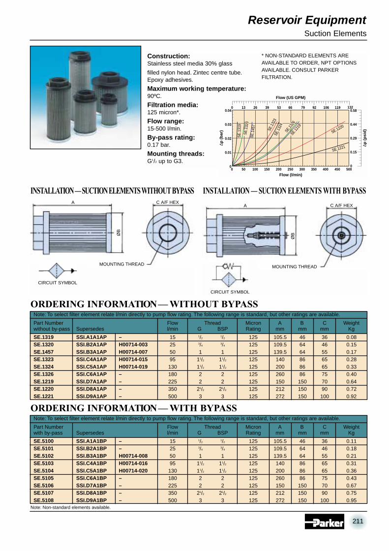
Construction:Stainless steel media 30% glass
filled nylon head. Zintec centre tube.Epoxy adhesives.
Maximum working temperature:90ºC.
Filtration media:125 micron*.
Flow range:15-500 l/min.
By-pass rating:0.17 bar.
Mounting threads:G1/2 up to G3.
* NON-STANDARD ELEMENTS AREAVAILABLE TO ORDER, NPT OPTIONSAVAILABLE. CONSULT PARKERFILTRATION.
SE.1
319
0 50 100 500450150 200 250 300 350 400
Flow (l/min)
∆p (
bar
)
0
0.01
0.04
0.03
0.02
0.58
0.44
0.29
0.15
0
∆p (
psi
d)
0 13 39 79 132
Flow (US GPM)
11926 53 66 92 106
SE.1
457
SE.1221
SE.1220
SE.1219
SE.1326
SE.1
324
SE.1
323
SE.1
320
211
07 RESERVOIR EQUIPMENT 28/6/02 3:57 pm Page 211

INSTALLATION DETAILS
ORDERING INFORMATION
To select coupling model check application toestablish running load condition.
Check chart for factor (F) and apply factor (F) to*Rating of coupling formulae. This answer you applyto *Rating/100 rev/min below.
It is advisable always to check shaft sizes being usedon application and check with dimension ‘H’.
F
Factor (F)Application Electric Motor Petrol/Diesel engineUniform load 1.00 1.20Medium shock 1.25 1.50Heavy shock 1.75 2.00
HP of application x 100 x F*Rating of coupling= rev/min of application
G
A A
GRUB SCREW POSITION
HUB WITHDRAWALCLEARANCE
E
D
ØJ
ØH
ØC
ØB
HUB WITHDRAWAL CLEARANCE
SECTIONED DETAIL
Ordering examplesParker Filtration Drive coupling components are ordered separately.Here are three examples of complete assemblies ordered this way.1. Complete assembly – DC.28.M14.B04K
Made up of a DC.28.M14DC.28.B04KDC.28.S (Sleeve)
Complete model DC.28 drive coupling: One Gear Hub has 14mmbore with 5mm wide keyway and other hub has a 1/2” bore with 0.125”wide keyway.Both hubs supplied with locating grub screw.
2. Complete assembly – DCR.42.PB.PBMade up of 2x DCR.42.PB’s
DC.42.S (Sleeve)Complete model DC.42 drive coupling: Both Gear Hubs have pilotbore of 10.5mm. Not supplied with grub screws.3. Complete assembly – DCR.55.PB.B12K
Made up of a DCR.55.PBDC.55.B12KDC.55.S (Sleeve)
Complete model DC.55 drive coupling: One Gear Hub pilot bored 5/8”,the other hub pilot bored 11/2”. Latter only supplied with grub screw.
Reservoir EquipmentDrive Couplings
TECHNICAL DATAMaterials ofConstructionCoupling HalvesSintered SleevesSleeveNylon 66Max Temp Sleeve83°C
212
07 RESERVOIR EQUIPMENT 28/6/02 3:57 pm Page 212

Height of Keyway from Base of BoreMETRIC IMPERIAL
Standard Bore BS 4500, (1985) BS 1916, Part 1, (1985)Standard Keyway BS 4325, Part 1 (1980) BS 46, Part 1, (1985)
ASSEMBLY DATA1. Maximum angular misalignment is ±2°. Maximum radial misalignment is ±0.4mm.
2. Ensure that the Parker Filtration Drive Coupling gear hubs arean easy fit to their respective shafts. Do not use heavy blows to force the hubs on.
3. When in position, the hubs should have a gap of 4mm as denoted by ‘E’ dimension.
4. Tighten grub screws to locate both gear hubs on to their respective shafts.
Coupling half pilot boredØ Bore 8mm
Drive Coupling Sleeve
Reservoir EquipmentDrive Couplings
DC.28DC.42DC.55
5000 0.75 1.00 0.4 40.0 66.0 44.5 38.0 4.0 104.0 84.0 28.0 10.0 7.05000 1.32 1.75 0.75 42.0 90.0 60.0 42.0 4.0 115.0 88.0 42.0 14.0 10.54000 6.00 8.00 2.05 59.0 125.0 83.0 65.0 4.0 158.0 122.0 55.0 19.0 16.0 min
38.1 max
ORDERING INFORMATIONMax *Rating/ –H– J
Speed 100 rev/min Weight A B C D E F G Max Min PilotPart Number rev/min kW hp mm mm mm mm mm mm mm Bore Bore Bore
DC.28.M10DC.28.M11DC.28.M14DC.28.M16DC.28.M18DC.28.M19DC.28.M20DC.28.M22DC.28.M24DC.28.M25DC.28.M28
10.0mm11.0mm14.0mm16.0mm18.0mm19.0mm20.0mm22.0mm24.0mm25.0mm28.0mm
3.0mm4.0mm5.0mm5.0mm6.0mm6.0mm6.0mm6.0mm8.0mm8.0mm8.0mm
11.5mm12.9mm16.4mm18.4mm20.9mm21.9mm22.9mm24.9mm27.5mm28.5mm31.5mm
Weight rangefrom .267 Kg
to .411 Kg
Coupling halves with Metric Bore and KeywayKeyway
Part Number ØBore Width Height
Model DC.28
DC.42.M18DC.42.M19DC.42.M20DC.42.M22DC.42.M24DC.42.M25DC.42.M28DC.42.M30DC.42.M32DC.42.M35DC.42.M38DC.42.M42
18.0mm19.0mm20.0mm22.0mm24.0mm25.0mm28.0mm30.0mm32.0mm35.0mm38.0mm42.0mm
6.0mm6.0mm6.0mm6.0mm8.0mm8.0mm8.0mm8.0mm10.0mm10.0mm10.0mm12.0mm
20.9mm21.9mm22.9mm24.9mm27.5mm28.5mm31.5mm33.5mm35.5mm38.5mm41.5mm45.5mm
Weight rangefrom .436 Kg
to .75 Kg
Coupling halves with Metric Bore and KeywayKeyway
Part Number ØBore Width Height
Model DC.42
DC.28.B03KDC.28.B04KDC.28.B05KDC.28.B06KDC.28.B07KDC.28.B08KDC.28.B09K
DCR.28.PB
DC.28.S
7/16
1/2
5/8
3/4
7/8
111/8
0.125 ins0.125 ins0.188 ins0.188 ins0.250 ins0.250 ins0.313 ins
0.50 ins0.57 ins0.72 ins0.84 ins0.99 ins1.12 ins1.24 ins
Weight rangefrom .259 Kg
to .411 Kg
Coupling halves with Imperial Bore and KeywayKeyway
Part Number ØBore Width Height
Part Number
Part Number
11/8
11/4
13/8
11/2
15/8
13/4
17/8
221/8
0.313 ins0.313 ins0.375 ins0.375 ins0.439 ins0.439 ins0.501 ins0.501 ins0.626 ins
1.24 ins1.37 ins1.49 ins1.61 ins1.76 ins1.89 ins2.01 ins2.13 ins2.31 ins
Weight rangefrom 1.248 Kg
– 2.046 Kg
DC.42.B05KDC.42.B06KDC.42.B07KDC.42.B08KDC.42.B09KDC.42.B10KDC.42.B11KDC.42.B12KDC.42.B13K
DC.42.PB
DC.42.S
Weight rangefrom .448 Kg
to .753 Kg
Coupling half pilot boredØ Bore 12mm
Drive Coupling Sleeve
Coupling half pilot boredØ Bore 16mm
Drive Coupling Sleeve
5/8
3/4
7/8
111/8
11/4
13/8
11/2
15/8
0.188 ins0.188 ins0.250 ins0.250 ins0.313 ins0.313 ins0.375 ins0.375 ins0.439 ins
0.72 ins0.84 ins0.99 ins1.12 ins1.24 ins1.37 ins1.49 ins1.61 ins1.76 ins
Coupling halves with Imperial Bore and KeywayKeyway
Part Number ØBore Width Height
Part Number
Part Number
DC.55.B09KDC.55.B10KDC.55.B11KDC.55.B12KDC.55.B13KDC.55.B14KDC.55.B15KDC.55.B16KDC.55.B17K
DCR.55.PB
DC.55.S
Coupling halves with Imperial Bore and KeywayKeyway
Part Number ØBore Width Height
Part Number
Part Number
DC.55.M25DC.55.M28DC.55.M30DC.55.M32DC.55.M35DC.55.M38DC.55.M42DC.55.M55
25.0mm28.0mm30.0mm32.0mm35.0mm38.0mm42.0mm55.0mm
8.0mm8.0mm8.0mm10.0mm10.0mm10.0mm12.0mm16.0mm
28.5mm33.5mm33.5mm35.5mm38.5mm41.5mm45.5mm59.5mm
Weight rangefrom 1.248 Kg
to 1.932 Kg
Coupling halves with Metric Bore and KeywayKeyway
Part Number ØBore Width Height
Model DC.55
213
07 RESERVOIR EQUIPMENT 28/6/02 3:57 pm Page 213

Reservoir EquipmentMulticlamp
SPECIFICATIONWhen only the best ClampingSystem will do....specify Multiclamp
Multiclamp is a system. A system ofcomponents, each one engineered toa high standard – that together build toprovide effective, all-purpose pipeworkclamping. Multiclamp offers creativeand cost-effective environmentalbenefits to the system designer andinstaller. Creating accurate runs ofvarying diameter tubes, pipes, hosesand cables in all industries.
Secure Multiclamp installationsensure a leak free, noise freeand vibration free system.
The neat design of pipe line runsoffers easy maintenance of machineryand plant equipment. Visual planningof lines runs is straightforward withMulticlamp – accurate installationscan be achieved without skilled labour– keeping costs down and quality up.
MATERIAL SPECIFICATIONS
Single and double clamping units are ordered in sets only. i.e. 1 set of clamping units = 10 pairs. Multiclamp is not ordered inset. i.e. 1-off clamping unit = 1 upper and 1 lower clamping unit.
Zinc plated steel with anti-corrosive, full passivate. Multiclamp can alsobe multi-stacked using stacking studs and nuts. Series 10 and 16clamp is supplied in lengths of 603mm and Series 32 in lengths of1206mm. These can be simply cut to the required lengths forinstallation.
Series 10 will accept pipe or hose diameters from 6mm up to 20mmmaximum. Series 16 from 6mm up to 28mm and Series 32 from 10mmup to 50mm. Across the 3 Series, there are 26 different high-qualitysplit rubber bushes to select from to cope with any combination andnumber of different pipe and hose diameters in the same run.
Single Clamp
Multiclamp — 16 holes Split Bushes
Double Clamp
B C CTS ( B )
Ø
A
E
F R
EF
B C C B
D
A
E
F
SERIES 10PAT.1170557
SERIES 10PAT.1170557
THETFORDENGLAND
C
GH R
EF
A BØ
D E
F
Ø
B
A
PIPE SIZE
1 set of clamping units = 1 pair Split bushes are ordered in sets onlyi.e. 1 set of bushes = 10 bushes of one size
214
07 RESERVOIR EQUIPMENT 28/6/02 3:57 pm Page 214

Reservoir EquipmentMulticlamp
Components Fixing Methods
Clamping Unit
A dual purpose unit which provides both halves of a completeclamp. Supplied in various sizes which provides for easy installationor removal of tube fittings using conventional methods. This simplecomponent forms the basis of the Multiclamp system.
Weld Plate
When Multiclamp is required to be secured by welding, insertstandard bolt into WELD PLATE. Hexagon head of Standard Bolt isretained in hexagonal recess on underside of WELD PLATE, leavinga flush surface for mounting. Secure to lower clamping unit withSTACKING NUT (finger tight). Repeat for each welding position.Assemble lower clamping unit to mounting surface by welding eachWELD PLATE and finally tighten each STACKING NUT beforeproceeding with remainder of installation.
Split Bushing
Made from an ethylene – propylene copolymer (EPDM). The bushesexhibit excellent capability to absorb vibrationary loads applied byretained pipework and reduced noise transmission from pipework tosurrounding metal supports etc. The bushes have good mechanical
properties and are highlyresistant to ozoneweathering and a wide rangeof chemicals. They offer agood electrical insulationand are suitable for use overa wide temperature range.Note that if bushes arerequired for immersion inmineral oils, an alternativematerial is recommended.
Stacking Nut
Used in conjunction with STACKING STUD forcontinuous stacking of CLAMPING UNITS. Thisholds two units firmly together in suspensionand secures the lower unit to a base column orsupport. The STACKING NUT and STACKINGSTUD maintains correct alignment as eachMulticlamp is progressively stacked. It is simplyfixed and allows for the upper unit to be securelyfastened in place by a standard bolt.
Mounting Adaptor
A metal bushing that fits into the line opening of the clamping unit.Similar to a split bushing, this component accommodates standard
attaching bolts when makinga suspended mount of aplate or column. A bridge-type mount can be formedby using one adaptor oneach end of a Multiclamp.The adaptors are available insizes to suit all Seriesclamping units.
Stacking Stud
The STACKING STUD can bethreaded into a tapped hole in themounting base or plate, then theSTACKING NUT is tightened downsecurely with a spanner.
Mounting Adaptor
A MULTICLAMP can be secured and suspended from a column ormounting plate by using MOUNTING ADAPTORS and standardattaching bolts. Additional MULTICLAMPS can also be stacked on tothe mounted clamp.
Stacking Stud and Nut
When mounting plate has athickness of 9.5mm (3/8”) or less,STACKING STUD should bescrewed into STACKING NUT andstud passed through drilled hole andsecured with a retaining nut.
215
07 RESERVOIR EQUIPMENT 28/6/02 3:57 pm Page 215

Your maximum pipe size will determine the series to use. There is adegree of versatility provided by the rubber bushes. You choose fromsingle or multistacked Multiclamp, whichever suits your particularinstallation requirements.
Reservoir EquipmentMulticlamp
PLANNING WITH MULTICLAMP
Planning with MulticlampThese notes have been compiled to assist in planning yourMulticlamp system.
Multiclamp offers considerable flexibility. For example, it can fitin with a factory installation that is being built in phases.
Should a last minute change in pipe diameter occur duringinstallation, an alternative rubber bush is likely to be all that isrequired. Not a complete and expensive re-think of theinstallation.
Multiclamp metal components can be sprayed to match avehicle livery or plant installation and, if installed properly,should require no maintenance.
Installation is simple and requires no experienceAnyone can use Multiclamp and only the basic, everyday toolsare required.
From one pipe to almost any number – because eachMulticlamp ‘position’ can be visually sighted and its positionadjusted – an almost guaranteed straight run can be obtained.Equally, changes of plane or direction can be achieved simplyand securely.
Group pipe sizes together to obtain the most economical useof three basic Multiclamp Series.
Some sites will require all pipes mounted in one single plane– either vertical or horizontal.
When stacked modules are preferred, the only work to bedone on the Multiclamp is to saw off the desired length.
If a large number of pipe lines are to be run, it isrecommended that the upper clamping unit is simply cut intotwo lines only, and progressively assembled by securing twopipes at a time. It will be recognised that most odd lengths onsite will be used, and one man can easily cope with a largenumber of pipe lines by this simple progressive build up. Thisassembly will provide easy access for servicing and replacingpipes. This method also reduces the quantity of Stacking Nutsand Studs by 50%.
If a factory installation is being built in phases, it would bewise to leave the first phase with a lower clamping unit andStacking Nuts in position ready to receive pipe runs for thenext building phase.
Series 106.0mm-20.0mm(1/4”-3/4”)
Series 166.0mm-28.0mm(1/4”-1”)
Series 3210.0mm-50.0mm(3/8”-2”)
Stacked modules or single module
Fixing points to suit
Stacking stud andnut not requiredin this position
Just consider the savings when Multiclamp is planned really wisely.How far apart should Multiclamp be spaced?
Clamp in position for phase 2
Pha
se 1
216
07 RESERVOIR EQUIPMENT 28/6/02 3:57 pm Page 216

Reservoir EquipmentMulticlamp
DimensionsA 11.0mmB 33.0mm
Thread M8-1.25
ORDERING INFORMATION — SERIES 1O
Part Number MC.N.10
Stacking Nuts(50 per part number)
Weight: 0.80 Kg (per set)
DimensionsA 13.3mmB 25.0mmC 10.0mmD 6.3mmE 25.0mmF 8.5mm
Part Number MC.WP.10
Weld Plates(10 per part number)
Weight: 0.35 Kg (per set)
Series Thread Length10 M8-1.25 16.0mm
Part Number MC.SB.10
Standard Bolts(50 per part number)
DimensionsA 32.0mmB 21.0mmC 4.5mm
Thread M8-1.25
Part Number MC.S.10
Stacking Studs(50 per part number)
Weight: 0.48 Kg (per set)
DimensionsA 27.0mmB 25.0mmØ 8.7mm
Part Number MC.B.10.MO
Mounting Adaptors(1 piece per part number)
Weight: 0.020 Kg (per set)
DimensionsA 11.0mmB 44.0mm
Thread M8-1.25
ORDERING INFORMATION — SERIES 16
Part Number MC.N.16
Stacking Nuts(50 per part number)
Weight: 1.06 Kg (per set)
DimensionsA 13.3mmB 25.0mmC 10.0mmD 6.3mmE 25.0mmF 8.5mm
Part Number MC.WP.10
Weld Plates(10 per part number)
Weight: 0.35 Kg (per set)
Series Thread Length16 M8-1.25 16.0mm
Part Number MC.SB.10
Standard Bolts(50 per part number)
DimensionsA 32.0mmB 21.0mmC 2.0mm
Thread M8-1.25
Part Number MC.S.10
Stacking Studs(50 per part number)
Weight: 0.020 Kg (per set)
DimensionsA 27.0mmB 36.0mmØ 8.7mm
Part Number MC.B.16.MO
Mounting Adaptors(1 single piece per part number)
Weight: 0.060 Kg (per set)
DimensionsA 13.0mmB 71.5mm
Thread M10-1.50
ORDERING INFORMATION — SERIES 32
Part Number MC.N.32
Stacking Nuts(50 per part number)
Weight: 1.99 Kg (per set)
DimensionsA 17.5mmB 32.0mmC 12.0mmD 8.0mmE 32.0mmF 11.0mm
Part Number MC.WP.32
Weld Plates(10 per part number)
Weight: 0.70 Kg (per set)
Series Thread Length32 M10-1.50 30.0mm
Part Number MC.SB.32
Standard Bolts(50 per part number)
DimensionsA 38.0mmB 22.0mmC 2.0mm
Thread M10-1.50
Part Number MC.S.32
Stacking Studs(50 per part number)
Weight: 0.90 Kg (per set)
DimensionsA 40.0mmB 58.0mmØ 10.7mm
Part Number MC.B.32.MO
Mounting Adaptors(1 single piece per part number)
Weight: 0.260 Kg (per set)
217
07 RESERVOIR EQUIPMENT 28/6/02 3:57 pm Page 217

Reservoir EquipmentMulticlamp
SPECIFICATION
1. Upper and Lower Clamping Unit
4. Stacking Nut 5. Weld Plate 3. Stacking Stud 6. Standard Bolt
2. Various sizes of Split Bushings
Typical Single Clamp with exploded view
Multiclamp — 16 holes Split Bushes
Typical Double Clamp with exploded view
1
2
4
5
6
3
Stacking Nuts
Stacking nuts areordered in sets only.i.e. 1 set of stackingnuts = 50 stackingnuts of one size.
Mounting Adaptors
Mounting adaptorsare not ordered insets. i.e. 1 offmounting adaptors= 1 single piece.
Stacking Studs
Stacking studs areordered in sets only.i.e. 1 set of stackingstuds = 50 stackingstuds of one size.
Weld Plates
Weld plates areordered in sets only.i.e. 1 set of weldplates = 10 weldplates.
AB
TH
RE
AD
TH
RE
AD
A
B
B
B
A
A
Ø
C
D
EF
218
07 RESERVOIR EQUIPMENT 28/6/02 3:57 pm Page 218

.130 Kg
.130 Kg
.120 Kg
.120 Kg
.100 Kg.090 Kg
MC.G.10.4MC.G.10.5MC.G.10.6MC.G.10.8MC.G.10.10MC.G.10.12
6 1/4 –8 5/16 –10 3/8 –
12-14 1/21/4
15-16 5/83/8
18-20 3/4 –
Reservoir EquipmentMulticlamp
DimensionsA 25.0mmB 8.5mmC 38.1mmD 55.0mmE 19.0mmF 38.0mmØ 9.0mm
ORDERING INFORMATION — SERIES 1O ( 6mm-20mm pipe dia.)
Part Number MC.10.1
Single Clamp (10 pairsper part number)
DimensionsA 25.0mmB 8.5mmC 38.1mmD 93.0mmE 19.0mmF 38.0mmØ 9.0mm
Part Number MC.10.2
Double Clamp (10 pairsper part number)
DimensionsA 34.0mmB 38.1mmC 25.0mmD 15.0mmE 38.1mmF 601.5mmG 19.0mmH 38.0mmØ 9.0mm
Part Number MC.10.16
Multiclamp (1 pair perpart number)
Split Bushes (10 pairs per part number)
Pipe Size A Bmm O/D NB 25.5mm 27.0mm 34.0mm
Part No. Weight Weight
Weight: 0.60 Kg (per set) Weight: 1.0 Kg (per set)
Weight: 0.80 Kg (per pair)
Quoted weights based on a pack of 10
.280 Kg
.280 Kg
.280 Kg
.260 Kg
.220 Kg
.200 Kg
.180 Kg
.140 Kg.160 Kg
MC.G.16.4MC.G.16.5MC.G.16.6MC.G.16.8MC.G.16.10MC.G.16.12MC.G.16.14MC.G.16.16MC.G.16.18
6 1/4 –8 5/16 –10 3/8 –
12-14 1/21/4
15-16 5/83/8
18-20 3/4 –22 7/8
1/2
25 1 3/4
28 – –
DimensionsA 25.0mmB 7.0mmC 50.8mmD 65.0mmE 23.8mmF 47.6mmØ 9.0mm
ORDERING INFORMATION — SERIES 16 ( 6mm-28mm pipe dia.)
Part Number MC.16.1
Single Clamp (10 pairsper part number)
DimensionsA 25.0mmB 7.0mmC 50.8mmD 116.0mmE 23.8mmF 47.6mmØ 9.0mm
Part Number MC.16.2
Double Clamp (10 pairsper part number)
DimensionsA 47.0mmB 50.8mmC 25.0mmD 21.0mmE 50.8mmF 608.8mmG 25.0mmH 51.0mmØ 9.0mm
Part Number MC.16.12
Multiclamp – 12 holes(1 pair per part number)
Split Bushes (10 per part number)
Pipe Size A Bmm O/D NB 35.4mm 27.0mm 34.0mm
Part No. Weight Weight
Weight: 0.80 Kg (per set) Weight: 1.6 Kg (per set)
Weight: 1.0 Kg (per set)MC.G.16.14 Dimension ‘A’ is 38.0mm
1.30 Kg1.20 Kg1.10 Kg1.10 Kg1.00 Kg1.00 Kg1.00 Kg0.80 Kg0.80 Kg0.60 Kg0.40 Kg
MC.G.32.6MC.G.32.8MC.G.32.10MC.G.32.12MC.G.32.14MC.G.32.16MC.G.32.18MC.G.32.20MC.G.32.24MC.G.32.26MC.G.32.32
10 3/8 –12-14 1/2
1/4
15-16 5/83/8
18-20 3/4 –22 7/8
1/2
25 1 3/4
28-30 – 3/4
32-34 11/4 135-38 11/2 –
42 – 11/4
50 2 11/2
DimensionsA 40.0mmB 9.4mmC 76.2mmD 95.0mmE 38.0mmF 76.2mmØ 11.1mm
ORDERING INFORMATION — SERIES 32 ( 10mm-50mm pipe dia.)
Part Number MC.32.1
Single Clamp (10 pairsper part number)
DimensionsA 41.0mmB 9.4mmC 76.2mmD 171.0mmE 38.0mmF 76.2mmØ 11.1mm
Part Number MC.32.2
Double Clamp (10 pairsper part number)
DimensionsA 72.0mmB 76.2mmC 40.0mmD 34.0mmE 76.2mmF 1211.0mmG 38.5mmH 77.0mmØ 11.0mm
Part Number MC.32.16
Multiclamp – 16 holes(1 pair per part number)
Split Bushes (10 per part number)
Pipe Size A Bmm O/D NB 59.0mm 44.5mm
Part No. Weight
Weight: 2.25 Kg (per set) Weight: 3.82 Kg (per set)
Weight: 3.8 Kg (per pair)
219
07 RESERVOIR EQUIPMENT 28/6/02 3:57 pm Page 219

Reservoir EquipmentSpeed Control and Needle Valves
SPECIFICATIONConstruction:Brass 58 – UNI 5705 (G3/4 model-
steel) Nickel plated.
Max. working pressure:210 bar.
Operating temp. range:-20°C to +100°C.
Fluid compatibility:Petroleum-based oils.
Sizes:G1/4, G3/8, G1/2 and G3/4.
Speed control valve/checkvalve crack pressure:0.5 bar.
Panel mounting:A retaining nut for panel mountingis included with every option.
Filtration recommendation:Parker Filtration 25 micron absolutesystem filtration is desirable toensure acceptable reliability andservice life.
ØC
B
D
A B F
PANEL MOUNTINGTHREAD G
PANEL MOUNTINGTHREAD M40 x 1.5
132.
0 M
AX
PORT IDENTIFICATION
Ø47.0
40.0
24.0
A
BA
E
G1/4, G3/8 and G1/2 options G3/4 option
ORDERING INFORMATION
SCV.1700 G1/4, 210 bar speed control 36 60 22 11 55.5 16.5 M17 x 1 0.13SCV.1701 G3/8, 210 bar speed control 41.5 72.5 27 15 64.5 21.5 M20 x 1 0.24SCV.1702 G1/2, 210 bar speed control 57 85 33 19 87 27 M25 x 1.5 0.45SCV.1703 G3/4, 210 bar speed control 85 42.5 – – – – M40 x 1.5 1.3
A B C D E F G WeightPart Number Description mm mm mm mm mm Size Panel mtg thread Kg
Speed Control Valves – white caps
2000 G1/4, 210 bar needle valve 36 60 22 11 55.5 16.5 M17 x 1 0.132001 G3/8, 210 bar needle valve 41.5 72.5 27 15 64.5 21.5 M20 x 1 0.242002 G1/2, 210 bar needle valve 57 85 33 19 87 27 M25 x 1.5 0.452003 G3/4, 210 bar needle valve 115 73 – – – – M40 x 1.5 1.6
A B C D E F G WeightPart Number Description mm mm mm mm mm Size Panel mtg thread Kg
Needle Valves – orange caps
220
07 RESERVOIR EQUIPMENT 28/6/02 3:57 pm Page 220

Reservoir EquipmentSpeed Control and Needle Valves
TECHNICAL DATA
0 .3 1.6 4.2 6.4
Flow (US GPM)
5.81.1 2.1 3 4.7 5
Flow (l/min)
3.1 3.7
0 2 4 24226 10 12 14 16 208 18
∆p (
bar
)
20
0
18
16
14
12
10
2
4
6
8
290
232
145
87
0
∆p (
psi
d)
261
174
116
29
203
58
1 2 3 4 5 6
FULLY OPEN
∆p (
bar
)
0 18
Flow (US GPM)
3 5 8 11 13 1620
0
18
16
14
12
10
2
4
6
8
290
232
145
87
0
∆p (
psi
d)
261
174
116
29
203
58
Flow (l/min)0 20 40 60 7010 30 50
2 3 4 5 6
FULLY OPEN
7 8
2000/SCV.1700 – Flow setting in no. of turns 2002/SCV.1702 – Flow setting in no. of turns
∆p (
bar
)
OPENCLOSED
0 18
Flow (US GPM)
3 5 8 11 13 1620
0
18
16
14
12
10
2
4
6
8
290
232
145
87
0
∆p (
psi
d)
261
174
116
29
203
58
Flow (l/min)0 20 40 60 7010 30 50
Flow (l/min)
∆p (
bar
)
OPEN
CLOSED
0 20 40 20060 80 100 120 140 160 180
0 5 21 37 53
Flow (US GPM)
11 16 26 31 42 4720
0
18
16
14
12
10
2
4
6
8
290
232
145
87
0
∆p (
psi
d)
261
174
116
29
203
58
SCV.1700 – Flow setting (fully closed/fully open) SCV.1702 – Flow setting (fully closed/fully open)
0 9.3
Flow (US GPM)
1.3 3 4.3 5 6.3 8
Flow (l/min)0 10 20 30 355 15 25
∆p (
bar
)
20
0
18
16
14
12
10
2
4
6
8
290
232
145
87
0
∆p (
psi
d)
261
174
116
29
203
58
2 3 4 5 6
FULLY OPEN
Flow (l/min)
∆p (
bar
)
0 20 40 12060 80 100
0 3 11 21 31
Flow (US GPM)
5 8 13 18 24 2920
0
18
16
14
12
10
2
4
6
8
290
232
145
87
0
∆p (
psi
d)
261
174
116
29
203
58
10 30 50 70 90 110
16 26
FULLY OPEN
2 3 4 5 6 7 8 9
2001/SCV.1701 – Flow setting in no. of turns
Flow (l/min)
∆p (
bar
)
CLOSED
0 20 40 12060 80 100
0 3 11 21 31
Flow (US GPM)
5 8 13 18 24 2920
0
18
16
14
12
10
2
4
6
8
290
232
145
87
0
∆p (
psi
d)
261
174
116
29
203
58
10 30 50 70 90 110
16 26
OPEN
SCV.1701 – Flow setting (fully closed/fully open)
Flow (l/min)
∆p (
bar
)
OPEN
CLOSED
0 20 40 20060 80 100 120 140 160 180
0 5 21 37 53
Flow (US GPM)
11 16 26 31 42 4720
0
18
16
14
12
10
2
4
6
8
290
232
145
87
0
∆p (
psi
d)
261
174
116
29
203
58
SCV.1703 – Flow setting (fully closed/fully open)
2003/SCV.1703 – Flow setting in no. of turns
PRESSURE DROP ( P) FLOW CHARACTERISTICS WITH MINERAL OIL AT 30 cSt VISCOSITYGraphs for needle/shut-off valves and speed control valves with flow A-B (controlled flowthrough needle).
Flow setting by number of turns of control knob is indicated on the body graduated scale.
Graphs for speed control valves. Flow B-A (flow through check valve), with needle valveportion in fully open and fully closed positions.
A B A BA B
SYMBOL
221
07 RESERVOIR EQUIPMENT 28/6/02 3:57 pm Page 221

Reservoir EquipmentInline Check Valves
SPECIFICATION
INSTALLATION DETAILS
TECHNICAL DATA
Construction:Steel UNI 5105.
Ball and spring:Chrome finished steel.
Retainer:Nylon.
Flow rates:From 20 l/min to 150 l/min.
Max. working pressure:350 bar.
Valve crack pressures:0.35 and 4.5 bar.
CIRCUIT SYMBOL
A B A/F HEX
THREAD
2301
2302
2303
2304
2305
2311
2312
2313
2314
2315
20
30
50
100
150
20
30
50
100
150
0.35
0.35
0.35
0.35
0.35
4.50
4.50
4.50
4.50
4.50
1/4
3/8
1/2
3/4
11/4
3/8
1/2
3/4
1
54
66
77
88
108
54
65
77
88
108
19
24
30
36
46
19
24
30
36
46
0.09
0.17
0.32
0.48
0.99
0.09
0.17
0.32
0.48
0.99
ORDERING INFORMATIONCracking
Flow Pressure Thread A B WeightPart Number l/min bar G mm mm Kg
2301
2302
2303
2304
2305
0 20 40 22020060 80 100 120 140 160 180
Flow (l/min)
∆p (
bar
)
0
0.5
1.0
4.0
3.5
3.0
2.5
2.0
1.5
58
43.5
29
14.5
0
∆p (
psi
d)
0 5 21 37 58
Flow (US GPM)
5311 16 26 31 42 47
Pressure Drop Flow Curves
222
07 RESERVOIR EQUIPMENT 28/6/02 3:57 pm Page 222
Reservoir EquipmentGauge Isolator Valves
SPECIFICATION
SINGLE STATION INSTALLATION DETAILS
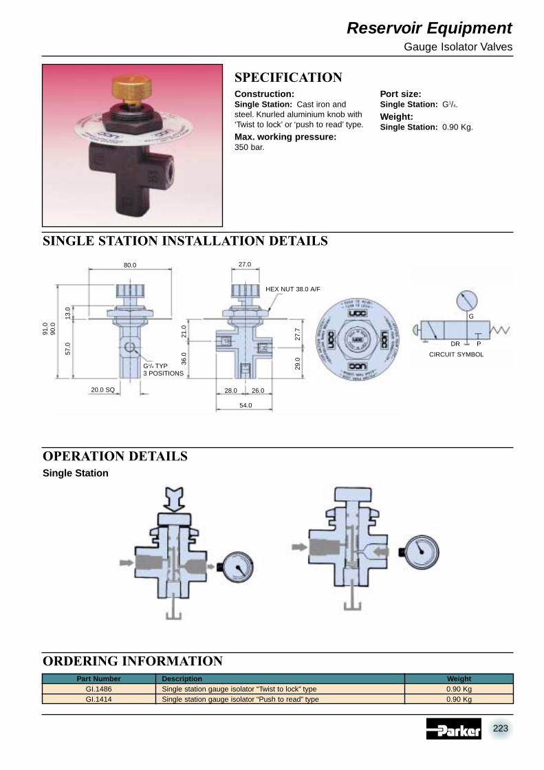
Construction:Single Station: Cast iron andsteel. Knurled aluminium knob with‘Twist to lock’ or ‘push to read’ type.
Max. working pressure:350 bar.
Port size:Single Station: G1/4.
Weight:Single Station: 0.90 Kg.
Part NumberGI.1486GI.1414
Part Number DescriptionSingle station gauge isolator “Twist to lock” typeSingle station gauge isolator “Push to read” type
Description Weight0.90 Kg0.90 Kg
Weight
OPERATION DETAILS
ORDERING INFORMATION
Single Station
80.0
20.0 SQ
13.0
57.0
91.0
90.0
G1/4 TYP3 POSITIONS
CIRCUIT SYMBOL
27.0
28.0
54.0
26.0
29.0
27.7
21.0
36.0
HEX NUT 38.0 A/F
G
PDR
223
07 RESERVOIR EQUIPMENT 28/6/02 3:57 pm Page 223

Reservoir Equipment
SPECIFICATIONConstruction:Case: Natural finish stainless
steel.Window: Non-splintering clear
acrylic glass.Movement: Cu alloy.Dial: White plastic, with
pointer stop pin.Pointer: Black plastic.Liquid filling:Glycerine 99.7%.Working pressure:Max 75% of the full scale value.
Process temperature:+ 60°C maximum.Accuracy:1.6% FSD.Wetted parts connector:Copper alloy.Bourdon tube:< 60 bar = Cu alloy, C-type,soft soldered.> 60 bar = Cu alloy, helical type,soft soldered.
63mm Dia. Pressure Gauges
0-10 bar0-16 bar0-25 bar0-40 bar0-60 bar0-100 bar0-160 bar0-250 bar0-400 bar0-600 bar
PG.4561109PG.4561110PG.4561112PG.4561114PG.4561115PG.4561117PG.4561118PG.4561120PG.4561122PG.4561123
0.260.260.260.260.260.260.260.260.260.26
PGF.0631.010PGF.0631.016PGF.0631.025PGF.0631.040PGF.0631.060PGF.0631.100PGF.0631.160PGF.0631.250PGF.0631.400PGF.0631.600
Part Number Description Supersedes Weight Kg
0-10 bar0-16 bar0-25 bar0-40 bar0-60 bar0-100 bar0-160 bar0-250 bar0-400 bar0-600 bar
PG.4531109PG.4531110PG.4531112PG.4531114PG.4531115PG.4531117PG.4531118PG.4531120PG.4531122PG.4531123
PGC.0631.010PGC.0631.016PGC.0631.025PGC.0631.040PGC.0631.060PGC.0631.100PGC.0631.160PGC.0631.250PGC.0631.400PGC.0631.600
Part Number Description Supersedes
0-4 bar0-10 bar0-16 bar0-25 bar0-40 bar0-60 bar0-100 bar0-160 bar0-250 bar0-400 bar0-600 bar
–PG.4511109PG.4511110PG.4511112PG.4511114PG.4511115PG.4511117PG.4511118PG.4511120PG.4511122PG.4511123
PGB.0631.004PGB.0631.010PGB.0631.016PGB.0631.025PGB.0631.040PGB.0631.060PGB.0631.100PGB.0631.160PGB.0631.250PGB.0631.400PGB.0631.600
Part Number Description Supersedes
INSTALLATION DETAILS
ORDERING INFORMATIONMounting Stem Detail
Note: It is recommended that all glycerine gauges should bemounted in the vertical position with gauge case relief valveuppermost. Pressure range up to 1000 bar available.
Bottom connection
Panel Mounting
Panel Mounted (3-hole flange)
*Note: Any subsequent changes to gauge accuracy will be notified.
13 32 68 62 6.5 G1/4 54 14 0.21
a b D1 D2 e G h SW Weight±0.5 ±1 Kg
Dimensions (mm) Bottom Connection
32 56 68 62 6.5 G1/4 14 0.21
b b2 D1 D2 e G SW Weight±0.5 ±1 Kg
Dimensions (mm) Panel Mounting (Centre Back)
Note 1: Panel cut-out 64.5 ±0.5Note 2: 13mm on the outside radius required to allow for fixing clamp.
Panel Mounting (Centre Back)Bottom connection
Panel Mounted (3-hole flange)
75 85 3.6
D1 D2 D3
Dimensions (mm)
Note 1: Gauge dimensions as forPanel Mounting option abovewith flange as shown below.
Note 2: Panel cut-out for 3-holemounting 67±0.3.
ØD2
ØD1
120°
120°
ØD3
SYMBOL
25
23
15
2
Ø9.
5Ø5
SNUBBER FITTEDG1/4 (1/4” BSP)
14 A/F HEX
D1
SW
G
h
ØD
2
b
a
e
SW
e
ØD
2
bb2
G
D1
224
07 RESERVOIR EQUIPMENT 28/6/02 3:57 pm Page 224

Reservoir Equipment
SPECIFICATIONConstruction:Case: BS 304 S15 stainless
steel.Window: Acrylic.Movement: Brass.Dial: White aluminium.Pointer: Black aluminium.Liquid filling:Glycerine 98%.Working pressure:Full scale value.
Process temperature:+ 60°C maximum.Accuracy:1.0% FSD.Wetted parts connector:Copper alloy.Bourdon tube:< 100 bar = Cu alloy, c-type,soft soldered.> 100 bar = stainless steel 1.4571,helical type, brazed.
100mm Dia. Pressure Gauges
0-10 bar0-16 bar0-25 bar0-40 bar0-60 bar0-100 bar0-160 bar0-250 bar0-400 bar0-600 bar0-1000 bar
PG.4861109PG.4861110PG.4861112PG.4861114PG.4861115PG.4861117PG.4861118PG.4861120PG.4861122PG.4861123PG.4861125
1.01.01.01.01.01.01.01.01.01.01.0
PGF.1001.010PGF.1001.016PGF.1001.025PGF.1001.040PGF.1001.060PGF.1001.100PGF.1001.160PGF.1001.250PGF.1001.400PGF.1001.600PGF.1001.1000
Part Number Description Supersedes Weight Kg
0-10 bar0-16 bar0-25 bar0-40 bar0-60 bar0-100 bar0-160 bar0-250 bar0-400 bar0-600 bar0-1000 bar
PG.4831109PG.4831110PG.4831112PG.4831114PG.4831115PG.4831117PG.4831118PG.4831120PG.4831122PG.4831123PG.4831125
PGE.1001.010PGE.1001.016PGE.1001.025PGE.1001.040PGE.1001.060PGE.1001.100PGE.1001.160PGE.1001.250PGE.1001.400PGE.1001.600PGE.1001.1000
Part Number Description Supersedes
0-10 bar0-16 bar0-25 bar0-40 bar0-60 bar0-100 bar0-160 bar0-250 bar0-400 bar0-600 bar0-1000 bar
PG.4811109PG.4811110PG.4811112PG.4811114PG.4811115PG.4811117PG.4811118PG.4811120PG.4811122PG.4811123PG.4811125
PGB.1001.010PGB.1001.016PGB.1001.025PGB.1001.040PGB.1001.060PGB.1001.100PGB.1001.160PGB.1001.250PGB.1001.400PGB.1001.600PGB.1001.1000
Part Number Description Supersedes
ORDERING INFORMATIONBottom connection
Panel Mounting
Panel Mounted (3-hole flange)
*Note: Any subsequent changes to gauge accuracy will be notified.
INSTALLATION DETAILS
Mounting Stem Detail
Note: It is recommended that all glycerine gauges should bemounted in the vertical position with gauge case relief valveuppermost.
15.5 48 107 100 8 G1/2 87 22 0.80
a b D1 D2 e G h SW Weight±0.5 ±1 Kg
Dimensions (mm) Bottom Connection
48 81.5 107 100 8 G1/2 22 0.80
b b2 D1 D2 e G SW Weight±0.5 ±1 Kg
Dimensions (mm) Panel Mounting (Lower Back)
Note 1: Panel cut-out 102 ±1.0Note 2: 13mm on the outside radius required to allow for fixing clamp.
Panel Mounting (Lower Back)Bottom connection
Panel Mounted (3-hole flange)
116 132 4.8
D1 D2 D3
Dimensions (mm)
Note 1: Gauge dimensions as forPanel Mounting option abovewith flange as shown below.
Note 2: Panel cut-out for 3-holemounting 104±0.5.
ØD2
ØD1
120°
120°
ØD3
D1
SW
G
h
ØD
2
b
a
e
SW e
ØD
2
bb2
Gf
D1
SYMBOL
43
39
25
5
Ø17
.5
Ø6
SNUBBER FITTEDG1/2 (1/2” BSP)
22 A/F HEX
225
07 RESERVOIR EQUIPMENT 28/6/02 3:57 pm Page 225

Note: Content explanation (see below)
The above measurements refer to section mm given in Ordering Information.
Reservoir Equipment
SPECIFICATIONMaterial:Nitrile rubber, 70 I.H.R.D.
Temp. range:-40°C to +120°C.
Compatibility:Mineral based oils and greases. Allsizes suitable for dynamic and staticapplications.
Weight:Complete kit 0.7 Kg.
All sizes conform to BS 1806, ISO1067, ISO 1068 and SAE AS 568.Individual sizes of ‘O’ Ring availablein 100’s.
‘O’ Ring Kits
ORDERING INFORMATION
INSTALLATION DETAILSTECHNICAL DATAMetric Section
2.0mm
2.5mm
3.0mm
3.5mm
Imperial Section1.78mm
2.62mm
3.53mm
5.34mm
Contents of Metric ‘O’ Ring Kit 2902
Contents of Imperial ‘O’ Ring Kit 2901
Ø INTERNAL
SECTION
18 x3 x 2
= Quantity xInternal Ø x Section Ø
18 x3 x 2
20 x2.9 x 1.78
ARP/BS 006
10 x20.22 x 3.53ARP/BS 211
10 x21.82 x 3.53ARP/BS 212
10 x23.40 x 3.53ARP/BS 213
10 x24.99 x 3.53ARP/BS 214
10 x26.58 x 3.53ARP/BS 215
10 x28.17 x 3.53ARP/BS 216
13 x13.95 x 2.62ARP/BS 113
10 x36.10 x 3.53ARP/BS 221
10 x34.52 x 3.53ARP/BS 220
10 x32.92 x 3.53ARP/BS 219
10 x31.34 x 3.53ARP/BS 218
10 x29.75 x 3.53ARP/BS 217
13 x15.54 x 2.62ARP/BS 114
10 x37.69 x 3.53ARP/BS 222
7 x37.47 x 5.33ARP/BS 325
7 x40.65 x 5.33ARP/BS 326
7 x43.82 x 5.33ARP/BS 327
13 x17.13 x 2.62ARP/BS 115
13 x18.72 x 2.62ARP/BS 116
10 x18.64 x 3.53ARP/BS 210
13 x12.31 x 2.62ARP/BS 112
13 x10.78 x 2.62ARP/BS 111
13 x9.19 x 2.62
ARP/BS 110
20 x9.25 x 1.78
ARP/BS 012
20 x3.68 x 1.78
ARP/BS 007
20 x4.48 x 1.78
ARP/BS 008
20 x5.28 x 1.78
ARP/BS 009
20 x6.07 x 1.78
ARP/BS 010
20 x7.66 x 1.78
ARP/BS 011
12 x20 x 3
12 x22 x 3
12 x24 x 3
12 x25 x 3
12 x27 x 3
12 x28 x 3
14 x14 x 2.5
12 x36 x 3
12 x35 x 3
12 x33 x 3
12 x32 x 3
12 x30 x 3
14 x16 x 2.5
12 x38 x 3
9 x38 x 4
9 x42 x 4
9 x45 x 4
14 x17 x 2.5
14 x19 x 2.5
12 x19 x 3
14 x12 x 2.5
14 x11 x 2.5
14 x10 x 2.5
17 x10 x 2
18 x4 x 2
18 x5 x 2
18 x6 x 2
17 x7 x 2
17 x8 x 2
226
07 RESERVOIR EQUIPMENT 28/6/02 3:57 pm Page 226