Embed Size (px)
Citation preview
RESEARCH Open Access
Low PAPR space frequency block coding formultiuser MIMO SC-FDMA systems: specificissues for users with differentspectral allocationsCristina Ciochina*, David Mottier and Damien Castelain
Abstract
Single-carrier space frequency block coding (SC-SFBC) is an innovative mapping scheme suitable for implementingtransmit diversity in single-carrier frequency division multiple access (SC-FDMA) systems. The main advantage ofSC-SFBC is that it preserves the low envelope variations of SC-FDMA, which is particularly interesting for the uplinkof wireless communications systems. In this article, we apply the SC-SFBC concept in a multiuser multiple-inputmultiple-output (MU-MIMO) scenario. We introduce a novel algorithm allowing the optimization of the parametersof SC-SFBC to enable low-complexity decoding at the receiver side and to maximize the overall spectral occupancyin MU-MIMO SC-FDMA systems, and we show the good performance of the proposed MU scheme.
Keywords: SC-FDMA, transmit diversity, single-carrier space frequency block coding, multi-user MIMO, peak to aver-age power ratio.
1. IntroductionOrthogonal frequency division multiple access(OFDMA) and OFDMA-based multi-carrier (MC) trans-mission schemes have undeniably become one of themain references in modern communications systems.Almost all recent communication standards rely on anOFDMA downlink air interface and implement multi-ple-input multiple-output (MIMO) techniques [1]. Suchis the case in IEEE 802.11n for wireless local area net-works, IEEE 802.16e-2005 for mobile WiMAX, Long-Term Evolution (LTE) of Universal Mobile Telecommu-nications System, and also in the future LTE-advancedstandard.The general acceptance of OFDMA as a good option
for the downlink of recent communications systems ismotivated by its well-known advantages: good spectralefficiency, good coverage, flexible dynamic frequencyallocation, simple equalization at tone level [2]. Eventhough OFDMA is widely employed in the downlink,its use in the uplink is hampered by the high peak-to-
average power ratio (PAPR) it displays. The PAPR pro-blem, common for all MC transmission schemes,induces numerous performance issues such as reducedpower efficiency, spectral regrowth and in-band distor-tion when using nonlinear high power amplifiers (HPA).Many efforts were directed to efficiently alleviating thePAPR problem [3-6], but because of either somestandard-compatibility issues or some practical systemlimitations the problem is not yet considered as comple-tely solved [7].While the PAPR problem, inevitable in the downlink,
can be coped with by using highly linear (and thusexpensive) HPAs for example, this is a much more sen-sitive issue in the uplink. Mobile users strive for goodcoverage and good autonomy handsets, but do notneglect the associated costs. On one hand, backing-offthe uplink signal level to the linear region of the HPAwould reduce the coverage. On the other hand, usinghighly linear HPAs would increase the handset cost. Forthese reasons, the uplink physical layer of LTE [8] waschosen to be a precoded OFDMA air interface, calledsingle-carrier frequency division multiple access(SC-FDMA). The precoder is a discrete fourier
* Correspondence: [email protected] Communications Systems, Mitsubishi Electric R&D Centre Europe,Rennes, France
Ciochina et al. EURASIP Journal on Advances in Signal Processing 2011, 2011:54http://asp.eurasipjournals.com/content/2011/1/54
© 2011 Ciochina et al; licensee Springer. This is an Open Access article distributed under the terms of the Creative CommonsAttribution License (http://creativecommons.org/licenses/by/2.0), which permits unrestricted use, distribution, and reproduction inany medium, provided the original work is properly cited.
transform (DFT), which restores the low envelopefluctuations of single-carrier (SC) systems [9,10]. ButSC-FDMA may lose its low-PAPR property in MIMOsystems if no precaution is taken.A PAPR-preserving transmit diversity technique for
SC-FDMA, coined single-carrier space frequency blockcoding (SC-SFBC), was already introduced for user withtwo transmit antennas in [11], and some extensions tousers with four transmit antennas were also presentedin a single-user (SU)-MIMO scenario. SC-SFBC makesuse of an innovative subcarrier mapping to apply thewell-known Alamouti scheme [12] in an SC-FDMA sys-tem at subcarrier level in the frequency domain withoutdegrading the PAPR.The aim of this article is to extend the SC-SFBC con-
cept to the multiuser (MU)-MIMO SC-FDMA scenario,by notably taking into account the specific issues ofusers with different spectral allocations. After the intro-duction in Section 1, we will briefly review the princi-ples of SC-SFBC in Section 2. Section 3 states theproblems raised by employing SC-SFBC in an MU-MIMO transmission and explains how the parametersof SC-SFBC can be optimized to allow MU transmissionand also gives an algorithm of spectral occupancy opti-mization. Some results are presented in Section 4.Finally, Section 5 presents the conclusions of this study.
2. Low-PAPR MIMO techniques for SC-FDMAFuture mobile terminals will be equipped with typicallytwo or even four transmit antennas and several radiofre-quency chains. It is therefore natural to try and applyMIMO techniques for the uplink of future wireless com-munications systems, since terminals will be able to usetheir multiple transmit antennas to increase throughput,increase link quality, mitigate interference or perform atrade-off among the above [13]. More particularly,transmit diversity techniques are interesting to beapplied for users at cell edge experiencing poor propaga-tion conditions; for high mobility users not havingaccess to reliable channel state information (CSI); or,more generally, for the transmission of sensitive datasuch as control information, where a good reliability isrequired despite the absence of feedback information.
2.1 Transmit diversity in SC-FDMASC-FDMA combines an SC signal with an OFDMA-likemultiple access to achieve both the low PAPR specificto SC signals and the flexible dynamic frequencyallocation specific to OFDMA. In its frequency domainimplementation [8], SC-FDMA is a precoded OFDMAtransmission scheme, where precoding is done by meansof a DFT. As in all cyclic-prefixed OFDMA-based
systems, the system in the frequency domain [beforepassing through the inverse DFT (IDFT)] experiences anequivalent diagonal channel [14]. Therefore, it is afterthe DFT precoding that a transmit diversity precodingmodule must be inserted, in order to be able to cor-rectly apply at subcarrier level space-time (ST) or space-frequency (SF) block codes (BC) that were originallydesigned for narrowband channels.In Figure 1, at time t, data block vector
x(t) = [x(t)0 . . . x(t)M−1] composed of M modulation symbols
xk(t) (k = 0... M - 1), e.g., quadrature phase shift keying
(QPSK) symbols, is DFT-precoded by means of aM-sized DFT FM. M-sized vectors S(t) thus obtainedundergo ST/SF precoding, resulting in M-sized vectorssTxn,(t),n = 0 . . .NTx − 1, where NTx is the number oftransmit antennas. These vectors are then mapped onM out of N inputs of the IDFT FHN (the superscript (.)H
stands for the Hermitian of a vector or matrix) accord-ing to the subcarrier mapping strategy to be transmittedon antennas Txn. In this article, we will consider thatthe mapping matrix Q corresponds to localized subcar-rier mapping. To combat the effect of the frequencyselective channel, a cyclic prefix (CP) is inserted in frontof each N-sized block thus obtained.Classically applying transmit diversity in SC-FDMA
systems raises several issues. Let us suppose that NTx =2. The choice of an Alamouti code [12] is natural for ascenario with two transmit antennas, since it has fullrate, full diversity and is easily decodable.If trying to apply an Alamouti-based STBC (i.e., pre-
coding in the time domain between time-consecutive
frequency samples s(t0)k0and s(t1=t0+1)k0
carried by the same
k0 th subcarrier), then we coarsen the granularity of thesystem. All transmission bursts would need to be com-posed of an even number of SC-FDMA symbols, whichis difficult to guarantee into practice.In the LTE-Advanced system for example, for certain
formats of the uplink control channel, only five SC-FDMA symbols will be present in a slot [15]. Thisrenders impossible the use of STBC. The advantageof STBC is that it preserves the SC-like PAPR ofSC-FDMA.On the other hand, if trying to apply an Alamouti-
based SFBC (i.e., precoding in the frequency domain
between frequency-adjacent frequency samples s(t0)k0and
s(t0)k1=k0+1belonging to the same SC-FDMA symbol), this
would increase the PAPR of the resulting signal, asshown in [11,16]. The main advantage of SC-FDMA,which is its SC-like PAPR, would be lost. The advantageof SFBC is its flexibility, since it can be applied to anynumber of SC-FDMA symbols in a transmission burst.
Ciochina et al. EURASIP Journal on Advances in Signal Processing 2011, 2011:54http://asp.eurasipjournals.com/content/2011/1/54
Page 2 of 10
2.2 The principles of SC-SFBCSC-SFBC [11] is an innovative mapping scheme, suitablefor implementing transmit diversity in SC-FDMA sys-tems. It conserves both the flexibility of SFBC and thegood PAPR of STBC. Just as classical SFBC, SC-SFBCperforms Alamouti-based precoding in the frequencydomain between frequency samples belonging to thesame SC-FDMA symbol. The main difference withrespect to classical SFBC is that SC-SFBC precodes
between non-adjacent frequency samples s(t0)k0and
s(t0)k1=(p−1−k0) mod M, where M is the number of subcarriers
allocated to a user and p is an even integer satisfying 0≤ p <M - 1. In the following, the superscripts (t0) willbe omitted. SC-SFBC is constructed such as the originalSC signal is transmitted on the fist transmit antennaTx0 and a transformed signal is transmitted on thesecond transmit antenna Tx1:{
sTx0 = s
sTx1 = SCpM (s)
(1)
The SCpM (s) operation consists in taking the complex
conjugates of vector s in reversed order, applying alter-native sign changes and then cyclically shifting down itselements by p positions. This is depicted in Figure 2.Alamouti-precoded pairs appear on couples of non-adja-cent subcarriers (k0, k1) with:
k1 =(p − 1 − k0
)mod M. (2)
Intuitively, based on the properties of the Fouriertransform, the frequency domain SCp
M operation (con-sisting in spectrum reversal, alternative sign changes andfrequency domain shifting by p positions) does not
impact on the SC nature of the signal, since neitherspectrum shuffling nor amplitude modifications of thespectral components are performed. Indeed, in the timedomain, the SCp
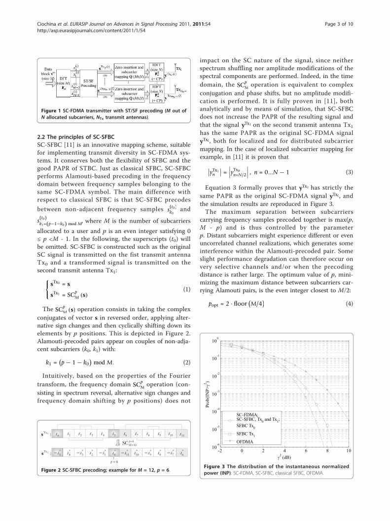
M operation is equivalent to complexconjugation and phase shifts, but no amplitude modifi-cation is performed. It is fully proven in [11], bothanalytically and by means of simulation, that SC-SFBCdoes not increase the PAPR of the resulting signal andthat the signal yTx1 on the second transmit antenna Tx1has the same PAPR as the original SC-FDMA signalyTx0, both for localized and for distributed subcarriermapping. In the case of localized subcarrier mapping forexample, in [11] it is proven that
∣∣yTx1n
∣∣ = ∣∣∣yTx0n+N/2
∣∣∣ , n = 0...N − 1 (3)
Equation 3 formally proves that yTx1 has strictly thesame PAPR as the original SC-FDMA signal yTx0, andthe simulation results are reproduced in Figure 3.The maximum separation between subcarriers
carrying frequency samples precoded together is max(p,M - p) and is thus controlled by the parameterp. Distant subcarriers might experience different or evenuncorrelated channel realizations, which generates someinterference within the Alamouti-precoded pair. Someslight performance degradation can therefore occur onvery selective channels and/or when the precodingdistance is rather large. The optimum value of p, mini-mizing the maximum distance between subcarriers car-rying Alamouti pairs, is the even integer closest to M/2:
popt = 2 · floor (M/4)
(4)
Figure 1 SC-FDMA transmitter with ST/SF precoding (M out ofN allocated subcarriers, NTx transmit antennas).
0Tx :s
1Tx :s
612SC p
M
6p
*0s
*3s
*1s
*2s
*4s
*5s
*6s
*7s
*8s
*9s
*10s
*11s
3s1s 2s 4s 5s 6s 7s0s 8s 9s 10s 11s
Figure 2 SC-SFBC precoding; example for M = 12, p = 6.
-2 0 2 4 6 8 1010
-6
10-5
10-4
10-3
10-2
10-1
100
2 (dB)
Prob
(IN
P>2 )
SC-FDMA;SC-SFBC, Tx0 and Tx1;SFBC Tx0
SFBC Tx1
OFDMA
Figure 3 The distribution of the instantaneous normalizedpower (INP): SC-FDMA, SC-SFBC, classical SFBC, OFDMA.
Ciochina et al. EURASIP Journal on Advances in Signal Processing 2011, 2011:54http://asp.eurasipjournals.com/content/2011/1/54
Page 3 of 10

SC-SFBC can benefit from low-complexity frequency-domain decoding. Indeed, couples of subcarriers (k0,k1)carrying Alamouti pairs can be identified and separatelydecoded. To minimize the impact of the interferencecreated within the Alamouti pair by precoding onto dis-tant subcarriers, minimum mean square error (MMSE)is employed instead of the maximum ratio combiningusually employed in Alamouti decoding. MMSE decod-ing remains low-complexity (inversion of one order-2matrix for each of the M/2 Alamouti pairs in one SC-FDMA symbol).
3. Multi-user SC-SFBCSo far, the study reviewed in the previous sectionconcentrated on transmit diversity techniques forSU-MIMO transmission, where each mobile station(MS) uses its transmit antennas to improve the perfor-mance at a given throughput, making use of the avail-able spatial diversity. Let us now introduce theprinciples of SC-SFBC in a MU-MIMO scenario.
3.1 Extending SC-SFBC to MU transmissionWe consider that several users, each user having an MSequipped with two transmit antennas, are managed bythe same base station (BS). The BS tries to optimallymap the uplink signals of these users in a given limitedbandwidth. Each such user implements SC-SFBC as atransmit diversity scheme. According to the desiredthroughput, to the capabilities of each MS and to thecorresponding channel quality, the scheduler at the BSwill decide the modulation and coding scheme (MCS)and the spectral allocation of each user. To optimize thespectral occupancy and increase the throughput, it isinteresting to allow some spectral reuse between usershaving either the same or different overlapping allocatedbandwidths.Let us assume that the scheduler allows two users
(MS0 and MS1) to share some (or all) of the subcarriersallocated to each user. Each user is employing transmitdiversity techniques, e.g., SC-SFBC, and there is somespectral overlapping between users. More clearly, theMU-MIMO scheme used here combines spatial multi-plexing with SC-SFBC. This is depicted in Figure 4. TheMU-MIMO channel has NTX = NTX + NTX = 4 transmitantennas (two antennas for each of the two user). Atleast two receive antennas are needed at the BS to sepa-rate the two users.At the scheduler, the number of subcarriers Mi, as
well as the starting position ni of the portion of spec-trum allocated to each MSi, is computed. When SC-SFBC is used, Equation 4 shows that, to minimize themaximum distance between subcarriers coded together,
the best strategy is to employ SC p=2floor(M/4)M
. For
simplification, let us consider in the following that M isa multiple of 4 and thus popt = M/2. In an MU-MIMOcontext, double SC-SFBC might have some pairingincompatibility problems. Indeed, let us analyze thesituation depicted in Figure 5, where MS0 is allocatedM0 = 8 subcarriers and MS1 is allocated M1 = 12 sub-carriers. The portions of spectrum occupied by the twoMSs start with the same spectral position n0 = n1 = 0,which means that the first occupied subcarrier by eachMS is the one with index 0, denoted as f0 in Figure 5.Therefore, MS0 should use SC 4
8 and MS1 should useSC 6
12. Subcarriers with indexes (k0, k1) obtained byapplying Equation 2 contain Alamouti pairs. Each MSuses its optimum p parameter, respectively, p0 = 4 and p1= 6 in this example. On the fifth occupied subcarrier f4 forexample, MS0 transmits frequency samples s4 and −s∗7onto its two transmit antennas, respectively. Next, f4 ispaired with f7, onto which MS0 transmits frequency sam-ples s7 and s∗4, respectively. On the same subcarrier f4, MS1transmits frequency samples s′4 and−s′∗1, respectively, onto
Figure 4 MU-MIMO SC-SFBC: two users with spectraloverlapping.
0Txs 1Txs 2Txs 3Txs
3 :f
1 :f2 :f
4 :f5 :f6 :f7 :f
0 :f
8 :f9 :f
10 :f11 :f
*0s
*3s
*1s
*2s
*4s
*6s
*7s
*5s
3s
1s2s
4s5s6s7s
0s
*0s
*3s
*1s
*2s
*4s
*6s
*7s
*5s
*10s
*8s
*9s
*11s
3s
1s2s
4s5s6s7s
0s
8s9s
10s11s
0
0
/2SCMM
1
1
/2SCMM
Figure 5 MU double SC-SFBC with incompatible pairing ofsubcarriers; example for M0 = 8, p0 = 4, M1 = 12, p 1 = 6.
Ciochina et al. EURASIP Journal on Advances in Signal Processing 2011, 2011:54http://asp.eurasipjournals.com/content/2011/1/54
Page 4 of 10

its two transmit antennas. Since MS1 uses SC 612, f4 is
paired with f1. As a result, the pairing of subcarriers is notcompatible between MS0 and MS1. Because of this incom-patibility, this structure does not correspond to a doubleSC-SFBC construction and the conventional MMSE sim-plified detector cannot be employed anymore.A joint MMSE detection over all the bandwidth con-
taining cross-codes subcarriers is necessary in this case.For the example in Figure 5, this would involve invert-ing a matrix of order M0 + M1 = 20 instead of twomatrices of order 4 and two matrices of order 2, as itwould have been the case if the two MS were correctlyaligned to form double Alamouti pairs on the overlap-ping subcarriers, and simple Alamouti pairs on theremaining subcarriers. The problem becomes even morecomplex when three or more users have overlappingsubcarriers. This complexity issue is a real problem inpractice. Since the number of subcarriers allocated toeach user is variable, and the number of users havingpartially overlapping transmission bandwidths with oneanother may be more than 2, the receiver must bedimensioned for the worst-case scenario and should beable to invert matrices of rank hundreds or thousands.For an LTE transmission in the 5-MHz bandwidth(using 300 data carriers for example), the receivershould be dimensioned so as to be able to invertmatrices of order 600.
3.2 Parameter optimizationTo show how this incompatibility problem can beavoided, let us notice that any SCp
M operation can be
seen as the concatenation of SC0p and SC0
M−p operations,applied onto the first p and, respectively, the last M - psamples of the input vector:
SCpM
([s0...sM−1
])=
[SC0
p
([s0...sp−1
]), SC0
M−p
([sp...sM−1
])](5)
This is a direct result of the very structure of SC-SFBC. Indeed, in the example in Figure 2, we noticethat sTx1 = SC6
12
(sTx0
)while the first (respectively last)
six frequency samples of sTx1 respect the relationship:⎧⎪⎨⎪⎩
[sTx10 ...sTx1p−1=5
]= SC0
p=6
([sTx00 ...sTx0p−1=5
])[sTx1p=6...s
Tx1M−1=11
]= SC0
M−p=6
([sTx0p=6...s
Tx0M−1=11
]) (6)
Let us denote the number of subcarriers simulta-neously used by two MSs by Moverlap. To avoid any pair-ing incompatibility, the two MSs need to transmit thesame symbol structure over the overlapping spectralportion. Based on the property stated above, when thetwo MSs have strictly different spectral allocations, theonly valid option is to chose p parameters pi and
spectrum positions ni such that the overlapping portion
has a structure based on SC0Moverlap
. While an optimiza-
tion of parameter p has no direct impact on the allo-cated set of subcarriers, an optimization of the spectrumpositions ni limits the flexibility of the frequencyscheduler.The case where the two MSs have the same number
of allocated subcarriers M0 = M1 and share the samebandwidth is trivial since no pairing incompatibilityarises. Pairs of subcarriers (k0,k1) carrying double Ala-mouti pairs can be identified and low-complexityMMSE decoding can be applied (involving M/2 order-4matrix inversions). We only treat here of the case ofdifferent spectral allocation M0 ≠ M1, let us assume forexample M0 <M1. The case of users with the samenumber of allocated subcarriers M0 = M1 but differentallocated bands n0 ≠ n1 can be treated in a similarmanner.For n0 = n1, a solution is given in Figure 6. We need
to impose MS0 to use SCp0=0M0
and MS1 to use SCp1=M0M1
.
The SCp1=M0M1
can be seen as the concatenation of two
SC-like operations
• SC0M0
to match the configuration of MS0; on thispart of the spectrum, double SC-SFBC transmissioncan thus be employed;• The remaining SC0
M1−M0corresponds to a simple
SC-SFBC transmission and keeps an overall SC-typesignal to be transmitted by MS1.
Hence, it is no longer possible to use a default valuefor the p parameter for all the system (highest even inte-ger inferior to half of the respective number of allocated
0Txs 1Txs 2Txs 3Txs
3 :f
1 :f2 :f
4 :f5 :f6 :f7 :f
0 :f
8 :f9 :f
10 :f11 :f
*0s
*3s
*1s
*2s
*4s
*6s
*7s
*5s
3s
1s2s
4s5s6s7s
0s
*0s
*3s
*1s
*2s
*4s
*6s
*7s
*5s
*10s
*8s
*9s
*11s
3s
1s2s
4s5s6s7s
0s
8s9s
10s11s
0
0SCM 0
0SCM
1 0
0SCM M
0
1SCM
M
Figure 6 MU double SC-SFBC M0 <M1, an example for M0 = 8,M1 = 12, p0 = 0, p1 = 8, n0 = n1.
Ciochina et al. EURASIP Journal on Advances in Signal Processing 2011, 2011:54http://asp.eurasipjournals.com/content/2011/1/54
Page 5 of 10

subcarriers), but double SC-SFBC structure is kept atthe expense of a modification of the p parameter, i.e.,some performance degradation as the maximum dis-tance between subcarriers that are jointly precoded isincreased. But, complexity is strongly reduced: only twomatrices of order 4 and two matrices of order 2 need tobe inverted during MMSE decoding for the example inFigure 6, while for the structure in Figure 5 an inversionof an order-20 matrix was required. It should also benoted that additional signaling is necessary to indicatethe values of p to be used by each MS in this case.An alternative solution for the case when the spectral
bands allocated to the two MSs do not have the samespectral starting position is to decompose SC p1
M1into
SC 0p1 and SC 0
M1−p1, and to allocate MS0 in the middle of
the bandwidth occupied by SC 0p1 if p1 >M0, or in the
middle of the bandwidth occupied by SC 0M1−p1 other-
wise. An example is depicted in Figure 7. Nevertheless,this might lead to a modified double SC-SFBC (there isa sign inversion within the double SC-FDMA pair onantenna Tx3) which needs to be taken into account atthe receiver, without any performance loss. In bothcases depicted in Figures 6 and 7, it is possible to allowdouble SC-SFBC; thanks to an optimization of para-meter p only. No constraint is introduced in the fre-quency scheduler to optimize n0 and n1.
3.3 Optimization of spectral occupancyLet us now extend the particular cases treated in theprevious section to a general framework where a BSmanages several MS, let their number be Nusers. We
propose here to optimize not only the parameter p butalso the spectrum positions ni so as to allow using dou-ble SC-SFBC by several terminals having overlappingspectrum allocations.Depending on the needs and capabilities of uplink
communication of each MS, the BS determines thenumber of subcarriers Mi allocated to each MSi, i = 0...Nusers - 1. Each MS is equipped of at least two transmitantennas. Each MS uses SC-FDMA with SC-SFBC trans-mit diversity for its uplink communication. Our purposeis to schedule these Nusers MSs in such a manner thatthe occupied bandwidth is minimized and the overallthroughput is optimized. The couple (pi, ni), represent-ing the p parameter and the first occupied subcarrier,needs to be determined for each MSi.The main idea behind the solution is to determine two
groups of users, A and B. Spectral bands allocated toeach user do not overlap inside of each group, but eachuser of each group can have overlapping subcarrierswith a maximum of two users from the other group,such as onto the overlapping subcarriers double Ala-mouti pairs are formed.Let subcarrier numbering starting at nA0 = 0; nB0 can
be either null or take another positive value. nA and nB
are auxiliary parameters indicating the index of thefirst available subcarrier in groups A and B, respec-tively. We suppose that BS tries to map Nusers MSs ina bandwidth that is as compact as possible (alterna-tively, it could have one given available bandwidth andwould try to map as many users as possible; algorithmstill stands but the STOP condition needs to be modi-fied). The algorithm presented in the Annex (addi-tional file 1) tries to minimize the number ofsubcarriers allocated to only one single MS to improvethe overall spectral efficiency, while forming doubleSC-SFBC pairs on the subcarriers simultaneously allo-cated to two MSs to ensure low-complexity decoding.The principle of this algorithm is to use the fact thatthe SC operator can be decomposed as shown in Sec-tion 3.2, with the purpose of optimizing the spectraloccupancy. Users are treated one at a time, and ateach step the treated user is allocated a p parametersuch as to share a maximum number of subcarrierswith the previous user by forming “double Alamouti”pairs. STOP condition is attained when all the usershave been scheduled.Let us apply the algorithm in Annex (additional file 1)
for a BS that schedules four MSs with different commu-nication needs, and decides to allocate them, respec-tively, M0 = 12, M1 = 8, M2 = 8, M3 = 4 subcarriersSTART: i = 0, nA0 = 0, nB0 = 0, Nusers = 4nA = nA0 = 0, nB = nA0 + nB0 = 0
0Txs 1Txs 2Txs 3Txs
3 :f
1 :f2 :f
4 :f5 :f6 :f7 :f
0 :f
8 :f9 :f
10 :f11 :f
*0s
*3s
*1s
*2s
*4s
*5s
3s
1s2s
4s5s
0s
*0s
*3s
*1s
*2s
*4s
*6s
*7s
*5s
*10s
*8s
*9s
*11s
3s
1s2s
4s5s6s7s
0s
8s9s
10s11s
0
0SCM
0
1SC p M
M
Figure 7 Double SC-SFBC, M0 <M1, an example for M0 = 6, M1
= 12, p0 = 0, p1 = 8, n0 >n1.
Ciochina et al. EURASIP Journal on Advances in Signal Processing 2011, 2011:54http://asp.eurasipjournals.com/content/2011/1/54
Page 6 of 10

i <Nusers? YES:
Select MS0, determine M0 = 12
nA <nB? NO:
nA = nB? YES:Select MS1, determine M1 = 8
M0 = M1? NO:
n0 = n1 = 0, p0 = M1 = 8, p1 = 0nA = 12, nB = 8, i = 2
i <Nusers? YES:
Select MS2, determine M2 = 8
nA <nB? NO:
nA = nB? NO:M2 >n
A-nB? YESn2 = nB = 8, p2 = nA-nB = 4nB = 16, i = 3
i <Nusers? YES:
Select MS3, determine M3 = 4
nA <nB? YES:
nA = nA0? NO:M3 >n
B-nA? NO:n4 = 12, p4 = 0i = 4
i <Nusers? NO:STOP.The results are depicted in Figure 8. In a similar man-
ner, all the cases depicted in Figures 6 and 7 can bededuced based on this algorithm.Of course, this scheduling strategy directly constrains
the frequency scheduler. However, it should be under-stood that transmit diversity is mainly intended forterminals that cannot benefit from any close-loop pro-cessing as CSI-based frequency scheduling. In otherwords, no frequency scheduling gain can be achievedin this case and the constraint imposed on the fre-quency scheduler is only a specific ordering of eachallocated spectrum, given predetermined spectrumsizes Mi.
4. Simulation resultsLet us consider an SC-FDMA system with N = 512 sub-carriers, among which 300 are active data carriers, to fita bandwidth of 5 MHz. To retrieve frequency diversity,groups of 12 SC-FDMA symbols with QPSK signal map-ping are encoded together with a rate-1/2 turbo codeusing the LTE interleaving pattern [8]. A CP with alength of 36 samples is employed. We consider anuncorrelated Vehicular A MIMO channel with six tapsand a maximum delay spread of 2.51 μs [17]. Localizedsubcarrier mapping and ideal channel estimation areassumed. We employ MMSE detection, with successiveinterference cancelling to reduce the inter-user interfer-ence in the MU-MIMO case.From the discussion in Section 2.2, we can deduce
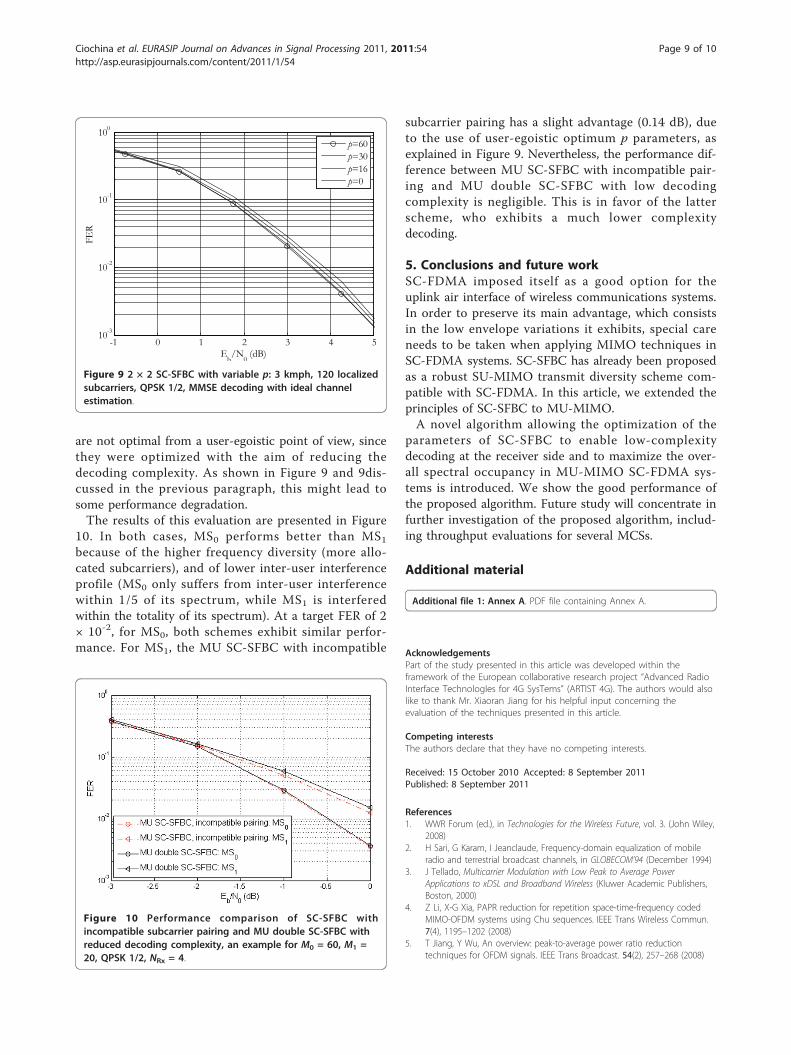
that not using the individual optimum p parameter (4)for the schemes proposed in Section 3 might lead tosome performance degradation. Let us first evaluate theseverity of this degradation in the SU case. Let us con-sider that M = 120 localized subcarriers (coveringaround five times the channel coherence bandwidth) areallocated to a user traveling at 3 kmph, and benefitingfrom perfect channel estimation and MMSE decoding.Figure 9 analyzes how the choice of parameter p influ-ences the performance of SC-SFBC. Performance is eval-uated in terms of frame error rate (FER). p = 60 and p =30, corresponding to p = M/2 and p = M/4, respectively,have similar performance. Employing p = 16 and p = 0leads to a degradation of 0.2 and 0.4 dB, respectively.For vehicular A channel and for the present simulationparameters, the correlation bandwidth Bcoh correspondsto approximately 26 subcarriers. In these conditions,when employing p = 60 and p = 30, about 43% of theAlamouti pairs (26 out of 60 pairs) are situated on sub-carriers having highly correlated fadings. This percen-tage drops to 35 and 21% when choosing p = 16 and p= 0, respectively. This is a worst-case scenario, sinceusers needing to employ transmit diversity are usually inbad propagation conditions and are allocated rathersmall numbers of subcarriers. We can thus concludethat the associated performance degradation due tooptimizing the p parameter as proposed in Sections 3.2and 3.3 is negligible in practice.Let us now investigate the performance of the MU
double SC-SFBC scheme with low decoding complexityproposed in Section 2.2 with respect to the MU SC-SFBC scheme with incompatible subcarrier pairing (e.g.,like in Figure 5). We consider that M0 = 60 and, respec-tively, M1 = 20 localized subcarriers are allocated to twousers and four receive antennas are present at the BS.For the MU double SC-SFBC scheme, the p parameters
Ciochina et al. EURASIP Journal on Advances in Signal Processing 2011, 2011:54http://asp.eurasipjournals.com/content/2011/1/54
Page 7 of 10

Figure 8 MU double SC-SFBC, an example for M0 = 12, M1 = 8, M2 = 8, M3 = 4, p0 = 8, p1 = 0, p2 = 4, p3 = 0, n0 = n1 = 0, n2 = 8, n3 = 12.
Ciochina et al. EURASIP Journal on Advances in Signal Processing 2011, 2011:54http://asp.eurasipjournals.com/content/2011/1/54
Page 8 of 10
are not optimal from a user-egoistic point of view, sincethey were optimized with the aim of reducing thedecoding complexity. As shown in Figure 9 and 9dis-cussed in the previous paragraph, this might lead tosome performance degradation.The results of this evaluation are presented in Figure
10. In both cases, MS0 performs better than MS1because of the higher frequency diversity (more allo-cated subcarriers), and of lower inter-user interferenceprofile (MS0 only suffers from inter-user interferencewithin 1/5 of its spectrum, while MS1 is interferedwithin the totality of its spectrum). At a target FER of 2× 10⁻², for MS0, both schemes exhibit similar perfor-mance. For MS1, the MU SC-SFBC with incompatible
subcarrier pairing has a slight advantage (0.14 dB), dueto the use of user-egoistic optimum p parameters, asexplained in Figure 9. Nevertheless, the performance dif-ference between MU SC-SFBC with incompatible pair-ing and MU double SC-SFBC with low decodingcomplexity is negligible. This is in favor of the latterscheme, who exhibits a much lower complexitydecoding.
5. Conclusions and future workSC-FDMA imposed itself as a good option for theuplink air interface of wireless communications systems.In order to preserve its main advantage, which consistsin the low envelope variations it exhibits, special careneeds to be taken when applying MIMO techniques inSC-FDMA systems. SC-SFBC has already been proposedas a robust SU-MIMO transmit diversity scheme com-patible with SC-FDMA. In this article, we extended theprinciples of SC-SFBC to MU-MIMO.A novel algorithm allowing the optimization of the
parameters of SC-SFBC to enable low-complexitydecoding at the receiver side and to maximize the over-all spectral occupancy in MU-MIMO SC-FDMA sys-tems is introduced. We show the good performance ofthe proposed algorithm. Future study will concentrate infurther investigation of the proposed algorithm, includ-ing throughput evaluations for several MCSs.
Additional material
Additional file 1: Annex A. PDF file containing Annex A.
AcknowledgementsPart of the study presented in this article was developed within theframework of the European collaborative research project “Advanced RadioInterface TechnologIes for 4G SysTems” (ARTIST 4G). The authors would alsolike to thank Mr. Xiaoran Jiang for his helpful input concerning theevaluation of the techniques presented in this article.
Competing interestsThe authors declare that they have no competing interests.
Received: 15 October 2010 Accepted: 8 September 2011Published: 8 September 2011
References1. WWR Forum (ed.), in Technologies for the Wireless Future, vol. 3. (John Wiley,
2008)2. H Sari, G Karam, I Jeanclaude, Frequency-domain equalization of mobile
radio and terrestrial broadcast channels, in GLOBECOM’94 (December 1994)3. J Tellado, Multicarrier Modulation with Low Peak to Average Power
Applications to xDSL and Broadband Wireless (Kluwer Academic Publishers,Boston, 2000)
4. Z Li, X-G Xia, PAPR reduction for repetition space-time-frequency codedMIMO-OFDM systems using Chu sequences. IEEE Trans Wireless Commun.7(4), 1195–1202 (2008)
5. T Jiang, Y Wu, An overview: peak-to-average power ratio reductiontechniques for OFDM signals. IEEE Trans Broadcast. 54(2), 257–268 (2008)
-1 0 1 2 3 4 510-3
10-2
10-1
100
Eb/N
0 (dB)
FER
p=60p=30p=16p=0
Figure 9 2 × 2 SC-SFBC with variable p: 3 kmph, 120 localizedsubcarriers, QPSK 1/2, MMSE decoding with ideal channelestimation.
Figure 10 Performance comparison of SC-SFBC withincompatible subcarrier pairing and MU double SC-SFBC withreduced decoding complexity, an example for M0 = 60, M1 =20, QPSK 1/2, NRx = 4.
Ciochina et al. EURASIP Journal on Advances in Signal Processing 2011, 2011:54http://asp.eurasipjournals.com/content/2011/1/54
Page 9 of 10

6. H Ochai, H Imai, Performance of the deliberate clipping with adaptivesymbol selection for strictly band-limited OFDM systems. IEEE J Sel AreasCommun. 18(11), 2270–2277 (2000). doi:10.1109/49.895032
7. C Ciochina, F Buda, H Sari, An analysis of OFDM peak power reductiontechniques for WiMAX systems, in ICC’06, (Istanbul, Turkey, June 2006)
8. 3rd Generation Partnership Project; Technical Specification Group RadioAccess Network; Evolved Universal Terrestrial Radio Access (E-UTRA),“Physical Channels and Modulation (Release 9)”. 3GPP TS 36.211 V9.1.0(March 2010)
9. HG Myung, J Lim, DJ Goodman, Single carrier FDMA for uplink wirelesstransmission. IEEE Veh Technol Mag. 3(1), 30–38 (2006)
10. HG Myung, J Lim, DJ Goodman, Peak-to-average power ratio of singlecarrier FDMA signals with pulse shaping, in 17th Annual IEEE InternationalSymposium on Personal, Indoor and Mobile Radio Communications(PIMRC’06), (Helsinki, Finland, September 2006)
11. C Ciochina, D Castelain, D Mottier, H Sari, New PAPR-preserving mappingmethods for single-carrier FDMA with space-frequency block codes. IEEETrans Wirel Commun. 8(10), 5176–5186 (2009)
12. SM Alamouti, A simple transmit diversity technique for wirelesscommunications. IEEE J Sel Areas Commun. 16(8), 1451–1458 (1998).doi:10.1109/49.730453
13. D Tse, P Viswanath, Fundamentals of Wireless Communication (CambridgeUniversity Press, Cambridge, 2005)
14. Z Wang, G Giannakis, Wireless multicarrier communications. Signal ProcessMag IEEE. 17(3), 29–48 (2000). doi:10.1109/79.841722
15. 3rd Generation Partnership Project; Technical Specification Group RadioAccess Network; Evolved Universal Terrestrial Radio Access (E-UTRA),“Multiplexing and Channel Coding (Release 10)”. 3GPP TS 36.212 V10.1.10(March 2011)
16. 3rd Generation Partnership Project, RAN1, Performance Evaluations ofSTBC/SFBC Schemes in E-UTRA Uplink, R1-063179, Alcatel
17. 3GPP TR 25.996 V7.0.0 (2007-06), Spatial channel model for Multiple InputMultiple Output (MIMO) simulations
doi:10.1186/1687-6180-2011-54Cite this article as: Ciochina et al.: Low PAPR space frequency blockcoding for multiuser MIMO SC-FDMA systems: specific issues for userswith different spectral allocations. EURASIP Journal on Advances in SignalProcessing 2011 2011:54.
Submit your manuscript to a journal and benefi t from:
7 Convenient online submission
7 Rigorous peer review
7 Immediate publication on acceptance
7 Open access: articles freely available online
7 High visibility within the fi eld
7 Retaining the copyright to your article
Submit your next manuscript at 7 springeropen.com
Ciochina et al. EURASIP Journal on Advances in Signal Processing 2011, 2011:54http://asp.eurasipjournals.com/content/2011/1/54
Page 10 of 10