Embed Size (px)
Citation preview
10 Journal of Engineering and Architecture, Vol. 1 No. 2, December 2013
©American Research Institute for Policy Development www.aripd.org/jea
PAPR Reduction with Wavelet Transform and Different PAPR Reduction Tecniques in MIMO-OFDM Systems
ÖĞR.GÖR. MURAT TÖREN1
Abstract A new technique which is Wavelet transform based, is investigated in order to decrase the major drawback of MIMO-OFDM systems ( Multiple Input-Multiple Output-Ortogonal Frequency Division Multiplexing) is the high peak-to-average-power ratio (PAPR).SLM (Selective Mapping ) and PTS (Partial Transmiting Sequence) tecniques are applied in order to decrase PAPR in MIMO-OFDM systems. SLM and PTS tecniques are transmitted most powerful signal.In this study, SLM and PTS techniques are used that assures reduction on PAPR . In the system, Wavelet transform is used instead of Fourier transform and a new tecnique is proposed to reduce PAPR at a rate of 20 percent
Keywords: MIMO (Multiple input-multiple output), OFDM (Ortogonal frequency division multiplexing), SLM(selective mapping), PTS(partial transmitting sequence), PAPR(peak-to average-power ratio), WT(Wavelet transform).
1.Introductıon Wireless communication systems need high data rate, secure communication and band width
efficiency. In order to corresppond these needs, OFDM systems is a suggested techniques in the frequency selective fading bands[1].
OFDM systems has advantages such as high rate transmission rate band width gain. Moreover,
OFDM system ensures countless paralel narrow bands and it could be used with MIMO systems so that transmitted data rate, diversity earning and system capasity are raised[2,3].
In this study, MIMO-OFDM systems are assesed as the key technology for high data rate
communication and it could be used in DSL, IEEE802.11, IEEE802.16 and IEEE 802.15.3a and 4G technology and satelitte link[4].
There are also disadvantages of MIMO-OFDM systems. The most important disadvantages of
these systems is PAPR and many solutions are suggested in order to solve[5-7]. These techniques could be categorited into two subcategories. In the first category, clipping and
peak windowing are listed. For example, clipping technique is the most basic tecnique to reduce PAPR. But, this tecnique corrupts the sign because of propagation and interference[8].
1 T.C.RECEP TAYYİP ERDOĞAN ÜNİVERSİTESİ, TEKNİK BİLİMLER MYO, ELEKTRONİK TEKN. BÖLÜMÜ
Journal of Engineering and Architecture, Vol. 1 No. 2, December 2013 11
©American Research Institute for Policy Development www.aripd.org/jea
In the second category, interference techniques are listed. Among these tecniques, using block coding technique PAPR and data rate reduce[9], but signal energy increases. In this study, PAPR reduce tecniques and SLM[10], and PTS [17,19] are applied on MIMO-OFDM system. In order to reduce PAPR, simulation studies are conducted by DWT blocks are added instead of FFT blocks into the MIMO-OFDM system.
This study explores the results of the manipulation of the number of subblock and the number of
sub-carrier ,which are important in SLM techniques and for the two parameters, %20 reduce of PAPR value is obtained.
Moreover, %20 reduce of the number of subblock and different phase values in the PTS
tecnique are obtained. 2. Mımo-Ofdm Systems And Papr
Mostly used MIMO-OFDM systems are the systems combination of MIMO and OFDM, which
is modulation of multiplxing.MIMO structure of this system has an advantages that is obtained by discrimination of spatıal satellites in multiple propagation enviroment. MIMO systems occurs in both transmıtter and receiver side of satellite sequences.Bunun amacı işaretlerin düzgün iletilip karşı taraftan alınmasında birçok alıcı tarafından algılanması önerisine dayanmaktadır
This is based on the regular symbols are which detected by many receiver [13,14].MIMO
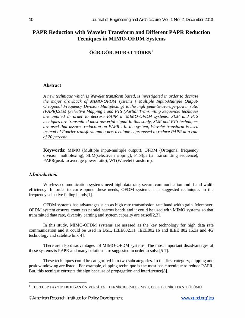
system is a significant technique that overcomes diversity gain and sembol fadings. Combining this tecnique and OFDM modulation system, performance is tried to increase with the system shown in Graph1.
Şekil 1. MIMO-OFDM Blok Diyagramı Denoting the signs that will be transmit in the OFDM system, In the data block with the length
N, k subcarrier data block is established as [2]: Corresponding all sub-carriers. 푋 = (푋 ,푋 , … … ,푋 ) (1)
12 Journal of Engineering and Architecture, Vol. 1 No. 2, December 2013
©American Research Institute for Policy Development www.aripd.org/jea
All 푋 modulate in frequency range of the subcarrier 푓 (푘 = 0, … … ,푁 − 1), if 푓 = 푘∆푓 then N sub data blocks are ortogonal. Here, 푓 = .. and T is the period of OFDM[11].
Complex base band OFDM sign x(t) is denoted :
푥(푡) =√∑ 푋 푒 , tϵ[0,T] (2)
X complex symbols are transmitted x=[x0, x1,……….., xN-1]. 푥 = 퐼퐷퐹푇(푋) (3) All sub-carriers of these transmitted signs are statictical independent so that sign samples
complex gaussian distribution and high amplitude in the time dimension[11]. High amplitude value in the OFDM systems creates a disadvantege PAPR value in x(t) symbol
of OFDM system.
푃퐴푃푅{푥(푡)} = | ( )|{| ( ) |} (4)
E[.] is a expectation operation. If PAPR is denoted as distributed time
푥(푛) =√∑ 푋 푒 , n=0,…., N-1 (5)
Here, L is oversampling factor. İf QL is an IDFT matrix with NL dimension and L scale,
equation (3) can be written as:
푥 = 푄 (푋) (6) In this situation, PAPR can be written as:
푃퐴푃푅{푥} = | ( )|{| | } (7)
Since PAPR can have random variable value, it can be denoted as complementary cumulatif
distribution function:CCDF When CCDF, PAPR0 threshold is exceed, PAPR value of OFDM sign can be expressed as: CCDF(PAPR(x(n)))=Pr(PAPR(x(n)))>PAPR0 (8) Depending to the independent N data block, SISO OFDM in the sign PAPR CCDF can be
denoted as the following: 푃 = 푃 푃퐴푃푅 푥(푛) > 푃퐴푃푅 = 1 − (1 − 푒 ) (9) If this equation is composed for MIMO-OFDM system, PAPR value on the i.th transmitted
satelitte , PAPRi is : 푃 (푃퐴푃푅 > 푃퐴푃푅 ) = 1 − (1 − 푒 ) (10)
şeklindedir. Burada MtN. Here, MtN is the number of the samples on time plane (platform). With the literature support,
looking at the PAPR values of SISO-OFDM and MIMO-OFDM systems, MIMO-OFDM systems has better performance[11].
Journal of Engineering and Architecture, Vol. 1 No. 2, December 2013 13
©American Research Institute for Policy Development www.aripd.org/jea
3. Papr Reductıon Tecnıques
3.1. Selective Mapping (SLM) and Partial Transmiting Sequence (PTS) Tecnıques: In this study there are many tecniques are used to reduce PAPR for PAPR reduction in
MIMO-OFDM systems. These are clipping, coding, selective mapping(SLM) ,partial transmitting sequence
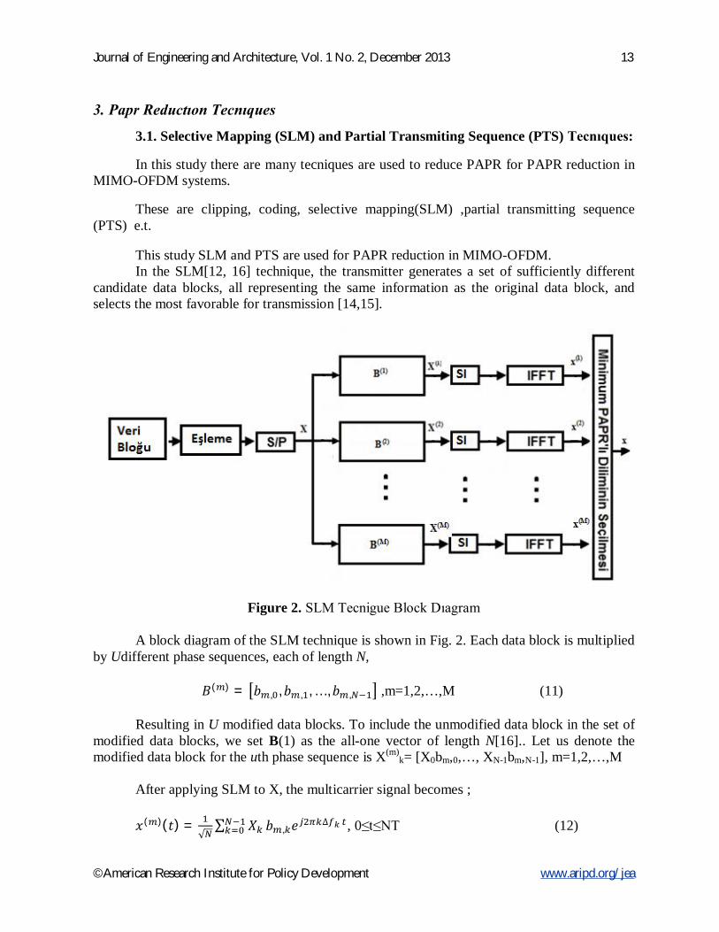
(PTS) e.t. This study SLM and PTS are used for PAPR reduction in MIMO-OFDM. In the SLM[12, 16] technique, the transmitter generates a set of sufficiently different
candidate data blocks, all representing the same information as the original data block, and selects the most favorable for transmission [14,15].
Figure 2. SLM Tecnigue Block Dıagram A block diagram of the SLM technique is shown in Fig. 2. Each data block is multiplied
by Udifferent phase sequences, each of length N,
퐵( ) = 푏 , ,푏 , , … ,푏 , ,m=1,2,…,M (11) Resulting in U modified data blocks. To include the unmodified data block in the set of
modified data blocks, we set B(1) as the all-one vector of length N[16].. Let us denote the modified data block for the uth phase sequence is X(m)
k= [X0bm,0,…, XN-1bm,N-1], m=1,2,…,M
After applying SLM to X, the multicarrier signal becomes ; 푥( )(푡) =
√∑ 푋 푏 , 푒 ∆ , 0≤t≤NT (12)
14 Journal of Engineering and Architecture, Vol. 1 No. 2, December 2013
©American Research Institute for Policy Development www.aripd.org/jea
Among the modified data blocks X(u), u = 1, 2,…, U, the one with the lowest PAPR is selected for transmission. Information about the selected phase sequence should be transmitted to the receiver as side information. At the receiver, the reverse operation is performed to recover the original data block. For implementation, the SLM technique needs U IDFT operations, and the number of required side information bits is log2M for each data block. This approach is applicable with all types of modulation and any number of subcarriers. The amount of PAPR reduction for SLM depends on the number of phase sequences U and the design of the phase sequences. In [32] an SLM technique without explicit side information is proposed.
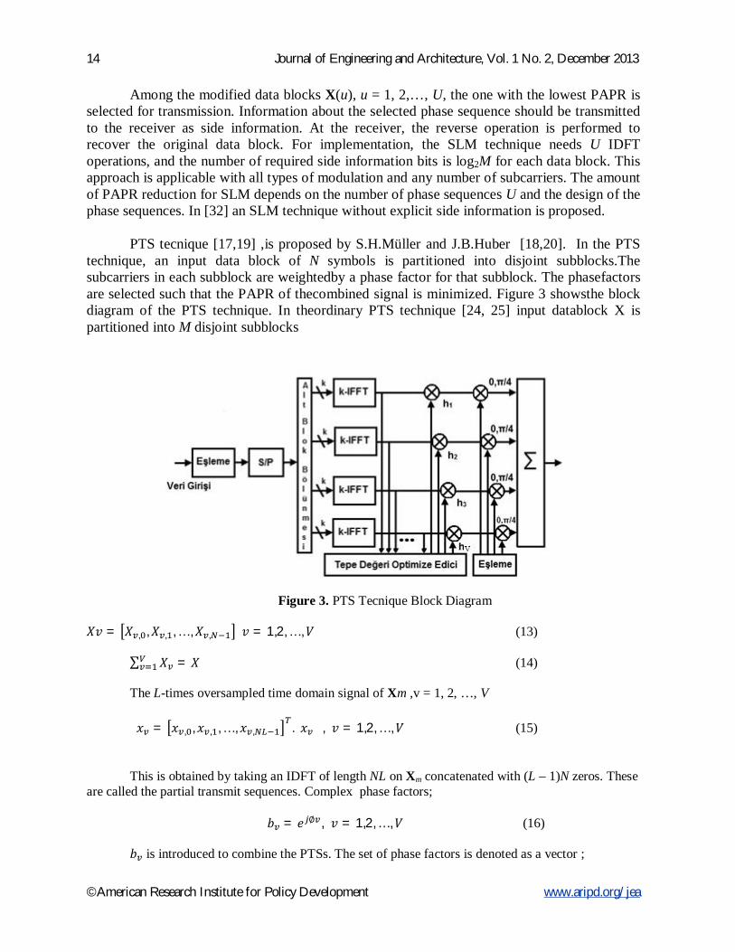
PTS tecnique [17,19] ,is proposed by S.H.Müller and J.B.Huber [18,20]. In the PTS
technique, an input data block of N symbols is partitioned into disjoint subblocks.The subcarriers in each subblock are weightedby a phase factor for that subblock. The phasefactors are selected such that the PAPR of thecombined signal is minimized. Figure 3 showsthe block diagram of the PTS technique. In theordinary PTS technique [24, 25] input datablock X is partitioned into M disjoint subblocks
Figure 3. PTS Tecnique Block Diagram
푋푣 = 푋 , ,푋 , , … ,푋 , 푣 = 1,2, … ,푉 (13) ∑ 푋 = 푋 (14) The L-times oversampled time domain signal of Xm ,v = 1, 2, …, V 푥 = 푥 , , 푥 , , … , 푥 , . 푥 , 푣 = 1,2, … ,푉 (15)
This is obtained by taking an IDFT of length NL on Xm concatenated with (L – 1)N zeros. These are called the partial transmit sequences. Complex phase factors;
푏 = 푒 ∅ , 푣 = 1,2, … ,푉 (16)
푏 is introduced to combine the PTSs. The set of phase factors is denoted as a vector ;
Journal of Engineering and Architecture, Vol. 1 No. 2, December 2013 15
©American Research Institute for Policy Development www.aripd.org/jea
푏 = [푏 , 푏 , … , 푏 ] (17)
The time domain signal after combining is given by; 푥′(푏) = ∑ 푏 .푥 (18) Where; 푥′(푏) = 푥 ′(푏), 푥 ′(푏), … , 푥 ′(푏) dir. The objective is to find the set of phase factors that minimizes the PAPR. Minimization of
PAPR is related to the minimization of
푚푎푥 푥′(푏) | (19) In general, the selection of the phase factors is limited to a set with a finite number of elements
to reduce the search complexity. The set of allowed phase factors is written as 푃 = 푒 / |푙 = 0,1, … ,푊 − 1 (20) where W is the number of allowed phase factors. In addition, we can set b1= 1 without any loss
of performance. So, we should perform an exhaustive search for (M – 1) phase factors. Hence, WM–1 sets of phase
factorsare searched to find the optimum set of phasefactors. The search complexity increases exponentiallywith the number of subblocks M. PTS needs M IDFT operations for each data block, and the number of required side information bits is log2Wm–1, where [y] denotes the smallest integer that does not exceed y. The amount of PAPR reduction depends on the number of subblocks M and the number of allowed phase factorsW. This study is used this parameters. 4. Wavelet Transform (Wt)
In this study, WT is preferred to use instead of FFT block. The reason is that FFT block has results only on the frequency platform for incoming signs, however, DWT has result fort he sign as well as fort he frequency platform. . In more resolutıon analysis of WT, h[m] and g[m] factors enable representing wavelet and scaling functions. H[m] is related with wavelet function, gm is related with scaling functions. While signs obtain on the receiver side, these filters are used. So, WT can be easily applied using discrete time filters[2]. Here is the matematical notation of WT:
휓 , [ ] = √2 ∑ ℎ[푚′]′ 휓 , ′ (21) 휓 , [ ] = √2 ∑ 푔[푚′]′ 휓 , ′ (22) 휓 , [ ] is the pth wavelet package function on the kth platform[21]. when sign has transformed with IDWT Instead of IFFT, transformed sign is denoted : 푥 = 퐼퐷푊푇(푋) (23) 푥(푡) = ∑ ∑ 푋(푙)휓 , (푡 − 푙푁)∞ (24)
16 Journal of Engineering and Architecture, Vol. 1 No. 2, December 2013
©American Research Institute for Policy Development www.aripd.org/jea
P, l represent location data indexes, 휓 , represents the wavelet package function for pth subchannel, and X(l) represents data signs.
5. Sımulatıon Results
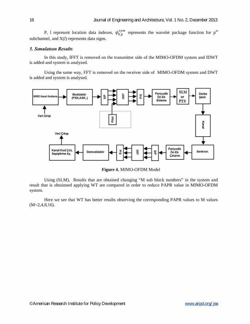
In this study, IFFT is removed on the transmitter side of the MIMO-OFDM system and IDWT is added and system is analyzed.
Using the same way, FFT is removed on the receiver side of MIMO-OFDM system and DWT
is added and system is analysed.
Figure 4. MIMO-OFDM Model Using (SLM), Results that are obtained changing “M sub block numbers” in the system and
result that is obtainned applying WT are compared in order to reduce PAPR value in MIMO-OFDM system.
Here we see that WT has better results observing the corresponding PAPR values to M values
(M=2,4,8,16).
Journal of Engineering and Architecture, Vol. 1 No. 2, December 2013 17
©American Research Institute for Policy Development www.aripd.org/jea
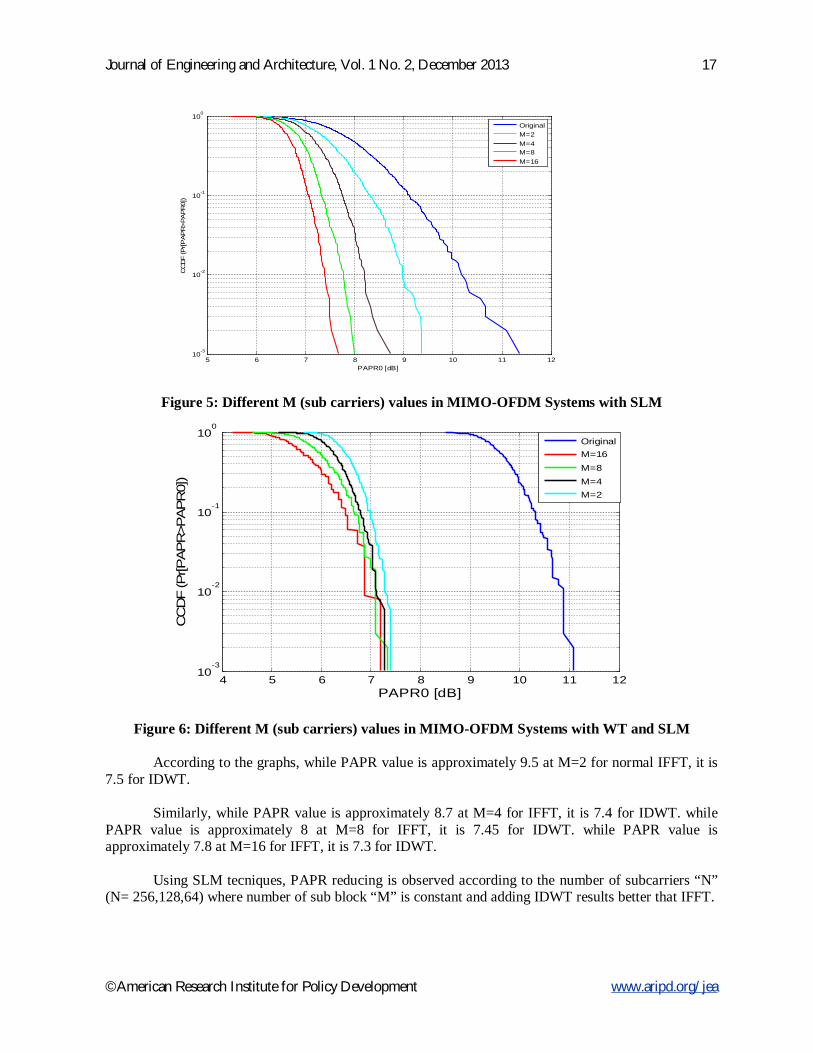
Figure 5: Different M (sub carriers) values in MIMO-OFDM Systems with SLM
Figure 6: Different M (sub carriers) values in MIMO-OFDM Systems with WT and SLM
According to the graphs, while PAPR value is approximately 9.5 at M=2 for normal IFFT, it is 7.5 for IDWT.
Similarly, while PAPR value is approximately 8.7 at M=4 for IFFT, it is 7.4 for IDWT. while
PAPR value is approximately 8 at M=8 for IFFT, it is 7.45 for IDWT. while PAPR value is approximately 7.8 at M=16 for IFFT, it is 7.3 for IDWT.
Using SLM tecniques, PAPR reducing is observed according to the number of subcarriers “N”
(N= 256,128,64) where number of sub block “M” is constant and adding IDWT results better that IFFT.
5 6 7 8 9 10 11 1210-3
10-2
10-1
100
PAPR0 [dB]
CC
DF (P
r[PAP
R>PA
PR0]
)
OriginalM=2M=4M=8M=16
4 5 6 7 8 9 10 11 1210
-3
10-2
10-1
100
PAPR0 [dB]
CC
DF
(Pr[P
AP
R>P
APR
0])
OriginalM=16M=8M=4M=2
18 Journal of Engineering and Architecture, Vol. 1 No. 2, December 2013
©American Research Institute for Policy Development www.aripd.org/jea
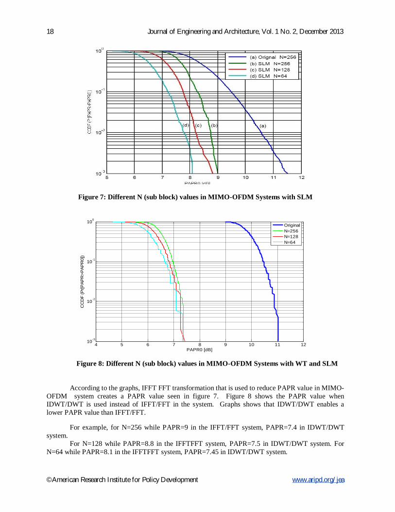
Figure 7: Different N (sub block) values in MIMO-OFDM Systems with SLM
Figure 8: Different N (sub block) values in MIMO-OFDM Systems with WT and SLM
According to the graphs, IFFT FFT transformation that is used to reduce PAPR value in MIMO-
OFDM system creates a PAPR value seen in figure 7. Figure 8 shows the PAPR value when IDWT/DWT is used instead of IFFT/FFT in the system. Graphs shows that IDWT/DWT enables a lower PAPR value than IFFT/FFT.
For example, for N=256 while PAPR=9 in the IFFT/FFT system, PAPR=7.4 in IDWT/DWT
system. For N=128 while PAPR=8.8 in the IFFTFFT system, PAPR=7.5 in IDWT/DWT system. For
N=64 while PAPR=8.1 in the IFFTFFT system, PAPR=7.45 in IDWT/DWT system.
4 5 6 7 8 9 10 11 1210-3
10-2
10-1
100
PAPR0 [dB]
CC
DF
(Pr[P
AP
R>P
AP
R0]
)
OriginalN=256N=128N=64
Journal of Engineering and Architecture, Vol. 1 No. 2, December 2013 19
©American Research Institute for Policy Development www.aripd.org/jea
Using (PTS), Results that are obtained changing “V sub block numbers” in the system and result that is obtainned applying WT are compared in order to reduce PAPR value in MIMO-OFDM system.
Here we see that WT has better results observing the corresponding PAPR values to V values
(V=2,4).
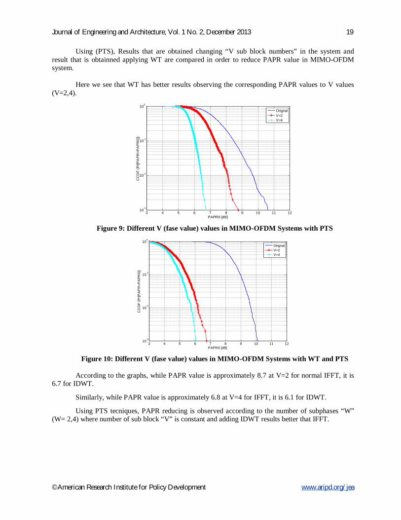
Figure 9: Different V (fase value) values in MIMO-OFDM Systems with PTS
Figure 10: Different V (fase value) values in MIMO-OFDM Systems with WT and PTS
According to the graphs, while PAPR value is approximately 8.7 at V=2 for normal IFFT, it is
6.7 for IDWT.
Similarly, while PAPR value is approximately 6.8 at V=4 for IFFT, it is 6.1 for IDWT.
Using PTS tecniques, PAPR reducing is observed according to the number of subphases “W” (W= 2,4) where number of sub block “V” is constant and adding IDWT results better that IFFT.
3 4 5 6 7 8 9 10 11 1210-3
10-2
10-1
100
PAPR0 [dB]
CC
DF
(Pr[P
AP
R>P
AP
R0]
)
OrignalV=2V=4
3 4 5 6 7 8 9 10 11 1210
-3
10-2
10-1
100
PAPR0 [dB]
CC
DF
(Pr[P
AP
R>P
AP
R0]
)
OrignalV=2V=4
20 Journal of Engineering and Architecture, Vol. 1 No. 2, December 2013
©American Research Institute for Policy Development www.aripd.org/jea
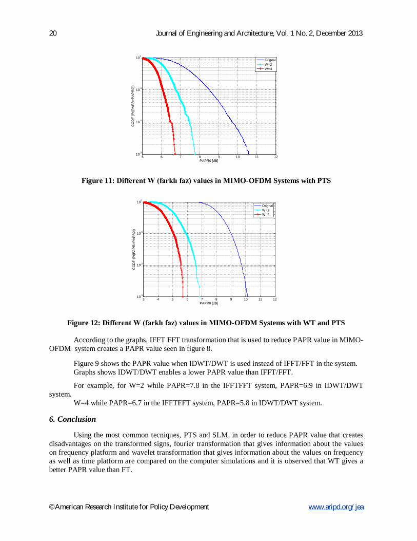
Figure 11: Different W (farklı faz) values in MIMO-OFDM Systems with PTS
Figure 12: Different W (farklı faz) values in MIMO-OFDM Systems with WT and PTS According to the graphs, IFFT FFT transformation that is used to reduce PAPR value in MIMO-
OFDM system creates a PAPR value seen in figure 8. Figure 9 shows the PAPR value when IDWT/DWT is used instead of IFFT/FFT in the system. Graphs shows IDWT/DWT enables a lower PAPR value than IFFT/FFT.
For example, for W=2 while PAPR=7.8 in the IFFTFFT system, PAPR=6.9 in IDWT/DWT system.
W=4 while PAPR=6.7 in the IFFTFFT system, PAPR=5.8 in IDWT/DWT system.
6. Conclusion Using the most common tecniques, PTS and SLM, in order to reduce PAPR value that creates
disadvantages on the transformed signs, fourier transformation that gives information about the values on frequency platform and wavelet transformation that gives information about the values on frequency as well as time platform are compared on the computer simulations and it is observed that WT gives a better PAPR value than FT.
5 6 7 8 9 10 11 1210-3
10-2
10-1
100
PAPR0 [dB]
CC
DF
(Pr[P
AP
R>P
AP
R0]
)
OrignalW=2W=4
3 4 5 6 7 8 9 10 11 1210-3
10-2
10-1
100
PAPR0 [dB]
CC
DF
(Pr[P
AP
R>P
AP
R0]
)
OrignalW=2W=4
Journal of Engineering and Architecture, Vol. 1 No. 2, December 2013 21
©American Research Institute for Policy Development www.aripd.org/jea
References Han S. H. , Lee J.H. , “PAPR Reduction of OFDM Signals Using a Reduced Complexity PTS
Tecnique”, IEEE Signal Processing Letters, Vol.11, No.11, November 2004. Gesbert, D. et al, “From theory to practice: An overview of MIMO space-time coded wireless systems”,
IEEE Journal On Selected Areas In Communications, Vol. 21, No.3, April 2003 Zhefeng Li and Xiang-Gen Xia, “PAPR Reduction for Space-Time-Frequency Coded MIMO-OFDM
Systems using Chu Sequences”, IEEE Transactions on Wireless Communications, Vol.7, No. 4, April 2008, pp. 1195-1202.
Pandurangan M. , Perumal D. , “Modified PTS with FECs for PAPR Reduction in MIMO-OFDM System with Diffrenet Subblocks and Subcarriers”, IJCSI International Journal of Computer Science Issues, Vol. 8, Issue 4, No 2, July 2011.
Ramasama, V.C. , Orthogonal Frequency Division Multiplexing, Report, 2000. Molisch F. , Steinbauer M. , Toeltsch M. , Bonek E. ,and Thoma R. ,”Capacity of MIMO systems based
on measured wireless channels,” IEEE J.Select Areas Commun. Vol 20, no 3 pp. 561-569,2002. X. Li and L. J. Cimini Jr., “Effect of clipping and filtering on the performance of OFDM,” IEEE
Commun. Lett., vol. 2, pp. 131–133, May 1998. V. Tarokh and H. Jafarkhani, “On the computation and reduction of the peak-to-average power ratio in
multicarrier communications,” IEEE Trans. Commun., vol. 48, pp. 37–44, Jan. 2000. R. W. Baül, R. F. Fisher, J. B. Huber, "Reducing the peak to average power ratio of multi-carrier
modulation by selected mapping," Electron. Lett., vol. 32,no. 22, pp. 2056-20579, October 1996.
Rihawi B. , Louet Y. , “Papr Reduction Scheme with SOCP for MIMO-OFDM Systems”, I.J. Communications, Network and System Science.2008;1:1-103, February 2008.
Cho S. Y. , Kim J. , Yang Y.W. , Kang G. C. , “MIMO-OFDM Wireless Communications with MATLAB”, Wiley ,16 Nov 2010.
Fitzpatrick J., Simulation of a Multiple Input Multiple Output (MIMO) Wireless System, Dublin City University School Of Electronıc Engineering, pp 3-10, April 2004
H. Breiling, S. H. Müller–Weinfurtner, and J. B. Huber,“SLM Peak-Power Reduction without Explicit Side Information,”IEEE Commun. Lett., vol. 5, no. 6, June 2001, pp. 239–41.
S. H. Müller and J. B. Huber, “A Comparison of Peak Power Reduction Schemes for OFDM,” Proc. IEEE GLOBECOM '97, Phoenix, AZ, Nov. 1997, pp. 1–5.
R. W. Bäuml, R. F. H. Fisher, and J. B. Huber, “Reducing the Peak-to-Average Power Ratio of Multicarrier Modulation by Selected Mapping,” Elect. Lett., vol. 32, no. 22, Oct. 1996, pp. 2056–57.
Chauhan M. , Patel S. , Patel H. ,”Different Techniques to Reduce the PAPR in OFDM System”, International Journal of Engineering Research and Aplication (IJERA), Vol. 2, Issue 3, May-June 2012,pp. 1292-1294.
Han S. H. ,Lee J.H. , “An Overview of Peak-to-Average Power Ratio Reduction Techniques for Multicarrier Transmission”, IEEE Wireless Communications, pp, 56-65,April 2005.
S. H. Müller and J. B. Huber, “OFDM with Reduced Peak–to–Average Power Ratio by Optimum Combination of Partial Transmit Sequences,” Elect. Lett., vol. 33, no. 5, Feb. 1997, pp. 368–69.
S. H. Müller and J. B. Huber, “A Novel Peak Power Reduction Scheme for OFDM,” Proc. IEEE PIMRC '97, Helsinki, Finland, Sept. 1997, pp. 1090–94
Shahparan, A.H.M. ,”Numerical Performance Evaluation of PAPR Reduction Tecniques in MIMO-OFDM Wireless Communication Systems”, Master Thesis,Noakhali Science and Tecnology Universıty, Bachelor of Science in Computer and Telecomunication Engineering, Sonapur- Noakhali-3802, November 2010.
Baro, M., Ilow, J., “PAPR reduction in OFDM using wavelet packet pre-processing”, Proc. of the 5th IEEE Consumer Communications and Networking Conference (CCNC 2008), pp.195-199, 2008.