Embed Size (px)
Citation preview

Tsuji et al. ROBOMECH Journal 2014, 1:11http://www.robomechjournal.com/content/1/1/11
RESEARCH ARTICLE Open Access
Whole-body tactile sensing through a forcesensor using soft materials in contact areasToshiaki Tsuji1,2*, Naoyuki Kurita1 and Sho Sakaino1
Abstract
A force/torque sensor is a useful tool for detecting an external force acting on a robot. Techniques to detect a contactposition from a single force/torque sensor have also been developed, but these have used rigidmaterials in the contactareas. In terms of safety, the material should have shock-absorbing characteristics. Hence, this paper investigates theuse of a urethane sponge in the contact areas and evaluates the performance of contact point calculation. First, therelationship between the external force and the displacement of the urethane sponge is measured and a model ofthe deformation is discussed. Second, a compensation method for soft material deformation is proposed. Finally, theperformance of the whole-body tactile sensing system is verified through several experimental results.
Keywords: Force sensing; Tactile sensing; Haptics
BackgroundRecent years have seen the use of robots in an increas-ing range of areas. However, the characteristic features ofrobots, namely, high-speed motion and high-load oper-ation, are hardly utilized in daily life. It is expected thatour lives will be enriched by the spread of human supportrobots that possess these characteristics. But still numer-ous issues remain with regard to popularizing humansupport robots. One of these is the necessity of ensuringsafety, as these robots will work in environments wherethey will come into contact with people. Vacuum cleaningrobots, one of the few winning examples of commercial-ized domestic robots, exert only small forces to avoidpotential injury to humans. Hence, it is not imperativefor this type of robot to be provided with a force-sensingmechanism.On the other hand, human-support robots [1-4] that
can exert large forces should have a force-sensing mech-anism in view of safety. Since any part of the robot cancome into contact with a human or object in the environ-ment, whole-body tactile sensation technology is needed.Robots intended for human support are required to have a
*Correspondence: [email protected] School of Science and Engineering, Saitama University, 255Shimo-okubo, Sakura-ku, Saitama, Japan2JST PRESTO researcher, Kawaguchi, Japan
“sense of touch”. The term “sense of touch” used here indi-cates the capacity to detect the point of application anddirection of an external force. Moreover, as contact mayoccur at any points on the robot, it is desirable that therobot have a sense of touch over its entire body. Whole-body tactile sensing technology is thus essential for thepopularization of human support robots.Several studies have proposed whole-body tactile sens-
ing methods for robots. These methods consider thefollowing tactile sensing data: (a) contact location and(b) magnitude and direction of contact force. The mostcommon whole-body tactile sensing method employs atactile sensor array as a “skin” [5]. Additionally, con-formable and scalable tactile sensors [6], and flexible andstretchable tactile sensors [7] have been developed. A skincan be easily customized to a robot by covering non-flatsurfaces. Although whole-body tactile sensing can be real-ized, doing so would warrant the use of a large number ofdevices on the surface.One approach to the issue is the use of a tactile camera
system. “Gelforce” [8] is composed of a transparent elasticbody, two layers of blue and red markers, and a CCD cam-era. Force vectors are calculated based on the capturedmarker movement. The use of a camera reduces the num-ber of sensor devices required, while the system requiresspace for projection.
© 2014 Tsuji et al.; licensee Springer. This is an Open Access article distributed under the terms of the Creative CommonsAttribution License (http://creativecommons.org/licenses/by/2.0), which permits unrestricted use, distribution, and reproductionin any medium, provided the original work is properly credited.

Tsuji et al. ROBOMECH Journal 2014, 1:11 Page 2 of 11http://www.robomechjournal.com/content/1/1/11
Some studies have shown that a robot’s sensing regioncan be expanded by equipping it with a force sensor.Salisbury proposed a tactile sensingmethod that identifiesthe contact point and the force vector on an insensi-tive end-effector using a six-axis force sensor [9]. Bicchiproposed the concept of intrinsic contact sensing thatinvolves the identification of the contact point and forcevector [10]. A few researchers have focused on the useof six-axis force sensors for realizing whole-body haptics.Iwata and Sugano developed an interface for human sym-biotic robots. They realized whole-body tactile sensationby molding the end-effector of the force sensor into a shellshape with touch sensors [11]. The authors have proposed“haptic armor,” a tactile sensation mechanism based on aforce sensor having a shell-shaped end-effector withoutany devices [12]. Themechanism has the advantage of costand wiring reduction, while allowing for six-axis resultantforce detection. It is possible to apply the technology for ahaptic interface [13] or for personal authentication [14].Whole-body tactile sensation, and thus, improved
human safety, can be realized using a tactile sensor array,a camera, and a force sensor. However, in the event of acollision, a robot can damage a human even if the robotis equipped with a whole-body tactile sensing system.There are a few solutions to this problem that involvethe use of image sensors for avoiding collisions [15], butthese methods are not always effective at blind angles.As previously mentioned, the end-effector of a whole-body tactile sensing system is composed of a soft material,except for the force sensor. Force sensing methods haveused end-effectors made of acrylic, polyvinyl chloride,and aluminum, all of which are highly rigid materials. Itis unknown whether a system with a soft material canprovide good performance. Therefore, in this paper, wepropose a whole-body tactile sensing system using a forcesensor with soft material in contact areas. Since an errorproduced by a deformation of the material is the mainissue, this paper presents a method of compensating forsoft material deformation. In our previous publications,we have confirmed the advantage of the method throughexperimental trials [16,17]. This paper consolidate thetheory and verify the method through the experimentalresults.
MethodsWhole-body haptics with force sensorA simple diagram of force and moment measurement fora robot with a cover supported by a force sensor is shownin Figure 1. External force is detected by the sensor devicebecause the force is transmitted through the cover, whichis the end-effector of the force sensor. The equilibrium offorces on the end-effector leads to the following:
Fe + Fo = 0, (1)
oM
oPoF
eP
eF
Line given by (3)
6-axis force sensor
0)( =ef P
Figure 1 Force and torque measurement on haptic armor.
where F denotes the triaxial force, superscript e denotesthe external force, and superscript o denotes the reac-tion force generated at the fixing point. It is assumed thatspin torque, as discussed in [12], at the contact point isnegligible.Although the haptic armor does not have an array struc-
ture, it is possible to calculate the contact point only if asingle contact point is assumed. The contact point calcu-lation is based on the equilibrium of torque acting on theend-effector:
Fe × (Pe − Po) + Mo = 0, (2)
where P denotes the triaxial position of a contact point.Pe denotes the contact point and Po denotes the point atwhich the end-effector is fixed to the sensor device. Mo
is the triaxial reaction torque acting at the fixed point.Equation (2) can be rewritten as follows:
Pez = −Mox − Fe
zPoyFey
+ Poz + Fez
FeyPey
= Moy − Fe
zPoxFex
+ Poz + Fez
FexPex.
(3)
Here, the subscripts x, y, and z refer to the axes of theCartesian coordinates. Mo
x, Moy , Fe
x , Fey , and Fe
z are mea-sured by the force sensor, whereas Pox , Poy , and Poz arederived by direct kinematics. As is evident from the redbroken line in Figure 1, (3) yields a straight line parallel toFe. The straight line constrains Pe.As noted previously, the end-effector is made of a highly
rigid material. Suppose that the shape of this case is givenby the following equation:
fk(Pe) = 0 (k = 1, 2, · · · , p), (4)
where p denotes the number of surfaces. fk is a functionthat calculates the distance from the surface the inputpoint. If the end-effector is composed of a highly rigidmaterial such as acrylic, polyvinyl chloride, or aluminum,its shape would remain unchanged upon the applicationof an external force. Thus, the shape equation becomes

Tsuji et al. ROBOMECH Journal 2014, 1:11 Page 3 of 11http://www.robomechjournal.com/content/1/1/11
(4), which is the same as the equation that does notinclude external force. Under the assumption that a forceis applied from outside the end-effector, contact pointposition Pe can be estimated by the simultaneous solutionof (3) and (4).However, it is difficult to calculate an accurate contact
point for an end-effector made of a soft material becausethe end-effector is deformed by the applied external force.In the next subsection, we discuss compensation for softmaterial deformation.
Compensation for soft material deformationThis section describes the model of with soft material andintroduce the way to compensate the error produced bythe deformation. An end-effector made of a soft materialis deformed under an external force as shown in Figure 2.Here, Pi denotes the point that the external object initiallycontact with the surface. Pe denotes the contact point onthe surface deformed by the external force. Displacementd is derived as follows:
d = Pe − Pi. (5)
Then, (4), equations representing rigid surfaces, can bedeveloped as follows:
fk(Pi) = 0 (6)
fk(Pe) = dn. (7)
Here, dn denotes the component of d, which is verticalto the surface.Eqs. (6) and (7) show that the method described in
the previous subsection contain error owing to the dis-placement of soft material. Hence, this paper proposesa method to compensate the error based on the esti-mation of displacement. As previous studies on contactforce models show, displacement of a soft material oftenincludes hysteresis and nonlinearity [18]. This study intro-duces a simplified model of soft material deformation,which is estimated via linear approximation of the external
iP
d0)( =i
kf P
ne
k df =)(PeP
soft material
Figure 2Model of deformation.
force and the displacement characteristics of the softmaterial under an applied external force. Considering thedisplacement only in the nominal direction, the linearapproximation for estimating the displacement of the softmaterial can be described as follows:
dn = KFn + b. (8)
Here, Fn denotes the normal-direction force on the softmaterial surface, and K and b denote linear approxima-tion parameters, which are provided by a preliminary testrecording the external force acting on and the displace-ment characteristics of the soft material.It is possible to estimate soft material displacement
using (8), while the equation calculates the displacementfrom the force in nominal axis. The transformation fromthe absolute coordinates to the contact point coordi-nates, relative coordinates that have z-axis in the nominaldirection of the surface, are described below.
dr = Rkde (9)Fr = RkFe (10)
Here, Fr and dr are external force and displacementvectors in contact point coordinates, respectively. Rk is arotational matrix that transforms absolute coordinates torelative coordinates based on the kth surface.Rk is derivedfrom the kinematic information of each surface. Since Fnis the normal direction component of the force, Fn = Fr
z .By substituting the equation to (8), displacement of thesoft material dn is estimated.
6-axis force sensorAluminum pillars supporting the frame
Acrylic frame
Soft material
Robotic body
Figure 3 Structural diagram of haptic armor with soft material.

Tsuji et al. ROBOMECH Journal 2014, 1:11 Page 4 of 11http://www.robomechjournal.com/content/1/1/11
6-axis force sensor
Soft material
Rigid material
Soft material
6-axis force sensor
frame of robot frame of robot
End effector
Figure 4Mechanisms of fixing soft material on force sensor.
Calculation of the compensated position of the contactpoint is shown below. By developing (9), we obtain
de = R−1k dr . (11)
By substituting (11) to (5), compensated contact posi-tion Pe is acquired.
Pe = Pi + de (12)= Pi + R−1
k dr (13)
In many cases, the soft material is deformed in the nor-mal direction because the external force is applied in thenormal direction. Although there are small displacementsin other directions, it is assumed that these are negligible.Then, (14) is acquired from (8) and (13).
Pe = Pi + R−1k [0 0 dn]T
= Pi + R−1k [0 0 KFn + b]T .
(14)
Equation (14) shows that Pe can be calculated from theforce information if the shape of the end-effector andcontact parameters K and b are known.
Structure of haptic armor with soft materialFigure 3 shows a structural diagram of a haptic armorcomposed of soft material. An end-effector made of softmaterial is supported by an acrylic frame. Figure 4 showsdiagrams of mechanisms for fixing soft material on a forcesensor. As proposed in [19], consider that the fixationmethod used is a force sensor covered with soft material,as shown in the right example in Figure 4. This fixationmethod has two disadvantages:
• For an external force applied close to the edge of theend-effector, the correct contact point is notdetermined because the external force anddisplacement characteristics are different.
• In the case of a large external force, the end-effectormay come into contact with the robot body. Thisdegrades the performance because Eqs. (1) and (2)
hold under the assumption that the end-effector issupported only on the force sensor.
Therefore, this study employs the mechanism of the leftexample in Figure 4. Under the assumption that the thick-ness of the soft material is even, accurate compensationis available. It is quite common that some areas have dif-ferent thickness owing to irregularity of the shape. Theperformance of the error compensation will be degradedin such area, while the accuracy is still better than theresult without any compensation.
Soft material characteristicsA single-support end-effector equipped with a force sen-sor was used for achieving whole-body tactile sensation
Push pull gage
Linear motion unit
Urethane sponge(100 100 10mm)
Figure 5 Experimental equipment for characterizing urethanesponge.

Tsuji et al. ROBOMECH Journal 2014, 1:11 Page 5 of 11http://www.robomechjournal.com/content/1/1/11
0 5 10 15 20
Dis
plac
emen
t of
the
soft
mat
eria
l [m
m]
External force [N]
Linear approx.
1st trial
2nd trial
3rd trial
4th trial
5th trial0
10
20
30
5
15
25
35
3
2
1
Figure 6 Relationship between external force and displacement of urethane sponge from 0.0 N to 20.0 N.
capability. Because of mechanical vibration in theend-effector, the accuracy of contact point estimationdecreases if the end-effector’s mass is large. In this study,low-density urethane was used as the soft material forthe end effector for reducing the effect of mechanicalvibration. The point of action was set at the center ofa 100 × 100 × 50 mm urethane sponge (0.022 g/cm3),Figure 5 shows the photo of the equipment, while it is theexample using 10 mm thick sponge. An external force wasapplied through a digital push–pull gauge (RX-5, AikohEngineering Corporation) with a gauge attachment (012B,φ15) on top. The soft material displacement was mea-sured with a manually operated motion unit (KUDP20-A,Misumi Corporation). The force and displacement char-acteristics of the urethane sponge were measured with theexperimental system.Figure 6 shows the relationship between the external
force and the displacement of the urethane sponge. Inthe experiment, the external force was increased from0.0 to 20.0 N and decreased from 20.0 to 0.0 N. Thesame experiment was conducted five times. External forceand displacement characteristics of the urethane spongeexhibit hysteresis. Thus, the displacement of the urethanesponge includes an error resulting from hysteresis. How-ever, the average difference of displacement for the sameforce was 3.93 mm. Additionally, the maximum differencewas 5.67 mm, and this was obtained in the first test inwhich an external force of 8.0 N was applied. The threestraight lines in Figure 6 indicate the three types of linearapproximations:
1. Linear approximation based on the data measuredwhen increasing the external force from 2.0 to20 N,
2. Linear approximation based on the data measuredwhen increasing the external force from 2.0 N to
20.0 N and decreasing the external force from 20.0 to2.0 N, and
3. Linear approximation based on the data measuredwhen decreasing the external force from 20.0 to2.0 N.
The parameters K and b for the three types of lin-ear approximation are listed in Table 1. The data at0.0 N were not used for the linear approximation. Thisis attributed to the threshold force at contact initia-tion. In our experiments, the threshold force was set to1.5 N. The linear approximations were performed over the0.0–20.0 N range. The range was decided so that it wouldnot overlap with nonlinear ranges. Figure 7 shows theresult of preliminary experiment, where the external forcewas increased to 40.0 N. The bars indicate the standarddeviation of the displacement, which is mainly caused byhysteresis effect. As shown in Figure 7, the characteris-tics are linear below 25.0 N and nonlinear above 25.0 N.Thus, displacement could be estimated accurately usingthe relationship between the external force and the dis-placement of the urethane sponge for forces smaller than25.0 N.This paper introduces a displacement estimation
method based on linear approximation, while it isalso possible to have more accurate estimation withother precise models. However, this study estimates the
Table 1 Linear approximation parameters
K (mm/N) b (mm)
Linear approximation 1 1.32 4.70
Linear approximation 2 1.21 8.12
Linear approximation 3 1.05 11.9

Tsuji et al. ROBOMECH Journal 2014, 1:11 Page 6 of 11http://www.robomechjournal.com/content/1/1/11
0
10
20
30
40
50
0 10 20 30 40
Dis
pla
cem
ent
of
the
soft
mat
eria
l [m
m]
External force [N]
Figure 7 Relationship between external force and displacement of urethane sponge from 0.0 N to 40.0 N.
displacement by a linear function for the simplicity. Sim-plicity is an overriding matter because this method isuseless with time consuming calibration. Additionally,estimation with a nonlinear model does not improve theperformance so much because the hysteresis effect, whichis difficult to consider in the estimation, is larger thannonlinearity effect.
Results and discussionExperimental equipmentAn end-effector with soft material was fabricated froma 50-mm-thick urethane sponge, as shown in Figure 8.Table 2 lists the machine’s dimensions. A six-axis forcesensor (IFS67M25A50-140-ANA, Nitta Corporation) was
attached to the end-effector’s fulcrum. For the surfaceof the end-effector, the following set of equations corre-sponds to (7):
f1 (Pe) = −Pez + (Poz + dz1
) = dn,
f2 (Pe) = −Pey +(Poy + dy
)= dn,
f3 (Pe) = Pey −(Poy − dy
)= dn,
f4 (Pe) = −Pex + (Pox + dx
) = dn,
f5 (Pe) = Pex − (Pox − dx
) = dn,
(15)
It should be noted that the function fk returns apositive value when Pe is on the inner side of the
Figure 8 Schematic diagram of experimental system.

Tsuji et al. ROBOMECH Journal 2014, 1:11 Page 7 of 11http://www.robomechjournal.com/content/1/1/11
Table 2 Experimental system parameters
dx Distance from center of Surface 1 edge 300 mm
dy Distance from center of Surface 1 edge 300 mm
dz1 Distance from center of Surface 2–5 edge 300 mm
dz2 Distance from center of Surface 2–5 edge 200 mm
T Thickness of urethane sponge 50 mm
surface. Substituting (8) to (15), we obtain the followingequations:
f1(Pe,Fe) = −Pez + (
Poz + dz1) + KFe
z − b,
f2(Pe,Fe) = −Pey +
(Poy + dy
)+ KFe
y − b,
f3(Pe,Fe) = Pey −
(Poy − dy
)− KFe
y − b,
f4(Pe,Fe) = −Pex + (
Pox + dx) + KFe
x − b,f5
(Pe,Fe) = Pex − (
Pox − dx) − KFe
x − b,
(16)
Here, the direction of the external force is fixed as itapplies from the outside of the surface to the inside, underthe assumption that only pushing force acts on the surface.For the surface area of each surface, we have
D1 ={Pe||Pex − Pox| ≤ dx, |Pey − Poy | ≤ dy
},
D2 = {Pe||Pex − Pox| ≤ dx,−dz2 ≤ Pez − Poz ≤ dz1
},
D3 = {Pe||Pex − Pox| ≤ dx,−dz2 ≤ Pez − Poz ≤ dz1
},
D4 ={Pe||Pey − Poy | ≤ dy,−dz2 ≤ Pez − Poz ≤ dz1
},
D5 ={Pe||Pey − Poy | ≤ dy,−dz2 ≤ Pez − Poz ≤ dz1
}.
(17)
Here, the third term in (16) shows the soft materialdisplacement estimated from the linear approximation.
In the case where the end-effector is composed of ahighly rigid material, parameters K and b are zero becausesuch materials hardly deform under the application of anexternal force. Therefore, when K and b equal zero, (16)is the equation that corresponds to (4). We conductedfour experiments for validating the proposed method.First, an experiment to evaluate the aging degradationis shown. Second, an experiment to compare the defor-mation with different thickness of the urethane spongeis shown. Third, an experiment was conducted for eval-uating the difference between the linear approximationand the variation of characteristics across the end-effector.In the last place, an experiment was conducted for val-idating whole-body tactile sensing capability with softmaterial.
Evaluation of aging degradationOne important issue of using soft material for force sensa-tion is performance degradation owing to aging. Sugiuraet al. have realized force sensing using a photo reflec-tor in soft material and have shown the linearity betweenmaterial density and voltage response of a photo reflec-tor [20]. Although this result may be one of the resultsto support small degradation, the evaluation does notinclude the effect of the degradation by the variationof material density. Hence, this study shows the effectof aging through the experimental result of an old ure-thane sponge. The sponge was used in the contact areaof the robot for 6 months. In spite of the 6 month use,the sponge was in the state without any visible plasticdeformation.Figure 9 shows the relationship between external force
and displacement of urethane sponge, evaluated 6 monthafter the experiment shown in Figure 6. Parameters K andb derived by linear approximation 2 were 1.298 mm/Nand 6.186 mm, respectively. Comparing with the results
0 5 10 15 20
Dis
plac
emen
t of
the
soft
mat
eria
l [m
m]
External force [N]
Linear approx.
1st trial
2nd trial
3rd trial
4th trial
5th trial0
10
20
30
5
15
25
35
3
2
1
Figure 9 Relationship between external force and displacement of urethane sponge after 6 month.

Tsuji et al. ROBOMECH Journal 2014, 1:11 Page 8 of 11http://www.robomechjournal.com/content/1/1/11
0
10
20
30
40
0 5 10 15 20
50mm thick
30mm thick10mm thick
External force [N]
Dis
plac
emen
t of
the
soft
mat
eria
l [m
m]
Figure 10 Displacement of urethane sponge with differentthickness.
in Figure 6 and Table 1, it was confirmed that the basicproperty did not change.
Evaluation with different thickness of soft materialFigure 10 shows three results on the relationship betweenexternal force and displacement of urethane sponge. Itcompares the results with different thickness. It showsthat the results with 50 mm and 30 mm thick sponges aremore linear compared to the result with 10 mm thicknesswith strong nonlinearity. It infers that the applicable range
of displacement estimation depends on the thickness ofthe soft material.
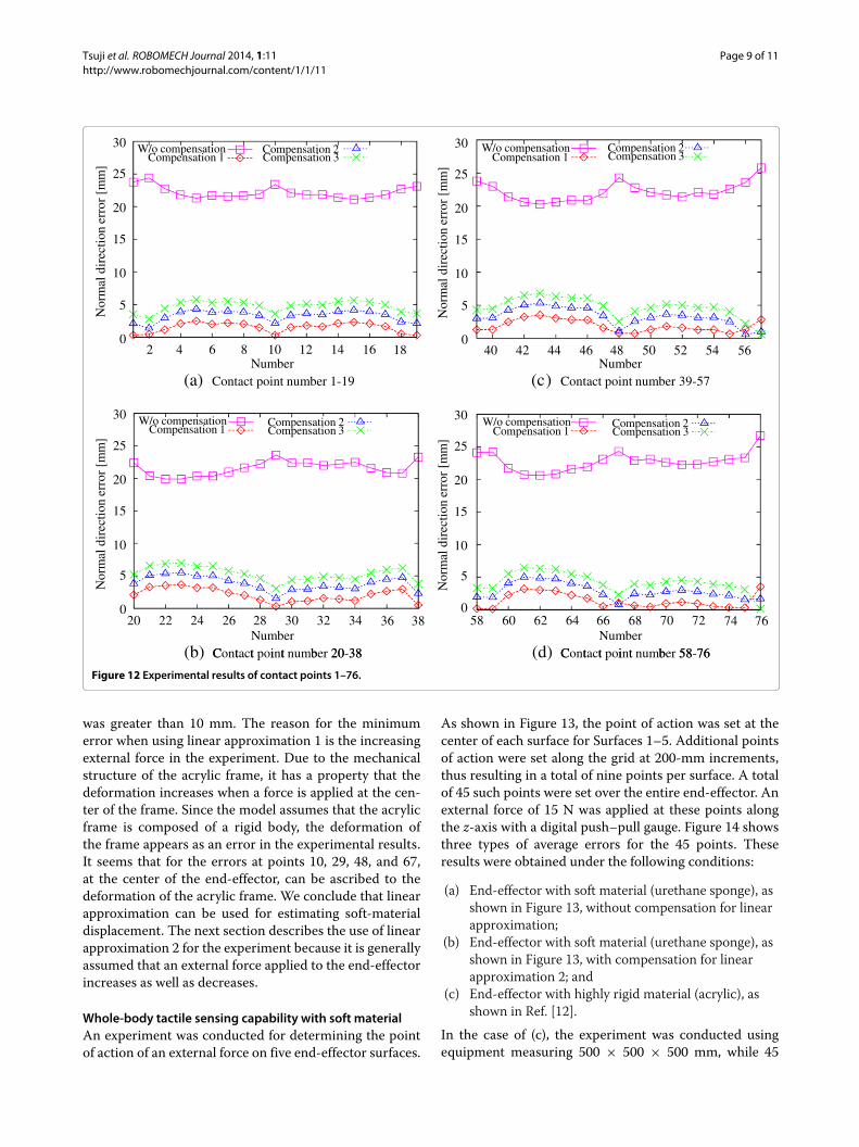
Evaluation of compensationThe three linear approximations yielded experimentalresults for an external force applied at the center of a100 × 100 × 50 mm urethane sponge. Thus, this sectionpresents the linear approximation to a 50-mm-thick ure-thane sponge. There are areas that are not 50 mm thick,such as areas close to the edge of the end-effector. There-fore, the error due to linear approximation was estimatedthrough experimentation for determining the points ofaction of an external force on Surface 1, as shown inFigure 11. The points of action were set at intervals of 30mm and numbered from 1 to 76. The points along thex axis were numbered 1–19, those along the y axis werenumbered 20–38, those along the xy-axis were numbered39–57, and those along the −xy-axis were numbered 58–76. An external force of 15 N was applied in the z-axisdirection to these points with a digital push–pull gauge.Figure 12 shows the error of each linear approxima-
tion along the z axis. The error for the non-compensationcase is the distance from the default position to thedeformed position on the end-effector. This is the softmaterial displacement of the end-effector. The averageerrors obtained for points 1–76 using linear approxima-tions 1, 2, and 3 were 1.7, 3.3, and 4.7 mm, respec-tively. Thus, for the linear approximation experiments, theaverage error was less than 5.0 mm. No individual error
Figure 11 Points of application of external force on Surface 1.
Tsuji et al. ROBOMECH Journal 2014, 1:11 Page 9 of 11http://www.robomechjournal.com/content/1/1/11
2 4 6 8 10 12 14 16 18
20 22 24 26 28 30 32 34 36 38
40 42 44 46 48 50 52 54 56
58 60 62 64 66 68 70 72 74 76
0
5
10
15
20
25
30
0
5
10
15
20
25
30
5
10
15
20
25
30
0
5
10
15
20
25
30
0
W/o compensationCompensation 1
Compensation 2Compensation 3
W/o compensationCompensation 1
Compensation 2Compensation 3
W/o compensationCompensation 1
Compensation 2Compensation 3
W/o compensationCompensation 1
Compensation 2Compensation 3
Nor
mal
dir
ectio
n er
ror
[mm
]
NumberC t t i t b 20 38
Nor
mal
dir
ectio
n er
ror
[mm
]
Nor
mal
dir
ectio
n er
ror
[mm
]
Nor
mal
dir
ectio
n er
ror
[mm
]
NumberC t t i t b 58 76
Number(a) Contact point number 1-19
Number(c) Contact point number 39-57
(b) Contact point number 20-38 (d) Contact point number 58-76
Figure 12 Experimental results of contact points 1–76.
was greater than 10 mm. The reason for the minimumerror when using linear approximation 1 is the increasingexternal force in the experiment. Due to the mechanicalstructure of the acrylic frame, it has a property that thedeformation increases when a force is applied at the cen-ter of the frame. Since the model assumes that the acrylicframe is composed of a rigid body, the deformation ofthe frame appears as an error in the experimental results.It seems that for the errors at points 10, 29, 48, and 67,at the center of the end-effector, can be ascribed to thedeformation of the acrylic frame. We conclude that linearapproximation can be used for estimating soft-materialdisplacement. The next section describes the use of linearapproximation 2 for the experiment because it is generallyassumed that an external force applied to the end-effectorincreases as well as decreases.
Whole-body tactile sensing capability with soft materialAn experiment was conducted for determining the pointof action of an external force on five end-effector surfaces.
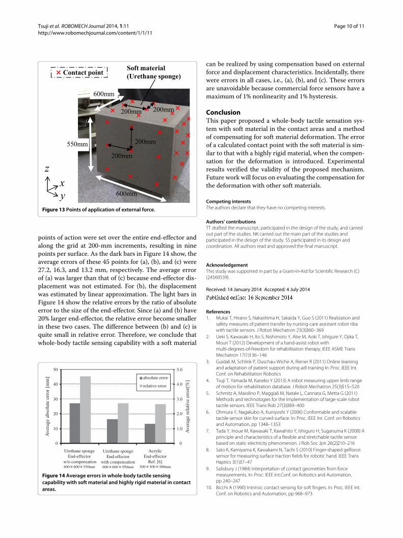
As shown in Figure 13, the point of action was set at thecenter of each surface for Surfaces 1–5. Additional pointsof action were set along the grid at 200-mm increments,thus resulting in a total of nine points per surface. A totalof 45 such points were set over the entire end-effector. Anexternal force of 15 N was applied at these points alongthe z-axis with a digital push–pull gauge. Figure 14 showsthree types of average errors for the 45 points. Theseresults were obtained under the following conditions:
(a) End-effector with soft material (urethane sponge), asshown in Figure 13, without compensation for linearapproximation;
(b) End-effector with soft material (urethane sponge), asshown in Figure 13, with compensation for linearapproximation 2; and
(c) End-effector with highly rigid material (acrylic), asshown in Ref. [12].
In the case of (c), the experiment was conducted usingequipment measuring 500 × 500 × 500 mm, while 45
Tsuji et al. ROBOMECH Journal 2014, 1:11 Page 10 of 11http://www.robomechjournal.com/content/1/1/11
Figure 13 Points of application of external force.
points of action were set over the entire end-effector andalong the grid at 200-mm increments, resulting in ninepoints per surface. As the dark bars in Figure 14 show, theaverage errors of these 45 points for (a), (b), and (c) were27.2, 16.3, and 13.2 mm, respectively. The average errorof (a) was larger than that of (c) because end-effector dis-placement was not estimated. For (b), the displacementwas estimated by linear approximation. The light bars inFigure 14 show the relative errors by the ratio of absoluteerror to the size of the end-effector. Since (a) and (b) have20% larger end-effector, the relative error become smallerin these two cases. The difference between (b) and (c) isquite small in relative error. Therefore, we conclude thatwhole-body tactile sensing capability with a soft material
10
20
30
40
0
50
absolute error
relative error
Urethane spongeEnd-effector
w/o compensation600 600 550mm
Urethane spongeEnd-effector
with compensation600 600 550mm
AcrylicEnd-effector
Ref. [6]500 500 500mm
Ave
rage
abs
olut
e er
ror
[mm
]
Ave
rage
rel
ativ
e er
ror[
%]
1.0
2.0
3.0
4.0
0
5.0
Figure 14 Average errors in whole-body tactile sensingcapability with soft material and highly rigid material in contactareas.
can be realized by using compensation based on externalforce and displacement characteristics. Incidentally, therewere errors in all cases, i.e., (a), (b), and (c). These errorsare unavoidable because commercial force sensors have amaximum of 1% nonlinearity and 1% hysteresis.
ConclusionThis paper proposed a whole-body tactile sensation sys-tem with soft material in the contact areas and a methodof compensating for soft material deformation. The errorof a calculated contact point with the soft material is sim-ilar to that with a highly rigid material, when the compen-sation for the deformation is introduced. Experimentalresults verified the validity of the proposed mechanism.Future work will focus on evaluating the compensation forthe deformation with other soft materials.
Competing interestsThe authors declare that they have no competing interests.
Authors’ contributionsTT drafted the manuscript, participated in the design of the study, and carriedout part of the studies. NK carried out the main part of the studies andparticipated in the design of the study. SS participated in its design andcoordination. All authors read and approved the final manuscript.
AcknowledgementThis study was supported in part by a Grant-in-Aid for Scientific Research (C)(24560539).
Received: 14 January 2014 Accepted: 4 July 2014
References1. Mukai T, Hirano S, Nakashima H, Sakaida Y, Guo S (2011) Realization and
safety measures of patient transfer by nursing-care assistant robot ribawith tactile sensors. J Robot Mechatron 23(3):360–369
2. Ueki S, Kawasaki H, Ito S, Nishimoto Y, Abe M, Aoki T, Ishigure Y, Ojika T,Mouri T (2012) Development of a hand-assist robot withmulti-degrees-of-freedom for rehabilitation therapy. IEEE ASME TransMechatron 17(1):136–146
3. Guidali M, Schlink P, Duschau-Wiche A, Riener R (2011) Online learningand adaptation of patient support during adl training In: Proc. IEEE Int.Conf. on Rehabilitation Robotics
4. Tsuji T, Yamada M, Kaneko Y (2013) A robot measuring upper limb rangeof motion for rehabilitation database. J Robot Mechatron 25(3):515–520
5. Schmitz A, Maiolino P, Maggiali M, Natale L, Cannata G, Metta G (2011)Methods and technologies for the implementation of large-scale robottactile sensors. IEEE Trans Rob 27(3):389–400
6. Ohmura Y, Nagakubo A, Kuniyoshi Y (2006) Conformable and scalabletactile sensor skin for curved surface. In: Proc. IEEE Int. Conf. on Roboticsand Automation, pp 1348–1353
7. Tada Y, Inoue M, Kawasaki T, Kawahito Y, Ishiguro H, Suganuma K (2008) Aprinciple and characteristics of a flexible and stretchable tactile sensorbased on static electricity phenomenon. J Rob Soc Jpn 26(2):210–216
8. Sato K, Kamiyama K, Kawakami N, Tachi S (2010) Finger-shaped gelforce:sensor for measuring surface traction fields for robotic hand. IEEE TransHaptics 3(1):37–47
9. Salisbury J (1984) Interpretation of contact geometries from forcemeasurements. In: Proc. IEEE Int.Conf. on Robotics and Automation,pp 240–247
10. Bicchi A (1990) Intrinsic contact sensing for soft fingers. In: Proc. IEEE Int.Conf. on Robotics and Automation, pp 968–973

Tsuji et al. ROBOMECH Journal 2014, 1:11 Page 11 of 11http://www.robomechjournal.com/content/1/1/11
11. Iwata H, Sugano S (2002) Whole-body covering tactile interface forhuman robot coordination. In: Proc. IEEE Int. Conf. on Robotics andAutomation, pp 3818–3824
12. Tsuji T, Yasuyoshi K, Abe S (2009) Whole-body force sensation by forcesensor with shell-shaped end-effector. IEEE Trans Ind Electron56(5):1375–1382
13. Tsuji T, Ito T (2009) Command recognition by haptic interface on humansupport robot. In: Proc. IEEE/RSJ Int. Conf. on Intelligent Robots andSystems, pp 3178–3183
14. Arakawa J, Tsuji T, Tan D (2010) Personal identification method for robotwith whole-body sensing mechanism. In: Proc. IEEE Int. Conf. on IndustrialElectronics, Control and Instrumentation, pp 1590–1595
15. Cervera E, Gracia-Aracil N, Martinez E, Nomdedeu L, Pobil A (2006) Safetyfor a robot arm moving amidst humans by using panoramic vision.In: Proc. IEEE Int. Conf. on Robotics and Automation, pp 1348–1353
16. Kurita N, Hasunuma H, Sakaino S, Tsuji T (2013) Whole-body tactilesensing by a force sensor using soft material at contact areas. In: Proc.JSME Robotics and Mechatronics Conference. 2A1-A09. (in Japanese)
17. Kurita N, Hasunuma H, Sakaino S, Tsuji T (2013) Simplified whole-bodytactile sensing system using soft material at contact areas. In: Proc. IEEEInt. Conf. on Industrial Electronics, Control and Instrumentation,pp 4264–4269
18. Lankarani HM, Nikravesh PE (1994) Continuous contact force models forimpact analysis in multibody systems. Nonlinear Dynam 5(2):193–207
19. Hayashi M, Sagisaka T, Ishizaka Y, Yoshikai T, Inaba M (2007) Developmentof functional whole-body flesh distributed three-axis force sensors toenable close interaction by humanoids. In: Proc. IEEE/RSJ Int. Conf. onIntelligent Robots and Systems, pp 3610–3615
20. Sugiura Y, Kakehi G, Withana A, Lee C, Sakamoto D, Sugimono M,Igarashi T (2011) Detecting shape deformation of soft objects usingdirectional photoreflectivity measurement. In: Proc. ACM Symp. UserInterface Software and Technology, pp 509–516
doi:10.1186/s40648-014-0011-xCite this article as: Tsuji et al.:Whole-body tactile sensing through a forcesensor using soft materials in contact areas. ROBOMECH Journal 2014 1:11.
Submit your manuscript to a journal and benefi t from:
7 Convenient online submission
7 Rigorous peer review
7 Immediate publication on acceptance
7 Open access: articles freely available online
7 High visibility within the fi eld
7 Retaining the copyright to your article
Submit your next manuscript at 7 springeropen.com