Embed Size (px)
Citation preview

Research and Development of
Residential Heat Pump
Midterm Report: Performance Analysis and Design
Crosby Laboratory
Department of Mechanical Engineering
University of Maine
Orono, Maine
Team Members:
Donald S. Jarvi
Adam Koppel
Kyle Knowlton
Eric Bragdon
Advisor:
Jim LaBrecque

Abstract:
The following will include detailed information relating to the progress of development
on the residential heat pump unit. Information will include performance test data of the
fans, compressors, and heat exchangers as well as public relations progress and goals to
be accomplished the following semester.
Objective:
The heat pump unit was assembled and partially designed by a previous team of
mechanical engineering technology students. The unit was in operating condition and
took little preparation in getting the unit to operate. Our main goal for this semester was
to improve, enhance, and optimize the features of the heat pump making the unit have
higher performance and operate more efficiently. Just by inspection, without the unit
running, we noticed several areas improvement such as fan positioning, aesthetics, and
controls. Currently, the controls system is in crude shape and takes up an unnecessary
volume. The aesthetics of the unit resemble a prototype, which is in fact what the unit is,
and also has loose structure. By the end of this project, we hope to have a unit that will
closely resemble that of one that would be sold by retailers.
Performance:
Upper Heat Exchanger Fan:
After the unit was up and operating, performance data was taken on the compressor, fans,
and heat exchangers. Using the fans performance data provided by the manufacturer, we
immediately saw that the upper coil fan (condenser in the winter evaporator in the
summer) was oversized. But due to the complex positioning of the upper heat exchanger,
various pressure drops would cause this data to be different than the actual capacity of the
fan in our setting. So, an air velocity meter was used to gather a velocity profile of both
upper and lower fans.

Figure 1: A velocity profile as a function of height on upper heat exchanger.
Integrating the velocity profile gives an average velocity of 926.75 ft/min. Using the
exposed heat exchanger area of 1.02 ft2, the air volumetric flow can be computed using
Q=VA, giving an air flow of 810 CFM. From the manufacturer’s fan curve, we should be
achieving about 1200 CFM. This makes the fan less efficient than if a properly sized fan
was used due to unnecessary pressure drops across the awkwardly positioned heat
exchanger.
Lower Heat Exchanger Fan:
For the lower heat exchanger, a radial orientation was used to gather the velocity profile.
Figure 2: A velocity profile as a function of radius for the lower heat exchanger.

Integrating the velocity profile gave an average velocity of 857 ft/min. For the lower heat
exchanger, an area of 1.396 ft2
was used giving a flow rate of 1196.6 CFM. However, this
fan is not oversized where the desired capacity is higher than that of the upper fan.
Compressor:
Compressor performance data was computed after collecting air temperatures off of the
heat exchangers, subcooling temperatures, and subcooling pressures. Temperatures were
collected using a handheld air temperature gage thermocouples attached to subcooling
pipes. Pressure readings were taken using a Texas Instruments pressure transducer.
Heat Energy and Electrical Input vs. Outside Temperature
0.00
0.50
1.00
1.50
2.00
2.50
-40 -20 0 20 40 60 80
Outside Temperature (F)
Heat Energy (tons)
-200
800
1800
2800
3800
4800
5800
6800
7800
8800
Electrical Input (watts)
Heat Energy (tons)
Electrical Energy (watts)
Figure 3: Graphical display of heat energy received and electrical energy put in as a
function of outdoor air temperature.

Figure 4: Plot of coefficient of performance represented in terms of Carnot and
refrigerant performance as a function of outdoor air temperature.
As seen in figures 3 and 4, the compressor delivers a reasonable amount of thermal
energy while reaching COP’s in the range of 3.5 on mild days. NOTE: much of the

thermodynamic analysis of the compressor depends on the isentropic efficiency of the
comressor which we assumed to be n = .9.
Upper Heat Exchanger:
During test analysis, quick temperature readings were taken at various points on both heat
exchangers using an infrared temperature gage. With the compressor running at about
60%, the temperatures on the upper heat exchanger were 110 F where the desired
temperature is about 95 F. The group concluded that this is a poor configuration of fan
size and heat exchanger size combination.
Lower Heat Exchanger:
The lower heat exchanger configuration with its fan seems to be performing to our
desired standards. The group decided to keep this configuration.
Design: After test analysis was completed, areas for improvement were exposed mainly in the
upper heat exchanger. A new fan was sized based on air flow capacity, sound pressure
level, and positioning. The group decided on the EBM Papst R4E310-AR06-01. This fan
is different than the axial fan currently installed on the unit. It features a motorized
impeller design that delivers the same capacity, but with lower sound pressure level and
more capable of overcoming such static pressure over the upper heat exchanger. The new
fan was sized for the following specifications provided to us by the manufacturer.
Figure 5: Fan performance curves provided by the manufacturer. Curve numbers
represent model numbers provided in Figure 6. Source: EBM Papst.
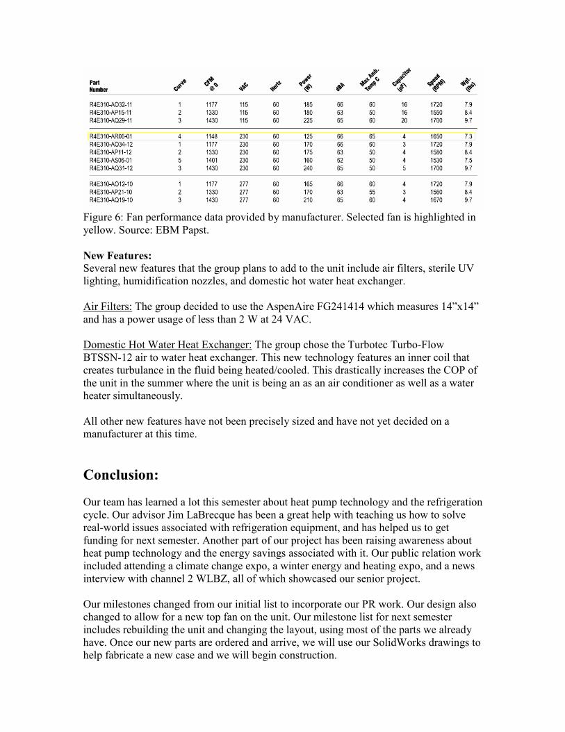
Figure 6: Fan performance data provided by manufacturer. Selected fan is highlighted in
yellow. Source: EBM Papst.
New Features: Several new features that the group plans to add to the unit include air filters, sterile UV
lighting, humidification nozzles, and domestic hot water heat exchanger.
Air Filters: The group decided to use the AspenAire FG241414 which measures 14”x14”
and has a power usage of less than 2 W at 24 VAC.
Domestic Hot Water Heat Exchanger: The group chose the Turbotec Turbo-Flow
BTSSN-12 air to water heat exchanger. This new technology features an inner coil that
creates turbulance in the fluid being heated/cooled. This drastically increases the COP of
the unit in the summer where the unit is being an as an air conditioner as well as a water
heater simultaneously.
All other new features have not been precisely sized and have not yet decided on a
manufacturer at this time.
Conclusion:
Our team has learned a lot this semester about heat pump technology and the refrigeration
cycle. Our advisor Jim LaBrecque has been a great help with teaching us how to solve
real-world issues associated with refrigeration equipment, and has helped us to get
funding for next semester. Another part of our project has been raising awareness about
heat pump technology and the energy savings associated with it. Our public relation work
included attending a climate change expo, a winter energy and heating expo, and a news
interview with channel 2 WLBZ, all of which showcased our senior project.
Our milestones changed from our initial list to incorporate our PR work. Our design also
changed to allow for a new top fan on the unit. Our milestone list for next semester
includes rebuilding the unit and changing the layout, using most of the parts we already
have. Once our new parts are ordered and arrive, we will use our SolidWorks drawings to
help fabricate a new case and we will begin construction.

Parts List:
Compressor Panasonic Rotary model 5KD240XAC21
Spec. No. SC- 52173009 -A
Capacity: 2 Ton
Electronic Expansion Valve Parker Electronically Controlled type with 650 steps of resolution
Inlet: 1/4" Outlet: 3/8"
Coils AlumiCool Micro-channel
Top coil dimensions: 15.55" x 10.2"
Bottom coil dimensions: 15.55" x 30.2"
Filter Dryer Parker
Size: 4.5" long x 3" diameter
Top Fan
EBM Papst EC centrifugal fan model R3G 310-AP52-01, motor M3G074-CF
Inlet ring: model 31051-2-4013
Size: 310mm diameter
Blade style: backward-curved
Bottom Fan
EBM Papst EC Axial fan model A3G300- AB56 -02
Size: 300mm
Blade style: sickled
Ventilation Fan
EBM Papst VarioPro model 6248N12P
Desuperheater Coil For DHW Production
TurboTec model BTSSN-12
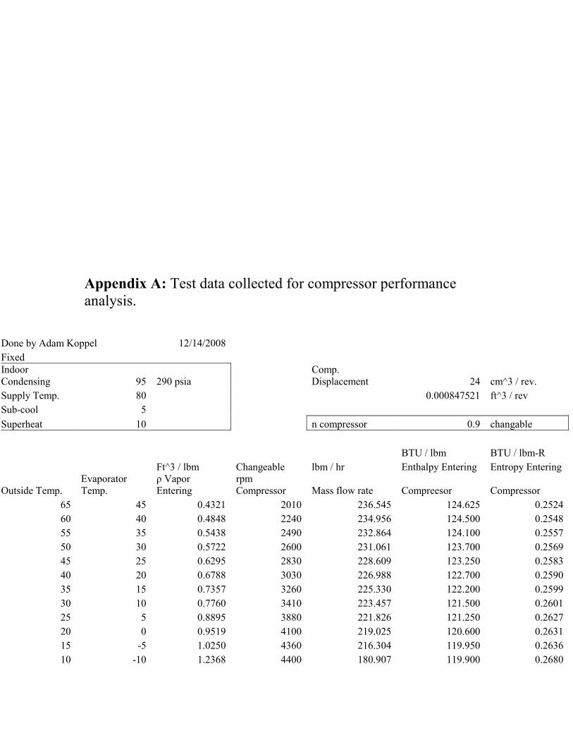
Appendix A: Test data collected for compressor performance
analysis.
Done by Adam Koppel 12/14/2008
Fixed
Indoor
Condensing 95 290 psia
Comp.
Displacement 24 cm^3 / rev.
Supply Temp. 80 0.000847521 ft^3 / rev
Sub-cool 5
Superheat 10 n compressor 0.9 changable
BTU / lbm BTU / lbm-R
Ft^3 / lbm Changeable lbm / hr Enthalpy Entering Entropy Entering
Outside Temp.
Evaporator
Temp.
ρ Vapor
Entering
rpm
Compressor Mass flow rate Compreesor Compressor
65 45 0.4321 2010 236.545 124.625 0.2524
60 40 0.4848 2240 234.956 124.500 0.2548
55 35 0.5438 2490 232.864 124.100 0.2557
50 30 0.5722 2600 231.061 123.700 0.2569
45 25 0.6295 2830 228.609 123.250 0.2583
40 20 0.6788 3030 226.988 122.700 0.2590
35 15 0.7357 3260 225.330 122.200 0.2599
30 10 0.7760 3410 223.457 121.500 0.2601
25 5 0.8895 3880 221.826 121.250 0.2627
20 0 0.9519 4100 219.025 120.600 0.2631
15 -5 1.0250 4360 216.304 119.950 0.2636
10 -10 1.2368 4400 180.907 119.900 0.2680

5 -15 1.3349 4400 167.612 119.200 0.2686
0 -20 1.4915 4400 150.014 118.700 0.2703
-5 -25 1.6425 4400 136.223 118.050 0.2716
-10 -30 1.8932 4400 118.184 117.600 0.2742
-15 -35 2.0730 4400 107.933 116.900 0.2752
-20 -40 2.3937 4400 93.473 116.400 0.2779
-30 -50 2.9445 4400 75.988 115.100 0.2806
fixed
Assuming Coil can handle load
Isentropic Isentropic Enthalpy taking
Temp. Exiting
Enthalpy
Exiting isentropic n into Actual Comp. Enthalpy Exiting
Compressor Compressor Account Exiting Temp. Condenser
120.0 132.70 147.44 173.0 46.00
122.5 133.48 148.31 176.3 46.00
125.0 134.25 149.17 179.5 46.00
127.5 135.03 150.03 182.7 46.00
130.0 135.80 150.89 185.9 46.00
132.5 136.55 151.72 189.0 46.00
135.0 137.30 152.56 192.1 46.00
137.5 138.05 153.39 195.2 46.00
140.0 138.80 154.22 198.3 46.00
144.0 139.94 155.49 203.1 46.00
148.0 141.08 156.76 207.8 46.00
152.0 142.22 158.02 212.5 46.00
156.0 143.36 159.29 217.2 46.00
160.0 144.50 160.56 222.0 46.00
165.0 145.90 162.11 227.8 46.00
170.0 147.30 163.67 233.6 46.00
175.0 148.65 165.17 239.2 46.00

180.0 150.00 166.67 244.8 46.00
185.0 151.35 168.17 250.3 46.00
BTU/ hr Tons BTU / lbm BTU/ hr BTU / lbm BTU/ hr Watts
Q dot high
Tons of
Heating Q low Q dot low W Compressor
W dot
Compresser
W dot
Compresser
23996 2.00 -78.625 -18598 22.82 5398 1583
24037 2.00 -78.500 -18444 23.81 5593 1640
24024 2.00 -78.100 -18187 25.07 5837 1712
24038 2.00 -77.700 -17953 26.33 6085 1784
23978 2.00 -77.250 -17660 27.64 6318 1853
23998 2.00 -76.700 -17410 29.02 6588 1932
24010 2.00 -76.200 -17170 30.36 6840 2006
23997 2.00 -75.500 -16871 31.89 7126 2090
24006 2.00 -75.250 -16692 32.97 7314 2145
23981 2.00 -74.600 -16339 34.89 7642 2241
23957 2.00 -73.950 -15996 36.81 7961 2335
20266 1.69 -73.900 -13369 38.12 6897 2022
18989 1.58 -73.200 -12269 40.09 6719 1970
17185 1.43 -72.700 -10906 41.86 6279 1841
15817 1.32 -72.050 -9815 44.06 6002 1760
13906 1.16 -71.600 -8462 46.07 5444 1597
12862 1.07 -70.900 -7652 48.27 5210 1528
11279 0.94 -70.400 -6580 50.27 4699 1378
9283 0.77 -69.100 -5251 53.07 4032 1183
COP Carnot COP Refirgerant
11.10 4.45
10.09 4.30
9.25 4.12
8.54 3.95
7.93 3.79

7.40 3.64
6.94 3.51
6.53 3.37
6.17 3.28
5.84 3.14
5.55 3.01
5.29 2.94
5.05 2.83
4.83 2.74
4.63 2.64
4.44 2.55
4.27 2.47
4.11 2.40
3.83 2.30