Embed Size (px)
Citation preview

Review of Australian standard AS 5100 Bridge design with a view to adoption – Volume 2 October 2008 Research Report 361


Review of Australian standard AS 5100 Bridge design with a view to adoption
Volume 2
D. K. Kirkcaldie Opus International Consultants Limited Wellington
J. H. Wood John Wood Consulting Lower Hutt
NZ Transport Agency Research Report 361
ISBN 978-0-478-33424-1 ISSN 1173-3756
© 2008, NZ Transport Agency
Private Bag 6995, Wellington 6141, New Zealand
Telephone 64 4 894 5400; Facsimile 64 4 894 6100
Email: [email protected]
Website: www.nzta.govt.nz
Kirkcaldie, D. K., and Wood, J. H. 2008. Review of Australian standard AS 5100
Bridge design with a view to adoption. Volume 2. NZ Transport Agency Research
Report 361. 184 pp.
This report is published in two volumes as follows:
Volume 1: Executive summary, recommendations and parts 1 to 4
Volume 2: Parts 5 to 8
Keywords: AS 5100, Australian bridge design, Transit NZ Bridge manual
An important note for the reader
The NZ Transport Agency is a Crown entity established under the Land Transport
Management Amendment Act 2008. The objective of the NZ Transport Agency is to
undertake its functions in a way that contributes to an affordable, integrated, safe,
responsive, and sustainable land transport system. Each year, the NZ Transport Agency
invests a portion of its funds on research that contributes to this objective.
This report is the final stage of a project commissioned by Land Transport New Zealand
before 31 July 2008 and is published by the NZ Transport Agency.
While this report is believed to be correct at the time of its preparation, the NZ Transport
Agency, and its employees and agents involved in its preparation and publication, cannot
accept any liability for its contents or for any consequences arising from its use. People
using the contents of the document, whether directly or indirectly, should apply and rely
on their own skill and judgement. They should not rely on its contents in isolation from
other sources of advice and information. If necessary, they should seek appropriate legal
or other expert advice in relation to their own circumstances, and to the use of this report.
The material contained in this report is the output of research and should not be
construed in any way as policy adopted by the NZ Transport Agency but may be used in
the formulation of future policy.
Additional note
The NZ Transport Agency (NZTA) was formally established on 1 August 2008, combining
the functions and expertise of Land Transport NZ and Transit NZ.
The new organisation will provide an integrated approach to transport planning, funding
and delivery.
This research report was prepared prior to the establishment of the NZTA and may refer to
Land Transport NZ and Transit NZ.

Acknowledgments
The authors would like to acknowledge the contributions made to this project by the peer
reviewers: Howard Chapman and Ian Billings, and the project steering group: Frank
McGuire (formerly Transit New Zealand), Ron Muir (Hutt City Council), Charles Clifton
(University of Auckland), and Ross Cato (Precast NZ).
Abbreviations and acronyms
AADT Annual average daily traffic
ACI American Concrete Institute
AS Australian standard
AS 5100 AS 5100:2004. Bridge design.
ASTM American Society for Testing and Materials
Bridge manual Bridge manual, 2nd edition 2003 and amendments, Transit New
Zealand
BS British standard
BSI British Standards Institute
GP General purpose
HLP Heavy load platform
NZBC New Zealand Building Code
NZS New Zealand standard
NZTA New Zealand Transport Agency
SAI SAI Global Ltd
SLS Serviceability limit state
SP Structural purpose
TOPS Transit New Zealand’s Overweight Permit System
Transit Transit New Zealand (now NZ Transport Agency)
Transit NZ Transit New Zealand (now NZ Transport Agency)
UDL Uniformly distributed load
ULS Ultimate limit state

Contents: Volume 2
5 AS 5100.5: Concrete ............................................................................................................ 7
AS 5100.5 content ..................................................................................................................................7
5.1 Scope and general........................................................................................................................8 5.2 Design requirements and procedures.........................................................................................12 5.3 Loads and load combinations for stability, strength and serviceability .......................................25 5.4 Design for durability ..................................................................................................................26 5.5 Design for fire resistance ...........................................................................................................29 5.6 Design properties of materials ...................................................................................................30 5.7 Methods of structural analysis ...................................................................................................35 5.8 Design of beams for strength and serviceability.........................................................................39 5.9 Design of slabs for strength and serviceability ...........................................................................51 5.10 Design of column and tension members for strength and serviceability .....................................56 5.11 Design of walls ..........................................................................................................................65 5.12 Design of non-flexural members, end zones and bearing surfaces.............................................68 5.13 Stress development and splicing of reinforcement and tendons .................................................75 5.14 Joints, embedded items, fixing and connections ........................................................................80 5.15 Plain concrete members.............................................................................................................84 5.16 Material and construction requirements.....................................................................................84 5.17 Testing of members and structures............................................................................................85 5.18 Appendix A: Referenced documents...........................................................................................89 5.19 Appendix B: Design of segmental concrete bridges (normative) .................................................92 5.20 Appendix C: Beam stability during erection (normative) .............................................................93 5.21 Appendix D: Suspension reinforcement design procedures (normative) .....................................93 5.22 Appendix E: Composite concrete members design procedures (normative) ................................94 5.23 Appendix F: Box girders (normative) ..........................................................................................94 5.24 Appendix G: End zones for prestressing anchorages (informative) .............................................95 5.25 Appendix H: Standard precast prestressed concrete girders (informative) ..................................95 5.26 Appendix I: References (informative) .......................................................................................96 5.27 NZS 3101 material not included within AS 5100.5......................................................................96 5.28 Bridge manual provisions for concrete bridge design.................................................................98 5.29 Limitations of NZS 3101 for bridge design ...............................................................................100
6 AS 5100.6: Steel and composite construction ................................................................ 103 AS 5100.6 content ..............................................................................................................................103 6.1 Scope and general....................................................................................................................104 6.2 Materials..................................................................................................................................105 6.3 General design requirements ...................................................................................................107 6.4 Methods of structural analysis .................................................................................................108 6.5 Steel beams .............................................................................................................................112 6.6 Composite beams ....................................................................................................................118 6.7 Composite box girders ............................................................................................................129 6.8 Transverse members and restraints .........................................................................................130 6.9 Members subject to axial tension.............................................................................................131 6.10 Members subject to axial compression ....................................................................................131 6.11 Members subject to combined actions .....................................................................................133 6.12 Connections.............................................................................................................................135 6.13 Fatigue.....................................................................................................................................140 6.14 Brittle fracture..........................................................................................................................144 6.15 Testing of structures or elements ............................................................................................146 6.16 Elastic resistance to lateral buckling (appendix A) ....................................................................147
5

6
6.17 Strength of stiffened web panels (appendix B) ......................................................................... 148 6.18 Second order elastic analysis (appendix C) .............................................................................. 148 6.19 Eccentrically loaded double-bolted or welded single angles in trusses (appendix D) ................ 149 6.20 Nominal moment capacity for composite sections under sagging moment (appendix E) .......... 150 6.21 Interaction curves for composite columns (appendix F) ........................................................... 150 6.22 Fabrication (appendix G).......................................................................................................... 150 6.23 Erection (appendix H) .............................................................................................................. 152 6.24 Modification of existing structures (appendix I) ....................................................................... 152 6.25 NZS 3404 material not included within AS 5100.6 ................................................................... 153
7 AS 5100.7: Rating of existing bridges ............................................................................ 156 AS 5100.7 Content ............................................................................................................................. 156 7.1 Scope and general ................................................................................................................... 156 7.2 Referenced documents ............................................................................................................ 157 7.3 Notation .................................................................................................................................. 157 7.4 Rating philosophy.................................................................................................................... 158 7.5 Assessment of load capacity.................................................................................................... 159 7.6 Load testing ............................................................................................................................ 159 7.7 Assessment of the actual loads................................................................................................ 160 7.8 Fatigue .................................................................................................................................... 161 7.9 Appendix A: Road and rail traffic design loads from previous Australian bridge design code,
Austroads codes, ANZRC and AREA ......................................................................................... 161 7.10 Summary of AS 5100.7 ............................................................................................................ 161
8 Topics not included in AS 5100, requiring coverage ..................................................... 163 8.1 Overview ................................................................................................................................. 163 8.2 Bridge design statement .......................................................................................................... 163 8.3 Influence of approaches .......................................................................................................... 164 8.4 Aesthetics................................................................................................................................ 164 8.5 Special studies......................................................................................................................... 164 8.6 Design of earthworks............................................................................................................... 164 8.7 Seismic design of steel structures............................................................................................ 166 8.8 Seismic design of concrete structures...................................................................................... 166 8.9 Empirical design of reinforced concrete deck slabs.................................................................. 166 8.10 Earthquake resistant design..................................................................................................... 167 8.11 Structural strengthening.......................................................................................................... 173 8.12 Bridge side protection ............................................................................................................. 175 8.13 Toroidal rubber buffers ........................................................................................................... 179 8.14 Lightly trafficked rural bridges................................................................................................. 179 8.15 Bridge site information summary............................................................................................. 180 8.16 Summary on topics not included in AS 5100............................................................................ 181
References ............................................................................................................................. 182
5 AS 5100.5: Concrete
5 AS 5100.5: Concrete
AS 5100.5 content
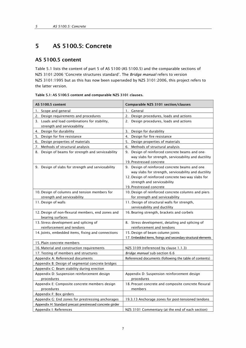
Table 5.1 lists the content of part 5 of AS 5100 (AS 5100.5) and the comparable sections of
NZS 3101:2006 ‘Concrete structures standard’. The Bridge manual refers to version
NZS 3101:1995 but as this has now been superseded by NZS 3101:2006, this project refers to
the latter version.
Table 5.1: AS 5100.5 content and comparable NZS 3101 clauses.
AS 5100.5 content Comparable NZS 3101 section/clauses
1. Scope and general 1. General
2. Design requirements and procedures 2. Design procedures, loads and actions
3. Loads and load combinations for stability,
strength and serviceability
2. Design procedures, loads and actions
4. Design for durability 3. Design for durability
5. Design for fire resistance 4. Design for fire resistance
6. Design properties of materials 5. Design properties of materials
7. Methods of structural analysis 6. Methods of structural analysis
8. Design of beams for strength and serviceability 9. Design of reinforced concrete beams and one-
way slabs for strength, serviceability and ductility
19. Prestressed concrete
9. Design of slabs for strength and serviceability 9. Design of reinforced concrete beams and one
way slabs for strength, serviceability and ductility
12. Design of reinforced concrete two-way slabs for
strength and serviceability
19. Prestressed concrete
10. Design of columns and tension members for
strength and serviceability
10. Design of reinforced concrete columns and piers
for strength and serviceability
11. Design of walls 11. Design of structural walls for strength,
serviceability and ductility
12. Design of non-flexural members, end zones and
bearing surfaces
16. Bearing strength, brackets and corbels
13. Stress development and splicing of
reinforcement and tendons
8. Stress development, detailing and splicing of
reinforcement and tendons
14. Joints, embedded items, fixing and connections 15. Design of beam column joints
17. Embedded items, fixings and secondary structural elements
15. Plain concrete members
16. Material and construction requirements NZS 3109 (referenced by clause 1.1.3)
17. Testing of members and structures Bridge manual sub-section 6.6
Appendix A: Referenced documents Referenced documents (following the table of contents)
Appendix B: Design of segmental concrete bridges
Appendix C: Beam stability during erection
Appendix D: Suspension reinforcement design
procedures
Appendix D: Suspension reinforcement design
procedures
Appendix E: Composite concrete members design
procedures
18. Precast concrete and composite concrete flexural
members
Appendix F: Box girders
Appendix G: End zones for prestressing anchorages 19.3.13 Anchorage zones for post-tensioned tendons
Appendix H: Standard precast prestressed concrete girder
Appendix I: References NZS 3101 Commentary (at the end of each section)
7

REVIEW OF AUSTRALIAN STANDARD AS 5100 ‘BRIDGE DESIGN’ WITH A VIEW TO ADOPTION. VOLUME 2
5.1 Scope and general
5.1.1 Outline of coverage
Section 1 of AS 5100.5 covers:
scope and application
referenced documents
definitions
notation
use of alternative materials or methods
design
materials and construction requirement.
5.1.2 Variation of requirements from NZS 3101
5.1.2.1 Scope and application
AS 5100.5 includes minimum requirements for plain concrete, whereas NZS 3101 deals only with
reinforced and prestressed concrete structures.
AS 5100.5 applies to structures made with the following materials:
concrete with a 28-day compressive strength in the range of 25 MPa to 65 MPa and
saturated surface-dry density in the range of 2100 kg/m3 to 2800 kg/m3
reinforcing steels complying with AS/NZS 4671 and the following criteria:
- yield strength 500 MPa and ductility class N may be used without restriction in all
applications covered by the standard
- yield strength 500 MPa and ductility class L may not be used where the reinforcement is
expected to undergo large deformations or is likely to be bent or rebent on site
- round bar of yield strength 250 MPa and ductility class N may only be used for fitments
prestressing tendons complying with AS 1310, AS 1311 or AS 1313 as appropriate.
NZS 3101 does not define the structures it applies to as clearly in terms of the materials used,
but in section 5, its provisions can be taken to apply to structures using the following materials:
concrete with a 28-day compressive strength, in the range of 25 MPa to 100 MPa but not
exceeding 70 MPa, in elements required to perform in a ductile or limited ductile manner.
Properties given in section 5 relate to concrete with a saturated surface dry density in the
range of 1800 kg/m3 to 2800 kg/m3
reinforcing steels complying with AS/NZS 4671, subject to the following qualifications:
- Grade 500 MPa steel manufactured by the in-line quenched and tempered process is not
to be used where welding, galvanising, hot bending or threading of bars occurs
- Class E steel is to be used unless the conditions for use of class N are satisfied. Class L
steel is not to be used.
- Class N steel may only be used where either:
(i) a member is not subject to seismic action and the strain sustained at the ultimate
limit state (ULS) does not exceed 0.033
8
5 AS 5100.5: Concrete
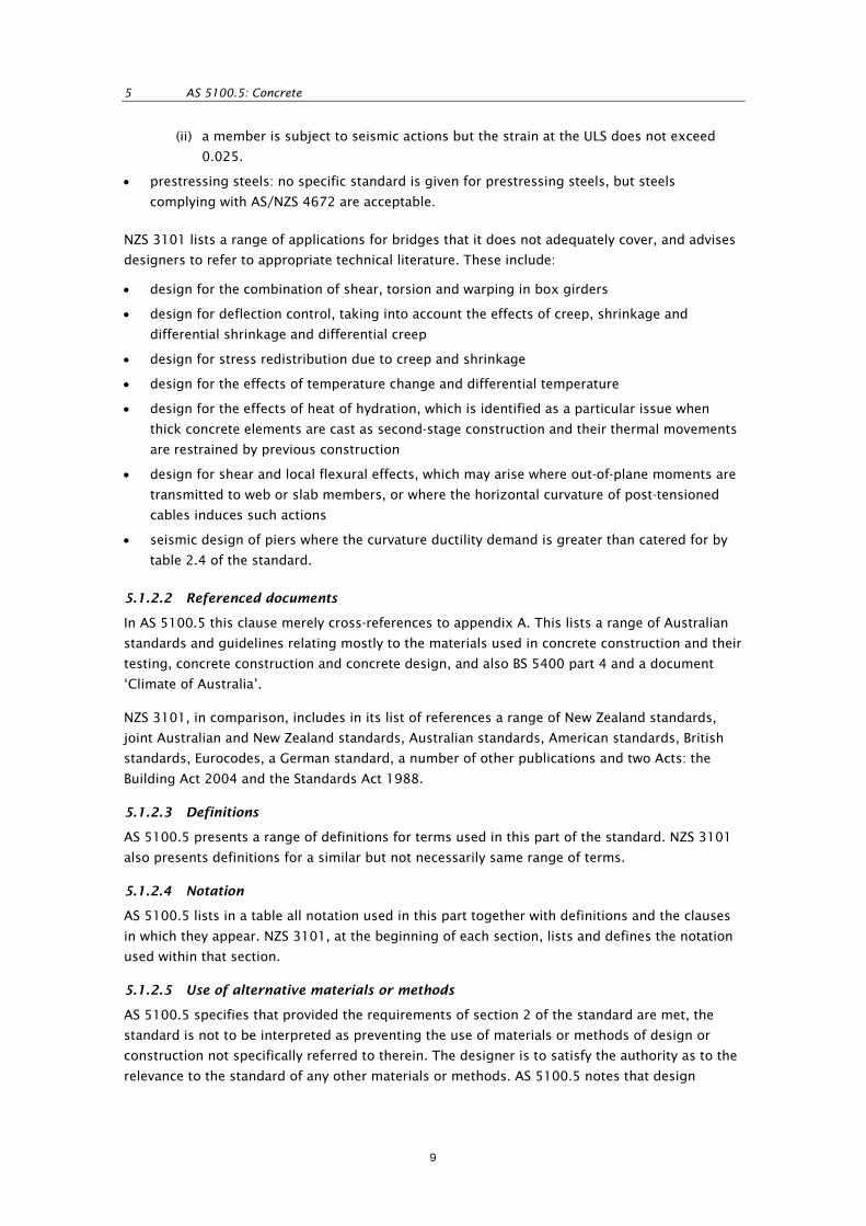
(ii) a member is subject to seismic actions but the strain at the ULS does not exceed
0.025.
prestressing steels: no specific standard is given for prestressing steels, but steels
complying with AS/NZS 4672 are acceptable.
NZS 3101 lists a range of applications for bridges that it does not adequately cover, and advises
designers to refer to appropriate technical literature. These include:
design for the combination of shear, torsion and warping in box girders
design for deflection control, taking into account the effects of creep, shrinkage and
differential shrinkage and differential creep
design for stress redistribution due to creep and shrinkage
design for the effects of temperature change and differential temperature
design for the effects of heat of hydration, which is identified as a particular issue when
thick concrete elements are cast as second-stage construction and their thermal movements
are restrained by previous construction
design for shear and local flexural effects, which may arise where out-of-plane moments are
transmitted to web or slab members, or where the horizontal curvature of post-tensioned
cables induces such actions
seismic design of piers where the curvature ductility demand is greater than catered for by
table 2.4 of the standard.
5.1.2.2 Referenced documents
In AS 5100.5 this clause merely cross-references to appendix A. This lists a range of Australian
standards and guidelines relating mostly to the materials used in concrete construction and their
testing, concrete construction and concrete design, and also BS 5400 part 4 and a document
‘Climate of Australia’.
NZS 3101, in comparison, includes in its list of references a range of New Zealand standards,
joint Australian and New Zealand standards, Australian standards, American standards, British
standards, Eurocodes, a German standard, a number of other publications and two Acts: the
Building Act 2004 and the Standards Act 1988.
5.1.2.3 Definitions
AS 5100.5 presents a range of definitions for terms used in this part of the standard. NZS 3101
also presents definitions for a similar but not necessarily same range of terms.
5.1.2.4 Notation
AS 5100.5 lists in a table all notation used in this part together with definitions and the clauses
in which they appear. NZS 3101, at the beginning of each section, lists and defines the notation
used within that section.
5.1.2.5 Use of alternative materials or methods
AS 5100.5 specifies that provided the requirements of section 2 of the standard are met, the
standard is not to be interpreted as preventing the use of materials or methods of design or
construction not specifically referred to therein. The designer is to satisfy the authority as to the
relevance to the standard of any other materials or methods. AS 5100.5 notes that design
9

REVIEW OF AUSTRALIAN STANDARD AS 5100 ‘BRIDGE DESIGN’ WITH A VIEW TO ADOPTION. VOLUME 2
requirements for lightweight structural concrete are not fully covered by the standard. There is
no similar restriction stated in NZS 3101.
5.1.2.6 Design
AS 5100.5 requires the following design data to be shown on the drawings, in addition to data
specified in AS 5100.2:
exposure classification for durability
class, and where appropriate, grade designation of concrete
grade and type of reinforcement and tendons.
The drawings or specification for concrete members and structures are also to include, as
appropriate, the following:
the shape and size of each member
the finish and method of control for unformed surfaces
class of formwork for the surface finish specified
the size, quantity and location of all reinforcement, tendons and structural fixings and the
cover to each
any required properties of the concrete
the curing procedure
the force required in each tendon, the maximum jacking force to be applied, and the order
in which tendons are to be stressed
the minimum strength the concrete is to attain before the application of prestressing forces
the locations and details of planned construction or movement joints, connections and
splices, and the method to be used for their protection
the minimum period before stripping of forms and removal of shores
any constraint on construction assumed in the design including, where relevant, the casting
procedure
any other requirements.
NZS 3101, by comparison, presents a similar but somewhat different list, requiring consent
documentation and the drawings or specification, or both, for concrete members and structures
to include, where relevant, the following:
the reference number and date of issue of applicable design standards used
the fire resistance ratings if applicable
the concrete strengths
the reinforcing and prestressing steel class and grades used and the manufacturing method
employed in the production of the reinforcing steel
the testing methods, reporting requirements and acceptance criteria for any tests of material
properties, components or assemblages that are required by the standard
the locations and details of planned construction joints
any constraints on construction assumed in the design
the camber of any members.
10

5 AS 5100.5: Concrete
5.1.2.7 Materials and construction requirement
AS 5100.5 states that the requirements of the standard are such that the standards of materials
and construction are not to be less than, and the tolerances not greater than, those set out in
section 16 of the standard.
NZS 3101, on the other hand, applies to structures and parts of structures constructed in
accordance with the materials and workmanship requirements of NZS 3109.
5.1.2.8 Additional requirements presented in NZS 3101 not covered by AS 5100.5
Relationship to the New Zealand Building Code
NZS 3101 states, in relation to the New Zealand Building Code (NZBC), that it sets out minimum
requirements for the design of reinforced and prestressed concrete structures. However, where
the standard has provisions that are in non-specific or unquantified terms these do not form part
of the verification method for the NZBC and the proposed details must be submitted to a
building consent authority for approval as part of the building consent application. This
includes, but is not limited to, where the standard calls for special studies, for a rational
analysis, for engineering judgement to be applied or where the standard requires tests to be
‘suitable’ or ‘appropriate’.
Construction review
NZS 3101 requires all stages of construction of a structure or part of a structure to which the
standard applies to be adequately reviewed by a person who, on the basis of experience or
qualifications, is competent to undertake the review.
Also, the extent of review to be undertaken is to be nominated by the design engineer, taking
into account materials and workmanship factors that are likely to influence the ability of the
finished construction to perform in the predicted manner.
5.1.3 Suitability and actions required to enable adoption
This section requires significant amendment in order to be suitable for adoption in New Zealand.
The amendments required include:
alignment of the reinforcing steels acceptable for use with those specified in NZS 3101
extension of the list of references to include New Zealand and international documents
relevant to New Zealand practice, including relevant New Zealand legislation
an amalgamation of the AS 5100.5 and NZS 3101 list of information for inclusion on the
drawings or in the specification
a statement on the relationship of the standard to the NZBC
requirements relating to construction review.
Reference to relevant New Zealand legislation, a statement on the relationship of the standard to
the NZBC, and requirements relating to construction review should perhaps more appropriately
be incorporated into AS 5100.1.
11
REVIEW OF AUSTRALIAN STANDARD AS 5100 ‘BRIDGE DESIGN’ WITH A VIEW TO ADOPTION. VOLUME 2
5.2 Design requirements and procedures
5.2.1 Outline of coverage
Section 2 of AS 5100.5 covers general requirements for the following with, in many cases,
reference to more specific requirements elsewhere:
design requirements
strength
durability
fire resistance
fatigue
design for stability
deflections of beams and slabs
cracking
vibration
design for strength and serviceability by prototype testing
other design requirements.
5.2.2 Variation of requirements from NZS 3101
5.2.2.1 Design requirements
AS 5100.5 and NZS 3101 set out similar general design requirements.
5.2.2.2 Strength
AS 5100.5 includes design requirements for segmental bridges in its appendix B, whereas there
are no equivalent requirements in NZS 3101.
NZS 3101 specifically requires the consideration and provision of effects of construction
sequence, formwork stripping and back propping, differential settlement of foundations and
lateral ground movements.
NZS 3101 generally adopts slightly higher ULS strength reduction factors than AS 5100.5 and
also specifies capacity design overstrength factors, which are not covered by AS 5100.5.
NZS 3101 does not list strength reduction factors for axial loads not acting with flexure. It
assumes that the same strength reduction factor applies as for axial load acting together with
flexure. NZS 3101 also does not specify strength reduction factors for unreinforced concrete
(not covered by the standard) or separately specify strength reduction factors for embedded
fixings, while AS 5100.5 does not separately specify strength reduction factors (‘capacity
reduction’ in AS 5100.5 terminology) for strut and tie models, corbels or design under fire
exposure.
5.2.2.3 Durability
Both standards present similar cross references to other sections for durability requirements.
5.2.2.4 Fire resistance
AS 5100.5 requires that where it is necessary for a bridge or part thereof to be designed for fire
resistance, the requirements of AS 5100.5 section 5 are to apply.
12
5 AS 5100.5: Concrete
NZS 3101 requires design for fire resistance to comply with its section 4, but makes no
reference to the need or otherwise to consider fire resistance in the design of bridges.
5.2.2.5 Fatigue
AS 5100.5 sets out detailed requirements for fatigue, considering compression in the concrete,
shear, and tensile stresses in reinforcing and prestressing steels, based on the fatigue design
load specified in AS 5100.2.
NZS 3101 merely limits the stress range in straight reinforcement to less than 150 MPa and in
straight prestressing strand to less than 200 MPa (section 19) and refers to the Bridge manual
for the design vehicle loading as a basis for assessing the fatigue stress range.
5.2.2.6 Design for stability
AS 5100.5 requires the structure as a whole and its parts to be designed to maintain stability
against sliding, overturning and uplift. In AS 5100.1, stability is considered to be a ULS.
NZS 3101 more specifically requires the stability of the structure as a whole and of its
components to be ensured under the ULS load combinations.
5.2.2.7 Deflection of beams and slabs
AS 5100.5 requires the deflection of beams, box girders and slabs under service conditions to
be within deflection limits specified in AS 5100.2.
NZS 3101 requires the deflection in concrete structures or members to either be determined in
accordance with methods specified in its section 6.8 and to meet limits specified by AS/
NZS 1170 or other referenced loading standards, or for the element being considered to meet
the minimum thicknesses specified in the standard. For the calculation of deflection, section 6.8
requires the effects of cracking, tension stiffening, shrinkage, creep and relaxation to be taken
into account. In addition, for bridges, the design of bridge girders is to mitigate the deflection
due to the combination of permanent loads, shrinkage, prestress and creep over the long term
to ensure appropriate ride quality and drainage of the bridge deck.
5.2.2.8 Cracking
Reinforced concrete
Section 2 of AS 5100.5 refers to subsequent clauses 8.6 and 9.4 for requirements for control of
cracking in beams and slabs. Where crack control is considered necessary for reasons of
durability, section 2 specifies the following minimum requirements:
for members less than 150 mm thick, a single layer of reinforcement providing not less than
500 mm2/m in each of two orthogonal directions
for members greater than 150 mm thick, a layer of reinforcement in each face providing not
less than 500 mm2/m in each of two orthogonal directions
the spacing of the reinforcement in each of the orthogonal directions is not to exceed
300 mm.
There is close similarity between the requirements for beams set out in clause 8.6 and those for
slabs set out in clause 9.4. For ease of comparison with the NZS 3101 these requirements will be
presented here rather than later when sections 8 and 9 of AS 5100.5 are discussed.
13
REVIEW OF AUSTRALIAN STANDARD AS 5100 ‘BRIDGE DESIGN’ WITH A VIEW TO ADOPTION. VOLUME 2
AS 5100.5 considers cracking in beams subject to tension or flexure to be effectively controlled
if items a), b), c) and either d) for beam subject to tension or e) for beams subject to flexure,
below, are satisfied. A beam is considered to be primarily in tension when the whole section is in
tension, or to be primarily in flexure when the tensile stress distribution in the section is
triangular and part of the section is in compression.
For slabs, a critical tensile zone is defined as a region where the SLS design moment is greater
than or equal to the critical moment for flexural cracking, calculated assuming a concrete tensile
strength of 3.0 MPa. Cracking is similarly deemed to be controlled if a), b), c) and f) and either d)
for slabs subject to tension or e) for slabs subject to flexure, below, are satisfied:
a) The minimum area of reinforcement in the tensile zone is required to be:
Ast,min = 3ksAct/fs
Where: ks = 0.8 for sections primarily in tension, or 0.6 for sections primarily in flexure
Act = area of concrete in the tensile zone, being that part in tension assuming the
section to be uncracked
fs = maximum tensile stress permitted in the reinforcement immediately after
formation of a crack, which shall be the lesser of the yield strength of the
reinforcement and the maximum stress given in table 5.2 for beams, or table
5.3 for slabs, for the largest nominal diameter of the bars in the section
b) The distance from the side or soffit of a beam to the centre of the nearest longitudinal bar is
not to be greater than 100 mm. The spacing of bars near a tension face of the beam is not
to be greater than 300 mm. For T-beams and L-beams, the reinforcement required in the
flange is to be distributed across the effective width. For slabs, the spacing of the bars in
each direction is not to be greater than the lesser of twice the overall depth of the slab or
300 mm. For both beams and slabs, bars with a diameter less than half the diameter of the
largest bar in the cross-section are to be ignored.
c) Load effects are to be considered for the following two load cases:
(i) serviceability limit load combinations
(ii) for bridges designed for exposures classifications B2, C and U only, permanent effects at
the SLS.
d) For beams and slabs subjected to tension, the steel stress calculated assuming the section is
cracked should not exceed the maximum steel stress given in table 5.2 for the largest
nominal diameter of the bars in the section.
e) For beams and slabs subjected to flexure, the steel stress calculated assuming the section is
cracked should not exceed the maximum steel stress given in table 5.2 for the largest
nominal diameter of bars in the tensile zone. Alternatively, the steel stress should not
exceed the maximum stress determined from table 5.3 for the centre-to-centre spacing of
adjacent parallel bars in the tensile zone. Bars with a diameter less than half the diameter of
the largest bar in the section should be ignored when determining spacing.
f) In slabs the calculated steel stress should not exceed 0.8fsy.
In comparing the calculated steel stress with tables 5.2 and 5.3 the greater of the two maximum
steel stresses given in the tables may be used.
14

5 AS 5100.5: Concrete
NZS 3101 requires, for bridges, that the calculated crack widths in surfaces of the bridge
superstructures and exposed surfaces of bridge substructures do not exceed limits specified in
the Bridge manual. Currently there are no crack width limits specified in the Bridge manual that
relate to NZS 3101:2006. Table 3.4 referred to by the Bridge manual relates to NZS 3101:1995,
but this table has been deleted from the 2006 edition.
NZS 3101 requires the spacing of reinforcement for crack control in the extreme tension face to
be less than:
s = 90000/fs – 2.5cc, and less than s = 70000/fs
Where fs = the stress in the reinforcement at the SLS
cc = the clear cover between the reinforcement and the concrete surface
Table 5.2: Maximum steel stress for tension or flexure in beams.
Max. steel stress (fscr) MPa
Load case specified in item
(c) (i)
Load case specified
in item (c) (ii)
Nominal bar diameter
(mm) Slabs with
overall
depth ≤ 300
mm
Beams and
slabs with
overall
depth > 300
mm
Beams and slabs
6 375 450 340
8 345 400 305
10 320 360 275
12 295 330 250
16 265 280 215
20 240 185
24 210 160
28 185 140
32 160 125
36 140 110
40 120 95
Table 5.3: Maximum steel stress for flexure in beams and slabs.
Max. steel stress (fscr) MPa Centre–to–centre
spacing (mm) Load case specified in
item (c) (i)
Load case specified in
item(c) (ii)
50 360 280
100 320 240
150 280 200
200 240 160
250 200 120
300 160 80
15

REVIEW OF AUSTRALIAN STANDARD AS 5100 ‘BRIDGE DESIGN’ WITH A VIEW TO ADOPTION. VOLUME 2
For flexural or tension members with an overall depth greater 1 m, longitudinal reinforcement is
to be distributed along both sides of the member over a depth of h/2 from the extreme tension
fibre with a spacing of not greater than any of the following:
300 mm; h/6; 3t; 1000Ask /(h-750)
Where: h = depth of the member
t = thickness of the wall or web of the member
Ask = area of the bar used as skin reinforcement
Where limits are placed on the allowable crack width, NZS 3101 provides the following equation
for assessment of the design crack width:
ss
s gE
f
kdd
kdyw
)(
)(0.2
Where: w = crack width
y = distance from the extreme compression fibre to the fibre being considered
kd = depth to the neutral axis
fs/Es = strain at the level of the reinforcement
gs = distance from the nearest bar to the point on the concrete surface being
considered
Prestressed concrete
In AS 5100.5 the cracking in flexure of prestressed beams and slabs is controlled by the
following requirements:
a) In monolithic beams (and slabs) flexural cracking is deemed to be controlled if under the SLS
load combinations, the resulting maximum tensile stress in the concrete is not greater than
0.24√f’c. If this stress is exceeded, reinforcement or bonded tendons, or both, are provided
near the tensile face and either the calculated maximum flexural tensile stress under the SLS
load combination, including transfer is limited to 0.5√f’c or 0.5√fcp, where fcp is the
compressive strength of the concrete at transfer, or the increment in steel stress near the
tension face is limited to 200 MPa for beams and 150 MPa for slabs, as the load increases
from its value when the extreme concrete tensile fibre is at zero stress to the SLS load
combination values. The spacing of the reinforcement, including bonded tendons, is limited
to 200 mm in beams and the lesser of the overall depth or 300 mm in slabs.
b) In segmental beam members at unreinforced joints under all SLS load combinations, tensile
stress is not permitted.
c) In prestressed beam and slab members in exposure classifications B2, C or U the concrete at
the level of each tendon is to be in compression under an SLS load combination, which
includes 50% of the serviceability live load.
In NZS 3101, crack widths for prestressed members subjected to serviceability gravity load
cases, but excluding wind or earthquake, are controlled by spacing the reinforcement and
bonded tendons in the section so that either a) or b) below are satisfied:
a) The following two conditions are met:
16

5 AS 5100.5: Concrete
(i) the tensile stress, ∆fs, is less than 250 MPa, and
(ii) the spacing of bonded reinforcement nearer the extreme tension fibre does not exceed
that given by:
or
c
sb c
fks 5.2
50
90000
50
70000
sb f
ks
Where: cc = the clear cover distance between the surface of the reinforcement and the
surface of the tension member.
∆fs = the change in stress of reinforcement that occurs between the value sustained
in the serviceability design load case being considered and the value when the
surrounding concrete is decompressed (at zero stress) after all long-term
losses have occurred.
kb = for deformed reinforcing bars, 2/3 for strands and 5/6 where a mixture of
deformed bars and strands is used.
b) Where limitations are placed on an acceptable crack width in the flexural tension zone of a
member and the crack width limitations are met, the crack width may be assessed using the
empirical formulae given above for reinforced concrete in which gs is replaced by gs/kb
where kb = 1.0 for deformed bars and 2/3 for strands and fs is replaced by (∆fs – 50). Where
∆fs is less than 150 MPa the crack width may be assumed to be satisfactory without
calculation.
The AS 5100.5 steel stress range limit of 200 MPa measured from the point of decompression
results in significantly higher steel stresses than the stress range limits of 150 and 250 MPa
given in NZS 3101. This higher steel stress means that in applying AS 5100.5 to bridge beams
the ULS will normally govern rather than the SLS. In contrast, the SLS may govern when using
NZS 3101.
Reinforced and prestressed concrete slabs
AS 5100.5 specifies reinforcement requirements for fully restrained slabs. The minimum area of
reinforcement in slabs in the restrained direction is not to be less than:
(6.0 – 2.5 σcp) bD × 10-3 for reinforcement bars of 16 mm diameter or less
(8.0 – 2.5 σcp) bD × 10-3 for reinforcement bars of 20 mm diameter
Where: σcp is the average intensity of the prestress.
The reinforcement is to be placed equally on each face of the slab and located as close to each
face as cover and detailing permit. D need not be taken as greater than 500 mm. (Structural
reinforcement can be considered as contributing to the restraint steel requirement.)
There is no similar specific provision in NZS 3101 for the minimum area of reinforcement in fully
restrained slabs.
17

REVIEW OF AUSTRALIAN STANDARD AS 5100 ‘BRIDGE DESIGN’ WITH A VIEW TO ADOPTION. VOLUME 2
AS 5100.5 requires that for crack control at openings and discontinuities in a slab, additional,
properly anchored reinforcement should be provided. No similar provision is given in NZS 3101
although providing additional reinforcement at openings is normal design procedure.
5.2.2.9 Vibration
Section 2 of AS 5100.5 refers to clause 8.7 which considers vibrations of beams and to clause
9.5 which considers vibrations of slabs. Both these clauses require the members to comply with
the vibration requirements as specified in AS 5100.2 to ensure that vibrations induced by
vehicular and pedestrian traffic do not adversely affect the serviceability of the structure. The
provisions of AS 5100.2 for vibration are discussed in section 2.12 of this report.
NZS 3101 requires that appropriate measures are taken to evaluate and limit where necessary
the effects of potential vibration from wind forces, machinery and vehicular, pedestrian or traffic
movements on the structure, to prevent discomfort to occupants or damage to contents.
5.2.2.10 Design for strength and serviceability by prototype testing
AS 5100.5 permits a structure or component to be designed for strength by testing a prototype
in accordance with provisions outlined in clause 17.2. The serviceability requirements for
deflection and vibration also have to be satisfied for a design based on testing. Clause 17.2
refers to clause 17.4 which specifies construction requirements for prototypes, the number of
prototypes, test loads, test procedures and criteria for acceptance.
NZS 3101 does not specifically permit the strength design of concrete structures by prototype
testing.
5.2.2.11 Other design requirements
AS 5100.5 states that other design requirements, such as progressive collapse and any special
performance requirements, are to be considered where relevant and, if significant, should be
taken into account in the design of the structure.
NZS 3101 states that other requirements such as those for fatigue (see section 5.2.2.5 above),
removal or loss of support, together with other performance requirements should be considered
in the design of the structure in accordance with established engineering principles. There is no
specific mention of the need to consider progressive collapse.
AS 5100.5 requires that the use of reinforcing steels complying with AS/NZS 4671 and having
yield strength (fsy) of 500 MPa and ductility class E is considered for members and structures
requiring increased ductility to satisfy seismic design requirements.
NZS 3101 requires all reinforcement bars to be ductility class E unless the conditions for the use
of class N given in section 5.1.2.1 above are satisfied.
A further design requirement in AS 5100.5 is that beam stability during lifting and erection
should be in accordance with appendix C. This appendix gives a procedure for calculating the
factor of safety against lateral buckling of a prestressed beam lifted at or near the ends by
vertical slings which allow rotation from the longitudinal axis through the lifting points.
NZS 3101 does not specifically cover beam stability during lifting and erection but specifies that
for ULS load combinations, the structure as a whole and its component members should be
designed to prevent instability in accordance with AS/NZS 1170 or other referenced loading
standards (see section 5.2.2.6 above).
18
5 AS 5100.5: Concrete
Section 2.6 in NZS 3101 contains a major section covering additional design requirements for
earthquake effects. There is no equivalent material in section 2 of AS 5100.5 but seismic
analysis methods are covered in section 7.7 of AS 5100.5. Special requirements for the seismic
design of beams are given in section 8.1.8.7 of AS 5100.5 and requirements for the earthquake
resistance of columns in section 10.7.3.5 of AS 5100.5.
Section 7.7 of AS 5100.5 requires seismic analysis to be in accordance with AS 5100.2 which
specifies the design loads for bridges. In addition to seismic loads, AS 5100.2 covers analysis
methods and structural detailing requirements. Ductile behaviour is required and provisions are
stipulated for restraining devices, horizontal movements, soil behaviour and pile to pile cap
connections. Seismic loads and general seismic design requirements are specified in the Bridge
manual which contains similar but generally much more detailed provisions than in AS 5100.2
(see section 2.14 of this report).
For a bridge structure in earthquake design category BEDC-4 (most important bridges in most
seismically active regions), section 7.7 of AS 5100.5 requires the collapse mechanism to be
defined using a post-elastic analysis and requires a unique and enforceable strength hierarchy
within the structural system. Primary load-resisting members are to be suitably detailed for
energy dissipation under severe inelastic deformations. All other structural members are to be
provided with sufficient strength so that the chosen means of energy dissipation can be reliably
maintained. Potential plastic hinges are required to possess a substantial capacity to deform in a
ductile manner.
Section 8.1.8.7 of AS 5100.5 requires that in reinforced concrete members of category BEDC-4
structures the area of tensile and compression reinforcement is equal at sections where a plastic
hinge is expected to develop. In addition, the member ultimate design axial compression force,
under permanent loads and earthquake effects, is not to be greater at plastic hinge locations
than 35% of the ultimate axial compression force capacity of the section. For plastic hinge
regions in prestressed concrete members, at least 40% of the total tensile steel is required to be
non-prestressed reinforcement. In plastic hinge regions the flexural strength is required to be
greater than 1.3 times the cracking moment.
For bridge structures in categories BEDC-2, BEDC-3 and BEDC-4, section 10.7.3.5 of AS 5100.5
requires special consideration to be given to the detailing of concrete compression members to
avoid brittle failures. In particular, the ultimate shear capacity is to be assessed and additional
capacity provided to ensure that premature failure does not occur.
In potential plastic hinge regions of both reinforced and prestressed concrete compression
members, the longitudinal reinforcement is to be restrained by lateral reinforcement consisting
of spirals or closed ties. Minimum requirements for the area and spacing of this lateral
reinforcement are specified. The lateral reinforcement is required to extend into the footing,
pilecap or deck, as applicable, over a length not less than half the maximum dimension of the
compression member or 400 mm, whichever is greater. The lateral reinforcement is to extend
for a minimum distance of twice the maximum dimension of the compression member from the
top and bottom of framed piers, or from the bottom of cantilever piers.
In piles, the lateral reinforcement is required to extend for a minimum distance of twice the
maximum dimension of the pile from the bottom of the pile cap, or four times the maximum pile
dimension centred about other potential plastic hinge locations down the depth of the pile.
19
REVIEW OF AUSTRALIAN STANDARD AS 5100 ‘BRIDGE DESIGN’ WITH A VIEW TO ADOPTION. VOLUME 2
The main requirements of section 2.6 of NZS 3101 covering additional design requirements for
earthquake effects are summarised below and compared with relevant AS 5100.5 requirements.
Classification of structures
NZS 3101 requires structures subjected to earthquake forces to be classified as one of the
following types:
a) Brittle concrete structures contain primary seismic resisting members, which do not satisfy
the requirements for minimum longitudinal and shear reinforcement, or rely on the tensile
strength of concrete for stability. Brittle structures are not considered in NZS 3101.
b) Nominally ductile structures are designed using a structural ductility factor of 1.24 or less.
c) Structures of limited ductility are a sub-set of ductile structures designed for a limited
overall level of ductility not exceeding 3.0.
d) Ductile structures are those structures designed for a high level of ductility with the ductility
factor not exceeding 6.0.
AS 5100.5 uses a structure classification system based on the product of the design
acceleration coefficient and the site factor (soil response) and a type factor which depends on
the bridge importance (related to post-earthquake recovery and traffic volume). Although this
classification is not directly based on available ductility, bridges in three of the four categories
(BEDC-2, BEDC-3 and BEDC-4) are required to have ductile members at potential plastic hinge
locations in clearly defined collapse mechanisms.
Classification of potential plastic regions
In NZS 3101, potential plastic regions are classified for the purpose of defining the required
detailing as:
a) nominally ductile plastic region (NDPR)
b) limited ductile plastic region (LDPR)
c) ductile plastic region (DPR).
The classification depends on the level of material strain that each potential plastic region can
safely sustain at the ULS. The material strain limits for different classifications of potential
plastic are tabulated in the standard.
The material strain in a critical plastic region is calculated by dividing the plastic hinge rotation
or shear deformation by the effective plastic hinge length to give the material strain as a section
curvature or shear deformation. The plastic hinge rotation or shear deformation is found from
the deflected profiles amplified by a drift modification factor.
No classification of plastic hinges is given in AS 5100.5.
Effective plastic hinge lengths
In NZS 3101, for the purpose of assessing section curvatures, the effective plastic hinge lengths
can either be determined from a special study or taken as the following appropriate value:
a) for reversing plastic hinges in beams, columns or walls the effective plastic hinge length is
the smaller of half the effective depth, or 0.2 M*/V*, but need not be taken as less than one-
quarter of the effective depth
20

5 AS 5100.5: Concrete
b) for uni-directional plastic hinges which are constrained on one side (by a column, wall or
detailing of reinforcement), the smaller of half the effective depth, or 0.2 M*/V*, but need
not be taken as less than one-quarter of the effective depth
c) for uni-directional plastic hinges that are not constrained on either side, the effective depth
d) for shear deformation in a diagonally reinforced coupling beam, the clear span.
No effective plastic hinge lengths are specified in AS 5100.5.
Material strain limits
In NZS 3101, material strain limits and member curvatures are specified for nominally ductile
plastic regions, limited ductile and ductile plastic regions. The specified material strain limits for
limited ductile and ductile plastic regions are considered to be sustained provided that the
potential plastic regions are designed and detailed in accordance with the appropriate
requirements of NZS 3101.
Material strain limits are not specified in AS 5100.5.
Stiffness of members for seismic analysis
NZS 3101 requires the assessment of structural deflections involving seismic forces to make
allowance for the anticipated levels of concrete cracking associated with the strain levels
sustained by the reinforcement in both the SLS and ULS. In the ULS, where elastic-based methods
of analysis are used, the stiffness of members expected to sustain plastic deformation in a
design level earthquake should correspond to the stiffness under cyclic loading conditions at the
first yield of the member. For other members, the stiffness is to be consistent with the expected
maximum stress level induced in the member when adjacent potential plastic regions sustain
their nominal strengths. Assessment of structural deflections for the ULS is to make allowance
for the anticipated levels of post-elastic effects and P-delta actions.
AS 5100.5 makes no specific mention of the need to make allowance for cracking when
assessing the stiffness of members in the lateral load resisting system.
Seismic design actions
NZS 3101 requires that the seismic actions for the SLS and ULS, under the design forces
specified in NZS 1170.5, are found using:
a) a structural performance factor which is equal to or greater than the appropriate value for
the limit state being considered
b) a structural ductility factor which is equal to or less than the maximum appropriate value
given in the standard
c) the dynamic characteristics of the structure
d) the design response spectrum, return period factor and seismic zone factor given in
NZS 1170.5.
Structural performance factor
Minimum values of the structural performance factor for the ULS of 0.9 for nominally ductile
structures and 0.7 when the ductility factor is 3 or more are specified.
A structural performance factor is not used in the AS 5100.5 procedure for determining seismic
actions.
21

REVIEW OF AUSTRALIAN STANDARD AS 5100 ‘BRIDGE DESIGN’ WITH A VIEW TO ADOPTION. VOLUME 2
Structural ductility factor
For the ULS, NZS 3101 requires that the structural ductility factor should not exceed:
a) a value specified in the standard appropriate to the type of structure being considered
(values ranging from 1.25 for nominally ductile structure to 6 for moment resisting concrete
frames are given in table 2.5 of the standard)
b) a value limited by the maximum permissible material strain limit in the critical plastic region.
Instead of a ductility factor, AS 5100.5 uses a structural response function to allow for the
earthquake force response reduction resulting from inelastic deformations. This factor is
specified in AS 5100.2 but not mentioned in AS 5100.5. It varies from 3.0 to 6.0 and is only
related to the structural system. In contrast, the ductility factor used in NZS 3101 applies
specifically to concrete structures and is dependent on the materials used in lateral load
resisting system (as specified in other material codes). A ductility reduction factor (specified in
the Bridge manual) is calculated from the NZS 3101 ductility factor and is used in the same way
as the AS 5100.5 response reduction factor but is a function of the period of vibration of the
structure which is not considered in the AS 5100.5 procedure.
Capacity design
NZS 3101 requires all ductile structures, including those of limited ductility, to be proportioned
to meet the requirements of capacity design following the procedure outlined in NZS 1170.5. In
capacity design, it is assumed that the structure is displaced laterally so that primary plastic
regions form to give a ductile failure mechanism. A permissible failure mechanism is selected
and potential primary plastic regions identified. The required seismic lateral forces to develop
the primary plastic regions are assumed to act simultaneously with dead, and where appropriate,
long-term live load.
Overstrength actions are determined for each potential primary plastic region on the basis of:
a) the detailing used in the region
b) the critical load combinations which may occur in each region
c) the likely maximum material strengths in each potential plastic region.
The overstrength actions in potential plastic hinges in beams are specified to be 1.24 and 1.4
times the nominal strength for grade 300E and 500E reinforcement respectively. For columns,
overstrength actions are based on specified factors applied to nominal concrete strength and
steel yield individually (1.24 and 1.35 factors on steel yield for grades 300E and 500E
respectively).
For columns, potential plastic regions which form against a base slab or other members that
effectively confine the compression region, the overstrength bending moment is adjusted by a
factor related to the axial compression load to allow for the confining effect.
Where the design strengths for regions outside the potential plastic regions are determined on
the basis of actions, which can be transmitted to them through potential plastic regions, a
strength reduction factor equal to or less than 1.0 is used.
NZS 3101 requires that the effects of seismic actions occurring simultaneously along two axes at
right angles are considered in the detailing of members, which are part of two-way horizontal
force-resisting systems. Columns and walls, including their joints and foundations, which are
22

5 AS 5100.5: Concrete
part of a two-way horizontal force resisting system with structural elements aligned along two
axes, are detailed to sustain the following concurrent actions:
a) overstrength bending moments and shears, amplified by dynamic magnification for one axis
together with the overstrength actions from the other axis with both possible combinations
being considered for the two axes
b) critical axial force found assuming concurrent yielding of all beams framing into the column,
modified where appropriate to allow for the limited number of plastic hinges which develop
simultaneously on different levels of a multi-storey structure.
AS 5100.5 capacity design principles are to be used on BEDC-4 structures (clause 7.7); however,
overstrength factors are not specified. In contrast, NZS 3101 requires all ductile and limited
ductility structures to be proportioned to meet the requirements of capacity design principles.
As indicated above, the definition of specific overstrength factors includes factors that must be
used when detailing members for concurrency of loading in two directions.
Additional requirements for nominally ductile structures
Nominally ductile structures are to be proportioned to ensure that when they are subjected to
the seismic load combinations specified in AS/NZS 1170.0 for the ULS the following conditions
are satisfied.
a) When the structural system is such that under seismic actions larger than anticipated,
mechanisms could only develop in the same form as those permitted for ductile or limited
ductility structures, the structure is exempt from the additional seismic requirements of all
sections of this standard.
b) When a mechanism could develop in a form which is not permitted for a ductile or limited
ductile structure, the relevant mechanism or mechanisms are to be identified. Potential
plastic hinge regions are to be identified and detailed for ductile or limited ductile plastic
regions so that the specified material strain limits are not exceeded.
Although AS 5100.5 does not specifically mention nominally ductile structures, clause 10.7.3.5
requires special consideration to be given to detailing of compression members in BEDC-2,
BEDC-3 and BEDC-4 structures to avoid brittle failures, especially in shear. Clause 14.7.1 in
AS 5100.2 requires good detailing practices and design for ductile behaviour to be employed for
all bridges to ‘guard against the effects of unexpected seismic disturbances’. If it is not practical
to detail for ductile behaviour the structure is to be analysed using a structural response factor
of 2.0.
Additional requirements for ductile frames and limited ductile moment resisting frames
NZS 3101 permits the use of column sidesway mechanisms for:
a) the top storey of any moment resisting frame
b) frames not exceeding two storeys where the columns are detailed using the ductile
provisions of the standard
c) bridge piers.
In all other cases the sidesway mechanism is to be based on the beam sway mode.
Columns in ductile or limited ductile moment resisting frames are to be designed to have a high
level of protection against the formation of a non-ductile failure mechanism.
23

REVIEW OF AUSTRALIAN STANDARD AS 5100 ‘BRIDGE DESIGN’ WITH A VIEW TO ADOPTION. VOLUME 2
When determining the design actions in columns:
a) The axial load at critical sections is to be determined from the self weight of columns and
attachments to the columns, gravity load shear forces and shear forces induced in the
beams due to overstrength moments acting in the plastic hinge regions. In assessing the
critical axial load level at a section, the axial load induced by all the beams framing into the
column above the section being considered is to be included.
b) The nominal flexural strength of the column is to be greater than that required to sustain
overstrength moments that act on the column from all beams intersecting the column,
amplified by appropriate dynamic magnification factors. Where a column acts in two
moment resisting frames it is to be designed to sustain the moments applied simultaneously
by the beams in the frames.
c) The columns are to be designed to sustain the critical shear forces transmitted to the
columns by all the beams framing into the column above the section being considered.
There is no equivalent requirement in AS 5100.5 relating to sidesway mechanisms. However,
since most bridges are unlikely to have frames exceeding two stories in height this NZS 3101
requirement is seldom applicable to bridges.
Ductile walls and dual structures
NZS 3101 requires structural walls, which provide lateral force resistance, to be designed to
dissipate energy by flexural yielding. In providing the shear strength of a structural wall in the
ULS, allowance is to be made for flexural overstrength and dynamic effects.
Where there is a combination of different lateral force-resisting elements in a structure, rational
analysis, taking into account the relative stiffness and location of elements, is used to allocate
the seismic resistance to each element.
AS 5100.5 contains no provisions related to ductile walls or dual structures.
Structures incorporating mechanical energy dissipating devices
NZS 3101 allows the use of flexible mountings and mechanical energy dissipating devices,
provided the following criteria are satisfied at the ULS:
a) The performance of the devices used is substantiated by tests.
b) Suitable design earthquakes for the structure are determined by appropriate studies.
c) The degree of protection against yielding of the structural members is at least as great as
that specified for the seismic design approach without energy dissipating devices.
d) The structure is detailed to deform in a controlled manner in the event of an earthquake
greater than the design earthquake.
AS 5100.5 contains no provisions related to energy dissipating devices.
Secondary structural elements
NZS 3101 specifies the requirements for the performance of two types of secondary structural
elements as follows:
a) Elements of group 1 are those which are subjected to inertia forces but which, by virtue of
their detailed separations, are not subjected to forces induced by the deformation of the
supporting primary elements or secondary elements of group 2.
24

5 AS 5100.5: Concrete
b) Elements of group 2 are those which are not detailed for separation and are therefore
subjected to both inertia forces as for group 1, and to forces induced by the deformation of
the primary elements.
Group 1 elements are to be detailed for separation to accommodate the ULS lateral deflections
of the primary seismic force-resisting system.
Group 2 elements are be detailed to allow ductile behaviour if necessary where the ULS lateral
deflections of the primary seismic force-resisting system are reached.
AS 5100.5 contains no provisions for secondary members. (Group 2 elements are seldom
encountered in bridge structures.)
5.2.3 Suitability and actions required to enable adoption
With the exception of the sub-section ‘Other design requirements’, most of section 2 of
AS 5100.5 could be adopted without major modifications. Review of the strength reduction
factors (see section 5.2.2.2 above) would be required and it would be necessary to include a
strength reduction factor when actions are derived from overstrengths of elements. A significant
addition would need to be made under ‘Other design requirements’ to include clause 2.6 of
NZS 3101 which stipulates additional design requirements related to earthquake effects. This
would not be straightforward as the terminology related to classification of structures, inelastic
behaviour and capacity design are very different in the two standards.
5.3 Loads and load combinations for stability, strength and serviceability
5.3.1 Outline of coverage
Section 3 of AS 5100.5 covers:
loads and other actions
load combinations.
5.3.2 Variation of requirements from the Bridge manual
5.3.2.1 Loads and other actions
AS 5100.5 requires that the design of a structure for strength, stability and serviceability takes
account of the loads, forces and effects set out in AS 5100.2.
Differences between the AS 5100.2 and Bridge manual provisions for loads and other actions are
discussed in section 2 of this report.
5.3.2.2 Load combinations
AS 5100.5 requires that the design loads for strength, stability and serviceability are the
combination of the factored loads set out in AS 5100.2.
Differences between the AS 5100.2 and Bridge manual provisions for load combinations are
discussed in section 2 of this report.
5.3.3 Suitability and actions required to enable adoption
This section is generally suitable for adoption but modification would be required in line with the
actions, outlined in section 2 of this report, considered necessary for the adoption of AS 5100.2.
25
REVIEW OF AUSTRALIAN STANDARD AS 5100 ‘BRIDGE DESIGN’ WITH A VIEW TO ADOPTION. VOLUME 2
Note that adoption of the load combination provisions of AS 5100.2 was not recommended. If
AS 5100.2 were adopted, it is recommended that supplementary documentation be prepared to
retain and incorporate the Bridge manual load combinations.
5.4 Design for durability
5.4.1 Outline of coverage
Section 4 of AS 5100.5 covers:
application
design for durability
exposure classification
curing
strength requirements
abrasion
freezing and thawing
chemical content in cement
cover to reinforcement steel and tendons
provision for stray current corrosion.
5.4.2 Variation of requirements from NZS 3101
5.4.2.1 Application
AS 5100.5 sets out durability requirements for plain, reinforced and prestressed concrete
structure members with a design life of 100 years. AS 5100.5 supp 1, ‘Commentary to
AS 5100.5’ is referenced as containing background to and guidance on the provisions of
section 4 of AS 5100.5 but the supplement, published in August 2008, was not available at the
time of preparation of this report. NZS 3101 covers the same range of concrete structures but is
based on a design life of 50 years, or where possible 100 years, and specifically indicates that
the compressive strength of the concrete is to be in the range of 25 to 100 MPa.
5.4.2.2 Design for durability
Durability design in accordance with AS 5100.5 is based on determining an exposure
classification for the structure and then checking that the concrete quality, curing, chemical
content and reinforcement cover provide satisfactory durability for the exposure classification
over the life of the structure. In addition, resistance to abrasion and cycles of freeze and thawing
are also assessed. The effects of stray current corrosion should also be considered where
appropriate.
A similar durability design procedure is used in NZS 3101. However, additional durability
requirements related to alkali silica reaction, protection of fixings and aggressive soil (covered to
a limited extent in AS 5100.5) and ground water are specified. The effects of stray current
corrosion are not specifically mentioned.
5.4.2.3 Exposure classification
AS 5100 uses an exposure classification based on five surface and exposure environments.
These are members in contact with the ground, and in interior, above ground exterior, water and
other environments. For members in above ground exterior environments, five different climatic
26
5 AS 5100.5: Concrete
conditions are considered. These are near-coastal, coastal and inland arid, temperate and
tropical.
NZS 3101 uses a similar exposure classification. Exposure to chemical attack is considered as a
specific additional exposure environment (AS 5100.5 includes aggressive soils and salt-rich arid
areas as sub-sets of members in contact with the ground) and only a single inland climatic
condition is used. The exposure classification for chemical attack is based on pH and sulphate
concentration in the ground water, and acidity and sulphate content in the soil. Attention is
given to the high degree of aggressivity that may exist in geothermal areas.
5.4.2.4 Curing
AS 5100.5 requires members not containing material requiring protection to be cured
continuously for at least three days under ambient conditions. All other members are required to
be cured for at least seven days under ambient conditions or cured by accelerated methods to
give a stipulated compressive strength at the completion of accelerated curing. In contrast,
NZS 3101 only requires a minimum of three days curing for members in contact with the
ground, in interior environments and in exterior inland environments.
5.4.2.5 Strength requirements
AS 5100.5 specifies minimum concrete strength for each of the exposure classifications.
NZS 3101 does not directly specify minimum concrete strengths but the cover requirements are
related to compressive strength for each of the exposure classifications (a similar relationship is
given in AS 5100.5 as well as the minimum compressive strength). For the NZS 3101 chemical
exposure classification, maximum water to cementitious ratio, binder content and additional
supplementary cementitious materials (SCM) are specified.
5.4.2.6 Abrasion
AS 5100.5 addresses abrasion resistance by specifying a minimum compressive strength related
to pavement use. Categories are given as footpaths and cycleways, light pneumatic-tyred traffic,
medium or heavy pneumatic-tyred traffic, non pneumatic–tyred traffic and steel wheeled traffic.
NZS 3101 also gives minimum compressive strengths for service uses but the four use types
relate more to building applications than bridges. Finishing and curing requirements are also
given.
5.4.2.7 Freezing and thawing
Where the surface exposure includes exposure to cycles of freezing and thawing, AS 5100.5
specifies minimum compressive strengths and percentages of entrained air. The compressive
strength is related to the number of cycles of freezing and thawing per annum (occasional and
frequent exposure) and the percentage of entrained air to the aggregate size. NZS 3101 has
similar requirements but the strengths required for both frequent and occasional exposure to
freezing and thawing are less than given by AS 5100.5. The number of cycles defining the
frequency of exposure also differs.
5.4.2.8 Chemical content in concrete
AS 5100.5 restricts the mass of acid-soluble chloride ion per unit volume of concrete placed. The
sulphate content of concrete as placed is expressed as the percentage by mass of acid-soluble
SO3 to cement. The maximum chloride ion content permitted is dependent on whether the
concrete contains materials requiring protection. Chloride salts or chemical admixtures
27

REVIEW OF AUSTRALIAN STANDARD AS 5100 ‘BRIDGE DESIGN’ WITH A VIEW TO ADOPTION. VOLUME 2
containing significant chlorides are not permitted. Other strongly ionised salts, such as nitrates
are not permitted as additives unless it can be shown that they do not adversely affect the
concrete durability.
NZS 3101 has similar provisions to AS 5100.5 on chemical content. Three member categories:
prestressed concrete, reinforced concrete exposed to moisture or chloride in service, and
reinforced concrete that will be dry or protected from moisture in service, are used for setting
the limits for maximum acid soluble chloride ion content. The permitted chloride ion
concentration for reinforced concrete exposed to moisture or chloride is the same as specified
by AS 5100.5 for all concrete containing material to be protected. In contrast to AS 5100.5,
admixtures containing significant quantities of chloride salts are not excluded from use in some
of the less aggressive exposure classifications.
5.4.2.9 Cover to reinforcing steel and tendons
AS 5100.5 requires the cover to reinforcing steel and tendons to be the greatest of the values
determined from requirements for both concrete placement and corrosion protection, unless
exceeded by the cover required for fire resistance. The cover for concrete placement should be
sufficient to ensure that the concrete can be placed and compacted. This cover is taken as not
less than the greater of 1.5 times the maximum nominal size of the aggregate or the diameter of
the reinforcing bar being protected. For pre-tensioned tendons the cover is taken as twice the
diameter but not less than 40 mm. For post-tensioning ducts, the minimum cover is taken as the
maximum of the duct diameter or 50 mm from the surface for any duct in the soffit of the
member, or 40 mm from the surface for ducts located elsewhere.
For corrosion protection, AS 5100.5 presents tables of minimum cover related to both the
exposure classification and concrete 28-day compressive strength. Separate tables are presented
for standard formwork and compaction, rigid formwork and intense compaction, and for spun or
rolled members. For concrete cast against excavated or compacted ground, covers are increased
by 10 mm if the concrete surface is protected by a damp-proof membrane, or by 30 mm if
otherwise.
NZS 3101 has similar cover requirements to AS 5100.5 with regard to concrete placement. A
factor of 1.25 times the maximum nominal aggregate size is used instead of 1.5 except for the
least aggressive exposure classifications (A1 and A2) where the minimum cover is taken as the
maximum nominal aggregate size. The cover for tendons is given as the bar diameter instead of
twice the diameter and no minimum (40 mm in AS 5100.5) is specified. No specific requirements
are given for post-tensioning ducts.
For corrosion protection, NZS 3101 presents tables of minimum cover related to both the
exposure classification and concrete 28-day compressive strength in a similar format to
AS 5100.5. However, tables are given for both a 50- and 100-year life and no distinction is made
between different degrees of compaction and formwork type. The minimum cover for concrete
cast against the ground is specified as 75 mm and this is reduced to 50 mm if a damp-proof
membrane is used between the concrete and ground.
The covers given in NZS 3101 for 100-year life corrosion protection are generally greater than
those given in AS 5100.5. For low strengths and less aggressive exposure classifications, the
cover values are similar but differences are significant for higher-strength concretes in
aggressive exposure classifications with NZS 3101, giving 5 or 10 mm greater covers.
28
5 AS 5100.5: Concrete
NZS 3101 permits the use of life prediction models as an alternative to the tabulated corrosion
protection covers for the most aggressive exposure classifications (B2 and C) but states that
such models are outside the scope of the standard. No reference to life prediction models is
made in AS 5100.5.
5.4.2.10 Protection of cast-in fixings and fastenings
NZS 3101 specifies material type or coating protection for metallic fixings or fastenings that are
exposed in the finished concrete where their cover is less than that required by other concrete
placement and corrosion protection. No similar requirements are specified in AS 5100.5.
5.4.3 Suitability and actions required to enable adoption
This section of AS 5100.5 is generally suitable for adoption but significant changes would need
to be made. In particular, the Australian exposure classifications would need to be replaced by
the New Zealand ones and the tabulated covers for corrosion protection revised to be more in
line with NZS 3101. Supplementary provisions, giving the requirements for corrosion protection
of cast-in fixings and fastenings and stating the need to take precautions against alkali silica
reaction, would need to be incorporated.
5.5 Design for fire resistance
5.5.1 Outline of coverage
AS 5100.5 requires that where it is considered necessary for a bridge, or part thereof, to be
designed for fire resistance, the relevant provisions of AS 3600 are to be used.
AS 3600 applies to buildings where the typical design fire is from a non-hydrocarbon fire and
hence it is not applicable to many types of fire that could occur on the road network. AS 5100.5
requires reference to specialist literature or specialist advice where it is considered necessary for
a bridge, or part thereof, to be designed for resistance to hydrocarbon fires.
5.5.2 Variation of requirements from NZS 3101
NZS 3101 sets out detailed requirements for the design of reinforced and prestressed concrete
structures and members to resist the effects of fire, and gives methods for determining the fire
resistance ratings required by the NZBC. Although the provisions are intended for buildings and
no specific mention is made of bridges, some of the requirements could be satisfactorily applied
to bridges. No specific mention is made of hydrocarbon fires.
NZS 3101 permits the fire resistance rating of concrete elements to be assessed using tabulated
information given in the standard or by calculations. Fire resistance ratings are tabulated for:
simply supported beams
continuous beams
solid and hollow-core slabs
flat slabs
simply supported one-way and two-way ribbed slabs
continuous one-way and two-way ribbed slabs
columns
walls.
29

REVIEW OF AUSTRALIAN STANDARD AS 5100 ‘BRIDGE DESIGN’ WITH A VIEW TO ADOPTION. VOLUME 2
NZS 3101 gives requirements for connections and fixings and provides acceptable forms of
insulation for increasing fire resistance periods.
5.5.3 Suitability and actions required to enable adoption
This section of AS 5100.5 could be adopted without modification; however, it would be desirable
to reference section 4 of NZS 3101 rather than AS 3600. The requirements of AS 3600 have not
been reviewed in the present study.
5.6 Design properties of materials
5.6.1 Outline of coverage
Section 6 of AS 5100.5 covers:
properties of concrete:
- strength
- modulus of elasticity
- density
- stress-strain curves
- Poisson’s ratio
- coefficient of thermal expansion
- shrinkage
- creep
properties of reinforcement:
- strength and ductility
- modulus of elasticity
- stress-strain curves
- coefficient of thermal expansion
properties of tendons:
- strength
- modulus of elasticity
- stress-strain curves
- relaxation of tendons
loss of prestress in tendon:
- immediate loss of prestress
- time dependent loss of prestress
5.6.2 Variation of requirements from NZS 3101
5.6.2.1 Properties of concrete
AS 5100.5 requires the characteristic compressive strength of concrete to be determined using
the specified strength grade, provided the appropriate curing is ensured and the concrete
complies with section 16 of AS 5100.5 (material and construction requirements); or to be
determined statistically from compressive strength tests carried out in accordance with
AS 1012.9. NZS 3101 implies that the characteristic compressive strength is the specified
strength grade and no reference is made to determining the strength by testing. NZS 3101
30

5 AS 5100.5: Concrete
requires the specified compressive strength to be equal to or greater than 25 MPa and not to
exceed 100 MPa without special study.
The characteristic flexural tensile and principal tensile strengths of concrete are determined in
AS 5100.5 by empirical relationships to the compressive strength, or determined statistically
from flexural strength tests carried out in accordance with AS 1012.11 and AS 1012.10.
NZS 3101 uses essentially the same empirical relationships but includes modifications for
lightweight concrete. Reference is also made to determining these tensile strengths by testing to
AS 1012.11 and AS 1012.10.
The modulus of elasticity of concrete at the appropriate age is determined in AS 5100.5 by an
empirical relationship with the compressive strength and density or is determined from tests carried
out in accordance with AS 1012.17. A similar empirical relationship is used in NZS 3101 but it gives
slightly lower modulus values particularly for higher-strength concrete. NZS 3101 indicates that a
higher value than given by the formula may be used for the determination of strain-induced actions.
The formula may be corrected by adding 10 MPa to the compressive strength for calculating the
distribution of structural actions in elements, or for calculating deflection of structural elements. With
this correction, NZS 3101 gives higher modulus values than AS 5100.5 for strengths equal to or less
than 40 MPa and slightly higher values for higher strengths.
AS 5100.5 states that the density of concrete may be either taken as not less than 2400 kg/m3
for normal weight concrete, or determined by test in accordance with AS 1012.12. NZS 3101
does not specify a density value but indicates that the applicable density range for the other
properties described in the standard is from 1800 kg/m3 to 2800 kg/m3.
AS 5100.5 states that a stress-strain curve for concrete may be either assumed to be of
curvilinear form defined by recognised simplified equations or determined from suitable test
data. For design purposes, the shape of the curve has to be modified so that the maximum
stress equals 0.85 times the compressive strength. Similar provisions are given in NZS 3101 but
the maximum stress limit is given in a later section dealing with the flexural strength of
members (section 7 in NZS 3101). For concrete of greater strength than 55 MPa the stress limit
is determined by an empirical relationship involving the compressive strength.
AS 5100.5 states that Poisson’s ratio for concrete may be either taken as equal to 0.2 or
determined by test in accordance with AS 1012.17. NZS 3101 adopts that same 0.2 value and
indicates that suitable test data may be used but does not make specific mention of AS 1012.17.
AS 5100.5 states that the coefficient of thermal expansion of concrete may be either taken as
equal to 11 × 10−6 per degree celsius, with consideration given to the fact that this value has a
range of ±20%, or determined from suitable test data. NZS 3101 has similar provisions but gives
a default value 12 × 10−6 per degree celsius and tabulates values ranging from 7.0 to 11.0 × 10⁻⁶
per degree celsius for four different aggregate types.
A basic shrinkage strain of 850 × 10−6 is specified in AS 5100.5. Alternatively this property is
determined from measurements on similar local concrete or by tests in accordance with
AS 1012.13, after eight weeks drying. The design shrinkage strain is determined from the basic
shrinkage strain by any accepted mathematical model for shrinkage behaviour. In the absence of
more accurate methods, the design shrinkage strain at any time after commencement of drying
shrinkage may be taken as a coefficient k1 times the basic shrinkage strain. Plots of k1 versus
time with hypothetical member thickness (a function of area and exposed perimeter) as a
parameter are presented for four different climatic conditions.
31
REVIEW OF AUSTRALIAN STANDARD AS 5100 ‘BRIDGE DESIGN’ WITH A VIEW TO ADOPTION. VOLUME 2
NZS 3101 states that the design unrestrained shrinkage strain may be determined by testing to
AS 1012.13, or from appropriate published values. It further states that appropriate allowance is
to be made for the duration of measurement of shrinkage and influence of the size of member
on shrinkage but gives no indication of how to do this.
In AS 5100.5 the basic creep factor of concrete (the ratio of ultimate creep strain to elastic strain
for a specimen loaded at 28 days under a constant stress of 0.4 times the compressive strength)
is taken as a tabulated value related to the characteristic compressive strength, or is determined
from measurements on similar local concrete or by tests in accordance with AS 1012.16. The
design creep factor is determined from the basic creep factor by any accepted mathematical
model for creep behaviour. In the absence of more accurate methods, the design creep factor at
any time may be taken as k2 x k3 x the basic coefficient, where k2 is the creep factor coefficient
and k3 the maturity coefficient. Plots of k2 versus time with hypothetical member as a parameter
are presented for four different climatic conditions. A plot is given for k3 as a function of the
ratio of the mean strength at the time being considered to the 28-day strength.
NZS 3101 states that the creep coefficient used for design may be determined by testing to
AS 1012.16, or to ASTM C512, or assessed from appropriate published values. Appropriate
allowance is to be made for the duration of measurement of creep and influence of the size of
member on creep but no indication is given on how this is done.
5.6.2.2 Properties of reinforcement
AS 5100.5 gives maximum yield strengths and the ductility class for a number of permitted
types of reinforcement that are required to comply with AS/NZS 4671. Both ductility classes N
and L are permitted but the use of class L is apparently restricted to fitments. No mention is
made of ductility class E. All deformed bar, apart from bar used for fitments, is specified as
D500N (grade 500, ductility class N).
NZS 3101 also requires reinforcement to comply with AS/NZS 4671 but requires the ductility
class to be E or N with strain limits specified for class N. Ductility class L bars are not permitted.
NZS 3101 requires grade 500 reinforcement to be manufactured using either the microalloy
process or the in-line quenched and tempered process. If the bars are manufactured by the in-
line quenched and tempered process, or equivalent, the bars are not to be used where welding,
galvanising, hot bending, or threading of the bars occurs. The lower characteristic yield strength
of longitudinal (main) reinforcement used in design is required to be equal to or less than
500 MPa. The lower characteristic yield strength for transverse (stirrup) reinforcement is not to
be taken as greater than 500 MPa for shear or 800 MPa for confinement.
AS 5100.5 specifies that the modulus of elasticity of reinforcement for all stress values not
greater than the yield strength should be either taken as equal to 200 × 103 MPa or determined
by test. NZS 3101 specifies the same value for the modulus of elasticity for all non-prestressed
reinforcing but does not specifically mention determination by test.
AS 5100.5 specifies that a stress-strain curve for reinforcement should be either assumed to be
of a form defined by recognised simplified equations, or determined from suitable test data.
NZS 3101 does not specifically refer to stress-strain curves for non-prestressed reinforcement.
AS 5100.5 specifies that the coefficient of thermal expansion of reinforcement should be either
taken as equal to 12 × 10−6 per degree celsius, or determined from suitable test data. The same
provisions for this parameter are specified in NZS 3101.
32

5 AS 5100.5: Concrete
NZS 3101 requires welded wire fabric to be manufactured to AS/NZS 4671 and to have a uniform
elongation of at least 10% unless the yielding of reinforcement will not occur at the ULS, or the
consequences of yielding or rupture do not affect the structural integrity of the structure.
Certain conditions for the use of lower ductility welded wire fabric must also be satisfied.
AS 5100.5 contains no similar requirement for welded wire mesh with both L and N ductility
classes permitted.
NZS 3101 requires that the provisions of NZS 3109 be applied to the welding, bending and re-
bending of reinforcing bars and that the method of manufacture, either microalloyed or
quenched and tempered, be taken into account. No similar provisions are given in AS 5100.5.
5.6.2.3 Properties of tendons
AS 5100.5 specifies that the tensile strength of tendons is the minimum tensile strength
tabulated in the standard for commonly used tendons; or is determined by test and taken as the
ultimate tensile strength for wire tendons, or the value calculated from the breaking load and
the area of the tendon for strand and bar tendons. NZS 3101 does not specifically mention
determination of the tensile strength by test but has a similar table to AS 5100.5 for commonly
used tendons. The table in AS 5100.5 refers to wire, strand and bar grades to AS 1310, AS 1311
and AS 1311. NZS 3101 refers to wire strand and bars to AS/NZS 4672 and appears to be more
up-to-date than the AS 5110.5 table.
AS 5100.5 specifies that the yield strength of tendons be taken as either:
for wire used in the as-drawn condition ....................... ......0.75 x tensile strength
for stress-relieved wire ............................................. .........0.85 x tensile strength
for all grades of strand and bar tendons ...................... ......0.85 x tensile strength
or determined by test.
NZS 3101 requires the yield strength of tendons to be taken as either the 0.1% or 0.2% proof
force as specified in AS/NZS 4672 or determined by test data. In the absence of test data, the
yield strength is taken as the same values given above for AS 5100.5.
AS 5100.5 specifies that the modulus of elasticity of tendons be taken as either:
for stress-relieved wire to AS 1310 .............................. ......200 × 103 MPa
for stress-relieved steel strand to AS 1311..........................195 × 103 MPa
for cold-worked high tensile alloy steel bars to AS 1313... ..170 × 103 MPa
or determined by test.
Consideration is to be given to the fact that the modulus of elasticity may vary by ±5% and will
vary more when a number of tendons are combined into a single cable.
NZS 3101 has a similar provision for the modulus of elasticity but reference is made to wire,
steel strand and hot rolled bars to AS/NZS 4672. No mention is made of cold-worked high
tensile alloy bars.
AS 5100.5 requires stress-strain curves for tendons to be determined from appropriate test data.
The same provision is given in NZS 3101.
AS 5100.5 provides a design procedure for determining the relaxation, at any age and stress
level, of low relaxation wire and strand, and alloy steel bars. For Australian manufactured
33

REVIEW OF AUSTRALIAN STANDARD AS 5100 ‘BRIDGE DESIGN’ WITH A VIEW TO ADOPTION. VOLUME 2
materials, the basic relaxation of a tendon after 1000 hours at 20oC and stressed to 0.7 of the
tensile strength, may be taken as equal to:
low relaxation wire................. 1%
low relaxation strand ............. 2%
alloy steel bars....................... 3%
or be determined in accordance with AS 1310, AS 1311 or AS 1313, as appropriate.
The design relaxation is given by an empirical formula involving the products of three
coefficients and the basic relaxation. The coefficients allow for the duration of the prestressing
force (k4), the stress in the tendon (k5) and the average annual temperature of the tendon (k6).
Formulae are given for k4 and k6, and k5 is plotted as a function of stress in the tendon for each
of the different types of tendons (wire, stand and alloy bar).
Provisions for tendon relaxation are given in section 19 (prestressed concrete) of NZS 3101 and
not in the materials section of the standard. The design relaxation is calculated using essentially
the same procedure as specified in AS 5100.5. The only difference is that the basic relaxation is
determined in accordance with AS/NZS 4672 after 1000 hours at 20oC with the tendon stressed
to 0.8 of the characteristic tensile strength.
AS 5100.5 requires that when curing of a prestressed member is carried out at elevated
temperatures, the ultimate relaxation should be deemed to have occurred by the end of the
curing cycle. In such cases, the design relaxation is taken as either the value determined from
suitable test data, or 7% to 10% for low relaxation strand stressed to 0.8 of the characteristic
tensile strength of the tendon. NZS 3101 states that when determining the design relaxation,
consideration should be given to the effects of curing at elevated temperatures.
5.6.2.4 Loss of prestress in tendon
AS 5100.5 requires that the loss of prestress at any given time should be taken as the sum of
the immediate loss of prestress and the time-dependent loss of prestress. The immediate loss of
prestress is estimated by adding the calculated losses of prestress due to elastic deformation of
the concrete, friction, anchoring and other immediate losses as may be applicable. An empirical
relationship is given for the friction along the tendon in terms of a friction curvature coefficient,
sum of angular deviations, angular deviation due to wobble effects and length of the tendon
from the jacking end to the point under consideration.
Provisions for loss of prestress are given in section 19 (prestressed concrete) of NZS 3101 and
not in the materials section of the standard. The provisions for estimating the immediate loss of
prestress, including the friction along the tendon, are almost identical to those in AS 5110.5.
AS 5100.5 requires that the total time-dependent loss of prestress be estimated by adding the
calculated losses of prestress due to shrinkage and creep of the concrete, tendon relaxation and
other considerations as may be applicable. The loss of stress in the tendon due to shrinkage of
the concrete is taken as the Young’s modulus of the tendon times the concrete shrinkage strain.
An approximate formula based on the ratio of the gross section to area of reinforcement is given
for the case where reinforcement is distributed throughout the member so that its effect on
shrinkage is mainly axial.
In AS 5100.5 the loss of prestress due to creep of the concrete is calculated from an analysis of
the creep strains in the concrete. In the absence of more detailed calculations, and provided that
34

5 AS 5100.5: Concrete
the sustained stress in the concrete at the level of the tendons is less than 0.5 times the
compressive strength of the concrete, the loss of stress in the tendon due to creep of the
concrete is taken as the Young’s modulus of the tendon times the concrete creep strain. The
creep strain is taken as the design creep factor times the sustained stress in the concrete divided
by the modulus of elasticity for the concrete.
In AS 5100.5 the loss of stress in a tendon due to relaxation of the tendon is determined by
modifying the percentage loss of stress due to the calculated relaxation of the tendon taking
into account the effects of shrinkage and creep.
Methods of calculating the time-dependent losses of prestress are given in section 19 of
NZS 3101. These are essentially the same as those given in AS5100.5. The only significant
difference is that NZS 3101 does not give the approximate formula for estimating the effects of
reinforcement on the loss of prestress due to shrinkage when the reinforcement is distributed
throughout the member.
5.6.3 Suitability and actions required to enable adoption
With some minor modification section 6 of AS 5100.5 is suitable for adoption. The most
significant difference between this section of AS 5100.5 and NZS 3101 that would need to be
addressed is the restriction on the use of the various ductility grades of reinforcement. The more
restrictive requirements of NZS 3101 in this area are based on earthquake loading
considerations and would need to be adopted.
The shrinkage strain and creep factor coefficients given in AS 5100.5 are based on Australian
climatic conditions and these would need to be modified for New Zealand conditions. Some
minor updating of cross-referenced standards would also be required.
5.7 Methods of structural analysis
5.7.1 Outline of coverage
Section 7 of AS 5100.5 covers:
general
linear elastic analysis
elastic analysis of frames incorporating secondary bending moments
rigorous structural analysis
plastic methods of analysis for slabs
plastic methods of analysis of frames
seismic analysis methods.
5.7.2 Variation of requirements from NZS 3101
5.7.2.1 General
AS 5100.5 sets out the methods of analysis to be used for the following types of bridge
structures and structural components:
reinforced or prestressed structures, including frames and slabs
isolated footings and pile caps and, where applicable, combined footings, mats and pile caps
non-flexural members.
35

REVIEW OF AUSTRALIAN STANDARD AS 5100 ‘BRIDGE DESIGN’ WITH A VIEW TO ADOPTION. VOLUME 2
Structural model tests, designed and evaluated in accordance with the principles of structural
mechanics, may be used for any structure, member, or assembly of members.
NZS 3101 has a similar provision for permitted methods of analysis but does nor specifically
mention footings and pile caps (although section 14 of the standard specifies design
requirements for these members). It includes the strut-and-tie method of analysis that is not
specifically listed in AS 5100.5 as a permitted method. It also includes simplified methods not
covered in AS 5100.5 for reinforced continuous beams or one-way slabs, and for reinforced two-
way slab systems having multiple spans.
5.7.2.2 Linear elastic analysis
AS 5100.5 sets out a number of requirements for linear elastic analyses used for determining
the action effects in a structure for strength and serviceability design. The framework is to be
analysed in its entirety, making due allowance for the effects of shear lag. Other requirements
for linear elastic analysis are specified in the following areas:
span lengths
arrangement of loads for bridges
member stiffness
deflections
secondary bending moments and shears resulting from prestress
moment redistribution in reinforced concrete for strength design
moment redistribution in prestressed concrete for strength design
critical section for negative moments
unbonded prestress.
For elastic analysis, NZS 3101 has similar requirements to AS 5100.5 with provisions covering
most of the areas listed above. The arrangement of loads for bridges, deflections and unbonded
prestress are not specifically covered in NZS 3101 under the elastic analysis provisions. In
AS 5100.5, the clause on arrangement of loads on bridges refers to AS 5100.2. Calculated
deflections are to be modified to allow for cracking, tension stiffening, and creep and shrinkage.
Section 6.8 of NZS 3101 includes more detailed provisions for deflection calculations than given
in AS 5100.5. AS 5100.5 outlines how the forces from unbonded prestressing tendons are to be
applied to the structural members. Equivalent provisions for unbonded tendons are not
presented in NZS3101.
Both standards give simplified methods for determining the maximum moment redistribution
permitted in reinforced concrete members at the ULS and these are related to the depth of the
neutral axis at the section being considered. In AS 5100.5, the application of the simplified
method is restricted to reinforcement of ductility class N, whereas NZS 3101 restricts the
method to ductility class E reinforcement. Although the maximum permitted redistribution
moment reductions are similar, the reductions permitted for sections with deep neutral axes are
significantly different. It is not immediately obvious how significant the difference is because in
NZS 3101 the reduction factor is based on the ratio of the reduction made at the section to the
largest ULS moment anywhere in the member, whereas the AS 5100.5 reduction is based on the
ratio of the reduction made at the section to the ULS moment at the same section. It most cases
NZS 3101 appears to allow greater redistribution.
36
5 AS 5100.5: Concrete
AS 5100.5 allows the same simplified method of moment redistribution specified for reinforced
concrete members to be applied to prestressed concrete members. NZS 3101 also permits the
use of the simplified method (in section 19) but the permitted moment reductions are less than
allowed in reinforced concrete.
5.7.2.3 Elastic analysis of frames incorporating secondary bending moments
The provision in AS 5100.5 for frames incorporating secondary bending moments applies to the
analysis of frames not restrained by either bracing or shear walls, and for which the relative
displacement at the ends of compression members is less than Lu/250 under the design loads
for strength, where Lu is the unsupported length of the column, taken as the clear distance
between the faces of members capable of providing lateral support to the column. An elastic
analysis incorporating secondary bending moments is to comply with the general linear elastic
analysis procedure and also take into account the effect of lateral joint displacements using
specified reductions to the beam and column stiffnesses. For very slender members, the change
in bending stiffness due to axial compression must also be considered.
NZS 3101 does not specifically consider elastic analyses incorporating secondary bending
moments. Computer-based analyses would normally include secondary moment effects and it
would not therefore appear necessary to specify requirements for their inclusion in a linear
elastic analysis, provided account is taken of circumstances where staged construction
eliminates secondary effects that might otherwise be thought to occur.
5.7.2.4 Rigorous structural analysis
AS 5100.5 requires that a rigorous structural analysis should take into account the relevant
material properties, geometric effects, three-dimensional effects, interaction with the
foundations and construction sequence. The influence of the following material properties must
be considered:
non-linear relation between stress and strain in the concrete
creep and shrinkage of the concrete
concrete cracking
tension stiffening
non-linear behaviour of steel.
NZS 3101 refers to non-linear structural analysis instead of rigorous structural analysis. The
requirements for a non-linear structural analysis are similar to those specified in AS 5100.5 for
rigorous structural analysis.
5.7.2.5 Plastic method of analysis for slabs
AS 5100.5 permits the use of plastic methods of analysis, based on lower bound or yield line
theory, to be used for the analysis of the strength of one-way and two-way slabs, provided
ductility class N reinforcement is used throughout. The reinforcement is to be arranged with due
regard to the serviceability requirements. In a yield line analysis for design at the strength ULS,
the design bending moments are based on the need for a mechanism to form over the whole or
part of the slab at collapse, and the mechanism that gives rise to the most severe design
bending moments is used to determine the ultimate strength.
NZS 3101 also permits the use of plastic methods of analysis and has similar requirements to
AS 5100.5 for the implementation of the method to slabs. Ductility class E reinforcement is
37
REVIEW OF AUSTRALIAN STANDARD AS 5100 ‘BRIDGE DESIGN’ WITH A VIEW TO ADOPTION. VOLUME 2
required to be used (instead of class N). NZS 3101 also allows the use of plastic analysis
methods for determining the ULS of continuous beams and frames provided the high-moment
regions possess sufficient moment-rotation capacity to achieve the plastic redistribution implied
in the analysis.
5.7.2.6 Plastic methods of analysis of frames
AS 5100.5 permits the use of plastic methods of analysis for design at the strength ULS of
frames and continuous beams, provided the members can be shown to possess the moment
rotation capacities required to achieve the plastic redistribution of moments implied in the
analysis.
NZS 3101 also allows the use of plastic analysis methods for determining the ULS of continuous
beams and frames with the same requirement for sufficient moment-rotation capacity.
5.7.2.7 Seismic analysis
AS 5100.5 specifies that seismic analysis should be in accordance with AS 5100.2. For a bridge
structure in earthquake design category BEDC-4, the collapse mechanism must be defined using
a post-elastic analysis and there must be a unique and enforceable strength hierarchy within the
structural system. Primary load-resisting members are to be suitably detailed for energy
dissipation under severe inelastic deformations. All other structural members are to be provided
with sufficient strength so that the chosen means of energy dissipation can be reliably
maintained. Potential plastic hinges must possess a substantial capacity to deform in a ductile
manner. (See section 5.2.2.11 above.)
NZS 3101 specifies additional design requirements for earthquake effects in section 2 ‘Design
procedures, loads and actions’ (see section 5.2.2.11 above). Section 6 ‘Methods of structural
analysis’ only gives the additional requirements for including earthquake effects in linear elastic
analysis. Analyses involving seismic forces, used for the assessment of deflections and periods
of vibration of structures, and internal actions in the elastic range, are required to make
allowances for the anticipated levels of concrete cracking. The assessment of structural
deflections for the ULS involving seismic forces must also make allowance for post-elastic effects
and the reinforcement grade. In the estimation of stiffness or deformations of structural walls
and other deep members, allowance is to be made for shear deformations and deformation due
to the development of bars in the anchorage zone for the wall or deep member, and the
deformation of foundations, where appropriate. AS 5100.5 does not specifically mention
allowance for cracking in connection with seismic analysis but this is specified in the general
clauses on linear elastic analysis. No reference is made to shear and other deep member
deformation effects.
In ductile or limited ductile structures, NZS 3101 permits redistribution of moments or shear
forces, derived from an elastic analysis for factored gravity loads and seismic forces at the ULS,
provided the absolute maximum moment derived for any span, is not reduced by more than 30%
as a result of redistribution. A number of other restrictions on redistribution are also specified.
AS 5100.5 does not specifically refer to moment redistribution in connection with seismic
loading.
5.7.2.8 Simplified analysis methods
NZS 3101 permits simplified analysis methods for reinforced continuous beams, one-way slabs,
two-way slabs supported on four sides and two-way slabs having multiple spans. Design actions
based on simplified methods for these components are given in the commentary to the
38

5 AS 5100.5: Concrete
standard. There are a number of conditions for using the simplified methods including that the
structural elements are essentially uniformly loaded. This is not the case for bridge decks where
vehicle wheel and axle loads dominate design live loading. The simplified methods are therefore
not applicable to most of the main structural elements used in bridges.
5.7.2.9 Calculation of deflection
Section 6 of NZS 3101 includes provisions for calculating short- and long-term deflections in
reinforced and prestressed concrete members. Similar clauses are presented in AS 5100.5 but
these are in sections 8 and 9 which cover the design of beams and slabs for strength and
serviceability. A comparison of the deflection requirements of the two standards is given below
in the discussion on sections 8 and 9 of AS 5100.5.
5.7.3 Suitability and actions required to enable adoption
With some minor modification section 7 of AS 5100.5 is suitable for adoption. The most
significant difference between this section of AS 5100.5 and NZS 3101 that would need to be
addressed is the selection of the best location within the adopted standard for clauses on
seismic analysis and deflection. Although both standards address these areas, seismic design
procedures are covered in the main in section 6 of AS 5100.5 and in section 2 of NZS 3101. The
clauses on calculation of deflections presented in section 6 of NZS 3101 are in sections 8 and 9
of AS 5100. Clauses on the design for seismic loads using elastic analyses, which are presented
in NZS 3101 and not included in AS 5100.5, would need to be added, as would provisions for
strut-and-tie analysis methods. The basis for the differences in the clauses on moment
redistribution would need to be investigated and some modifications made to reflect the best
practice in this area for both live load and seismic load cases.
5.8 Design of beams for strength and serviceability
5.8.1 Outline of coverage
Section 8 of AS 5100.5 covers:
strength of beams in bending
strength of beams in shear
strength of beams in torsion
longitudinal shear in beams
deflection of beams
crack control of beams
vibration of beams
properties of beams
slenderness limits for beams.
5.8.2 Variation of requirements from NZS 3101
5.8.2.1 Strength of beams in bending
Basic principles
AS 5100.5 requires that calculations for the strength of cross-sections in bending, or in bending
combined with axial force, incorporate equilibrium and strain-compatibility considerations and
are consistent with the following:
39
REVIEW OF AUSTRALIAN STANDARD AS 5100 ‘BRIDGE DESIGN’ WITH A VIEW TO ADOPTION. VOLUME 2
Plane sections normal to the axis remain plane after bending.
The concrete has no tensile strength.
The distribution of compressive stress in the concrete should be determined by a recognised
stress-strain relationship for the concrete in compression. A simplified stress-strain
relationship may be used as specified below.
The strain in the compressive reinforcement is not greater than 0.003.
Provided that the maximum strain in the extreme compression fibre of the concrete is taken as
0.003, the compressive stress block may be assumed to have a uniform compressive stress of
0.85 f’c acting on an area bounded by the edges of the cross-section and a line parallel to the
neutral axis located at a distance c from the extreme compressive fibre, where is the ratio of
the depth of the assumed rectangular compressive stress block to c, the depth of the neutral
axis from the extreme compressive fibre and calculated by:
= [0.85 - 0.007 ( f’c - 28)]
is limited to the range 0.65 to 0.85
In peak moment regions, AS 5100.5 requires that sections with c/d (where d is the effective
depth) greater than 0.4 are avoided and not used unless a number of conditions are met. These
conditions allow the design ultimate moment to be calculated assuming no axial forces act on
the section.
NZS 3101 adopts similar assumptions for calculating the ultimate flexural strength of reinforced
concrete sections. Whereas prestressed concrete is considered together with reinforced concrete
in AS 5100.5, it is treated separately in NZS 3101. However, section 19 ‘Prestressed concrete’ of
NZS 3101 requires the flexural strength of prestressed concrete members to be calculated using
the procedures for reinforced concrete with allowance made for the additional strain in the
prestressed reinforcement. An approximate method is given for determining the stress in the
prestressed reinforcement at the nominal strength.
NZS 3101 specifically considers the case where after spalling only the core of the cross-section is
considered to contribute to the strength of the member. In this case, the limiting strain in the
concrete consistent with its stress-strain relationship may be used instead of the maximum value
of 0.003 when the full cross-section is considered to contribute to the strength. The concrete
core analysis procedure is particularly relevant to seismic design of frames where the structure is
often detailed for plastic hinges to form in the beams.
NZS 3101 does not separately consider the case where the c/d ratio is greater than 0.4. There
does not appear to be any special need to consider this provided that strain-compatibility and
equilibrium conditions are met and consideration is given to using column design procedures
when the axial loads become significant.
NZS 3101 uses a slightly different version of the simplified stress block with given by:
= [0.85 – 0.008 ( f’c – 30)]
For concrete compressive strengths greater than 55 MPa the uniform stress on the compressive
area is calculated by an empirical expression to give a value less than 0.85 f’c.
40

5 AS 5100.5: Concrete
Minimum strength
AS 5100.5 specifies minimum flexural strength requirements for beams (both reinforced and
prestressed concrete) based on the cracking strength. This requirement may be waived at
sections where it can be demonstrated that a sudden increase in deflection due to cracking will
not lead to the sudden collapse of a span. For rectangular reinforced concrete cross-sections, the
requirement that the flexural strength is sufficiently greater than the cracking flexural strength
can be satisfied if a specified minimum area (related to the section geometry, steel yield stress
and concrete compressive strength) of reinforcement is used. For earthquake design category
BEDC-4, the ultimate strength in bending is not to be less than 1.1 times the minimum specified
cracking moment after allowing for the axial loads.
NZS 3101 has similar but not identical minimum flexural strength requirements to AS 5100.5. In
section 9, which covers the flexural strength of reinforced concrete beams and one-way slabs
without axial force, a minimum steel area is specified for rectangular beams to ensure that the
flexural moment is greater than the cracking moment. It is similar to but not identical to the
AS 5100.5 formula. In section 19, which covers prestressed concrete, the design moment in
flexure for any section at the ultimate limit is required to be equal to or greater than 1.2 times
the moment at first cracking. This provision may be waived for two-way, unbonded post-
tensioned slabs and flexural members, where the flexural strength is at least twice that required
by the ULS requirements.
Stress in reinforcement
AS 5100.5 requires that the stress in the reinforcement at ultimate strength be not greater than
the nominal yield stress. For bonded and unbonded tendons, approximate formulae are given
for calculating the maximum stress at the ULS. These may be applied in the absence of more
accurate calculations. Similar but not identical approximate formulae for the maximum stress in
bonded and unbonded tendons are given in section 19 of NZS 3101.
Spacing of reinforcement
Section 8 of AS 5100.5 includes detailed requirements for the spacing of reinforcement, tendons
and ducts, as well as the grouping of tendons and ducts, curvature and deviations of tendons
and ducts and out-of-plane forces. NZS 3101 sets out similar requirements in section 8, which
covers stress development, detailing and splicing of reinforcement and tendons. There are
significant differences between the two sets of requirements with AS 5100.5 requiring the
minimum clear spacing between parallel bars, tendons, ducts and bundled bars to be not less
than:
1.5 times the maximum nominal size of the aggregate
1.5 times the diameter of the bar, tendon or bundled bar
70 mm between prestressing ducts, except for grouped ducts
40 mm
30 mm for pretensioned strands in precast concrete, except for grouped tendons and ducts.
NZS 3101 requires that the clear distance between parallel reinforcing bars in a layer is equal to
or greater than the largest nominal diameter of the bars, or 25 mm, except that bars in slabs
may be placed in two-bar bundles. The clear spacing between parallel reinforcing bars is
required to be 1.33 times the maximum nominal aggregate size.
41

REVIEW OF AUSTRALIAN STANDARD AS 5100 ‘BRIDGE DESIGN’ WITH A VIEW TO ADOPTION. VOLUME 2
AS 5100.5 allows pretensioned tendons to be grouped together provided they are only grouped
in the middle third of the span and where they diverge they do so as rapidly as practicable.
NZS 3101 requires the clear spacing between pre-tensioning reinforcement at each end of the
member (except for hollow-core floor systems) to be equal to or greater than four wire diameters
for individual wires or three diameters for strands.
AS 5100.5 does not allow prestressing ducts to be in contact in a vertical plane and limits the
maximum number of ducts that can be in contact in a horizontal plane to two. In contrast,
NZS 3101 allows ducts for post-tensioning to be bundled if it can be shown that the concrete can
be satisfactorily placed and provision is made to prevent the steel from breaking through the
ducts. No specific spacing requirements are given for ducts.
AS 5100.5 requires that where curved ducts are used, their position and sequence of tensioning
and grouting will prevent the ducts bursting through the adjacent concrete. An empirical formula
is given for the spacing of the ducts to prevent bursting. Provisions are also given for preventing
splitting from the out-of-plane forces perpendicular to the plane of the tendon curvature. These
include a formula for estimating the splitting force and details of methods for resisting the
splitting force. Section 19 of NZS 3101 requires that where tendons are curved, the influence of
the radial force that the cable applies to the concrete needs to be considered. Reinforcement is
to be provided to resist tensile forces from local bending, shear and bursting in the concrete.
However, methods of estimating the forces involved and details of how to prevent splitting are
not given. AS 5100.5 appears to provide a more comprehensive coverage of this aspect of
prestressed members.
Detailing flexural reinforcement and tendons
AS 5100.5 requires that the termination and anchorage of flexural reinforcement should be
based on a hypothetical bending-moment diagram. This is formed by uniformly displacing the
calculated positive and negative bending-moment envelopes a distance equal to the overall
depth of the beam (D) along the beam from each side of the relevant sections of maximum
moment. Not less than one-third of the total negative moment tensile reinforcement required at
a support is to be extended a distance D plus development length beyond the point of
contraflexure. At a simple support, sufficient positive moment tensile reinforcement is to be
anchored past the face of the support for a length so that the anchored tensile reinforcement
can develop a tensile force of 1.5V* at the face of the support, where V* is the design shear force
at a distance of the effective depth (d) from that face. Either one-half of the tensile reinforcement
required at mid-span should extend past the face of the support for a length of 12-bar wire or
tendon diameters (db) or one third should extend past the face of the support for a length of 8db
plus d/2. At a support where the beam is continuous or flexurally restrained, not less than one-
quarter of the total positive moment tensile reinforcement required at midspan is required to
continue past the near face of the support. If tensile reinforcement is terminated, the effect on
the shear strength is to be assessed in accordance with the principles of the truss analogy.
Section 8 of NZS 3101 contains similar requirements to AS 5100.5 for the termination and
anchorage of reinforcement in beams. There are minor differences in the requirements. For
example, NZS 3101 requires one-third of the positive moment reinforcement in simply
supported members to extend a minimum distance of 150 mm along the face of the member
into the support. This extension is not related to the bar diameter or effective depth as is the
case with the AS 5100.5 requirement. In many cases the AS 5100.5 extension length will be
greater than that required by NZS 3101.
42

5 AS 5100.5: Concrete
Both AS 5100.5 and NZS 3101 have similar requirements for bundled bars and limit the
maximum number to four. Individual bars in a bundle cut off within the span of flexural
members are required to terminate at different points with a 40-bar diameter stagger.
Earthquake design requirements
AS 5100.5 contains several special requirements for earthquake design category BEDC-4
structures related to the strength design of beams in bending. For reinforced concrete members,
the area of tensile and compression reinforcement is to be equal at sections where a plastic
hinge is expected to develop. In addition, the member ultimate design axial compression force,
under permanent loads and earthquake effects, at plastic hinge locations should not be greater
than 35% of the ultimate axial compression force capacity of the section. For prestressed
concrete members, in plastic hinge regions at least 40% of the total tensile steel should be non-
prestressed reinforcement. The flexural strength should be greater than 1.3 times the cracking
moment at that section.
In contrast to AS 5100.5, NZS 3101 includes a very extensive set of special requirements for
reinforced concrete beam and slab members, and prestressed concrete beam members and
frames designed for ductility in earthquakes. NZS 3101 provisions for ductility in reinforced
concrete beam and slab members cover the following areas:
a) geometric constraints for beams with rectangular cross-sections, cantilevered beams and T-
and L-beams
b) width of compression face of members
c) slab width effective in tension in negative moment regions of beams
d) contribution of slab reinforcement to design strength of beams
e) contribution of slab reinforcement to overstrength of plastic region in a beam
f) diameter and extent of slab bars
g) narrow beams and wide columns
h) wide beams at columns
i) potential yielding regions – special detailing requirements
j) development of beam and beam stub reinforcement
k) anchorage of beam bars in columns or beam studs
l) point of commencement of bar anchorage
m) reinforcement of beam stubs
n) requirements for hook or anchorage device
o) maximum longitudinal reinforcement in beams containing ductile plastic regions
p) minimum longitudinal reinforcement in beams containing ductile plastic regions
q) maximum diameter of longitudinal beam bars passing through interior joints of ductile
structures
r) ratio of maximum longitudinal beam bar diameter to column depth
s) splices of longitudinal reinforcement in beams of ductile structures
43

REVIEW OF AUSTRALIAN STANDARD AS 5100 ‘BRIDGE DESIGN’ WITH A VIEW TO ADOPTION. VOLUME 2
t) transverse reinforcement in beams of ductile structures
u) design for shear in beams of ductile structures
v) effect of reversed seismic forces
w) diagonal reinforcement
x) minimum shear reinforcement
y) design of transverse reinforcement for lateral restraint of longitudinal bars of beams of
ductile structures.
NZS 3101 special earthquake design requirements for prestressed concrete members of ductile
moment resisting frames and joints cover the following areas:
a) materials including prestressing steel, concrete and grouting
b) design of beams
c) dimensions
d) redistribution of moments
e) nominally ductile, limited ductile and ductile plastic regions
f) contribution of reinforcement in flanges to strength of beams
g) transverse reinforcement
h) design of columns and piles
i) confinement and anti-buckling reinforcement
j) minimum reinforcement content
k) transverse reinforcement in potential plastic regions
l) prestressed moment resisting frames
m) beam tendons at beam column joints
n) partially prestressed beams
o) ducts for grouted tendons
p) jointing material
q) joint reinforcement
r) design of hybrid jointed frames.
5.8.2.2 Strength of beams in shear
Clauses in AS 5100.5 for strength of beams in shear apply to both reinforced and prestressed
beams subjected to shear force, bending moment and axial force; or shear force, bending
moment and axial force in combination with torsion (provided additional requirements are met).
In contrast, NZS 3101 considers the shear strength requirements for reinforced and prestressed
members in separate sections of the standard. Members with axial force are considered
separately from beam and one-way slab members without axial force.
Both AS 5100.5 and NZS 3101 permit the shear strength of a beam to be determined by truss
analogy or alternatively by combining components of shear provided by the concrete and
transverse reinforcement.
44

5 AS 5100.5: Concrete
AS 5100.5 requires that the maximum transverse shear near a support be taken as either the
shear at the face of the support; or at an effective depth (d) from the face of the support,
provided that:
diagonal cracking cannot take place at the support or extend into it
there are no concentrated loads closer than 2d from the face of the support
the value of the β3 specified in clauses related to the shear strength contribution from the
concrete is taken as 1.0
the transverse shear reinforcement required at d from the support is continued unchanged
to the face of the support.
NZS 3101 also allows the design shear force to be taken at a distance d from the support where
the reaction introduces compression to the end regions of simply supported, continuous or
cantilever members, other than deep flexural members, brackets and corbels. There is no limit
to this provision for concentrated loads within the 2d distance from the support, as specified in
AS 5100.5.
Both AS 5100.5 and NZS 3101 specify similar limits on the maximum ultimate shear strength (or
nominal shear stress) to prevent web crushing.
Both AS 5100.5 and NZS 3101 use empirical formulae to calculate the contribution of the
concrete to the ULS shear strength of reinforced concrete beams. The AS 5100.5 formula relates
the shear strength to the reinforcing steel percentage, concrete compressive strength and the
depth of the section (excluding axial load effects). The NZS 3101 formula uses the steel
percentage and concrete compressive strength but does not include the depth of the section. For
most sections, the NZS 3101 formula gives greater shear strengths, particularly for shallow
sections and high steel percentages where the strength can be 50% higher than that given by
AS 5100.5.
For prestressed concrete beams, both AS 5100.5 and NZS 3101 (section 19) calculate the
nominal shear strength provided by the concrete as the lesser of the shear force sustained at
flexural shear cracking and the web shear force sustained at web shear cracking. Empirical
formulae are used by both standards to evaluate the strength for both flexural and web shear
cracking. For flexural shear cracking, the formulae are the same as the reinforced concrete
formula but with an additional term for the shear force that occurs when the bending moment at
the section under consideration is equal to the decompression moment. Because of the
difference in the formulae used to derive the concrete shear strength component in reinforced
concrete there are also significant differences in the formulae for the prestressed concrete case.
However, the formulae given in both standards for calculating the concrete shear component at
web cracking are essentially identical. NZS 3101 provides a simplified method for calculating the
nominal strength of the concrete when the effective prestress is greater than 40% of the tensile
strength of flexural reinforcement, and when the member is not subjected to axial tension or
self-strain actions that induce significant tensile stresses. AS 5100.5 does not include this
simplified method.
The shear component provided by steel reinforcement in both prestressed and reinforced
concrete beams is calculated by essentially the same formulae in AS 5100.5 and NZS 3101. Both
standards have minimum requirements for shear reinforcement. However, NZS 3101 does not
require the minimum shear reinforcement when the design shear force is less than one-half of
the shear strength provided by the concrete, or in beams where the total depth is less than
45
REVIEW OF AUSTRALIAN STANDARD AS 5100 ‘BRIDGE DESIGN’ WITH A VIEW TO ADOPTION. VOLUME 2
250 mm and in other shallow beams cast integrally with slabs. Both standards give a similar
required minimum area of shear reinforcement although the formulae for calculating the
required areas are not identical. For prestressed concrete beams, NZS 3101 requires a minimum
area applicable only to prestressed beams. This area should be the smaller of the area from this
formula and the reinforced concrete formula. AS 5100.5 has no similar requirement.
AS 5100.5 requires that if forces are applied to a beam in such a way that hanging action is
required, reinforcement or tendons are to be provided to carry all the forces concerned. This
requirement is applicable to bridge girders supported on a pier or pile cap by a seating so that
the force is applied away from the centroidal axis. It also applies when a pier top diaphragm is
supported on a single column with web or girder loads eccentric to the column, and in stepped
or halved girder joints. Appendix D in AS 5100.5 gives design formulae for the reinforcement
required in these bridge structural configurations. NZS 3101 has no similar provisions.
AS 5100.5 sets out requirements for shear reinforcing which may comprise stirrups and helices.
It specifies minimum spacing, the extent of the reinforcing and the anchorage of the reinforcing.
NZS 3101 gives similar provisions. AS 5100.5 requires the spacing of stirrups to be not greater
than the smaller of 0.5 times the depth (D) of the section or 300 mm. For reinforced concrete,
NZS 3010 gives a minimum spacing of the smaller of 0.5 D or 600 mm. In prestressed concrete,
where the effective prestress is greater than or equal to 40% of the tensile strength of the
flexural reinforcement, this minimum is increased to the smaller of 0.75 D or 600 mm.
5.8.2.3 Strength of beams in torsion
Where torsional strength is not required for the equilibrium of the structure and the torsion in a
member is induced solely by the angular rotation of adjoining members, AS 5100.5 allows the
torsional stiffness of the member to be disregarded provided the clauses for minimum torsional
reinforcement and detailing of torsional reinforcement are met. NZS 3101 (clause 7.6.1.3) gives
a similar provision for reinforced concrete. It also requires minimum torsional reinforcement but
unlike AS 5100.5, this is not required if the torsional shear stress is less than 0.8 √f’c. NZS 3101
also requires the adjoining members, where moments occur due to their torsional restraint, to
have the minimum specified flexural reinforcement. If cracking at the SLS is of concern,
NZS 3101 also specifies the provision of torsional reinforcement to resist two-thirds of the
computed torque at the onset of torsional cracking.
To prevent web crushing under the combined action of torsion and flexural shear, AS 5100.5
requires the ratio of the design torsional moment to the reduced ultimate torsional strength of
the beam, limited by web crushing, plus the ratio of the design shear force to the reduced
ultimate shear capacity to be less than one. (This criterion is an elliptical interaction equation.)
For reinforced concrete, NZS 3101 has a similar provision to prevent web crushing but expresses
this in terms of shear stress and requires the sum of the nominal flexural and torsional shear
stresses to be less than the maximum permitted shear stress, which is the smaller of 8 MPa or
0.2 f’c. It s not clear which of the two standards has the more restrictive requirements.
Where the torsional strength of a member is required to maintain equilibrium of the structure
both standards give member torsional strength limits for not requiring torsion reinforcement.
AS 5100.5 gives three empirical formulae to assess the strength limit (one for sections where the
overall depth is not greater than 250 mm or half the width of the web). In contrast, NZS 3101
provides a single formula based on the unreinforced torsional strength alone. This is similar to
one of the AS 5100.5 requirements. The other two AS 5100.5 requirements are based on
interaction between the torsion and shear strengths.
46

5 AS 5100.5: Concrete
Both standards give similar formulae for calculating the torsion reinforcement required in
reinforced concrete sections in the form of closed stirrups and longitudinal bars. However, the
formulae are not identical with the main difference being that the angle between the axis of the
concrete compression strut and the longitudinal axis of the member is used in the AS 5100.5
formula whereas this angle is apparently assumed to be 45o in NZS 3101. When the compression
strut angle is 45o it appears that the AS 5100.5 formula gives approximately 50% of the
longitudinal steel required by NZS 3101.
With regard to reinforcing for torsion, AS 5100.5 requires an elliptical interaction equation
involving the ratios of both the design torsion and shear force actions to their respective reduced
ultimate strengths to be satisfied. Effectively this balances the shear and torsion reinforcement
design so that provision of excess reinforcement for one action is compensated by a reduction in
the requirements for the other action. No similar provision is given in NZS 3101.
For torsion reinforcement, AS 5100.5 requires a minimum area for closed ties based on two
conditions. The first condition is that the torsional strength of the reinforced section is greater
than the torsional strength of the concrete section alone. The second is based on an empirical
formula involving the tie larger dimension, tie spacing and yield strength of the ties. This
formula is similar to the expression used to define the minimum required area of shear
reinforcement. Reinforcement provided may be included in the minimum requirement for shear
reinforcement. Longitudinal reinforcement is provided in accordance with the formula used to
design for all levels of torsion reinforcement. One of the main parameters in this formula is the
area of steel provided in the closed ties and this allows the use of the formula at all
reinforcement levels. In NZS 3101 the minimum area of torsional reinforcement is based on
ensuring the torsional strength exceeds the torsional cracking strength and is specified by
requiring the square of the product of the hoop and longitudinal steel areas to be greater than a
function based on the spacing of the stirrups, section properties and yield strength of the
longitudinal reinforcement. This requirement is not closely related to the AS 5100.5 minimum
reinforcement requirement.
For torsion design in prestressed concrete, both AS 5100.5 and NZS 3101 adopt essentially the
same approach used for reinforced concrete. NZS 3101 requires the value of the concrete stress
used in determining the shear reinforcement in prestressed concrete members subjected to
combined shear and torsion to not exceed 0.17 √f’c (instead of 0.2 √f’c for shear without
torsion) unless special studies justify a higher value. AS 5100.5 makes allowance for the
contribution of the vertical prestressing force component in determining the ultimate shear
strength. The average intensity of the effective prestress in the concrete is used in the formula
to determine the ultimate torsional strength for a section without closed ties. The last of these
two modifications is not used in NZS 3101.
Both standards have similar requirements for layout, maximum spacing and anchoring of the
torsional reinforcement. NZS 3101 specifically requires torsional steel in flanged sections and
specifies a termination distance beyond the point of zero torsion. AS 5100.5 includes a
requirement for large members where a single closed loop is not possible (including flanged
members) but does not specify a termination distance.
5.8.2.4 Longitudinal shear in beams
AS 5100.5 requires the transfer of longitudinal shear forces across interface shear planes
through webs and flanges for composite beams, and across shear planes through flanges cast
monolithically. It also requires the transfer of shear across any specific interface such as
47

REVIEW OF AUSTRALIAN STANDARD AS 5100 ‘BRIDGE DESIGN’ WITH A VIEW TO ADOPTION. VOLUME 2
between precast and in situ concrete or across construction joints. Simplified methods are given
for calculating the longitudinal shear force acting on the shear plane through a flange or web of
the beam member. An empirical expression is given for the design longitudinal shear strength,
which includes a component for both the concrete shear strength and the reinforcement
anchored either side of the shear plane. Both strength components include shear plane surface
coefficients reflecting the concrete surface condition on the shear plane. Where reinforcement is
required, a minimum area of shear reinforcement is specified. AS 5100.5 also specifies the
minimum thickness of structural components that may be subjected to interface shear.
NZS 3101 considers longitudinal shear in composite members in section 18 ‘Precast concrete
and composite flexural members’. The provisions for longitudinal shear in composite members
are significantly different from the AS 5100.5 requirements. Empirical formulae are given for
calculating the nominal shear stress on the interface for both uncracked and cracked concrete.
Limits on the calculated shear stress are specified depending on the condition of the contact
surface and whether the minimum tie requirement is satisfied. When the nominal shear stress
exceeds 2.4 MPa the design for longitudinal shear is carried out in accordance with the
requirements specified for shear friction (section 7.7 of NZS 3101). Unlike AS 5100.5, the shear
friction formula given in NZS 3101 considers only the contribution from the steel reinforcement
across the critical surface.
5.8.2.5 Deflection of beams
AS 5100.5 permits beam deflections to be calculated by either refined procedures or simplified
methods. In refined calculations, allowance is required for the expected shrinkage and creep
properties of the concrete, load history and the effects of cracking and tension stiffening.
In the AS 5100.5 simplified method for calculating the short-term deflection, the modulus of
elasticity is taken as the usual design value appropriate for the age of the concrete. The value of
the effective second moment of area of the member is determined from the effective values at
nominated cross-sections as follows:
simply supported span: the value at midspan
continuous beam: for an interior span, half the midspan value plus one quarter of each
support value; or for an end span, half the midspan value plus half the value at the
continuous support
cantilever: the value at the support.
The effective modulus of elasticity is calculated from an empirical formula involving the cracked
section and gross section second moments of area and the ratio of the cracking moment to the
maximum moment at the section under the short-term serviceability loads. Simplified formulae
are given for calculating the effective second moment of area for reinforced concrete members
related to the section dimensions and the flexural steel ratio.
In the AS 5100.5 simplified deflection calculation method, the additional long-term deflection
due to creep and shrinkage of a beam cracked under permanent loads is calculated by
multiplying the short-term deflection by a factor to take account of the long-term effects of
creep and shrinkage. The factor is related to the ratio of compression steel area to the tension
zone steel area. The steel ratio is taken at midspan for a simply supported or continuous beam
and at the support for a cantilever beam.
48

5 AS 5100.5: Concrete
NZS 3101 also permits rational or simplified methods for deflection calculation. In refined
methods of calculation, rational allowance is to be made for cracking in the concrete; the length
of time the loading acts; the basic properties of concrete including its elastic, creep and
shrinkage characteristics including the influence of the maturity of the concrete when the load is
applied; the duration of the curing period; and the properties of the reinforcement. The
NZS 3101 methods are specified in section 6 ‘Methods of structural analysis’ whereas AS 5100.5
presents the deflection calculation procedures in section 8 ‘Design of beams for strength and
serviceability’.
The NZS 3101 simplified procedures for both short- and long-term deflection calculations are
similar to the simplified methods prescribed in AS 5100.5. The deflection that occurs
immediately on the application of the dead load and short-term live load is found by the usual
methods, or formulae, which are based on elastic theory. Allowance is made for the effects of
cracking and reinforcement on member stiffness. Although the empirical formulae in both
standards use the same parameters (cracked and gross second moments of area, cracking
moments and reinforcement ratios) the formulae are not the same. In NZS 3101 deflections for
continuous beams are computed using the average of the effective second moments of area at
the critical positive and negative moment section. Again this is a slightly different approach from
AS 5100.5. Without investigating specific examples it is not immediately obvious how significant
the differences are between the two standards.
One reason for the differences in deflection calculation formulae is that the AS 5100.5 simplified
method applies to both prestressed and reinforced concrete whereas in NZS 3101 the formulae
only apply to reinforced concrete. NZS 3101 describes the procedure to be used for prestressed
concrete members but no empirical formulae are given. For example, where the member is
designed not to form flexural cracks in the SLS it states that the short-term deflection should be
determined by recognised elastic theory, using either gross or transformed section properties.
5.8.2.6 Properties of beams
AS5100.5 specifies effective widths of flanges in T, L and box sections for serviceability and
strength analyses. In serviceability analyses allowance for the effect of shear lag is made by
using an effective flange width determined as follows:
For T-beams and box-sections:
bef = bw + 0.2a
For L-beams:
bef = bw + 0.1a
Where: a is the distance between points of zero bending moment, which, for
continuous beams, may be taken as 0.7L.
The effective overhanging part of the flange should not be greater than half the clear distance to
the next member, or six times the thickness of the flange plus the smaller dimension of any
fillet between flange and web, whichever is the lesser.
At the strength limit state, allowance is not required for shear lag effects, and the full section
properties may be used.
49

REVIEW OF AUSTRALIAN STANDARD AS 5100 ‘BRIDGE DESIGN’ WITH A VIEW TO ADOPTION. VOLUME 2
NZS 3101 specifies effective widths in T-beam and L–beam construction by the following
requirements:
a) The width of slab assumed to be effective as a T-beam flange resisting compressive stresses
due to flexure, is to be equal to or less than the width of the web plus one-quarter the span
length of the beam. The effective compressive overhanging slab width on each side of the
web should not exceed the smaller of:
(i) eight times the minimum slab thickness
(ii) the total depth of the beam
(iii) the clear distance between adjacent beams times the factor hb1/(hb1 + hb2).
Where hb1 is the depth of the beam being considered and hb2 is the depth of the adjacent
beam.
b) For beams with a flange on one side only, the effective width of overhanging slab considered
to be effective in resisting compressive stresses due to flexure should be equal to or less
than the smaller of:
(i) one-eighth of the span length of the beam
(ii) eight times the slab thickness
(iii) the depth of the beam
(iv) the clear distance between adjacent beams times the factor hb1/(hb1 + hb2).
NZS 3101 does not specify different effective flange widths for serviceability and strength limit states.
5.8.2.7 Slenderness limits for beams
AS 5100.5 requires that, unless a stability analysis is carried out, beams should comply with the
following limits:
a) For a simply supported or continuous beam, the distance (LL) between points at which lateral
restraint is provided should ensure that LL/bef is not greater than the lesser of 240bef/D and 60.
b) For a cantilever beam having lateral restraint only at the support, the ratio of the clear
projection (Ln) to the width (bef) at the support should ensure that Ln/bef is not greater than
the lesser of 100bef/D and 25.
c) For prestressed beams in which LL/bef is greater than 30 or for prestressed cantilever beams
in which Ln/bef is greater than 12, minimum reinforcement areas are specified for both
stirrups and longitudinal bars in the corners of the compression face.
For reinforced concrete beams, NZS 3101 requires that the spacing between lateral supports
should not exceed 50 times the smallest width of the compression flange or face.
For prestressed concrete beams, NZS 3101 requires consideration of the possibility that buckling
may occur in a member between points where the concrete and prestressing steel are in contact,
and in thin webs and flanges.
5.8.3 Suitability and actions required to enable adoption
Section 8 of AS 5100.5 could be adopted with some modification. Although the general
approach used in both standards for the design of reinforced concrete and prestressed concrete
beams is essentially the same, there is quite a large number of relatively minor differences that
would need to be addressed by a careful review.
50

5 AS 5100.5: Concrete
If AS 5100.5 were adopted, supplementary provisions would need to be incorporated to cover
the NZS 3101 special provisions applying to reinforced concrete beam and slab members, and
prestressed concrete beam members and frames designed for ductility in earthquakes. Although
in many bridges there are no ductile seismic demands on the beams used in the main spans,
framed substructures can include beams requiring ductile performance.
5.9 Design of slabs for strength and serviceability
5.9.1 Outline of coverage
Section 9 of AS 5100.5 covers:
strength of slabs in bending
strength of slabs in shear
deflection of slabs
crack control of slabs
vibration of slabs
moment resisting width for one-way slabs supporting concentrated loads
longitudinal shear in slabs
fatigue in slabs.
5.9.2 Variation of requirements from NZS 3101
5.9.2.1 Strength of slabs in bending
AS 5100.5 requires that slabs in bridge structures are generally considered as one-way slabs and
are designed for bending in accordance with the provisions given for beams except that the
minimum area of tensile steel should be 0.0025 bd (steel ratio of 0.25%). Where the two-way
design of flat slabs is considered necessary, the design should comply with the relevant
provisions of AS 3600.
AS 5100.5 requires that reinforcement is placed in the bottom of all slabs transverse to the main
reinforcement. For road bridges, unless a more accurate analysis is carried out, the amount of
distribution reinforcement should be a percentage of the main reinforcement required for
positive moment as follows:
a) Main reinforcement parallel to traffic: % = 1750/ √L
(maximum 50%; minimum 30%)
b) Main reinforcement perpendicular to traffic: % = 3500/√L
(maximum 67%; minimum 30%)
With the main reinforcement perpendicular to traffic, the specified amount of distribution
reinforcement in the outer quarters of the span may be reduced by a maximum of 50%.
AS 5100.5 requires slab edge stiffening as follows:
a) Longitudinal edge beams are to be provided for all slabs having their main reinforcement
parallel to traffic. An edge beam may consist of a kerb section, a beam integral with the
slab, or a slab edge additionally reinforced or extended.
51

REVIEW OF AUSTRALIAN STANDARD AS 5100 ‘BRIDGE DESIGN’ WITH A VIEW TO ADOPTION. VOLUME 2
b) Transverse edges at the ends of the bridge and at intermediate points where the continuity
of the slab is broken are to be additionally reinforced or supported by edge beams or
diaphragms designed for the full effects of the wheel loads.
AS 5100.5 specifies a minimum deck slab thickness of 150 mm.
For the strength design of one-way slabs in flexure, NZS 3101 uses the same beam design
assumptions as AS 5100.5. Both require applicable conditions of equilibrium to be satisfied and
strains to be compatible.
NZS 3101 requires that the flexural tension reinforcement in beams and one-way slabs is well
distributed across the zone of maximum tension in the member cross-section and there is
sufficient area to satisfy crack control requirements. The amount and distribution of longitudinal
reinforcement provided should be such that at every section, the distance from the extreme
compression fibre to the neutral axis is less than 0.75 of the corresponding distance for
balanced strain conditions.
NZS 3101 requires that structural slabs of uniform section have a minimum area of principal
reinforcement given by:
As = √f’c bw d/(4 fy)
but equal or greater than 1.4 bw d/fy
The spacing of principal reinforcement in slabs should not exceed the smaller of two times the
slab thickness or 300 mm. For reinforcement perpendicular to the principal reinforcement, the
maximum spacing should not exceed the lesser of three times the slab thickness, 300 mm for
bridges or 450 mm for buildings.
The area and spacing of reinforcement normal to the principal reinforcement is to satisfy the
requirements for temperature and shrinkage. (Ratio of reinforcement area to gross section area
of 0.7/fy but equal or greater than 0.0014.)
Section 12 of NZS 3101 contains a comprehensive design procedure (strength and serviceability)
for reinforced concrete two-way slabs and part of this section is devoted to the design of
reinforced concrete bridge decks. There is no equivalent section in AS 5100.5.
NZS 3101 permits the following two methods of design for reinforced concrete bridge deck slabs
supported on beams or girders:
a) empirical design based on assumed membrane action
b) elastic plate bending analysis.
The standard sets out a number of conditions that need to be satisfied before the empirical
design method can be used, such as a minimum slab thickness of 165 mm. Slabs satisfying
these requirements and designed in accordance with the specified empirical method need not be
analysed. The method gives the following quantities and arrangement for the reinforcement:
a) Layers of reinforcement in two directions at right angles are required in the top and bottom
of the slab.
b) The reinforcing steel is to be grade 500.
c) The outer layer of reinforcement in each face of the slab is to be placed normal to the
beams.
52

5 AS 5100.5: Concrete
d) The minimum reinforcing ratio is to be 0.3% in each layer in each direction. The
reinforcement ratio is to be determined using the effective depth of slab, d, being the
distance from the extreme compression fibre to the centroid of the tension reinforcement.
e) The maximum spacing of the reinforcement is to be 300 mm.
5.9.2.2 Strength of slabs in shear
Where a slab with a depth of less than or equal to 300 mm acts essentially as a wide beam and a
shear failure may occur across the entire width or over a substantial width, AS 5100.5 requires
the shear strength to be calculated in accordance with the provisions specified for beams except
that for a reinforced concrete slab without shear reinforcement, the minimum value of Vu may be
taken as:
Vu = 0.17 √ f’c bd
The minimum shear strength for prestressed concrete is given by:
Vu = 0.17 √ f’c bd + Vo + Pv
Where:
Pv is the vertical prestress component and Vo is the shear force at the section under
consideration corresponding to the decompression moment.
Where the potential failure surface is a truncated cone or pyramid around the support or loaded
area and there is no moment transfer, AS 5100.5 requires the shear strength to be determined
using the following expressions:
a) Where no shear reinforcement or fabricated shear head is provided:
Vuo = udom (fcv + 0.3 σcp)
b) Where shear reinforcement or a fabricated shear head is provided:
Vuo = udm (0.5 f’c + 0.3 σcp) ≤ 0.2 udom f’c
Where:
u = length of the critical shear perimeter
dm = mean value of d, averaged around the critical shear perimeter (u)
fcv = concrete shear strength = 0.17(1 + 2/βh) √f’c ≤ 0.34 √f’c
σcp = average intensity of effective prestress in the concrete
βh = ratio of the longest overall dimension of the effective loaded area to the
shortest overall dimension.
If bending moments are transferred from a slab to a support, the design is required to comply
with the relevant provisions of AS 3600.
Similar to AS 5100.5, NZS 3101 considers the following two conditions for assessing the shear
strength of slabs and footings in the vicinity of concentrated loads or reactions with the strength
governed by the more severe of the two conditions:
a) Beam action for the slab or footing, with a critical section perpendicular to the plane of the
slab extending across the entire width and located at a distance, d, from the face of the
concentrated load or reaction area. For this condition, the slab or footing is designed in
accordance with the requirements for beams (see section 5.8.2.2 above).
53

REVIEW OF AUSTRALIAN STANDARD AS 5100 ‘BRIDGE DESIGN’ WITH A VIEW TO ADOPTION. VOLUME 2
b) Two-way action for a slab or a footing, with a critical section perpendicular to the plane of
the slab and located so that its perimeter, bo, is a minimum, but need not approach closer
than d/2 to edges or corners of columns, concentrated loads, reaction areas or changes of
slab thickness such as edges of capitals or drop panels. For this condition, the slab or
footing is designed in accordance with special provisions given for two-way action (punching
shear). For non-prestressed slabs the shear stress resisted by the concrete is given by the
same expression as used by AS 5100.5 (see above). However, an additional empirical
expression is provided to cover where the columns or reaction are on the edge or corner of
the slab.
In NZS 3101 the nominal shear stress for punching shear is taken as the sum of the shear stress
due to:
a) the force normal to the slab, as given by Vn/bod
b) the transfer of moment to the slab from a column or beam, as given by a detailed procedure
set out in the standard. (This procedure is not specified in AS 5100.5 but is contained in
similar requirements in AS 3600.)
In NZS 3101 the maximum nominal shear stress for punching shear, on any part of the
perimeter is limited to 0.5 √f’c. When the nominal shear stress on any part of the critical
perimeter exceeds the critical value vc, the value of vc is reduced to 1/6 √f’c. Shear reinforcement
is required to sustain the shear force in excess of that resisted by the concrete. Shear
reinforcement consisting of effectively anchored bars, wires, or single- or multiple-leg stirrups is
permitted in slabs and footings where the effective depth is greater than or equal to 150 mm,
and greater than or equal to 16 times the diameter of the shear reinforcement. Empirical design
equations are given for determining the area of the shear reinforcement. AS 5100.5 does not
give shear reinforcement detailing requirements for slabs but refers to clauses related to the
design shear strength for beams. Presumably the beam shear reinforcement provisions are also
considered appropriate for slabs.
NZS 3101 contains similar but not identical provisions to AS 5100.5 for the shear strength
design of prestressed concrete slabs. For beams and one-way slabs the nominal shear strength
provided by the concrete, Vc, is taken as the lesser of the shear force sustained at flexural shear
cracking, Vci, as given in (a) and the web-shear force sustained at web-shear cracking, Vcw, as
given in (b).
a) The value of Vci is given by:
Vci = Vb + V* Mo/M*
Where:
Mo is the bending moment corresponding to decompression of the extreme tension
fibre under the action of the applied loading. Vci need not be taken less than
0.14 f’c bwd
Vb is equal to the value of Vc for a reinforced concrete beam of the same size and
reinforcement content
V* and M* are the critical combinations of design shear force and bending moment at
the section being considered.
b) The value of Vcw is given by:
Vcw = 0.3( f’c + fpc + fsw) bwd + Vp
54
5 AS 5100.5: Concrete
Where:
fsw is the self strain stress sustained at the neutral axis, and fpc is the corresponding
longitudinal prestress at the neutral axis, both taken as negative for tension.
Alternatively, Vcw may be taken as the shear force that is sustained when the
principal tensile stress in the load case being considered, is equal to 0.33 f’c at the
centroidal axis of the member, or at the intersection of the flanges with the web
when the centroidal axis is in the flange.
NZS 3101 also provides a simplified shear design procedure for prestressed concrete beams and
one-way slabs. AS 5100.5 does not provide this.
NZS 3101 gives an empirical equation for the shear stress resisted by the concrete for two-way
prestressed concrete slabs. This is similar to the requirement for reinforced concrete but
contains terms to allow for the vertical prestressing component and the average longitudinal
prestress at the centroidal axis. AS 5100.5 does not consider two-way prestressed slabs
(although reference is made to AS 3600).
5.9.2.3 Deflections of slabs
AS 5100.5 specifies a refined calculation method for deflections of slabs. For a one-way slab,
beam deflection calculation provisions may be used on the basis of an equivalent beam taken as
a prismatic beam of unit width (see section 5.8.2.5 above).
AS 5100.5 requires the refined calculation of the deflection of a slab to make allowance for the
following:
a) two-way action
b) shrinkage and creep properties of the concrete
c) expected load history
d) cracking and tension stiffening.
NZS 3101 contains no specific provisions for calculating deflections in slabs but the sections on
one-way, two-way and prestressed concrete slabs refer to the deflection calculation requirements
of section 6 (see 5.8.2.5 above) that gives deflection calculation procedures for all structural
members.
5.9.2.4 Crack control of slabs
The provisions in both standards for crack control in slabs and beams are discussed in section
5.2.2.8 above.
5.9.2.5 Vibration of slabs
AS 5100.5 requires all slabs intended for pedestrian access, including bridge walkways,
pedestrian bridges, access routes to platforms or similar to comply with the vibration
requirements of AS 5100.2. As outlined in section 5.2.2.9 above, NZS 3101 requires appropriate
measures to be taken to evaluate and limit where necessary the effects of potential vibrations,
but does not specify procedures to be followed.
5.9.2.6 Moment resisting width for one-way slabs supporting concentrated loads
AS 5100.5 gives an empirical expression for calculating the width of a solid one-way simply
supported or continuous slab, deemed to resist the moments caused by a concentrated load. No
similar expression is given in NZS 3101.
55

REVIEW OF AUSTRALIAN STANDARD AS 5100 ‘BRIDGE DESIGN’ WITH A VIEW TO ADOPTION. VOLUME 2
5.9.2.7 Longitudinal shear in slabs
AS 5100.5 requires slab systems to be checked for longitudinal shear at the interfaces between
components in accordance with the provisions for beams (see section 5.8.2.4 above).
5.9.2.8 Fatigue of slabs
AS 5100.5 requires the tensile stress range of steel in slabs and the concrete compressive
stresses in slabs to comply with clause 2.5 which requires fatigue to be considered in the design
of concrete railway bridges, but indicates that it need not be considered in the design of road
bridges where the effective number of stress cycles is less than 500,000. Fatigue loadings and
the number of stress cycles to be used are determined in accordance with AS 5100.2.
NZS 3010 does not specifically mention fatigue in relation to slabs but does give permissible
reinforcement and tendon stress ranges which apply to all structural components (see section
5.2.2.5 above).
5.9.3 Suitability and actions required to enable adoption
Significant modifications would need to be made to section 9 of AS 5100.5 before it could be
adopted. Supplementary material would need to be incorporated to provide for two-way slab
action, elastic plate analysis and the empirical membrane design method given in NZS 3101.
5.10 Design of column and tension members for strength and serviceability
5.10.1 Outline of coverage
Section 10 of AS 5100.5 covers:
general
design procedures
design of short columns
design of slender columns
slenderness
strength of columns in combined bending and compression
reinforcement for columns
design of tension members.
5.10.2 Variation of requirements from NZS 3101
5.10.2.1 General and design procedures
AS 5100.5 requires the design strength of a column to be determined by its ability to resist the
axial forces and bending moments caused by the design load for strength and any additional
bending moments produced by slenderness effects. At any cross-section of a column, the design
bending moment about each principal axis is to be taken as not less than N* times 0.05 D,
where D is the overall depth of the column in the plane of the bending moment. Braced columns
are defined as members for which the lateral load on the structure, in the direction under
consideration, is resisted by lateral bracing. Short columns are members in which the additional
bending moments due to slenderness can be taken as zero. Slender columns are members that
do not satisfy the requirements for short columns.
56

5 AS 5100.5: Concrete
Where the axial forces and bending moments are determined by an elastic analysis incorporating
secondary bending moments due to lateral joint displacements, AS 5100.5 requires the bending
moments in slender columns to be further increased by applying the moment magnifier for a
braced column. Where the axial forces and bending moments are determined by a rigorous
analysis a column may be designed without further consideration of additional moments due to
slenderness.
The general provisions of NZS 3101 differ to some extent from those of AS 5100.5 although the
specified design procedures are similar. Columns and piers are to be designed for the most
unfavourable combination of design moment, design axial force and design shear force. The
maximum design moment is to be magnified for slenderness effects. The design is to be based
on forces and moments determined from a second-order analysis of the structure, taking into
account the influence of axial loads and variable moments of inertia due to cracking on member
stiffness and end moments; the effect of deflections on moments and forces; the effects of
duration of loads, shrinkage and creep; and interaction with the supporting foundations.
NZS 3101 allows an approximate evaluation of slenderness effects for columns and piers braced
against sidesway provided that:
a) the member cannot form ductile or limited ductile plastic regions in the ULS
b) the relative displacement of the ends of the member δo, in the ULS is such that:
N* δo ≤ 0.05 V*Lu
Where: Lu is the unsupported length taken as the clear distance between floor slabs,
beams, or other members capable of providing lateral support for that column
or pier, in the direction being considered.
5.10.2.2 Short columns
In AS 5100.5 a column is deemed to be short where:
a) for a braced column,
Le/r ≤ 25 or
Le/r ≤ 60 (1 + M1*/M2*)(1 - N*/(0.06 Nuo))
whichever is the greater.
b) for an unbraced column,
Le/r ≤ 22
Where:
Le = effective length of the column determined in accordance with other provisions,
or alternatively taken as 0.9 Lu for a braced column restrained by beams, or Lu
for a column designed in accordance with the provisions for design
incorporating secondary bending moments.
r = radius of gyration of the cross-sections
M1*/M2*= ratio of the smaller to the larger of the design bending moments at the ends
of the column. The ratio is taken to be negative when the column is bent in
single curvature and positive when the column is bent in double curvature.
Nuo = ultimate strength in compression of an axially loaded cross-section without
bending forces.
57

REVIEW OF AUSTRALIAN STANDARD AS 5100 ‘BRIDGE DESIGN’ WITH A VIEW TO ADOPTION. VOLUME 2
Short columns are designed with additional bending moments due to slenderness taken to be
zero. Short columns where the design axial compressive force, N* is less than 0.1 f’c Ac may be
designed for bending only.
NZS 3101 has no equivalent definition for short columns but permits slenderness effects to be
ignored (in the approximate analysis procedure) for compression member when:
k Lu /r ≤ 34 – 12(M1*/M2*)
Where:
k = effective length factor. For a column or pier braced against sidesway it is taken as
1.0. The term [34 – 12(M1*/M2*)] is not to be taken as greater than 40.
5.10.2.3 Slender columns
AS 5100.5 specifies that slender columns should be designed with additional bending moments,
taking into account slenderness effects by multiplying the largest design bending moment by
the moment magnifier (δ). For columns subject to bending about both principal axes, the
bending moment is to be magnified by δ, using the restraint conditions applicable to each plane
of bending.
The moment magnifier for a braced column, δb, is calculated as follows:
δb = km/(1 – (N*/Nc)) ≥ 1.0
Where:
km = [0.6 − 0.4 (M1*/M2*)] but is taken as not less than 0.4. If the column is
subjected to significant transverse loading between its ends and in the
absence of more exact calculations, km is taken as 1.0.
Nc = buckling load specified in a separate clause.
The moment magnifier (δ) for an unbraced column is taken as the larger value of δb or δs. δb for
an individual column is calculated in accordance with the provisions for a braced column. δs for
each column in a bent is calculated as follows:
δs = 1/ (1- (∑N*/ ∑Nc))
Where: the summations include all columns at the same level.
As an alternative, δs may be calculated from a linear elastic critical buckling load analysis of the
entire frame. For this alternative, δs is taken as a constant value for all columns and a calculation
procedure is outlined in the standard.
The buckling load (Nc) is calculated as follows:
Nc = π2/Le 2 [ (182d φMub)/(1 + βd)]
Where:
φMub= particular ultimate strength in bending of the cross-section assuming ku equals
0.545, and φ equals 0.6
In the approximate NZS 3101 analysis procedure (see limitations of applicability above) the same
moment magnifier as used in AS 5100.5 (given above) for braced members is applied. For
braced members, NZS 3101 requires M2 (the larger of the design end moment) to be not less
than N*(15 + 0.3 h) where h is the overall depth of the member. Similar but not identical
58
5 AS 5100.5: Concrete
expressions are given in both standards for calculating the buckling load Nc. In contrast to
AS 5100.5, NZS 3101 requires a second-order analysis for all unbraced members.
5.10.2.4 Slenderness
AS 5100.5 limits the slenderness ratio (Le/r) of a column to not greater than 120, unless a
rigorous analysis has been carried out. When the forces and moments acting on a column have
been obtained from a linear elastic analysis the radius of gyration of the cross-section (r) is
calculated for the gross concrete cross-section (taken as 0.3 D for rectangular cross-sections and
0.24 D for circular cross-sections). The effective length of a column (Le) is taken as kLu where the
effective length factor (k) is determined from charts of typical configurations for columns with
simple end restraints, or more generally from end restraint coefficients calculated in accordance
with charts and equations given in the standard. Alternatively, the effective length of a column
may be determined from the elastic critical buckling load of the frame as calculated by analysis.
In the NZS 3101 simplified method, the same definition of r is used but k is restricted to 1.0
unless analysis shows that a lower value may be used. The slenderness ratio limit for the
simplified method to be applicable is 40 (compared with the 120 limit adopted in AS 5100.5).
5.10.2.5 Strength of columns in combined bending and compression
AS 5100.5 requires calculations for the strength of cross-sections in bending combined with
axial forces to incorporate equilibrium and strain-compatibility considerations and to be
consistent with the following assumptions:
a) Plane sections normal to the axis remain plane after bending.
b) The concrete has no tensile strength.
c) The distribution of stress in the concrete and the steel is determined using a stress-strain
relationship determined in accordance with recognised theory or testing. Alternatively the
simplified stress-strain relationship described below may be used for concrete.
d) The strain in the compressive reinforcement is not greater than 0.003.
Where the neutral axis lies within the cross-section, and provided that the maximum strain in the
extreme compression fibre of the concrete is taken as 0.003, the simplified stress-strain
relationships may be used. In this approach a uniform concrete compressive stress of 0.85 f’c is
assumed to act on an area bounded by the edges of the cross-section and a line parallel to the
neutral axis under the load concerned, and located at a distance γ kud where:
γ = [0.85 - 0.007(f’c -28)] and is within the limits 0.65 to 0.85
kud is the neutral axis depth from the extreme compressive fibre.
In AS 5100.5 the ultimate strength in compression (Nuo) of an axially loaded cross-section
without bending forces is calculated by assuming:
a) a uniform concrete compressive stress of 0.85 f’c
b) a maximum strain in the steel and the concrete of 0.0025.
A rectangular cross-section subject to axial force and bending moment acting simultaneously
about each principal axis may be designed so that:
[Mx*/ φMux]αn + [My*/ φMuy]
αn ≤ 1.0
Where:
59

REVIEW OF AUSTRALIAN STANDARD AS 5100 ‘BRIDGE DESIGN’ WITH A VIEW TO ADOPTION. VOLUME 2
φMux, φMuy = design strength in bending, calculated separately, about the major and
minor axes respectively under the design axial force (N*).
Mx*, My* = design bending moment about the major x-axis and minor y-axis
respectively, magnified, if applicable.
αn = 0.7 + (1.7 N*)/(0.6 Nuo), within the limits 1 ≤ αn ≤ 2
A simplified design procedure where each bending moment is assumed to act separately is also
given.
NZS 3101 requires calculations for the strength of cross-sections in bending combined with axial
forces to incorporate the same equilibrium and strain-compatibility considerations as AS 5100.5.
An approximate concrete ultimate stress block is specified which is essentially equivalent to the
AS 5100.5 stress block. NZS 3101 does not include the AS 5100.5 interaction equation given
above for bending moments acting simultaneously about principal axes. A more refined analysis
is required for this loading condition. NZS 3101 presents a slightly different approach for the
assessment of the ultimate strength in compression. The ultimate axial load in compression N*
is required to be less than 0.85 φNn,max, where:
Nn,max = f’c (Ag – Ast
) + fyAst, = 0.85 for concrete strengths ≤ 55 MPa
This NZS 3101 provision gives significantly lower strengths for column or pier sections axially
loaded without bending forces.
5.10.2.6 Reinforcement of columns
AS 5100.5 requires the cross-sectional area of the longitudinal reinforcement in a column to be
not less than 0.01 Ag (where Ag is the gross section area) except that in a column with a larger
area than that required for strength, a reduced value may be used if other specified conditions
are met. Groups of parallel longitudinal bars bundled to act as a unit may not contain more than
four bars.
NZS 3101 requires the area of longitudinal reinforcement for columns and piers to be greater
than 0.008 Ag at any location and less than 0.08 Ag. The minimum number of longitudinal
reinforcing bars in columns and piers is required to be eight. NZS 3101 also requires bundles of
bars to be limited to four bars.
The centre-to-centre spacing of longitudinal bars in a circular column is required by NZS 3101 to
be less than or equal to the larger of one-quarter of the diameter of the section, or 200 mm. In
rectangular sections the maximum permissible centre-to-centre spacing of longitudinal bars,
which are cross linked over the cross-section depends on the ratio of the longer side, h, to the
shorter side, b. Where the ratio of h/b < 2.0, the maximum permissible spacing is the larger of
b/3 or 200mm. Where the ratio of h/b > 2.0, the maximum spacing is the same except in the
mid-regions of the longer side. In the mid-region lying between lines drawn at a distance of the
larger of b or 1.5 times the depth to the neutral axis from the extreme fibres, the spacing may
be increased to the smaller of h/4 or 300 mm. AS 5100.5 does not include requirements for the
minimum number of bars or spacing of bars in columns.
AS 5100.5 requires longitudinal bars in columns to be laterally restrained. For single bars:
a) each corner bar
b) all bars where bars are spaced at centres of more than 150 mm
60

5 AS 5100.5: Concrete
c) at least every alternate bar where bars are spaced at 150 mm or less except that full
restraint need not be provided in a column if N* ≤ 0.5φNu.
When bars are bundled each bundle is to be restrained. Lateral restraint is deemed to be
provided if the longitudinal column reinforcement is placed within and in contact with:
a) a bend in the tie, where the bend has an included angle of 135o or less
b) between two 135o fitment hooks, or
c) inside a single 135o fitment hook of a fitment that is approximately perpendicular to the
column face
d) a circular tie or helix and the longitudinal reinforcement is equally spaced around the
circumference.
The diameter of the required ties and helices is specified in a table in the standard and the
spacing of ties and helices is required to be no greater than the smaller of:
a) Dc or 15db for single bars
b) 0.5Dc or 7.5db for bundled bars
c) 300 mm
Where:
Dc = smaller column dimension if rectangular or the column diameter if circular and
db = diameter of the smallest bar in the column.
AS 5100.5 requires that ties and helices be detailed as follows:
a) A rectangular tie should be spliced by welding, or by fixing two 135o fitment hooks around a
bar or a bundle at a fitment corner. Internal ties may be spliced by lapping within the
column core.
b) A circular shaped tie should be spliced either by welding, or by overlapping and fixing two
135o fitment hooks around adjacent longitudinal bars or bundles.
c) A helix is to be anchored at its end by one and one-half extra turns of the helix. It may be
spliced within its length either by welding or by mechanical means.
d) Where hooks or cogs are specified in combination with bundled bars, the internal diameter
of the bend should be increased sufficiently to readily accommodate the bundle.
NZS 3101 requires transverse reinforcement in columns and piers to satisfy the requirements of
shear, torsion, confinement of concrete, and lateral restraint of longitudinal bars against
premature buckling. The maximum area required for shear combined with torsion, confinement,
or control of buckling of bars is to be used.
5.10.2.7 Requirements for earthquake resistance
AS 5100.5 requires that for bridge structures in categories BEDC-2, BEDC-3 and BEDC-4, special
consideration is given to the detailing of concrete compression members. In particular, the
ultimate shear capacity must be assessed and additional capacity provided, where necessary, to
ensure that premature failure does not occur. In reinforced and prestressed concrete
compression members, the longitudinal reinforcement must be restrained by lateral
reinforcement in the potential plastic hinge regions. Empirical formulae are given for lateral
61

REVIEW OF AUSTRALIAN STANDARD AS 5100 ‘BRIDGE DESIGN’ WITH A VIEW TO ADOPTION. VOLUME 2
reinforcement areas for both helical winding and closed ties. Closed ties are required to be used
singly or in sets spaced at not more than 150 mm centres, or one-quarter of the minimum cross-
section dimension, whichever is smaller. Supplementary ties, of the same diameter as the closed
ties, consisting of a straight bar with a 135o minimum hook at each end, may be considered as
part of a closed tie if they are spaced at not more than 350 mm centres and secured with the
closed tie to the longitudinal bars.
In contrast to AS 5100.5, the empirical formulae in NZS 3101 for confinement reinforcement
areas are a function of the longitudinal reinforcement ratio and the ratio of the design axial load
to the axial load crushing strength of the column. For columns carrying high axial loads,
NZS 3101 gives greater areas of confinement reinforcement than AS 5100.5 and conversely less
reinforcement for lightly loaded columns. NZS 3101 requires rectangular hoop or tie
reinforcement to be spaced as follows:
a) In ductile potential plastic hinge regions the centre-to-centre spacing of stirrup-ties is not to
exceed the smaller of one-quarter of the least lateral dimension of the cross-section of the
member, or six times the diameter of any longitudinal bar to be restrained in the outer
layers.
b) In limited ductility potential plastic hinge regions, the centre-to-centre spacing of stirrup ties
is not to exceed the smaller of one-quarter of the least lateral dimension of the members or
10 times the diameter of any longitudinal bar to be restrained in the outer layers.
c) Outside potential plastic hinge regions of a column or pier and in potential plastic hinge
regions with a high degree of protection against plastic hinging, over the length of the
column or pier between the potential plastic hinge regions, the centre-to-centre spacing of
transverse reinforcement along the member is not to exceed the smaller of one-third of the
least lateral dimension, or 10 times the diameter of the longitudinal bar to be restrained.
NZS 3101 gives similar spacing requirements for spirals or circular hoop reinforcement in columns
or piers to the spacing requirements given above for rectangular hoop or tie reinforcement.
AS 5100.5 does not specifically state spacing requirements for spirals (referred to as helices in
AS 5110.5) or circular hoops in relation to earthquake loading but spacing requirements are given
in the provisions for column reinforcement details (see section 5.10.2.6 above).
AS 5100.5 requires the lateral reinforcement to extend into the footing, pilecap or deck, as
applicable, over a length not less than half the maximum dimension of the compression member
or 400 mm, whichever is greater. The lateral reinforcement is required to extend for a minimum
distance of twice the maximum dimension of the compression member from the top and bottom
of framed piers, or from the bottom of cantilever piers. NZS 3101 has no specific requirement
for extending lateral reinforcement into footings, piles caps and deck. However, NZS 3101
requires that where earthquake-induced moments are transmitted at the intersection of columns
and pile caps, the region is to be designed in accordance with the provisions for beam-column
joints. These provisions may require the use of lateral reinforcement in joint zones in some
cases. NZS 3101 requires the use of confinement reinforcement in plastic hinge or potential
plastic hinge zones and defines the length of these zones. The ductile detailing length is taken
as the greater of from one to three times the rectangular dimension in the direction resisting the
applied moment or diameter, or the length from the joint over which the design moment is
greater than a proportion ranging from 0.8 to 0.6 of the end moment. The multiples of the
rectangular dimension or diameter, and the proportion of the end moment, are dependent on
the ratio of the design axial load to the axial load crushing strength.
62
5 AS 5100.5: Concrete
For piles, AS 5100.5 requires the lateral reinforcement to extend for a minimum distance of
twice the maximum dimension of the pile from the bottom of the pile cap, or four times the
maximum pile dimension centred about any plastic hinge in the pile located at depth. For piles,
NZS 3101 requires that where yielding of the reinforcement is expected, the ductile detailing
length is taken as the greater of the length specified for columns or piers plus three pile
diameters, or twice the length specified for columns or piers.
NZS 3101 specifies additional design requirements for column or pier members designed for
ductility in earthquakes. These requirements are considerably more comprehensive than those
given in AS 5100.5 which are limited to the transverse reinforcement requirements as
summarised above. The additional NZS 3101 requirements for ductility in earthquakes cover the
following areas:
a) dimensions of columns and piers; columns in framed structures, cantilevered columns, web
width of T- and L- members, and compression face width of T- and L- members
b) limit for design axial force on columns and piers
c) ductile detailing length
d) longitudinal reinforcement in columns and piers
e) maximum area of longitudinal reinforcement
f) spacing of longitudinal bars in plastic hinge region
g) spacing of longitudinal reinforcement in columns
h) anchorage of column bars in beam column joints
i) termination of bars in potential plastic hinge regions
j) termination of bars in joints
k) maximum longitudinal column bar diameter in beam column joint zones
l) detailing of column bars passing through beam column joints
m) splices of longitudinal reinforcement
n) location of splices in reinforcement
o) transverse reinforcement in columns and piers
p) transverse reinforcement quantity
q) design for shear
r) design of shear reinforcement
s) methods of design for shear
t) types of potential plastic hinge
u) nominal shear stress provided by the concrete in columns or piers
v) minimum shear reinforcement
w) alternative design methods for concrete confinement and lateral restraint of longitudinal
bars
63

REVIEW OF AUSTRALIAN STANDARD AS 5100 ‘BRIDGE DESIGN’ WITH A VIEW TO ADOPTION. VOLUME 2
x) design of spiral or circular hoop reinforcement for confinement of concrete and lateral
restraint of longitudinal bars
y) design of rectangular hoop or tie reinforcement for confinement of concrete and lateral
restraint of longitudinal bars
z) support of longitudinal bars.
5.10.2.8 Splicing of longitudinal reinforcement
AS 5100.5 requires that at any longitudinal splice in a column, the tensile strength in each face
of the column be not less than 0.24fy As, where As is the cross-section of longitudinal
reinforcement at that face. NZS 3101 does not contain a similar requirement, but the minimum
lap lengths specified for bars in compression would provide the tensile strength required by
AS 5100.5.
AS 5100.5 requires that at any splice in a column where tensile stress exists, and the tensile
force in the longitudinal bars at any face of the column is greater than the minimum tensile
strength mentioned above, the tensile force in the bars is to be transmitted by a welded or
mechanical splice or a lap-splice designed for the full yield stress in tension. NZS 3101 requires
that where the stress in the longitudinal bars in a column exceeds 0.5 fy in tension, either lap-
splices designed for full yield stress in tension are used, or full strength welded splices, or
mechanical connections are provided.
Where a column splice is always in compression, AS 5100.5 allows the force in the longitudinal
bar to be transmitted by the bearing of square-cut mating ends held in concentric contact by a
sleeve, provided that additional ties (details are specified in the standard) are placed above and
below each sleeve. NZS 3101 does not permit this type of splice.
Where a longitudinal bar is offset to form a lap splice, AS 5100.5 requires that the slope of the
inclined part of the bar in relation to the column axis should not be greater than 1 in 6 and that
the portions of the bar on either side of the offset are parallel. Adequate lateral support is to be
provided at the offset. NZS 3101 has a similar requirement for splice offsets, but is more specific
for the lateral support at an offset and requires that ties, spirals, or other means of restraint are
placed so that the resultant force, providing the horizontal support for the bursting forces, acts
through the centre of the bend. The horizontal thrust to be resisted should be 1.5 times the
horizontal component of the nominal force in the inclined portion of the bar, assumed to be
stressed to fy.
Both AS 5100.5 and NZS 3101 require that where a column face is offset by 75 mm or greater,
splices of vertical bars adjacent to the offset are to be made by separate reinforcing bars lapped
in accordance with the standard reinforcement requirements.
5.10.2.9 Design of tension members
AS 5100.5 contains a brief section on the design of tension members defined as members
primarily designed to resist tensile axial loads combined with bending. This section sets out the
basic design principles and material properties to be used for such members. Although
NZS 3101 does not contain a specific section for tension members these are adequately covered
by the requirements of section 10 of the standard ‘Design of reinforced concrete columns and
piers for strength and ductility’ and section 19 of the standard ‘Prestressed concrete’. Both these
sections consider members subjected to flexure and shear combined axial force which may be
either compressive or tensile.
64

5 AS 5100.5: Concrete
5.10.3 Suitability and actions required to enable adoption
Section 10 of AS 5100.5 could be adopted with some modification. Although the general
approach used in both standards for the design of reinforced concrete columns is essentially the
same there is quite a large number of relatively minor differences that would need to be carefully
reviewed. It is important that any requirements impacting on ductility and earthquake
performance are given special consideration and modified where necessary. In particular,
transverse reinforcement requirements to provide for shear, confinement of concrete and lateral
restraint of longitudinal bars would need modification.
If AS 5100.5 were adopted, supplementary provisions would need to be incorporated to cover
the NZS 3101 special provisions applying to reinforced concrete columns designed for ductility
in earthquakes.
5.11 Design of walls
5.11.1 Outline of coverage
Section 11 of AS 5100.5 covers:
application
design procedures
bracing of walls
simplified design method for braced walls subject to vertical in-plane loads only
design of walls for in-plane horizontal forces
reinforcement for walls.
5.11.2 Variation of requirements from NZS 3101
5.11.2.1 Application and design procedures
Section 11 of AS 5100.5 applies to the design of planar walls, such as retaining, abutment and
crash-resistant walls adjacent to both roads and railways.
AS 5100.5 requires walls subject only to in-plane vertical forces to be designed as columns in
accordance with section 10 of the standard if vertical reinforcement is provided in each face.
Walls subject to vertical and horizontal forces in the plane of the wall are required to be
designed for vertical action effects in accordance with section 10 (if vertical reinforcement is
provided in each face) and horizontal action effects in accordance with AS 3600. Walls subjected
to horizontal forces perpendicular to the plane of the wall, and for which the design vertical
force at mid-height is not greater than 0.03 f’c Ag, are to be designed as slabs in accordance with
the appropriate clauses of section 9 of the standard. The ratio of effective height to thickness is
not to be greater than 50. Walls subject to in-plane vertical forces and horizontal forces
perpendicular to the plane of the wall are to be designed as columns in accordance with section
10. Walls forming part of a framed structure and subjected to axial forces, bending moments
and shear forces arising from forces acting on the frame are to be designed in accordance with
sections 9 and 10, as appropriate.
The wall design section in NZS 3101 (section 11 ‘Design of structural walls for strength,
serviceability and ductility’) is considerably more comprehensive than section 11 of AS 5100.5
and does not refer to design procedures given in other standards or in other main sections of
the standard. The provisions apply to the design of walls subjected to axial load, with or without
65

REVIEW OF AUSTRALIAN STANDARD AS 5100 ‘BRIDGE DESIGN’ WITH A VIEW TO ADOPTION. VOLUME 2
flexure and shear. Walls are to be designed for any vertical loading and/or lateral in-plane and
face forces to which they may be subjected. The design moment, for bending about the weak
axis of the wall, is to include consideration of the additional moment caused by the eccentricity
of the applied axial load to the expected deflected shape.
5.11.2.2 Bracing of walls and simplified design procedure
AS 5100.5 requires walls that are braced and subjected to vertical loads only to be designed in
accordance with AS 3600. Walls are assumed to be braced if they are laterally supported by a
structure in which all of the following apply:
a) Walls or vertical braced elements are arranged in two directions so as to provide lateral
stability to the structure as a whole.
b) Lateral forces are resisted by shear in the planes of these walls or by braced elements.
c) Superstructures are designed to transfer lateral forces.
d) Connections between the wall and the lateral supports are designed to resist a horizontal
force not less than:
(i) the simple static reactions to the total applied horizontal forces at the level of lateral
support
2.5% of the total vertical load that the wall is designed to carry at the level of lateral support, but
not less than 2 kN per metre length of wall.
NZS 3101 provides simplified design procedures for braced walls but the procedures have not
been compared with AS 3600. Different procedures are given for ensuring stability at the ULS for
slender walls with a single layer of centrally placed reinforcement and doubly reinforced walls
subjected to eccentric axial load without face loads.
5.11.2.3 Design of walls for in-plane horizontal forces
AS 5100.5 states that where appropriate, walls subject only to in-plane horizontal forces in
conjunction with vertical forces should be designed in accordance with AS 3600. This loading
combination is clearly covered by the provisions of NZS 3101 but these have not been compared
with the requirements of AS 3600.
5.11.2.4 Reinforcement for walls
AS 5100.5 requires all walls to have reinforcement not less than that specified in clause 2.8
which states the minimum requirements to control cracking. Where a wall is fully restrained from
expanding or contracting horizontally due to shrinkage or temperature, the horizontal
reinforcement ratio (As/bD) is not to be less than the following, as appropriate:
a) for exposure classification A ............................ 0.0035
b) for exposure classifications B1, B2 and C
(i) 16 mm bar diameter or less .............. ........ 0.006
(ii) 20 mm bar diameter or greater.......... ........ 0.008
Except that in no case is the reinforcement ratio to be less than that specified for crack control.
AS 5100.5 requires the reinforcement to be placed equally on each face of the wall and located
as close to each face as cover and detailing permit. For assessing the minimum reinforcement
requirement the thickness of the wall need not be taken as greater than 500 mm. Reinforcement
provided for structural reasons can be considered as contributing to the minimum requirement.
66
5 AS 5100.5: Concrete
The minimum clear distance between parallel bars, ducts and tendons should be sufficient to
ensure that the concrete can be properly placed and compacted but is not to be less than 3db.
The maximum centre-to-centre spacing of parallel bars is to be 1.5 times the wall thickness or
300 mm, whichever is the lesser. For walls more than 200 mm thick, the vertical and horizontal
reinforcement must be provided in two grids, one near each face of the wall except that
reinforcement need not be provided in a direction where it can be demonstrated that the face
will always be in compression.
NZS 3101 contains similar minimum reinforcement areas and reinforcement spacing
requirements as AS 5100.5. NZS 3101 requires all concrete walls to have reinforcement placed in
two directions at an angle of approximately 90°. The ratio pl of longitudinal reinforcement over
any part of a wall is required to be equal to or greater than √f’c /4fy but not more than 16/fy. For
actions causing bending about the weak axis of singly reinforced walls, the area of longitudinal
reinforcement should be such that at every section the distance from the extreme compression
fibre to the neutral axis is less than 0.75 x the distance from the extreme compression fibre to
the neutral axis at balanced strain conditions.
NZS 3101 requires basement walls more than 250 mm thick and other walls more than 200 mm
thick to have the reinforcement for each direction placed in two layers parallel with the faces of
the wall.
Bars are to be equal to or larger than 10 mm in diameter. Bar spacing is limited to three times
the thickness of the wall or 450 mm centres, whichever is the lesser. The diameter of bars is not
to exceed one-seventh of the wall thickness.
5.11.2.5 Additional requirements presented in NZS 3101 not covered by AS 5100.5
NZS 3101 contains a significant number of provisions for wall design not covered in AS 5100.5
but some of these are probably covered in AS 3600. These provisions include:
a) minimum wall thickness
b) walls with high axial loads
c) strength of walls in shear
d) reinforcement around openings
e) ties around vertical reinforcement.
NZS 3101 specifies additional design requirements for wall members to provide ductility in
earthquakes. AS 5100.5 does not contain provisions for ductility in walls. The NZS 3101
requirements for ductility in earthquakes cover the following areas:
a) interaction of flanges, boundary members and webs
b) design of ductile walls
c) effective flange projections for walls with returns
d) dimensional limitations
e) potential plastic hinge regions
f) curvature ductility limitations on the use of singly reinforced walls
g) reinforcement diameters
67

REVIEW OF AUSTRALIAN STANDARD AS 5100 ‘BRIDGE DESIGN’ WITH A VIEW TO ADOPTION. VOLUME 2
h) transverse reinforcement
i) shear strength
j) sliding shear of squat walls
k) walls with openings.
5.11.3 Suitability and actions required to enable adoption
Section 10 of AS 5100.5 could not be adopted without the addition of significant supplementary
material, including special provisions applying to walls designed for ductility in earthquakes, to
bring it more in line with NZS 3101. A significant limitation of the wall provisions in AS 5100.5 is
that they do not include provisions for members subjected to in-plane horizontal forces
(reference is made to AS 3600 for this type of loading). The AS 5100.5 wall provisions are only
applicable to the design for gravity loads on retaining walls and abutments and are not suitable
for the design of laterally loaded pier walls.
5.12 Design of non-flexural members, end zones and bearing surfaces
5.12.1 Outline of coverage
Section 12 of AS 5100.5 covers:
design of non-flexural members
prestressing anchorage zones
bearing surfaces.
5.12.2 Variation of requirements from NZS 3101
5.12.2.1 Design of non-flexural members
This section of AS 5100.5 applies to the design of non-flexural members including deep beams,
footings, pile caps, corbels, continuous nibs and stepped joints where the ratio of the clear span
or projection to the overall depth is less than:
a) for cantilevers ......................................1.5
b) for simply supported members ........... .3
c) for continuous members.......................4
AS 5100.5 requires the design strength of non-flexural members to be calculated using one of
the following methods:
a) concrete strut and steel tension tie action
b) stress analysis: for deep beams, footings and pile caps
c) empirical design methods.
Section 16 of NZS 3101 includes design provisions for brackets and corbels. Deep beams are
covered in section 9 ‘Design of reinforced concrete beams and one-way slabs for strength,
serviceability and ductility’, and footings and pile caps in section 14 ‘Footings, piles and pile
caps’.
Design methods specified in NZS 3101 for brackets and corbels are as follows:
68

5 AS 5100.5: Concrete
a) Brackets or corbels with a span to an effective depth ratio (a/d) of 1.8 or less may be
designed by the strut-and-tie method.
b) Brackets or corbels with a span to an effective depth ratio (a/d) of 1.0 or less may be
designed by a specified empirical approach.
The deep beam provisions in NZS 3101 apply to members with a clear span of less than 3.6
times the overall member depth. They also apply to beams with concentrated loads within 1.8
times the effective depth from the support that are loaded on one face and supported on the
opposite face so that compression struts can develop between the loads and supports. NZS 3101
requires that deep beams be designed using either strut-and-tie models or by stress analysis
taking into account the non-linear distribution of strains.
NZS 3101 requires that pile caps be designed using flexural theory or a strut-and-tie method.
AS 5100.5 contains provisions for calculating the ultimate strength of a concrete strut in a strut-
and tie model. It briefly covers design of nodes, tension ties and additional reinforcement.
Appendix A in NZS 3101 contains much more detail than AS 5100.5 for developing strut-and-tie
models and for using these models in design. Areas covered include:
a) strut-and-tie model design procedure
b) strength of struts
c) reinforcement for transverse tension
d) increased strength of strut due to confining and compression reinforcement
e) strength of ties
f) strength of nodal zones
g) consideration of seismic actions.
AS 5100.5 requires the design of corbels to take into account horizontal forces and movements
from the supported members and to comply with the following requirements:
a) The depth of the outside face is to be not less than half the depth at the face of the support.
b) The line of action of the load is to be taken at either the outside edge of the bearing pad, or
at the commencement of any edge chamfer, or at the outside face of the corbel, as
appropriate. Where a flexural member is being supported, the outside face of the corbel is to
be protected against spalling.
c) The tensile reinforcement is to be anchored at the free end of the corbel either by a welded
or mechanical anchorage or by forming a loop in either a vertical or horizontal plane. Where
the main reinforcement is looped, the loaded area is not to project beyond the straight
portion of this reinforcement.
d) Additional horizontal tensile reinforcement, having a total area equal to half of the main
tensile reinforcement area, is to be distributed over the upper two-thirds of the corbel.
NZS 3101 contains the same requirements for corbels except for item b. NZS 3101 requires that
the bearing area for load on a bracket or corbel should not project beyond the straight portion
of the primary tension bars nor beyond the interior face of a transverse anchor bar (if provided).
69

REVIEW OF AUSTRALIAN STANDARD AS 5100 ‘BRIDGE DESIGN’ WITH A VIEW TO ADOPTION. VOLUME 2
AS 5100.5 requires the design of short cantilever slabs or continuous nibs to take into account
horizontal forces and movements from the supported members and comply with the following
requirements:
a) The projection of the nib is to provide adequate bearing for the type of member supported,
but should not be less than 100 mm.
b) The line of action of the load is to be taken at either the outside edge of the bearing pad, or
at the commencement of any edge chamfer, or at the outside face of the nib as appropriate.
Where a flexural member is being supported, the outside face of the nib is to be protected
against spalling.
c) The tensile reinforcement is to be anchored at the free end of the nib either by a welded or
mechanical anchorage, or by forming a loop in either the vertical or horizontal plane.
Vertical loops are to be fabricated from bars of size not greater than 12 mm. Where the main
reinforcement is looped, the loaded area is not to project beyond the straight portion of this
reinforcement.
NZS 3101 does not contain specific provisions for short cantilever slabs or continuous nibs.
AS 5100.5 requires that the design of stepped joints assumed to act as short cantilevers takes
into account horizontal forces and movements from the supported members and complies with
the following requirements:
a) The horizontal reinforcement should extend at least a distance equal to the beam depth
beyond the step and is to be provided with anchorage beyond the plane of any potential
shear crack.
b) In pretensioned members, the vertical component of the force in the prestressing steel is to
be ignored.
Appendix D of AS 5100.5 provides procedures for the design of reinforcement for stepped
joints.
NZS 3101 does not contain specific provisions for the design of stepped joints.
AS 5100.5 requires that when the ultimate strength of a deep beam, pile cap or footing, is based
on stress analysis, it should be computed using a linear or non-linear analysis, in accordance
with accepted principles of mechanics. The ultimate compressive strength of the section is to be
taken as the calculated compressive strength in the compressive strut (given by an empirical
formula in the standard) with the calculated compressive stress averaged if necessary over
100 mm to reduce peak values. Reinforcement, normal to the direction of the compressive stress
is to be provided to inhibit splitting in areas of high compressive stress. All tensile forces are to
be taken by reinforcement fully anchored in accordance with the provisions for anchorage.
For deep beams, pile caps and footings, NZS 3101 contains similar but not identical provisions
to the AS 5100.5 requirements for deep beams. Design of these members should be based on
strut-and-tie models or flexural theory with the flexural theory taking into account non-linear
strain distribution in deep beams. For deep beams, NZS 3101 specifies minimum shear
reinforcement in directions perpendicular and parallel to the span and has requirements for
openings in the web. Provisions for shear reinforcement or openings in deep beams are not
included in AS 5100.5.
70
5 AS 5100.5: Concrete
5.12.2.2 Additional requirements presented in NZS 3101 not covered by AS 5100.5
Detailed provisions for footings, piles and pile caps are presented in section 14 of NZS 3101.
Provisions for pile caps include:
a) moments in footings
b) critical design sections
c) shear in footings and pile caps
d) development of reinforcement in footings
e) transfer of earthquake induced moments.
Provisions for piles include:
a) strength of piles in axial load and flexure
b) details for upper ends of piles
c) minimum and maximum longitudinal reinforcement in reinforced concrete piles
d) longitudinal reinforcement in prestressed concrete piles
e) strength of piles in shear
f) piled foundations with permanent casing
g) transverse reinforcement for confinement and lateral restraint of longitudinal bars
h) additional design requirements for members designed for ductility in earthquakes.
5.12.2.3 Prestressing anchorage zones
AS 5100.5 requires that in prestressing anchorage zones reinforcement is provided in planes
parallel to the end faces in two orthogonal directions. A two-dimensional analysis for each
loading case should be carried out in each direction. The tensile forces are to be calculated on
longitudinal sections through anchorages and on longitudinal sections where peak values of
transverse moments occur. The transverse moment on a longitudinal section is taken as the
moment acting on the free body bounded by the longitudinal section; a free surface parallel to
it; the loaded face; and a plane parallel to the loaded face at the inner end of the anchorage
zone. The transverse moment is defined as positive if the resultant of the transverse
compressive stresses is closer to the loaded face than the resultant of the transverse tensile
stresses. Loading cases to be considered include:
a) all anchorages loaded
b) critical loadings during the stressing operation.
Where the distance between two anchorages is less than 0.3 times the total depth or breadth of
the member, consideration should be given to the effects of the pair acting in a similar manner
to a single anchorage subject to the combined forces.
The bursting force resultant (T) of transverse tensile stresses induced along the line of action of
an anchorage force is taken as:
T = 0.33P (1 − kr)
Where:
P = maximum force occurring at the anchorage during jacking
71
REVIEW OF AUSTRALIAN STANDARD AS 5100 ‘BRIDGE DESIGN’ WITH A VIEW TO ADOPTION. VOLUME 2
kr = ratio of the depth or breadth of an anchorage bearing plate to the
corresponding depth or breadth of the symmetrical prism.
The symmetrical prism is defined as a notional prism with an anchorage at the centre of its end
face, and with depth or breadth taken as twice the distance from the centre of an anchorage to
the nearer concrete face, or the distance from the centre of the anchorage to the centre of the
nearest adjacent anchorage, whichever is the lesser.
At longitudinal sections remote from a single eccentric anchorage, or between widely spaced
anchorages, where the sense of the transverse moment indicates that the tensile stress resultant
acts near the loaded face, ie spalling forces, the tensile force is to be calculated as follows:
a) For a single eccentric anchorage, the peak transverse moment is to be divided by a lever arm
assumed to be one half the overall depth of the member.
b) Between pairs of anchorages, the peak transverse moment is to be divided by a lever arm
assumed to be 0.6 times the spacing of the anchorages.
Reinforcement is to be provided for the tensile forces along the line of action of the anchorage
force and for the tensile forces induced near the loaded face. For bursting forces, where
reinforcement is not near the concrete surface and there is additional surface reinforcement, the
stress in the reinforcement should not be greater than 200 MPa. For spalling forces, where the
reinforcement forms the surface layer of reinforcement on any face, the stress for this surface
reinforcement is not to be greater than 150 MPa to control cracking. Reinforcement should be
adequately anchored to develop this stress.
At any plane parallel to the loaded face, the reinforcement is to be determined from the
longitudinal section with the greatest reinforcement requirements at that plane, and should
extend over the full depth or breadth of the end zone.
AS 5100.5 states that bursting reinforcement is not generally required in pretensioned
members. To control horizontal cracking sufficient vertical stirrups are to be provided to resist
at least 4% of the total prestressing force at transfer. To control vertical cracking the same area
of steel is to be provided as for horizontal stirrups. These stirrups are to be placed as spalling
reinforcement in a length of 0.24 times the depth (width) of the member from the end face, with
the last stirrup placed as close to the end face as practicable. Reinforcement is to be designed
for a stress of 150 MPa. Where tendons are grouped or where groups of tendons are widely
spaced in the vertical (or horizontal) direction at the ends of a member, additional
reinforcement, determined in accordance with the provisions for post-tensioned anchors is to be
added to control horizontal or vertical cracking in the member. Reinforcement is to be
adequately anchored to develop the stress of 150 MPa in the reinforcement at any critical
section.
In addition to the reinforcement required to resist bursting and spalling tensile forces,
AS 5100.5 requires consideration to be given to the reinforcement required in other local zones
of tensile stresses that may exist in the region of anchorages such as:
a) Unstressed corners. Corners that remain unstressed after stressing due to the gradual
dispersion of the concentrated prestressing force from the anchor plate are to be adequately
anchored to the prestressed member. These unstressed corners include those regions
beyond the anchor plates around anchorage recesses, and the outer corners of cantilever
slabs at the ends of post-tensioned members. Nominal longitudinal or diagonal
72

5 AS 5100.5: Concrete
reinforcement crossing the planes of potential cracking should be provided to secure these
corners to the member.
b) Internal anchorages. Where internal anchorages (either dead end or stressing end) are cast
into a member at intermediate locations, tensile zones develop behind the anchorage with
tensile stresses parallel to the tendons. These stresses depend on the following:
(i) the magnitude of the anchored prestress forces
(ii) the magnitude of the compressive stress in the longitudinal direction
(iii) the ratio of the area of the anchorage to the total cross-sectional area of the prestressed
member.
Special reinforcement designed to resist from 20% to 50% of the prestress force in the tendon,
depending on the influence of the factors specified in items (i), (ii) and (iii), is to be provided.
Such reinforcement is to extend at least over a length of 2D and have sufficient length to
develop the yield stress of the reinforcing bar.
c) External anchorages. Where external anchorages are used, reinforcement, in addition to that
provided to resist the bursting tensile forces, is to be designed where applicable to:
(i) resist tension caused by curvature of tendons
(ii) provide shear connection to the main member and cater for the distribution of the
prestress force into the main member
(iii) resist the forces as described in item b) above
(iv) resist tension caused by local eccentricity of prestress force.
NZS 3101 has similar provisions to AS 5100.5 for the design of anchorage zones but they do not
contain the same extent of detailed descriptive material on several aspects of design. (The
commentary to NZS 3101 contains further descriptive material.) In particular, NZS 3101 makes
no mention of anchor zones for pretensioned members, and although the standard permits the
use of simplified methods in some circumstances, it provides no empirical formula or
descriptions of acceptable simplified methods. NZS 3101 requires consideration of:
a) the effect of abrupt changes in section in the anchorage zone
b) the three dimensional aspect to the flow of forces requiring splitting and spalling forces to
be sustained in two planes at right angles
c) the sequence of stressing of the cables.
These effects are considered in AS 5100.5 except that no mention is made of the effect of
abrupt changes of the anchorage zone section.
NZS 3101 requires that the design of anchorage zones be based upon a factored prestressing
force, taken as 1.2 times the maximum prestressing jacking force and a strength reduction
factor of 0.85. AS 5100.5 does not require the prestressing jacking force to be factored but uses
a lower strength reduction factor of 0.7.
NZS 3101 limits the tensile strength of bonded non-prestressed and prestressed reinforcement
to the yield stress or 0.2% proof stress as appropriate. The tensile stress of unbonded
prestressed reinforcement for resisting tensile forces in the anchorage zone is limited to the
0.2% proof stress (or yield stress) plus 70 MPa. As stated above, AS 5100.5 limits the tensile
stress in anchor zone reinforcement to 200 MPa and 150 MPa for bursting and spalling
reinforcement respectively.
73

REVIEW OF AUSTRALIAN STANDARD AS 5100 ‘BRIDGE DESIGN’ WITH A VIEW TO ADOPTION. VOLUME 2
NZS 3101 states that in the design of reinforcement to carry bursting and spalling tension
forces, the tensile strength of concrete is to be neglected. AS 5100.5 does not specifically
mention the tensile strength of the concrete but implies that it is neglected by requiring the
reinforcement to be designed to carry the calculated bursting and spalling forces.
NZS 3101 allows the following methods to be used for the design of anchorage zones provided
the specific procedures result in prediction of strength in substantial agreement with results of
comprehensive tests:
a) equilibrium based plasticity models (strut-and-tie models)
b) linear stress analysis (including finite element analysis or equivalent)
c) simplified methods where applicable.
Simplified methods may only be used where the method specifically allows for the cross-section
shape and any changes in this shape within the anchorage zone. Two-dimensional linear elastic
methods (finite element) may be used provided allowance is made for any changes in section
dimensions within the anchorage zone. Where simplified or two-dimensional elastic methods are
used, analyses are to be made of actions on two axes at right angles to determine reinforcement
required to sustain the spalling and bursting forces in each direction. The provisions of
AS 5100.5 are based on a simplified method, which is described in some detail, but AS 5100.5
does not specifically mention analyses by equilibrium-based plasticity models or linear stress
analysis.
Provisions in NZS 3101, similar to those in AS 5100.5, require reinforcement to be provided to:
a) resist bursting forces in anchorage zones
b) control spalling cracks, where these are induced by compatibility
c) resist spalling forces where these are required for equilibrium
d) resist splitting forces in anchorage zones located away from the end of a member.
For anchorage devices located away from the end of the member, NZS 3101 requires that
bonded reinforcement with a nominal strength equal or greater than 0.35 times the factored
prestressing force at the anchorage is provided to transfer the force into the concrete section
behind the anchor. The reinforcement is to be placed symmetrically around the anchorage
devices and fully developed both behind and ahead of the anchorage devices. This requirement
is similar to that given in AS 5100.5 for internal anchorages. AS 5100.5 is less specific regarding
the quantity of reinforcement stating that it is generally between 20% to 50% of the prestress
force in the tendon depending on a number of specified factors.
NZS 3101 requires that except where extensive testing or analysis indicates spalling
reinforcement is not needed, a minimum reinforcement with a nominal tensile strength equal to
2% of each factored prestressing force is to be provided in orthogonal directions parallel to the
back face of all anchorage zones to control spalling cracks. AS 5100.5 does not require a similar
minimum reinforcement although it requires provision of a nominal reinforcement (unspecified
quantity) to prevent spalling of unstressed corners.
5.12.2.4 Bearing surfaces
Unless special confinement reinforcement is provided, AS 5100.5 limits the design bearing
stress on a concrete member to not greater than the lesser of:
74
5 AS 5100.5: Concrete
a) φ 0.85 f’c √ (A4/A3
b) φ 2 f’c
Where:
A4 = largest area of the supporting surface that is geometrically similar to and
concentric with A3.
A3 = bearing area.
Where bearing areas are subject to high edge loading by the bearing plate, the design bearing
stress is not to be greater than 0.7 times the values specified in items (a) and (b) above.
NZS 3101 specifies a similar bearing stress limit to item (a) with a minor variation in the
definition of A4 and a requirement that the concrete strength at the time the tendons are
stressed is used in place of the 28-day design strength. NZS 3101 does not specify the item (b)
limitation or consider a high edge loading from the bearing plate.
5.12.3 Suitability and actions required to enable adoption
Section 12 of AS 5100.5 could be adopted with a number of modifications. A significant amount
of supplementary material, including provisions for piles and pile caps and the application of
strut-and–tie and elastic analysis methods for the design of anchor zones, would need to be
incorporated.
5.13 Stress development and splicing of reinforcement and tendons
5.13.1 Outline of coverage
Section 13 of AS 5100.5 covers:
stress development in reinforcement
splicing of reinforcement
stress development in tendons
coupling of tendons.
5.13.2 Variation of requirements from NZS 3101
5.13.2.1 Stress development in reinforcement
In AS 5100.5 the development length (Lsy.t) to develop the yield strength (fsy) of a bar in tension
is calculated as follows:
a) For all deformed bars:
Lsy.t = k7 k8 fsy Ab/ {(2a + db) √f’c} but not less than 25 k7db
Where:
k7 = 1.25 for a horizontal bar with more than 300 mm of concrete cast below the
bar = 1.0 for all other bars
k8 = 1.7 for bars in slabs and walls if the clear distance between adjacent parallel
bars developing stress is not less than 150 mm = 2.2 for longitudinal bars in
beams and columns with fitments = 2.4 for any other longitudinal bar
75

REVIEW OF AUSTRALIAN STANDARD AS 5100 ‘BRIDGE DESIGN’ WITH A VIEW TO ADOPTION. VOLUME 2
Ab = ross-sectional area of the reinforcing bar
2a = twice the minimum cover to the deformed bar or the clear distance between
adjacent parallel bars developing stress, whichever is less.
b) For hard-drawn wire:
Lsy.t = 50db
For horizontal bars with more than 300 mm of concrete cast below the bar, the development
lengths are to be multiplied by 1.25. For slabs and walls, the clear distance between adjacent
parallel bars developing stress is not to be less than 150 mm. For beams and columns, fitments
are required and the clear distance between bars is not to be less than twice the nominal cover.
The development length (Lst) to develop a tensile stress (σst) less than the yield strength (fsy)
Is given by AS 5100.5 as follows:
Lst = Lsy.t σst /fsy but not less than 300 mm or 12db
Where a bar ends in a standard hook or cog the tensile development length measured from the
outside of the hook or cog is taken as 0.5Lsy.t or 0.5Lst as applicable. A standard hook consists of
a 180o bend with a nominal internal diameter complying with the standard plus a straight
extension of 4db or 70 mm, whichever is greater, or a 135o bend with the same internal diameter
and length. A standard cog consists of a 90o bend with a nominal internal diameter complying
with the standard but not greater than 8db and having the same total length as required for a
180o hook.
AS 5100.5 requires plain bars to be anchored using standard hooks except that the straight
extension shall be the greater of 10db or 140 mm.
NZS 3101 contains two empirical expressions for calculating the development length of
deformed bars. The simpler of the two expressions calculates the development length without
correcting for cover thickness or the influence of transverse reinforcement. The second
expression uses a more refined approach including the influence of cover and transverse
reinforcement. The second expression has a slightly different form from AS 5100.5 but gives
similar development lengths. The first expression is simpler than AS 5100.5’s and gives more
conservative development lengths.
As required by AS 5100.5, NZS 3101 requires plain bars to have a standard hook. However,
NZS 3101 requires that double the basic development length calculated for a hooked bar is used
whereas AS 5100.5 extends the length of the required standard hook by the greater of 6 db or
70 mm.
NZS 3101 does not give a specific formula for the development length of hard drawn wire.
The development length for the yield strength in compression in a deformed bar is given in
AS 5100.5 as 20db. A bend or a standard hook is not to be considered effective in developing
stress in bars in compression.
The development length for the yield strength in compression in a deformed bar is given in
NZS 3101 by two empirical formulae. The simplest of these gives the length in terms of the steel
yield stress, the concrete compressive strength and the bar diameter. As indicated above, the
expression used by AS 5100.5 for development in compression only involves the bar diameter.
76
5 AS 5100.5: Concrete
Details of the standard hooks given in both standards are similar but not identical except for the
case of the 180o or semi-circular hook where both hooks are essentially the same.
AS 5100.5 gives the development length of a unit of bundled bars as the development length
required for the largest bar within the bundle increased by 20% for a three-bar bundle and 33%
for a four-bar bundle. NZS 3101 increases the development lengths for bundled bars by the
same percentages as those used in AS 5100.5.
AS 5100.5 states that the development length in tension for longitudinal wires of welded wire
mesh is assumed to be provided by an embedment of at least two transverse wires with the
closest one not less than 25 mm from the critical section concerned.
NZS 3101 specifies a similar development length in tension for longitudinal wires of welded wire
mesh to AS 5100.5 but the length is increased slightly with the closest cross wire taken as not
less than 50 mm instead of 25 mm from the critical section concerned. NZS 3101 also limits the
wire mesh development length by an empirical formula and gives a minimum development
length measured from the critical section to the outermost wire of 150 mm for plain wire fabric
or 100 mm for deformed wire fabric.
For reinforcement mechanically anchored with an end plate, AS 5100.5 considers the bar fully
anchored where the area of the head or end plate in the plane perpendicular to the axis of the
bar is at least 10 times the cross-sectional area of the bar.
NZS 3101 requires that any mechanical device used alone as an anchorage, or used in
combination with an embedment length beyond the point of maximum stress in the bar, is
capable of developing the upper characteristic breaking strength of the reinforcing bar without
damage to the concrete or overall deformation of the anchorage. In contrast to the provisions of
AS 5100.1, the size of an acceptable end plate is not specified. To meet both permanent
extension and fatigue strength criteria, NZS 3101 requires mechanical anchorage systems that
rely on interconnecting threads or mechanical interlock with the bar deformations for
attachment of the anchorage to the bar. AS 5100.5 does not consider this type of mechanical
anchor.
5.13.2.2 Splicing of reinforcement
AS 5100.5 specifies that the splicing of reinforcement should comply with the following
requirements:
a) The splice is to be made by welding, mechanical means, end-bearing or by lapping.
b) Where lapped splices are used, the lapped portions of bars are to be in contact.
c) Where cold-worked bars are to be spliced by welding, mechanical means, or by end bearing,
any untwisted end is to be cut off before splicing. Where cold-worked bars are to be spliced
by welding, the strength is to be reduced.
d) Splices required in bars in tension tie members must be made only by welding or by
mechanical means.
e) Splicing of reinforcement is to take into account the requirements for the placement of
concrete and for the spacing of reinforcement.
NZS 3101 permits the same types of splices as listed in item (a) above. NZS 3101 does not
require lapped splices to be in contact but specifies that the lap lengths are increased by 1.5
times the separation distance when this exceeds more than 3 db. NZS 3101 does not specifically
77

REVIEW OF AUSTRALIAN STANDARD AS 5100 ‘BRIDGE DESIGN’ WITH A VIEW TO ADOPTION. VOLUME 2
cover the welding, lapping, or splicing by mechanical means of cold worked bars, or the splicing
of bars in tension tie members. NZS 3101 stipulates the same clear spacing between a contact
lap and adjacent splices or bars as required between parallel unlapped bars.
AS 5100.5 does not provide specific design requirements for welded or mechanical splices, but
states that where welded or mechanical splices are used, the influence of strength, fatigue,
ductility and slip are to be taken into account.
AS 5100.5 requires that the lap length for bars in tension is not less than the development
length. Tensile reinforcement is not to be spliced at points of maximum stress and not more
than 50% of the total area of tensile reinforcement is to be spliced at any one section. Where
bars are spliced at points of maximum stress and it is not possible to stagger the splices, the lap
length is to be increased by not less than 1.3 times the development length.
AS 5100.5 requires lapped splices in welded wire mesh in tension to have the two outermost
transverse wires of one sheet of mesh overlapping the two outermost transverse wires of the
other. NZS 3101 requires lapped splices in mesh to have an overlap measured between the
outermost cross wires of each sheet to be equal or greater than the spacing of the cross wires
plus 50 mm, nor less than 1.5 Ld or 150 mm whichever is greater, where Ld is the development
length given in the standard for welded wire fabric with the steel stress taken as the wire yield
stress. Provisions are also given in NZS 3101 for when cross wires are ignored or there are no
cross wires.
NZS 3101 has the same requirement as AS 5100.5 that the minimum length for lap splices of
deformed bars and deformed wire in tension is to be equal to or greater than the development
length (although the development length is not identical in both standards).
NZS 3101 does not permit plain straight bars or wires to be spliced by lapping unless hooks or
other anchorages are used. The length of lap splices for hooked plain bars or wire, are to be
equal to or greater than the development length. For bars with 50 mm of cover concrete or less,
hooks are to be in a plane at a right angle to the adjacent concrete surface. AS 5100.5 does not
specifically mention the lapping of plain bars but implies that hooked bars and the development
length specified for plain hooked bars are to be used.
AS 5100.5 requires the minimum length of a lapped splice for deformed bars in compression to
be as follows, but not less than 300 mm:
a) the development length in compression but not less than 0.07 fy db for fy of 400 MPa or less,
or (0.125fy − 22)db for fy greater than 400 MPa
b) in compression members with stirrups or ties, where at least three sets of ties are present
over the length of the lap and Atr/s ≥ Ab/1000, a lap length of 0.8 times the value specified
in item (a)
c) in helically tied compression members, if at least three turns of helix are present over the
length of the lap and Atr/s ≥ n Ab/6000, a lap length of 0.8 times the value specified in item
(a).
Ab is defined as the area of the bar being spliced, Atr is the area of the cross-section of the
reinforcing bar positioned transversely to the main reinforcement and n is the number of bars
uniformly spaced around a helix. Laps are to be staggered in zones of maximum compression. If
this is not possible, consideration is to be given to increasing the lap lengths.
78

5 AS 5100.5: Concrete
AS 5100.5 requires lapped splices for a unit of bundled bars to be based on the lap splice length
required for the largest bar within the bundle increased by 20% for a three-bar bundle and 33%
for a four-bar bundle. Individual bar splices within a bundle are not to overlap.
The provisions for the lapping of bundled bars and the minimum length for a lap splice in
compression are essentially the same in NZS 3101 as in AS 5100.5. (The development length
formulae and the empirical formulae given for the minimum length of a lapped splice in
compression have minor differences.)
NZS 3101 does not permit lap splices to be used for bars larger than 40 mm in diameter.
AS 5100.5 does not include this requirement.
For all main reinforcement bars that are not galvanised or coated, AS 5100.5 specifies a
minimum bend diameter of five-bar diameters. In NZS 3101 this diameter is increased to six-bar
diameters for bars of diameter 24 to 40 mm. Both standards use the same minimum bend
diameters of five- and eight-bar diameters for galvanised bars of diameter 16 mm or less and
20 mm or greater respectively. NZS 3101 contains a requirement that in members subjected to
frequently repetitive loads, the minimum diameter of any bends in the flexural reinforcing bars
is to be increased to 20-bar diameter. There is no similar requirement in AS 5100.5. For fitments
(stirrups and ties in NZS 3101) AS 5100.5 specifies minimum bend diameters of three- and four-
bar diameters for plain and deformed bars respectively. In NZS 3101 these diameters are two-
and four-bar diameters for bar diameters six to 20 mm, and three- and six-bar diameters for bar
diameters 24 to 40 mm.
5.13.2.3 Stress development in tendons
AS 5100.5 provides tabulated values for the development and transmission length of
pretensioned tendons for gradual release as appropriate to a range of types of tendon and
concrete strengths at transfer. Where strand or wire is untensioned, the relevant development
length is taken as not less than 1.5 times the respective values given in the tabulated
information. It is to be assumed that no change in the position of the inner end of the
transmission length occurs with time, and that a completely unstressed zone of length 0.1 times
the minimum development length develops at the end of the tendon. Where loading increases
the force in the tendon to a force greater than the transmission force, it is to be assumed that
the total force in the tendon is developed linearly from the end of the unstressed zone over the
development length.
AS 5100.5 requires that anchorages are capable of developing the minimum tensile strength in
the tendon. In addition, anchorages for unbonded tendons should be capable of sustaining
cyclic loading conditions.
NZS 3101 provides an empirical expression for the development length of prestressing strand.
This formula gives the required development length as a function of the calculated stress in the
prestressing steel at the design load, the effective stress in the prestressing steel after losses
and the diameter of the strand. No provisions are given for the development lengths of indented
wire and crimped wire which are included in the AS 5100.5 tabulated information. NZS 3101
does not specifically include provisions for calculating the transmission lengths which differ
from the development lengths for prestressing strand.
79
REVIEW OF AUSTRALIAN STANDARD AS 5100 ‘BRIDGE DESIGN’ WITH A VIEW TO ADOPTION. VOLUME 2
5.13.2.4 Coupling of tendons
AS 5100.5 requires tendon couplers to be capable of developing the minimum tensile strength
and to be enclosed in housings of sufficient length to permit the necessary movements and to
facilitate grouting of the duct.
NZS 3101 requires anchorages and couplers for bonded and unbonded tendons to develop 95%
of the specified breaking strength of the prestressing steel when tested in an unbonded
condition. For bonded tendons, anchorages and couplers are to be located so that 100% of the
specified breaking strength of the prestressing steel is developed at critical sections after the
prestressing steel is bonded in the member.
5.13.2.5 Additional requirements presented in NZS 3101 not covered by AS 5100.5
Section 8 of NZS 3101 contains provisions for a number of design aspects that are either not
covered or only covered to a limited extent in AS 5100.5. These areas include:
a) welding of reinforcement
b) mechanical anchorage and connections
c) development of flexural reinforcement – critical sections, extension of tension
reinforcement, termination in a tension zone and end anchorage in flexural members
d) development of positive moment reinforcement in tension – limitation in area, critical
sections and limitation in diameter of bars
e) development of negative moment reinforcement in tension – anchorage of bars, embedment
lengths, and limitation in diameter of bars
f) shrinkage and temperature reinforcement in large members
g) additional requirements for structures designed for earthquake effects – placement of
splices, splices in regions of reversing stress, welded splices and mechanical connections,
and development length reduction.
5.13.3 Suitability and actions required to enable adoption
Section 13 of AS 5100.5 could be adopted with a number of modifications. Supplementary
material on provisions presented in NZS 3101 and not covered in AS 5100.5 would need to be
incorporated. In particular, additional material would be needed to cover the development of
flexural reinforcement at critical sections and the special requirements for members designed
for earthquake effects.
5.14 Joints, embedded items, fixing and connections
5.14.1 Outline of coverage
Section 14 of AS 5100.5 covers:
design of joints
embedded items and holes in concrete
requirements for fixings
connections.
80

5 AS 5100.5: Concrete
5.14.2 Variation of requirements from NZS 3101
5.14.2.1 Design of joints
AS 5100.5 requires that construction joints, including joints between precast segments, in a part
of a structure or member are designed and constructed so that the load-carrying capacity,
serviceability and durability of the structure or member will be satisfactory. Movement joints in a
part of a structure or member are to be designed and constructed in accordance with AS 5100.4,
so that the assessed relative movement or rotation, between the parts of the structure or
member on either side of the joint, can occur without impairing the load-carrying capacity and
serviceability of the structure or member.
NZS 3101 does not specifically cover construction joints but the design and construction of
these types of joints are covered by detailed requirements given in NZS 3109 (‘Concrete
construction’). General requirements for joints between precast members are given in section 18
of NZS 3101 ‘Precast concrete and composite flexural members’. These provisions require
connections between precast elements, and between precast and cast-in-place concrete
elements, to be designed to meet the following requirements:
a) to control cracking due to restraint of volume change and differential temperature gradients
b) to develop a failure mode by yielding of steel reinforcement or other non brittle mechanism
c) to provide resistance against sliding with sole reliance on friction from gravity loads, except
for heavy modular unit structures for which resistance to overturning or sliding has a safety
factor of five or more, or where sliding or rocking will not adversely affect the performance
of the structure.
More detailed requirements for connections in precast members are given in section 18.7
‘Connection and bearing design’ and appendix B ‘Special provisions for the seismic design of
ductile jointed precast concrete structural systems’ of NZS 3101.
Movement joints are not specifically covered in NZS 3101; however, AS 5100.4 which provides
the requirements for bridge deck movement joints has previously been adopted together with
supplementary requirements by the Bridge manual (see section 4 of this report).
5.14.2.2 Embedded items and holes in concrete
AS 5100.5 permits embedded items and holes in concrete members provided that the member
has the required strength, serviceability and durability. Embedded items include pipes and
conduits with their associated fittings, sleeves, permanent inserts for fixings and other
purposes, anchor bolts, bar chairs and other supports. Holes include holes through a member,
holes along the length of a member, rebates and penetrations.
AS 5100.5 requires that the materials to be embedded comply with the following:
a) Conduits and pipes used for electrical purposes are to comply with the relevant
requirements of AS/NZS 3000.
b) Other embedded items are to be protected from corrosion or deterioration.
c) Metals such as aluminium are not to be embedded in structural concrete unless effectively
coated, covered or treated to prevent chemical action between the metal and concrete, and
electrolytic action between the metal and steel.
81

REVIEW OF AUSTRALIAN STANDARD AS 5100 ‘BRIDGE DESIGN’ WITH A VIEW TO ADOPTION. VOLUME 2
Pipes that are intended to contain liquid, gas or vapour under pressure and extremes of
temperature may be embedded in structural concrete provided that the pressure to which any
piping or fitting is intended to be subjected shall not exceed 2 000 kPa, and the effect that
inclusion of the pipe has on the behaviour of the member is taken into account.
AS 5100.5 requires that the clear distance between embedded items and between embedded
items and bars, including bundled bars, tendons or ducts, is sufficient to ensure the concrete
can be placed and compacted. The cover to embedded items that are not corrosion resistant is
to comply with the requirements for reinforcing steel and tendons.
NZS 3101 requires that embedded conduits and pipes do not significantly impair the strength of
the construction. No specific mention is made of spacing, corrosion, cover requirements and
liquid or gas pressure limitations for the contents of conduits and pipes.
Provisions for holes in webs of beams are given in section 9 of NZS 3101 ‘Design of concrete
beams and one-way slabs for strength, serviceability and ductility’. These provisions cover the
size of openings and the reinforcement adjacent to openings. There are no similar provisions in
AS 5100.5.
5.14.2.3 Requirements for fixings
AS 5100.5 requires that fixings, which include anchor bolts, inserts and ferrules are designed to
have adequate strength, serviceability and durability. Fixings are to comply with the following:
a) A fixing is to be designed to transmit all forces, acting or likely to act on it.
b) Forces on fixings used for lifting purposes are to include an impact factor for assessing the
load.
c) Fixings are to be designed to yield before ultimate failure in the event of overload.
d) The anchorage of any fixings is to be designed in accordance with section 13 of AS 5100.5
‘Stress development and splicing of reinforcement and tendons’ as appropriate. The design
strength of an anchorage is to be taken as 0.5 times the ultimate strength. In the case of
shallow anchorages, cone-type failure in the concrete surrounding the fixing should be
investigated and edge distance, spacing, the effect of reinforcement if any, and the concrete
strength at the time of loading taken into account.
e) In the absence of calculations, the strength of a fixing is to be determined by load testing of
a prototype to failure in accordance with the provisions of section 17 of AS 5100.5 ‘Testing
of members and structures’. The design strength of the fixing is to be taken as 0.6 times the
ultimate strength where the ultimate strength is taken as the average failure load divided by
the appropriate factor for isolated elements given in section 17.
f) The spacing between and cover to fixings is to be in accordance with the provisions given
for embedded items.
Section 17 of NZS 3101 ‘Embedded items, fixings and secondary structural elements’ contains
similar but not identical requirements to AS 5100.5 for the design for fixings. NZS 3101 requires
fixings to be designed to transmit all the actions set out in AS/NZS 1170 or other referenced
loading standard for the ULS. The design actions are to also include forces induced in the
connection due to creep, shrinkage, temperature effects and relative deformation between the
attached items. Design of inserts for lifting is to be in accordance with the Approved code of
82

5 AS 5100.5: Concrete
practice for the safe handling, transportation and erection of precast concrete (Department of
Labour 2002).
NZS 3101 permits the strength of fixings to be based upon tests to evaluate the 5 percentile
fracture, or by calculation. The following failure conditions are to be considered:
a) steel strength of fixing in tension
b) steel strength of fixing in shear
c) concrete breakout strength of fixing in tension
d) concrete breakout strength of anchor in shear
e) pullout strength of anchor in tension
f) concrete side-face blow-out strength of anchor in tension
g) concrete pry-out strength of anchor in shear.
For anchors with diameters less than 50 mm, and embedded lengths less than 635 mm, the
provisions of NZS 3101 allow calculations for the capacity of cast-in-place mechanical fasteners
without supplementary reinforcement in cracked and uncracked concrete to be carried out in
accordance with detailed procedures given in the standard, or by ACI 318 appendix D. The effect
of supplementary reinforcement on the restraint of concrete breakout may be included by
rational analysis. The design method outlined in NZS 3101 applies to cast-in anchors, without
supplementary reinforcement. Speciality inserts, trough bolts, multiple anchors connected to a
single plate at the embedded end of the anchors, adhesive or grouted anchors, and direct
anchors such as powder or pneumatic actuated nails or bolts are not included. Load application
involving high cycle fatigue or impact loads is also not covered in the NZS 3101 provisions.
Strength reduction factors specified in NZS 3101 for cast-in anchors are 0.75 for shear and 0.65
for tension. These values are higher than those given by AS 5100.5 (see above).
5.14.2.4 Connections
AS 5100.4 requires that monolithic connections between structural members are detailed to
transmit the design action effects including allowances for any possible reversals of actions or
action effects. There is no similar clause in NZS 3101 although the detailed design of specific
types of joints and member connections is covered in many sections of the standard.
5.14.2.5 Additional requirements presented in NZS 3101 not covered by AS 5100.5
Detailed calculation methods are presented in section 17 of NZS 3101 for the design of cast-in
anchors. These provisions are not included in AS 5100.5. NZS 3101 also contains specific
additional design requirements for fixings designed for earthquake effects. These cover the
following areas:
a) design philosophy for fixings
b) fixings designed for seismic separation
c) fixings stronger than the overstrength capacity of the attachment
d) fixings designed to remain elastic
e) fixings designed for ductility
f) fixings in plastic hinge regions.
83

REVIEW OF AUSTRALIAN STANDARD AS 5100 ‘BRIDGE DESIGN’ WITH A VIEW TO ADOPTION. VOLUME 2
5.14.3 Suitability and actions required to enable adoption
Section 14 of AS 5100.5 could be adopted with a number of modifications. Supplementary
material, to incorporate provisions presented in NZS 3101 and not covered in AS 5100.5, would
need to be incorporated. In particular, additional material would be needed to cover the design
of cast-in anchors and the design of fixings for earthquake effects.
5.15 Plain concrete members
5.15.1 Outline of coverage
Section 15 of AS 5100.5 covers:
a) application
b) design
c) strength in bending
d) strength in shear
e) strength in axial compression
f) strength in combined bending and compression
g) reinforcement and embedded items.
5.15.2 Variation of requirements from NZS 3101
5.15.2.1 Application
AS 5100.5 restricts the use of plain concrete to members in which cracks will not induce collapse
and states that the provisions for plain concrete members may be applied to plain concrete
floors and pavements resting on the ground, footings, gravity retaining walls and bored piles.
NZS 3101 does not consider plain concrete. Because of earthquake loading considerations plain
concrete members are very unlikely to be used in bridges designed for New Zealand localities.
The provisions given in AS 5100.5 may have some application in New Zealand for the
assessment of older structures where sometimes piers and abutments are of mass concrete
construction with little or no reinforcement.
5.15.3 Suitability and actions required to enable adoption
The provisions in section 15 of AS 5100.5 could be adopted for use in New Zealand without
significant modification. It would be necessary to include the appropriate strength reduction
factors presented in section 2 of AS 5100.5.
Section 15 of AS 5100.5 could be incorporated in the Bridge manual in a similar manner to the
adoption of AS 5100.4 ‘Bearings and deck joints’.
5.16 Material and construction requirements
5.16.1 Outline of coverage
Section 16 of AS 5100.5 covers:
material and construction requirements for concrete and grout
material and construction requirements for reinforcing steel
84
5 AS 5100.5: Concrete
material and construction requirements for prestressing ducts, anchorages and tendons
construction requirements for joints and embedded items
tolerances for structures and members
formwork.
5.16.2 Variation of requirements from NZS 3101
NZS 3101 does not include specific requirements for materials and construction workmanship
but refers to the provisions of NZS 3109 ‘Concrete construction’ for these requirements.
NZS 3109 contains similar provisions to section 16 of AS 5100.5 which are specified to the same
level of detail or greater. A comparison of AS 5100.5 with the requirements of NZS 3109 is
beyond the scope of the present project.
5.16.3 Suitability and actions required to enable adoption
There would be no merit in adopting section 16 of AS 5100.5 as NZS 3109 is more appropriate
for New Zealand conditions.
5.17 Testing of members and structures
5.17.1 Outline of coverage
Section 17 of AS 5100.5 covers:
application
testing of members
proof testing
prototype testing
quality control
testing for strength of hardened concrete in place.
5.17.2 Variation of requirements from NZS 3101
5.17.2.1 Application
The provisions of section 17 of AS 5100.5 are relevant to the testing of new structures or of
prototypes to demonstrate compliance with the strength and serviceability requirements of the
standard. In addition, a procedure is set out for demonstrating routine compliance for similar
units manufactured following prototype testing. Provisions for testing hardened concrete in
place are also covered. The capacity of an existing structure to carry repeated live loads is to be
determined in accordance with AS 5100.7 ‘Rating of existing bridges’. For testing of culverts, the
capacity is to be determined in accordance with AS 1597.2.
NZS 3101 does not cover testing of members or structures; however, proof loading of structures
is covered in section 6.6 of the Bridge manual. Proof loading, as specified in the Bridge manual,
is intended to be a means of verifying theoretical evaluations of existing bridges or to extend
their load limits where the results of the theoretical calculations are considered to be not
representative of the structure’ s actual behaviour. As indicated in the introductory statements
to section 17 of AS 5100.5, the testing provisions apply to new structures or prototypes so they
do not strictly cover the same application as the Bridge manual provisions.
85

REVIEW OF AUSTRALIAN STANDARD AS 5100 ‘BRIDGE DESIGN’ WITH A VIEW TO ADOPTION. VOLUME 2
5.17.2.2 Testing of members
AS 5100.5 states that tests may be accepted as an alternative to calculation (prototype testing),
or may become necessary in special circumstances (proof testing), in order to satisfy the
standard requirements with respect to strength and/or serviceability. Where testing is carried
out, elements of structures, or whole structures, are to be either proof tested to ascertain the
structural characteristics of an existing member or structure, or prototype tested to ascertain the
structural characteristics of a particular class of member, which are nominally identical to the
elements tested.
AS 5100.5 requires all measuring equipment to be chosen and calibrated to suit the range of
measurements anticipated, in order to obtain measurements of the required precision. Care is to
be exercised to ensure that no artificial restraints are applied to the test specimen. All necessary
precautions should be taken so that in the event of collapse of any part of a structure being
tested, the risk to life is minimised and the collapse will not endanger the safety of the structure
being tested (for tests on members) or adjacent structures, or both.
AS 5100.5 requires the test load to be applied gradually at a rate as uniform as practicable and
without impact. The distribution and duration of forces applied in the test is to be representative
of those forces to which the structure is deemed to be subject under the requirements of the
standard.
AS 5100.5 requires that the maximum vertical deflections of each test specimen are measured
with respect to an appropriate datum. As a minimum requirement, deflections are to be recorded
at the following stages:
a) immediately prior to the application of the test load
b) incrementally during the application of the test load
c) immediately the full test load has been applied
d) immediately prior to removing the test load
e) immediately after the removal of the test load.
The Bridge manual has similar requirements to AS 5100.5 regarding load application,
instrumentation and procedure; however, the Bridge manual requirements are directed more to
the evaluation of existing structures than the AS 5100.5 requirements. The objectives of the
loading assessment as stated in the Bridge manual are to:
(i) model the structural behaviour up to yield level
(ii) assess the amount of redundancy in the structural system and its implications for
behaviour
(iii) determine if the bridge failure mode is likely to be ductile or not
(iv) identify and evaluate features which would give an apparent enhancement of strength
up to proof load level, but which could be followed by sudden failure. Such features may
include a non-composite deck
(v) identify and evaluate features which are likely to affect the distribution of loads
differently at proof load level and at yield load level, such as a stiff concrete handrail.
The Bridge manual gives the following requirements for load application, instrumentation and
test procedures:
86

5 AS 5100.5: Concrete
a) The nature and magnitude of the proof load, and/or any prior modification of the structure,
is to be consistent with the above objectives.
b) For evaluation of main members, lanes are to be loaded to represent the effects of the
evaluation loads, including impact factors.
c) For evaluation of decks, contact areas corresponding to the most critical of the axle load
arrangements are to be loaded, to represent the evaluation load including impact.
d) I f the failure mode is likely to be non-ductile or there is little redundancy in the structure, a
jacking system is to be used to apply the load in preference to gravity because of the added
control it gives against inadvertent failure.
e) Appropriate strains, deflections and crack widths are to be recorded, and correlated with the
applied load. Care is to be taken to eliminate errors due to thermal movement. A plot of
critical effect(s) against the load, is to be monitored, to ensure that the load and deflection
limits are not exceeded. The test load is to be applied in approximately equal increments, at
least four of which should lie on the anticipated linear part of the response curve. Critical
effects are to be recorded in a consistent manner, immediately after the application of each
load increment.
f) During incremental loading, the next increment of load is not to be applied until
displacement under the previous increment of load has stabilised. Following application of
the final increment of load the total proof load shall be applied for not less than fifteen
minutes after the displacement has stabilised.
5.17.2.3 Proof testing
AS 5100.5 specifies that the test load for proof testing is determined by the authority (body with
jurisdiction over the provision of bridges and/or responsible for the design, construction and
maintenance of bridges within its jurisdiction) for the strength and limit states as appropriate.
AS 5100.5 gives the following criteria for acceptance of the performance of the structure:
a) Acceptance for strength. The test structure or element is deemed to comply with the
requirements for strength if it is able to sustain the strength limit state test load for at least
24 hours without incurring excessive damage.
b) Acceptance for serviceability. The test structure or element is to be deemed to comply with
the requirements for serviceability if it is able to sustain the serviceability test load for a
minimum of 24 hours without exceeding the appropriate serviceability limits.
In the Bridge manual proof loading procedure (for evaluating load capacities of existing
bridges), the load limit is based on the measured performance of the structure, with the loading
for main members not to exceed either:
(i) the load which, together with dead load effects, produces 80% of the yield load on the
critical member, as determined by the analysis.
(ii) the load at which the response of the critical member deflection exceeds the value which
would be predicted by linear extrapolation of the initial part of the load/response curve
by the following percentage:
Member material % offset
structural steel 10
prestressed concrete 15
87
REVIEW OF AUSTRALIAN STANDARD AS 5100 ‘BRIDGE DESIGN’ WITH A VIEW TO ADOPTION. VOLUME 2
reinforced concrete, composite steel/concrete 20
timber 25
Loading for decks is not to exceed either:
(i) 80% of the load (on the same contact area) calculated to produce yield in the deck.
(ii) The load at which the deck local deflection exceeds a value determined as for main
members in (d) above.
As indicated above, the Bridge manual provisions only require the test loads to be maintained
for a minimum of 15 minutes after the deflection has stabilised following the last load
increment. This is significantly less than the 24 hours required by the AS 5100.5 criteria.
5.17.2.4 Prototype testing
AS 5100.5 requires the number of prototypes to be selected so that statistically reliable
estimates of the behaviour of the member at relevant limit state values can be determined from
the results of the testing. No fewer than two prototypes are to be tested. More than one loading
combination and more than one limit state condition may be applied to a prototype.
The test load for a strength assessment is to be applied gradually until the total load on the
prototype is equal to the design load for the strength limit state, multiplied by the relevant
factor tabulated in the standard. This factor is related to the expected coefficient of variation in
the parameters that affect the strength and the sample size selected for the testing programme,
unless a reliability analysis shows that a different value is appropriate. The total load for each
prototype used to assess serviceability is to be the design load for the SLS multiplied by a factor
of 1.2.
The method of applying the test load to the prototype is to reflect the most adverse conditions
expected to occur during construction and the in-service condition. The units represented by the
prototypes shall be deemed to comply with the standard for serviceability and strength where
item (a) is satisfied, and item (b) or item (c) is satisfied, as follows:
a) Production units are similar in all respects to the prototypes tested and variability of the
units is not greater than the expected variability used for determining the load.
b) Acceptance for strength. The test prototype is deemed to comply with the requirements for
strength if it is able to sustain the strength limit state test load for at least five minutes
without incurring excessive damage.
c) Acceptance for serviceability. The test prototype is deemed to comply with the requirement
for serviceability if it is able to sustain the serviceability test load for a minimum period of
one hour without exceeding the serviceability limits appropriate to the member.
The Bridge manual does not contain provisions for prototype testing.
5.17.2.5 Quality control
AS 5400.1 contains provisions for the assessment of a group of units that are part of a
production run of similar units. Three methods are given for routine assessment of production.
One of these methods is to be nominated by the manufacturer as the means of demonstrating
that the manufactured group is similar to the tested prototypes. A routine examination is to
include the determination of the variability in a production run by relating key indicators in the
sample to the previously performed prototype testing and the application of a test load to each
sample, as appropriate.
88

5 AS 5100.5: Concrete
The Bridge manual does not contain any provisions related to quality control for the production
of a group of structural units.
5.17.2.6 Testing for strength of hardened concrete in place
AS 5100.5 includes provisions for the assessment of the strength of hardened concrete in place
by non-destructive testing or coring. Non-destructive testing, including impact or rebound
hammer and ultrasonic methods, or any combination of these, may be used to compare the
strength of concrete under investigation with that of a comparable sample of known quality.
Taking and testing of cores is to comply with the following:
a) Core locations are to be selected so as to minimise any consequent reductions of strength.
b) The cores are to be representative of the whole of the concrete concerned and at least three
cores are to be tested.
c) Cores are to be examined visually before and after testing, to assess the proportion and
nature of any voids present. These factors are to be considered in the interpretation of the
results.
d) Cores are to be taken and tested for compressive strength in accordance with AS 1012.14,
and are to be tested dry unless the concrete concerned will be more than superficially wet in
service. The density of cores is to be determined in accordance with AS 1012.12.
AS 5100.5 states that the strength of the concrete in part of a structure may be estimated by:
a) 1.1 times the average strength of the cores with a diameter ideally 150 mm but not less than
100 mm and the length is not to be less than 1.5 times the diameter.
b) By comparison with cores from another part of the structure for which the strength of the
concrete is known.
NZS 3101 does not contain provisions related to testing the strength of hardened concrete in
place. The Bridge manual contains provisions for core sampling and testing but these are rather
less detailed than the provisions of AS 5400.5. The Bridge manual requires cores to be taken
from areas of low stress in members being analysed, and to avoid reinforcing and prestressing
steel. Cutting and testing is to be in accordance with NZS 3112, part 2. A statistical analysis, as
detailed in the manual, is to be applied to determine the compressive strength value to be used
in the calculations.
5.17.3 Suitability and actions required to enable adoption
The provisions in section 17 of AS 5100.5 could be adopted for use in New Zealand without
significant modification. It would be necessary to integrate these provisions with the existing
provisions in the Bridge manual for assessing the strength of existing bridges by proof loading.
There is some overlap and inconsistency between the AS 5100.5 and Bridge manual provisions
but it would not be a major task to revise both sets to make them compatible.
5.18 Appendix A: Referenced documents
5.18.1 Outline of coverage
Appendix A of AS 5100.5 lists the documents referenced in the provisions of AS 5100.5. These
include:
89

REVIEW OF AUSTRALIAN STANDARD AS 5100 ‘BRIDGE DESIGN’ WITH A VIEW TO ADOPTION. VOLUME 2
AS
1012 Methods of testing concrete
1199 Sampling procedures for inspection by attributes
1310 Steel wire for tendons in prestressed concrete
1311 Steel tendons for prestressed concrete-7-wire stress-relieved steel strand for
tendons in prestressed concrete
1313 Steel tendons for prestressed concrete − cold-worked high-tensile alloy steel
bars for prestressed concrete
1379 Specification and supply of concrete
1597 Precast reinforced concrete box culverts
1597.2 Large culverts (from 1500 mm span and up to and including 4200 mm span and
4200 mm height)
2350 Methods of testing Portland and blended cements (all parts)
3582 Supplementary cementitious materials for use with Portland and blended cement
3600 Concrete structures
3610 Formwork for concrete
3799 Liquid membrane-forming curing compounds for concrete
3972 Portland and blended cements
5100 Bridge design
5100.5 Supp 1 Bridge design − concrete − commentary (supplement to AS 5100.5)
5100.6 Steel and composite construction
5100.7 Rating of existing bridges
AS/NZS
1314 Prestressing anchorages
1554 Structural steel welding
1554.3 Welding of reinforcing steel
1768 Lightening protection
3000 Electrical installations (known as the Australian/New Zealand Wiring Rules)
3582 S Supplementary cementitious materials for use with Portland and blended cement
3582.3 Amorphous silica
4671 Steel reinforcing materials
SAI
HB 18 Guidelines for third-party certification and accreditation
HB 18.28 General rules for a model third-party certification scheme for products
HB 64 Guide to concrete construction
HB 67 Concrete practice on building sites
BSI
BS 5400 Steel, concrete and composite bridges
BS 5400.4 Code of practice for design of concrete bridges
Other publications
Climate of Australia, 1982 Edition, Bureau of Meteorology Australia
5.18.2 Variation of requirements from NZS 3101
Documents referenced in NZS 3101 include:
90

5 AS 5100.5: Concrete
NZ
1170.5 Structural design actions. Earthquake actions – New Zealand
3104 Specification for concrete production
3106 Code of practice for concrete structures for the storage of liquids
3109 Specification for concrete construction
3112 Methods of test for concrete
3404 Steel structures standard
AS/NZS
1170 Structural design actions
1554 Structural steel welding
2699 Built-in components for masonry construction
3582 Supplementary cementitious materials for use with Portland and blended cement
4548 Guide to long-life coatings for concrete and masonry
4671 Steel reinforcing materials
4672 Steel prestressing materials (in preparation)
4680 Hot-dip galvanised (zinc) coatings on fabricated ferrous articles
ACI
210R-93 Erosion of concrete in hydraulic structures (reapproved 1998)
210.1R-94 Compendium of case histories on repair of erosion-damaged concrete in
hydraulic structures (reapproved 1999)
318-02 Building code requirements for structural concrete
355.2-01 Evaluating the performance of post-installed mechanical anchors in concrete
ASTM
C512-02 Standard test method for creep of concrete in compression
C1152-04 Standard test method for acid-soluble chloride in mortar and concrete
AS
1012 Methods of testing concrete
1214 Hot-dip galvanised coatings on threaded fasteners (ISO metric coarse thread
series)
1310 Steel wire for tendons in prestressed concrete
1311 Steel tendons for prestressed concrete – 7-wire stress-relieved steel strand for
tendons in prestressed concrete
1313 Steel tendons for prestressed concrete – cold-worked high-tensile alloy steel
bars for prestressed concrete
1478 Chemical admixtures for concrete, mortar and grout
1530 Methods for fire tests on building materials, components and structures
3582 Supplementary cementitious materials for use with Portland and blended cement
3600 Concrete structures
4058 Precast concrete pipes (pressure and non-pressure)
4072 Components for the protection of openings in fire-resistant separating elements
4672 Steel prestressing materials (in preparation)
5100 Bridge design
BSI
BS 476 Fire tests on building materials and structures
91

REVIEW OF AUSTRALIAN STANDARD AS 5100 ‘BRIDGE DESIGN’ WITH A VIEW TO ADOPTION. VOLUME 2
BS 5400 Steel, concrete and composite bridges
BS 8204 Screeds, bases and in-situ floorings
Eurocodes
prEN Eurocode 2: Design of concrete structures
EN 206 Concrete
German standards
DIN 4030 Assessment of water, soil and gases for their aggressiveness to concrete
Other publications
Comité Euro-International du Béton. 1993. CEB-FIP Model Code 90. CEB Bull. No. 213/214.
Lausanne, Switzerland.
Department of Building and Housing. 1992. New Zealand Building Code compliance documents
and handbook. (as amended up to March 2005).
Department of Labour. 2002. Approved code of practice for the safe handling, transportation
and erection of precast concrete. www.osh.dol.govt.nz/order/catalogue/196.shtml
Freitag, S. A., Goguel, R., and Milestone, N. B. 2004. Alkali aggregate reaction: Minimising the
risk of damage to concrete: Guidance notes and model specification clauses. Technical Report 3.
Cement & Concrete Association of New Zealand.
Transit New Zealand. 2003. Bridge manual (SP/M/022) 2nd ed. Wellington: Transit New Zealand.
Transit New Zealand. 1984. Creep and shrinkage in concrete bridges. RRU Bulletin 70.
New Zealand legislation
Building Act 2004
Standards Act 1988
5.18.3 Suitability and actions required to enable adoption
If AS 5100.5 were adopted, supplementary documentation would need to be prepared to
incorporate reference to the standards listed in NZS 3101 that are relevant to concrete bridge
design. Most of the documents listed in NZS that are not already included in appendix A of
AS 5100.5 need to be included with some of the Australian standards replaced by the equivalent
New Zealand.
5.19 Appendix B: Design of segmental concrete bridges (normative)
5.19.1 Outline of coverage
Appendix B of AS 5100.5 covers:
analysis
loads
shear at joints
segmental bridge superstructures
92

5 AS 5100.5: Concrete
special provisions
specifications.
5.19.2 Variation of requirements from NZS 3101
Neither NZS 3101 nor the Bridge manual includes provisions specific to segmental concrete
bridges. The provisions in this appendix are mainly descriptive and not very detailed. The
appendix contains a single analytical formula that is used to calculate the shear strength of a dry
joint between segmental units.
5.19.3 Suitability and actions required to enable adoption
Appendix B of AS 5100.5 could be adopted without modification. It provides useful background
information applicable to the design of one particular type of bridge structure.
5.20 Appendix C: Beam stability during erection (normative)
5.20.1 Outline of coverage
Appendix C of AS 5100.5 covers the calculation of the stability factor of safety of prestressed
beams lifted at or near their ends by vertical slings. A beam being lifted, either by vertical or
inclined slings, may collapse or be damaged by excessive cracking due to tilting of the beam
about a longitudinal axis through the lifting points. This initial tilting may be initiated by
imperfections in the beam geometry and in the eccentric location of the lifting points.
5.20.2 Variation of requirements from NZS 3101
Neither NZS 3101 nor the Bridge manual include provisions specific to beam stability during
erection. The appendix contains empirical formulae for calculating the factor of safety against
lateral buckling and the design lateral bending moment.
5.20.3 Suitability and actions required to enable adoption
Appendix C of AS 5100.5 could be adopted without modification. It provides useful information
relevant to the design and construction of bridges constructed with precast prestressed concrete
beams.
5.21 Appendix D: Suspension reinforcement design procedures (normative)
5.21.1 Outline of coverage
Appendix D of AS 5100.5 covers the design of suspension reinforcement required when a load is
applied such as to cause direct vertical tension in the web of a member. The following three
cases commonly encountered in bridge design are addressed:
suspended loads on members
members with indirect support
stepped joints.
5.21.2 Variation of requirements from NZS 3101
Neither NZS 3101 nor the Bridge manual specifically covers the design of suspension
reinforcement although the provisions given in NZS 3101 for the design of brackets and corbels
93
REVIEW OF AUSTRALIAN STANDARD AS 5100 ‘BRIDGE DESIGN’ WITH A VIEW TO ADOPTION. VOLUME 2
are relevant to the design of stepped joints. The appendix contains simple empirical formulae
for estimating the areas of suspension reinforcement required for each of the three cases.
5.21.3 Suitability and actions required to enable adoption
Appendix D of AS 5100.5 could be adopted without modification. It provides useful information
relevant to the design and construction of frequently used details in bridge superstructures.
5.22 Appendix E: Composite concrete members design procedures (normative)
5.22.1 Outline of coverage
Appendix E of AS 5100.5 covers the design of composite flexural bridge deck members that
consist of precast prestressed concrete beams connected by cast-in-place reinforced concrete so
that the components function as a monolithic unit.
5.22.2 Variation of requirements from NZS 3101
Section 18 of NZS 3101 ‘Precast concrete and composite concrete flexural members’ contains
similar provisions to appendix E. However, appendix E provides detailed procedures for
estimating the effects of residual creep and the effects of differential shrinkage in composite
members. This aspect is not specifically covered in any detail in NZS 3101 although the standard
contains a general requirement for long-term creep, shrinkage and temperature effects to be
considered.
5.22.3 Suitability and actions required to enable adoption
Appendix E of AS 5100.5 could be adopted with minor modifications to make it consistent with
the provisions of section 18 of NZS 3101. It includes detailed design procedures, additional to
those given in NZS 3101, which are relevant to the design of commonly used types of bridge
superstructures (such as I beams with cast in situ slabs).
5.23 Appendix F: Box girders (normative)
5.23.1 Outline of coverage
Appendix F of AS 5100.5 covers several aspects of the design of box girder superstructures
including:
shear lag effects in box girder flanges
fillets at member intersections
minimum thicknesses for flanges
top and bottom flange reinforcement
reinforcement for control of cracking from shrinkage restraint.
Simple empirical expressions are given for estimating effective widths of flanges, satisfactory
geometric dimensions and minimum reinforcement requirements.
5.23.2 Variation of requirements from NZS 3101
The design of box girders is not specifically covered in either NZS 3101 or the Bridge manual.
94

5 AS 5100.5: Concrete
5.23.3 Suitability and actions required to enable adoption
Appendix F of AS 5100.5 could be adopted without modification. It provides useful design
information for box girder superstructures that is not presented elsewhere in New Zealand
design standards.
5.24 Appendix G: End zones for prestressing anchorages (informative)
5.24.1 Outline of coverage
Appendix G of AS 5100.5 explains and clarifies the simplified analysis method adopted in
section 12 of the standard for determining the bursting and spalling reinforcement requirements
for anchorage zones for post-tensioned tendons. The method involves carrying out simplified
two-dimensional analyses in each of two longitudinal planes (direction of the beam axis) in turn.
The method uses the concept of a symmetrical prism for estimating the magnitudes of the
transverse tensile forces and the lengths over which tensile stresses occur. Compression and
tension forces are estimated by considering the equilibrium of a free body formed by the prisms.
Reinforcement is provided to carry the entire transverse tensile force. Information on the
location of bursting reinforcement is presented. No rules are given for calculating stress
distributions.
5.24.2 Variation of requirements from NZS 3101
The commentary of NZS 3101 provides explanatory material for the analysis and design of
anchorage zones for post-tensioned tendons. Application of linear elastic methods (such as
finite element method) are discussed. The approximate deep beam analogy and strut-and-tie
methods of analysis are described in some detail. No information is given on appropriate details
for bursting and spalling reinforcement.
The analysis methods described in the commentary to NZS 3101 are more up-to-date and
versatile than the simplified analysis procedure described in appendix G of AS 5100.5.
5.24.3 Suitability and actions required to enable adoption
Parts of appendix G of AS 5100.5 could be adopted but it would need to be revised to include
the more modern analysis procedures described in NZS 3101.
5.25 Appendix H: Standard precast prestressed concrete girders (informative)
5.25.1 Outline of coverage
Appendix H of AS 5100.5 presents dimensions and section properties for standard precast
concrete I and super-T bridge girders used in Australia.
5.25.2 Variation of requirements from NZS 3101
No similar information on standard bridge girders is given in NZS 3101 or the Bridge manual.
5.25.3 Suitability and actions required to enable adoption
A revised version of appendix F of AS 5100.5, presenting dimensions and section properties of
only the standard bridge beam sections used in New Zealand, could be adopted.
95

REVIEW OF AUSTRALIAN STANDARD AS 5100 ‘BRIDGE DESIGN’ WITH A VIEW TO ADOPTION. VOLUME 2
5.26 Appendix I: References (informative)
5.26.1 Outline of coverage
Appendix I of AS 5100.5 lists the following four references:
1. Leonhardt, F., Koch, R., and Rostasy, F. S. 1971. Aufhangebewehrung bei indirekter
Lasteintragung von Spannbetontragen: Versuchsbericht und Empfehlung. (Suspension
reinforcement for indirect loading of prestressed concrete beams: test report and
recommendations), Beton und Stahlbetonbau, October 1971, pp223–241, Discussion:
October 1972, pp238–239. (Unpublished, translation available from Cement and Concrete
Association, London).
2. Werner, M. P., and Dilger, W. H. 1973. Shear design of prestressed concrete stepped beams,
Prestressed Concrete Institute Journal, July–August 1973, pp37–39, Discussion: January
1974, p114.
3. Bryant, A. H., Wood, J. A., and Fenwick, R. C. 1984. Creep and shrinkage in concrete bridges.
RRU Bulletin 70. Wellington: National Roads Board.
4. Mattock, A. H. 1961. Precast pre-stressed concrete bridges, part 5: Creep and shrinkage
studies, Portland Cement Association, Research and Development Laboratories Journal May
1961, p32–6.
5.26.2 Variation of requirements from NZS 3101
The commentary to NZS 3101 lists several hundred references including a large number relevant
to concrete bridge design.
5.26.3 Suitability and actions required to enable adoption
If AS 5100.5 were adopted, a much more comprehensive list of references would need to be
incorporated based on references given in the commentary to NZS 3101 that are relevant to
concrete bridge design.
5.27 NZS 3101 material not included within AS 5100.5
5.27.1 NZS 3101 sections not included
The following sections of NZS 3101, containing parts relevant to bridge design, do not receive
significant coverage in AS 5100.5:
section 13: Design of diaphragms
section 14: Design of footings, piles and pile caps
section 15: Design of beam column joints.
5.27.2 Recommendations on NZS 3101 material not included in AS 5100.5
5.27.2.1 Design of diaphragms
The provisions of section 13 of NZS 3101 apply to diaphragms in buildings. Diaphragms are
defined in the standard as relatively thin stiff horizontal, or nearly horizontal, structural systems
which transmit in-plane lateral forces to lateral load resisting elements. The deck of a bridge
carries out the same function as a building diaphragm in transferring lateral earthquake and
96

5 AS 5100.5: Concrete
wind loads to the piers and abutments. A significant number of the provisions presented in
section 13 are relevant to bridge design.
AS 5100.5 does not contain provisions related to the diaphragm action of decks.
If AS 5100.5 were adopted, supplementary information on the design of deck diaphragms would
need to be incorporated.
5.27.2.2 Design of footings, piles and pile caps
The provisions of section 14 of NZS 3101 apply to the structural design of isolated and
combined footings. Basic principles for the structural design of piles are included. The following
areas relevant to bridge design are covered:
general principles and requirements
moment in footings
shear in footings
development of reinforcement in footings
piled foundations – strength in axial load and flexure, details for upper ends, and
longitudinal reinforcement
additional design requirements for members designed for ductility in earthquakes.
The provisions of section 14 are equally applicable to both buildings and bridges.
AS 5100.5 contains very few provisions specifically related to the design of footings and pile
caps (sections on general flexural and shear design are relevant) and no provisions for the
structural design of piles. One important aspect of footing design not covered in AS 5100.5 is
the design of footings for shear when loaded by two-way action with moment transfer (reference
is made to the provisions of AS 3600).
If AS 5100 were adopted, supplementary information on the structural design of footings, piles
and pile caps would need to be incorporated.
5.27.2.3 Design of beam column joints
The provisions of section 15 of NZS 3101 apply to the design of beam column joints subjected
to shear induced by gravity and earthquake loads. Although the provisions are directed mainly
towards building frames, they are also relevant to bridge pier frames and joints at the
intersections of bridge pier columns with footings. The following areas relevant to bridge design
are covered:
general principles and requirements
maximum horizontal joint shear force
design principles, mechanisms of shear resistance
horizontal joint shear reinforcement
vertical joint shear reinforcement
additional design requirements for beam column joints with ductile, including limited
ductile, members adjacent to the joint.
AS 5100.5 does not contain any provisions specifically related to the design of beam column
joints.
97
REVIEW OF AUSTRALIAN STANDARD AS 5100 ‘BRIDGE DESIGN’ WITH A VIEW TO ADOPTION. VOLUME 2
If AS 5100.5 were adopted, supplementary information on the design of beam column joints
would need to be incorporated.
5.28 Bridge manual provisions for concrete bridge design
5.28.1 Outline of Bridge manual coverage
The Bridge manual requires the design of concrete bridges to be in accordance with NZS 3101
(1995 version of the standard), with modifications and additional provisions in the following
areas:
crack widths
design for durability
prestressing tendon losses
minimum thickness of prismatic flexural members
reinforced concrete deck slab design.
5.28.2 Variation of requirements from NZS 3101 and AS 5100.5
5.28.2.1 Crack widths
The NZS 3101 table of allowable crack widths referred in the Bridge manual no longer exists in
the current version of NZS 3101 which refers to the Bridge manual for allowable crack widths in
bridges. The Bridge manual needs to be revised to include this information. Provisions for
controlling cracking in NZS 3101 and AS 5100.5 are compared in section 5.2.2.8 of this report.
5.28.2.2 Design for durability
The Bridge manual requires that all parts of bridges are considered to be in an ‘external’ type of
environment. Minimum concrete covers for a design life of 100 years are specified in table 4.1 of
the Bridge manual. The 1995 version of NZ 3101 specified covers for an intended life of only 50
years. As the current version specifies cover depths for an intended life of 100 years, this
information no longer needs to be included in the Bridge manual.
A comparison of the cover depths specified in AS 5100.5 and NZS 3101 is given in section
5.4.2.9 of this report.
5.28.2.3 Prestressing tendon losses
The Bridge manual notes that the apparent coefficient of friction for post-tensioned cables
deflected at isolated points is likely to be significantly higher than that for equivalent cables
curved over their whole length. Both AS 5100.5 and NZS 3101 contain the same provisions for
calculating the losses of prestress due to friction with neither specifically including the case
where the tendons are deflected at isolated points. Thus the Bridge manual note applies equally
to both standards.
5.28.2.4 Minimum thickness of prismatic flexural members
For determining the minimum thickness for bridge deck slabs, T-girders and box-girders, the
Bridge manual defines the shortest span length, Ls, used in NZS 3101 (table 2.3 in the current
version) by the following provisions:
a) For a uniform concrete slab, monolithic with concrete webs, Ls is to be taken as the clear
span.
98

5 AS 5100.5: Concrete
b) For a haunched slab, monolithic with concrete webs, or tied down to steel girders, where the
thickness at the root of the haunch is at least 1.5 times the thickness at the centre of the
slab, Ls is to be taken as the distance between midpoints of opposite haunches.
c) For a uniform slab on steel girders, Ls is to be taken as the average of the distance between
webs and the clear distance between flange edges.
For deck slabs designed by the empirical method given in the Bridge manual, the minimum slab
thickness requirements given in the manual are to take precedence over the requirements of
NZS 3101.
A minimum deck slab thickness of 150 mm is specified in AS 5100.5 (clause 9.1.4). Minimum
thickness for top and bottom flanges in box girders are given in appendix F of AS 5100.5. These
are generally less than the thicknesses given in table 2.3 of NZS 3101.
5.28.2.5 Reinforced concrete deck slab design
The Bridge manual states that two methods of deck slab panel design are available for
reinforced concrete deck slabs on beams or girders. The methods are an empirical design based
on assumed membrane action, and design based on an elastic plate bending analysis. Where the
dimensional and structural limitations of the empirical design method are not met, or for deck
cantilevers, the elastic plate bending analysis design method is to be used.
The empirical design method may be used only if the following conditions are satisfied:
a) The supporting components are made of steel and/or concrete.
b) There are at least three longitudinal girder webs in the system.
c) The deck is fully cast-in-place.
d) The deck is of uniform depth, except for haunches at beam flanges and other local thickening.
e) The deck is made composite with the supporting structural components.
f) All cross frames or diaphragms extend throughout the cross-section of the bridge between
external girders, and the maximum spacing of the cross frames or diaphragms is 8.0 m for
steel I and box girders and the span support lines for reinforced and prestressed concrete
members.
g) The ratio of span length, Ls, to slab thickness, (excluding a sacrificial wearing surface where
applicable), does not exceed 15.
h) The maximum span length, Ls, does not exceed 4.0 m.
i) The minimum slab thickness is not less than 165 mm excluding a sacrificial wearing surface
where applicable.
j) The core depth is not less than 90 mm. The core depth = slab thickness (wearing surface +
top and bottom cover thicknesses).
k) There is an overhang beyond the centreline of the outside beam of at least five times the
slab thickness. This condition may be considered satisfied if the overhang is at least three
times the slab thickness and a structurally continuous concrete kerb or barrier is made
composite with the overhang.
l) The specified 28-day compressive strength of the deck concrete is not less than 30 MPa.
99
REVIEW OF AUSTRALIAN STANDARD AS 5100 ‘BRIDGE DESIGN’ WITH A VIEW TO ADOPTION. VOLUME 2
In the elastic analysis method, the moments in the deck slabs due to the local effects of wheels
are determined by assuming the slab acts as a thin plate. Allowance is to be made for the
effects of the rotation of the edges of slabs monolithic with beams, due to torsional rotation of
the beams, and the effects of relative displacement of beams. Where the deck slab resists the
effects of live load in two ways (eg the top flange of a box girder also functioning as the deck
slab, or a transverse distribution member integral with the deck slab) the slab is to be designed
for the sum of the effects of the appropriate loading for each condition. Where slabs are
haunched at fixed edges, allowance for the increase in support moment due to the haunch is
to be made either by modifying the moments determined for slabs of uniform thickness, or by a
rational analysis that takes into account the varying sections.
The current version of NZS 3101 (2006) includes provisions for the design of bridge deck slabs
by the membrane empirical and elastic plate bending methods that are essentially identical to
those presented in the Bridge manual. The Bridge manual requires updating to refer to
NZS 3101 and to remove the clauses on deck slab design.
AS 5100.5 states that slabs in bridge structures should in general be considered as one-way and
designed for bending in accordance with beam flexural strength theory. It does not specifically
cover the membrane empirical method, or the elastic plate bending method.
5.28.3 Suitability and actions required to enable adoption
If AS 5100.5 were adopted, supplementary provisions on the design of two-way reinforced
concrete deck slabs would need to be incorporated.
5.29 Limitations of NZS 3101 for bridge design
NZS 3101 (section 1.1.2) states that although it has been developed with the intent of being
generally applicable to the design of bridges, and is referenced by the Bridge manual, it
recognises that some aspects are not adequately covered. It further states that reference should
be made to technical literature for the following aspects of bridge design:
a) combination of shear, torsion and warping in box girders
b) deflection control taking into account the effects of creep, shrinkage and differential
shrinkage and differential creep
c) stress redistribution due to creep and shrinkage
d) effects of temperature change and differential temperature. (Refer to the Bridge manual for
these design actions.)
e) effects of heat of hydration. This is particularly an issue where thick concrete elements are
cast as second stage construction and their thermal movements are restrained by previous
construction
f) shear and local flexural effects, which may arise where out of plane moments are
transmitted to web or slab members, or where the horizontal curvature of post-tensioned
cables induces such actions
g) seismic design of piers, where the curvature ductility demand is greater than given in table
2.4.
Although omissions of the above items are a limitation of NZS 3101, not all are well covered in
AS 5100.5. The extent to which they are addressed in both standards is summarised below.
100

5 AS 5100.5: Concrete
5.29.1 Combined actions in box girders
Particular requirements for box girders are given in appendix F of AS 5100.5 which covers shear
lag, geometric requirements and reinforcement details.
Conditions where shear lag in sections extending beyond the face of the webs is given in terms
of the ratio of the outstands to the length of the negative and positive bending moment sections
of the span. In the absence of more accurate calculation it states that the effective width of
flange should be the same as for integral beam and slab construction.
Requirements are given for:
a) fillets and haunches at intersections within the box girder
b) minimum thickness requirements for top and bottom slabs
c) anchorage of top flange reinforcement
d) minimum reinforcement requirements for bottom flanges
e) additional reinforcement requirements in webs, flanges and diaphragms to control cracking
caused by shrinkage, construction loads and thermal movements during construction.
AS 5100.5 does not deal with the design for the combination of shear, torsion and warping in
box girders. NZS 3101 specifically mentions it has not covered this aspect of design adequately.
The detailing requirements given in AS 5100.5 for box girders mainly state what is generally
regarded as good detailing practice in concrete bridge design and to some degree these are
covered by the requirements for beams and slabs in NZS 3101. For example, the bottom flange
minimum reinforcement requirements are essentially covered by the floor and roof slab
minimum reinforcement requirements for shrinkage and temperature in section 8.8 of
NZS 3101.
Shear lag requirements for integral beam and slab construction are covered in both codes but
the specified effective widths are not identical. AS 5100.5 states that allowance for shear lag
effects need not be made at the strength limit state with the full section used. No distinction is
made in NZS 3101 between the serviceability and strength requirements for shear lag effects.
5.29.2 Deflection control and stress redistribution related to creep and
shrinkage
AS 5100.5 provides empirical procedures for estimating both shrinkage and creep strains.
Shrinkage strains are related to time from the commencement of drying, exposure environment
and member hypothetical thickness. Creep factors are related to concrete age at loading,
compressive strength, exposure environment and member hypothetical thickness. It specifies
procedures for estimating the loss of prestress from these shrinkage strains and creep factors
and also gives a simple procedure for calculating the additional long-term deflection due to
creep and shrinkage. No requirements are given for controlling deflections due to creep and
shrinkage. Appendix E provides procedures for analysing the effects of residual creep and
differential shrinkage in composite concrete members.
In NZS 3101, creep and shrinkage is considered mainly in appendix CE to the commentary. It
gives typical values for the ultimate free shrinkage and creep factor but does not address the
empirical methods of computing and adjusting these values for the influence of various
environmental and geometric parameters. NZS 3101 describes simplified methods of computing
101

REVIEW OF AUSTRALIAN STANDARD AS 5100 ‘BRIDGE DESIGN’ WITH A VIEW TO ADOPTION. VOLUME 2
102
modifications to the stress distribution in beams and deflections from creep and shrinkage but
contains no provisions for analysing creep and shrinkage effects in composite concrete
members.
Both standards make frequent mention of the need to consider creep and shrinkage effects for
strength and deflection computations but neither code provides a comprehensive coverage of
deflection control and stress redistribution related to creep and shrinkage.
5.29.3 Effects of temperature change and differential temperature
Neither standard specifies procedures for analysing the effects of temperature change and
differential temperature. AS 5100.5 requires temperature effects to be considered when
calculating the shear strength of prestressed beams; when calculating cracking moments for
estimating the short-term deflection of beams; and in crack control. NZS 3101 requires
differential effects to be considered in the control of thermal (and shrinkage) cracking in
members and for the design of precast connections. Allowance is made in the permissible
compressive stresses (increased) in prestressed concrete members loaded by differential
temperature.
5.29.4 Design for heat of hydration
Neither standard outlines procedures for analysing heat of hydration effects. NZS 3101 requires
that heat of hydration effects are considered in the control of cracking that could lead to a loss
of serviceability.
5.29.5 Out of plane moments
Both codes consider splitting effects from curvature of tendons but neither specifies
requirements for considering out-of-plane moments and shears related to horizontal curvature.
5.29.6 Seismic design of piers
AS 5100.5 does not give limits of applicability based on the maximum ductility demand on piers.
It simply states that potential plastic hinges are to possess a substantial capacity to deform in a
ductile manner. In contrast, NZS 3101 gives clearly defined limits for material strains in both
limited ductile and fully ductile potential plastic hinge regions.

6 AS 5100.6: Steel and composite construction
6 AS 5100.6: Steel and composite construction
AS 5100.6 content
Table 6.1 lists the content of part 6 of AS 5100 (5100.6) and the comparable sections of
NZS 3404 ‘Steel structures’. The Bridge manual adopts NZS 3404 for design in steel, except
for steel box girders. It adopts AS 5100.6 for steel box girders with composite concrete
decks; otherwise it adopts BS 5400 parts 3, 5 and 10. (The reference to parts 3, 5 and 10 in
the Bridge manual needs to be updated to the latest revisions of these parts.)
Table 6.1: AS 5100.6 content and comparable NZS 3404 clauses.
AS 5100.6 content Comparable NZS 3104 sections/clauses
1 Scope and general 1 Scope and general
Appendix A: Referenced documents
2 Materials 2 Materials and brittle fracture
3 General design requirements 3 General design requirements
4 Methods of structural analysis 4 Structural analysis
5 Steel beams 5 Members subject to bending and shear
6 Composite beams 13 Design of composite members and structures
7 Composite box girders The Bridge manual adopts AS 5100.6 for steel box
girders with composite concrete decks
8 Transverse members and restraints 5.4 Restraints
5.8 Separators and diaphragms
6.7 Restraining elements
9 Members subject to axial tension 7 Members subject to axial tension
10 Members subject to axial compression 6 Members subject to axial compression
11 Members subject to combined actions 8 Members subject to combined actions
12 Connections 9 Connections
13 Fatigue 10 Fatigue
14 Brittle fracture 2 Materials and brittle fracture
15 Testing of structures or elements 17 Testing of structures or elements
Appendix A: Elastic resistance to lateral buckling Appendix H: Elastic resistance to lateral buckling
Appendix B: Strength of stiffened web panels
under combined actions
Appendix J: Strength of stiffened web panels under
combined actions
Appendix C: Second order elastic analysis Appendix E: Second order elastic analysis
Appendix D: Eccentrically loaded double-bolted or
welded single angles in trusses
8.4.6 Double bolted or welded single angles
eccentrically loaded in compression
Appendix E: Nominal section moment capacity for
composite sections under sagging moment
13.4.5 Calculation of the positive moment capacity
of the composite section
Appendix F: Interaction curves for composite
columns
Appendix G: Fabrication 14 Fabrication
Appendix H: Erection 15 Erection
Appendix I: Modification of existing structures 16 Modification of existing structures
103

REVIEW OF AUSTRALIAN STANDARD AS 5100 ‘BRIDGE DESIGN’ WITH A VIEW TO ADOPTION. VOLUME 2
6.1 Scope and general
Both AS 5100.6 and NZS 3404 are based on AS 4100 ‘Steel structures standard’ and
consequently are very similar in format and content but there are specific reasons for the
main differences.
AS 4100 was published in 1990. The Austroads ‘Bridge design code’ section 6 (1992)
adopted most of the provisions of AS 4100 with specific additions and modifications to suit
the requirements for bridges (since the applicability of AS 4100 to bridges is limited); the
changes were based on AS 2327 (composite construction), BS 5400 (steel and composite
bridges) and Eurocode 4 (composite structures). AS 5100.6 is a revision of the Austroads
code, also incorporating the 1998 revisions to AS 4100. Neither AS 5100.6 nor AS 4100
includes detailed requirements for seismic design.
NZS 3404:1992 was developed from AS 4100:1990 with additions to cover New Zealand
seismic conditions plus further modifications/improvements as considered necessary by the
code drafting committee. The current NZS 3404:1997 made a number of revisions based
on designers' experience with using the standard, and on changes in steel grades and
technical issues. This edition was issued before AS 4100:1998 so may not include all the
points addressed in the Australian revision.
The principal differences between AS 5100.6 and NZ5 3404 are therefore:
AS 5100.6 is intended specifically for bridges and includes some specific provisions and
restrictions on analysis and design considered necessary for this type of structure
because of the longer design life, repetitive and dynamic nature of the loading etc.
NZS 3404 includes seismic design provisions applicable to New Zealand that are not
required in Australia.
6.1.1 Outline of coverage
Section 1 of AS 5100.6 covers:
scope and application of the part
referenced documents
notation.
6.1.2 Variation of requirements from NZS 3404
6.1.2.1 Scope
AS 5100.6 applies specifically to bridges, their steel piers, railings and signs. It may also be
applied to wrought and cast-iron structures providing appropriate material properties and
strength reduction factors are adopted. The following are specifically excluded from the
scope of AS 5100.6:
bridges with orthotropic steel decks
cold formed steel members other than those complying with AS 1163
steel members with a yield stress exceeding 450 MPa
steel elements, other than packers, less than 3 mm thick.
104
6 AS 5100.6: Steel and composite construction
The scope of NZS 3404 is wider as it is intended to apply to buildings, cranes and other steel
structures. Bridges (except for steel box girders) are within its scope.
6.1.2.2 References
The listings of referenced documents differ somewhat between the two standards. NZS 3404
references a number of New Zealand standards relating to concrete and its reinforcement,
and to the qualification tests for metal arc welders. It also refers to several AS standards not
referenced by AS 5100.6 that would appear to be relevant to steel bridge design and
construction, and to a range of American, British, Japanese and international standards. With
the exception of one American welding standard, AS 5100.6 references only AS and joint
AS/NZS standards.
6.1.2.3 Notation
Notation is defined in section 1 of both AS 5100.6 and NZS 3404. NZS 3404 also includes
definitions for a long list of terms, and requirements for design and construction review. The
notations have some commonality but there are also numerous differences between the two
standards.
6.1.3 Suitability and actions required to enable adoption
Section 1 of AS 5100.6 is generally suitable for application in New Zealand but if AS 5100
were adopted, the referenced standards throughout AS 5100.6 would need to be reviewed
and expanded to include New Zealand and international standards that are relevant to design
and construction in New Zealand. Consideration would need to be given to incorporating a
clause presenting definitions, as has been provided in other parts of AS 5100 and in
NZS 3404. Differences in notation would need to be resolved if parts of NZS 3404 were
retained. The contents of NZS 3404 sections 1.5 ‘Use of alternative materials and methods’
and 1.6 ‘Design and construction review’ would also need to be incorporated in
supplementary documentation for New Zealand practice.
6.2 Materials
6.2.1 Outline of coverage
Section 2 of AS 5100.6 covers the following areas:
yield stress and tensile stress used in design
the standards, with which materials are to comply, for:
- structural steel
- concrete, reinforcing and prestressing steels
- fasteners
- welds
- welded stud shear connectors
- steel castings
for the following materials, the methods or approaches to be employed for determining
their properties:
- wrought iron
- rivets
- cast iron
105
REVIEW OF AUSTRALIAN STANDARD AS 5100 ‘BRIDGE DESIGN’ WITH A VIEW TO ADOPTION. VOLUME 2
for structural steel, coverage is also given to:
- acceptance of steel
- unidentified steel
- other steels (than those covered by the listed standards for compliance)
- steel properties common to all grades.
6.2.2 Variation of requirements from NZS 3404
6.2.2.1 Structural steel
Of the other standards that structural steel must comply with, AS 5100.6 lists only AS 1163,
AS/NZS 1594, AS/NZS 3678 and AS/NZS 3679. NZS 3404, on the other hand, in addition to
these standards, allows compliance with appropriate British or Japanese standards.
AS 5100.6 includes a convenient tabulation of yield stress and tensile strength for the steel
grades of the different standards cited.
Unless testing is undertaken, NZS 3404 allows the steel yield stress on unidentified steel to
be taken as 170 MPa and ultimate tensile strength as 300 MPa. AS 5100, on the other hand,
unless testing is undertaken, requires the yield strength to be taken as not exceeding
170 MPa, and ultimate tensile strength as not exceeding 300 MPa, which is an odd way of
expressing the requirement, as it implies these strengths for unidentified steel could be less.
It is doubtful that this is really the intent of the standard.
AS 5100.6 includes a clause specifying the common properties for all grades of steel, ie
modulus of elasticity, shear modulus, Poisson’s ratio and coefficient of thermal expansion.
These properties are not specified in NZS 3404.
6.2.2.2 Concrete, reinforcing steel and prestressing steel
AS 5100.6 requires the properties of concrete, reinforcing steel and prestressing steel to be
determined in accordance with AS 5100.5, whereas NZS 3404 refers only to concrete
production standards, one of which has been superseded by a later version and the other of
which is obsolete. NZS 3404 neglects to reference the standards for reinforcement and
prestressing steels.
6.2.2.3 Fasteners
Both standards reference only AS or AS/NZS standards for fasteners, with AS 5100.6
including two further relevant standards not listed by NZS 3404. NZS 3404 permits the use of
other high-strength fasteners provided their equivalence to bolts complying with AS/NZS
1252 can be demonstrated.
6.2.2.4 Welds
In addition to referencing AS/NZS 1554.1, NZS 3404 also references AS/NZS 1554.5 for
continuous longitudinal welds on welded plate I-section and box girders, and for welding of
material with machine gas-cut edges with draglines or manual gas-cut material. NZS 3404
also includes definitions of where general and structural purpose (GP and SP) welds are to be
used, including where seismic actions are significant (clause 9.7.1.4.1).
106

6 AS 5100.6: Steel and composite construction
6.2.2.5 Wrought iron, cast iron, rivets and explosive fasteners
AS 5100.6 includes requirements for wrought iron, cast iron and rivets. These items are not
covered by NZS 3404. On the other hand NZS 3404 includes a requirement for explosive
fasteners not covered in AS 5100.6.
6.2.3 Suitability and actions required to enable adoption
The section is generally suitable for adoption subject to amendment to incorporate standards
appropriate both to the wide range of material supplied into the New Zealand market and to
concrete construction in New Zealand. If AS 5100 were adopted, clause 2.2.3 of AS 5100.6
would need to be amended to conform with the wording of NZS 3404 clause 2.2.3, and
clause 2.5 of AS 5100.6 would need to be amended to reflect the requirements of NZS 3404,
clause 2.3.3.
The guidance on brittle fracture covered in the materials section (section 2) of NZS 3404 is
covered elsewhere in AS 5100.6 (see section 6.14 below). The New Zealand temperature
maps would need to be included in supplementary documentation.
6.3 General design requirements
6.3.1 Outline of coverage
Section 3 of AS 5100.6 encompasses:
general requirements, principally in relation to design for limit states
design for strength
design for serviceability
design for strength and serviceability by load testing
brittle fracture
fatigue
corrosion resistance and protection
design for fire resistance
particular design requirements, mostly in relation to railway bridges.
6.3.2 Variation of requirements from NZS 3404 and the Bridge manual
6.3.2.1 Design for strength
NZS 3404 also requires the level of ductility demand on structures, and parts thereof, that
have to respond inelastically under severe earthquake loads, to be determined from sub-
section 12.2 and provided for in accordance with the design and detailing procedures given
in section 12 of the standard.
In the AS 5100.6 table of capacity/strength reduction factors, the strength reduction factor of
0.6 applied to concrete in the assessment of the capacity of composite compression
members seems low compared with 0.9 applied for combined axial and flexural actions.
However, the AS 5100.6 design procedure allows an increase in concrete strength as a result
of confinement; this would reduce the discrepancy. For composite compression members,
NZS 3404 refers to NZS 3101 for the strength reduction factor. NZS 3101 does not explicitly
specify a strength reduction factor for composite compression members, but the normal
107

REVIEW OF AUSTRALIAN STANDARD AS 5100 ‘BRIDGE DESIGN’ WITH A VIEW TO ADOPTION. VOLUME 2
practice would be to adopt 0.85, as for flexure with or without axial load, providing the
compression member concrete was appropriately confined.
AS 1500.6 includes capacity/strength reduction factors for riveted connections. These are not
covered by NZS 3404.
6.3.2.2 Design for serviceability
AS 5100.6 specifies compliance with the AS 5100.2 requirements for deflection and vibration.
These requirements are discussed in sections 2.6.2.9 and 2.12 of this report (volume 1). NZS
3404 only requires deflection to satisfy the serviceability state without setting deflection
limits, while vibration is covered by the Bridge manual.
AS 5100.6 also requires design of shear connection between steel members and a concrete
deck slab to be in accordance with section 6; the design of steel reinforcing in composite
members to be in accordance with clause 6.1.4 of AS 5100.5; and the design of friction type
connections in which slip is to be avoided to comply with clause 12.5.4. NZS 3404 presents
similar requirements for friction type bolted joints.
6.3.2.3 Corrosion resistance and protection
AS 5100.6 states that no allowance has been made for any loss of material due to corrosion
in the design requirements. Steelwork is to be detailed to minimise corrosion and where
necessary the possibility of stray current corrosion should be considered. NZS 3404, on the
other hand, specifies that corrosion protection is to be provided, and includes an appendix
covering this topic.
6.3.2.4 Earthquake
NZS 3404 specifically requires the structure and its components to be designed for
earthquakes in accordance with section 12 of the standard.
6.3.2.5 Particular design requirements
In addition to design requirements specific to railway bridges, which is outside the scope of
this review, AS 5100.6 specifies that, in box girder construction, the effective thickness of
web to flange welds is not to be less than the thickness of the webs. Fillet welds, if used, are
to be provided on both sides of the connecting web or flange plate.
6.3.3 Suitability and actions required to enable adoption
The section is generally suitable for adoption. If AS 5100.6 were adopted, supplementary
documentation would be needed to incorporate a requirement to design for earthquake, and
if necessary, to incorporate limitations on deflection and vibration consistent with those
associated with AS 5100.2. Definitions for GP and SP welds and descriptions of where they
may be used would also need to be provided.
The AS 5100.6 requirements for corrosion resistance should be extended to include
requirements for corrosion protection as given in NZS 3404 appendix C, and to include
provisions for the use of weathering steels, not currently covered by either standard.
6.4 Methods of structural analysis
6.4.1 Outline of coverage
Section 4 of AS 5100.6 encompasses the following:
108

6 AS 5100.6: Steel and composite construction
methods of determining action effects
elastic analysis
member buckling analysis
analysis of composite beams, girders and columns
analysis of box girders
staged construction
connections
longitudinal shear
shrinkage and differential temperature effects
rigorous structural analysis.
6.4.2 Variation of requirements from NZS 3404
6.4.2.1 Methods of determining action effects
AS 5100.6 permits the use of two methods: elastic analysis or rigorous structural analysis.
Rigorous structural analysis is essentially an elastic analysis, but with second order effects
(eg member buckling and P – delta effects) and effects due to the three dimensional nature of
the structure taken into account. NZS 3404, on the other hand, allows three forms of
analysis: elastic analysis, elastic analysis with moment and shear redistribution, and plastic
analysis.
NZS 3404 requires structures to be categorised into rigid, semi-rigid or simple forms of
construction, with connections consistent with the form assumed, and sets out assumptions
and approximations for the analysis.
6.4.2.2 Elastic analysis
Both AS 5100.6 and NZS 3404 require second order effects to be taken into account either
through a second order analysis or through a first order analysis with moment amplification
applied.
AS 5100.6 and NZS 3404 present similar but slightly different requirements for when a
second order analysis is required. AS 5100.6 limits both the braced member and the sway
member moment amplification factors to ≤1.4, while NZS 3404 limits the braced member
amplification factor (δb) to ≤1.4 and the sway member amplification factor (δs) to ≤1.2.
NZS 3404 also excludes the need to consider second order effects if the elastic load buckling
factor (λc) is greater than 10 or the frame is of a specified form and is not being designed for
a load combination including seismic loading.
In the calculation of δb for braced steel members subject to end bending moments due to
load combinations including earthquake loads, NZS 3404 sets the moment ratio ßm = 1.0,
whereas AS 5100.6 has no similar requirement.
In the calculation of δs for sway frames, NZS 3404 provides an additional method and for
each of the methods incorporates a factor of 0.95 in the equations, which is omitted in
AS 5100.6. NZS 3404 also requires, for load combinations including earthquake loads, that δs
is taken as 1.0 and that P – delta effects is determined in accordance with the loadings
standard.
109
REVIEW OF AUSTRALIAN STANDARD AS 5100 ‘BRIDGE DESIGN’ WITH A VIEW TO ADOPTION. VOLUME 2
NZS 3404 permits some degree of moment and shear redistribution relative to that
determined from an elastic analysis. It specifies requirements for when and how this
redistribution may be done and for the consideration of second order effects, and includes
limitations on the amount of redistribution of actions and plastic hinge rotations.
6.4.2.3 Plastic analysis
NZS 3404 permits the use of plastic analysis subject to limitations, including limitations on
permitted plastic hinge rotations. AS 5100.6 does not cater for plastic analysis.
6.4.2.4 Member and frame buckling analysis
AS 5100.6 and NZS 3404 present similar requirements for member buckling analysis, except
that NZS 3404 includes additional provisions for the determination of the effective length
factor of the member when the members form part of a seismic load resisting system and are
being designed for load combinations including earthquake loads. NZS 3404 also includes
provisions for members in triangulated structures.
NZS 3404 includes provisions for the determination of the elastic buckling load factor, λc, of a
frame, whereas AS 5100.6 does not present comparable provisions for frames. The NZS 3404
provisions are mainly applicable to multi-storey building frames and are unlikely to be
relevant for bridge design.
6.4.2.5 Analysis of composite beams, girders and columns
AS 5100.6 and NZS 3404 set out similar but slightly differing requirements for the
determination of the effective concrete flange width, with AS 5100.6 also limiting the flange
width based on a multiple of the slab thickness. For the consideration of fatigue in the deck
slab reinforcement at internal supports, AS 5100.6 reduces the effective flange width by half.
NZS 3404 reduces the effective width of the slab in the negative moment regions at supports
to 0.6 of that determined for midspan positive moment regions.
For continuous composite girders, AS 5100.6 specifies the modelling of the composite
section stiffness in the negative moment zone to be modelled on the basis of either:
using the transformed moment of inertia of the composite section assuming the concrete
to be uncracked. For this approach, if the top surface concrete tensile stress exceeds 0.1,
the adjacent span positive moments are to be adjusted to allow for moment
redistribution due to cracking of the concrete at the support
neglecting the stiffening effect of the concrete over 15% of the length of the span on
each side of the internal supports.
AS 5100.6 specifies the derivation of the concrete modulus of elasticity for determination of
the steel/concrete modular ratio for the consideration of both short-term and long-term
loading effects. NZS 3404 does not provide guidance on this.
In calculating deflections, AS 5100.6 requires the sequence of construction to be taken into
account, the effect of concrete in tension to be neglected, and shear lag effects to be taken
into account by using the specified effective flange widths.
For box girders, AS 5100.6 sets out analysis requirements for:
allowance for shear lag effects
distortion and warping stresses
110
6 AS 5100.6: Steel and composite construction
redistribution of web stresses in a longitudinally stiffened beam
effective web thickness for bending stress analysis
the extent of continuity of longitudinal stiffeners required for their inclusion in stress
analysis.
6.4.2.6 Staged construction
When the cross-section of a beam and the applied loading increases by stages, AS 5100.6
requires each stage of the construction to be checked for adequacy.
At the ultimate limit state (ULS), for members whose sections are classed as compact at a
stage of construction, the entire load effects acting at that stage may be assumed to act on
the cross-section of the beam. For non-compact section members, however, the design
stresses in each flange are to be determined for each stage of construction using the section
properties appropriate to the construction stage, and added together. For non-compact
section members, the stresses resulting from both design loads and non-action effects such
as shrinkage, differential temperature and imposed displacements, are to be included.
At the serviceability limit state (SLS) the stresses in each flange at each stage of construction
are to be calculated and added together, and again are to include the stresses from both
design loads and non-action effects.
6.4.2.7 Connections
AS 5100.6 and NZS 3404 present identical requirements for the analysis of bolt groups and
weld groups.
6.4.2.8 Longitudinal shear in composite beams
AS 5100.6 adopts an elastic analysis approach deriving the design longitudinal shear force
per unit length on a shear plane from the traditional equation as:
vL* = V*At yc/It
Where: V* = design shear force at the cross-section under consideration
At = area of the section to one side of the shear plane under consideration
yc = distance from the neutral axis to the centroid of area At
It = second moment of area of the transformed composite cross-section
NZS 3404 takes an ULS approach, deriving the design longitudinal shear force on the plane
between the concrete deck and steel beam on the basis of ULS capacity within the effective
slab width of the deck slab concrete in compression or the capacity of the steel section in
tension, depending on the location of the neutral axis. This longitudinal shear force is to be
resisted by shear connectors distributed between the point of maximum moment and each
adjacent point of zero moment.
The elastic approach to calculation of longitudinal shear is considered appropriate for
bridges (at least for serviceability) because of fatigue at shear connectors. Thus adoption of
the NZS 3404 provisions is unlikely to be appropriate.
6.4.2.9 Shrinkage and differential temperature effects
AS 5100.6 specifies how the effects of shrinkage and differential temperature are to be
analysed, requiring the effect of creep to be taken into account when considering shrinkage.
111
REVIEW OF AUSTRALIAN STANDARD AS 5100 ‘BRIDGE DESIGN’ WITH A VIEW TO ADOPTION. VOLUME 2
At the SLS, shrinkage and differential temperature effects are to be considered for composite
beams that are not compact at internal supports. Account is to be taken of longitudinal shear
forces arising from shrinkage and differential temperature effects in the design of all
composite beams at the SLS, with requirements specified for transferring the force across the
interface via shear connectors.
At the ULS, the effects of shrinkage and differential temperature need only be considered
when the cross-section of the steel member is not compact. The longitudinal shear forces
arising from the effects of shrinkage and differential temperature are to be considered in the
design of the deck slab longitudinal and transverse reinforcement.
The Bridge manual and NZS 3404 do not provide similar guidance on how shrinkage and
differential temperature effects are to be considered at the SLS and ULS.
6.4.2.10 Rigorous structural analysis
AS 5100.6 requires rigorous structural analysis to take into account:
the relevant material properties
geometric effects, such as those that may arise from length changes in axially loaded
members, or from member relative end displacements
effects arising from the three dimensional nature of the structure
interaction with the foundations.
6.4.3 Suitability and actions required to enable adoption
Section 4 of AS 5100.6 is generally suitable for adoption subject to being supplemented with
additional documentation to incorporate NZS 3404 requirements for seismic resistance.
If AS 5100.6 were to be adopted, supplementary documentation would be needed to allow
and incorporate the additional analysis approaches (elastic analysis with moment and shear
redistribution and plastic analysis) included in NZS 3404 with the limitations and exclusions
appropriate for gravity load design of bridges.
Differences exist between the AS 5100.6 and New Zealand material standards in the effective
concrete flange widths adopted for negative moment zones at the internal supports of
continuous members. This aspect of the structural modelling should possibly be reviewed in
detail to resolve the most appropriate approach and to adopt a consistent approach for both
concrete member and composite steel and concrete member design. The simplicity of the
AS 5100.6 approach of ignoring the stiffening effect of the concrete deck over 15% of the
length of the span on each side of internal supports appeals.
A review of the analysis approach for longitudinal shear is recommended to ensure that at
the ULS the AS 5100.6 approach provides adequate shear transfer between the points of zero
and maximum moment to transfer the capacity of the deck slab across the interface with the
steel beam, particularly in continuous beams.
6.5 Steel beams
6.5.1 Outline of coverage
Section 5 of AS 5100.6 covers the flexural and shear design of steel beams, under the
following headings:
112
6 AS 5100.6: Steel and composite construction
design for bending moment
section moment capacity for bending about a principal axis
member capacity of segments with full lateral restraint
restraints
critical flange
member capacity of segments without full lateral restraint
bending in a non-principal plane
design of webs
arrangement of webs
shear capacity of webs
interaction of shear and bending
compressive bearing action on the edge of a web
design of load bearing stiffeners
design of intermediate transverse stiffeners
design of longitudinal web stiffeners.
6.5.2 Variation of requirements from NZS 3404
6.5.2.1 Design for bending moment
Section slenderness
In the derivation of section slenderness AS 5100.6 and NZS 3404 present almost identical
provisions, but with some differences arising in their tables of values of plate element
slenderness limits. NZS 3404 presents lower plasticity limit and yield limit values for the webs
of rectangular and square hollow section members, a slightly higher limit for the yield limit
for the webs of other sections with the neutral axis at mid-height, increased to a much higher
limit for a doubly symmetric I section bending about its major principal axis. AS 5100.6
presents a derivation of the yield limits for the webs of members where the neutral axis is not
at mid-depth. This is not included in NZS 3404.
Effective section modulus for non-compact sections
There appear to be significant differences in the approaches adopted by AS 5100.6 and
NZS 3404 for determining the effective section modulus of non-compact sections.
AS 5100.6 adopts an approach of omitting portions of plate elements from the calculation of
Z in determining the effective section modulus, Ze, applying this approach to both
compression flanges and web plates. NZS 3404 allows a similar approach for sections with
λs>λsy in considering plate elements in uniform compression.
For sections where λsp < λs ≤ λsy, NZS 3404 determines Ze from a formula which is a function of
the section modulus Z, section compact section modulus Zc, section slenderness λs, and the
section yield and plastic limits, λsy and λsp.
For sections with flat plate elements in uniform compression for which λs > λsy, NZS 3404
allows the effective section modulus to be determined as: Ze = Z λsy/ λs.
For slender sections, NZS 3404 also includes provisions for the determination of the effective
section modulus, Ze, when the section slenderness is determined by a plate element with
113
REVIEW OF AUSTRALIAN STANDARD AS 5100 ‘BRIDGE DESIGN’ WITH A VIEW TO ADOPTION. VOLUME 2
maximum compression at an unsupported edge and zero compression or tension at the
other edge, and for circular hollow sections with λs > λsy.
The authors of this report do not know if these different approaches result in significantly
different outcomes.
Design of compact sections for bending moment
NZS 3404 allows the use of plastic analysis (see section 6.4.2.3), not catered for in AS 5100,
and correspondingly requires members analysed by the plastic method to be compact at all
locations where plastic hinges may form.
Design of non-compact sections for bending moment
AS 5100.6 expresses the requirement for the action effect for non-compact sections to be
less than the capacity reduction factor x member strength in terms of stresses rather than
moments. The action effect stress is to be taken as the summation of stresses at the stage of
construction under consideration. It is determined using the elastic section modulus and
effective section appropriate to that stage of construction and calculated separately for each
flange. The intent is believed to be (from AS 5100.6 clause 4.6.2.2) that the additional
stresses arising at each stage of construction due to the loading added at that stage are
calculated using the elastic section modulus and effective section appropriate to that stage.
The AS 5100.6 wording in clause 5.1.7 is not strictly correct and possibly the reference to
clause 4.2 should also be changed to clause 4.7.2.2.
Hybrid members
AS 5100.6 includes provisions for the design of hybrid members (ie members in which the
web is of lower strength steel than the flanges).
6.5.2.2 Section moment capacity for bending about a principal axis
For non-compact sections, the section moment capacity is specified to be calculated as:
Ms = fy Zen, where the effective elastic modulus, Zen, is specified to be the smaller of the values
calculated for both flanges.
6.5.2.3 Member capacity of segments with full lateral restraint
AS 5100.6 and NZS 3404 present differently worded but essentially similar requirements for
full lateral restraint.
In defining the restrictions on segment length, L, AS 5100.6 and NZS 3404 differ in how ßm
may be derived. NZS 3404 specifies conservative values that may be adopted, or where there
is no transverse load acting on the segment ßm may be derived as the ratio of the segment
end moments. AS 5100.6 allows a value of 1.0 to be conservatively adopted, or for ßm to be
calculated as the ratio of the segment end moments, incorrectly neglecting to restrict this
derivation to segments without transverse load acting, or for ßm to be derived from a figure
relating ßm to various bending moment distributions.
In defining the critical section in a segment, AS 5100.6 follows the approach above for design
of non-compact sections for bending moment and determines this on the basis of design
stresses rather than moments for non-compact sections.
114

6 AS 5100.6: Steel and composite construction
6.5.2.4 Restraints
Apart from a minor wording variation for ‘rotationally restrained’, the requirements of
AS 5100.6 and NZS 3404 are virtually identical for restraints.
6.5.2.5 Critical flange
For segments with one end unrestrained, AS 5100.6 and NZS 3404 present different
requirements as follows:
AS 5100.6 specifies: ‘When gravity loads are dominant, the critical flange of a segment with
one end unrestrained shall be the top flange’.
NZS 3404 specifies: ‘When gravity loads are dominant, both flanges of a segment with one
end unrestrained shall be considered critical’, and additionally: ‘When wind loads are
dominant, the critical flange shall be the exterior flange in the case of external pressure or
internal suction, and shall be the interior flange in the case of internal pressure or external
suction’. Surprisingly, it does not say which is the critical flange under seismic loading.
Presumably the critical flange can change with seismic load reversal.
6.5.2.6 Member capacity of segments without full lateral restraint
This section heading in AS 5100.6 is inappropriate because the section contains
requirements (clause 5.6.1) related to segments defined by clause 5.3.2.1 to have full lateral
restraint. The title should read ‘… With or without …’, as in NZS 3404.
Segments restrained at both ends
AS 5100.6 differs from NZS 3404 in the derivation of moment modification factor, am.
Derivation of am from the table of various moment distributions is modified in AS 5100.6 by a
requirement that for sub-segments formed by intermediate lateral restraints in segments fully
or partially restrained at both ends, the sub-segment moment distribution is to be used
instead of the segment moment distribution. This requirement is poorly set out in the
standard and in NZS 3401 and should be amended, (eg to read as presented in AS 4100
‘Steel structures’, but better still, amalgamated into method (ii) which requires a value to be
obtained from a table). AS 5100.6 has also omitted the derivation of am from an equation in
which it is a function of the maximum design bending moment and the design bending
moments at the midspan and quarter points (NZS 3404 eq. 5.6.1.1(2)).
For the derivation of the slenderness reduction factor as, AS 5100.6 presents the equation
(AS 5100 eq. 5.6.1.1(2)) in a slightly different manner from that in NZS 3404, which is the
same as in the Australian standard AS 4100 ‘Steel structures’ (NZS 3404 eq. 5.6.1.1(3)). This
suggests that there are typographical errors in the equation as presented in AS 5100.6.
For I sections with unequal flanges, again the equation for Mo in AS 5100.6 differs in
presentation format from that in NZS 3404 and AS 4100, suggesting typographical errors in
AS 5100.6 (AS 5100.6 eq. 5.6.1.2(1), cf NZS 3404 eq. 5.6.1.2 or AS 4100 clause 5.6.1.2 un-
numbered equation). A further formatting error in this clause in AS 5100.6, when compared
with AS 4100, is the indenting of the section of the clause following: ‘(b) the method of
design by buckling analysis, …’
NZS 3404 additionally includes provisions for narrow rectangular sections and tee sections.
115
REVIEW OF AUSTRALIAN STANDARD AS 5100 ‘BRIDGE DESIGN’ WITH A VIEW TO ADOPTION. VOLUME 2
Segments unrestrained at one end
In using the first option for deriving the member moment capacity, NZS 3404 restricts the
moment modification factor, am, to 1.75 for members with uniformly distributed load.
Where NZS 3404 allows a method of design by buckling analysis as the second option for
determining the member moment capacity, Mb, AS 5100.6 instead allows determination of Mb
from the equation: Mb = as Ms ≤ Ms . The equation for as appears to have been taken from
AS 4100, but has omitted the 0.6 factor that appears in AS 4100, suggesting yet another
typographical error in AS 5100.6.
Effective length for beams restrained by U-frames, and for beams continuously restrained by
a deck not at compression flange level
AS 5100 includes provisions for the determination of beam effective length for the two
situations of:
beams restrained by U-frames
beams restrained by a deck not at the compression flange level.
These situations are not specifically covered by NZS 3404.
Effective length (of a segment or sub-segment)
AS 5100.6 and NZS 3404 present almost identical provisions for the effective length of
segments or sub-segments. However, in AS 5100.6 table 5.6.5(A) for the twist restraint
factor, a factor of 2 appears to have been omitted from the equation for kt for the case of
partial restraint at both ends (case PP).
NZS 3404 includes two notes to the load height factor table, omitted from AS 5100.6. These
are:
For loads applied to a section along a principal axis on which both the shear centre and
the centroid of the section lie, the classification of load height applied through the top
flange need be applied only when the load itself or the structural system transferring the
load to the segment is laterally unrestrained.
For singly symmetric sections loaded through the centroid perpendicular to the axis of
symmetry (eg channel sections subject to major axis bending), any reduction in member
moment capacity arising from the offset of the shear centre from the centroid along the
symmetry axis is accounted for through the load height factor, when the load itself or the
structural system transferring the load to the segment is laterally restrained. When either
the load or the transferring structural system is laterally unrestrained, then the member
must be designed for the torsion arising from the offset of the shear centre and centroid,
in addition to the direct bending.
6.5.2.7 Bending in a non-principal plane
While containing minor differences in wording, these clauses are essentially the same in both
AS 5100.6 and NZS 3404.
116

6 AS 5100.6: Steel and composite construction
6.5.2.8 Design of webs
General
NZS 3404, in addition to the general requirements given in AS 5100.6, requires webs of
yielding regions of members to satisfy relevant clauses of the seismic design section of the
standard.
Side reinforcing (doubler) plates
NZS 3404 includes requirements for doubler plates, omitted in AS 5100.6.
Webs of members designed plastically
NZS 3404 includes requirements for the thickness of webs and provision of stiffeners in the
region of plastic hinges, not included in AS 5100.6.
Openings in webs
In AS 5100 a formatting error appears to exist in clause 5.9.5, where the wording: ‘provided
that the longitudinal distance between the boundaries of adjacent openings is at least three
times the greatest internal dimension of the opening’ should apply to both (a) and (b) of the
clause.
NZS 3404 allows members with unstiffened or stiffened openings exceeding the limits given
for more than one opening at a cross-section, and castellated members, to be designed using
an appropriate limit state design procedure. AS 5100.6 limits the number of unstiffened
openings at a cross-section to no more than one unless a rational analysis shows stiffeners to
be unnecessary, and requires castellated members with stiffeners to be designed using a
rational analysis.
6.5.2.9 Shear capacity of webs
NZS 3403 requires the interaction of shear and bending moment to be considered when the
bending moment, M*, associated with the design shear force, V*, exceeds 0.75ØMs for the
gross cross-section, where Ms is the section moment capacity. While AS 5100.6 includes
provisions for combined shear and bending, it does not define when combined shear and
bending should be considered.
6.5.2.10 Interaction of shear and bending
NZS 3404 requires the interaction between shear and bending moment in the yielding
regions of beams of a moment resisting framed system to comply with the seismic design
section of the standard. It does not require consideration of the interaction of shear and
bending moment in the active links of eccentrically braced frames.
AS 5100.6, in addition to the method presented in NZS 3404, allows members to be
proportioned based on the flanges resisting the entire bending moment and webs resisting
the entire shear. This approach may not be satisfactory for use in New Zealand in situations
where the beams form elements of a seismic resisting system.
6.5.2.11 Compressive bearing action on the edge of a web
AS 5100.6 and NZS 3404 present the same requirements, but again there is a formatting
error in AS 5100.6, clause 5.12.4. Within the definition of bb, the wording commencing:
‘except that for square and rectangular hollow sections …’ should not be part of the
definition, but a new paragraph.
117

REVIEW OF AUSTRALIAN STANDARD AS 5100 ‘BRIDGE DESIGN’ WITH A VIEW TO ADOPTION. VOLUME 2
6.5.2.12 Design of load bearing stiffeners
Yield capacity, buckling capacity and the outstand of stiffeners
For these aspects, AS 5100.6 and NZS 3404 present identical requirements except that
AS 5100.6 appears to contain some typographical and formatting errors. In the AS 5100.6
clause 5.13.2(a) equation for the length of web each side of the stiffener included in
calculating the effective section of the compression, ‘1.75’ should be replaced by ‘17.5’. In
clause 5.13.3, equation 5.13.3, ‘fy’ should be replaced by ‘fys’.
Fitting of load bearing stiffeners
AS 5100.6 requires stiffeners to be welded to the flanges through which they are loaded,
whereas NZS 3404 allows stiffeners to be fitted to provide tight and uniform bearing against
the loaded flange. The appropriateness of requiring load bearing stiffeners to always be welded
to the flange transferring load is questioned, especially in situations where fatigue is an issue.
Design for torsional end restraint
AS 5100 presents only the requirement to achieve full section restraint, whereas NZS 3404
considers partial section restraint as well.
6.5.2.13 Design of intermediate transverse web stiffeners
AS 5100.6 (and also AS 4100) define the minimum area of an intermediate stiffener as an
inverse function of Vu, the nominal shear capacity of a web with uniform shear distribution,
whereas in NZS 3404, which uses an equation of the same format, it is an inverse function of
Vb, the shear buckling capacity. The commentary to NZS 3404 states: ‘The ratio (V*/ØVb) is
included to avoid undue conservatism when the design shear V* is only slightly greater than
the unstiffened design web shear capacity’. This suggests the NZS 3404 formulation of the
equation is the appropriate one.
6.5.2.14 Design of longitudinal web stiffeners
AS 5100.6 and NZS 3404 present identical requirements.
6.5.3 Suitability and actions required to enable adoption
Section 5, ‘Steel beams’ has a great deal of commonality with the corresponding section of
NZS 3404 and is generally suitable for adoption subject to the following:
preparation of supplementary documentation to incorporate the requirements contained
in NZS 3404 related to seismic resistant design
correction of the numerous apparent errors in this section of AS 5100.6. Until these are
rectified it would be preferable to retain NZS 3404
where NZS 3404 presents requirements omitted from section 5 of AS 5100.6, these
should be retained and if AS 5100 were adopted, they should be incorporated through
supplementary documentation.
6.6 Composite beams
6.6.1 Outline of coverage
Section 6 of AS 5100.6 covers the design of bridge elements composed of steel beams or
girders and a concrete deck in which shear resistance at the interface between the slab and
the beams or girders is provided by mechanical shear connectors. The requirements are set
out under the following headings:
118
6 AS 5100.6: Steel and composite construction
general
design for bending moment
section moment capacity
beam moment capacity
vertical shear capacity
longitudinal shear capacity.
6.6.2 Variation of requirements from NZS 3404
This section differs significantly from the previous sections in that it does not align closely
with the equivalent section of NZS 3404 and thus does not lend itself readily to clause by
clause comparison.
The AS 5100.6 provisions have been developed from specific bridge requirements and are
consistent with other bridge design codes (BS 5400). The NZS 3404 provisions are applicable
to buildings and some are not appropriate for bridges.
6.6.2.1 General
Application
AS 5100.6 limits the application of this section to steel beams and girders acting fully
compositely with a concrete deck slab, whereas the scope of the NZS section is wider and
also provides for steel sections encased in reinforced concrete and for steel-encased concrete
sections. The provisions for steel sections encased in concrete are more applicable to
buildings as section encasement is not often used on bridges.
Composite action
AS 5100.6 specifies how the loading is to be treated when acting for compact, non-compact
and slender sections, and requires the steel section to be proportioned to support all applied
loads until the concrete compressive strength reaches 0.75.
Steel reinforcement
AS 5100.6 requires the design of the deck slab reinforcement to comply with AS 5100.5. It
also specifies minimum quantities and maximum spacing of reinforcement to control heat of
hydration, shrinkage and differential temperature.
Permanent formwork and profiled steel sheeting
Permanent formwork is classified as either participating or non-participating by AS 5100.6,
with participating formwork designed and detailed to act compositely with the deck slab
considered in determining the strength and stiffness of the structure. Non-participating
formwork is to be ignored in determining the strength and stiffness and also in determining
cover to reinforcement. The durability of permanent formwork is to be appropriate to its
intended application and compatible with the design life of the structure. The effect of
profiled sheeting permanent formwork in reducing the effective section of the slab is to be
taken into account, and when used as participating formwork profiled steel sheeting is
required to have a strong mechanical interlock with the concrete slab.
Welded shear connectors providing shear connection between the steel beams and concrete
deck slab are to be welded directly to the steel beams and not through steel sheeting
formwork.
119

REVIEW OF AUSTRALIAN STANDARD AS 5100 ‘BRIDGE DESIGN’ WITH A VIEW TO ADOPTION. VOLUME 2
NZS 3404 differs in that it allows the effective thickness of the slab to be taken as the overall
thickness of the slab provided that:
the height of corrugations of corrugated steel forms is not greater than ¼ of the overall
slab thickness
where slabs are poured on ribbed steel forms, the minimum concrete rib width is not less
than 125 mm; the maximum rib height is not more than 40 mm nor more than 0.4 times
the overall slab thickness; the average width between ribs is not greater than 0.25 times
the overall slab thickness nor 0.2 times the minimum width of the ribs; or the profile ribs
between successive sheets interlock with no concrete between them.
NZS 3404 allows stud shear connectors to be welded either through profiled steel decking
(permanent formwork) or directly to the steel member. Welding stud shear connectors
through profiled decking is not appropriate for bridges because of durability issues.
Section properties
AS 5100.6 requires the effective flange width provided by the concrete slab, and elastic
modulus for the concrete to be determined as specified in section 6.4 of AS 5100.6. Steel
beam sections are to be classified as either compact or not compact as specified in section
6.5 of AS 5100.6, but based on either the composite section or the steel beam alone as
appropriate. Therefore the differences that applied in these aspects in section 4 of AS 5100.6
apply here also.
Compact composite sections
A composite cross-section may be considered to be compact if the steel section slenderness
λs ≤ λsp, the steel plasticity slenderness limit. In the sagging (positive) moment regions, the
compression flange plate elements need not satisfy λs ≤ λsp provided requirements for the
spacing of shear connectors are satisfied.
Non-compact composite sections
A composite section for which the steel section satisfies λs > λsp for any stage of construction
is classified as not compact.
6.6.2.2 Design for bending moment
In much the same fashion as in section 5 for steel beams, the capacity of compact beams
versus the moment demand is to be assessed based on section and beam moment capacities
for compact sections, and on a summation of the stresses due to each stage of construction
for non-compact sections. For non-compact sections, the maximum stress on the concrete
slab is to satisfy f*c < 0.62.
NZS 3404 differs from AS 5100.6 in that a strength reduction factor, Ø = 0.85, is applied to
the ULS moment capacity in positive moment regions, instead of Ø = 0.9 adopted by
AS 5100.6 for compact sections or limiting the concrete compression stress to f*c < 0.62 for
non-compact sections.
NZS 3404 sets out the following assumptions and requirements for a composite girder. No
equivalent statements are included in AS 5100.6.
For unpropped construction, the steel beam alone is to be assumed to carry all the
design dead loads and construction live loads applied prior to the concrete hardening.
120

6 AS 5100.6: Steel and composite construction
For unpropped construction, stresses in the tension flange of the steel section due to SLS
design loads applied before the concrete reaches its specified cylinder strength, plus the
stresses due to the remaining SLS considered to act on the composite section, are not to
exceed 0.9Øfy.
For propped construction, in which two or more equally spaced props per beam span are
provided, all design dead and live loads may be assumed to be carried by the composite
section.
NZS 3404 also specifies several additional SLS checks, including the following:
In continuous composite beams, the maximum steel stress in tension reinforcement over
support regions due to SLS loads applied after the concrete has reached its specified
cylinder compressive strength is not to exceed 0.6Øfyr (where fyr is the reinforcement
yield strength).
6.6.2.3 Section moment capacity
Sagging moment regions
AS 5100.6 requires that In sagging moment regions, the compression force in the concrete is
not to exceed the longitudinal shear force that can be transferred by the shear connection
between the steel beam and the concrete deck slab at the strength limit state.
This clause, in effect, implies that partial composite action may be permitted, as NZS 3404
includes it in positive moment regions.
Hogging moment regions
AS 5100.6 requires that In hogging moment regions, the nominal section moment capacity is
to be based on the nominal section moment capacity of the steel section alone, except that
when sufficient shear connectors are placed in the hogging moment region, deck slab
reinforcement within the design effective width may be included in computing the properties
of the composite section.
Compact sections
For compact sections, the section moment capacity in AS 5100.6 is to be taken as the section
plastic moment capacity based on the assumptions that plane sections remain plane, and
that the effective section of the composite beam replaces an effective width of the concrete
compression flange.
Non-compact sections
For non-compact sections, the section moment capacity in AS 5100.6 is to be determined as:
Ms = fyZenc
Where Zenc is the effective elastic section modulus of the section transformed to steel,
calculated at the extreme fibres of the steel section, and Ms is calculated for the steel
flange with the smaller value of Zenc.
This approach for determining the section capacity appears to neglect consideration of
whether the concrete strength may be the limiting factor.
121

REVIEW OF AUSTRALIAN STANDARD AS 5100 ‘BRIDGE DESIGN’ WITH A VIEW TO ADOPTION. VOLUME 2
6.6.2.4 Beam moment capacity
Beams continuously restrained by a deck at compression flange level
For beams continuously connected to the deck at compression flange level, the nominal
beam capacity in AS 5100.6 is to be taken as the section moment capacity at the critical
section.
Beams continuously restrained by deck not at the compression flange level
AS 5100.6 covers requirements for lateral torsional buckling and lateral distortional buckling.
This is relevant where steel girders are continuous over supports.
6.6.2.5 Vertical shear capacity
AS 5100.6 requires that the vertical shear capacity is to be resisted by the steel section alone
and determined in accordance with the previous section 5 ‘Steel beams’. NZS 3404 takes a
similar approach.
6.6.2.6 Longitudinal shear
General
In As 5100.6 shear connection and transverse reinforcement is required throughout the
length of the beam to transmit the longitudinal shear force and separation force between the
concrete deck slab and the steel beam, ignoring the effect of bond between the two.
Shear connectors are to be designed to satisfy specified SLS and fatigue requirements. Shear
connectors subject to longitudinal shear and tension may be designed by an ULS method,
otherwise no check of the static capacity of shear connectors at the strength limit state is
required.
Transverse reinforcement for resisting longitudinal shear is to be designed using loads
factored for the ULS.
Detailing of shear connection
Both AS 5100.6 and NZS 3404 specify requirements for shear connectors that consider many
of the same aspects but with differences in their requirements. Aspects covered include:
connector size relative to the plate it is welded to
anchorage of connectors into the slab concrete
cover to the top of the connector
side cover to connectors
anchorage of transverse reinforcement to be accomplished between the slab edge and
connectors
longitudinal and transverse spacing of connectors
the welding of channel connectors to the beam flange
the spacing of bottom transverse bars.
AS 5100.6 has a more extensive range of requirements which are, in general, more stringent,
except in respect to shear connector spacing where the requirements may be less stringent.
NZS 3404 specifies closer spacing requirements for regions of composite girders likely to
yield under earthquake response. This area is not covered by AS 5100.6.
122

6 AS 5100.6: Steel and composite construction
Design of shear connectors
AS 5100.6 requires the size and spacing of shear connectors to be determined based on the
SLS. These are determined from the equation:
v*L ≤ 0.55 nfks
Where: v*L = SLS design longitudinal shear force per unit length
n = number of shear connectors per unit length
fks = characteristic shear capacity of the connector
The size and spacing of shear connectors at the end of each span is to be maintained for at
least 10% of the length of each span. Elsewhere the size and spacing of connectors may be
kept constant over any length where, within the length, the maximum design shear force per
unit length does not exceed the shear capacity by more than 10% and the total design
longitudinal shear is not greater than the product of the number of connectors and the
design static strength per connector.
NZS 3404, on the other hand, adopts an ULS design approach, determining the number of
shear connectors required between the point of maximum moment and zero moment from
the equation:
n = Rh*/(Øscqr)
Where: Rh* = total horizontal shear to be resisted in a composite member
Øsc = strength reduction factor applicable to shear connectors
qr = nominal shear capacity of a shear connector
NZS 3404 allows the shear connectors to be spaced evenly, except that in positive moment
regions the number of shear connectors required between a concentrated load and the
nearest point of zero moment is to determined by an appropriate limit state design
procedure or alternatively is not to be less than:
n’ = n(M*m1 – ØMs)/(M*m – ØMs)
Where: M*m = maximum calculated design moment in the positive moment region
M*m1 = calculated moment at the concentrated load point
Ms = nominal section moment capacity of the steel section alone
Ø = strength reduction factor for bending
In regions of negative moment, AS 5100.6 specifies the total horizontal shear force to be
resisted by shear connectors between the point of maximum moment and point of zero
moment as the larger of:
(i) F*h = 0.55Arsfsy
Where: Ars = area of slab reinforcement within the effective width of the slab
fsy = yield stress of the tensile reinforcement
(ii) the total horizontal shear force determined on the assumption that the concrete is
uncracked in the horizontal moment area.
AS 5100 also specifies requirements for the design of shear connectors where they are
subject to significant calculable direct tension due either to:
123

REVIEW OF AUSTRALIAN STANDARD AS 5100 ‘BRIDGE DESIGN’ WITH A VIEW TO ADOPTION. VOLUME 2
forces tending to separate the slab from a girder, or transverse moments acting on a
group of connectors resulting from transverse bending of the slab, particularly in the
region of diaphragms or transverse cross-bracing.
Strength of shear connectors
AS 5100 limits shear connectors to being one of three types:
headed studs
taper flange channels
high-strength structural bolts of grade 8.8 designation
and specifies their mechanical properties, geometry and characteristic shear capacity when
embedded in concrete of various strengths.
For headed stud shear connectors, AS 5100.6 equation 6.6.4.4(2) results in a significantly
higher characteristic shear strength related to the concrete strength (which do not
correspond to the values given in table 6.6.4.4) than does the corresponding NZS 3404
equation 13.3.2.1. The coefficient 0.63 in the AS 5100.6 equation is incorrect and, based on
NZS 3404, should be about 0.314.
For channel shear connectors the characteristic shear strengths given by AS 5100.6 table
6.6.4.5 appear to be based on the strength based on bearing on the concrete. The tabulated
values appear to be higher than derived by NZS 3404 equation 13.3.2.2, and NZS 3404 also
limits the capacity based on the tensile strength of the channel connector web, which is likely
to govern for the lower grades of steel.
Design of transverse reinforcement
AS 5100.6 allows only reinforcement that is fully anchored on both sides of a plane of shear
failure to be included in the design. The size and spacing of the transverse reinforcement at
each end of the span is to be maintained for not less than 10% of the length of the span.
Elsewhere the size and spacing of the transverse reinforcement may be kept constant over
any length where the maximum shear force per unit length does not exceed the shear
capacity by more than 10%.
AS 5100 requires the total design shear force per unit length (v*Lp) at the ULS to satisfy both
of the following equations:
(i) v*Lp ≤ Ø(0.9us + 0.7Atsfry)
(ii) v*Lp ≤ Ø(0.15u)
Where Ø = strength reduction factor (= 1.0)
u = length of the shear plane in the plane normal to the axis of the member
s = constant stress of 1 MPa
Ats = cross-sectional area of transverse reinforcement per unit length of the
beam crossing the shear plane that is assumed to be effective in resisting
shear failure along that plane. (AS 5100 includes diagrams defining how Ats
is determined for different cases, presented below in Figure 6.1.)
fry = yield stress used in the design of the transverse reinforcement, but not
greater than 450 MPa.
124
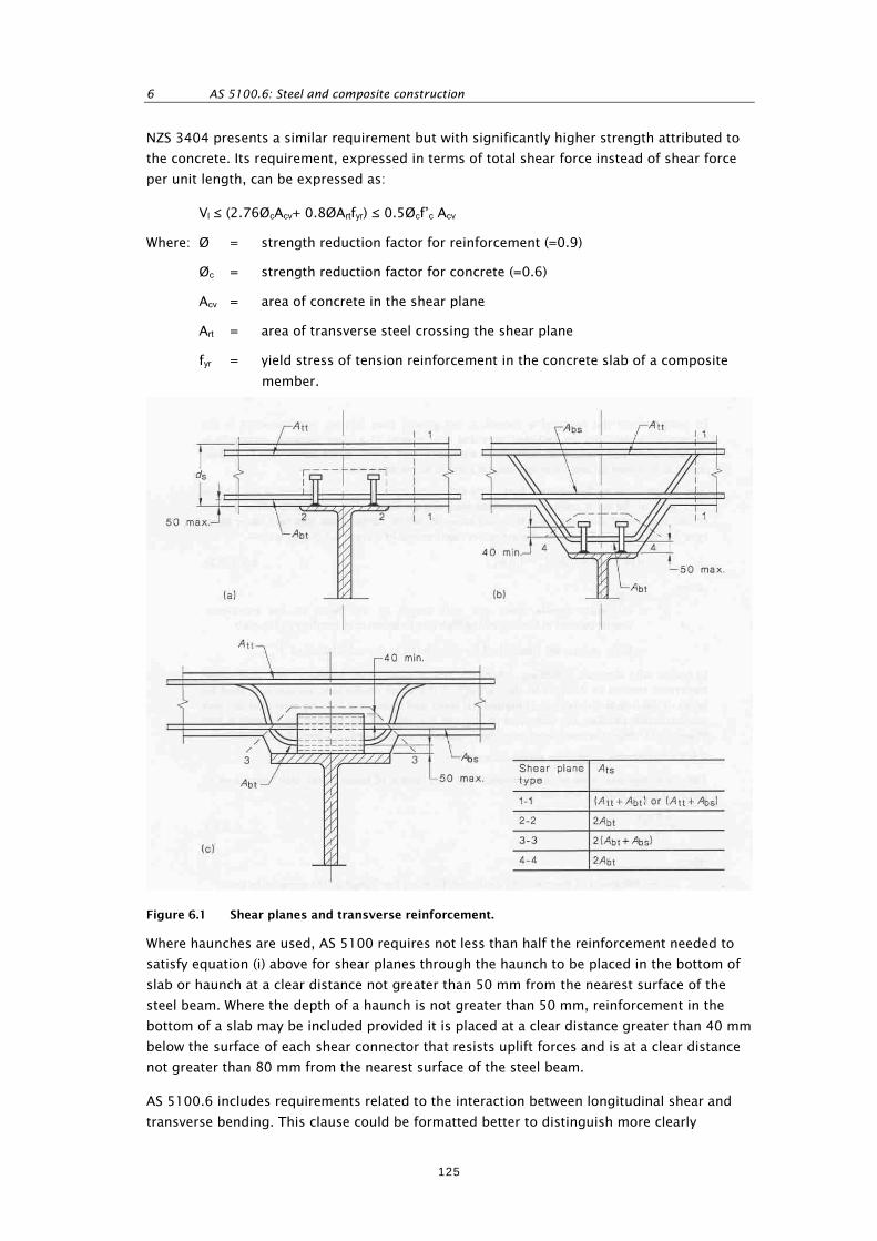
6 AS 5100.6: Steel and composite construction
NZS 3404 presents a similar requirement but with significantly higher strength attributed to
the concrete. Its requirement, expressed in terms of total shear force instead of shear force
per unit length, can be expressed as:
Vl ≤ (2.76ØcAcv+ 0.8ØArtfyr) ≤ 0.5Øcf’c Acv
Where: Ø = strength reduction factor for reinforcement (=0.9)
Øc = strength reduction factor for concrete (=0.6)
Acv = area of concrete in the shear plane
Art = area of transverse steel crossing the shear plane
fyr = yield stress of tension reinforcement in the concrete slab of a composite
member.
Figure 6.1 Shear planes and transverse reinforcement.
Where haunches are used, AS 5100 requires not less than half the reinforcement needed to
satisfy equation (i) above for shear planes through the haunch to be placed in the bottom of
slab or haunch at a clear distance not greater than 50 mm from the nearest surface of the
steel beam. Where the depth of a haunch is not greater than 50 mm, reinforcement in the
bottom of a slab may be included provided it is placed at a clear distance greater than 40 mm
below the surface of each shear connector that resists uplift forces and is at a clear distance
not greater than 80 mm from the nearest surface of the steel beam.
AS 5100.6 includes requirements related to the interaction between longitudinal shear and
transverse bending. This clause could be formatted better to distinguish more clearly
125

REVIEW OF AUSTRALIAN STANDARD AS 5100 ‘BRIDGE DESIGN’ WITH A VIEW TO ADOPTION. VOLUME 2
between requirements for slabs without haunches and those for slabs with haunches, and
between shear planes passing through the full depth of the slab and shear planes that do not
pass through the full depth of the slab. These requirements include:
For beams where the shear planes pass through the full depth of the slab, no account
need be taken of the interaction between longitudinal shear and transverse bending.
In unhaunched slabs, where the design loads at the ULS cause transverse tension in the
slab in the region of the shear connectors, account is to be taken of the effect of this on
the strength of shear planes that do not cross the whole depth of the slab (eg plane 2–2
in figure 6.1.) In this case, equation (i) above is to be replaced by the following equation:
v*Lp ≤ Ø(0.9us + 1.4Abvfry)
Where: Abv = cross-sectional area of transverse reinforcement per unit length of
beam placed in the bottom of the slab or haunch at clear distance not
greater than 50 mm from the nearest surface of the steel beam, and at
a clear distance of not less than 40 mm below the surface of each shear
connector that resists uplift forces, but excluding the bottom
reinforcement provided for flexure
Where design loads at the ULS can cause transverse compression in the slab in the region
of the shear connectors, account may be taken of the beneficial effect of this on the
strength of shear planes that do not cross the whole depth of the slab. For this case,
equation (i) may be replaced by the following equation:
v*Lp ≤ Ø(0.9us + 0.7 Abvfry + 1.6N*t )
Where: N*t = minimum tensile force per unit length of the beam in transverse
reinforcement in the top of the slab due to transverse bending in the
slab
In beams with haunches, where the design loads at the ULS cause transverse tension in
the slab in the vicinity of the shear connectors, no account need be taken of the
interaction between longitudinal shear and transverse bending provided the slab
reinforcement satisfies the definition of Abv and the sides of the haunch are outside a line
drawn at 45o from the outside edge of the shear connectors.
AS 5100 also requires haunches to have a minimum area of transverse reinforcement of not
less than 0.4su/fry, where u is the length of the shear plane around the connectors (ie for
shear planes type 3–3 and 4–4 in Figure 6.1.)
Providing all other requirements for transverse reinforcement for longitudinal shear are
satisfied, AS 5100.6 allows transverse reinforcement for shear planes passing vertically
through the slab to be curtailed assuming the shear force per unit length varies linearly from
zero at midway between the beam centrelines or a free edge, to a maximum adjacent to the
beam shear connectors.
6.6.2.7 Requirements given in NZS 3404, not included in AS 5100.6
Deflections
NZS 3404 specifies several SLS checks, including that the calculation of deflection of
composite members under short- plus long-term SLS loads takes into account the effects of
concrete shrinkage and creep, and increased flexibility due to interfacial slip. Short- and long-
term deflection limits should comply with the recommendations of the loading standard.
126

6 AS 5100.6: Steel and composite construction
Although not covered in section 6 of AS 5100.6, section 18 of AS 5100.2 requires creep and
shrinkage effects to be included in serviceability checks for stresses, cracking and deflection.
Composite slab design
NZS 3404 requirements include the following:
Slabs are to be adequately reinforced to support all specified loads and to control
cracking both parallel and transverse to the composite beam span.
Reinforcement parallel to the beam span is to be anchored by embedment into concrete
that is in compression.
Minimum reinforcement for each purpose is to be as specified in an appropriate design
procedure or standard.
In regions of composite beams subject to inelastic earthquake loading effects, the
contribution of the concrete to resisting longitudinal splitting is to be neglected in
calculating the amount of transverse reinforcement required.
Composite floor slabs are to be designed and detailed, where required, to transfer
horizontal seismic–induced diaphragm shear actions into the supporting beams in
accordance with the requirements of NZS 3101. These shear actions are to be resisted by
suitable shear connections or by encasement of the steel section. Design actions induced
in shear connectors by seismic–induced diaphragm effects are to be added to the design
actions arising from composite action using the appropriate load combinations from the
loadings standard.
Slab reinforcement requirements are covered elsewhere in AS 5100.
Composite action through the encasement of sections
NZS 3404 includes requirements related to achieving composite action through the
encasement in concrete of steel sections.
Steel beam geometric requirements
NZS 3404 specifies geometric requirements for the steel section (ratio of flange breadth to
thickness, and the ratio of the distance from the compression flange to the plastic neutral
axis to web thickness) based on whether the positive or negative moment regions are being
considered and on the extent of plastic rotation to be accommodated. Also, web stiffeners,
where required, are to be provided in the negative moment regions of continuous beams.
Lateral restraint
NZS 3404 requires the design to take into account the lateral restraint available to the steel
beam at each stage of construction.
Limits of use of partial composite action
NZS 3404 requires that no composite action is assumed when:
in computing the moment capacity at the ULS, the nominal capacity of the shear
connectors between the point of maximum moment and point of zero moment is less
than 50% of the lesser of 0.85f’c bect and Afy
in computing deflections for the SLS, the nominal capacity of the shear connectors
between the point of maximum moment and point of zero moment is less than 25% of
the lesser of 0.85f’c bect and Afy.
127
REVIEW OF AUSTRALIAN STANDARD AS 5100 ‘BRIDGE DESIGN’ WITH A VIEW TO ADOPTION. VOLUME 2
(where bec is the slab effective width, and t its thickness, and A is the area of the steel
section).
Special seismic requirements for inelastic action
NZS 3404 requires category 1 or 2 seismic resisting members to be designed for a total
longitudinal shear on the interface between the slab and the beam based on the strain
hardened capacity of any steel yielding in tension. The contribution of concrete to the
resistance of longitudinal splitting of the slab is also to be ignored within the yielding regions
of these members. Specific provisions are also given for the design of positive and negative
moment regions.
End connections
End connections are to be proportioned to transmit the total end reaction of the composite
beam, and are to be designed to the requirements of NZS 3404 section 12.9 when subject to
earthquake loads.
6.6.3 Suitability and actions required to enable adoption
Providing the ratio of the ULS loading to the SLS loading acting on the composite section does
not exceed 1.8 (=1/0.55), section 6 of AS 5100.6 is considered to be generally suitable for
adoption for the design of composite beams not subject to seismic actions. (The maximum
ULS load factor for live load in AS 5100.2 is 1.8 so this condition will normally be satisfied if
the AS 5100.2 load factors are adopted.) However, if AS 5100.6 were adopted, supplementary
documentation would be needed to incorporate the seismic design requirements contained
within the corresponding section of NZS 3404.
The treatment of detailing of shear connectors is more comprehensive in AS 5100.6, and the
requirements for spacing of shear connectors easier to apply when the design loading
involves moving loads.
AS 5100.6 equation 6.6.4.4(2) is incorrect and requires correction. Also, the characteristic
shear capacities for channel shear connectors given in table 6.6.4.5 appear high compared
with the strengths that would be derived from NZS 3404. If AS 5100.6 were adopted these
would need to be reviewed and amended if appropriate.
There is a significant difference between AS 5100.6 and NZS 3404 in the calculation of
strength associated with the design of transverse reinforcement. If AS 5100.6 were adopted,
a review of this aspect would be required with a view to retaining the higher strength
required by NZS 3404, if appropriate.
It AS 5100.6 were adopted the following aspects would need to be incorporated through
supplementary documentation:
a check on the maximum steel stress in tension reinforcement over support regions due
to SLS loads
a correction to the method of calculation of the compression force generated in the
concrete deck slab when the plastic neutral axis lies close to or below the interface
between the deck slab and the steel beam.
Both AS 5100.6 and NZS 3404 present requirements relating to the use of profiled metal
sheeting as permanent formwork for the deck slab. The use of profiled metal sheeting as a
permanent formwork for concrete deck slabs constructed compositely with supporting steel
128

6 AS 5100.6: Steel and composite construction
girders is not appropriate for highway bridge construction, as there is the potential for
crevice corrosion at the location where the shear connectors are welded to the steel girders.
If AS 5100.6 were adopted, the clauses relating to the use of profiled metal sheeting in
composite girder construction would need to be deleted and its use in this application not
encouraged.
The use of the same symbols to represent both ULS and serviceability load effects in
AS 5100.6 (eg v*L, in clauses 6.6.3.3 and 6.6.3.4) should be changed.
The AS 5100.6 clause 6.6.5.3 paragraph at the top of page 104 appears to be either
misplaced or redundant. It is a repeat of the last paragraph on page 102 and should be
appropriately located or deleted.
6.7 Composite box girders
6.7.1 Outline of coverage
The coverage of section 7 of AS 5100.6 encompasses the following:
design of composite box girders
composite box girders without longitudinal stiffeners
flanges in beams with longitudinal stiffeners
webs in beams with longitudinal stiffeners
transverse members in stiffened flanges
diaphragms at supports
longitudinal shear
geometric requirements for longitudinal stiffeners.
6.7.2 Variation of requirements from NZS 3404 and the Bridge manual
The foreword to the 1992 edition of NZS 3404 (included in the 1997 edition) explicitly states
the standard is not written for steel box girder design and recommends reference to an
appropriate limit state standard or design procedure for this information. The foreword to
the 1997 edition outlines the nature of significant revisions made to the standard but does
not indicate any change regarding box girder design.
The Bridge manual, recognising this, requires design for these elements to be in accordance
with AS 5100.6 for box girders with composite concrete decks, or otherwise with BS 5400
parts 3, 5 and 10.
6.7.3 Suitability and actions required to enable adoption
Although section 7 of AS 5100.6 has been adopted in the Bridge manual it does not stand
alone, but requires compliance with other relevant parts of the standard. Thus, where other
relevant parts of the standard have been identified in this report to require amendment or
supplementation these changes should also be taken into account when applying section 7.
Since section 7 of AS 5100.6 has already been adopted in the Bridge manual, this section has
not been reviewed in detail as part of this project. In view of the number of errors detected in
other sections of AS 5100.6, a detailed review of section 7 for errors and omissions by an
engineer expert in steel box girder design is recommended.
129

REVIEW OF AUSTRALIAN STANDARD AS 5100 ‘BRIDGE DESIGN’ WITH A VIEW TO ADOPTION. VOLUME 2
6.8 Transverse members and restraints
6.8.1 Outline of coverage
The coverage of section 8 of AS 5100.6 encompasses the following:
general
definitions
particular requirements (to provide restraint)
design of restraints to flexural members
separators and diaphragms
design of restraints to compression members.
6.8.2 Variation of requirements from NZS 3404 and the Bridge manual
While not a separate section within NZS 3404, comparable requirements are to be found in
sections 5 and 6.
6.8.2.1 General
AS 5100.6 states that sufficient transverse members and restraint systems should be
provided between members so that all external loads and load effects can be transmitted to
the supporting structures, and that adequate restraint is provided where such restraint has
been assumed within section 5: ‘Steel beams’.
6.8.2.2 Particular requirements
Unless other arrangements are justified by analysis complying with section 4: ‘Methods of
structural analysis’, AS 5100.6 requires that all beams should be restrained against rotation
about their own axes at each support, and when such restraint is provided by interconnecting
bracing between two or more beams, consideration should also be given to the possibility of
lateral instability of the combined cross-section.
6.8.2.3 Design of restraints to flexural members
AS 5100.6 and NZS 3404 present identical requirements for restraint against lateral
deflection and for parallel restrained members.
For restraint against twist rotation and lateral rotation AS 5100.6 aligns with AS 4100, with
requirements that differ slightly but are essentially equivalent to NZS 3404. The wording of
the AS 5100.6 requirements appears to be a revision of the NZS 3404 wording with some
enhancement.
AS 5100.6 includes requirements for beams restrained by intermediate U-frames, and for
restraint provided by a deck slab, whether or not located at the compression flange level.
NZS 3404 does not present requirements for these situations.
6.8.2.4 Separators and diaphragms
AS 5100.6 and NZS 3404 present almost identical and equivalent requirements for separators
and diaphragms.
6.8.2.5 Design of restraints to compression members
AS 5100.6 and NZS 3404 present almost identical and equivalent requirements for the design
of restraint to compression members.
130

6 AS 5100.6: Steel and composite construction
6.8.3 Suitability and actions required to enable adoption
Section 8 AS 5100.6 is suitable for adoption as is. It directly reflects requirements within
NZS 3404, with enhancement to some of them and extension to aspects that are particularly
applicable to bridges.
6.9 Members subject to axial tension
6.9.1 Outline of coverage
The coverage of section 9 of AS 5100.6 encompasses the following:
design for axial tension
nominal section capacity
tension members with two or more main components
members with pin connections.
6.9.2 Variation of requirements from NZS 3404 and the Bridge manual
This section presents generally identical requirements to section 7 of NZS 3404 except that
section 7 of NZS 3404 also requires compliance with various requirements of section 12.9
related to design for earthquake loads.
6.9.3 Suitability and actions required to enable adoption
If AS 5100.6 were adopted this section would be suitable subject to the inclusion of
supplementary documentation with the seismic design requirements presented in NZS 3404.
6.10 Members subject to axial compression
6.10.1 Outline of coverage
The coverage of section 10 of AS 5100.6 encompasses:
design for axial compression
section capacity
nominal member capacity
laced and battened compression members
compression members back-to-back
composite compression members.
6.10.2 Variation of requirements from NZS 3404 and the Bridge manual
6.10.2.1 Design for axial compression
AS 5100.6 requires N* ≤ Nus and N* ≤ Nuc, where Nus and Nuc are defined as the nominal
section capacity and nominal member capacity respectively. Derived from nominal strengths
factored by strength reduction factors, Nus and Nuc are therefore not nominal strengths but
design strengths, alternatively referred to as dependable strengths. Throughout this section,
the definitions for these capacities should be corrected, adopting appropriate terminology.
Otherwise, the requirements are essentially equivalent to NZS 3404 for non-composite
members. AS 5100.6 also includes composite members within this clause.
131

REVIEW OF AUSTRALIAN STANDARD AS 5100 ‘BRIDGE DESIGN’ WITH A VIEW TO ADOPTION. VOLUME 2
6.10.2.2 Section capacity
AS 5100.6 and NZS 3404 present essentially identical requirements except NZS 3404 notes
that Ns as determined in section 6 is an upper limit for the section capacity which may be
lowered by the slenderness of the web, the category of the member (as an element of seismic
resisting system) or the bending moment distribution, as specified elsewhere in the standard.
6.10.2.3 Nominal member capacity
AS 5100.6 and NZS 3404 present essentially identical requirements.
6.10.2.4 Laced and battened compression members
AS 5100.6 and NZS 3404 present essentially identical requirements except NZS 3404 requires
members resisting earthquake loads to also satisfy requirements of clause 12.9.8 of the
seismic design section.
6.10.2.5 Compression members back-to-back
AS 5100.6 and NZS 3404 present essentially identical requirements except NZS 3404
requires members resisting earthquake loads to also satisfy requirements of clause 12.9.8 of
the seismic design section.
6.10.2.6 Composite compression members
AS 5100.6 provides requirements for the design of concrete filled circular and rectangular
hollow steel compression members, which include the following features:
a requirement for shear connectors to be provided when the interface shear stress
between the steel and concrete exceeds 0.4 MPa
a check for local buckling of the plate
a calculation of the ultimate section capacity utilising different strength reduction factors
for the steel and concrete elements
enhancement of the concrete strength for confinement for circular members
determination of the member ultimate capacity taking slenderness into account.
NZS 3404 on the other hand, requires calculation of the design capacity to be in accordance
with NZS 3101 or other appropriate limit state design procedure, with shear connectors to be
provided when the interface shear exceeds 0.7 MPa. NZS 3404 also provides requirements for
concrete encased steel sections making up column members.
6.10.2.7 Requirements given in NZS 3404, not included in AS 5100.6 – discontinuous
angle, channel and tee section compression members not requiring design for
moment action
In clause 6.6, NZS 3404 allows discontinuous compression members composed of angles,
channels or tee sections, which meet specified conditions, to be designed for compression
load alone in accordance with the requirements of clauses 6.2 and 6.3 of NZS 3404. Neither
AS 5100.6 nor AS 4100 has adopted this provision.
6.10.3 Suitability and actions required to enable adoption
This section is generally suitable for adoption subject to supplementary documentation
incorporating the seismic design requirements of NZS 3404. The definitions of Nus and Nuc
should also be rectified.
132

6 AS 5100.6: Steel and composite construction
6.11 Members subject to combined actions
6.11.1 Outline of coverage
The coverage of section 11 of AS 5100.6 encompasses the following:
general requirements
design actions
section capacity
member capacity
capacity of composite compression members.
6.11.2 Variation of requirements from NZS 3404 and the Bridge manual
6.11.2.1 Overview and general requirements
There is a high degree of similarity between this section of AS 5100.6 and section 8 of
NZS 3404. Some of the following differences flow through all sub-sections.
As in AS 4100, AS 5100.6 clauses generally specify a basic requirement and then an
alternative to AS 1163, which is applicable to doubly symmetric I-sections and rectangular
and square hollow sections. These are defined in clause 5.2.1 as compact. This also applies
to member capacities, for which the form factor is 1.0.
NZS 3404 presents essentially the same set of alternative requirements, but, under clause 8.1
‘General’, outlines a wider range of conditions under which the alternative requirements may
apply. These require, for the application of alternative requirements, that:
the member is either a doubly symmetric I-section or a rectangular or square hollow
section
and either:
the cross-section is compact, or
the plate element slenderness of each flat plate element in uniform or non-uniform
compression does not exceed the tabulated slenderness limits given in the clause
and either:
the member is subject to design axial tension, or
the form factor, kf, is 1.0, or
the design axial compression force, N*, complies with:
25045
9.1* 1 yw
s
f
t
d
N
N
and 0.1
*0
sN
N
Where: N* = design axial compression force
Ns = nominal section axial load capacity
fyw = web yield stress
d1 = clear depth between flanges ignoring fillets or welds
t = thickness (presumed to be of the web).
133
REVIEW OF AUSTRALIAN STANDARD AS 5100 ‘BRIDGE DESIGN’ WITH A VIEW TO ADOPTION. VOLUME 2
NZS 3404 contains a number of definitions and requirements not given in AS 5100.6. These
are definitions of a member and the requirements for lateral restraint, including that a
member subject to combined bending and significant axial actions and containing one or
more yielding regions is to have full lateral restraint. The axial force level considered to be
significant is also defined.
6.11.2.2 Design actions
In addition to the first-order and second-order linear elastic analysis provided by AS 5100.6,
NZS 3404 also allows design bending moments to be determined from first-order or second-
order plastic analysis, as does AS 4100.
6.11.2.3 Section capacity
The AS 5100.6 and NZS 3404 requirements are essentially the same except for differences
when the alternative design provisions apply. For doubly symmetric I-sections and
rectangular and square hollow sections where the form factor kf < 1.0, AS 5100.6 includes an
alternative method for determining the nominal section moment capacity reduced by axial
load.
6.11.2.4 Member capacity
In addition to AS 5100.6’s requirements for in-plane capacity for members analysed using
elastic analysis, NZS 3404 also includes requirements for members analysed using plastic
analysis.
In the derivation of the nominal out-of-plane member moment capacity by the alternative
method for doubly symmetric I-sections, some variation in the definition of terms exist with
the potential to result in different outcomes. The differences in the definitions of Mbox and L
or Lz are as follows:
AS 5100.6 definitions:
Mbox = nominal member capacity without full lateral restraint and with a uniform
distribution of design moment so that αm is unity, determined in
accordance with clause 5.6
L = overall length.
NZS 3404 definitions:
Mbox = the nominal member moment capacity of the segment or member
calculated using αm = 1.0 in accordance with section 5.6 (in NZS 3404).
Lz = the distance between restraints which effectively prevents twist of the
section about its centroid (ie full or partial restraints)
NZS 3404 also limits the nominal out-of-plane member x-axis moment capacity, Mox, to not
exceed the nominal section moment capacity about the principal x axis, Mrx.
In the consideration of biaxial bending capacity for both compression and tension members,
AS 5100 presents requirements which, in NZS 3404, correspond to those for a member that
does not have full lateral restraint, but omits the case of a member with full lateral restraint.
This would appear to be reasonable, as the fully restrained case is unlikely to be subject to
biaxial bending.
134

6 AS 5100.6: Steel and composite construction
6.11.2.5 Capacity of composite compression members
AS 5100.6 provides requirements for the design of composite compression members made
up of concrete filled circular and rectangular hollow steel sections for uniaxial and biaxial
bending. NZS 3404 does not provide equivalent provisions, simply requiring the calculation
of design capacity to be in accordance with NZS 3101 or other appropriate limit state design
procedure. NZS 3101 does not present a procedure for biaxial bending design.
6.11.3 Suitability and actions required to enable adoption
Section 11 of AS 5100.6 is suitable for adoption. If AS 5100.6 were adopted supplementary
document would need to be prepared to incorporate the NZS 3404 requirement for plastically
yielding elements to have full lateral restraint.
If AS 5100.6 were adopted, the desirability of limiting Mox to not exceed Mrx, and the
significance of the difference in definitions used by AS 5100 and NZS 3404 in the
determination of member out-of-plane capacity by the alternative method would need to be
investigated. If appropriate, an amendment to limit Mox and to the definitions would need to
be incorporated in supplementary documentation.
6.12 Connections
6.12.1 Outline of coverage
The coverage of section 13 of AS 5100.6 encompasses the following:
general requirements
definitions
particular requirements for connections
deductions for fastener holes
design of bolts, rivets and pins
design of welds.
6.12.2 Variation of requirements from NZS 3404 and the Bridge manual
6.12.2.1 General
The initial statement of general requirements for connections is the same in AS 5100.6 and
NZS 3404, except NZS 3404 extends the statement to include requirements for connections
to comply with provisions related to seismic design and to the design of composite members.
Connections should be capable of achieving any ductility demand required by the seismic
design section.
NZS 3404 presents a classification of connections, setting out requirements for:
connections in rigid construction
connections in semi-rigid construction
connections in simple construction
connections in structures analysed by the method of elastic analysis with moment
redistribution
connections in structures analysed by the plastic method.
135

REVIEW OF AUSTRALIAN STANDARD AS 5100 ‘BRIDGE DESIGN’ WITH A VIEW TO ADOPTION. VOLUME 2
NZS 3404’s requirement for connections and the adjacent areas of members to be designed
by distributing the design actions in accordance with four requirements is also included in
AS 5100.6, but is located not so appropriately in section 4, ‘Methods of structural analysis’.
6.12.2.2 Particular requirements for connections
Both AS 5100.6 and NZS 3404 present similar requirements for connections to possess
capacities exceeding a minimum proportion of the connected members’ ‘design capacity’. In
general, AS 5100.6 sets a markedly higher standard for the minimum strength of connections
than does NZS 3404, but does not define a minimum moment for members subject to axial
compression other than to require the consideration of actual eccentricity, initial
imperfections and second-order deformations.
NZS 3404 also includes minimum requirements for connections subject to earthquake loads
or effects.
The term ‘design capacity’ is not defined in AS 5100.6, but in NZS 3404 is defined as the
member’s ‘nominal capacity’ factored by the appropriate strength reduction factor, and is
alternatively known as the dependable capacity. AS 5100.5 similarly defines design strength
as the ultimate strength modified by the strength reduction factor.
AS 5100.6 requires splices in main members to be made either by use of welding or by high-
strength friction-grip bolting, whereas NZS 3404 requires these forms of connection or fitted
bolts to be used where slip at the SLS must be avoided. NZS 3404 also sets out requirements
for when fully tensioned bolts should be used. Where joints are subject to vibration, or
repeated impact loading, NZS 3404 requires high-strength friction-type joints, locking devices
or welding to be used.
AS 5100.6 requires splices in compression members to be located as near as practical to
points of effective lateral support.
NZS 3404 requires that when using sections 6 and 7 of the standard for the design of
connection components carrying compression or tension, the compression member section
constant, αb, is to be taken as 0.5, and the net area, An, is to be determined by means of a
rational analysis which accounts for the distribution of the axial force into the component.
6.12.2.3 Deductions for fastener holes
AS 5100.6 and NZS 3404 present similar requirements except that in addition NZS 3404
requires when design loads or effects from a member are applied to a hollow section at a
connection, that consideration is given to the local effect on the hollow section.
6.12.2.4 Design of bolts, rivets and pins
Bolts
NZS 3404, in addition to the provisions of section 9.3 ‘Design of bolts’, requires the design
of bolts to comply with the requirements for bolts within section 12 ‘Seismic design’, where
appropriate.
AS 5100.6 includes the following additional particular requirements for bolts:
Locking of nuts: where a bolt is subject to impact, vibration or tensile force, the nut is to
be effectively locked in position after tightening.
136
6 AS 5100.6: Steel and composite construction
Minimum number of bolts: bolted connections, except in light bracing members and
railings, are to contain not less than two bolts.
Size of fasteners: fasteners for load-carrying members are not to be less than 16 mm in
diameter. The diameter of fasteners also should not exceed twice the thickness of the
thinnest part being connected, (this does not apply to filler plates). The diameter of
fasteners in load-carrying angles is not to be greater than ¼ of the width of the leg in
which they are placed.
NZS 3404 allows the use of quenched and tempered steel, designated for general structural
use, in splice cover plates for fully bolted column splices. This is subject to the coefficient in
the equation for calculation of the nominal bearing capacity of the ply being reduced from
3.2 to 1.1.
For friction type connections, AS 5100.6 allows the slip factor, μ, to be taken as 0.35 for
abrasive blast-cleaned steel surfaces coated with zinc silicate coatings, whereas in NZS 3404
this finish would fall within the category of requiring a value to be determined based on test
evidence.
Pins
AS 5100.6 makes it clear the design of pins is to be considered at the ULS. This is not clear in
the provisions of NZS 3404.
For a ply in bearing against a pin, AS 5100.6 allows the bearing capacity to be assessed as for
a bolt, (ie Vb ≤ 3.2 dftpfup, and Vb ≤ aetpfup), whereas NZS 3404 requires the bearing capacity to
be assessed by the same equation as for a pin, (ie Vb = 1.4kp dftpfup, where kp = either 1.0 or
0.5). It can be seen from these equations that, so long as edge distance, ae, does not
constrain the bearing capacity, AS 5100.6 will result in a much higher bearing capacity being
assessed for a ply than will NZS 3404.
In both standards it would seem to be an anomaly that the bearing capacity of a pin without
rotation is very much less than that of a bolt.
Rivets
AS 5100.6 requires riveted connections to be designed as for bolted connections. NZS 3404
does not present requirements for riveted connections.
6.12.2.5 Design of welds
General
AS 5100.6 specifies general requirements covering:
welding to comply with AS/NZS 1554
minimisation of stresses and distortion due to the contraction of weld metal
the minimisation of overhead welding in field welding
avoidance, wherever possible, of welded connections that produce tensile stresses
through the thickness of a plate
weld quality to be either GP or SP as specified in AS/NZS 1554.1 and to be specified on
the drawings.
137

REVIEW OF AUSTRALIAN STANDARD AS 5100 ‘BRIDGE DESIGN’ WITH A VIEW TO ADOPTION. VOLUME 2
NZS 3404 also notes that higher weld quality may be required in some situations as specified
by section 10: ‘Fatigue’ and provides guidance on the selection of weld category.
Definitions
The ‘definitions’ in AS 5100.6 are generally included in NZS 3404. Some of the material
presented under the heading ‘Definitions’ are requirements rather than definitions and would
have been better arranged under different headings. The rearrangement of this material from
that adopted by NZS 3404 and AS 4100 has left this section scrambled and is not an
improvement. The insertion of space to separate the dimensions from the angles in 12.6.2.4
(b)(ii) would assist readability and understanding.
Particular requirements for butt welds
AS 5100.6 sets out the following requirements for incomplete penetration butt welds:
They may only be used for longitudinal joints to connect the elements of built up
members, such as girders and columns.
They are not to be used to transmit tensile or compressive loads, or bending moments
about the longitudinal axis of the weld.
Intermittent butt welds are not allowed by AS 5100.6.
AS 5100.6 requires butt welding from one side only to be avoided wherever possible. Where
this is not possible, a backing bar or fluxed backing strip is to be provided, and due
allowance made in the design for the effect of this on fatigue strength.
In addition to the AS 5100.6 provisions for the transition of width or thickness, NZS 3404
requires a more gradual tapering of 1:2.5 where the transition occurs in the yielding region
of category 1 and 2 seismic load resisting members.
Particular requirements for fillet welds
AS 5100.6 presents the following requirements not contained in NZS 3404:
Fillet welds are not to be used in skew joints where the included angle between faces is
less than 60o.
A single fillet weld is not to be used where the weld will be subject to bending about the
longitudinal axis of the fillet.
Intermittent fillet welds are not to be used for splices or connections between members,
or in places where corrosion may be a hazard. They may be used for connections such as
those between internal stiffeners and the plates of a closed box girder.
Wherever practicable, side or end fillet welds, terminating at ends or sides respectively,
of parts of members are to be returned continuously around corners in the same plane as
the main weld for a distance of not less than twice the nominal size of the weld. Such end
returns are to be indicated on the drawings. The terminations of these welds are to be
free from cracks and other defects, and all craters filled in.
The minimum width of a splice plate is to be five times the thickness of the joined
thinner part and not less than 25 mm. Lap joints, joining plates or bars subjected to axial
stress are to be fillet welded along the edge of both lapped parts except where deflection
of the lapped parts is sufficiently restrained to prevent opening of the joint under
maximum loading, in which case welding along one edge only may be used.
138
6 AS 5100.6: Steel and composite construction
Where packing is welded between two members and is less than 6 mm thick, or is too
thin to allow provision of adequate welds or to prevent buckling, the packing is to be
trimmed flush with the edges of the load-carrying element and the size of the welds
along the edges are to be increased over the required sizes by an amount equal to the
thickness of the packing. Otherwise the packing should extend beyond the edges and be
welded to the pieces to which it is fitted.
With the use of intermittent welds largely precluded, AS 5100.6 has omitted the NZS 3404
requirements for built-up members with intermittent fillet welds.
Particular requirements for plug and slot welds
AS 5100.6 restricts the use of plug and slot welds to the transmission of shear in lap joints or
to prevent buckling of lapped parts, whereas NZS 3404 allows their use to join component
parts of built-up members or to prevent out-of-plane buckling of doubler plates in joint panel
zones.
For plug and slot welds, AS 5100 also requires:
The thickness of plug or slot welds, in material less than 16 mm thick, is to be equal to
the thickness of the material. In material over 16 mm in thickness, they are to be half the
thickness of the material, but less than 16 mm.
The minimum size of plug and slot welds in the form of fillet welds around the
circumference of a hole or slot is to be as for fillet welds, while the minimum diameter of
holes for plug welds or width of slots for slot welds is to be:
- 200 mm for plates less than or equal to 12 mm thick (thought to be in error, and
probably meant to be 20 mm)
- 25 mm for plates greater than 12 mm and less than or equal to 20 mm thick
- 30 mm for plates greater than 20 mm and less than or equal to 25 mm thick
- 40 mm for plates greater than 25 mm and less than or equal to 30 mm thick.
The length of a slot for a slot weld is not to exceed 10 times the width of the slot, with
the ends of the slots either semi-circular or with corners rounded to a radius not less
than the thickness of the part containing them.
NZS 3404 merely requires plug and slot welds to be regarded as fillet welds with their
minimum size as for fillet welds and effective length as defined in the section on fillet welds.
Seal welds
NZS 3404 does not present requirements for seal welds. AS 5100.6 requires them to be
specified on the drawings with a size corresponding to the minimum size for a fillet weld for
the thickness of material being connected. Their structural effects should also be taken into
account.
Design of welds
In the strength assessment of butt welds, AS 5100.6 and NZS 3404 both allow the strength of
the weld to be taken as equal to the nominal capacity of the weaker joined part multiplied by
the appropriate strength reduction factor, providing that the welding procedure has been
qualified in accordance with AS/NZS 1554.1 for AS 5100.6, or with either AS/NZS 1554.1 or
AS/NZS 1554.5 for NZS 3404. The strength of incomplete butt welds is to be assessed as for
139

REVIEW OF AUSTRALIAN STANDARD AS 5100 ‘BRIDGE DESIGN’ WITH A VIEW TO ADOPTION. VOLUME 2
a fillet weld. NZS 3404 requires butt welds to be made with welding consumables that will
produce a minimum strength not less than the parent material.
AS 5100.6 and NZS 3404 present essentially the same requirements for the strength
assessment of fillet welds, except for welds connecting category 1 or 2 members in seismic
resisting systems, NZS 3404 requires the nominal tensile strength of the weld material to
exceed that of the members. Both standards also present essentially the same requirements
for the strength assessment of plug and slot welds.
6.12.3 Suitability and actions required for adoption
Section 12 of AS 5100.6 is generally suitable for adoption. If AS 5100.6 were adopted
supplementary documentation would be needed to incorporate the following:
the seismic design requirements contained within the corresponding section of NZS 3404
pin design rules in NZS 3404 are based on tests by HERA and were incorporated in a
2001 amendment. They would therefore be preferred to the rules given in AS 5100.6
splices in compression members between points of lateral support to be designed for a
minimum moment as well as a minimum axial load
consideration of the local effect of the connection of members on hollow sections
consideration of the need for higher weld quality in some situations (eg to provide for
fatigue). The guidance provided by NZS 3404 on weld category selection should also be
retained
an increase in the range of applications for plug welds, as allowed by NZS 3404
a correction to amend the size of plug and slot welds for plates less than 12 mm thick
a requirement for welding consumables for butt welds to produce a minimum strength
not less than the parent metal.
In addition, a review would also need to be undertaken on the capacity of pins. There are
significant differences between AS 5100.6 and NZS 3404 in these requirements and they also
appear to contain an anomaly.
6.13 Fatigue
6.13.1 Outline of coverage
The coverage of section 13 of AS 5100.6 encompasses the following:
general requirements
fatigue loading
design spectrum
exemption from assessment
detail category
fatigue strength
fatigue assessment
punching limitations.
140
6 AS 5100.6: Steel and composite construction
6.13.2 Variation of requirements from NZS 3404 and the Bridge manual
6.13.2.1 General
Basic requirements
Section 13 of AS 5100.6 requires the fatigue assessment to be based on:
the detail category of the construction detail subjected to fluctuating stress, as defined in
clause 13.5.1 of the section
the loading to be used in the fatigue assessment, which is to be made up of the design
spectrum range, as defined in clause 13.3 of the section, and the number of stress cycles
in the design life.
NZS 3404 allows a fracture assessment to be undertaken in accordance with clause 2.6.5 of
the standard as an alternative to the provisions of section 10 of the standard.
Definitions
Within the definitions, AS 5100.6 defines the S – N curve as the limiting relationship between
the number of stress cycles and stress range for a detail category.
Capacity factor
AS 5100.6 specifies the following requirement:
For the reference design condition, the capacity factor (Ø) should be taken as 1.0. The
reference design condition implies the following:
(i) The detail is located on a redundant load path, in a position where failure at that
point alone will not lead to overall collapse of the structure.
(ii) The stress history is estimated by conventional means.
(iii) The load cycles are not highly irregular.
(iv) The detail is accessible for, and subject to regular inspection.
The capacity factor (Ø) should be reduced when any of the above conditions do not apply.
For non-redundant load paths, the capacity factor (Ø) should be taken equal to 0.7.
NZS 3404 presents similar requirements but expresses them a little differently:
If (i) applies, and only one of (ii) to (iv) apply, then Ø is to be reduced to 0.85.
If (i) applies, but none of (ii) to (iv) apply, then Ø is to be taken as less than 0.85 and is to
be determined by rational design.
If (i) doesn’t apply, ie the detail is located on a non-redundant load path, but (ii) to (iv) are
all satisfied, then Ø may be taken as 1.0; if any two of (ii) to (iv) apply, Ø = 0.8; and if one
or none of (ii) to (iv) apply, Ø < 0.8 is to be determined by rational design.
Neither standard expresses these requirements particularly well. NZS 3404 leaving Ø to be
‘determined by rational design’ is not considered to be very satisfactory. Similarly, AS 5100.6
provides no guidance on how Ø is to be reduced when conditions (ii) to (iv) are not met.
141
REVIEW OF AUSTRALIAN STANDARD AS 5100 ‘BRIDGE DESIGN’ WITH A VIEW TO ADOPTION. VOLUME 2
Thickness effect
AS 5100 and NZS 3404 present similar requirements except that AS 5100.6 adopts 1.0 as the
correction factor for shear strength for all plate thickness, whereas NZS 3404 applies the
derived correction factor, ßtf, to the reference shear fatigue strength.
6.13.2.2 Fatigue loading
AS 5100.6 specifies the fatigue design loading and effective number of stress cycles in the
design life to be determined in accordance with AS 5100.2. It also requires the stresses
induced in connections due to out-of-plane bending in main members, misalignment at
bearings etc, to be assessed for fatigue capacity.
NZS 3404 requires the design fatigue load to be derived from the Bridge manual, which is
currently considered to provide inadequate specification of design fatigue loading. Use of the
AS 5100.6 fatigue loading specification is unlikely to be appropriate for New Zealand
conditions either, and work is required in this area to rectify this deficiency for New Zealand
bridge design.
6.13.2.3 Design spectrum
In addition to requiring the design stresses to be determined from an elastic analysis of the
structure, or from the stress history obtained from strain measurements, AS 5100.6 requires
the full stress range to be considered, even if part of the stress range is in compression.
NZS 3404, in its requirements for the fatigue assessment of truss members, fails to define ‘L’
and inappropriately defines ‘d’ as the depth in the plane of the truss. ‘d’ and ‘dy’ are
appropriately defined elsewhere, in the notation.
NZS 3404 includes requirements for the fatigue assessment of truss connections involving
hollow sections This is omitted in AS 5100.6.
6.13.2.4 Detail category
AS 5100.6 and NZS 3404 appear to present identical tables of detail categories, except that
AS 5100.6 fails to highlight what are presented as headings in the description column in
NZS 3404. Highlighting this text as headings would add clarity.
In both standards, detail category 112 (16) is described as having the weld reinforcement
ground flush to the plate surface. What is meant by ‘weld reinforcement’ is not clear. In the
diagram the weld is shown ground flush on the top side but bulging on the plate underside.
In AS 5100.6, the diagrams for detail category 90 (19), (20) and (21), detail 80 (22), detail 71
(23 and (24), detail 50 (25), detail 71 (26), detail 50 (38)/36 (38), detail 100 (41), detail 36
(42), detail 140 (43), detail 90 (44)/71 (44), and detail 71 (45)/56 (45) need to be amended to
show the stress direction arrows correctly.
Again, in detail 90 (21) in both standards, the weld should presumably be shown ground flush.
For detail category 80 (22) in both standards, the butt weld is shown not ground flush with
the plate surfaces. This distinction from the preceding details should perhaps be made in the
description text.
In both standards, for consistency, detail 56 (27)/36 (28) and detail 56 (30)/45 (31) should
be given headings in the description column.
142

6 AS 5100.6: Steel and composite construction
In AS 5100.6, the diagram for detail 71 (36) differs from that in NZS 3404 and does not
appear to be drawn correctly.
In NZS 3404, detail 50 (38) /36 (38), ‘tr’ should be replaced by ‘tf’.
Detail 45 (49) in AS 5100, when compared with the same detail in NZS 3404, appears to be
labelled incorrectly. This detail category should be labelled ‘t ≥ 8 mm’.
6.13.2.5 Fatigue strength
In addition to definitions of fatigue strength for normal stress and for shear stress, AS 5100.6
also includes a definition for fatigue strength for shear stud connectors, which is not
included in NZS 3404.
6.13.2.6 Fatigue assessment
Exemption from further assessment
AS 5100.6 exempts members, connections or details from fatigue checks where the following apply:
The design stress range for the stress condition being checked (ie the normal or shear
stresses as appropriate) is less than the corrected detail category fatigue strength at the
constant amplitude fatigue limit. The clause wording should say: factored by the capacity
reduction factor, ie fn* < Øf3nc, or fs* < Øf3sc, as appropriate.
For normal stresses, where the total stress from permanent and variable loads is
compressive at all times.
In comparison, NZS 3404 exempts any point in a structure from further assessment if all
normal stress ranges are less than the constant stress range fatigue limit. Again the clause
should say: factored by the strength reduction factor, ie less than Øf3.
Constant stress range
AS 5100.6 requires that where the stress ranges of the fatigue load to which a bridge is
subjected are essentially constant in magnitude, or if an effective number of cycles (n) of the
fatigue design stress range, fn* or fs*, has been calculated in accordance with the fatigue
requirements of AS 5100.2, then the detail may be assessed to be acceptable if:
for normal stresses:
0.1)(102
)(36
3*
rnc
n
fx
fn
for shear stresses:
0.1)(102
)(56
5*
rsc
s
fx
fn
Where: frnc = corrected detail category of normal stresses
frsc = corrected detail category for shear stresses
Ø = capacity factor
These definitions from AS 5100 for frnc and frsc could be better worded to make clear that they
are the corrected reference fatigue strengths at 2 x 10⁶ cycles.
143

REVIEW OF AUSTRALIAN STANDARD AS 5100 ‘BRIDGE DESIGN’ WITH A VIEW TO ADOPTION. VOLUME 2
NZS 3404 is less clearly worded, requiring simply that the design stress range (f*) at any
point in the structure subject only to constant stress range cycles should satisfy the following
relationship, with the assumption that fc is the fatigue strength corresponding to the number
of cycles associated with f* :
0.1*
cf
f
Where: fc = fatigue strength corrected for material thickness
Ø = strength reduction factor
Variable stress range
For variable stress range, AS 5100.6 and NZS 3404 present essentially equivalent
requirements. In AS 5100.6, a correction is required to equation 13.7.3(1) – fsnc should read
f3nc. In NZS 3404, a definition is needed for frsc.
Fatigue design life
AS 5100.6 includes a method of assessment for fatigue life appropriate for where an existing
structure is being assessed or a design life other than 100 years is required.
6.13.2.7 Punching limitation
AS 5100.6 and NZS 3404 both require, for the assessment of fatigue in members or
connections, that punched holes are not to be formed in material thicker than 12 mm.
6.13.3 Suitability and actions required to enable adoption
Section 13 of AS 5100.6 is generally suitable for adoption. If AS 5100.6 were adopted
supplementary documentation would need to address the following:
the clarification of clause 13.1.6 ‘Capacity factor’ as discussed under ‘Capacity factor’ in
6.13.2.1 above. An amalgamation of the requirements of AS 5100.6 and NZS 3404 would be a
reasonable approach. An improvement in the way this clause is written would also be helpful
a review of, and probable amendment of, clause 13.2 ‘Fatigue loading’ to achieve
consistency with the design traffic loadings adopted for use in New Zealand
clarification and correction of the detail categories noted in 6.13.2.4 above as requiring
correction
correction of equation 13.7.3(1) and clarification of the definitions for frnc and frsc.
6.14 Brittle fracture
6.14.1 Outline of coverage
The coverage of section 14 of AS 5100.6 encompasses:
general requirements
methods (for selection of steel grade)
notch-ductile range method
design service temperature
material selection
fracture assessment.
144

6 AS 5100.6: Steel and composite construction
6.14.2 Variation of requirements from NZS 3404 and the Bridge manual
6.14.2.1 General
AS 5100.6 sets out a general description of the conditions under which brittle fracture may
be critical.
6.14.2.2 Notch-ductile range method
In addition to the requirements given in AS 5100.6, NZS 3404 also requires welding
consumables and bolts to be selected in accordance with clauses given within the section.
6.14.2.3 Design service temperature
AS 5100.6 provides a map of isotherms of the lowest one-day mean ambient temperatures
for Australia as the basis for deriving the basic design temperature. NZS 3404 provides the
corresponding map for New Zealand.
AS 5100.6 requires that the design service temperature for bridges is taken as 5oC less than
the basic design temperature, whereas NZS 3404 gives more general guidance for structures
subject to especially low ambient temperatures, indicating that for bridges over inland rivers
or structures located in alpine regions, a design service temperature of 5oC less than the
basic design temperature is to be used.
For determining the temperature environment for critical structures, AS 5100.6 refers to the
(Australian) Bureau of Meteorology records, and NZS 3404 refers to the New Zealand National
Institute of Water and Atmospheric Research records.
6.14.2.4 Material selection
Selection of steel type
AS 5100.6 and NZS 3404 present similar tables for the permissible service temperature
associated with different steel types and thicknesses, but with AS 5100.6 allowing slightly
lower temperatures for steel types 3 and 6 and for some thicknesses between 12 and 70 mm.
AS 5100.6 also lists an additional steel type, 7C.
Limitations
In addition to AS 5100.6’s requirements, NZS 3404 also makes reference to fabrication and
erection to comply with the provisions of AS 1554.5 as appropriate.
Modifications for certain applications
In addition to AS 5100.6’s requirements, NZS 3404 includes a requirement for the
permissible temperature to be raised by 10oC above the value tabulated for category 1 and 2
members of seismic resisting systems.
Selection of steel grade
As 5100.6 and NZS 3404 present similar tables relating steel type to the steel grades of
various standards. For the commonly used AS and AS/NZS standards for structural steels,
AS 5100.6 lists a few more grades than are given in NZS 3404. For steel type 3 and steel to
AS 3679.1, AS 5100.6 lists grade 300L15 whereas NZS 3404 lists 300L5, suggesting that this
may be an error in NZS 3404. In AS 5100.6, for steel type 6, the ‘l’ in the steel grades should
be corrected to ‘L’. NZS 3404 also lists steel grades to BS EN 10025 and JIS G 3106, not
included in the AS 5100.6 table.
145

REVIEW OF AUSTRALIAN STANDARD AS 5100 ‘BRIDGE DESIGN’ WITH A VIEW TO ADOPTION. VOLUME 2
6.14.2.5 Fracture assessment
AS 5100.6 requires a fracture assessment to be used for major or critical structures or for
applications outside the range given in the steel type relationship to steel grade table.
NZS 3404 simply allows a fracture assessment as an alternative to the specified approach.
NZS 3404 lists a draft ISO standard as an additional reference for fracture assessment.
6.14.3 Suitability and actions required to enable adoption
Section 14 of AS 5100.6 is generally suitable for adoption. If AS 5100.6 were adopted
supplementary documentation would be needed to incorporate the following NZS 3404
provisions:
requirements for welding consumables and bolts
the map of isotherms for New Zealand and reference to the National Institute of Water
and Atmospheric Research as the source for information on abnormally low local ambient
temperatures.
under ‘Limitations’, the inclusion of AS 1554.5 as a standard to be complied with where
appropriate
requirements for the permissible temperature to be raised for category 1 and 2 members
of seismic resisting systems
inclusion of the BS EN 10025 and JIS G 3106 steel grades as these may also be
encountered in New Zealand.
6.15 Testing of structures or elements
6.15.1 Outline of coverage
The coverage of section 15 of AS 5100.6 encompasses:
general requirements
definitions
test requirements
proof testing
prototype testing
report of tests.
6.15.2 Variation of requirements from NZS 3404 and the Bridge manual
With several very minor exceptions, the requirements of AS 5100.6 and NZS 3404 are
essentially the same.
Under test requirements, AS 5100.6 requires the test load to be applied for at least five
minutes. No test load duration is specified in NZS 3404.
AS 5100.6 requires the test load to be equal to the design load for the relevant limit state as
determined from AS 5100.2. NZS 3404 refers to the loadings standard, and for bridges, to
the Bridge manual, as the source for the design load.
NZS 3404, for both proof testing and prototype testing includes acceptance criteria for
testing for strength and ductility in seismic applications. The acceptance criteria for proof
146
6 AS 5100.6: Steel and composite construction
testing make reference to a test procedure set out in NZS 4203 volume 2, appendix C4.A,
which does not appear to have been included in the new loading standard, AS/NZS 1170.
Neither AS 5100.6 nor NZS 3404 advises or requires incremental and all the other procedural
steps set out in the Bridge manual.
6.15.3 Suitability and actions required to enable adoption
Section 15 of AS 5100.6 is generally suitable for adoption. If AS 5100.6 were adopted
supplementary documentation would be needed to incorporate the following provisions:
the requirement for the test load to be applied for at least five minutes
references to the Bridge manual as the source for the design loading to be used as the
test load
reference to the Bridge manual for load application, instrumentation and procedure
(section 6.6.3).
acceptance criteria for strength and ductility testing for seismic applications.
6.16 Elastic resistance to lateral buckling (appendix A)
6.16.1 Outline of coverage
The coverage of appendix A of AS 5100.6 encompasses:
general (covering the potential conservatism of the design requirements of the standard,
and options for achieving less conservatism)
segment restrained at both ends
segment restrained at one end
reference elastic buckling moment
effects of end restraints
references.
6.16.2 Variation of requirements/guidance from NZS 3404 and the Bridge manual
Throughout appendix A, where AS 5100.6 uses L, the segment length, in equations, NZS
3404 uses Le = ktL, the segment effective length. (AS 4100 aligns with AS 5100.6 in this.)
Segments restrained at both ends, segments unrestrained at one end and effects of end
restraints
AS 5100.6 and NZS 3404 present similar requirements for these aspects.
Reference elastic buckling moment (Mo)
AS 5100.6 and NZS 3404 present similar procedures for calculating this parameter.
AS 5100.6 equation A4(1) presents the initial √ applying only to the numerator, whereas
NZS 3404 (and AS 4100) apply the √ to both the numerator and denominator, suggesting the
equation in AS 5100.6 may be in error.
6.16.3 Suitability and actions required to enable adoption
Appendix A is considered to be suitable for adoption, subject to confirmation of the
following:
147
REVIEW OF AUSTRALIAN STANDARD AS 5100 ‘BRIDGE DESIGN’ WITH A VIEW TO ADOPTION. VOLUME 2
the use of L, the segment length, instead of Le = ktL, the segment effective length, as
appropriate
equation A4(1) being correctly formulated.
6.17 Strength of stiffened web panels (appendix B)
6.17.1 Outline of coverage
The coverage of appendix B of AS 5100.6 encompasses:
yielding check
buckling check.
6.17.2 Variation of requirements/guidance from NZS 3404 and the Bridge manual
AS 5100.6 and NZS 3404 present essentially identical requirements except that in AS 5100.6
equation B2(1) N*w /(ØNwo) is added instead of subtracted as in NZS 3404. (AS 5100.6 aligns
with AS 4100 in this.)
6.17.3 Suitability and actions required to enable adoption
Appendix B is considered to be suitable for adoption subject to equation B2(1) being
confirmed as correctly formulated.
6.18 Second order elastic analysis (appendix C)
6.18.1 Outline of coverage
The coverage of appendix C of AS 5100.6 encompasses:
analysis
design bending moment.
6.18.2 Variation of requirements/guidance from NZS 3404 and the Bridge manual
6.18.2.1 Analysis
In addition to AS 5100.6’s requirement, NZS 3404 presents two exceptions: allowing second
order effects to be neglected if the buckling load factor for the frame is greater than 10, and
allowing the changes in effective stiffness of members due to axial loads to be neglected if
the frame buckling load factor is less than 5. In applying the appendix to seismic resisting
frames, NZS 3404 also requires P – delta effects to be considered in accordance with the
loading standard.
6.18.2.2 Design bending moment
AS 5100.6 and NZS 3404 present similar requirements but with subtle wording differences
that change the meaning.
Both AS 5100.6 and NZS 3404 provide three alternative methods for determining the design
bending moment. AS 5100.6, by changing ‘or’ to ‘and’ at the end of method ‘b’ combines
method ‘b’ with method ‘c’.
148
6 AS 5100.6: Steel and composite construction
AS 5100.6 (and AS 4100) omit the qualifying wording to the use of method ‘a’: ‘if it outputs
P – δ and P – delta effects’. There is the implication that if this method does not provide these
outputs, it should not be used, which has been lost through removal of these words.
6.18.3 Suitability and actions required to enable adoption
The wording of appendix C has been amended over time, via AS 4100, from the original
wording presented in NZS 3404. There are subtle changes in meaning that may not have
been intended or which may not be appropriate. If AS 5100.6 were adopted it would be
necessary for appendix C to be subjected to a detailed review. Rewording clause C2 would be
desirable to ensure that it correctly reflects the intended requirements and will be
appropriately interpreted. While the exemptions of NZS 3404 clause E1 may not be essential,
unless they have been omitted from AS 5100.6 on the grounds of being inappropriate, their
inclusion would appear to simplify design in some instances.
6.19 Eccentrically loaded double-bolted or welded single angles in trusses (appendix D)
6.19.1 Outline of coverage
Appendix D of AS 5100.6 outlines the design of single angle web compression members in
trusses that are connected at their ends through one leg of the angle.
6.19.2 Variation of requirements from NZS 3404 and the Bridge manual
This AS 5100.6 appendix presents almost identical requirements to NZS 3404 clause 8.4.6,
but NZS 3404, through its clause 8.1.6, limits the applicability of this design approach to
compression members with slenderness ratios of L/ry < 150.
The AS 5100.6 appendix fails, in the limitation on L/t, to define where the term ßm is derived
from. Also, in the paragraph below equation D2, there is a typographical error: ‘N*e’ should
read ‘N*e’.
For angles on opposite sides of the truss chord, AS 5100.6 (and AS 4100) define e as: e = ec +
et, whereas NZS 3404 defines e as: e = ec. NZS 3404 is considered to be correct, and
AS 5100.6 incorrect, on the basis that the AS 5100.6 expression derives a moment that is
carried by both the tension and compression angles, not by the compression angle alone.
6.19.3 Suitability and actions required to enable adoption
This appendix is suitable for adoption subject to:
review of the need to limit applicability to compression members with slenderness ratios
of L/ry < 150
correction of ‘N*e’ to ‘N*e’
confirmation or correction of the expression for ‘e’ for the case of angles on opposite
sides of the truss chord.
149
REVIEW OF AUSTRALIAN STANDARD AS 5100 ‘BRIDGE DESIGN’ WITH A VIEW TO ADOPTION. VOLUME 2
6.20 Nominal moment capacity for composite sections under sagging moment (appendix E)
6.20.1 Outline of coverage
Appendix E of AS 5100.6 provides guidance on the determination of the nominal moment
capacity of sections composed of concrete deck slabs acting compositely with steel beams
using plastic theory. Three cases are presented:
compression zone is entirely within the concrete slab
compression zone extends into the top flange of the steel section
compression extends into the steel beam beyond the top flange.
6.20.2 Variation of guidance from NZS 3404 and the Bridge manual
Appendix E is referred to in AS 5100.6 clause 6.3.3. As noted earlier in reviewing that clause:
the methods of calculating the plastic moment capacity, in determining the concrete
compression force, appear to assume the full depth of concrete in compression to be
stressed to 0.85 f’c, instead of a reduced depth as given in NZS 3101 clause 7.4.2.7 for
determination of the equivalent rectangular stress block. NZS 3404 similarly neglects to take
this into account.
6.20.3 Suitability and actions required to enable adoption
Although the simplified method of calculation in appendix E is not consistent with NZS 3101
it is suitable for adoption. In view of the level of accuracy in the effective slab rules the
approximate concrete stress block appears satisfactory and the calculation method is well
established.
6.21 Interaction curves for composite columns (appendix F)
6.21.1 Outline of coverage
Appendix F of AS 5100.6 outlines the derivation of the interaction curve for axial load acting
in conjunction with uniaxial bending on a composite section composed of concrete infill
inside a steel tube.
6.21.2 Variation of requirements from NZS 3404 and the Bridge manual
NZS 3404 does not present comparable requirements. It refers to NZS 3101 for derivation of
the design capacity, but NZS 3101 does not provide requirements for concrete infilled steel
tubes acting compositely.
6.21.3 Suitability and actions required to enable adoption
Appendix F appears suitable for adoption for the design of segments of concrete infilled steel
tube columns where full composite action can be assumed based on satisfying the
requirements of AS 5100.6 clause 10.6.1.
6.22 Fabrication (appendix G)
6.22.1 Outline of coverage
Appendix G of AS 5100.6 encompasses the following:
general requirements, outlining when material or fabrication may be rejected or accepted
150
6 AS 5100.6: Steel and composite construction
material
fabrication procedures
tolerances.
6.22.2 Variation of requirements from NZS 3404 and the Bridge manual
This AS 5100.6 appendix is largely identical to NZS 3404 section 14.
6.22.2.1 Material
AS 5100.6 omits the requirement in NZS 3404 clause 12.4.1.1 that the actual yield stress of
steel, as recorded on the certified mill test report or test certificate, should not exceed the
maximum value specified by table 12.4 of the seismic design section.
6.22.2.2 Fabrication
In the application of heat to introduce or correct camber, sweep and out-of-straightness,
AS 5100.6 limits the maximum temperature to 600oC, compared with 650oC allowed by
NZS 3404. AS 5100.6 also states that to avoid loss of ductility, repeated cycles in the 350oC
to 450oC range should be avoided.
The AS 5100.6 notes to the table of maximum cut surface roughness make reference to
AWRA surface replicas and to a technical note, which is presumed to reflect a renaming of the
Welding Technology Institute of Australia (WTIA) referred to by NZS 3404. AS 5100.6 also
allows that provided there is no loss of the effective cross-section, defects of up to 3 mm may
be ground out over 10 times the defect depth.
NZS 3404 requires pins and holes in pinned connections to be finished so that forces are
distributed evenly to the joint plies. This provision is not included in AS 5100.6.
6.22.2.3 Tolerances
With respect to the tolerances on the cross-section of rolled sections or plates, AS 5100.6
requires that after fabrication these are to comply with the tolerances specified by
AS/NZS 3678 or AS/NZS 3679 as appropriate. NZS 3404 lists a wider range of standards,
including British and Japanese standards, which are to be complied with depending on the
country of source of the steel.
For the tolerances on the cross–section of built up sections, AS 5100.6 adopts tighter
tolerances in a number of instances than permitted by NZS 3404.
Unlike NZS 3404, AS 5100 does not distinguish between different sections of beams. For
camber, in addition to the tolerance not being greater than L/1000, AS 5100.6 limits the
tolerance to not being greater than 10mm. For sweep, AS 5100.6 limits the tolerance to the
greater of L/1000 or 3 mm, which for beams longer than 3.0 m will generally be more
restrictive than in NZS 3404.
AS 5100.6 also includes tolerances for plate panels and for compression flange and web
stiffeners, not covered by NZS 3404.
6.22.3 Suitability and actions required to enable adoption
Appendix G of AS 5100.6 is suitable for adoption subject to the addition of the NZS 3404
requirement limiting the yield stress of steel where required to satisfy seismic design
requirements.
151
REVIEW OF AUSTRALIAN STANDARD AS 5100 ‘BRIDGE DESIGN’ WITH A VIEW TO ADOPTION. VOLUME 2
6.23 Erection (appendix H)
6.23.1 Outline of coverage
Appendix H of AS 5100.6 encompasses the following:
general requirements, related to safety during erection, equipment support and reference
temperature
erection procedures
concrete-filled compression members.
6.23.2 Variation of requirements from NZS 3404 and the Bridge manual
Appendix H is largely identical to NZS 3404 section 15.
6.23.2.1 General
AS 5100.6 omits NZS 3404 section 15.1.1 on rejection of an erected item.
6.23.2.2 Concrete-filled compression members
AS 5100.6 requires the surface of the steel member in contact with the concrete filling to be
unpainted and free from deposits of oil, grease and loose scale or rust. NZS 3404 does not
include provisions related to the construction of concrete-filled compression members.
6.23.2.3 Other matters included in NZS 3404, omitted from AS 5100.6
In addition to the coverage in common with AS 5100.6, NZS 3404 also gives coverage to the
following:
tolerances, in relation to the following:
- location of anchor bolts
- column bases – position in plan, level and full contact
- plumbing of a compression member
- column splice
- level and alignment of a beam
- position of a tension member
- overall building dimensions
inspection of bolted connections
grouting at supports.
6.23.3 Suitability and actions required to enable adoption
Appendix H is generally suitable for adoption. However, if AS 5100.6 were adopted, material
contained in NZS 3404 and omitted from AS 5100.6 would need to be incorporated through
supplementary documentation.
6.24 Modification of existing structures (appendix I)
6.24.1 Outline of coverage
Appendix I of AS 5100.6 encompasses the following:
general
152
6 AS 5100.6: Steel and composite construction
materials
cleaning
special provisions (related to welding).
6.24.2 Variation of requirements from NZS 3404 and the Bridge manual
Appendix I is identical in content to NZS 3404 section 16 except for the addition of one
further special provision related to welding repair and strengthening, which states: ‘For
requirements not specified in AS/NZS 1554.5, such as straightening and repairing existing
structures, see ANSI/AWS D1.1-96’.
6.24.3 Suitability and actions required to enable adoption
Appendix I is suitable for adoption.
6.25 NZS 3404 material not included within AS 5100.6
6.25.1 NZS 3404 sections not included
The following sections of NZS 3404, potentially relevant to bridge design, do not appear to
receive significant coverage in AS 5100.6:
Section 12: Seismic design
Appendix A: Referenced documents. (A much more limited listing appears in AS 5100.6
clause 1.2)
Appendix B: Maximum levels of ductility demand on structural steel seismic-resisting
systems
Appendix C: Corrosion protection. (Brief coverage only in AS 5100.6 clause 3.7.)
Appendix D: Inspection of welding to AS/NZS 1554.1
Appendix F: Moment amplification for a sway member
Appendix G: Braced member buckling in frames
Appendix K: Standard test for the evaluation of slip factor
Appendix L: Inspection of bolt tension using a torque wrench
Appendix M: Design procedure for bolted moment-resisting endplate connections
Appendix N: Section properties to use in ULS and SLS calculations for deflection
Appendix P: Alternative design method.
6.25.2 Recommendations in respect to omitted NZS 3404 material
6.25.2.1 Section 12: Seismic design
As seismic design is usually a significant, if not dominant, consideration in the design of
bridges in New Zealand, except perhaps in the zones of lowest seismicity, it is essential that
the design standard for bridges in New Zealand include requirements for seismic design.
If AS 5100.6 were adopted, supplementary documentation would need to be prepared to
incorporate requirements for seismic resistant design. This supplementary documentation
may be derived from NZS 3404, and if that were so, would also draw on NZS 3404
appendices B and N.
153
REVIEW OF AUSTRALIAN STANDARD AS 5100 ‘BRIDGE DESIGN’ WITH A VIEW TO ADOPTION. VOLUME 2
6.25.2.2 Appendix A: Referenced documents
As noted previously, NZS 3404 references a number of New Zealand standards relating to
concrete and its reinforcement, qualification tests for metal arc welders, several AS standards
not referenced by AS 5100.6 that would appear to be relevant to steel bridge design and
construction, and a range of American, British, Japanese and international standards. With the
exception of one American welding standard, AS 5100.6 references only AS and joint AS/NZS
standards.
If AS 5100.6 were adopted, supplementary documentation would be needed to incorporate
the reference to the range of standards relevant to steel bridge design and construction in
the New Zealand environment. Appendix A of NZS 3404 provides a basis for this
supplementary documentation.
6.25.2.3 Appendix B: Maximum levels of ductility demand on structural steel seismic
resisting systems
Refer to section 6.25.2.1
6.25.2.4 Appendix C: Corrosion protection
As discussed previously in sections 6.3.2.3 and 6.3.3, AS 5100.6 is deficient in its treatment
of corrosion protection and if AS 5100.6 were adopted supplementary documentation would
be needed to incorporate the requirements of appendix C of NZS 3404.
6.25.2.5 Appendix D: Inspection of welding to AS/NZS 1554.1
The current edition of NZS 3404 was published in 1997, well before AS/NZS 1554.1, which
was published in 2004. The content of this appendix with some differences, is largely
contained within AS/NZS 1554.1. AS 5100.6 requires welding to comply with AS/NZS 1554.1,
AS/NZS 1554.5 or AS/NZS 155.2, as appropriate, and that is considered to be sufficient
without the need to incorporate material from appendix D of NZS 3101 if AS 5100.6 were
adopted.
6.25.2.6 Appendix F: Moment amplification for a sway member
This appendix offers an alternative method for the calculation of moment magnification
factors for sway members. AS 5100.6 presents a method for determining moment
magnification factors, which is considered sufficient without the need to incorporate material
from this appendix if AS 5100.6 were adopted.
6.25.2.7 Appendix G: Braced member buckling in frames
This appendix offers an alternative method for the calculation of the elastic buckling load for
members in frames. AS 5100.6 presents a method for determining the elastic buckling load
for members in frames, which is considered sufficient without the need to incorporate
material from this appendix if AS 5100.6 were adopted.
6.25.2.8 Appendix K: Standard test for the evaluation of slip factor
The equivalent appendix in AS 4100 for determining the slip factor for friction type
connections is referred to in clause 12.5.4.1 of AS 5100.6. Through this cross-reference, this
appendix has effectively been incorporated into AS 5100.6. When revised in the future, it
would be better if this appendix was incorporated as an AS 5100.6 appendix, since AS 4100
is not referred to for other provisions.
154
6 AS 5100.6: Steel and composite construction
155
6.25.2.9 Appendix L: Inspection of bolt tension using a torque wrench
As noted in section 6.23.3, incorporation of NZS 3404’s requirements for the inspection of
bolted connections into the AS 5100.6 appendix for erection is recommended. If AS 5100.6
were adopted inclusion of this ‘informative’ appendix should be part of supplementary
documentation.
6.25.2.10 Appendix M: Design procedure for bolted moment-resisting endplate
connections
The provisions of appendix M are relevant to the seismic design of frames. If AS 5100.6 were
adopted this appendix should be incorporated as part of supplementary documentation.
6.25.2.11 Appendix N: Section properties to use in ULS and SLS calculations for
deflection
This appendix lists a range of clauses in NZS 3404 that it supports, including a number in
section 12 ‘Seismic design’, as well as the calculation of SLS deflections (NZS 3404 clauses
3.4.2(b) and 13.1.2.6). For each limit state and differing member type, this appendix offers
up to three different methods for deriving section properties.
AS 5100.6 requires the effects of haunching or any variation of the cross-section along the axis
of the member to be considered, and where significant, to be taken into account. Typically, this
would be done by adopting a third of the options given in NZS 3404 appendix N.
If AS 5100.6 were adopted, incorporation of this appendix would not be essential.
6.25.2.12 Appendix P: Alternative design method
As an alternative method, inclusion of this appendix would not be needed.

REVIEW OF AUSTRALIAN STANDARD AS 5100 ‘BRIDGE DESIGN’ WITH A VIEW TO ADOPTION. VOLUME 2
7 AS 5100.7: Rating of existing bridges
AS 5100.7 Content
Table 7.1 lists the content of part 7 of AS 5100 (AS 5100.7) together with the comparable
sections or clauses of the Bridge manual.
Table 7.1; AS 5100.7 content and comparable Bridge manual clauses.
AS 5100.7 content Comparable Bridge manual clauses
1 Scope and general 6.1 Introduction
2 Referenced documents
3 Notation
4 Rating philosophy 6.4 Main member capacity and evaluation
6.5 Deck capacity and evaluation
5 Assessment of load capacity 6.2 Inspection
6.3 Material strengths
6 Load testing 6.6 Proof loading
7 Assessment of actual loads
8 Fatigue
Appendix A: Road and rail traffic design loads
from previous Australian bridge design code,
Austroads codes, ANZRC and AREA
7.1 Scope and general
7.1.1 Outline of coverage and variation from the Bridge manual
The scope of AS 5100.7 is the specification of procedures for rating the safe load capacity of
a bridge for its defined remaining service life. The initial rating of a bridge is taken to be its
nominal design load, but it may be subsequently rated as a result of:
a requirement for it to carry increased live or other loads
suffering physical damage from actions including vehicle overloading, accidental impact,
fire, flood or scour, etc.
deterioration of its components, eg by chemical or physical weathering.
General requirements are specified covering:
all relevant components of the bridge, including foundations, to ensure that all critical
components are considered and the interaction between components is taken into
account
the opportunity to review factors causing uncertainty in order to define them more
precisely
the methodology based on ensuring the same level of risk is addressed in specific and
general cases
the use of tiered approaches to the assessment of capacity
156

7 AS 5100.7: Rating of existing bridges
the inclusion of an appropriate dynamic allowance which is to be either in accordance
with AS 5100 or modified according to measurement, detailed assessment, or imposition
of some form of control (eg speed restriction).
The Bridge manual’s evaluation section is geared somewhat differently in that its objective is
to obtain parameters that define its load capacity. These parameters provide the input to a
computer-based system for checking the capacities of structures along a route in order to
issue permits for overweight vehicles. The focus of the Bridge manual’s evaluation section is
on the assessment of the capacity of superstructure elements – main members and the deck.
Two levels of assessment are applied:
rating evaluation – to define the bridge capacity for overload using load factors or stress
levels appropriate for overweight vehicles (to which various levels of control are applied
to their travel)
posting evaluation – to define the bridge capacity for normal live load using load factors
and stress levels appropriate to conforming vehicles (ie vehicles that conform to the
Heavy Motor Vehicle Regulations and are permitted to travel unrestricted and
unsupervised).
Not stated, but in normal application, the capacity of substructure elements is usually
assumed to be adequate unless there is cause to suggest otherwise.
7.1.2 Suitability and actions required to enable adoption
Section 1 of AS 5100.7 sets out appropriate requirements and principles for the evaluation of
bridge structures and is suitable for adoption, as far as it goes. However, it does not cater
adequately for the needs of the Transit Highway Permit System and if AS 5100.7 were
adopted supplementary documentation would be needed to incorporate requirements that
address the information needs of the Highway Permit System and administration of bridge
posting under the Heavy Motor Vehicle Regulations.
7.2 Referenced documents
7.2.1 Outline of coverage and variation from the Bridge manual
Section 2 of AS 5100.7 references other sections of the AS 5100 standard and previous
Australian standards that have specified design live loadings.
The Bridge manual does not contain an equivalent section.
7.2.2 Suitability and actions required to enable adoption
Section 2 of AS 5100.7 is suitable for adoption for bridges built in the future to AS 5100
requirements. The reference to past Australian standards has no relevance for New Zealand.
If AS 5100.7 were adopted it would be necessary to prepared supplementary documentation
to incorporate the design standards that applied to New Zealand bridges built in the past.
7.3 Notation
7.3.1 Outline of coverage and variation from the Bridge manual
Section 3 of AS 5100.7 presents notation used in this part of the standard.
157

REVIEW OF AUSTRALIAN STANDARD AS 5100 ‘BRIDGE DESIGN’ WITH A VIEW TO ADOPTION. VOLUME 2
7.3.2 Suitability and actions required to enable adoption
This section is suitable for adoption subject to the sections that contain the notation also
being adopted. If AS 5100.7 were adopted, notation in any supplementary documentation
would need to be harmonised with this notation. Supplementary documentation may also be
required to incorporate notation in other supplementary documentation to the part.
7.4 Rating philosophy
7.4.1 Outline of coverage
The coverage of section 4 of AS 5100.7 includes the following:
a short general section outlining the philosophy
the rating equation and requirements for its application.
7.4.2 Variation of requirements from the Bridge manual
AS 5100.7 sets out the philosophy and principles for undertaking a rating and requires the
rating to compare the available live load capacity with the effects of a nominated rating
vehicle. The SM 1600 vehicle is specified as the nominated rating load for general capacity
rating, while specific load configurations are to be used for particular vehicles or vehicle
types to be assessed.
AS 5100 requires that when rating a bridge for a specific load, the same rating process is
applied as for general rating, with capacity reduction factors appropriate to the specific
bridge being considered. The selection of the load factor for the specific load is to be related
to the accuracy of the load measurements and their variability, with all possible variations
taken into account. No mention is made of the validity of reducing the load factor to take
account of the shorter remaining life of an existing bridge, in order to provide the same risk
of exceedance as for a bridge with a 100-year expected life. Clause 1.2 (paragraph 3) refers
to the need to ensure that the same level of risk is maintained.
AS 5100 allows restrictions to be imposed on the use of a bridge by a particular load. Where
this is done, the passage of the load is to be strictly controlled to ensure the use of the
bridge conforms to the imposed restrictions.
When the rating for a bridge is assessed as being less than required for current general
access vehicles, consideration should be given to applying a posted load limit on the bridge.
The requirements are essentially similar to the Bridge manual. The Bridge manual sets out
the specific rating loads, load combinations, load factors and capacity reduction factors to be
used. The Bridge manual also spells out specific modelling assumptions to be adopted for a
range of situations. Load combinations and load factors are covered in AS 5110.7 by
reference to other sections or in table 7.3.
For concrete decks meeting certain criteria, the Bridge manual provides an empirical method
of evaluation based on membrane action occurring in the slab.
Alternatively, plate bending analysis is to be used and the deck evaluated on the basis of SLS
criteria. However, there are no stress limits imposed by current New Zealand concrete
standards from which to assess strength capacity, and crack width limitations have also been
removed from the latest version of NZS 3101 (2006). Slab strength capacity can only be
158

7 AS 5100.7: Rating of existing bridges
assessed effectively using ultimate limit criteria. This requires an amendment to the Bridge
manual.
The Bridge manual provides guidance on the evaluation of timber bridge decks.
7.4.3 Suitability and actions required to enable adoption
The AS 5100.7 requirements outlining the philosophy, principles and methodology to be
used for rating bridges, are suitable for adoption. If AS 5100.7 were to be adopted it would
be necessary to supplement it with the Bridge manual requirements that set out specifically
the relevant reference rating loads appropriate to the New Zealand environment; set
modelling assumptions to be adopted for a variety of conditions; and provide methods for
the evaluation of concrete and timber decks. However, the Bridge manual method of
evaluation of concrete decks by plate bending analysis requires amendment.
7.5 Assessment of load capacity
7.5.1 Outline of coverage
Section 5 of AS 5100.7 sets out the approaches available for evaluation of structural capacity,
and considerations to be taken into account, encompassing:
desktop assessment
field measurement of current dimensions and geometry, material deterioration,
settlements, etc
assessment of characteristic strengths by testing and statistical analysis
condition assessment
assessment of capacity reduction factors.
7.5.2 Variation of requirements from the Bridge manual
Whereas AS 5100.7 outlines approaches and considerations to be taken into account, the
Bridge manual provides guidance particularly on material strengths that may be appropriate
and on forms of testing and the analysis of test results.
7.5.3 Suitability and actions required to enable adoption
Section 5 of AS 5100.7 is suitable for adoption but would be greatly enhanced by being
supplemented by the Bridge manual requirements for the determination of material
characteristic strengths, including information on historical characteristic strengths of
materials, and criteria for the strength testing of materials and analysis of the test results. If
AS 5100.7 were adopted, supplementary documentation would be necessary to incorporate
this material.
7.6 Load testing
7.6.1 Outline of coverage
Section 6 of AS 5100.7 describes the range of different loading testing procedures and how
they are to be used, encompassing:
the objectives of non-destructive and destructive load testing, criteria for when load
testing is to be terminated, requirement for numerical modelling before load testing, and
provision for dynamic effects in the assessment of capacity
159
REVIEW OF AUSTRALIAN STANDARD AS 5100 ‘BRIDGE DESIGN’ WITH A VIEW TO ADOPTION. VOLUME 2
static load testing options – considerations that influence the choice of test option
static load testing to assess capacity – a description of the different forms of testing,
what they involve, and what they are suitable for. The following types of test are covered:
- destructive
- non-destructive
- static proof load
- static performance load
evaluation of static load test results, for the following forms of testing:
- destructive
- rated load from proof load
- rated load from performance load
dynamic load testing to assess:
- dynamic load allowance
- vehicles using a bridge.
7.6.2 Variation of requirements from the Bridge manual
AS 5100.7 sets out requirements for a wide variety of different forms of testing.
Requirements are often expressed in a general rather than prescriptive form. The Bridge
manual deals only with proof load testing, and is considerably more prescriptive on how this
is to be undertaken, including how the loading is to be applied and how the load limit is to be
established.
7.6.3 Suitability and action required to enable adoption
Section 6 of AS 5100.7, as a general specification of load testing requirements, is suitable for
adoption. It would, however, be enhanced by being supplemented with the Bridge manual’s
prescriptive requirements for proof load testing, as this is the form of whole structure testing
most commonly adopted for load capacity rating. If AS 5100.7 were adopted it would be
necessary for supplementary documentation to incorporate the Bridge manual requirements
for proof loading.
7.7 Assessment of the actual loads
7.7.1 Outline of coverage
The coverage of section 7 of AS 5100.7 encompasses:
consideration of the actual conditions under which the loading will be applied, including
eccentricities caused by structural imperfections or the placement of the load
consideration of the effect of speed and selection of an appropriate dynamic load
allowance
the selection of appropriate load factors for the SLS and ULS.
7.7.2 Variation of requirements from the Bridge manual
AS 5100.7 sets out the load factors to be adopted and a process for deriving modification
factors to these load factors where appropriate, whereas the Bridge manual is more
prescriptive on the load factors to be adopted and requires the load factor on the total gravity
loads to be not less than 1.25.
160

7 AS 5100.7: Rating of existing bridges
AS 5100.7 allows speed to be taken into consideration and the dynamic load allowance to be
reduced, with a minimum value of 10%. The Bridge manual requires the values adopted for
design to be used unless considered unrealistic, in which case alternative values are to be
determined by site measurement.
7.7.3 Suitability and actions required to enable adoption
Section 7 of AS 5100.7, which sets out the general principles and methods for assessing the
loads to be applied in the rating analysis, is generally suitable for adoption, subject to
AS 5100.2 also being adopted. However, if AS 5100.7 were adopted, the Bridge manual’s
prescriptive requirements, geared to providing specific data in a consistent form for defined
rating live loads for use in Transit’s Overweight Vehicle Permit System would need to be
retained and incorporated in supplementary documentation.
7.8 Fatigue
7.8.1 Outline of coverage
Section 8 of AS 5100.7 outlines the method to be adopted for rating a bridge for fatigue
based on fatigue procedures given in AS 5100.6. This section does not appear to be
applicable to concrete structures.
7.8.2 Variation of requirements from the Bridge manual
Rating of bridges for fatigue is not covered by the Bridge manual.
7.8.3 Suitability and actions required to enable adoption
This section of AS 5100.7 is generally suitable for adoption.
7.9 Appendix A: Road and rail traffic design loads from previous Australian bridge design code, Austroads codes, ANZRC and AREA
7.9.1 Outline of coverage
Appendix A of AS 5100.7 sets out the design live loads given in the earlier design codes
listed in the section title.
7.9.2 Variation of requirements from the Bridge manual
There is no equivalent section in the Bridge manual.
7.9.3 Suitability and actions required to enable adoption
This appendix is not relevant to the rating of existing bridges in New Zealand. If AS 5100.7
were adopted it would not be necessary to include it.
7.10 Summary of AS 5100.7
AS 5100.7 provides requirements and guidance of a general nature applicable to the rating of
bridges for live load capacity and is generally suitable for adoption.
The Bridge manual’s section 6 ‘Evaluation of bridges and culverts’ specifically focuses on
providing the information needed for posting bridges in accordance with New Zealand’s
Heavy Motor Vehicle Regulations and for the operation of Transit’s Overweight Vehicle Permit
161

REVIEW OF AUSTRALIAN STANDARD AS 5100 ‘BRIDGE DESIGN’ WITH A VIEW TO ADOPTION. VOLUME 2
162
System. It is more prescriptive on the procedures to be followed, and includes methods for
the assessment of concrete decks based on membrane action and of timber decks. It
provides useful information and guidance on historical materials’ characteristic strengths and
on the assessment of materials’ strengths from testing. For proof load testing, the Bridge
manual is prescriptive in its requirements whereas AS 5100.7 outlines the process and its
requirements are more general.

8 Topics not included in AS 5100, requiring coverage
8 Topics not included in AS 5100, requiring coverage
8.1 Overview
This section presents a review of the Bridge manual and the supporting materials’ design
standards referenced for topics not included at all or to any significant extent in AS 5100.
Topics identified as not covered by AS 5100 include:
bridge design statement
influence of approaches
aesthetics
special studies
design of earthworks
seismic design of steel structures
seismic design of concrete structures
empirical design of reinforced concrete deck slabs based on assumed membrane action
earthquake resistant design – encompassing:
- design philosophy
- ductility demand
- analysis methods
- member design criteria, foundation design and liquefaction
- structural integrity and provision for relative displacements
- earth retaining walls
structural strengthening
bridge side protection – Transit’s specific requirements in respect to:
- barrier acceptance criteria
- standard solutions
- design of deck slabs to resist barrier forces
- pedestrian and cyclist barriers, and combined pedestrian/traffic barriers
- geometric layout, end treatment and transitions
- barrier performance level 3 standard design
toroidal rubber buffers
lightly trafficked rural bridges
bridge site information summary.
8.2 Bridge design statement
This first section of the Bridge manual sets out requirements for a bridge design statement
to be prepared as the initial step in the design of a bridge, giving the reason for the
structure, factors influencing the design, design options and a recommendation of the option
chosen for final design. For the recommended option, additional information should
elaborate on the proposed basis of the design, covering:
163

REVIEW OF AUSTRALIAN STANDARD AS 5100 ‘BRIDGE DESIGN’ WITH A VIEW TO ADOPTION. VOLUME 2
details of the proposed structure
design standards to be applied, proposed departures from standards and proposed
methods for dealing with aspects not covered by design codes
proposed methods of structural modelling and analysis
ground conditions and foundations
aesthetics of the structure.
This document is endorsed by Transit and then forms the basis for the final design. The
designers, on completion, must certify that they have complied with this document.
8.3 Influence of approaches
Clause 2.5 of the Bridge manual requires the designer to consider the influence of approach
embankments and cuttings on the bridge structure, including:
immediate gravity effects
seismic effects
long-term settlement effects
loading from slope material that may fall onto the deck.
The effects of approach settlement and stability on the riding characteristics, traffic safety
and performance of abutment components must also be considered.
8.4 Aesthetics
Clause 2.6 of the Bridge manual requires the designer to give careful consideration to the
aesthetics of the structure and lists a number of references providing guidance on the
principles.
8.5 Special studies
Requirements for special studies were incorporated in the Bridge manual as clause 2.7 in
seeking alignment between the Bridge manual and the loading standard AS/NZS 1170
‘Structural design actions’. These require special studies to be undertaken when:
a structural form or method of construction is proposed which is not covered by accepted
standards or design criteria
new materials are to be applied, the technology of which is still undergoing significant
development.
Special studies must be documented in complete reports that are included as appendices to
the bridge design statement.
8.6 Design of earthworks
8.6.1 Design of Embankments
Clause 4.10.1 of the Bridge manual specifies the requirements, summarised below, for the
design of approach embankments.
164

8 Topics not included in AS 5100, requiring coverage
8.6.1.1 Philosophy
The design of embankments is to be based on adequate site investigations and should
ensure acceptable performance of embankments under gravity, live and earthquake loads,
and under flood and post-flood drawdown conditions. Appropriate measures are to be
specified to ensure that post-construction settlements will be within acceptable limits
compatible with the performance expectations for the road.
8.6.1.2 Static behaviour
Under static load conditions, completed embankments are to have a minimum calculated
factor of safety of 1.5, unless specific justification for a lower value set out in the
geotechnical engineering design report for the embankment has been accepted by Transit.
During construction, factors of safety less than the long-term values may be accepted but the
value should generally exceed 1.2. Factors of safety are to be calculated using loads and
combinations for the SLS specified in the Bridge manual.
8.6.1.3 Behaviour in seismic and flood events
Assessments are to be made of the potential for embankment materials and underlying
foundation materials to lose strength during or after flooding or during earthquakes. The
presence of liquefiable, collapsible, sensitive or erodible materials is to be determined by site
investigations and testing.
Where it is not practical, or economically justifiable, to significantly reduce the risk of
embankment failure due to earthquake or flooding, and the effect of embankment failure on
the performance of the road network, the design may allow for failure to occur in major
events. Failure at loads less than the design loads is to have written acceptance from Transit.
Where embankments act as water retaining structures during flooding, the ability of the
embankment to sustain the effects of seepage and drawdown must be examined. In such
cases, the embankment should have a minimum factor of safety against failure of between
1.25 and 1.5, depending on the consequences of failure in terms of potential downstream
damage or loss of life.
Adequate protection from erosion during flooding or from adjacent waterways is to be
incorporated into the design of embankments.
8.6.1.4 Loadings on associated bridge structures
Earth pressure loadings, lateral loads due to ground deformation or displacement and
negative friction effects on bridge foundations that arise from the presence of the
embankment are to be taken into account.
8.6.2 Design of approach cuttings
Clause 4.10.2 of the Bridge manual specifies requirements for the design of approach
cuttings. Approach cuttings are to be designed in accordance with recognised current
highway design practice with the provision of benches, and appropriate measures to mitigate
the effects of rock fall and minor slope failures. Slope geometry is to be designed to ensure
that any slope failure material will not be deposited against or over the bridge structure.
Where this is not practicable, provision is to be made in the bridge design for additional dead
load or earth pressure to represent the effect of slope failure material.
165

REVIEW OF AUSTRALIAN STANDARD AS 5100 ‘BRIDGE DESIGN’ WITH A VIEW TO ADOPTION. VOLUME 2
8.6.3 Natural ground instability
Clause 4.10.3 of the Bridge manual specifies requirements for the design against ground
instability. Where the bridge and associated structures can be affected by instability or creep
of natural ground, measures are to be taken to either isolate the structure, or remedy the
instability, or design the structure to accommodate displacements and loads arising from the
ground instability.
8.7 Seismic design of steel structures
Clause 4.3.1 of the Bridge manual requires bridges constructed of structural steel or of
composite steel construction to be designed in accordance with NZS 3404 ‘Steel structures’.
Box girders are not within the scope of NZS 3404 and are required to be designed in
accordance with AS 5100.6 or BS 5400 ‘Steel, concrete and composite bridges’, parts 3, 5
and 10.
Section 12 of NZS 3404 presents detailed concepts and requirements that are to be followed
when analysing and designing steel structures for earthquake resistance. The Bridge manual
specifies ULS and SLS design loadings and load combinations, including earthquake loads and
earthquake load combinations to be used in the application of NZS 3404. The Bridge manual
also specifies values of the structural performance factor, Sp, to be used for bridge design
instead of the value of 0.67 given in NZS 3404.
Where AS 5100.6 and BS 5400 design standards are used for the design of box girder
bridges, the Bridge manual specifies that if steel members are required to provide the
ductility and energy dissipating capability of the structure, the principles set out in section 12
of NZS 3404 are to be followed.
8.8 Seismic design of concrete structures
Clause 4.2.1 of the Bridge manual requires bridges constructed of concrete to be designed in
accordance with NZS 3101 ‘Concrete structures’.
Section 2 of NZS 3101 presents detailed concepts and requirements that are to be followed
when analysing and designing concrete structures for earthquake resistance. More detailed
earthquake design provisions, related to analysis and the design of various categories of
concrete members and associated components, are included in sections 6, 8 to 11, 14, 15
and 17 to 19 of NZS 3101. (See section 5 of this report which compares design provisions
given in NZ 3101 with those of AS 5100.5.)
The Bridge manual specifies ULS and SLS design loadings and load combinations, including
earthquake loads and earthquake load combinations to be used in the application of
NZS 3101.
8.9 Empirical design of reinforced concrete deck slabs
The Bridge manual in clause 4.2.2 states that two methods of deck slab panel design are
available for reinforced concrete deck slabs supported on beams or girders. These methods
are an empirical design based on assumed membrane action, and on elastic plate bending
analysis. Where the dimensional and structural limitations of the empirical design method are
not met, or for deck cantilevers, the elastic plate bending analysis design method is to be
166

8 Topics not included in AS 5100, requiring coverage
used. AS 5100.5 states that slabs in bridge structures should in general be considered as
one-way and designed for bending in accordance with beam flexural strength theory. Neither
the membrane empirical method, nor the elastic plate bending method are specifically
covered by the provisions of this standard.
The empirical design method presented in the Bridge manual may be used only if a number
of conditions are satisfied. These conditions, which are frequently satisfied on long span
bridges, are listed in section 5.28.2.5 of this report.
In the elastic analysis method, the moments in the deck slab due to the local effects of
wheels are determined by assuming the slab to act as a thin plate. Allowance is made for the
effects of the rotation of the edges of slabs monolithic with beams, due to torsional rotation
of the beams and the effects of relative displacement of beams.
The current version of NZS 3101 (2006) includes provisions for the design of bridge deck
slabs by the membrane empirical and elastic plate bending methods that are essentially
identical to those presented in the Bridge manual. The Bridge manual requires updating to
refer to NZS 3101 and to remove the clauses on deck slab design.
8.10 Earthquake resistant design
Section 5 of the Bridge manual presents the design philosophy, basic ductility concepts,
design loads, analysis methods, design criteria, and provisions for structural integrity and
relative displacement that are to be addressed when analysing and designing bridges or other
highway structure for earthquake resistance. It also gives earthquake design provisions for
foundations and earth retaining structures.
AS 5100.2 specifies earthquake loads and analysis procedures, and covers some aspects of
the structural detailing required for earthquake resistance. AS 5100.2 uses the same general
principles in terms of establishing the site hazard and selecting appropriate analysis methods
as the Bridge manual. It adopts the site hazard provisions from AS 1170.4, while the Bridge
manual similarly adopts the site hazard provisions of NZS 1170.5. (Both these loading
standards contain provisions appropriate for the respective countries and are not
interchangeable.) However, the treatment of more detailed aspects of earthquake load
analysis and earthquake performance criteria by AS 5100.2 is superficial in comparison with
the comprehensive coverage given in the Bridge manual. Because earthquake resistance is
one of the loads that dominate the design of bridge structures in the more seismically active
areas in New Zealand the earthquake load provisions of AS 5100.2 are not considered
suitable to replace the Bridge manual provisions.
The Bridge manual earthquake design provisions are summarised below.
8.10.1 Design philosophy
The Bridge manual states that the primary objective of seismic design is to ensure that the
bridge can safely perform its function of maintaining communications after a seismic event.
For design purposes, bridges are to be categorised according to their importance, and
assigned a risk factor related to the seismic return period. This will then define an equivalent
design earthquake hazard allowing the design loading to be determined. The seismic
performance requirements are as follows:
167

REVIEW OF AUSTRALIAN STANDARD AS 5100 ‘BRIDGE DESIGN’ WITH A VIEW TO ADOPTION. VOLUME 2
a) After the design return period event, the bridge should be usable by emergency traffic,
although damage may have occurred, and some temporary repairs may be required.
Permanent repair to reinstate the design capacities for both vehicle and seismic loading
should be feasible.
b) After an event with a return period significantly less than the design value, damage
should be minor and there should be no disruption to traffic.
c) After an event with a return period significantly greater than the design value, the bridge
should not collapse, although damage may be extensive. It should be usable by
emergency traffic after temporary repairs and should be capable of permanent repair,
although a lower level of loading may be acceptable.
8.10.2 Earthquake loads
The Bridge manual requires the design earthquake horizontal and vertical loads to be derived
from AS/NZS 1170.4, post public comment draft 8: ‘Earthquake loading’. A draft amendment
dated June 2005 updates this to NZS 1170.5 but the Bridge manual has not yet been formally
updated.
AS/NZS 1170.4 and NZS 1170.5 define the site earthquake hazard for a given return period
by an elastic hazard spectrum for horizontal loading.
8.10.3 Structural action and ductility
For design purposes, bridge structures are categorised according to their structural action
under horizontal seismic loading. Categories are defined by reference to the relationship
between the total applied horizontal loading and the resulting displacement of the centre of
mass of the superstructure as summarised below.
8.10.3.1 Ductile structure
Under horizontal loading, a plastic mechanism develops. After yield, increasing horizontal
displacement is accompanied by approximately constant total resisting force. A ductile
structure must be capable of sustaining a ductility factor of at least 6, through at least four
cycles to maximum design displacement, with no more than 20% reduction in horizontal
resistance.
8.10.3.2 Partially ductile structure
Under horizontal loading, a plastic mechanism forms in only part of the structure, so that
after yield there is a significant upward slope in the force/displacement relationship.
In a type I structure, this continues up to design displacement. In a type II structure, a
complete mechanism will form after further displacement, but the load at which this happens
may not be predictable if it is due to hinging in piles.
8.10.3.3 Structure of limited ductility demand
This type of structure is subjected to limited ductility demand under the design earthquake. It
may otherwise qualify as ductile or partially ductile, but its proportions are such that its yield
strength exceeds the design load, and consequently the ductility demand is less than the
maximum.
168

8 Topics not included in AS 5100, requiring coverage
8.10.3.4 Structure of limited ductility capacity
A structure in this category has proportions or detailing which result in its ductility capacity
being less than six.
8.10.3.5 Elastic structure
This category of structure remains elastic up to or above the design load. It might have little
or no reserve ductility after reaching its load capacity, which, while undesirable may be
unavoidable. In this case, detailing is required to reduce the risk of collapse to no greater
than for a ductile structure.
8.10.3.6 Structure incorporating mechanical energy dissipating devices
This category of structure may be ductile, partially ductile, or of limited ductility demand,
depending on the type of dissipator or mounting used.
8.10.3.7 Structure ‘locked in’ to the ground
This category of structure relies on the integrity of the abutment approach material, usually
for longitudinal seismic resistance. It is assumed to respond with the ground displacements
and be subjected to the same accelerations as the ground.
8.10.3.8 Structure on rocking piers
This is a special case of ductile structure, in which spread footing foundations tend to lift at
alternate edges and the deformation of the soil and impact effects provide energy
dissipation. Because of the lack of experimental or practical experience of the system, the
maximum ductility factor is taken as 3, unless a larger value can be specifically justified.
8.10.4 Analysis methods
Section 5.4 of the Bridge manual requires design forces on structural members to be
determined from analyses which take account of the stiffness of the superstructure, bearings,
piers and foundations. Consideration should be given to the effects on structural response of
likely variation in both structural and foundation material properties. Consideration should
also be given to the consequences of possible yielding of components of the foundation
structure or soil and of rocking or uplift of spread footings on the response and energy
dissipation characteristics of the structure. The type of analysis used is to be appropriate to
the category of structure being designed. The methods of analysis considered in the Bridge
manual are listed below.
8.10.4.1 Equivalent static force analysis
In the equivalent static force method the horizontal seismic shear, V, acting at the base of the
structure in the direction being considered is calculated by multiplying the horizontal design
action coefficient (obtained from the horizontal design response spectrum) by the seismic
equivalent weight of the structure. The horizontal distribution of mass is to be taken into
account in the analysis for transverse earthquake.
8.10.4.2 Dynamic analysis
The Bridge manual states that dynamic analysis to obtain maximum horizontal forces and
displacements or ductility demand, should be carried out where it is not appropriate to
represent the structure as a single degree of freedom oscillator. Two approaches to dynamic
analysis are outlined:
169
REVIEW OF AUSTRALIAN STANDARD AS 5100 ‘BRIDGE DESIGN’ WITH A VIEW TO ADOPTION. VOLUME 2
Response spectrum analysis
The response of individual modes of vibration is obtained from the modal periods and from
the horizontal design response spectrum. The mass and stiffness of the total seismic load
resisting system are to be included in the analysis. The maximum response is calculated
using an appropriate method of modal combination, such as the square root of the sum of
the squares.
Inelastic time history analysis
The Bridge manual requires that time history analyses be carried out using at least three
different input motions for each direction and the maximum computed responses from at
least two of the most appropriate inputs be adopted for design.
Inelastic moment curvature and force displacement idealisations are to be appropriate to the
materials being considered and the likely structural performance.
The overall ductility demand computed by an inelastic time history analysis and accepted for
the design should not be greater than values given in table 5.4 of the Bridge manual. These
values range from 1 for a ‘locked-in’ structure to 6 for a ductile or partially ductile structure
(type I) in which plastic hinges form above ground or normal water level.
8.10.5 Member design criteria and foundation design
The Bridge manual specifies earthquake design criteria for members in the following
structural systems:
ductile structures
partially ductile structures
structures remaining elastic
structures anchored to friction slabs
structures locked-in to the ground
pile/cylinder foundations
spread footing foundations
rocking foundations
structures with energy dissipating devices.
8.10.6 Liquefaction
The Bridge manual requires that liquefaction of loose, saturated, predominantly cohesionless
soils during strong earthquake shaking be taken into consideration in the design of highways
and bridges. Sufficient geotechnical investigations, field and laboratory tests are to be carried
out to assess the potential for liquefaction and consequential effects at the site. Liquefaction
assessment should be carried out using appropriate state-of-the-art methods.
All possible consequences of liquefaction are to be taken into consideration in the design of
bridges and highways. These may include:
foundation failure
loss or reduction of pile lateral and vertical load capacities
subsidence
down-drag on piles due to subsidence
170

8 Topics not included in AS 5100, requiring coverage
floatation or uplift pressures on buried structures and chambers
lateral spreading of ground towards free surfaces such as river banks, with consequential
additional lateral loads on foundations
lateral spreading of bridge approaches and other embankments.
Liquefaction hazards at the site are to be mitigated to a level consistent with the performance
requirements for the particular road link.
8.10.7 Structural integrity and provisions for relative displacements
8.10.7.1 Structural clearances
The Bridge manual requires that at locations where relative movement between structural
elements is designed to occur, sufficient clearance is to be provided between elements and
around items such as holding down bolts, to permit the calculated relative movement under
design earthquake conditions to occur freely without inducing damage.
8.10.7.2 Deck joints
At temperature movement deck joints, clearances may be less than calculated provided
damage due to the design earthquake is limited to sacrificial devices (knock-up or knock-off
devices) that have intentional weakness allowing minor damage to occur in a predetermined
manner.
8.10.7.3 Horizontal linkage systems
The Bridge manual requires the security of all spans against loss of support during seismic
movement to be ensured either by a positive horizontal linkage system between the span and
the support, or by specific provision for large relative displacements.
A tight linkage is to be used, where relative horizontal movement is not intended to occur
under either service loads or seismic loading. At a position where relative horizontal
movement between elements of the bridge is intended to occur the linkage is to be designed
to be ‘loose’ with sufficient clearance provided in the system so that it does not operate until
the relative design seismic displacement is exceeded. A loose linkage is intended to act as a
second line of defence against span collapse in earthquakes more severe than the design
event.
8.10.7.4 Overlap
To minimise the risk of a span being displaced from either its bearings or the pier or
abutment under earthquake conditions in excess of the design event, the Bridge manual
specifies bearing surface overlaps. Where there are two components of earthquake movement
which may be out of phase, the earthquake component of the overlap requirements may be
based on the square root of the sum of the squares approach.
8.10.7.5 Holding down devices
The Bridge manual requires holding down devices to be provided at all supports and
structural hinges where the net vertical reaction under design earthquake conditions is less
than 50% of the dead load reaction. The holding down device is to have sufficient strength to
prevent uplift of the span from its support, or separation of two hinged members under
design earthquake conditions and is to have a minimum design strength to resist a force
equal to 20% of the dead load reaction.
171
REVIEW OF AUSTRALIAN STANDARD AS 5100 ‘BRIDGE DESIGN’ WITH A VIEW TO ADOPTION. VOLUME 2
8.10.8 Earth retaining structures
The Bridge manual provisions cover non-integral bridge abutments and independent
retaining walls that are associated with bridges. Independent walls are defined as walls that
are not integral with the bridge abutment and which if removed would result in collapse or
major settlement of approach fills at the bridge abutments.
8.10.8.1 Horizontal acceleration on wall structures
The design horizontal ground acceleration, Cog, and the design horizontal ground velocity, vo
are to be used in computing inertia forces acting on, and displacements of, non-integral
abutments and independent walls. Where outward movement is unacceptable, the design
acceleration acting on the wall is the peak ground acceleration reduced by the structural
performance factor (ranging from 0.67 to 0.9). The peak ground velocity is used to compute
outward movement where this is acceptable.
8.10.8.2 Design principles
All structural components of abutments and walls are to have a design strength not less than
the forces calculated using the relevant ULS load combinations specified in the Bridge
manual. The wall is to be checked for stability subject to the appropriate load combinations
and a strength reduction factor for the soil not exceeding 0.9, except that where the wall is
designed to sustain permanent displacements during earthquake, the load factors may be
taken as a unity.
Structural design of abutments and walls should generally follow capacity design principles.
8.10.8.3 Earth pressures and structure inertia forces
The Bridge manual requires the following earth pressure effects to be taken into account:
pressure due to static earth pressure (including compaction pressures, where
appropriate)
increment or decrement in earth pressure due to earthquake
increment of force on wall due to its displacement towards the static backfill.
In assessing earth pressure effects, due account is to be taken of the relative stiffnesses of
the wall, backfill, foundations and any tie-back anchors.
The structural inertia forces acting on the abutment or wall structure are to include:
the inertia force on the abutment or wall due to ground acceleration acting on the wall,
and the soil block above the heel of the wall
the inertia force on a locked-in superstructure
the force, if any, transmitted between the superstructure and the abutment.
8.10.8.4 Permanent displacement of walls in earthquakes
Under the design level earthquake, the Bridge manual requires retaining structures to be
designed to remain elastic or to undergo limited permanent outward displacement where the
wall displacement does not restrict critical clearances or cause damage to services. The
uncertainty in the assessment of wall displacements using sliding block theory and peak
ground accelerations is to be taken into consideration. The assessed displacements of the
wall are not to exceed the values given in table 5.9 of the Bridge manual. These range from
172
8 Topics not included in AS 5100, requiring coverage
nil for walls supporting bridge abutments, to 200 mm for flexible walls capable of displacing
without structural damage.
8.10.8.5 Design performance
The Bridge manual specifies detailed design criteria for the following types of walls:
supporting abutments
gravity and reinforced concrete cantilever walls
anchored walls
mechanically stabilised earth walls.
8.11 Structural strengthening
8.11.1 Scope
Section 7 of the Bridge manual specifies design criteria for strengthening concrete or steel
bridge members. Strengthening or increasing the ductility of bridge members may be
required for a variety of reasons including increasing capacity for vehicle loads and improving
earthquake resistance. The following strengthening situations and techniques are covered in
the Bridge manual:
strengthening of members using bonded steel plates or fibre reinforced polymer
composite materials
strengthening of members using external prestressing
shear strengthening and ductility enhancement of reinforced concrete columns using
steel sleeves or fibre reinforced polymer composite materials.
8.11.2 Design statement
The Bridge manual requires that where a bridge is to be strengthened, a design statement
should be prepared and submitted for Transit approval. The materials and procedures for the
proposed strengthening are to be fully described, including the criteria forming the basis of
the design.
8.11.3 Durability
Consideration is to be given to the vulnerability of the strengthening system to harmful
hazards associated with the operational environment.
8.11.4 Existing structure material strengths
Where the characteristic strengths of the existing concrete and reinforcement or structural
steel are unknown they are to be determined by testing procedures set out in the Bridge
manual.
8.11.5 Strengthening of flexural members
Where appropriate, strengthening of reinforced concrete and prestressed concrete members
is to comply with NZS 3101 ‘Concrete structures’. Strengthening of steel members is to
comply with the relevant standard for structural steel design (see section 6.24 above).
8.11.5.1 Flexural strengthening of plastic hinge zones
Bonded steel plates, providing flexural strengthening at member sections at which plastic
hinging is likely to occur under response to a design intensity earthquake event, are to be
173

REVIEW OF AUSTRALIAN STANDARD AS 5100 ‘BRIDGE DESIGN’ WITH A VIEW TO ADOPTION. VOLUME 2
fully anchored outside the zone of plastic hinging. Flexural strengthening using fibre
reinforced polymer composites as primary flexural reinforcement, or using prestressing to
increase the axial load on the section, are not acceptable at member sections where plastic
hinging is likely to occur.
8.11.5.2 Strengthening using bonded steel plates
Strengthening design is required to be undertaken at the SLS, based on the principles of
elastic superposition and strain compatibility, and also at the ULS to ensure adequacy of
strength and factor of safety against failure, with consideration to the mode of failure.
In the event of unexpected failure of the strengthening system, the structure is to remain
capable of supporting its permanent loads plus nominal live load.
The Bridge manual sets out design requirements covering the following areas:
strength reduction factors
brittle failure of concrete
fatigue of bonded plate and bonding material
yielding of original reinforcement in member
plate peeling
truss analogy for reinforced concrete members
effect of loading during curing period
irregularity of surfaces
materials
surface preparation.
8.11.5.3 Strengthening using fibre reinforced composite materials
Strengthening using bonded polymer composite materials is to be in accordance with the
same principles and requirements given in the Bridge manual for bonded steel plates.
Additional design requirements are specified in the following areas:
manufacturing processes and quality control
material characteristics
mode of failure and strength reduction factors
methods of analysis
strengthening concrete members for shear
design guidelines.
8.11.5.4 Strengthening using external prestressing
The Bridge manual sets out design requirements for flexural strengthening by externally
prestressing members using conventional steel prestressing systems. Design requirements
are specified to cover the following areas:
inspection, maintenance and demolition
strengthening of concrete members
strengthening of steel and composite steel-concrete members
anchorages and deviators
174

8 Topics not included in AS 5100, requiring coverage
tendon deflector
post-tension tendon profile
corrosion protection
effects of end restraint, distribution of prestress, secondary moments and span
shortening.
8.11.6 Shear strengthening and ductility enhancement of reinforced concrete columns
The Bridge manual requires members strengthened for ductility or shear by using steel
sleeves to comply with the provisions of NZS 3101 ‘Concrete structures’. Alternatively the
design recommendations given in Seismic design and retrofit of bridges (Priestley et al 1996)
may be used.
Strengthening to ensure the integrity of flexural reinforcing lap splices is to comply with the
recommendations given by Priestley et al (1996).
Concrete members strengthened for ductility or shear by fibre reinforced polymer composite
material are to be designed in accordance with the provisions given in NZS 3101 for steel
reinforcement. Fibre reinforced polymer composite strip reinforcement is to be treated in the
same manner as steel reinforcement with the stress in the fibre corresponding to a strain of
0.004 substituted in place of the steel yield stress. Alternatively, the design
recommendations given by Priestley et al (1996) for strengthening using fibre reinforced
polymer composite material may be used.
8.12 Bridge side protection
Appendix B of the Bridge manual provides a method for determining appropriate barrier
performance levels and guidance on types of side protection, their application and design.
Requirements are specified in the following areas:
a) types of side protection and their applications
b) barrier performance selection method
c) barrier acceptance criteria
d) standard traffic barrier solutions
e) side protection design criteria
f) geometric layout, end treatment and transitions
g) barrier performance level 3 standard designs.
AS 5100.1 covers items (a) and (b) and, in part, item (e). A comparison between AS 5100.1
and Bridge manual requirements for these items is given in sections 1.10 and 1.19 of this
report (volume 1). Item (c) is also covered by AS 5100.1 but the provisions differ to a
significant degree.
8.12.1 Barrier acceptance criteria
The Bridge manual requires that only barriers complying with one of the following three
performance criteria are to be used for bridge side protection:
The barrier system has undergone satisfactory crash testing to the appropriate test level
in accordance with NCHRP Report 350 (1993) with a maximum deflection not greater
175

REVIEW OF AUSTRALIAN STANDARD AS 5100 ‘BRIDGE DESIGN’ WITH A VIEW TO ADOPTION. VOLUME 2
than 600mm. The 600mm maximum deflection criterion is to be adopted unless the
additional cost of a wider bridge deck can be justified.
The barrier system is based on similar crash-tested barriers used elsewhere with a
maximum deflection not greater than 600 mm subject to Transit approval.
The barrier system is one that is deemed to comply by Transit.
The crash testing/performance of the proposed barrier is the appropriate level as determined
in section B3 of the Bridge manual.
AS 5100.1, clause 10.4 specifies acceptance criteria for bridge traffic barriers that include
crash-testing provisions. However, they differ from the above in that AS 5100 permits the
performance to be demonstrated by methods based on barriers that can be geometrically and
structurally evaluated as equivalent to a crash-tested system, or by evaluation of an existing
barrier’s performance, subject to the approval of the authority. The requirement that the
crash testing be in accordance with the NCHRP Report 350 (1993) is also not specifically
stated.
8.12.2 Standard solutions
Table B2 of the Bridge manual gives standard non-proprietary solutions that meet the barrier
performance levels indicated. The designer may specify alternative barrier systems that meet
the acceptance criteria given in the Bridge manual.
8.12.3 Design of deck slabs to resist barrier forces
The Bridge manual requires that the deck adjacent to a non-rigid or rigid barrier be designed
for the loads (vehicle and barrier loads) specified in section 3 of the manual. Equivalent
lateral forces acting on barriers for each performance level are given in table B3 of
appendix B for the design of the bridge deck for rigid barrier systems, and reinforcement for
continuous rigid concrete barrier systems. A load factor of 1.2 is to be applied to the loads in
table B3 for the design of the deck slab.
For flexible barrier systems, the deck slab is to be designed to withstand the forces mobilised
by the yielding components of the barrier post developing their overstrength capacity. A load
factor of 1.2 is to be applied to the overstrength force from the barrier post for the design of
the deck slab. The bridge deck is to be designed to resist the combination of the ultimate
load reaction from the guardrail post together with an adjacent HN wheel load with impact.
Group 4 load factors, specified in section 3 of the manual are to be applied to the dead load,
and the wheel load is to be treated as an overload.
8.12.4 Pedestrian and cyclist barriers
A comparison between the provisions of AS 5100.1 and the Bridge manual for
pedestrian/cyclist barriers is given in section 1.12 of this report (volume 1). The coverage in
the Bridge manual is more comprehensive including provisions for protection by kerbs and
combined pedestrian/traffic barriers which are not covered in AS 5100.1.
The Bridge manual requires that footpaths on bridges be protected by either a pedestrian
barrier at the outer edge and a non-rigid or rigid barrier at the inner edge, or a combination
pedestrian/traffic barrier at the outer edge with a kerb at the inner edge.
Pedestrian barriers may be of the following two types, subject to compliance with
requirements of the Building Act 2004:
176

8 Topics not included in AS 5100, requiring coverage
general type, which consists of a series of posts supporting a top rail, below which is a
system of members with spacing not more than 300 mm in at least one direction
vertical bar type, which consists of a series of posts supporting a top rail, below which
are vertical bars spaced not more than 130 mm apart.
Situations requiring the use of the vertical bar type are given in the Bridge manual.
The minimum height to the top edge of the top rail is to be 1100 mm, or 1200 mm where a
cycle path is present. Where the bridge is greater than 5 m above ground level and a cycle
path is present, the minimum height to the top edge of the top rail is to be 1400 mm.
AS 5100.1 specifies the same height of 1100 mm for a pedestrian barrier but adopts
1300 mm as the barrier height for a cycle path without any variation for height of the bridge
above ground.
The Bridge manual requires that where a cycle path is present, the barrier is to present a
smooth surface to cyclists, without snagging points.
Combination pedestrian/traffic barriers may be used on the outer edge when a kerb with a
500 mm wide strip protects the inner edge of the footpath. They may also be used on a
footpath with a kerb shaped as described in section B2.5 of the Bridge manual. Where the
vehicle barrier portion of the combined barrier is lower in height than the requirements for
pedestrian/cyclist barriers, rails are to be added to meet the required height provisions.
Clauses B6.3 and 6.4 of the Bridge manual specify design loads and load factors for both
pedestrian barriers and the pedestrian/cyclist portions of combined pedestrian/traffic
barriers. A comparison of the AS 5100.2 and Bridge manual design loads for pedestrian
barriers is given in section 2.11.2.4 of this report (volume 1). AS 5100.1 does not include
separate provisions for loading on combined traffic/pedestrian barriers.
8.12.5 Geometric layout, end treatment and transitions
The Bridge manual specifies details for the geometric layout, end treatment and transitions
for barriers, as summarised below.
8.12.5.1 Rigid barrier
For crossfalls of up to 3% barriers are to be oriented vertically in the transverse direction. If
the crossfall exceeds 3%, the barrier is to be rotated so that its axis is perpendicular to the
road surface.
8.12.5.2 Non-rigid barrier installation
Installation of proprietary non-rigid barrier systems is to be in accordance with the
manufacturer's instructions for the performance level prescribed. Posts are to be erected
normal to the road surface in the longitudinal direction, but vertical in the transverse
direction for crossfalls or super elevations up to 3%. If the crossfall or super-elevation
exceeds 3%, the posts are to be rotated about a horizontal axis so that the barrier axis is
perpendicular to the road surface.
Holding down bolts are to be specifically designed for easy removal and replacement after
failure or damage.
177
REVIEW OF AUSTRALIAN STANDARD AS 5100 ‘BRIDGE DESIGN’ WITH A VIEW TO ADOPTION. VOLUME 2
8.12.5.3 Bridge approaches
A transition barrier is to be provided for all bridge barriers with the length of approach
transition to be not less than 31.8 m, unless justified by a detailed assessment of the length
needed. Exposed rail ends, posts or sharp changes in barrier component geometry are to be
avoided, or sloped outwards or downwards with a minimum splay of 1 in 10 for barrier
components and 1 in 20 for kerb discontinuities.
The performance level selection for the transition barrier is to be based on a risk
management approach as indicated by AS/NZS 3845, but is not to be less than NCHRP 350
test level 3 where bridge side protection is present. The barrier selection method in section
B3 of the Bridge manual may be used to determine the appropriate performance level for the
transition barrier.
Clause 10.6.3 of AS 5100.1 contains similar provisions to the Bridge manual for bridge
approach barriers. The provision for the length of the transition differs from the Bridge
manual with AS 5100.1 requiring the length to be determined taking into account a number
of local factors including distance and clearance to a right-of-way boundary, distance to
hazards, risk associated with crossing under the bridge and with the existence of any service
roads or walkways.
Figure B12 of the Bridge manual shows a typical approach layout for a test level 3 barrier
using bridge type guardrail.
8.12.5.4 End treatment
The approach end of a barrier is to have a crashworthy configuration, or be shielded by a
crashworthy barrier or impact attenuation device. Terminals are to comply with the evaluation
criteria of NCHRP 350 test level 3 or greater, or be listed by the Federal Highway
Administration (FHWA) of the US Department of Transport, for use on the National Highway
System at test level 3 or higher.
8.12.6 Barrier performance level 3 standard designs
Drawings showing details of the Transit bridge guardrail are given in appendix B of the
Bridge manual. This guardrail system is deemed to comply with NCHRP 350 test level 3 and
is therefore only approved for use in situations requiring a performance level 3 barrier and
where deflection can be accommodated. Design criteria for the Transit bridge guardrail,
including design impact loads, maximum deflection, tensile strength and height are
presented in the Bridge manual.
8.12.7 Bridge guardrail length changes and anchorage
The Bridge manual includes requirements for accommodating bridge length change in
guardrails and specifies guardrail anchorage requirements. A summary of these requirements
is given below.
8.12.7.1 Bridge length changes
No free longitudinal movement is permitted in joints between lengths of guardrail. The
guardrail is assumed to be fixed in space between its end anchors, while the bridge deck
(and the guardrail posts) move relative to the guardrail as a result of temperature, shrinkage
and creep effects. Provision should be made in the guardrail at each post connection to
enable relative movement to occur. It is also assumed that longitudinal forces due to
temperature changes can be resisted by the guardrail.
178

8 Topics not included in AS 5100, requiring coverage
Guardrail expansion joints are only to be used on bridges where long lengths of continuous
superstructure between deck expansion joints give length changes which cannot be
accommodated within the normal post expansion provision. Details of a suitable hydraulic
joint are shown in figures B21 and B22 in appendix B of the manual.
8.12.7.2 Guardrail anchors
Unless linked to highway guardrails on the approaches, bridge guardrails are to be provided
with end anchors capable of resisting the guardrail ultimate strength. A bridge guardrail
more than 150 m long is to be provided with intermediate anchors capable of resisting the
same load. The following types of anchors and appropriate situations for their use are
described in the manual:
buried anchor
anchor in a rock cutting
end treatment
intermediate anchor on a bridge.
Details of a standard Transit anchor are shown in figure B20 of appendix B of the manual.
Guardrail anchor location requirements are included in the manual and are shown
diagrammatically in figure B18 of appendix B.
8.13 Toroidal rubber buffers
Toriodal rubber buffers may be incorporated in loose linkage systems used for providing a
second line of defence against spans separating from piers and abutments. Figure C1 in
appendix C of the Bridge manual shows details of a suitable toroidal buffer.
AS 5100 does not refer to this type of buffer, which is primarily intended to improve the
seismic performance of bridges.
8.14 Lightly trafficked rural bridges
Appendix D of the Bridge manual sets out design criteria for one-lane bridges on lightly
trafficked public or private roads. AS 5100 does not contain equivalent clauses. On public
roads, the criteria are only to be used where all the following conditions are met:
The traffic count is less than 100 v.p.d.
The road cannot become a through route.
The alignment is such that speeds are generally below 70 km/h.
The use of the route by logging trucks is unlikely.
No significant overloads are expected to occur, or the bridge can be bypassed.
A summary of the design criteria for lightly trafficked rural bridges is given below.
8.14.1 Geometric and side protection requirements
Carriageway width requirements are as follows:
bridges without handrails or traffic barriers: 3.0 m minimum, 3.7 m maximum between
kerbs or wheel guards
179

REVIEW OF AUSTRALIAN STANDARD AS 5100 ‘BRIDGE DESIGN’ WITH A VIEW TO ADOPTION. VOLUME 2
bridges with pedestrian barriers: 3.0 m minimum, 3.7 in maximum between kerbs or
wheel guards, 3.7 m minimum between pedestrian barriers
bridges with traffic barriers: 3.7 m minimum, 4.3 m maximum between guardrails.
Footpaths and pedestrian barriers are only required if pedestrians are likely to frequent the
bridge.
8.14.2 Traffic loads
For design of both main members and decks, the HN design load may be replaced by
0.85 HN. The dimensions of the loaded areas remain the same as for the full HN load. The
HO load need not be considered.
8.14.3 Combination of load effects
The usual load combinations and stresses for SLS design, and load combinations and load
factors for ULS design, may be replaced by those given in tables D1 and D2 of appendix D of
the Bridge manual. Load combinations in table D1 and D2 have reduced load factors for
traffic loads and several of the less significant loads, such as centrifugal effects of traffic, are
not included.
8.14.4 Earthquake resistant design
For determining the return period factor, the Bridge manual states that importance
category 3 may be used except in the case of a bridge crossing a railway, state highway or
motorway where the importance category is required to be 1. These importance categories
are no longer consistent with the importance categories used in the provisional December
2004 (and the earlier September 2004) amendment of section 2 of the Bridge manual. In this
amendment, level 1 applies to bridges on lightly trafficked rural roads, level 3 to bridges on
primary lifeline routes and level 2 to normal bridges not falling into other categories.
8.15 Bridge site information summary
Appendix E of the Bridge manual sets out the basic data required to start detailed design of a
proposed structure. The information required is grouped under the following headings:
basic information
- general
- existing bridge
- factors to be considered in design
river data
- catchment topography
- water levels
- waterway
- channel stability and river works
- rainfall and water level records
- flood discharge
- design floods
- general
180

8 Topics not included in AS 5100, requiring coverage
181
site investigations
recommendations
approvals.
8.16 Summary on topics not included in AS 5100
The material covered in the Bridge manual that is not included in AS 5100 is considered
important for bridge design in New Zealand and is not adequately covered in other standards
or design guidelines. If AS 5100 were adopted this material would need to be incorporated in
supplementary sections. The earthquake resistant design provisions of the Bridge manual
would need to replace the earthquake load provisions presented in AS 5100.2.

REVIEW OF AUSTRALIAN STANDARD AS 5100 ‘BRIDGE DESIGN’ WITH A VIEW TO ADOPTION. VOLUME 2
References
Austroads. 1994. Waterway design – a guide to hydraulic design of bridges, culverts and
floodways. Sydney: Austroads.
Bruce, S. M., and Kirkcaldie, D. K., 2000. Performance of deck expansion joints in New
Zealand road bridges. Transfund NZ Research Report 186.
Burke, M. 1989. Bridge deck joints. NCHRP Report 141. Washington: Transportation Research
Board.
Department of Labour. 2002. Approved code of practice for the safe handling, transportation
and erection of precast concrete. www.osh.dol.govt.nz/order/catalogue/196.shtml
Kirkcaldie, D. K. 1997. A framework for an ideal road structures design manual. Transfund
NZ Research Report No. 75.
National Cooperative Highway Research Program (NCHRP). 1993. Recommended procedures
for the safety performance evaluation of highway features. NCHRP Report 350.
Washington: Transportation Research Board.
Priestley, M. J. N., Seible, F., and Calvi, G. M. 1996. Seismic design and retrofit of bridges.
United States: Wiley Interscience.
Transit New Zealand. 1977. Highway surface drainage: A design guide for highways with a
positive collection. Wellington: Transit New Zealand.
Transit New Zealand. 2000. State highway geometric design manual (draft). Wellington:
Transit New Zealand.
Transit New Zealand. 2003. Bridge manual. 2nd ed and amendments. Wellington: Transit
New Zealand.
United Kingdom (UK) Highways Agency. 1994. Expansion joints for use in highway bridge
decks. Design manual for roads and bridges. BD 33/94 vol 2, section 3. London:
HMSO.
United Kingdom (UK) Highways Agency. 1996. The design of integral bridges. Design manual
for roads and bridges. Part 12 BA 42/96. London: HMSO.
United Kingdom (UK) Highways Agency. 2001. Design rules for aerodynamic effects on
bridges Design manual for roads and bridges. Part 3 BD 49/01. London: HMSO.
Standards
American Concrete Institute
ACI 318-02:2002. Building code requirements for structural concrete and commentary
British Standards
BS 5400-2:2006. Steel, concrete and composite bridges. Specification of loads
BS EN 10025-1:2004. Hot rolled products of non-alloy structural steels
182
8 Topics not included in AS 5100, requiring coverage
183
Japan Iron and Steel Federation
JIS G 3106:2004. Rolled steels for welded structure
Joint Standards Australia/Standards New Zealand
AS/NZS 1170:2007. Structural design actions
AS/NZS 2041:1998. Buried corrugated metal structures
AS/NZS 3845:1999. Road safety barrier systems
Standards Australia
AS 1523:1981. Elastomeric bearings for use in structures
AS 1720.1:1997. Timber structures, part 1: Design methods
AS 1761:1985. Helical lock-seam corrugated steel pipes
AS 1762: 1984. Helical lock-seam corrugated steel pipes – design and installation
AS 2159:1995. Piling – design and installation
AS 3600:2001. Concrete structures
AS 3703:1989. Long span corrugated steel structures
AS 4100:1998. Steel structures
AS 5100:2004. Bridge design
AS 5100.1:2004. Scope and general principles
AS 5100.2:2004. Design loads
AS 5100.3:2004. Foundations and soil supporting structures
AS 5100.4:2004. Bearings and deck joints
AS 5100.5:2004. Concrete
AS 5100.6:2004. Steel and composite construction
AS 5100.7:2004. Rating of existing bridges
Standards New Zealand
NZS 3101:2006. Concrete structures standard
NZS 3109:1997. Specification for concrete construction
NZS 3404:1997. Steel structures standard
NZS 3603:1993. Timber structures standard

REVIEW OF AUSTRALIAN STANDARD AS 5100 ‘BRIDGE DESIGN’ WITH A VIEW TO ADOPTION. VOLUME 2
184