Embed Size (px)
Citation preview
1
REQUIREMENTS FOR GRID INTERCONNECTION OF RENEWABLE
GENERATION SYSTEMS
1. PURPOSE
This document describes the general provisions and technical requirements for connecting
Renewable Generation Systems (“RGS”) up to 50kW, or larger if approved in writing by The
Barbados Light & Power Company Limited (“BL&P”), to BL&P’s electric distribution system
(“BL&P’s Grid”). It applies to a three (3) year pilot project and is aimed at, among other things:
(i) ensuring the compatibility of the RGS with BL&P’s Grid;
(ii) ensuring the safety of the RGS operating in parallel with BL&P’s Grid;
(iii) facilitating the safety of BL&P’s employees, agents, customers and the general
public; and
(iv) maintaining a high standard of power quality.
2. GENERAL CONDITIONS
Persons desirous of connecting a RGS to BL&P’s Grid must be customers of BL&P and the power source must be located at the customer’s owned or rented premises.
The RGS must operate in parallel with BL&P’s Grid and offset some or all of the customer’s own
electricity usage. It is recommended that persons desirous of installing the RGS should contact
BL&P, in order to obtain information on requirements for interconnection before acquiring the
RGS. Customers may obtain application forms, Renewable Energy Interconnection Agreements,
Renewable Energy Power Purchase Agreements and information on RGS requirements from
BL&P offices. This information is also available on BL&P’s website at www.blpc.com.bb.
2.1 Electrical Generation Systems
2.1.1 Unless otherwise approved by BL&P, to be eligible to connect and operate in
parallel with BL&P’s Grid, the RGS must be wind or solar powered with a
maximum aggregate capacity per facility of:
(i) 5kW (AC) for installations serviced under the domestic service,
employee and general service tariffs; or
(ii) 50kW (AC) for installations serviced under all other tariffs.
2.1.2 An RGS may be single phase or three phase but its rated size is limited to 50% of
the size of the main breaker servicing the installation.
2
2.2 Application
Customers seeking to interconnect an RGS should submit the “Application For Grid
Interconnection” form (the “Application”) with a one-line electrical diagram (see
Appendix 2 for sample) specifying all the components of the RGS to BL&P. The
customer should simultaneously make an application to the Government Electrical
Engineering Department (“GEED”) for inspection and certification of the RGS. Where
the customer has received approval of the installation by the GEED, the customer should
then submit to BL&P the remaining documents as follows:
(i) A certificate for general liability insurance with minimum coverage of
$100,000 for RGS up to 5kW and $500,000 for RGS greater than 5kW;
and
(ii) A “GEED” certificate approving the RGS for interconnection to BL&P’s
Grid.
2.3 Application Fee
Applicants will be charged a non-refundable application fee of $50 at the time of
submitting the Application to BL&P.
2.4 Interconnection
2.4.1 Within six (6) weeks of receiving the completed Application, along with all
required documentation, BL&P will carry out inspections and tests according to
industry standards and will advise the applicant in writing whether or not the
proposed interconnection of the RGS qualifies for interconnection to BL&P’s
Grid.
2.4.2 Where the customer’s Application has been approved, the customer is required to
sign an Interconnection Agreement with BL&P prior to commencement of
parallel operation. The Interconnection Agreement outlines the applicable
interconnection standards and requirements for on-going maintenance and
operation. A separate Power Purchase Agreement, outlining the terms of sale
and billing, is required to be signed by customers who wish to sell excess energy
from the RGS to BL&P.

3
2.5 Unauthorized Connections
BL&P must grant approval in writing before any RGS is connected to BL&P’s Grid. For
the purposes of public and utility personnel safety, BL&P reserves the right to disconnect
the service to any customer who connects an RGS to the electrical installation without
authorisation from BL&P.
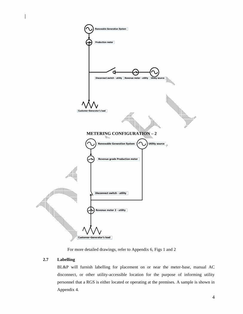
2.6 Metering
BL&P will furnish metering to measure separately the energy supplied from BL&P’s
Grid and the energy supplied to BL&P’s Grid by the customer whose RGS has been
approved by BL&P (“Customer-Generator”). Customer-Generators must also make
provision for measurement of the total energy produced by the RGS. This may be done
by having additional metering installed by BL&P at the Customer-Generator’s expense or
by the Customer-Generator installing equipment suitable for this purpose, subject to
BL&P’s approval. All metering locations must be readily accessible to BL&P personnel.
The two metering configurations are as follows:
METERING CONFIGURATION – 1
4
METERING CONFIGURATION – 2
For more detailed drawings, refer to Appendix 6, Figs 1 and 2
2.7 Labelling
BL&P will furnish labelling for placement on or near the meter-base, manual AC
disconnect, or other utility-accessible location for the purpose of informing utility
personnel that a RGS is either located or operating at the premises. A sample is shown in
Appendix 4.
5
2.8 Insurance
It is the Customer-Generator’s sole responsibility to maintain in effect for the duration of
the Interconnection Agreement general liability insurance in the amount of not less than
ONE HUNDRED THOUSAND DOLLARS ($100,000.00) for RGS up to 5kW, or not
less than FIVE HUNDRED THOUSAND DOLLARS ($500,000.00) for RGS greater
than 5kW. An endorsement on a homeowner’s policy providing the required amount of
coverage is acceptable to meet this insurance requirement. The Customer-Generator is
required to submit a copy of a valid insurance certificate for the RGS. The failure of the
Customer-Generator to renew the insurance coverage will render the Interconnection
Agreement and the Power Purchase Agreement null and void. BL&P does not accept
responsibility for the failure of the Customer-Generator to renew its insurance policy.
2.9 Liability
The Customer shall hold harmless and indemnify BL&P for all loss to third parties
resulting from the operation of the RGS, except when the loss occurs due to negligent
actions of BL&P. BL&P shall hold harmless and indemnify the Customer-Generator for
all loss to third parties resulting from the operation of BL&P’s Grid, except when the loss
occurs due to negligent actions of the Customer-Generator.
2.10 Future Modifications and Expansion
Prior to modifying, expanding or altering the RGS, the Customer-Generator must obtain
written permission from GEED to alter or extend an existing installation. Thereafter, the
Customer-Generator must seek prior written approval from BL&P before interconnecting
the modified RGS to BLP’s Grid.
2.11 Renewable Capacity on BL&P Grid
For the overall safety and protection of BL&P’s Grid, the interconnection of all RGS for
the pilot is limited to 1% of BL&P’s system’s peak demand. Any additional
interconnections above this limit are at the sole discretion of BL&P.
2.12 Customer-owned equipment protection
It is the Customer-Generator’s sole responsibility to protect its facility loads and
generation equipment and comply with the requirements of all appropriate and relevant
standards, codes and local authorities. Please see Appendix 3.
6
2.13 Additional fees
Customer-Generators may be required to pay BL&P additional fees for services related to
the installation of the RGS. Additional costs payable by the Customer-Generator to
BL&P above and beyond the Application fee, if any, will be cost-based and applied as
appropriate. For example, the Customer-Generator may undertake, at its expense, to have
BL&P install the production meters required for interconnection.
3.0 BL&P OPERATING CONDITIONS
This section describes typical BL&P distribution operating and power quality conditions within
which the RGS must operate. These are representative values that BL&P attempts to maintain and
includes some abnormal conditions that the RGS should be designed to withstand. It is the
Customer-Generator’s responsibility to ensure that all equipment operates correctly in this
environment.
3.1 System Frequency
BL&P’s Grid operates at 50 Hz. Frequency deviations typically range from 49.8 to 50.2
Hz for small contingencies resulting in modest disturbances where the RGS is expected
to remain connected to BL&P’s Grid. For larger contingencies, broader frequency
variations may occur such as when major generation or transmission is lost and load
shedding occurs. The RGS’s required response in these situations is specified in Table 2.
3.2 System Voltage
BL&P supplies secondary voltages as stated in the booklet “Information and
Requirements Covering Installation of Electric Services and Meters” dated September
2005, or the latest revision thereof. A voltage tolerance of +/_ 6 % is applicable to allow
for varying load conditions as shown in Table 1. Contingencies may arise that cause the
voltage to deviate outside of this tolerance and the RGS must be capable of operating
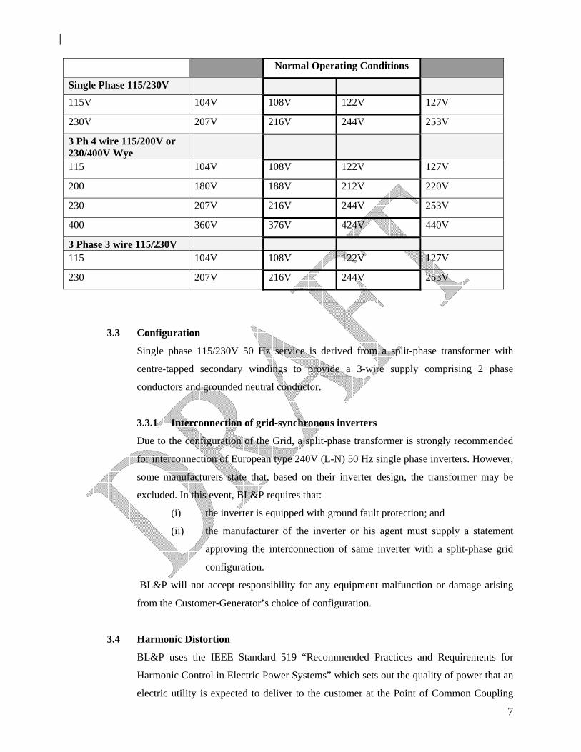
satisfactorily within the extreme voltage level variation limits shown in Table 1.
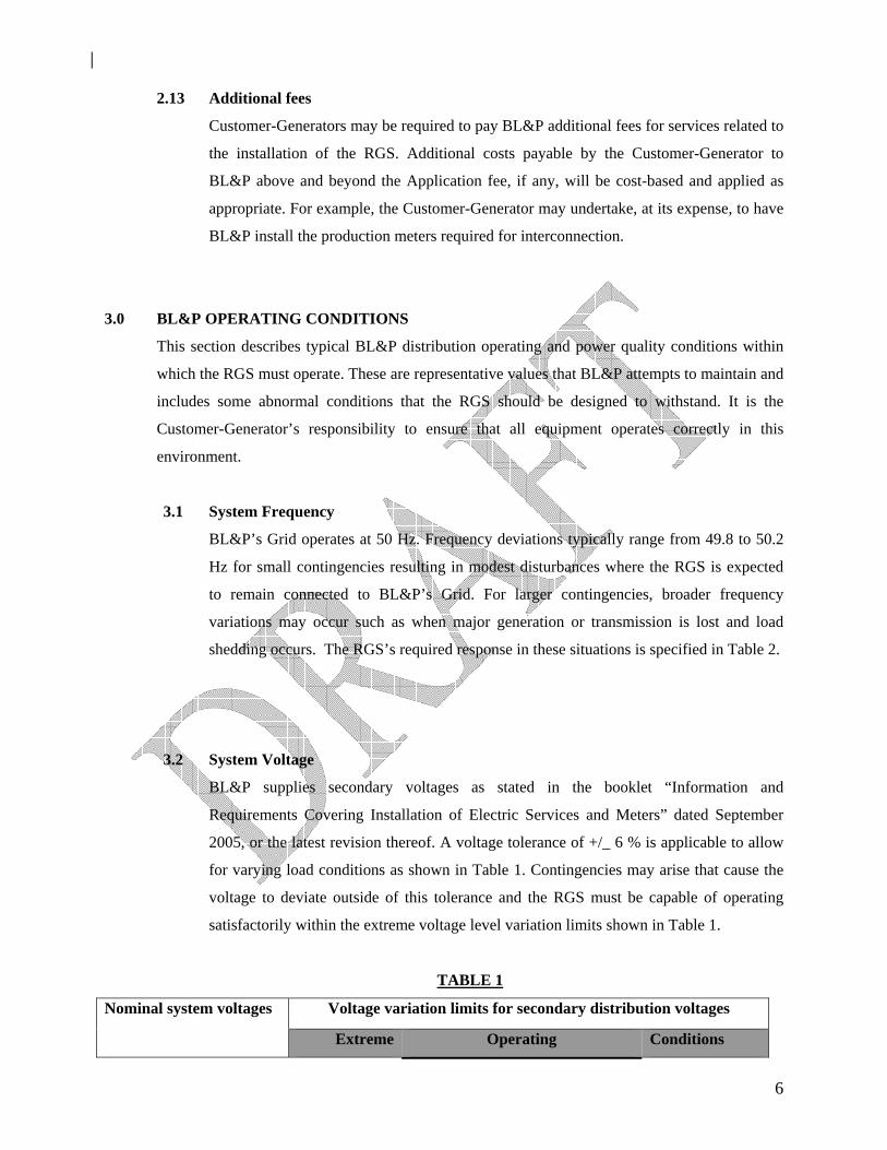
TABLE 1
Nominal system voltages Voltage variation limits for secondary distribution voltages
Extreme Operating Conditions
7
Normal Operating Conditions
Single Phase 115/230V
115V 104V 108V 122V 127V
230V 207V 216V 244V 253V
3 Ph 4 wire 115/200V or 230/400V Wye
115 104V 108V 122V 127V
200 180V 188V 212V 220V
230 207V 216V 244V 253V
400 360V 376V 424V 440V
3 Phase 3 wire 115/230V 115 104V 108V 122V 127V
230 207V 216V 244V 253V
3.3 Configuration
Single phase 115/230V 50 Hz service is derived from a split-phase transformer with
centre-tapped secondary windings to provide a 3-wire supply comprising 2 phase
conductors and grounded neutral conductor.
3.3.1 Interconnection of grid-synchronous inverters
Due to the configuration of the Grid, a split-phase transformer is strongly recommended
for interconnection of European type 240V (L-N) 50 Hz single phase inverters. However,
some manufacturers state that, based on their inverter design, the transformer may be
excluded. In this event, BL&P requires that:
(i) the inverter is equipped with ground fault protection; and
(ii) the manufacturer of the inverter or his agent must supply a statement
approving the interconnection of same inverter with a split-phase grid
configuration.
BL&P will not accept responsibility for any equipment malfunction or damage arising
from the Customer-Generator’s choice of configuration.
3.4 Harmonic Distortion
BL&P uses the IEEE Standard 519 “Recommended Practices and Requirements for
Harmonic Control in Electric Power Systems” which sets out the quality of power that an
electric utility is expected to deliver to the customer at the Point of Common Coupling
8
(“PCC”) and describes the voltage and current waveforms that exist throughout the
BL&P’s Grid. Transient conditions exceeding the limits may be encountered. IEEE
Standard 519 Section 11.5 recommends that the voltage distortion limits, as a percentage
of the nominal fundamental frequency voltage in the utility service, should not exceed
5% for the total voltage harmonic distortion and 3% for any individual harmonic.
3.5 Voltage Imbalance
The voltage imbalance on BL&P’s Grid under normal operating conditions is typically
under 3% but may reach 6%. This imbalance is included in the voltage variation shown in
Table 1. Voltage imbalance is calculated using RMS voltage levels measured phase to
phase at the service entrance under no load conditions.
Voltage imbalance (%) = 100 x {(Maximum deviation from average voltage) ÷ (average voltage)}
3.6 Fault and Line Clearing
BL&P may use automatic reclosing to maintain the reliability of BL&P’s Grid. The
owner of the RGS needs to be aware of line reclosing when designing or purchasing
protection schemes to ensure that the RGS ceases to energize before the automatic
reclosing of BL&P substation breakers. Grid-tied inverters manufactured to the UL 1741
Standard are recommended for this purpose. Systems manufactured to other international
standards may be accepted subject to the written approval of BL&P.
4.0 TECHNICAL INTERCONNECTION REQUIREMENTS
This section provides the technical requirements to be met by the RGS in order to qualify for
interconnection to BL&P’s Grid and lists typical conditions and response to abnormal conditions
that the RGS is required to meet. Except as modified herein, the RGS must conform to IEEE
Standard 1547 – “Standard for Interconnecting Distributed Resources with Electric Power
Systems”.
4.1 Point of delivery – Responsibilities
The Point of Delivery must be identified on the renewable system single line diagram
sent with the Application. BL&P will co-ordinate the design, construction, maintenance
and operation of the facilities on BL&P side of the Point of Common Coupling The
9
Customer-Generator is responsible for the design, construction, maintenance and
operation of the facilities on the Customer-Generator side of the Point of Delivery.
4.2 Point of Disconnection – Safety
A lockable disconnecting device with visible break is required to provide a point of
isolation between the RGS and BL&P’s Grid for safe working purposes. It should be
installed by the Customer-Generator at a height not exceeding 5 ft 6 ins above grade, in a
visible and accessible location near to BL&P’s revenue meter or the Point of Delivery,
whichever is acceptable to BL&P. A sample disconnect switch is shown in Appendix 5.
4.3 Interconnection Grounding
The RGS must be grounded as per the manufacturers’ recommendations and according to
the requirements of the GEED. BL&P provides a grounded neutral service conductor.
4.4 Interrupting Device ratings
The design of the RGS must consider the fault current contributions from both generation
sources to ensure that all circuit fault interrupters are adequately sized.
4.5 Over-current Protection
The RGS must detect and promptly cease to energize for over-current fault conditions
within its system.
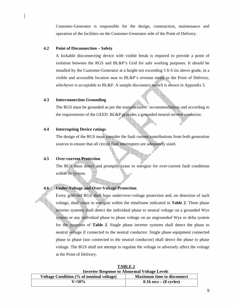
4.6 Under-Voltage and Over-Voltage Protection
Every grid-tied RGS shall have under/over-voltage protection and, on detection of such
voltage, shall cease to energize within the timeframe indicated in Table 2. Three phase
inverter systems shall detect the individual phase to neutral voltage on a grounded Wye
system or any individual phase to phase voltage on an ungrounded Wye or delta system
for the purposes of Table 2. Single phase inverter systems shall detect the phase to
neutral voltage if connected to the neutral conductor. Single phase equipment connected
phase to phase (not connected to the neutral conductor) shall detect the phase to phase
voltage. The RGS shall not attempt to regulate the voltage or adversely affect the voltage
at the Point of Delivery.
TABLE 2
Inverter Response to Abnormal Voltage Levels Voltage Condition (% of nominal voltage) Maximum time to disconnect
V<50% 0.16 secs – (8 cycles)
10
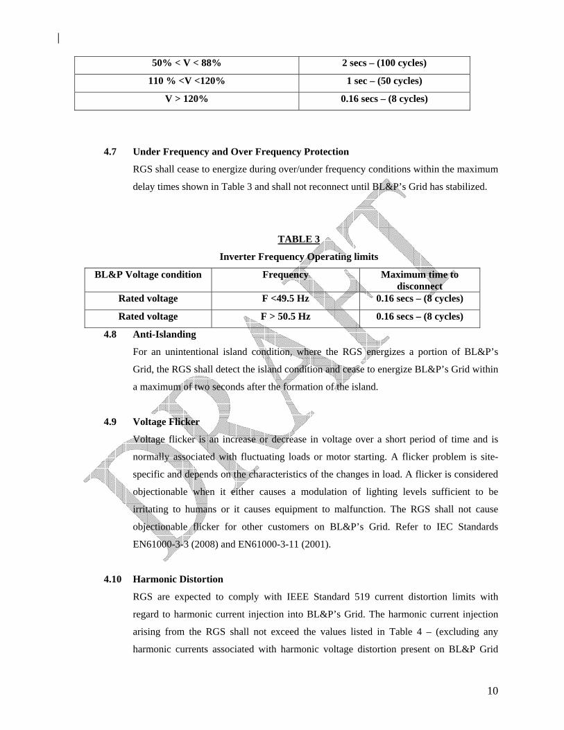
50% < V < 88% 2 secs – (100 cycles)
110 % <V <120% 1 sec – (50 cycles)
V > 120% 0.16 secs – (8 cycles)
4.7 Under Frequency and Over Frequency Protection
RGS shall cease to energize during over/under frequency conditions within the maximum
delay times shown in Table 3 and shall not reconnect until BL&P’s Grid has stabilized.
TABLE 3
Inverter Frequency Operating limits
BL&P Voltage condition Frequency Maximum time to disconnect
Rated voltage F <49.5 Hz 0.16 secs – (8 cycles)
Rated voltage F > 50.5 Hz 0.16 secs – (8 cycles)
4.8 Anti-Islanding
For an unintentional island condition, where the RGS energizes a portion of BL&P’s
Grid, the RGS shall detect the island condition and cease to energize BL&P’s Grid within
a maximum of two seconds after the formation of the island.
4.9 Voltage Flicker
Voltage flicker is an increase or decrease in voltage over a short period of time and is
normally associated with fluctuating loads or motor starting. A flicker problem is site-
specific and depends on the characteristics of the changes in load. A flicker is considered
objectionable when it either causes a modulation of lighting levels sufficient to be
irritating to humans or it causes equipment to malfunction. The RGS shall not cause
objectionable flicker for other customers on BL&P’s Grid. Refer to IEC Standards
EN61000-3-3 (2008) and EN61000-3-11 (2001).
4.10 Harmonic Distortion
RGS are expected to comply with IEEE Standard 519 current distortion limits with
regard to harmonic current injection into BL&P’s Grid. The harmonic current injection
arising from the RGS shall not exceed the values listed in Table 4 – (excluding any
harmonic currents associated with harmonic voltage distortion present on BL&P Grid
11
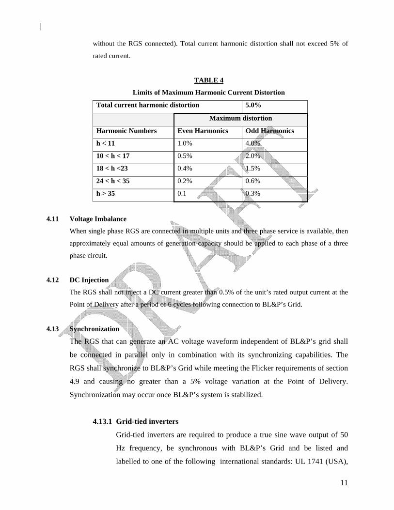
without the RGS connected). Total current harmonic distortion shall not exceed 5% of
rated current.
TABLE 4
Limits of Maximum Harmonic Current Distortion
Total current harmonic distortion 5.0%
Maximum distortion
Harmonic Numbers Even Harmonics Odd Harmonics
h < 11 1.0% 4.0%
10 < h < 17 0.5% 2.0%
18 < h <23 0.4% 1.5%
24 < h < 35 0.2% 0.6%
h > 35 0.1 0.3%
4.11 Voltage Imbalance
When single phase RGS are connected in multiple units and three phase service is available, then
approximately equal amounts of generation capacity should be applied to each phase of a three
phase circuit.
4.12 DC Injection
The RGS shall not inject a DC current greater than 0.5% of the unit’s rated output current at the
Point of Delivery after a period of 6 cycles following connection to BL&P’s Grid.
4.13 Synchronization
The RGS that can generate an AC voltage waveform independent of BL&P’s grid shall
be connected in parallel only in combination with its synchronizing capabilities. The
RGS shall synchronize to BL&P’s Grid while meeting the Flicker requirements of section
4.9 and causing no greater than a 5% voltage variation at the Point of Delivery.
Synchronization may occur once BL&P’s system is stabilized.
4.13.1 Grid-tied inverters
Grid-tied inverters are required to produce a true sine wave output of 50
Hz frequency, be synchronous with BL&P’s Grid and be listed and
labelled to one of the following international standards: UL 1741 (USA),
12
G83/1 (UK), VDE0126-1-1 (Germany), CSA C22.2 No. 107.1-01
(Canada), 4777.2 part 2 (Australia).
Systems comprising grid-tied inverters with battery backup are configured
differently and are more complex than battery-less grid-tied systems. In
the interest of safety, the designs of battery back-up grid-tied systems must
be approved by GEED & BL&P prior to installation.
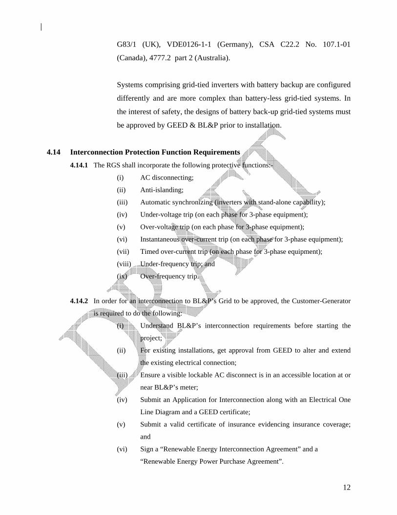
4.14 Interconnection Protection Function Requirements
4.14.1 The RGS shall incorporate the following protective functions:-
(i) AC disconnecting;
(ii) Anti-islanding;
(iii) Automatic synchronizing (inverters with stand-alone capability);
(iv) Under-voltage trip (on each phase for 3-phase equipment);
(v) Over-voltage trip (on each phase for 3-phase equipment);
(vi) Instantaneous over-current trip (on each phase for 3-phase equipment);
(vii) Timed over-current trip (on each phase for 3-phase equipment);
(viii) Under-frequency trip; and
(ix) Over-frequency trip.
4.14.2 In order for an interconnection to BL&P’s Grid to be approved, the Customer-Generator
is required to do the following:
(i) Understand BL&P’s interconnection requirements before starting the
project;
(ii) For existing installations, get approval from GEED to alter and extend
the existing electrical connection;
(iii) Ensure a visible lockable AC disconnect is in an accessible location at or
near BL&P’s meter;
(iv) Submit an Application for Interconnection along with an Electrical One
Line Diagram and a GEED certificate;
(v) Submit a valid certificate of insurance evidencing insurance coverage;
and
(vi) Sign a “Renewable Energy Interconnection Agreement” and a
“Renewable Energy Power Purchase Agreement”.
13
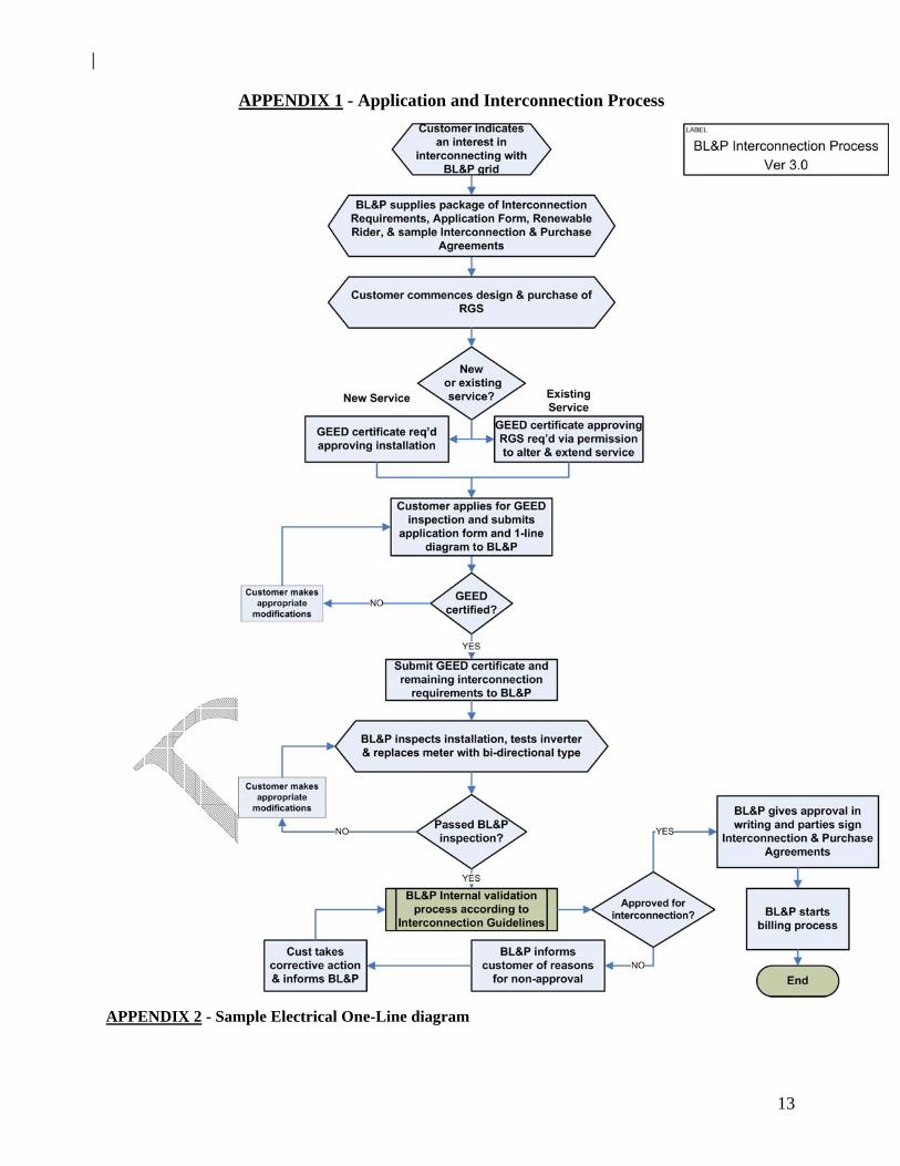
APPENDIX 1 - Application and Interconnection Process
APPENDIX 2 - Sample Electrical One-Line diagram
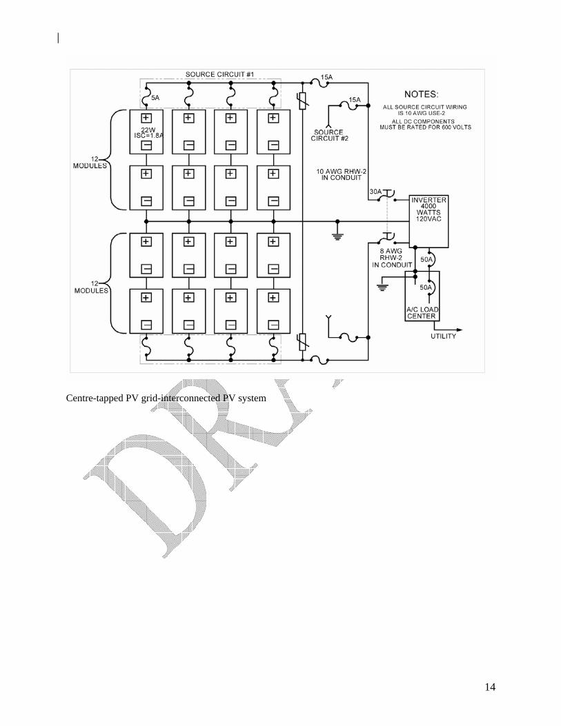
14
Centre-tapped PV grid-interconnected PV system
15
APPENDIX 3 - Summary of PV and Interconnection-Related Technical Standards
IEEE Std 928 Recommended Criteria for Terrestrial PV Power Systems IEEE Std 1547 Standard for Distributed Resources Interconnected with Electric Power
Systems – standard for technical interconnection requirements IEEE Std 519 Recommended Practices and Requirements for Harmonic Control in
Electrical Power Systems - standard for allowable harmonic waveform distortions
IEEE Std 1262 Recommended Practice for Qualification of Photovoltaic Modules IEEE Std 1374 Guide for Terrestrial Photovoltaic Power System Safety IEEE Std 1479 Recommended Practice for the Evaluation of Photovoltaic Module Energy
Production UL Std 1741 Static Inverters and Charge Controllers for use in PV Power Systems – a
testing protocol that certifies the safe operation of grid-connected inverters UL Std 1703 Flat-Plate Photovoltaic Modules and Panels NFPA 70 Article 690 (NEC Code)
Solar Photovoltaic Systems – standard for installation of PV systems
NFPA 70 Article 705 (NEC Code)
Interconnected Electric Power Production Sources – standard for installation of grid-connected systems
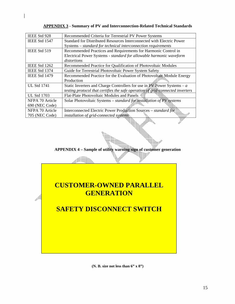
APPENDIX 4 – Sample of utility warning sign of customer generation
(N. B. size not less than 6” x 8”)
CUSTOMER-OWNED PARALLEL GENERATION
SAFETY DISCONNECT SWITCH
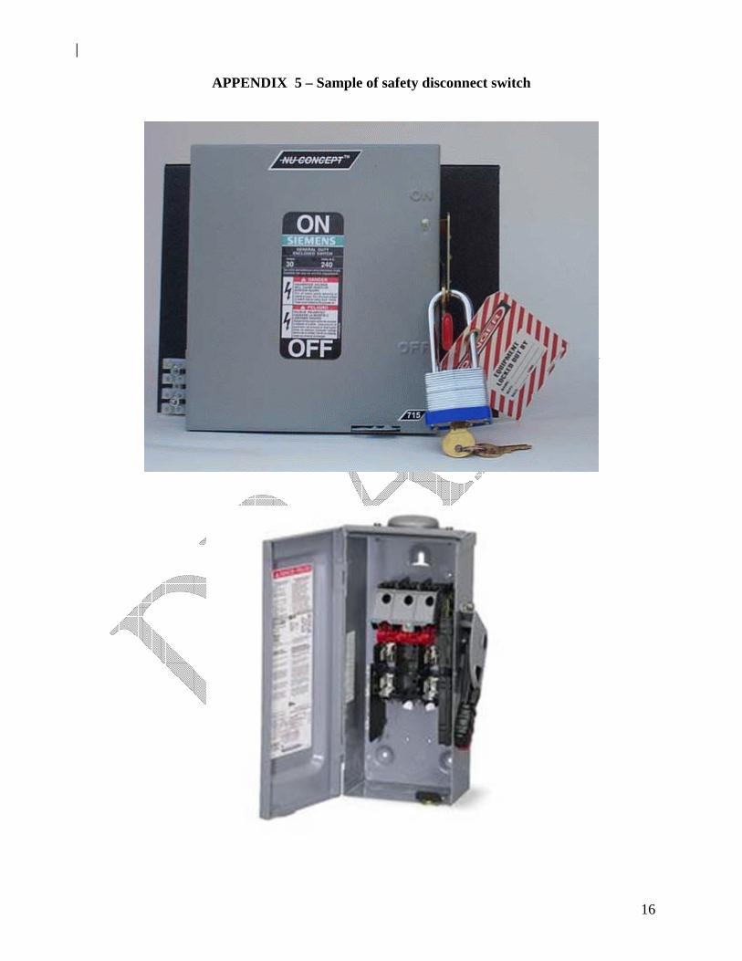
16
APPENDIX 5 – Sample of safety disconnect switch
17
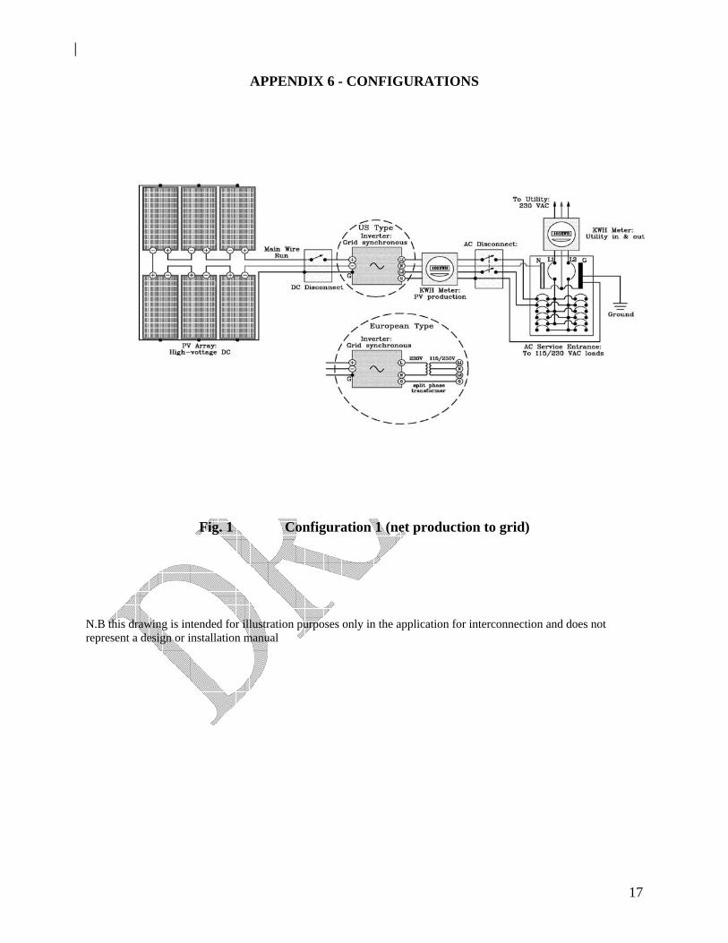
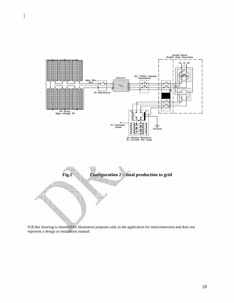
APPENDIX 6 - CONFIGURATIONS
Fig. 1 Configuration 1 (net production to grid)
N.B this drawing is intended for illustration purposes only in the application for interconnection and does not represent a design or installation manual
18
Fig.2 Configuration 2 – total production to grid N.B this drawing is intended for illustration purposes only in the application for interconnection and does not represent a design or installation manual

19
GLOSSARY
Alternating Current (AC): An electric current that reverses its direction at regularly recurring
intervals, known as the frequency which, in the case of Barbados, is 50 times per second.
Automatic Reclosing: automatic reclosing refers to the automatic restoration of power by
devices following a fault. It may involve a sequence of short interruptions before permanent
restoration or cessation of power.
Capacity (gross): The full-load continuous rating of the Renewable Generation System, under
specified conditions, as designated by the manufacturer. It is usually indicated on the nameplate
attached to the equipment.
Customer-Generator: The person or entity accepting responsibility for the electricity account
associated with the Renewable Generation System.
Delta (∆) connection: A method for connecting three phase supply where each phase is
connected in series with the next, separated by a phase rotation of 120 degrees. Compare with
wye (Y) (star) connection.
Direct Current (DC): An electric current that flows in a constant direction. The magnitude of the
current does not vary or has a very slight variation.
Distribution System: The local poles, wires, transformers, substations and other equipment
used to deliver electricity to consumers. (See grid also)
Flicker: Flicker (voltage) is an unsteady visual sensation associated with changing lighting
luminance caused by sudden and repetitive increases or decreases in voltage over a short
period of time. It is normally associated with fluctuating loads or motor starting.
Frequency Protection (over/under): Use of relays or other devices to protect lines or
equipment by causing circuits to open based on the degree by which the measured frequency
varies from a set value.
Generation (Electricity): The process of producing electric energy from other forms of energy;
also, the amount of electric energy produced, expressed in watthours (Wh).

20
Grid : A network for the transmission of electricity throughout a region. The term is also used to
refer to the layout of an electric distribution system Grounding: An electrical connection to the earth or a body that extends from an earth
connection for the purposes of safety and voltage reference. Harmonics: Distortions in the sinusoidal voltage and current waveforms caused by the
overlapping of the fundamental waveform at 50 Hz with other waveforms of integral multiple
frequencies of the fundamental waveform. Total harmonic distortion (THD) is summation of all
the distortions at the various harmonic frequencies.
Hybrid System: A self-generation system that combines multiple power sources (such as solar
and wind) and is located behind a single electric utility service meter. Energy storage systems
such as batteries do not constitute a power source for this purpose of the definition.
Interconnection Agreement: A legal document authorizing the flow of electricity between the
facilities of two electric systems. Renewable energy systems must be permanently
interconnected and operating in parallel to the electrical distribution grid of the utility serving the
customer’s electrical load.
Interrupting Device Rating: The highest current that a device is intended to safely interrupt at
rated voltage.
Inverter: A device that converts dc electricity into ac electricity. Some types are used for stand-
alone systems (not connected to the grid) and others are designed as utility-interactive
systems to operate in parallel with the utility to supply common loads and may deliver
power to the utility.
Islanding: Islanding is a condition which occurs when an interconnected Renewable
Generation System continues to energize the facility (and the grid) after a utility power
interruption. Industry practice requires that the Renewable Generation System be disconnected
promptly according to applicable standards to avoid equipment damage and safety hazards to
personnel.

21
Overcurrent Protection: Use of a device or relay to protect the system by tripping it offline
based on the degree by which the measured current varies from a set value.
The trip may be instantaneous or after a preset time.
Kilowatt (kW): A measure of instantaneous power equal to one thousand watts of electricity
(See Watt).
Kilowatthour (kWh): A quantity of electricity usage measured by your electric meter equal to
one thousand watthours.
Manual Disconnect switch: A manual switch required for interconnection to disconnect the renewable generation source from the utility line.
Net Metering: Arrangement that permits a facility to offset its electrical consumption against
energy delivered by the grid at the retail value and sell power in excess of its local consumption.
Net billing: Arrangement that permits the utility (using two meters or one meter that separately
measures inflows and outflows of electricity) to sell power delivered to the customer at the
prevailing tariff, and buy excess power from the customer’s RGS at a rate contracted by the
utility. The utility issues a net bill for each billing period.
Peak Watt: A manufacturer's unit indicating the amount of power a photovoltaic cell or module
will produce at standard test conditions (normally 1,000 watts per square meter and 25 degrees
Celsius).
Photovoltaic (PV) Cell: An electronic device consisting of layers of semiconductor materials
fabricated to form a junction (adjacent layers of materials with different electronic
characteristics) and electrical contacts and being capable of converting incident light directly into
electricity (direct current)
Photovoltaic (PV) Module: An integrated assembly of interconnected photovoltaic cells
designed to deliver a selected level of working voltage and current at its output terminals,
packaged for protection against environment degradation, and suited for incorporation in
photovoltaic power systems

22
Point of Common Coupling: The point where the electrical conductors of the utility’s
distribution system are connected to the customer’s conductors and where any transfer of
electric power between the customer and the distribution system takes place.
Point of Delivery: The point where the Renewable Generation System is electrically connected
to the electric utility for metering purposes.
Point of Disconnection: The point at an accessible location where the disconnect switch used
to isolate the Renewable Generation System from the utility is located.
Renewable Energy: Energy flows that occur naturally and repeatedly in the environment (such
as solar, wind, biomass) and can be harnessed for human benefit.
Renewable Generation System: The total components and subsystems that, in combination,
convert renewable energy into electrical energy suitable for connection to utilisation loads.
Root Mean Square (RMS): Used for AC voltage and current, this quantity equals the square
root of the average of the squares of all the instantaneous values occurring during one cycle. It
is considered as the effective value of AC because, for a fixed resistive load, the AC rms voltage
will produce the same heating effect as a DC voltage of equivalent value.
. Solar Energy: The radiant energy of the sun, which can be converted into other forms of
energy, such as heat or electricity Sunlight can be converted to electricity directly, as in the case
of photovoltaic (PV) applications or indirectly as in the case of solar thermal applications
Synchronization: The process of connecting two previously separated ac sources such as the
customer’s private generation system and the utility’s grid, to allow them to operate in parallel
(after matching frequency, voltage, phase angles etc.)
Total Harmonic Distortion (voltage and current): This is a single number representation of
the amount of distortion of a voltage or current electrical waveform from a true sine wave.
Voltage protection (over/under): Use of relays or other devices to protect lines or equipment
by causing circuits to open based on the degree by which the measured voltage varies from a
set value.

23
Voltage (current) Waveform: The variation of voltage (current) over one cycle indicated by the
pattern which results when the instantaneous value of voltage (current) is plotted with respect to
time over a cycle. Ideally, AC waveforms are represented by sinusoids and DC waveforms are
constant over time.
Watt (Electric): The electrical unit of power. The rate of energy transfer equivalent to 1 ampere
of electric current flowing under a pressure of 1 volt at unity power factor
Watthour (Wh): The electrical energy unit of measure equal to 1 watt of power supplied to, or
taken from, an electric circuit steadily for 1 hour.
Wind energy: Energy present in wind motion that can be converted to mechanical energy for
driving pumps, mills, and electric power generators.
Wye (Y, star) Connection: A method for connecting three phase supply where each individual
conductor is connected to a common point, which may be grounded or ungrounded. Compare
with delta (∆) connection.