Embed Size (px)
Citation preview

BMCLaboratory Fume Hoods
Represented By:
BMCP.O. Box 4089Muskegon MI 49444Telephone: (231) 733-1206FAX: (231) 733-2116e-mail: [email protected] page: www.bmclab.com
© BMC 2006
M E M B E R
SEFASCIENTIFIC
EQUIPMENT &
FURNITURE
ASSOCIATION
Cover 1/27/06, 11:12 AM1

Airfoil
ADA Fume Hoods.............................................................12
ADA Fume Hood Assemblies............................................13
Add Air Fume Hoods........................................................10
Add Air Fume Hood Assemblies........................................11
Bypass Fume Hoods........................................................... 6
Bypass Fume Hood Assemblies......................................... 7
Low Bench Fume Hoods....................................................18
Low Bench Fume Hood Assemblies.................................19
Perchloric Acid Fume Hoods............................................16
Perchloric Acid Fume Hood Assemblies...........................17
Radio Isotope Fume Hoods................................................14
Radio Isotope Fume Hood Assemblies..............................15
Variable Volume Fume Hoods........................................... 8
Variable Volume Fume Hood Assemblies........................... 9
Walk-In Fume Hoods.........................................................18
Walk-In Fume Hood Assemblies........................................19
Alarms...................................................................................28
Anemometer..............................................................................32
Baffle Options.........................................................................31
Base Cabinets.........................................................................26
Baths.......................................................................................30
Blowers..............................................................................33-34
Canopy Hoods.........................................................................26
Ceiling Enclosures..................................................................27
Countertops.............................................................................29
Definitions.............................................................................38
1
Demonstration Fume Hood....................................................22
Drains....................................................................................30
Electrical Fixtures...................................................................29
Filler Panels............................................................................26
Filters.....................................................................................32
Fire Extinguishers..................................................................31
Flow Patterns......................................................................... 3
Introduction........................................................................... 2
Lattice Assemblies.................................................................32
Local Exhaust.........................................................................33
Material Options.....................................................................31
Planning................................................................................. 4
Plumbing Rough-In................................................................35
Portable Fume Hood...............................................................23
Sash Options..........................................................................27
Service Fixtures.......................................................................28
Sinks......................................................................................30
Smoke....................................................................................32
Specifications..........................................................................36
Spray Booth.......................................................................24-25
Thin Wall Fume Hood............................................................20
Thin Wall Fume Hood Assemblies........................................21
Transitions..............................................................................33
Traps........................................................................................30
Vent Kits..................................................................................31
Wash Down............................................................................33
Y Branches.............................................................................33
Table of Contents BMC/Laboratory Fume HoodsBMC/Laboratory Fume Hoods
NOTES:
40
inside 1-11 1/26/06, 11:32 AM1
Introduction
you with maximum safety at minimum cost.Incorporating standard options, such as combinationsashes and sash stops, allows you to maintain facevelocities while exhausting less air. Hence, the BMC FumeHood costs less to operate than other conventional units.
REFERENCES – The American Industrial HygieneAssociation, The American Conferences of GovernmentalIndustrial Hygienists and the American Society ofHeating, Refrigerating and Air-Conditioning Engineershave all published guidelines on Fume Hood facevelocities and operating procedures.
Because the performance of a Fume Hood is greatlyaffected by the surrounding conditions, the recommendationsin this catalog are based on normal or averageconditions. For recommendations on ideal or extremeconditions, the guidelines published by the abovereferenced agencies should be followed.
SPECIFICATIONS – BMC Fume Hoods are manufacturedin strict accordance with the specifications shown in thiscatalog. However, continuous testing and research mayresult in design and specification changes withoutadvance notice.
BMC/Laboratory Fume Hoods
2
GENERAL – The name BMC has long been synonymouswith quality and longevity. Our newly redesigned FumeHood is a proud example of this reputation. Over 50 yearsof experience, combined with state-of-the-artengineering and testing facilities, provide you with aFume Hood unsurpassed in quality and performance.
TESTING – Safety should be the number one concernwhen choosing a Fume Hood. That is why BMC testsand certifies each style Fume Hood in accordance withthe current ASHRAE method of testing performance oflaboratory Fume Hoods.
The ASHRAE 110 test procedure is an industrystandard, recognized by SEFA and the AmericanConference of Governmental Industrial Hygienists, forsafe Fume Hood performance.
Our test facility is available for you to witness theASHRAE test procedure or to test special designs. Tomake arrangements to visit our test facility, contact yourlocal BMC Representative or our Main Office inMuskegon, MI.
DESIGN – The design of the BMC Fume Hood provides
BMC/Laboratory Fume Hoods
NOTES:
39
inside 1-11 1/26/06, 11:32 AM2

Flow Patterns
Airfoil Bypass Hoods
The Airfoil Bypass Hoods have a double bypass to provideconstant exhaust volume and limit changes in face velocity.
The upper bypass functions automatically with the raising andlowering of the sash. The lower bypass provides a continuousair sweep of the work surface.
When hood top enclosures are used, a bypass grille must bespecified.
Airfoil Variable Air Volume Hoods
The Variable Air Volume (VAV) Hoods are designed to be usedwith exhaust control systems provided by other manufacturers.
In lieu of an upper bypass the VAV Hood has a lintel whichrestricts the air intake of the Hood to the sash opening and lowerbypass.
The commercially available exhaust control system will detectthe movement of the sash and adjust the volume of air requiredto maintain a constant face velocity.
Factory mounting of the exhaust controls is available whenspecified.
Airfoil Add Air Hoods
The Add Air Hoods provide up to 70% of the Hood exhaustrequirements. With a bypass similar to the Airfoil Bypass Hood,outside air is introduced through the add air plenum, thusminimizing the amount of conditioned room air required.
When outside temperatures are extreme, it may be necessary totemper the incoming air.
BMC/Laboratory Fume Hoods
Sash Closed Sash Open
Sash Closed Sash Open
3
Sash Closed Sash Open
BMC/Laboratory Fume HoodsDefinitions
Exhaust Collar – Connection between exhaust duct andFume Hood through which all exhaust air passes.
Face Velocity – Speed of air moving into Fume Hoodentrance or access opening, expressed in feet per minute(FPM).
Liner - Interior lining used for side, back, top enclosurepanels, exhaust plenum and baffle system of a laboratoryFume Hood.
Lintel - Portion of laboratory Fume Hood front locateddirectly above the access opening.
Resin-Chem - White chemical resistant fiberglassreinforced thermoset resin sheet.
Sash - Movable transparent panel set in Fume Hoodentrance.
Service Fitting - Fixture laboratory plumbing mounted onthe Fume Hood intended to control the supply of piped gasesand liquids for laboratory use.
Static Pressure - Air pressure in laboratory Fume Hood orduct, usually expressed in inches of water.
Static Pressure Loss - Measurement of resistance createdwhen air moves through a duct or hood, usually expressedin inches of water.
Superstructure - That portion of a laboratory Fume Hoodthat is supported by the countertop.
Add Air - Supply air delivered to a laboratory Fume Hoodto reduce room air consumption..
Air Foil – Curved or angular members at the Fume Hoodentrance.
Air Volume – Quanity of air normally expressed in cubicfeet per minute (CFM).
ASHRAE - American Society of Heating, Refrigerating andAir Conditioning Engineers.
Baffle - Panel located across the Fume Hood interior backwhich controls the pattern of air moving into and throughthe Fume Hood.
Blower - Air moving device, sometimes called a fan,consisting of a motor, impeller and housing.
Bypass - Compensating opening that maintains a relativelyconstant volume exhaust through a Fume Hood regardlessof sash position and that functions to limit the maximumface velocity as the sash is lowered.
Canopy Hood - Suspended ventilating device for non-critical use to exhaust only heat, water vapor and odors.
Countertop - Work surface resting on a base cabinet.
Duct - Round, square or rectangular tube used to enclosemoving air.
Duct Velocity - Speed of air moving in a duct, usuallyexpressed in feet per minute (FPM).
38
inside 1-11 1/26/06, 11:32 AM3

Figure 2 Poor Locations
The presence of cross-drafts will adversely affect theperformance or the Fume Hood. For this reason it is a good ideanot to locate the Fume Hood near open doors andwindows. High velocity air diffusers located directly in front ofthe Fume Hood could actually draw fumes out of the Hood andinto the room. Although there is no single preferred method fordelivery of make up air, it is a good idea to locate the Fume Hoodas far from the air diffuser as possible so that the air first sweepsthrough the laboratory working area and then into the Fume Hood.
Fume Hood Velocity SelectionSelection of the Fume Hood face velocity should be directly re-lated to the location of the Fume Hood. A Fume Hood in a goodlocation, as shown in Fig. 1, should operate properly at a facevelocity of 75 FPM. A poorly located Fume Hood, as shown inFig. 2, may require a face velocity of 125 FPM to maintain properperformance.
Since most fume hood installations require some type oflocation compromise, a face velocity of 100 FPM isusually the norm. Fume Hoods with a high heat source may re-quire slightly higher face velocities.
OSHA calls for, but does not require, a face velocity of 150 FPMfor Fume Hoods used with any of the 13 carcinogens listed inOSHA 1910.1003 et seq. (OSHA 1978). Studies have shown thathoods operated at face velocities of 150 FPM and greater oftenperform poorer than if operated at a lower face velocity, due todisruptive air turbulence at the perimeter of the Hood openingand in the wake of objects placed inside the work area of the Hood.
Fume Hood Blowers & DuctworkThe blower and ductwork control the amount of air moving throughthe Fume Hood. For this reason it is extremely important that theybe installed and maintained properly.
By using the chart on page 34, you can choose the correct blowerfor the Fume Hood you have selected.
Lineof
Traffic
Lineof
Traffic
Air ConditioningRegister
Hood
Center Table
Hood Base Cabinets
Base Cabinets
Sealed Windows
BMC/Laboratory Fume HoodsPlanning
Figure 1 Good Locations
Fume Hood SelectionThere are two main factors to consider when selecting a FumeHood style.
First consider the type of work being performed in the Hood. Theuse of perchloric acid or radioactive materials require a Fume Hoodspecifically designed for these materials. Large apparatus orcomplex set-ups may require the use of a low bench or walk-inFume Hood to accommodate the space requirements.
The second consideration in selecting a Fume Hood style is theair consumption of the hood. Operation of a Fume Hoodrequires a relatively large volume of room air.
If you determine that the amount of air being supplied to the roomis adequate to accommodate the exhaust volume of the Fume Hoodthe ByPass style Fume Hood would be an excellent choice.
If there is not enough supply air available, the Add Air style maybe the right choice.
The Variable Air Volume style Fume Hood is designed to be usedwith an adjustable damper system in the ductwork. The use of thisHood will, when used in conjunction with a VAV control system,drastically reduce the total amount of air consumed. This makesthe Variable Air Volume style Hood a good choice when trying toreduce air consumption for energy cost savings or when theresimply is not enough available supply air.
For more information see “Flow Patterns” on Page 3.
Fume Hood LocationsLocation of the Fume Hood is of prime importance, since a varietyof conditions will affect the performance of the Hood.
When selecting a location for the Fume Hood, operatorconvenience, work flow and exhaust duct locations should all beconsidered. In addition, an attempt should be made to keep thehood away from the line of traffic. It is both inconvenient anddangerous to install a Fume Hood so that the operator is forced towork in the line of traffic movement.
Lineof
Traffic
Lineof
TrafficAir ConditioningRegisters
HoodHood
CenterTable
CenterTable
Base Cabinets
Sealed Windows
4
BMC/Laboratory Fume HoodsSpecifications
Airfoil Bypass Fume HoodsConstructed as specified above. The Airfoil Bypass FumeHood superstructure has a white Resin-Chem interior lin-ing.
Airfoil Add Air Fume Hoods
The Add Air superstructure shall have an 18 gage, paintedsteel add air plenum. The plenum shall be capable of prop-erly distributing up to 70% of the air requirements of theHood. The add air plenum shall be of standard size and canbe added to any of the standard BMC Fume Hoods.
The interior lining of the Airfoil Add Air Fume Hood su-perstructure shall be white Resin-Chem.
Airfoil Radio Isotope Hoods
The interior lining and work surface of the Radio Isotopesuperstructure shall be type 304 stainless steel. Seams andjoints present in the interior and work surface shall bewelded to eliminate pockets, cracks and crevices that wouldpermit a buildup of radioactive materials.
The work surface shall be an integral welded part of thesuperstructure. It shall be watertight and furnished with araised edge to contain spills. It shall be properly reinforcedto support 200 lbs. per square foot up to a total weight of1,000 lbs. per Hood or base cabinet section.
An 18 gage type 304 stainless steel frame shall encase thelaminated safety glass sash. The vertical sliding sash shallride in type 304 stainless steel sash guides.
Interior removable access panels are provided for access tothe interior housing.
All other features of the Hood are as specified under "Con-struction."
Airfoil Perchloric Acid Fume Hoods
Perchloric Acid Fume Hood superstructures shall beidentified by a label indicating suitability for use withperchloric acid procedures. All exposed parts of thesuperstructure interior shall be seamless welded covedcornered, type 316, stainless steel.
The work surface shall an integral welded part of thesuperstructure. It shall be watertight and furnished with araised edge to contain spills. A full width drain through shallbe located below the baffle.
A water spray (wash down system) shall be provided forrinsing the area behind the baffle. Service fitting controlsfor the wash down system shall be external to the Hood,clearly identified and within easy reach.
An 18 gage, type 316 stainless steel frame shall encase thelaminated safety glass sash. The vertical sliding sash shallride in type 316, stainless steel sash guides.
Interior removable access panels are not provided onPerchloric Acid superstructures.
All other features of the Hood are as specified under"Construction."
Low Bench Hoods
Low Bench Fume Hood superstructures shall have a whiteResin-Chem interior lining. The sash shall consist of fourhorizontal sliding, laminated safety glass panels, with astainless steel edge trim. The panels shall ride on two tracksof extruded aluminum.
Two removable interior panels shall be located on each sideof the Fume Hood superstructure.
All other fixtures of the Low Bench Fume Hoodsuperstructure are specified under "Construction."
Walk-In Fume Hoods
Walk-In Fume Hood superstructures shall have awhite Resin-Chem interior lining. The sash shall consist oftwo vertical sliding, laminated safety glass panels as specifiedunder "Construction."
Two removable interior access panels shall be located oneach side of the Fume Hood superstructure.
All other features of the Walk-In Fume Hoodsuperstructure are as specified under "Construction."
37
inside 1-11 1/26/06, 11:32 AM4

Figure 3 Figure 4 Figure 5
Planning BMC/Laboratory Fume Hoods
Whenever possible exhaust blowers should be located on the roofof the building. This will insure that the ductwork inside thebuilding will remain under negative pressure preventing leakageof contaminated air into occupied spaces.
Supply or add-air blowers may be located on the rooftop, sideledge, warehouse space or any other suitable location. The primeconcerns when locating the add-air blower is that it remain farenough away from other exhaust outlets to avoid cross-contamination. The other consideration is the temperature ofthe incoming air. Locating the add-air blower in an area ofsemi-conditioned air, like a warehouse, may provide a morecomfortable work area at the front of the Hood, while avoidingthe need to condition the supply air.
Add-Air Fume Hoods require the use of both an exhaust blowerand a supply blower. It is recommended that both blowers beconnected to a single on/off switch. This will avoid the possibilityof room contamination by turning on only the supply blower.
When using high concentrations of aerosols, solvents or otherflammable vapors inside the fume hood, an exhaust blower with anon-sparking wheel and explosion-proof motor may have to be used.
The duct material should be resistant to the materials used in theFume Hood. PVC, coated steel and stainless steel are all commonchoices. The ductwork should be installed with as few bends aspossible and have air tight joints.
Ducts are excellent conductors of sound. Anchoring the ductworksecurely to the building structure and sizing the ductwork so asnot to exceed velocities in excess of 2000 FPM will help toreduce duct noise.
The exhaust discharge should be located at least 10' above theroof structure and have a zero pressure weather cap. Coveredweather caps that increase static pressure and interfere with theflow of discharged air are not recommended.
As a rule, each Fume Hood should be exhausted by its ownexhaust blower, as shown in Figure 3. When multiple Hoods aremanifolded to a single exhaust blower, as shown infigure 4, imbalance in the exhaust airflow can occur as Hoods areturned on and off. To overcome this situation, all Hoods could be
turned on and off together. However, this may result in anunsatisfactory arrangement from the standpoint of energy efficiency.
Multiple Hoods which are controlled by a variable airvolume (VAV) control system may be manifolded to a singleexhaust blower. The VAV controls maintain the proper air balanceand provide excellent energy efficiency, by reducing the amountof air being exhausted when the Hood is not in use.
Care should be taken in the design of the VAV system. The airbeing supplied to the laboratory must also be variable to meet thechanging exhaust volume of the Fume Hoods. If not, overpressurization of the laboratory could occur causing contamina-tion of adjacent areas.
Because the exhaust volume of the VAV system can vary greatly,it is a good idea to select an exhaust blower with some type of airbypass, as shown in Figure 5. This will keep the fan motor fromoverloading and maintain an acceptable stack velocity.
Fume Hood blowers and ductwork systems should be included inthe maintenance schedule. Dust and other contaminants collectedon the blades of the fan can greatly reduce its capacity. Blowersshould be placed so that they are accessible for periodic cleaning.Periodic examination of the ductwork should also be made to de-tect any loose joints or porosity due to corrosion.
Fume Hood OperationA fume hood must be properly installed and operated in order toachieve optimum performance.
When using a Fume Hood, keep all apparatus at least 6" backfrom the face of the Hood. Do not put your head in the Hoodwhen contaminants are being generated. Do not store chemicalsor apparatus in the hood. Following these guidelines will helpinsure proper performance of the Fume Hood.
OSHA requires laboratories, where hazardous chemicals are used,to develop and carry out a written chemical hygiene plan. Thisplan should include provisions for monitoring fume hoods forproper performance, as well as periodic performance testing ofthe Fume Hoods. The Fume Hood air flow monitors, anemometerand smoke bombs shown on page 28 and 32 will help you meetthe requirements.
BMC/Laboratory Fume Hoods
heavy or light fumes. All baffles are removable forcleaning.
Unless specified for use in a variable air volume (VAV)system, the superstructures shall be provided with an airbypass feature. The bypass, located at the upper frontinterior of the Hood, shall open as the sash is lowered,providing for a relatively constant exhaust volume of theFume Hood superstructure
When specified, the upper front exterior panel of the super-structure can be furnished with louvers. The louversprovide for proper operation of the bypass feature when thetop of the superstructure is closed off to the ceiling.
A two tube, rapid start, vapor sealed fluorescent lightfixture of maximum length shall be provided on eachsuperstructure. Each fixture shall include two soft whitefluorescent tubes. Light fixtures are relamped from the topfront of the superstructure.
Exhaust outlets shall be rectangular, 18 gage stainless steel.Hoods with stainless steel interior liners shall have 18 gagestainless steel exhaust collars welded in place.
Fume Hoods shall have a full view, vertical rising,laminated safety glass sash framed with a solid black PVCedging. The sash shall have a full width finger lift with a 16gage internal support tube. The sash shall not require theuse of a center mullion. Sash guides shall be extruded, blackPVC.
The sash shall be counterbalanced with a single weightlocated in the center rear of the superstructure. Two 1/8"diameter stainless steel cables connect the sash to the weight.The use of two cables acts as a safety mechanism keeping thesash from falling in the event that one cable would fall. Thecables ride on 2" diameter nylon ball bearing pulleys. The cable/pulley assembly shall have an adjustment located on thetop of the superstructure for proper alignment of the sash.
A lower airfoil of 14 gage steel, coated with a black baked-on chemical resistant finish, shall act as the sash stop. Inaddition, the airfoil shall provide a 1" space between thebottom of the sash, in the closed position, and the worksurface. This 1" space shall provide for a continuous sweepof fumes from the work surface.
BMC Fume Hood Specifications
GeneralBMC Fume Hoods shall be of a “picture frame” air foildesign and construction. Each Fume Hood superstructureshall provide for safe efficient removal of all fumes, bothheavy and light, with the least amount of turbulence as theair enters the Hood.
Standard airfoil bench Hood superstructures are tested inaccordance with the current ASHRAE Test Procedureand perform well within the American Conference ofGovernmental Industrial Hygienists recommendations.
Material
Metal: Prime furniture steel, free of scales, buckles, or otherdefects; ASTM A366.
Stainless Steel: Type 304 or 316, as noted, commercialgrade. No. 4 Finish, ASTM A167.
Safety Glass: 7/32" Laminated; conforming to ANSI Z97.1for 400-foot-pound impact, and to CPSC 16 CFR 1201 forCategory II Safety Glazing.
PVC: Extruded Black PVC.
Resin-Chem: White chemical resistant, fiberglass reinforcedthermoset resin sheet.
ConstructionFume Hood superstructures have a double wallconstruction consisting of an outer shell of sheet steel andan inner liner of corrosion resistant material as specified.Attachment of the interior lining material to the steelframing members is made with non-metallic fasteners. Thedouble wall shall house and conceal steel framingmembers, attaching brackets and remote operating servicefixture valves.
The exterior side panels of the superstructure are constructedof 18 gage steel and are removable for access into theinterior housing. Access may also be gained throughremovable panels in the interior liner.
Each superstructure shall have an internal baffle system ofthe same material as the interior liner. This baffle systemshall provide for safe efficient removal of fumes when thesuperstructure is connected to a properly installed exhaustsystem. A manual adjustment is provided on the upper partof the baffle to allow the operator to set the Fume Hood for
Specifications
36 5
inside 1-11 1/26/06, 11:32 AM5

356
Interior LightingA maximum width, two tube fluorescent light fixture,complete with tubes, is provided with the Airfoil BypassFume Hood. The light fixture is mounted above a sealedsafety glass panel isolating it from corrosive fumes andhazardous vapors. Tube lights are easily replaced throughthe top front of the Fume Hood superstructure.
OptionsA variety of optional service fixtures are available fromBMC for installation in the Bypass Fume Hood. Our BMCrepresentatives work closely with customers in specifyingthe type of fixtures and electrical receptacles required.
B-608 96"
BMC/Laboratory Fume Hoods
Fume Hood Superstructures are available in widths from 48" to 96", including BMC's unique 84" wide model as shown below. Serviceand electrical fixtures shown are optional and must be ordered separately.
Airfoil BypassFume Hoods
Continuous air flow across the work surface of the AirfoilBypass Fume Hood exhausts potentially hazardous vaporssafely away from the work environment, even with the sashclosed!
The Airfoil Bypass Fume Hood features an internalbypass opening located above the sash allowing for aconstant exhaust volume while maintaining the facevelocity. In operation, the bypass works automatically, inconjunction with the hood sash. The bypass adjustment ismade as the sash is opened and closed creating a relativelyconstant face velocity regardless of sash position.
Design
The Bypass Fume Hood comes equipped with a full viewsash providing an unobstructed view of the Hood interiorwork area. The sash, a glazed 7/32" thick laminated safetyglass is provided with a full width flush pull. Acounterweight provides for one finger operation of the sashat any position.
The entrance of the Hood is framed with inward-angledmembers. This angled frame works to minimize turbulenceand provide smooth movement of air into the Hood,resulting in a more efficient operation of the Fume Hood atface velocities ranging from 60 to 150 FPM. A lowerairfoil sash stop maintains a 1" space (below closed sash)that allows air to flow continuously across the worksurface inside the Hood.
Double wall construction of the Hood superstructure allowsfor easy installation of service fixtures and routing ofinterior plumbing and electrical lines. The interior of theAirfoil Bypass Fume Hood is white “Resin-Chem.”Removable access panels on both interior sides of the Hoodare standard features. The exterior superstructure sidepanels are also removable for easy access to servicefixtures and supply lines.
B-604 48" B-605 60" B-606 72" B-607 84"
The above illustration depicts the routing of service andelectrical lines in a typical Fume Hood. Unless specifiedothrewise, all service and electrical fixtures are shippedseparately for installation in the field. Piping, conduit andwire are not included and must be furnished by others inaccordance with local codes.
Light Switch
Vac.
Vac.
Air
Air
Gas
Gas
C.W.
Duplex Electrical Outlet
Flourescent Light
Rectangular Duct Collar
Removable Access Panel
Cupsink
P-Trap
Waste Line
Supply Lines
Conduit
Shut-Off Valves
Junction Box
BMC/Laboratory Fume HoodsPlumbing Rough-in
Fluorescent Light
The exact routing of service lines will vary depending onthe point of origin and number of services. The illustrationshown above shows the service lines feeding up throughthe Hood from the floor. Service lines can also be routedthrough the Fume Hood side wall from the ceiling.
inside 1-11 1/26/06, 11:32 AM6

Airfoil BypassAssemblies
Airfoil Bypass Fume Hood AssembliesThe five standard Fume Hood sizes are each available as acomplete assembly.
Detailed information on base cabinets, countertops andservice fixtures is shown on pages 26, 28 and 29.
The assembly for the 48" and 60" wide Hoods consists of astandard base cabinet, two LF35-7 filler panels, dished
Rough-in Details
Duct collar locations are as shown above. The center line of each collar is 8" from theback of the hood. The area indicated by the dashed lines is designated for plumbing andelectrical rough-ins. All rough-ins should be kept within 7" of the wall and 18" from thefloor.
B-9040 48" B-9050 60"
54 1
/4"
31"
22"
48"
8"
7" 1"
30"
33 1/2"
66 5
/8"
35 3
/4"
2 3/
8"
90"
35"
89 1
/4"
BMC/Laboratory Fume Hoods
The static pressures listed above are for the hoods only. An appropriate amount willhave to be added to this figure to compensate for the pressure drop through the ductsystem. The total pressure drop through the hood and the duct system must be known toselect the proper exhaust blower.
epoxy resin countertop, F-400 3" x 6" epoxy resin cupsink, sixF-100 service fixtures, F-110 cold water fixture, F-200 lightswitch, F-210 blower switch and two F-220 110V duplexes.
72", 84" and 96" assemblies include all of the above alongwith a second base cabinet, cupsink and water fixture.
All service and electrical fixtures are furnished, but notinstalled.
B-9060 72" B-9070 84" B-9080 96"
33 7/8"
HOODSIZE
48"
60"
72"
84"
96"
COLLARSIZE
6" x 12"
6" x 16"
6" x 20"
(2)6" x 12"
(2)6" x 12"
75 FPM 100 FPM 125 FPM 150 FPM
CFM
650
850
1050
1250
1450
CFM
867
1133
1400
1667
1933
CFM
1083
1417
1750
2083
2417
CFM
1300
1700
2100
2500
2900
S.P.
.22
.21
.21
.21
.25
S.P.
.39
.38
.37
.37
.45
S.P.
.61
.59
.58
.58
.71
S.P.
.87
.85
.84
.83
1.02
35"
22 1/2"
23 1/2"
22 1/2" 25 1/2" 25 1/2"
29"24" 30" 36"
23 1/2" 23 1/2" 26 1/2" 26 1/2"
B-604 B-605 B-606
B-607 B-608
BMC/Laboratory Fume Hoods
VELOCITYFPM
100100100100100
100SUPPLY
100SUPPLY
100SUPPLY
100SUPPLY
100SUPPLY
100100100100100
125125125125125
150150150150150
100100
100100
100100100100100
100100
505050
HOODMODEL NO.
B-604B-605B-606B-607B-608
B-624
B-625
B-626
B-627
B-628
B-684B-685B-686B-687B-688
B-634B-635B-636B-637B-638
B-644B-645B-646B-647B-648
B-656B-658
B-666B-668
B-834B-835B-836B-837B-838
B-814B-816
B-7730B-7740B-7760
AIRFOIL BYPASS FUME HOODS
AIRFOIL ADD AIR FUME HOODS
AIRFOIL ADA FUME HOODS
AIRFOIL RADIO ISOTOPE AIR FUME HOODS
AIRFOIL PERCHLORIC ACID FUME HOODS
AIRFOIL LOW BENCH FUME HOODS
AIRFOIL WALK-IN FUME HOODS
THIN WALL FUME HOODS
DEMONSTRATION FUME HOODS
CANOPY FUME HOODS
VOLUMECFM
8671133140016671933
867607
1133793
1400980
1667116719331353
433567700833967
10831417175020832417
13001700210025002900
11071529
15752175
9471206146417221981
758992
96311381502
DUCTDIA
9"10"12"12"14"
9"9"
10"10"12"12"12"12"14"14"
9"10"12"12"14"
9"10"12"12"14"
9"10"12"12"14"
10"12"
12"14"
9"10"12"12"14"
10"10"
12"12"12"
0-25 L/F OF DUCTBLOWER
9B11C12C12D15D
9B9A11C11A12C12A12E12B15D13C
8A8A9A11A9C
9D11E12E13F15E
GFE-12DGFE-12DGFE-12FGFE-15HGFE-15H
11C12D
12C15D
9C11D12D12E15D
11A11C
12A12B12D
RPM
1016882686725565
1016813882693686545747580565575
95011268266741064
12961155848821671
22002570272822592431
880700
705570
10781033836809570
750870
479580705
25-50 L/F OF DUCTBLOWER
9B11D12D12D15D
9B9A11D11A12D12A12E12B15D13C
8A8A9A11A9C
9D11E12E13F15E
GFE-12DGFE-12EGFE-12FGFE-15HGFE-15I
11D12D
12D12D
9C11D12E12E15D
11A11C
12A12B12D
RPM
1144981733747565
1144880981750733560788625565596
98511268266741064
13491195886876703
22002570288623962557
979769
740614
10781076877888611
764870
501625750
50-75 L/F OF DUCTRPM
12031026822788603
12038971026757822608868650603640
102011268266741064
14491267823933766
23822732288625222557
1020851
794649
10781117895886645
791870
523650836
75-100 L/F OF DUCT
BlowersBlowers
FAN SIZE9
11121315
GFE-12*GFE-15*
INLET9" DIA. OD10" DIA.OD
13 1/4" DIA. OD14 1/2" DIA. OD16 1/8" DIA. OD12 1/2" DIA. ID**15 1/2" DIA. ID**
OUTLET10 3/4" X 6 1/2" O.D.
11 3/4 X 8" O.D.13 1/4" X 9 5/8" O.D.
14 5/8" X 10 3/4" O.D.16 1/4" X 11 3/4" O.D.
13 1/2" X 18 1/8"O.D.**15 1/2" X 21 1/4" O.D.**
*=PVC Construction **=Flanged Connection
ELEC. REQUIREMENTSABCDEFGHI
VOLTAGE115/230, 1PH115/230, 1PH115/230, 1PH115/230, 1PH
200/208/460, 3PH200/208/460, 3PH200/208/460, 3PH200/208/460, 3PH200/208/460, 3PH
HORSEPOWER1/61/41/31/23/41
1 1/41 3/4
2
BLOWER
9D11D12D12D15D
9D9A11D11A12D12A12E12B15D13C
8A8A9A11A9C
9E11E12E13F15F
GFE-12EGFE-12FGFE-12GGFE-15IGFE-15I
11D12E
12D15E
9C11E12E12F15E
11A11C
12A12B12D
BLOWER
9C11D12D12D15D
9C9A11D11A12D12A12E12B15D13C
8A8A9A11A9C
9D11E12E13F15F
GFE-12DGFE-12FGFE-12FGFE-15IGFE-15I
11D12D
12D15E
9C11E12E12F15E
11A11C
12A12B12D
RPM
12811071865829603
12619741071822865668906677603685
105511268267461064
15431337923990766
23822732288626372600
1068900
877680
10781150915923652
822870
545677877
34 7
inside 1-11 1/26/06, 11:32 AM7
Airfoil VariableVolume Fume Hoods
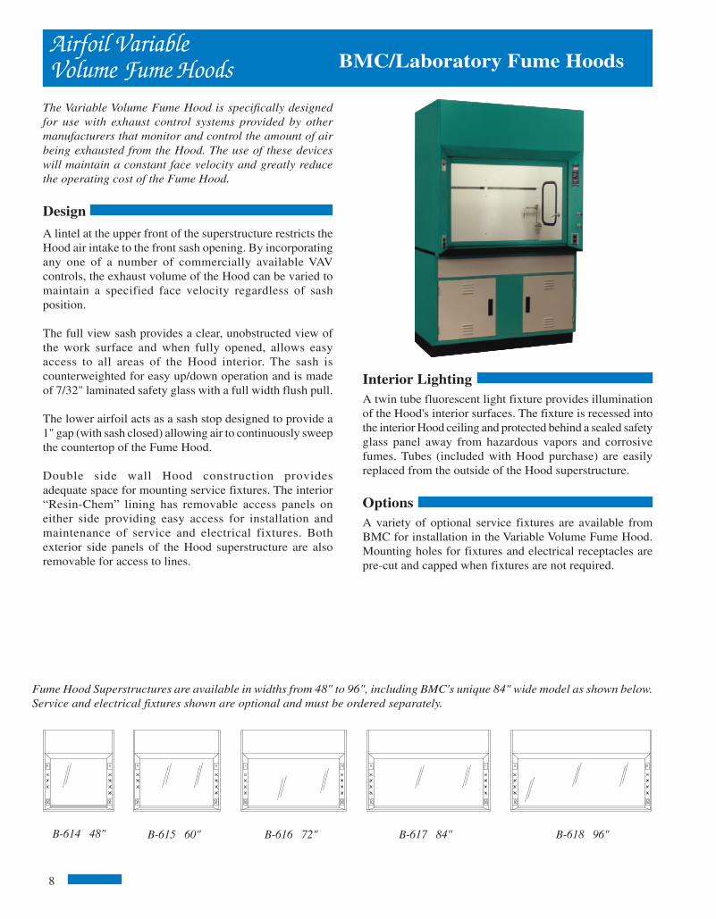
Interior LightingA twin tube fluorescent light fixture provides illuminationof the Hood's interior surfaces. The fixture is recessed intothe interior Hood ceiling and protected behind a sealed safetyglass panel away from hazardous vapors and corrosivefumes. Tubes (included with Hood purchase) are easilyreplaced from the outside of the Hood superstructure.
OptionsA variety of optional service fixtures are available fromBMC for installation in the Variable Volume Fume Hood.Mounting holes for fixtures and electrical receptacles arepre-cut and capped when fixtures are not required.
Fume Hood Superstructures are available in widths from 48" to 96", including BMC's unique 84" wide model as shown below.Service and electrical fixtures shown are optional and must be ordered separately.
B-618 96"B-617 84"
BMC/Laboratory Fume Hoods
The Variable Volume Fume Hood is specifically designedfor use with exhaust control systems provided by othermanufacturers that monitor and control the amount of airbeing exhausted from the Hood. The use of these deviceswill maintain a constant face velocity and greatly reducethe operating cost of the Fume Hood.
Design
A lintel at the upper front of the superstructure restricts theHood air intake to the front sash opening. By incorporatingany one of a number of commercially available VAVcontrols, the exhaust volume of the Hood can be varied tomaintain a specified face velocity regardless of sashposition.
The full view sash provides a clear, unobstructed view ofthe work surface and when fully opened, allows easyaccess to all areas of the Hood interior. The sash iscounterweighted for easy up/down operation and is madeof 7/32" laminated safety glass with a full width flush pull.
The lower airfoil acts as a sash stop designed to provide a1" gap (with sash closed) allowing air to continuously sweepthe countertop of the Fume Hood.
Double side wall Hood construction providesadequate space for mounting service fixtures. The interior“Resin-Chem” lining has removable access panels oneither side providing easy access for installation andmaintenance of service and electrical fixtures. Bothexterior side panels of the Hood superstructure are alsoremovable for access to lines.
B-614 48" B-615 60" B-616 72"
8
BMC/Laboratory Fume HoodsAccessories
Duct Transitions
Duct Transitions are designed to convert the rectangular collorof the BMC Fume Hood to a round collar.
Transitions are constructed of heavy gage coated steel and willwork with standard round ductwork.
F-500 6"x12" Collar to 9" Dia.F-501 6"x12" Collar to 10" Dia.F-502 6"x14" Collar to 9" Dia.F-503 6"x16" Collar to 10" Dia.F-504 6"x20" Collar to 12" Dia.
Y Branches
Transitions
Y-Branches
Duct Wash Down
F-508 Wash Down assemblies are suited for use withperchloric acid duct systems. Each nozzle is capable ofdelivering 3 gallons of water per minute at a water pressure of40 PSI. The Wash Down assembly is designed to be attachedto 12" dia. duct and has a 1/4" male pipe connection.
F-508
BlowersBlowers for both exhaust and supply are designed for efficient, quiet, continuous duty.Units have a forward curved impeller and come complete with a weatherproof drive cover.Spark resistant and corrosion resistant coatings are available upon request.
When using the chart on page 34, figure the equivalent of 15 linear feet of ductwork foreach 90 degree elbow. For complex exhaust systems, contact your BMC representativefor assistance in selecting a blower.
Local Exhaust
F-509
F-509 The BMC Local Exhaust Hood is designed for use withatomic absorption spectrophotometers or flamephotometer equipment. Unit comes complete with a 12" dia.stainless steel cone, 8' of 6" dia. flexible duct and adjustablesupport arm.
33
Y Branches are used to connect two exhaust or supply ducts onFume Hoods that require more than one exhaust or supplycollar. Branches are constructed of coated steel and will workwith standard round ductwork.F-506 (2) 9" Dia. to a Single 12" Dia.F-507 (2) 9" Dia. to a Single 14" Dia.
inside 1-11 1/26/06, 11:44 AM8

Airfoil VariableVolume Assemblies
Airfoil Variable Volume AssembliesThe five standard Fume Hood sizes are each available as acomplete assembly.
Detailed information on base cabinets, countertops andservice fixtures is shown on pages 26, 28 and 29.
The assembly for the 48" and 60" wide Hoods consists of astandard base cabinet, two LF35-7 filler panels, dished
Rough-in Details
B-9140 48" B-9150 60" B-9180 96"
54 1
/4"
31"
22"
48"
8"
7" 1"
30"
33 1/2"
66 5
/8"
35 3
/4"
2 3/
8"
90"
89 1
/4"
35"
33 7/8"
BMC/Laboratory Fume Hoods
epoxy resin countertop, F-400 3" x 6" epoxy resin cupsink, sixF-100 service fixtures, F-110 cold water fixture, F-200 lightswitch, F-210 blower switch and two F-220 110V duplexes.
72", 84" and 96" assemblies include all of the above alongwith a second base cabinet, cupsink and water fixture.
All service and electrical fixtures are furnished, but notinstalled.
B-9160 72" B-9170 84"
HOODSIZE
48"
60"
72"
84"
96"
COLLARSIZE
6" x 12"
6" x 16"
6" x 20"
(2)6" x 12"
(2)6" x 12"
75 FPM 100 FPM 125 FPM 150 FPM
CFM
650
850
1050
1250
1450
CFM
867
1133
1400
1667
1933
CFM
1083
1417
1750
2083
2417
CFM
1300
1700
2100
2500
2900
S.P.
.22
.21
.21
.21
.25
S.P.
.39
.38
.37
.37
.45
S.P.
.61
.59
.58
.58
.71
S.P.
.87
.85
.84
.83
1.02
The static pressures listed above are for the hoods only. An appropriate amount willhave to be added to this figure to compensate for the pressure drop through the ductsystem. The total pressure drop through the hood and the duct system must beknown to select the proper exhaust blower.
Duct collar locations are as shown above. The center line of each collar is 8" fromthe back of the hood. The area indicated by the dashed lines is designated forplumbing and electrical rough-ins. All rough-ins should be kept within 7" of the walland 18" from the floor.
35"
22 1/2"
23 1/2"
22 1/2" 25 1/2" 25 1/2"
29"24" 30" 36"
23 1/2" 23 1/2" 26 1/2" 26 1/2"
B-614 B-615 B-616
B-617 B-618
9
BMC/Laboratory Fume Hoods
F-445
F-446
F-441
F-423F-424
F-422
F-417
F-416
Accessories
Lattice Assemblies
Lattice assemblies consist of the components listed below andcan be configured as required. Lattice rods come in standardlength and can be cut in the field for an exact fit.
F-441 36" x 1/2" DIA. RODF-442 48" x 1/2" DIA. RODF-443 72" x 1/2" DIA. RODF-444 96" x 1/2" DIA. RODF-445 CLAMP FOR 1/2" DIA. RODF-446 FOOT FOR 1/2" DIA. ROD
F-422 Hand held, rotating vane anemometer is ideal formonitoring Fume Hood face velocity. The unit which iscompletely self-contained is powered by a 9-volt battery and canbe operated with one hand.
Operation is simple, with a single push-button control in thehandle. When the button is depressed and held the unit willdisplay a digital read-out of the Fume Hood face velocity.
Smoke
A variety of smoke generating devices are available to monitorthe airflow into and around the Fume Hood.
F-415 Smoke sticks generate 2-3 minutes of continuous smokeand come in packages of 12.
F-416 Smoke bottle contains an ampule that, when broken,releases a dense white smoke.
F-417 Smoke cartridges generate 45 seconds of continuoussmoke and come in packages of 10.
Filters
F-415
Anemometer
Exhaust filters are used to entrap and retain airborne particles of contaminationat their source of origin, preventing the spread of contamination through the ductworkand through the point of discharge.Note: not recommended for use with radioisotopes
Filter housing assemblies consist of a stainless steel enclosure with a removable facepanel that permits installation of the pre-filter and HEPA filter.
F-423 Filter housing measures 25 13/16" x 23 7/8" x 24 3/8" and includes a 24" x 24"x 11 1/2" HEPA filter and pre-filter. Collar size is 10" Diameter.
F-424 Filter housing measures 31 13/16" x 30 3/8" x 24 3/8" and includes a 24" x 30"x 11 1/2" HEPA filter and pre-filter. Collar size is 12" Diameter.32
inside 1-11 1/26/06, 11:33 AM9
Fume Hood Superstructures are available in widths from 48" to 96", including BMC's unique 84" wide model as shown below. Service andelectrical fixtures shown are optional and must be ordered separately.
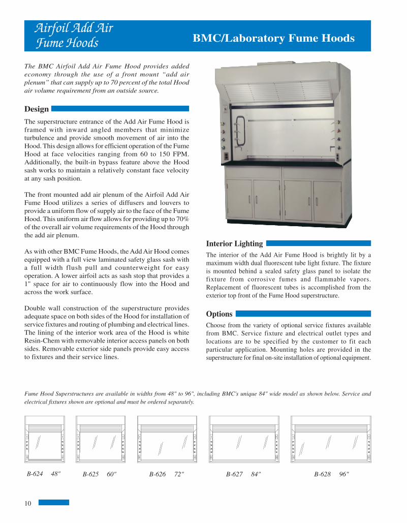
Interior LightingThe interior of the Add Air Fume Hood is brightly lit by amaximum width dual fluorescent tube light fixture. The fixtureis mounted behind a sealed safety glass panel to isolate thefixture from corrosive fumes and flammable vapors.Replacement of fluorescent tubes is accomplished from theexterior top front of the Fume Hood superstructure.
OptionsChoose from the variety of optional service fixtures availablefrom BMC. Service fixture and electrical outlet types andlocations are to be specified by the customer to fit eachparticular application. Mounting holes are provided in thesuperstructure for final on-site installation of optional equipment.
B-628 96"
BMC/Laboratory Fume HoodsAirfoil Add AirFume Hoods
The BMC Airfoil Add Air Fume Hood provides addedeconomy through the use of a front mount “add airplenum” that can supply up to 70 percent of the total Hoodair volume requirement from an outside source.
Design
The superstructure entrance of the Add Air Fume Hood isframed with inward angled members that minimizeturbulence and provide smooth movement of air into theHood. This design allows for efficient operation of the FumeHood at face velocities ranging from 60 to 150 FPM.Additionally, the built-in bypass feature above the Hoodsash works to maintain a relatively constant face velocityat any sash position.
The front mounted add air plenum of the Airfoil Add AirFume Hood utilizes a series of diffusers and louvers toprovide a uniform flow of supply air to the face of the FumeHood. This uniform air flow allows for providing up to 70%of the overall air volume requirements of the Hood throughthe add air plenum.
As with other BMC Fume Hoods, the Add Air Hood comesequipped with a full view laminated safety glass sash witha full width flush pull and counterweight for easyoperation. A lower airfoil acts as sash stop that provides a1" space for air to continuously flow into the Hood andacross the work surface.
Double wall construction of the superstructure providesadequate space on both sides of the Hood for installation ofservice fixtures and routing of plumbing and electrical lines.The lining of the interior work area of the Hood is whiteResin-Chem with removable interior access panels on bothsides. Removable exterior side panels provide easy accessto fixtures and their service lines.
B-624 48" B-625 60"
10
B-626 72" B-627 84"
BMC/Laboratory Fume HoodsAccessoriesand Options
Vent Kits
F-440 Vent Kits are used to vent acid or flammable storagecabinets to the Fume Hood.
F-439
Material Options
The design of the BMC Fume Hoods allows for easysubstitution of standard components with optionalmaterials.
Interior linings are available in minerit, PVC or stainlesssteel in lieu of our standard Resin-Chem.
Sash options include full framed, painted or stainless steelsash.
Sash tracks and lower airfoils are both available instainless steel.
Contact your BMC representative to assist you inspecifying these items.
Baffle Options
Standard Fume Hoods are equipped with an adjustable upperbaffle only. Other adjustable baffle options are availableas follows:
B-790 Lower Adjustable BaffleB-791 Single Point Remote Adjustable Baffle for 48", 60" and 72" HoodsB-792 Single Point Remote Adjustable Baffle for 84" and 96" Hoods
F-440
31
Fire Extinguishers
F-439 Automatic Fire Extinguisher units are available for in-stallation in Fume Hoods. Fire Extinguishers are activated by afusible link. The link melts at 165º F, opening the valve whichreleased a multipurpose ABC Dry Chemical. Cylinders are con-structed of stainless steel and come complete with mountingbracket. Fume Hoods 72" and wider require the use of two FireExtinguishers for adequate projection.
inside 1-11 1/26/06, 11:33 AM10

Airfoil Add AirAssemblies
Airfoil Add Air Hood AssembliesThe five standard Fume Hood sizes are each available as acomplete assembly.
Detailed information on base cabinets, countertops andservice fixtures is shown on pages 26, 28 and 29.
The assembly for the 48" and 60" wide Hoods consists of astandard base cabinet, two LF35-7 filler panels, dished
Rough-in Details
The static pressures listed above are for the hoods only. An appropriate amount will haveto be added to this figure to compensate for the pressure drop through the duct system.The total pressure drop through the hood and the duct system must be known to select theproper exhaust blower. Supply figures are based on 70% add air.
35"
22 1/2"
23 1/2"
22 1/2" 25 1/2" 25 1/2"
29"
Duct collar locations are as shown above. The center line of each collar is 8" from the backof the hood. The center line of the supply duct is 35 5/8" from the back of the hood. Thearea indicated by the dashed lines is designated for plumbing and electrical rough-ins. Allrough-ins should be kept within 7" of the wall and 18" from the floor.
54 1
/4"
31"
22"
48"
8"
7" 1"
30"
35 1/4"
40 1/2"
66 5
/8"
35 3
/4"
2 3/
8"
90" 24"
B-624 B-625 B-626
36"
23 1/2" 23 1/2"
B-627 B-628
26 1/2"26 1/2"
30"
35"
89 1
/4"
35 5/8"
40 7/8"
B-9280 96"B-9240 48"
COLLARSIZE
6" x 12"6" x 12"6" x 16"6" x 16"6" x 20"6" x 20"
(2)6" x 12"(2)6" x 12"(2)6" x 12"(2)6" x 14"
75 FPM 100 FPM 125 FPM 150 FPM
CFM650455850595
1050735
1250875
14501015
S.P..22.17.21.17.21.17.21.15.25.17
CFM867607
1133793
1400980
1667116719331353
CFM1083758
1417992
175012252083145824171691
CFM1300910
17001190210014702500175029002030
S.P..39.30.38.29.37.31.37.29.45.31
S.P..61.48.59.47.58.46.58.46.71.49
S.P..87.69.85.69.84.68.83.71
1.02.71
EXHSUPEXHSUPEXHSUPEXHSUPEXHSUP
HOODSIZE
48"
60"
72"
84"
96"
11
B-9270 84"B-9260 72"B-9250 60"
epoxy resin countertop, F-400 3" x 6" epoxy resin cupsink, sixF-100 service fixtures, F-110 cold water fixture, F-200 lightswitch, F-210 blower switch and two F-220 110V duplexes.
72", 84" and 96" assemblies include all of the above alongwith a second base cabinet, cupsink and water fixture.
All service and electrical fixtures are furnished, but notinstalled.
BMC/Laboratory Fume HoodsBMC/Laboratory Fume Hoods
F-425
Baths
F-420
Sinks, Drainsand Baths
Sinks
Sinks are available in a variety of sizes and configurations forinstallation in Fume Hoods.
F-400 - Oval epoxy resin cupsink, 3"x6", 1 1/2" NPT outletconnection.
F-401 - Oval polypropyene panel mount cupsink, 3"x6", withretainer nut, 1 1/2" NPT outlet connection.
F-402 - Rectangular epoxy resin cupsink, 13 3/4" x 4 1/2"x 5 1/2" with stainless steel straining screen, 1 1/2" NPT outlet.
F-410 - Drop-in epoxy resin sink, 16" x 12" x 8" Dp.
F-411 - Drop-in epoxy resin sink, 18" x 15" x 8" Dp.
F-412 - Drop-in epoxy resin sink, 24" x 16" x 8" Dp.
Baths
Baths are available in steam, hot water or electric. Each bathis furnished with four sets of concentric rings which are spacedon 1" increments up to 6" diameter. Baths are constructed of 20gauge, type 304 stainless steel and come complete with aremote valve for mounting in the post of the Fume Hood. Size is18" x 18".
F-430 SteamF-431 Hot WaterF-432 Electric
Drains and Traps
F-420 - Epoxy resin sink outlet with retainer nut, 1 1/2" NPToutlet connection.
F-425 - Polypropylene p-trap with adjustable riser, 1 1/2" NPToutlet connection.
F-400
F-402
F-410F-411F-412
30
inside 1-11 1/26/06, 11:33 AM11
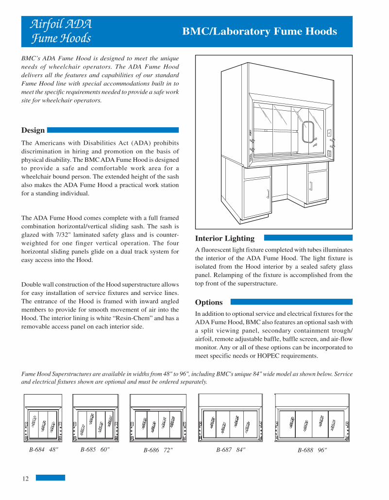
Interior LightingA fluorescent light fixture completed with tubes illuminatesthe interior of the ADA Fume Hood. The light fixture isisolated from the Hood interior by a sealed safety glasspanel. Relamping of the fixture is accomplished from thetop front of the superstructure.
OptionsIn addition to optional service and electrical fixtures for theADA Fume Hood, BMC also features an optional sash witha split viewing panel, secondary containment trough/airfoil, remote adjustable baffle, baffle screen, and air-flowmonitor. Any or all of these options can be incorporated tomeet specific needs or HOPEC requirements.
BMC/Laboratory Fume HoodsAirfoil ADAFume Hoods
BMC’s ADA Fume Hood is designed to meet the uniqueneeds of wheelchair operators. The ADA Fume Hooddelivers all the features and capabilities of our standardFume Hood line with special accommodations built in tomeet the specific requirements needed to provide a safe worksite for wheelchair operators.
Design
The Americans with Disabilities Act (ADA) prohibitsdiscrimination in hiring and promotion on the basis ofphysical disability. The BMC ADA Fume Hood is designedto provide a safe and comfortable work area for awheelchair bound person. The extended height of the sashalso makes the ADA Fume Hood a practical work stationfor a standing individual.
The ADA Fume Hood comes complete with a full framedcombination horizontal/vertical sliding sash. The sash isglazed with 7/32" laminated safety glass and is counter-weighted for one finger vertical operation. The fourhorizontal sliding panels glide on a dual track system foreasy access into the Hood.
Double wall construction of the Hood superstructure allowsfor easy installation of service fixtures and service lines.The entrance of the Hood is framed with inward angledmembers to provide for smooth movement of air into theHood. The interior lining is white “Resin-Chem” and has aremovable access panel on each interior side.
B-684 48" B-685 60" B-686 72" B-688 96"B-687 84"
Fume Hood Superstructures are available in widths from 48" to 96", including BMC's unique 84" wide model as shown below. Serviceand electrical fixtures shown are optional and must be ordered separately.
12
BMC/Laboratory Fume HoodsElectrical Fixturesand Countertops
Electrical Services
Flush mount electrical service fixtures come complete with devicebox and stainless steel face plate.
Explosion proof fixtures meet Class 1, Group C & D requirements.Explosion proof outlets and switches must be mounted on the frontpanel of the base cabinet or the exterior side of the Fume Hood.
For factory setting of electrical fixtures, specify part number F-340in addition to the electrical fixture number.
For factory setting and wiring of electrical fixtures, specify partnumber F320 in addition to the electrical fixturenumber.
Factory wiring of explosion proof fixtures on application only.
F-200 - Single pole light switch, 115 volt, 15 amp.
F-210 - Manual motor starter switch with pilot light, 115 volt, 15amp. Heating element not included.
F-220 - Duplex receptacle, 115 volt, 15 amp.
F-221 - Duplex receptacle, 115 volt, 20 amp.
F-225 - GFI duplex receptacle, 115 volt, 15 amp.
F-260 - Explosion proof light fixture, specify two fixtures on hoods84" and over.
F-262 - Explosion proof receptacle.
F-264 - Explosion proof switch.
Countertops
B-8040 48"B-8050 60"B-8060 72"B-8070 84"B-8080 96"
ALLEN-BRADLEY
RESET
F-200
F-264
F-210
F-225
F-260
F-262
F-220F-221
Fume Hood work surfaces are molded from amodified epoxy resin that has been especially compoundedand cured to provide optimum physical and chemicalresistance required for a heavy duty laboratory workingsurface. Countertops are 1" thick with a 3/8" deep dishingto contain spills and have a non-glaring black finish.
If sinks or cupsinks are required, specify location.Front
29
inside 12-20 1/26/06, 11:33 AM1

60 1
/4"
37"
22"
54"
8"
7" 1"
30"
33 1/2"
29 3
/4"
2 3/
8"
90"
Rough-in Details
89 1
/4"
33 7/8"
29"
Airfoil ADAAssemblies
The standard airfoil ADA Fume Hoods are each availableas a complete assembly.
Detailed information on base cabinets, countertops andservice fixtures is shown on pages 26, 28 and 29.
Each assembly includes two standard base cabinets (oneon 48" assembly), knee space area, two LF35-7 filler
BMC/Laboratory Fume Hoods
The static pressures listed above are for the hoods only. An appropriate amount willhave to be added to this figure to compensate for the pressure drop through the ductsystem. The total pressure drop through the hood and the duct system must be knownto select the proper exhaust blower.
The CFM and static pressures listed above are measures with 50% of the sash area open.
Duct collar locations are as shown above. The center line of each collar is 8" from the backof the hood. The area indicated by the dashed lines is designated for plumbing and electri-cal rough-ins. All rough-ins should be kept within 7" of the wall and 18" from the floor.
35"
22 1/2"
23 1/2"
22 1/2" 25 1/2" 25 1/2"
29"
23 1/2" 23 1/2" 26 1/2" 26 1/2"
B-684 B-685 B-686
B-687 B-688
panels, dished epoxy resin countertop, F-400 3" x 6" epoxyresin cupsink, three F-100 service fixtures, F-110 cold wa-ter fixtures, F-200 light switch, F-210 blower switch andtwo F-220 110V duplexes.
All service and electrical fixtures are furnished, but notinstalled.
B-9840 48" B-9850 60" B-9860 72" B-9880 96"
HOODSIZE
48"
60"
72"
84"
96"
COLLARSIZE
6" x 12"
6" x 16"
6" x 20"
(2)6" x 12"
(2)6" x 12"
75 FPM 100 FPM 125 FPM 150 FPM
CFM
325
425
525
625
725
CFM
433
567
700
833
967
CFM
542
708
875
1042
1208
CFM
650
850
1050
1250
1450
S.P.
.05
.05
.05
.05
.06
S.P.
.10
.09
.09
.09
.11
S.P.
.15
.15
.15
.14
.18
S.P.
.22
.21
.21
.21
.25
B-9870 84"
13
BMC/Laboratory Fume Hoods
F-100
F-278
Service Fixturesand Alarms
Remote Control Fume Hood Fixtures
Remote control valves have forged brass valve bodies forstrength and durability. Valves for gas, air, vacuum andspecial gases are of needle type design with a stainless steelfloating cone and stainless steel replaceable seat. Valves forsteam service have a flat Teflon valve disc and stainless steelreplaceable seat; valves for water service have a renewableunit including a stainless steel seat and volume control. Alloutlet assemblies are furnished with a polished chrome platedfinish. For acid and solvent resistant coatings add thefollowing suffix to part numbers.
Clear Epoxy 01White Epoxy 02Black Epoxy 03Sepia Bronze 04Metallic Aluminum 05
For factory setting of a service fixture, specify part number F-330 in addition to the service fixture number.
For factory setting and piping of service fixtures, specify partnumber F-300 in addition to the service fixturenumber.
F-100 - Remote service valve with angled hose cock outlet.For use with gas, air, vacuum, steam or other special gases.Specify type of service.
F-110 - Remote service valve with gooseneck, for use withwater; specify hot or cold water.
F-120 - Remote service valve with gooseneck and vacuumbreaker, for use with water; specify hot or cold water.
F-125 - Dual remote service valve with gooseneck, for use withhot and cold water.
F-130 - Dual remote service valve with gooseneck and vacuumbreaker, for use with hot and cold water.
TEST-RESET
B M C N a t i o n a l P r o d u c t s
Air Velocity Monitor & Alarm
F-278 Velocity Monitor measures the face velocity of the Fume Hood. The monitorincludes a visual safe indicator light, visual alarm indicator light, audible alarm anda test reset button which also manually silences the alarm. Field calibration requiresthe use of an optional air flow measuring device as shown on page 32.
F-110
F-120
F-125
F-130
28
24" 30" 36"
inside 12-20 1/26/06, 11:33 AM2

Interior LightingThe interior of the Radio Isotope Fume Hood is brightly lit bya maximum width dual fluorescent light fixture. The fixtureis mounted behind a sealed safety glass panel to isolate thefixture from corrosive fumes and flammable vapors.Replacement of fluorescent tubes is accomplished from theexterior top front of the Fume Hood superstructure.
OptionsOptional service and electrical fixtures are available forinstallation in the Radio Isotope Fume Hood. Mountingholes are provided in the superstructure for on-siteinstallation of the required service fixtures.
BMC/Laboratory Fume HoodsAirfoil RadioIsotope Fume Hoods
Stainless steel lining and work surface with coved cornersthat facilitate thorough cleaning and a reinforced countertopto support lead bricks, are some of the features incorpo-rated into the Radio Isotope Hood. These features will helpto insure operator safety and convenience in proceduresthat involve the use and handling of radioactive materials.
Design
The Radio Isotope Hood comes equipped with a type 304stainless steel sash frame with a full width flush pull andis glazed with 7/32" thick laminated safety glass. Acounterweight provides for one finger operation of the sashat any position. A lower stainless steel airfoil acts as a sashstop to maintain a 1" space, below the closed sash, whichallows air to continuously flow across the work surface.
The interior lining of the Radio Isotope Fume Hood is type304 stainless steel. All seams are welded and ground smoothto eliminate the build-up of radioactive materials. The worksurface, which is constructed of the same materials, iswelded to the lining, making the liner and work surfaceintegral and water tight. In addition, the work surface isreinforced to support 200 lbs. per square foot up to a totalweight of 1,000 lbs. per Hood or base cabinet section.
Double wall construction of the Hood superstructure allowsspace for installation of service fixtures. Access forinstallation and maintenance is acquired through theremovable stainless steel interior access panel or byremoving the exterior side panel of the superstructure. Abuilt-in bypass feature above the Hood sash works to maintaina relatively constant face velocity at any sash position.
Fume Hood Superstructures are available in widths from 48" to 96", including BMC's unique 84" wide model as shownbelow. Service and electrical fixtures shown are optional and must be ordered separately.
B-638 96"B-636 72" B-637 84"B-634 48" B-635 60"
14
Fume Hood Ceiling Enclosures
Ceiling Enclosures are designed to be mounted on top of aFume Hood and extend up through a drop-in ceiling. Afront access panel is provide for relamping of the hood.
For use with ceiling heights from 102" to 108" only.Special sizes are also available.
For Airfoil Add Air Fume Hoods add the suffix -AA to thepart number.
Sash Options
Horizontal/Vertical SashCombination Horizontal/Vertical Sash provides both safetyand energy efficiency. The horizontal sliding panels act asa safety shield while reducing the Sash opening by 50%.48" and 60" models have two panels and 72", 84" and 96"have four panels.
Sash Optionsand Ceiling Enclosures BMC/Laboratory Fume Hoods
Sash StopLimiting the sash opening of a Fume Hood can greatlyreduce the amount of air required to achieve a required facevelocity.
B-780 Sash Stop limits the vertical rising of the sash by50%. A manual override allows you to fully open the sashfor setups or cleaning. The Sash Stop re-engages as the sashis lowered below it.
Postless Double Vertical Rising
The Double Vertical Rising Sash has two independently op-erating steel framed sashes. Each Sash has its own counter-weight for one finger operation.
48" B-178160" B-178272" B-178384" B-178496" B-1785
48" B-179460" B-179572" B-179684" B-179796" B-1798
72" B-178684" B-178796" B-1788
27
inside 12-20 1/26/06, 11:33 AM3

Airfoil Radio Isotope AssembliesThe five standard Fume Hood sizes are each available as acomplete assembly.
Detailed information on base cabinets, countertops andservice fixtures is shown on pages 26, 28 and 29.
The assembly for the 48" and 60" wide Hoods consists of astandard base cabinet, two LF35-7 filler panels, 3" x 6"
Rough-in Details
54 1
/4"
31"
22"
48"
8"
7" 1"
30"
33 1/2"
66 5
/8"
35 3
/4"
2 3/
8"
90"
35"
89 1
/4"
47"
33 7/8"
Airfoil RadioIsotope Assemblies BMC/Laboratory Fume Hoods
COLLARSIZE
6" x 12"6" x 16"6" x 20"
(2)6" x 12"(2)6" x 12"
75 FPM 100 FPM 125 FPM 150 FPM
CFM
650850
105012501450
CFM
8671133140016671933
CFM
10831417175020832417
CFM13001700210025002900
S.P.
.22
.21
.21
.21
.25
S.P.
.39
.38
.37
.37
.45
S.P.
.61
.59
.58
.58
.71
S.P..87.85.84.83
1.02
The static pressures listed above are for the hoods only. An appropriate amount willhave to be added to this figure to compensate for the pressure drop through theduct system. The total pressure drop through the hood and the duct system must beknown to select the proper exhaust blower.
Duct collar locations are as shown above. The center line of each collar is 8" fromthe back of the hood. The area indicated by the dashed lines is designated forplumbing and electrical rough-ins. All rough-ins should be kept within 7" of the walland 18" from the floor.
35"
22 1/2"
23 1/2"
22 1/2" 25 1/2" 25 1/2"
29"24" 30" 36"
23 1/2" 23 1/2" 26 1/2" 26 1/2"
B-634 B-635 B-636
B-637 B-638
HOODSIZE
48"60"72"84"96"
stainless steel cupsink, six F-100 service fixtures, F-110cold water fixture, F-200 light switch, F-210 blower switchand two F-220 110V duplexes.
72", 84" and 96" assemblies include all of the above alongwith a second base cabinet, cupsink and water fixture.
All service and electrical fixtures are furnished, but notinstalled.
B-9340 48" B-9350 60" B-9360 72" B-9370 84" B-9380 96"
15
BMC/Laboratory Fume Hoods
8"
18"
30"
CL
Canopy Hoods &Base Cabinets
Canopy Hoods
Canopy Hoods are specifically designed for exhausting non-hazardous materials such as heat, steam and odors.
Canopy Hoods are constructed of epoxy coated steel in any of our standard colors. Three sizes are available for wall orcorner mounting. Due to the many variations in wall and ceiling construction, mounting hardware is not included. Specialsize and configuration Canopy Hoods are available upon request.
The CFM listed above is based on 50 FPM with the Canopy Hood mounted 42" above the work surface and the front and oneside open. The static pressures shown are for the Hood only. An appropriate amount will have to be added to this figure tocompensate for the pressure drop through the duct system. The total pressure drop through the Hood and the duct systemmust be known to select the proper exhaust blower.
MODELNUMBER
B-7730
B-7740
B-7760
SIZE
36"
48"
72"
COLLARSIZE
12"
12"
12"
CFM
963
1138
1502
50 FPM
S.P.
.16
.17
.36
Flammable Storage Base Cabinets are constructed inaccordance with OSHA and NFPA requirements. Theyfeature double wall construction, panned bottom, full depthexpanded metal shelf, and a lockable three point door latch.Flammable storage cabinets are 18" deep.
Filler Panels are required to close off the pipe chase at theexposed end(s) of the base cabinet. Each filler panel comescomplete with clips, slip joint and hardware.
Fume Hood Base CabinetsBMC Fume Hood base cabinets feature heavy duty flushfront construction. Cabinet bottoms are panned up for easycleaning, cabinet backs are removable for access to servicelines. Doors are double pan, sound deadened constructionsupported with five knuckle stainless steel hinges. Shelvesare full depth and adjustable on 1" increments.
Cabinets are coated with a baked on epoxy finish in yourchoice of standard colors. Standard base cabinets are 22" deep.Acid storage and flammable storage cabinets are 18" deep.
Acid Storage Base Cabinets have a steel reinforcedpolyethylene lining, a full depth adjustable shelf andlouvered doors for ventilation.
LF35-7 7"LF35-11 11"
FSB3536-20018 36"FSB3548-20018 48"
B3536-20P 36"B3548-20P 48"B3558-20P 58"
ASB3536-20P18 36"ASB3548-20P18 48"
Flammable StorageBase Cabinet
26
Acid StorageBase Cabinet
Standard BaseCabinet
EndFiller Panels
* Threaded Rods NOT included
ACIDSTORAGE KEEP FIRE AWAY
FLAMMABLE
inside 12-20 1/26/06, 11:33 AM4

Interior LightingA two tube fluorescent light fixture illuminates the interior ofthe Perchloric Acid Fume Hood. The fixture is mounted behind asealed safety glass panel to isolate the fixture from corrosivefumes and flammable vapors. Replacement of fluorescent tubesis accomplished from the exterior top front of the Fume Hoodsuperstructure.
OptionsA variety of optional service fixtures are available from BMC.The location of the fixtures must be specified for accuratecutting of the mounting holes located in the Fume Hood lining.
Fume Hood Superstructures are available in widths from 48" to 96", including BMC's unique 84" wide model as shownbelow. Service and electrical fixtures shown are optional and must be ordered separately.
B-645 60"
BMC/Laboratory Fume HoodsAirfoil PerchloricAcid Fume Hoods
This Fume Hood is specifically designed for the use ofperchloric acid. A coved stainless steel liner with integralwork surface, an internal water wash down system andwater collection trough provide for detailed cleaning of theHood interior. In addition, the interior baffles are alsoremovable for cleaning to prevent the dangerous build-upof perchlorates.
Design
The Perchloric Acid Fume Hood has an internal bypasslocated above the sash. The bypass operates automatically,opening when the sash is closed and closing as the sash israised. The bypass provides for a relatively constant facevelocity at any sash position.
The sash frame and lower airfoil are constructed of type316 stainless steel. The sash is glazed with 7/32" thicklaminated safety glass and has full width pull andcounterweight for easy up/down operation. In the closedposition, the lower airfoil acts as a sash stop providing a 1"space for air to continuously sweep the work surfaces.
The interior liner, work surface and baffles are also con-structed of type 316 stainless steel. A wash down spray baris located behind the upper baffle for continuous cleaningbehind the baffles. A full width trough is located below thelower baffle to collect the wash down water from both theHood and ductwork.
Double wall constructin of the superstructure allows forinstallation of service fixtures and routing of interiorplumbing and electrical lines. Access for installation andmaintenance of service fixtures is obtained by removingthe exterior side panel.
B-648 96"B-647 84"B-646 72"B-644 48"
16
“A”
7"
7"
7"
7"
“C”
4 3/4"
7 3/4"
10 3/4"
19 3/4"
HOODSIZE
24"
30"
36"
48"
“B”
10 7/16"
8"
10 7/8"
10 7/8"
“D”
10 3/8"
14"
17 5/8"
26 5/8"
“E”
6"
6"
6 7/8"
6 7/8"
Exhaust Blowers
Exhaust Blowers feature a dynamically balanced forwardcurve wheel with cast iron hubs. Housing and motorbaseare 16 gage steel with a gray baked-on epoxy finish.
HOODSIZE
24"
30"
36"
48"
FILTERNUMBER
6556
6557
6558
6559
SIZE
16"X20"
22"X20"
14"X20"
20"X20"
Rough-in Details
QUANTITY
1
1
2
2
DIMENSIONS
Spray Booth BMC/Laboratory Fume Hoods
Motors are 115V/60HZ with H.P. as shown above.
Contact your BMC representative to assist you inspecifying an explosion proof exhaust blower.
CFM AT STATIC PRESSURE SHOWN
.125
560
920
968
1160
.375
470
820
890
1090
.625
360
710
810
963
.25
515
870
930
1125
.5
420
765
850
1035
.75
300
655
773
855
HOODSIZE
24"
30"
36"
48"
MODELNUMBER
7C037
7C038
7C039
7C647
OUTLETSIZE
4 1/4" x 7 3/8"
5 3/8" x 8 1/4"
6 1/2" x 10 3/4"
6 1/2" x 10 3/4"
HP
1/4
1/3
1/3
1/3
Replacement Filters
Spray Booth replacement filters are a 1" thickcotton polyester blended filter, laminated to a galvanizedsteel expanded metal support grid. Order by part numberfrom the chart to the left. (Note: 36" and 48" Spray Boothsrequire two filters.)
Plan View of Spray BoothTop Without Blower
5" x 10 7/8" See BlowerOutlet Size Above
Plan View of Spray BoothTop With Blower
B
AC
D
25
inside 12-20 1/26/06, 11:33 AM5

Airfoil Perchloric Acid AssembliesThe five standard Fume Hood sizes are each available as acomplete assembly.
Detailed information on base cabinets, countertops andservice fixtures is shown on pages 26, 28 and 29.
The assembly for the 48" and 60" wide Hoods consists of astandard base cabinet, two LF35-7 filler panels, 3" x 6"
Rough-in Details
Airfoil PerchloricAcid Assemblies
The static pressures listed above are for the hoods only. An appropriate amountwill have to be added to this figure to compensate for the pressure drop throughthe duct system. The total pressure drop through the hood and the duct systemmust be known to select the proper exhaust blower.
Duct collar locations are as shown above. The center line of each collar is 8" fromthe back of the hood. The area indicated by the dashed lines is designated forplumbing and electrical rough-ins. All rough-ins should be kept within 7" of the walland 18" from the floor.
35"
22 1/2"
23 1/2"
22 1/2" 25 1/2" 25 1/2"
29"24" 30" 36"
B-644 B-645 B-646
23 1/2" 23 1/2" 26 1/2" 26 1/2"
B-647 B-648
COLLARSIZE
6" x 12"
6" x 16"
6" x 20"
(2)6" x 12"
(2)6" x 12"
75 FPM 100 FPM 125 FPM 150 FPM
CFM
650
850
1050
1250
1450
CFM
867
1133
1400
1667
1933
CFM
1083
1417
1750
2083
2417
CFM
1300
1700
2100
2500
2900
S.P.
.22
.21
.21
.21
.25
S.P.
.39
.38
.37
.37
.45
S.P.
.61
.59
.58
.58
.71
S.P.
.87
.85
.84
.83
1.02
HOODSIZE
48"
60"
72"
84"
96"
B-9440 48" B-9480 96"B-9470 84"B-9460 72"B-9450 60"
stainless steel cupsink, six F-100 service fixtures, F-110cold water fixture, F-200 light switch, F-210 blower switchand two F-220 110V duplexes.
72", 84" and 96" assemblies include all of the above alongwith a second base cabinet, cupsink and water fixture.
All service and electrical fixtures are furnished, but notinstalled.
BMC/Laboratory Fume Hoods
33 7/8"
89 1
/4"
31"
35"
17
OptionsOptional service and electrical fixtures are available for use withthe BMC Spray Booth. Contact your BMC representative toassist you in specifying these items.
The BMC Spray Booth offers an economical way to exhaustodors and non-toxic fumes in Laboratory, Class Room andShop environments.
Design
The BMC Spray Booth is constructed of 18 gage steel thatis formed and welded into a rigid superstructure. Each unitis finished with a chemical resistant powder coat paint fin-ish and has a replaceable, pleated air filter.
The Spray Booth is designed to have a non-explosion proofexhaust blower (specified on the next page) mounteddirectly on top of the unit. A rectangular duct transition isincluded to connect the exhaust blower to the Spray Booth.For flammable fumes or vapors, an optional explosion proofexhaust blower must be specified. The explosion proofexhaust blower is designed to be mounted on the roof orother suitable location, but not on top of the Spray Booth.
Interior LightingThe interior of the Spray Booth is illuminated by a vaporproof incandescent light fixture (bulb included). Light bulbreplacement is accomplished from the interior of the booth.
When exhausting flammable fumes or vapors, an optionalexplosion proof light fixture must be specified.
BMC/Laboratory Fume HoodsSpray Booth
Spray Booth Superstructures are available in widths from 24" to 48" as shown below.
B-810 24" B-811 30" B-812 36" B-813 48"
24
inside 12-20 1/26/06, 11:33 AM6
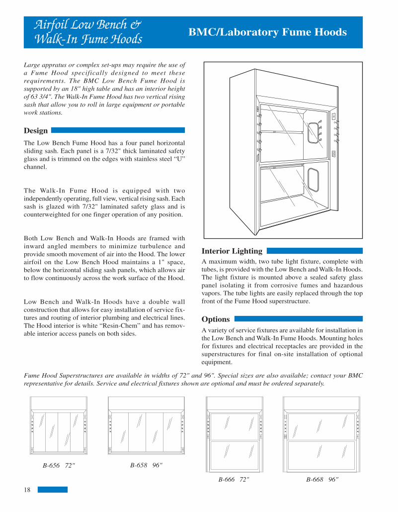
Fume Hood Superstructures are available in widths of 72" and 96". Special sizes are also available; contact your BMCrepresentative for details. Service and electrical fixtures shown are optional and must be ordered separately.
B-668 96"
BMC/Laboratory Fume HoodsAirfoil Low Bench &Walk-In Fume Hoods
B-656 72" B-658 96"
B-666 72"
Large appratus or complex set-ups may require the use ofa Fume Hood specifically designed to meet theserequirements. The BMC Low Bench Fume Hood issupported by an 18" high table and has an interior heightof 63 3/4". The Walk-In Fume Hood has two vertical risingsash that allow you to roll in large equipment or portablework stations.
Design
The Low Bench Fume Hood has a four panel horizontalsliding sash. Each panel is a 7/32" thick laminated safetyglass and is trimmed on the edges with stainless steel “U”channel.
The Walk-In Fume Hood is equipped with twoindependently operating, full view, vertical rising sash. Eachsash is glazed with 7/32" laminated safety glass and iscounterweighted for one finger operation of any position.
Both Low Bench and Walk-In Hoods are framed withinward angled members to minimize turbulence andprovide smooth movement of air into the Hood. The lowerairfoil on the Low Bench Hood maintains a 1" space,below the horizontal sliding sash panels, which allows airto flow continuously across the work surface of the Hood.
Low Bench and Walk-In Hoods have a double wallconstruction that allows for easy installation of service fix-tures and routing of interior plumbing and electrical lines.The Hood interior is white “Resin-Chem” and has remov-able interior access panels on both sides.
Interior LightingA maximum width, two tube light fixture, complete withtubes, is provided with the Low Bench and Walk-In Hoods.The light fixture is mounted above a sealed safety glasspanel isolating it from corrosive fumes and hazardousvapors. The tube lights are easily replaced through the topfront of the Fume Hood superstructure.
OptionsA variety of service fixtures are available for installation inthe Low Bench and Walk-In Fume Hoods. Mounting holesfor fixtures and electrical receptacles are provided in thesuperstructures for final on-site installation of optionalequipment.
18
PortableFume Hood
Rough-in Details
23
COLLARSIZE
1 1/2" DIA.
S.P.
FREEAIR
S.P.
.1
S.P.
.2
S.P.
.3
CFM
100
CFM
98
CFM
95
CFM
90
MODELNUMBER
B-1735-PH
S.P.
.4
CFM
85
S.P.
.5
CFM
80
B-1735-PH - HoodB-1735-PT - CountertopB-1735-PS - Mobile Stand
The amount of air being exhausted through the hood will vary depending on thelength and shape of the ductwork. The chart below shows the exhaust volume (CFM)at various static pressures. For installations requiring long runs of ductwork, a supple-mental exhaust system may be required.
Exhaust fan is 115 V, 60 CY, 2870 RPM
CFM AT STATIC PRESSURE SHOWN
BMC/Laboratory Fume Hoods
The BMC Portable Fume Hood features safety andconvenience. Mobile design allows the Portable Fume Hoodto be wheeled into a working position and moved back to astorage location when the task is complete. Clear view sideand back panels make the Portable Fume Hood ideallysuited for demonstrations. It also allows instructorobservation when being used as a student work station.
Design
The framework of the Portable Fume Hood is fully welded,painted square tubing. The upper metal housing contains asingle tube fluorescent light (bulb included), exhaust fan,light and fan switches, duplex outlet and a double sided gashose connector. The interior work surface is black epoxyresin and is enclosed with 1/4" plexiglass viewing panels.The front viewing panel is hinged for easy access.Additional features include locking swivel casters, six footlong power cord and six feet of 1 1/2" diameter flexibleexhaust duct.
inside 12-20 1/26/06, 11:33 AM7
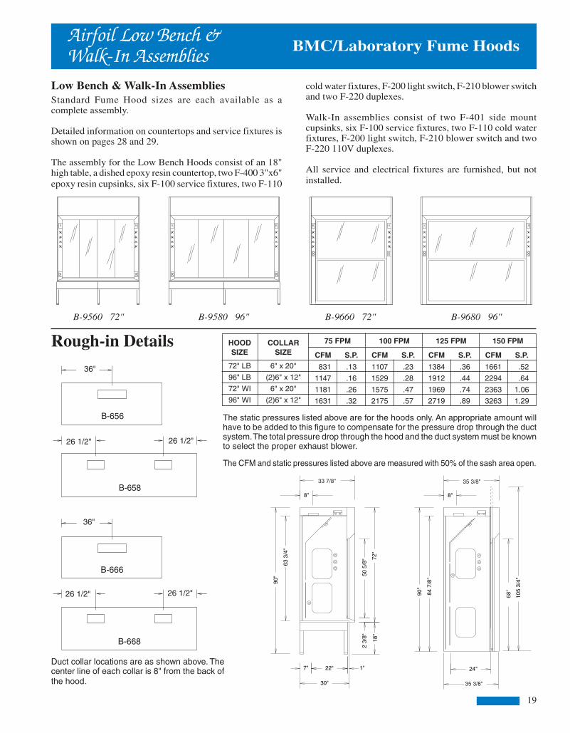
Low Bench & Walk-In AssembliesStandard Fume Hood sizes are each available as acomplete assembly.
Detailed information on countertops and service fixtures isshown on pages 28 and 29.
The assembly for the Low Bench Hoods consist of an 18"high table, a dished epoxy resin countertop, two F-400 3"x6"epoxy resin cupsinks, six F-100 service fixtures, two F-110
Rough-in Details
Duct collar locations are as shown above. Thecenter line of each collar is 8" from the back ofthe hood.
35"
25 1/2" 25 1/2"
35"
25 1/2" 25 1/2"
36"
26 1/2" 26 1/2"
36"
26 1/2" 26 1/2"
B-656
B-658
B-666
B-668
Airfoil Low Bench &Walk-In Assemblies BMC/Laboratory Fume Hoods
cold water fixtures, F-200 light switch, F-210 blower switchand two F-220 duplexes.
Walk-In assemblies consist of two F-401 side mountcupsinks, six F-100 service fixtures, two F-110 cold waterfixtures, F-200 light switch, F-210 blower switch and twoF-220 110V duplexes.
All service and electrical fixtures are furnished, but notinstalled.
B-9560 72" B-9580 96" B-9660 72" B-9680 96"
HOODSIZE
72" LB
96" LB
72" WI
96" WI
COLLARSIZE
6" x 20"
(2)6" x 12"
6" x 20"
(2)6" x 12"
75 FPM 100 FPM 125 FPM 150 FPM
CFM
831
1147
1181
1631
CFM
1107
1529
1575
2175
CFM
1384
1912
1969
2719
CFM
1661
2294
2363
3263
S.P.
.13
.16
.26
.32
S.P.
.23
.28
.47
.57
S.P.
.36
.44
.74
.89
S.P.
.52
.64
1.06
1.29
72"
50 5
/8"
22"
63 3
/4"
8"
7" 1"
30"
33 1/2"
18"
2 3/
8"
90"
105
3/4"
71"
24"
84 7
/8"
8"
35"
35"
90"
35 3/8"
68"
The static pressures listed above are for the hoods only. An appropriate amount willhave to be added to this figure to compensate for the pressure drop through the ductsystem. The total pressure drop through the hood and the duct system must be knownto select the proper exhaust blower.
The CFM and static pressures listed above are measured with 50% of the sash area open.
33 7/8" 35 3/8"
19
BMC/Laboratory Fume Hoods
COLLARSIZE
6" x 16"
6" x 16"
75 FPM 100 FPM 125 FPM 150 FPM
CFM
569
744
CFM
758
992
CFM
948
1240
CFM
1137
1488
S.P.
.20
.34
S.P.
.36
.61
S.P.
.56
.96
S.P.
.80
1.38
The static pressures listed above are for pressure drop through the hoods only. An appro-priate amount will have to be added to this figure to compensate for the pressure dropthrough the duct system. The total pressure drop through the hood and the duct systemmust be known to select the proper exhaust blower.
The CFM and static pressures listed above are measured with one sash open.
SIZE
48"
60"
DemonstrationFume Hoods
The BMC Demonstration Fume Hoods feature dual accesssashes and offer a clear, unobstructed view of the Hoodinterior.
DesignTwo independently operating sashes provide viewing andaccess from either side of the Demonstration Fume Hood.A fixed end window is also provided to increase theinterior viewing.
Sashes are glazed with laminated safety glass and have afull width PVC pull for maximum chemical resistance. TheHood interior is lined with chemical resistant “Resin-Chem”and is illuminated with a vapor proof incandescent lightfixture.
OptionsTwo 3-way switches, a blower switch and two duplexoutlets are available for installation on the DemonstrationHood. These items are optional and must be orderedseparately.
Rough-in Details MODELNUMBER
B-814
B-816
48"or
60"
22
inside 12-20 1/26/06, 11:33 AM8

BMC/Laboratory Fume Hoods
Interior LightingThe interior of the Thin Wall Fume Hood is brightly lit by avapor proof incandescent light fixture, bulb included.A single light fixture is provided in 48", 60" and 72"models and two fixtures are provided in the other models.Replacement of the incandescent bulbs is accomplishedfrom the interior of the Hood.
OptionsSwitches, outlets, and remote valves must be located on thefront panel of the Fume Hood base cabinet. Refer to pages28 and 29 for details.
Thin WallAssemblies
Thin Wall Fume Hood AssembliesThe five standard Fume Hood sizes are each available as acomplete assembly.
Detailed information on base cabinets and service fixturesis shown on pages 26, 28 and 29.
Assemblies for 48" and 60" wide Fume Hoods
Rough-in Details
B-9750 60" B-9760 72" B-9770 84"
Thin WallFume Hoods
The BMC Thin Wall Fume Hood provides an excellent lowcost means of exhausting high heat loads and non-hazardous fumes.
The Thin Wall design allows for maximum interior workarea and is well suited for installation on any counter of30" depth.
Design
The exterior of the Thin Wall Fume Hood is 18 gage steelwith an epoxy powder coat finish, front posts are stainlesssteel with a #4 finish. These components are attached to aheavy gage internal framework. This framework is weldedand bolted together to provide a ridged durable structurefor the Thin Wall Hood.
The interior of the Hood is lined with Minerit, a chemicalresistant gray composition stone material. The liner isattached to the internal framework with the use ofnon-metallic fasteners. A lintel, of the same material,restricts the air intake of the Hood to the sash opening. Thisrestriction allows you to vary the face velocity of the ThinWall Fume Hood by changing the sash position. Aninterior baffle system, also constructed of minerit,maintains a uniform face velocity across the entire openingof the sash. The upper portion of the baffle is adjustable tocompensate for high heat loads or light fumes.
The full view sash of the Thin Wall Hood is framed with achemical resistant black PVC. It is glazed with 7/32" thicklaminated safety glass and has a single counterweight foreasy up/down operations.
HOODSIZE
48"
60"
72"
84"
96"
COLLARSIZE
9" DIA.
10" DIA.
10" DIA.
(2) 9" DIA.
(2) 9" DIA.
75 FPM 100 FPM 125 FPM 150 FPM
CFM
710
904
1098
1292
1485
CFM
947
1206
1464
1722
1981
CFM
1184
1507
1830
2153
2476
CFM
1421
1808
2196
2583
2971
S.P.
.29
.30
.41
.25
.31
S.P.
.51
.54
.72
.45
.55
S.P.
.80
.84
1.13
.70
.86
S.P.
1.16
1.21
1.63
1.01
1.24
The static pressures listed above are for pressure drop through the hoods only. Anappropriate amount will have to be added to this figure to compensate for the pres-sure drop through the duct system. The total pressure drop through the hood and theduct system must be known to select the proper exhaust blower.
consist of a standard base cabinet, two LF35-7 fillerpanels, a 1" thick black epoxy resin countertop, F-200 lightswitch, F-210 blower switch and two F-220 110V duplexes.
72", 84" and 96" assemblies include all of the above alongwith a second base cabinet. Electrical fixtures are furnishedbut not installed.
B-838 96"
Fume Hood Superstructures are available in widths from 48" to 96", including BMC's unique 84" wide model as shownbelow. Service and electrical fixtures shown are optional and must be ordered separately.
B-834 48" B-835 60" B-836 72" B-837 84"
B-9740 48" B-9780 96"
Duct collar locations are as shown above. The center line of each collar is 8" from theback of the hood. The area indicated by the dashed lines is designated for plumbingand electrical rough-ins. All rough-ins should be kept within 7" of the wall and 18"from the floor.
B-834 B-835 B-836
B-837 B-838
24" 30" 36"
21 1/2" 21 1/2" 24 1/2" 24 1/2"
BMC/Laboratory Fume Hoods
20 21
inside 12-20 1/26/06, 11:33 AM9

BMC/Laboratory Fume Hoods
Interior LightingThe interior of the Thin Wall Fume Hood is brightly lit by avapor proof incandescent light fixture, bulb included.A single light fixture is provided in 48", 60" and 72"models and two fixtures are provided in the other models.Replacement of the incandescent bulbs is accomplishedfrom the interior of the Hood.
OptionsSwitches, outlets, and remote valves must be located on thefront panel of the Fume Hood base cabinet. Refer to pages28 and 29 for details.
Thin WallAssemblies
Thin Wall Fume Hood AssembliesThe five standard Fume Hood sizes are each available as acomplete assembly.
Detailed information on base cabinets and service fixturesis shown on pages 26, 28 and 29.
Assemblies for 48" and 60" wide Fume Hoods
Rough-in Details
B-9750 60" B-9760 72" B-9770 84"
Thin WallFume Hoods
The BMC Thin Wall Fume Hood provides an excellent lowcost means of exhausting high heat loads and non-hazardous fumes.
The Thin Wall design allows for maximum interior workarea and is well suited for installation on any counter of30" depth.
Design
The exterior of the Thin Wall Fume Hood is 18 gage steelwith an epoxy powder coat finish, front posts are stainlesssteel with a #4 finish. These components are attached to aheavy gage internal framework. This framework is weldedand bolted together to provide a ridged durable structurefor the Thin Wall Hood.
The interior of the Hood is lined with Minerit, a chemicalresistant gray composition stone material. The liner isattached to the internal framework with the use ofnon-metallic fasteners. A lintel, of the same material,restricts the air intake of the Hood to the sash opening. Thisrestriction allows you to vary the face velocity of the ThinWall Fume Hood by changing the sash position. Aninterior baffle system, also constructed of minerit,maintains a uniform face velocity across the entire openingof the sash. The upper portion of the baffle is adjustable tocompensate for high heat loads or light fumes.
The full view sash of the Thin Wall Hood is framed with achemical resistant black PVC. It is glazed with 7/32" thicklaminated safety glass and has a single counterweight foreasy up/down operations.
HOODSIZE
48"
60"
72"
84"
96"
COLLARSIZE
9" DIA.
10" DIA.
10" DIA.
(2) 9" DIA.
(2) 9" DIA.
75 FPM 100 FPM 125 FPM 150 FPM
CFM
710
904
1098
1292
1485
CFM
947
1206
1464
1722
1981
CFM
1184
1507
1830
2153
2476
CFM
1421
1808
2196
2583
2971
S.P.
.29
.30
.41
.25
.31
S.P.
.51
.54
.72
.45
.55
S.P.
.80
.84
1.13
.70
.86
S.P.
1.16
1.21
1.63
1.01
1.24
The static pressures listed above are for pressure drop through the hoods only. Anappropriate amount will have to be added to this figure to compensate for the pres-sure drop through the duct system. The total pressure drop through the hood and theduct system must be known to select the proper exhaust blower.
consist of a standard base cabinet, two LF35-7 fillerpanels, a 1" thick black epoxy resin countertop, F-200 lightswitch, F-210 blower switch and two F-220 110V duplexes.
72", 84" and 96" assemblies include all of the above alongwith a second base cabinet. Electrical fixtures are furnishedbut not installed.
B-838 96"
Fume Hood Superstructures are available in widths from 48" to 96", including BMC's unique 84" wide model as shownbelow. Service and electrical fixtures shown are optional and must be ordered separately.
B-834 48" B-835 60" B-836 72" B-837 84"
B-9740 48" B-9780 96"
Duct collar locations are as shown above. The center line of each collar is 8" from theback of the hood. The area indicated by the dashed lines is designated for plumbingand electrical rough-ins. All rough-ins should be kept within 7" of the wall and 18"from the floor.
B-834 B-835 B-836
B-837 B-838
24" 30" 36"
21 1/2" 21 1/2" 24 1/2" 24 1/2"
BMC/Laboratory Fume Hoods
20 21
inside 12-20 1/26/06, 11:33 AM9
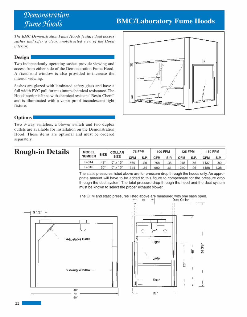
Low Bench & Walk-In AssembliesStandard Fume Hood sizes are each available as acomplete assembly.
Detailed information on countertops and service fixtures isshown on pages 28 and 29.
The assembly for the Low Bench Hoods consist of an 18"high table, a dished epoxy resin countertop, two F-400 3"x6"epoxy resin cupsinks, six F-100 service fixtures, two F-110
Rough-in Details
Duct collar locations are as shown above. Thecenter line of each collar is 8" from the back ofthe hood.
35"
25 1/2" 25 1/2"
35"
25 1/2" 25 1/2"
36"
26 1/2" 26 1/2"
36"
26 1/2" 26 1/2"
B-656
B-658
B-666
B-668
Airfoil Low Bench &Walk-In Assemblies BMC/Laboratory Fume Hoods
cold water fixtures, F-200 light switch, F-210 blower switchand two F-220 duplexes.
Walk-In assemblies consist of two F-401 side mountcupsinks, six F-100 service fixtures, two F-110 cold waterfixtures, F-200 light switch, F-210 blower switch and twoF-220 110V duplexes.
All service and electrical fixtures are furnished, but notinstalled.
B-9560 72" B-9580 96" B-9660 72" B-9680 96"
HOODSIZE
72" LB
96" LB
72" WI
96" WI
COLLARSIZE
6" x 20"
(2)6" x 12"
6" x 20"
(2)6" x 12"
75 FPM 100 FPM 125 FPM 150 FPM
CFM
831
1147
1181
1631
CFM
1107
1529
1575
2175
CFM
1384
1912
1969
2719
CFM
1661
2294
2363
3263
S.P.
.13
.16
.26
.32
S.P.
.23
.28
.47
.57
S.P.
.36
.44
.74
.89
S.P.
.52
.64
1.06
1.29
72"
50 5
/8"
22"
63 3
/4"
8"
7" 1"
30"
33 1/2"
18"
2 3/
8"
90"
105
3/4"
71"
24"
84 7
/8"
8"
35"
35"
90"
35 3/8"
68"
The static pressures listed above are for the hoods only. An appropriate amount willhave to be added to this figure to compensate for the pressure drop through the ductsystem. The total pressure drop through the hood and the duct system must be knownto select the proper exhaust blower.
The CFM and static pressures listed above are measured with 50% of the sash area open.
33 7/8" 35 3/8"
19
BMC/Laboratory Fume Hoods
COLLARSIZE
6" x 16"
6" x 16"
75 FPM 100 FPM 125 FPM 150 FPM
CFM
569
744
CFM
758
992
CFM
948
1240
CFM
1137
1488
S.P.
.20
.34
S.P.
.36
.61
S.P.
.56
.96
S.P.
.80
1.38
The static pressures listed above are for pressure drop through the hoods only. An appro-priate amount will have to be added to this figure to compensate for the pressure dropthrough the duct system. The total pressure drop through the hood and the duct systemmust be known to select the proper exhaust blower.
The CFM and static pressures listed above are measured with one sash open.
SIZE
48"
60"
DemonstrationFume Hoods
The BMC Demonstration Fume Hoods feature dual accesssashes and offer a clear, unobstructed view of the Hoodinterior.
DesignTwo independently operating sashes provide viewing andaccess from either side of the Demonstration Fume Hood.A fixed end window is also provided to increase theinterior viewing.
Sashes are glazed with laminated safety glass and have afull width PVC pull for maximum chemical resistance. TheHood interior is lined with chemical resistant “Resin-Chem”and is illuminated with a vapor proof incandescent lightfixture.
OptionsTwo 3-way switches, a blower switch and two duplexoutlets are available for installation on the DemonstrationHood. These items are optional and must be orderedseparately.
Rough-in Details MODELNUMBER
B-814
B-816
48"or
60"
22
inside 12-20 1/26/06, 11:33 AM8
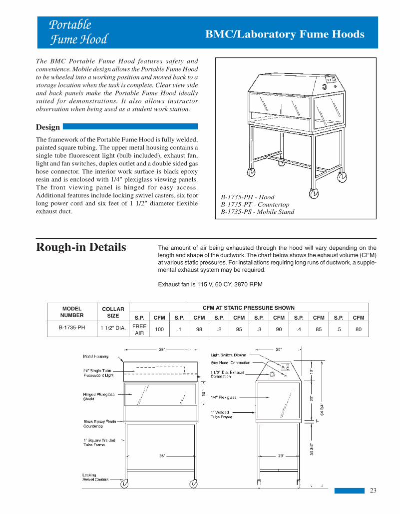
Fume Hood Superstructures are available in widths of 72" and 96". Special sizes are also available; contact your BMCrepresentative for details. Service and electrical fixtures shown are optional and must be ordered separately.
B-668 96"
BMC/Laboratory Fume HoodsAirfoil Low Bench &Walk-In Fume Hoods
B-656 72" B-658 96"
B-666 72"
Large appratus or complex set-ups may require the use ofa Fume Hood specifically designed to meet theserequirements. The BMC Low Bench Fume Hood issupported by an 18" high table and has an interior heightof 63 3/4". The Walk-In Fume Hood has two vertical risingsash that allow you to roll in large equipment or portablework stations.
Design
The Low Bench Fume Hood has a four panel horizontalsliding sash. Each panel is a 7/32" thick laminated safetyglass and is trimmed on the edges with stainless steel “U”channel.
The Walk-In Fume Hood is equipped with twoindependently operating, full view, vertical rising sash. Eachsash is glazed with 7/32" laminated safety glass and iscounterweighted for one finger operation of any position.
Both Low Bench and Walk-In Hoods are framed withinward angled members to minimize turbulence andprovide smooth movement of air into the Hood. The lowerairfoil on the Low Bench Hood maintains a 1" space,below the horizontal sliding sash panels, which allows airto flow continuously across the work surface of the Hood.
Low Bench and Walk-In Hoods have a double wallconstruction that allows for easy installation of service fix-tures and routing of interior plumbing and electrical lines.The Hood interior is white “Resin-Chem” and has remov-able interior access panels on both sides.
Interior LightingA maximum width, two tube light fixture, complete withtubes, is provided with the Low Bench and Walk-In Hoods.The light fixture is mounted above a sealed safety glasspanel isolating it from corrosive fumes and hazardousvapors. The tube lights are easily replaced through the topfront of the Fume Hood superstructure.
OptionsA variety of service fixtures are available for installation inthe Low Bench and Walk-In Fume Hoods. Mounting holesfor fixtures and electrical receptacles are provided in thesuperstructures for final on-site installation of optionalequipment.
18
PortableFume Hood
Rough-in Details
23
COLLARSIZE
1 1/2" DIA.
S.P.
FREEAIR
S.P.
.1
S.P.
.2
S.P.
.3
CFM
100
CFM
98
CFM
95
CFM
90
MODELNUMBER
B-1735-PH
S.P.
.4
CFM
85
S.P.
.5
CFM
80
B-1735-PH - HoodB-1735-PT - CountertopB-1735-PS - Mobile Stand
The amount of air being exhausted through the hood will vary depending on thelength and shape of the ductwork. The chart below shows the exhaust volume (CFM)at various static pressures. For installations requiring long runs of ductwork, a supple-mental exhaust system may be required.
Exhaust fan is 115 V, 60 CY, 2870 RPM
CFM AT STATIC PRESSURE SHOWN
BMC/Laboratory Fume Hoods
The BMC Portable Fume Hood features safety andconvenience. Mobile design allows the Portable Fume Hoodto be wheeled into a working position and moved back to astorage location when the task is complete. Clear view sideand back panels make the Portable Fume Hood ideallysuited for demonstrations. It also allows instructorobservation when being used as a student work station.
Design
The framework of the Portable Fume Hood is fully welded,painted square tubing. The upper metal housing contains asingle tube fluorescent light (bulb included), exhaust fan,light and fan switches, duplex outlet and a double sided gashose connector. The interior work surface is black epoxyresin and is enclosed with 1/4" plexiglass viewing panels.The front viewing panel is hinged for easy access.Additional features include locking swivel casters, six footlong power cord and six feet of 1 1/2" diameter flexibleexhaust duct.
inside 12-20 1/26/06, 11:33 AM7

Airfoil Perchloric Acid AssembliesThe five standard Fume Hood sizes are each available as acomplete assembly.
Detailed information on base cabinets, countertops andservice fixtures is shown on pages 26, 28 and 29.
The assembly for the 48" and 60" wide Hoods consists of astandard base cabinet, two LF35-7 filler panels, 3" x 6"
Rough-in Details
Airfoil PerchloricAcid Assemblies
The static pressures listed above are for the hoods only. An appropriate amountwill have to be added to this figure to compensate for the pressure drop throughthe duct system. The total pressure drop through the hood and the duct systemmust be known to select the proper exhaust blower.
Duct collar locations are as shown above. The center line of each collar is 8" fromthe back of the hood. The area indicated by the dashed lines is designated forplumbing and electrical rough-ins. All rough-ins should be kept within 7" of the walland 18" from the floor.
35"
22 1/2"
23 1/2"
22 1/2" 25 1/2" 25 1/2"
29"24" 30" 36"
B-644 B-645 B-646
23 1/2" 23 1/2" 26 1/2" 26 1/2"
B-647 B-648
COLLARSIZE
6" x 12"
6" x 16"
6" x 20"
(2)6" x 12"
(2)6" x 12"
75 FPM 100 FPM 125 FPM 150 FPM
CFM
650
850
1050
1250
1450
CFM
867
1133
1400
1667
1933
CFM
1083
1417
1750
2083
2417
CFM
1300
1700
2100
2500
2900
S.P.
.22
.21
.21
.21
.25
S.P.
.39
.38
.37
.37
.45
S.P.
.61
.59
.58
.58
.71
S.P.
.87
.85
.84
.83
1.02
HOODSIZE
48"
60"
72"
84"
96"
B-9440 48" B-9480 96"B-9470 84"B-9460 72"B-9450 60"
stainless steel cupsink, six F-100 service fixtures, F-110cold water fixture, F-200 light switch, F-210 blower switchand two F-220 110V duplexes.
72", 84" and 96" assemblies include all of the above alongwith a second base cabinet, cupsink and water fixture.
All service and electrical fixtures are furnished, but notinstalled.
BMC/Laboratory Fume Hoods
33 7/8"
89 1
/4"
31"
35"
17
OptionsOptional service and electrical fixtures are available for use withthe BMC Spray Booth. Contact your BMC representative toassist you in specifying these items.
The BMC Spray Booth offers an economical way to exhaustodors and non-toxic fumes in Laboratory, Class Room andShop environments.
Design
The BMC Spray Booth is constructed of 18 gage steel thatis formed and welded into a rigid superstructure. Each unitis finished with a chemical resistant powder coat paint fin-ish and has a replaceable, pleated air filter.
The Spray Booth is designed to have a non-explosion proofexhaust blower (specified on the next page) mounteddirectly on top of the unit. A rectangular duct transition isincluded to connect the exhaust blower to the Spray Booth.For flammable fumes or vapors, an optional explosion proofexhaust blower must be specified. The explosion proofexhaust blower is designed to be mounted on the roof orother suitable location, but not on top of the Spray Booth.
Interior LightingThe interior of the Spray Booth is illuminated by a vaporproof incandescent light fixture (bulb included). Light bulbreplacement is accomplished from the interior of the booth.
When exhausting flammable fumes or vapors, an optionalexplosion proof light fixture must be specified.
BMC/Laboratory Fume HoodsSpray Booth
Spray Booth Superstructures are available in widths from 24" to 48" as shown below.
B-810 24" B-811 30" B-812 36" B-813 48"
24
inside 12-20 1/26/06, 11:33 AM6

Interior LightingA two tube fluorescent light fixture illuminates the interior ofthe Perchloric Acid Fume Hood. The fixture is mounted behind asealed safety glass panel to isolate the fixture from corrosivefumes and flammable vapors. Replacement of fluorescent tubesis accomplished from the exterior top front of the Fume Hoodsuperstructure.
OptionsA variety of optional service fixtures are available from BMC.The location of the fixtures must be specified for accuratecutting of the mounting holes located in the Fume Hood lining.
Fume Hood Superstructures are available in widths from 48" to 96", including BMC's unique 84" wide model as shownbelow. Service and electrical fixtures shown are optional and must be ordered separately.
B-645 60"
BMC/Laboratory Fume HoodsAirfoil PerchloricAcid Fume Hoods
This Fume Hood is specifically designed for the use ofperchloric acid. A coved stainless steel liner with integralwork surface, an internal water wash down system andwater collection trough provide for detailed cleaning of theHood interior. In addition, the interior baffles are alsoremovable for cleaning to prevent the dangerous build-upof perchlorates.
Design
The Perchloric Acid Fume Hood has an internal bypasslocated above the sash. The bypass operates automatically,opening when the sash is closed and closing as the sash israised. The bypass provides for a relatively constant facevelocity at any sash position.
The sash frame and lower airfoil are constructed of type316 stainless steel. The sash is glazed with 7/32" thicklaminated safety glass and has full width pull andcounterweight for easy up/down operation. In the closedposition, the lower airfoil acts as a sash stop providing a 1"space for air to continuously sweep the work surfaces.
The interior liner, work surface and baffles are also con-structed of type 316 stainless steel. A wash down spray baris located behind the upper baffle for continuous cleaningbehind the baffles. A full width trough is located below thelower baffle to collect the wash down water from both theHood and ductwork.
Double wall constructin of the superstructure allows forinstallation of service fixtures and routing of interiorplumbing and electrical lines. Access for installation andmaintenance of service fixtures is obtained by removingthe exterior side panel.
B-648 96"B-647 84"B-646 72"B-644 48"
16
“A”
7"
7"
7"
7"
“C”
4 3/4"
7 3/4"
10 3/4"
19 3/4"
HOODSIZE
24"
30"
36"
48"
“B”
10 7/16"
8"
10 7/8"
10 7/8"
“D”
10 3/8"
14"
17 5/8"
26 5/8"
“E”
6"
6"
6 7/8"
6 7/8"
Exhaust Blowers
Exhaust Blowers feature a dynamically balanced forwardcurve wheel with cast iron hubs. Housing and motorbaseare 16 gage steel with a gray baked-on epoxy finish.
HOODSIZE
24"
30"
36"
48"
FILTERNUMBER
6556
6557
6558
6559
SIZE
16"X20"
22"X20"
14"X20"
20"X20"
Rough-in Details
QUANTITY
1
1
2
2
DIMENSIONS
Spray Booth BMC/Laboratory Fume Hoods
Motors are 115V/60HZ with H.P. as shown above.
Contact your BMC representative to assist you inspecifying an explosion proof exhaust blower.
CFM AT STATIC PRESSURE SHOWN
.125
560
920
968
1160
.375
470
820
890
1090
.625
360
710
810
963
.25
515
870
930
1125
.5
420
765
850
1035
.75
300
655
773
855
HOODSIZE
24"
30"
36"
48"
MODELNUMBER
7C037
7C038
7C039
7C647
OUTLETSIZE
4 1/4" x 7 3/8"
5 3/8" x 8 1/4"
6 1/2" x 10 3/4"
6 1/2" x 10 3/4"
HP
1/4
1/3
1/3
1/3
Replacement Filters
Spray Booth replacement filters are a 1" thickcotton polyester blended filter, laminated to a galvanizedsteel expanded metal support grid. Order by part numberfrom the chart to the left. (Note: 36" and 48" Spray Boothsrequire two filters.)
Plan View of Spray BoothTop Without Blower
5" x 10 7/8" See BlowerOutlet Size Above
Plan View of Spray BoothTop With Blower
B
AC
D
25
inside 12-20 1/26/06, 11:33 AM5

Airfoil Radio Isotope AssembliesThe five standard Fume Hood sizes are each available as acomplete assembly.
Detailed information on base cabinets, countertops andservice fixtures is shown on pages 26, 28 and 29.
The assembly for the 48" and 60" wide Hoods consists of astandard base cabinet, two LF35-7 filler panels, 3" x 6"
Rough-in Details
54 1
/4"
31"
22"48
"
8"
7" 1"
30"
33 1/2"
66 5
/8"
35 3
/4"
2 3/
8"
90"
35"
89 1
/4"
47"
33 7/8"
Airfoil RadioIsotope Assemblies BMC/Laboratory Fume Hoods
COLLARSIZE
6" x 12"6" x 16"6" x 20"
(2)6" x 12"(2)6" x 12"
75 FPM 100 FPM 125 FPM 150 FPM
CFM
650850
105012501450
CFM
8671133140016671933
CFM
10831417175020832417
CFM13001700210025002900
S.P.
.22
.21
.21
.21
.25
S.P.
.39
.38
.37
.37
.45
S.P.
.61
.59
.58
.58
.71
S.P..87.85.84.83
1.02
The static pressures listed above are for the hoods only. An appropriate amount willhave to be added to this figure to compensate for the pressure drop through theduct system. The total pressure drop through the hood and the duct system must beknown to select the proper exhaust blower.
Duct collar locations are as shown above. The center line of each collar is 8" fromthe back of the hood. The area indicated by the dashed lines is designated forplumbing and electrical rough-ins. All rough-ins should be kept within 7" of the walland 18" from the floor.
35"
22 1/2"
23 1/2"
22 1/2" 25 1/2" 25 1/2"
29"24" 30" 36"
23 1/2" 23 1/2" 26 1/2" 26 1/2"
B-634 B-635 B-636
B-637 B-638
HOODSIZE
48"60"72"84"96"
stainless steel cupsink, six F-100 service fixtures, F-110cold water fixture, F-200 light switch, F-210 blower switchand two F-220 110V duplexes.
72", 84" and 96" assemblies include all of the above alongwith a second base cabinet, cupsink and water fixture.
All service and electrical fixtures are furnished, but notinstalled.
B-9340 48" B-9350 60" B-9360 72" B-9370 84" B-9380 96"
15
BMC/Laboratory Fume Hoods
8"
18"
30"
CL
Canopy Hoods &Base Cabinets
Canopy Hoods
Canopy Hoods are specifically designed for exhausting non-hazardous materials such as heat, steam and odors.
Canopy Hoods are constructed of epoxy coated steel in any of our standard colors. Three sizes are available for wall orcorner mounting. Due to the many variations in wall and ceiling construction, mounting hardware is not included. Specialsize and configuration Canopy Hoods are available upon request.
The CFM listed above is based on 50 FPM with the Canopy Hood mounted 42" above the work surface and the front and oneside open. The static pressures shown are for the Hood only. An appropriate amount will have to be added to this figure tocompensate for the pressure drop through the duct system. The total pressure drop through the Hood and the duct systemmust be known to select the proper exhaust blower.
MODELNUMBER
B-7730
B-7740
B-7760
SIZE
36"
48"
72"
COLLARSIZE
12"
12"
12"
CFM
963
1138
1502
50 FPM
S.P.
.16
.17
.36
Flammable Storage Base Cabinets are constructed inaccordance with OSHA and NFPA requirements. Theyfeature double wall construction, panned bottom, full depthexpanded metal shelf, and a lockable three point door latch.Flammable storage cabinets are 18" deep.
Filler Panels are required to close off the pipe chase at theexposed end(s) of the base cabinet. Each filler panel comescomplete with clips, slip joint and hardware.
Fume Hood Base CabinetsBMC Fume Hood base cabinets feature heavy duty flushfront construction. Cabinet bottoms are panned up for easycleaning, cabinet backs are removable for access to servicelines. Doors are double pan, sound deadened constructionsupported with five knuckle stainless steel hinges. Shelvesare full depth and adjustable on 1" increments.
Cabinets are coated with a baked on epoxy finish in yourchoice of standard colors. Standard base cabinets are 22" deep.Acid storage and flammable storage cabinets are 18" deep.
Acid Storage Base Cabinets have a steel reinforcedpolyethylene lining, a full depth adjustable shelf andlouvered doors for ventilation.
LF35-7 7"LF35-11 11"
FSB3536-20018 36"FSB3548-20018 48"
B3536-20P 36"B3548-20P 48"B3558-20P 58"
ASB3536-20P18 36"ASB3548-20P18 48"
Flammable StorageBase Cabinet
26
Acid StorageBase Cabinet
Standard BaseCabinet
EndFiller Panels
* Threaded Rods NOT included
ACIDSTORAGE KEEP FIRE AWAY
FLAMMABLE
inside 12-20 1/26/06, 11:33 AM4
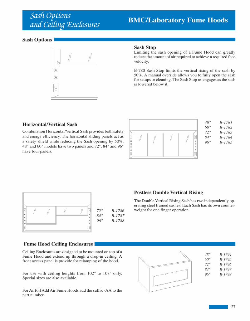
Interior LightingThe interior of the Radio Isotope Fume Hood is brightly lit bya maximum width dual fluorescent light fixture. The fixtureis mounted behind a sealed safety glass panel to isolate thefixture from corrosive fumes and flammable vapors.Replacement of fluorescent tubes is accomplished from theexterior top front of the Fume Hood superstructure.
OptionsOptional service and electrical fixtures are available forinstallation in the Radio Isotope Fume Hood. Mountingholes are provided in the superstructure for on-siteinstallation of the required service fixtures.
BMC/Laboratory Fume HoodsAirfoil RadioIsotope Fume Hoods
Stainless steel lining and work surface with coved cornersthat facilitate thorough cleaning and a reinforced countertopto support lead bricks, are some of the features incorpo-rated into the Radio Isotope Hood. These features will helpto insure operator safety and convenience in proceduresthat involve the use and handling of radioactive materials.
Design
The Radio Isotope Hood comes equipped with a type 304stainless steel sash frame with a full width flush pull andis glazed with 7/32" thick laminated safety glass. Acounterweight provides for one finger operation of the sashat any position. A lower stainless steel airfoil acts as a sashstop to maintain a 1" space, below the closed sash, whichallows air to continuously flow across the work surface.
The interior lining of the Radio Isotope Fume Hood is type304 stainless steel. All seams are welded and ground smoothto eliminate the build-up of radioactive materials. The worksurface, which is constructed of the same materials, iswelded to the lining, making the liner and work surfaceintegral and water tight. In addition, the work surface isreinforced to support 200 lbs. per square foot up to a totalweight of 1,000 lbs. per Hood or base cabinet section.
Double wall construction of the Hood superstructure allowsspace for installation of service fixtures. Access forinstallation and maintenance is acquired through theremovable stainless steel interior access panel or byremoving the exterior side panel of the superstructure. Abuilt-in bypass feature above the Hood sash works to maintaina relatively constant face velocity at any sash position.
Fume Hood Superstructures are available in widths from 48" to 96", including BMC's unique 84" wide model as shownbelow. Service and electrical fixtures shown are optional and must be ordered separately.
B-638 96"B-636 72" B-637 84"B-634 48" B-635 60"
14
Fume Hood Ceiling Enclosures
Ceiling Enclosures are designed to be mounted on top of aFume Hood and extend up through a drop-in ceiling. Afront access panel is provide for relamping of the hood.
For use with ceiling heights from 102" to 108" only.Special sizes are also available.
For Airfoil Add Air Fume Hoods add the suffix -AA to thepart number.
Sash Options
Horizontal/Vertical SashCombination Horizontal/Vertical Sash provides both safetyand energy efficiency. The horizontal sliding panels act asa safety shield while reducing the Sash opening by 50%.48" and 60" models have two panels and 72", 84" and 96"have four panels.
Sash Optionsand Ceiling Enclosures BMC/Laboratory Fume Hoods
Sash StopLimiting the sash opening of a Fume Hood can greatlyreduce the amount of air required to achieve a required facevelocity.
B-780 Sash Stop limits the vertical rising of the sash by50%. A manual override allows you to fully open the sashfor setups or cleaning. The Sash Stop re-engages as the sashis lowered below it.
Postless Double Vertical Rising
The Double Vertical Rising Sash has two independently op-erating steel framed sashes. Each Sash has its own counter-weight for one finger operation.
48" B-178160" B-178272" B-178384" B-178496" B-1785
48" B-179460" B-179572" B-179684" B-179796" B-1798
72" B-178684" B-178796" B-1788
27
inside 12-20 1/26/06, 11:33 AM3
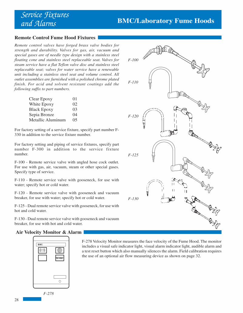
60 1
/4"
37"
22"54
"
8"
7" 1"
30"
33 1/2"
29 3
/4"
2 3/
8"
90"
Rough-in Details
89 1
/4"
33 7/8"
29"
Airfoil ADAAssemblies
The standard airfoil ADA Fume Hoods are each availableas a complete assembly.
Detailed information on base cabinets, countertops andservice fixtures is shown on pages 26, 28 and 29.
Each assembly includes two standard base cabinets (oneon 48" assembly), knee space area, two LF35-7 filler
BMC/Laboratory Fume Hoods
The static pressures listed above are for the hoods only. An appropriate amount willhave to be added to this figure to compensate for the pressure drop through the ductsystem. The total pressure drop through the hood and the duct system must be knownto select the proper exhaust blower.
The CFM and static pressures listed above are measures with 50% of the sash area open.
Duct collar locations are as shown above. The center line of each collar is 8" from the backof the hood. The area indicated by the dashed lines is designated for plumbing and electri-cal rough-ins. All rough-ins should be kept within 7" of the wall and 18" from the floor.
35"
22 1/2"
23 1/2"
22 1/2" 25 1/2" 25 1/2"
29"
23 1/2" 23 1/2" 26 1/2" 26 1/2"
B-684 B-685 B-686
B-687 B-688
panels, dished epoxy resin countertop, F-400 3" x 6" epoxyresin cupsink, three F-100 service fixtures, F-110 cold wa-ter fixtures, F-200 light switch, F-210 blower switch andtwo F-220 110V duplexes.
All service and electrical fixtures are furnished, but notinstalled.
B-9840 48" B-9850 60" B-9860 72" B-9880 96"
HOODSIZE
48"
60"
72"
84"
96"
COLLARSIZE
6" x 12"
6" x 16"
6" x 20"
(2)6" x 12"
(2)6" x 12"
75 FPM 100 FPM 125 FPM 150 FPM
CFM
325
425
525
625
725
CFM
433
567
700
833
967
CFM
542
708
875
1042
1208
CFM
650
850
1050
1250
1450
S.P.
.05
.05
.05
.05
.06
S.P.
.10
.09
.09
.09
.11
S.P.
.15
.15
.15
.14
.18
S.P.
.22
.21
.21
.21
.25
B-9870 84"
13
BMC/Laboratory Fume Hoods
F-100
F-278
Service Fixturesand Alarms
Remote Control Fume Hood Fixtures
Remote control valves have forged brass valve bodies forstrength and durability. Valves for gas, air, vacuum andspecial gases are of needle type design with a stainless steelfloating cone and stainless steel replaceable seat. Valves forsteam service have a flat Teflon valve disc and stainless steelreplaceable seat; valves for water service have a renewableunit including a stainless steel seat and volume control. Alloutlet assemblies are furnished with a polished chrome platedfinish. For acid and solvent resistant coatings add thefollowing suffix to part numbers.
Clear Epoxy 01White Epoxy 02Black Epoxy 03Sepia Bronze 04Metallic Aluminum 05
For factory setting of a service fixture, specify part number F-330 in addition to the service fixture number.
For factory setting and piping of service fixtures, specify partnumber F-300 in addition to the service fixturenumber.
F-100 - Remote service valve with angled hose cock outlet.For use with gas, air, vacuum, steam or other special gases.Specify type of service.
F-110 - Remote service valve with gooseneck, for use withwater; specify hot or cold water.
F-120 - Remote service valve with gooseneck and vacuumbreaker, for use with water; specify hot or cold water.
F-125 - Dual remote service valve with gooseneck, for use withhot and cold water.
F-130 - Dual remote service valve with gooseneck and vacuumbreaker, for use with hot and cold water.
TEST-RESET
B M C N a t i o n a l P r o d u c t s
Air Velocity Monitor & Alarm
F-278 Velocity Monitor measures the face velocity of the Fume Hood. The monitorincludes a visual safe indicator light, visual alarm indicator light, audible alarm anda test reset button which also manually silences the alarm. Field calibration requiresthe use of an optional air flow measuring device as shown on page 32.
F-110
F-120
F-125
F-130
28
24" 30" 36"
inside 12-20 1/26/06, 11:33 AM2

Interior LightingA fluorescent light fixture completed with tubes illuminatesthe interior of the ADA Fume Hood. The light fixture isisolated from the Hood interior by a sealed safety glasspanel. Relamping of the fixture is accomplished from thetop front of the superstructure.
OptionsIn addition to optional service and electrical fixtures for theADA Fume Hood, BMC also features an optional sash witha split viewing panel, secondary containment trough/airfoil, remote adjustable baffle, baffle screen, and air-flowmonitor. Any or all of these options can be incorporated tomeet specific needs or HOPEC requirements.
BMC/Laboratory Fume HoodsAirfoil ADAFume Hoods
BMC’s ADA Fume Hood is designed to meet the uniqueneeds of wheelchair operators. The ADA Fume Hooddelivers all the features and capabilities of our standardFume Hood line with special accommodations built in tomeet the specific requirements needed to provide a safe worksite for wheelchair operators.
Design
The Americans with Disabilities Act (ADA) prohibitsdiscrimination in hiring and promotion on the basis ofphysical disability. The BMC ADA Fume Hood is designedto provide a safe and comfortable work area for awheelchair bound person. The extended height of the sashalso makes the ADA Fume Hood a practical work stationfor a standing individual.
The ADA Fume Hood comes complete with a full framedcombination horizontal/vertical sliding sash. The sash isglazed with 7/32" laminated safety glass and is counter-weighted for one finger vertical operation. The fourhorizontal sliding panels glide on a dual track system foreasy access into the Hood.
Double wall construction of the Hood superstructure allowsfor easy installation of service fixtures and service lines.The entrance of the Hood is framed with inward angledmembers to provide for smooth movement of air into theHood. The interior lining is white “Resin-Chem” and has aremovable access panel on each interior side.
B-684 48" B-685 60" B-686 72" B-688 96"B-687 84"
Fume Hood Superstructures are available in widths from 48" to 96", including BMC's unique 84" wide model as shown below. Serviceand electrical fixtures shown are optional and must be ordered separately.
12
BMC/Laboratory Fume HoodsElectrical Fixturesand Countertops
Electrical Services
Flush mount electrical service fixtures come complete with devicebox and stainless steel face plate.
Explosion proof fixtures meet Class 1, Group C & D requirements.Explosion proof outlets and switches must be mounted on the frontpanel of the base cabinet or the exterior side of the Fume Hood.
For factory setting of electrical fixtures, specify part number F-340in addition to the electrical fixture number.
For factory setting and wiring of electrical fixtures, specify partnumber F320 in addition to the electrical fixturenumber.
Factory wiring of explosion proof fixtures on application only.
F-200 - Single pole light switch, 115 volt, 15 amp.
F-210 - Manual motor starter switch with pilot light, 115 volt, 15amp. Heating element not included.
F-220 - Duplex receptacle, 115 volt, 15 amp.
F-221 - Duplex receptacle, 115 volt, 20 amp.
F-225 - GFI duplex receptacle, 115 volt, 15 amp.
F-260 - Explosion proof light fixture, specify two fixtures on hoods84" and over.
F-262 - Explosion proof receptacle.
F-264 - Explosion proof switch.
Countertops
B-8040 48"B-8050 60"B-8060 72"B-8070 84"B-8080 96"
ALLEN-BRADLEY
RESET
F-200
F-264
F-210
F-225
F-260
F-262
F-220F-221
Fume Hood work surfaces are molded from amodified epoxy resin that has been especially compoundedand cured to provide optimum physical and chemicalresistance required for a heavy duty laboratory workingsurface. Countertops are 1" thick with a 3/8" deep dishingto contain spills and have a non-glaring black finish.
If sinks or cupsinks are required, specify location.Front
29
inside 12-20 1/26/06, 11:33 AM1

Airfoil Add AirAssemblies
Airfoil Add Air Hood AssembliesThe five standard Fume Hood sizes are each available as acomplete assembly.
Detailed information on base cabinets, countertops andservice fixtures is shown on pages 26, 28 and 29.
The assembly for the 48" and 60" wide Hoods consists of astandard base cabinet, two LF35-7 filler panels, dished
Rough-in Details
The static pressures listed above are for the hoods only. An appropriate amount will haveto be added to this figure to compensate for the pressure drop through the duct system.The total pressure drop through the hood and the duct system must be known to select theproper exhaust blower. Supply figures are based on 70% add air.
35"
22 1/2"
23 1/2"
22 1/2" 25 1/2" 25 1/2"
29"
Duct collar locations are as shown above. The center line of each collar is 8" from the backof the hood. The center line of the supply duct is 35 5/8" from the back of the hood. Thearea indicated by the dashed lines is designated for plumbing and electrical rough-ins. Allrough-ins should be kept within 7" of the wall and 18" from the floor.
54 1
/4"
31"
22"48
"
8"
7" 1"
30"
35 1/4"
40 1/2"
66 5
/8"
35 3
/4"
2 3/
8"
90" 24"
B-624 B-625 B-626
36"
23 1/2" 23 1/2"
B-627 B-628
26 1/2"26 1/2"
30"
35"
89 1
/4"
35 5/8"
40 7/8"
B-9280 96"B-9240 48"
COLLARSIZE
6" x 12"6" x 12"6" x 16"6" x 16"6" x 20"6" x 20"
(2)6" x 12"(2)6" x 12"(2)6" x 12"(2)6" x 14"
75 FPM 100 FPM 125 FPM 150 FPM
CFM650455850595
1050735
1250875
14501015
S.P..22.17.21.17.21.17.21.15.25.17
CFM867607
1133793
1400980
1667116719331353
CFM1083758
1417992
175012252083145824171691
CFM1300910
17001190210014702500175029002030
S.P..39.30.38.29.37.31.37.29.45.31
S.P..61.48.59.47.58.46.58.46.71.49
S.P..87.69.85.69.84.68.83.71
1.02.71
EXHSUPEXHSUPEXHSUPEXHSUPEXHSUP
HOODSIZE
48"
60"
72"
84"
96"
11
B-9270 84"B-9260 72"B-9250 60"
epoxy resin countertop, F-400 3" x 6" epoxy resin cupsink, sixF-100 service fixtures, F-110 cold water fixture, F-200 lightswitch, F-210 blower switch and two F-220 110V duplexes.
72", 84" and 96" assemblies include all of the above alongwith a second base cabinet, cupsink and water fixture.
All service and electrical fixtures are furnished, but notinstalled.
BMC/Laboratory Fume HoodsBMC/Laboratory Fume Hoods
F-425
Baths
F-420
Sinks, Drainsand Baths
Sinks
Sinks are available in a variety of sizes and configurations forinstallation in Fume Hoods.
F-400 - Oval epoxy resin cupsink, 3"x6", 1 1/2" NPT outletconnection.
F-401 - Oval polypropyene panel mount cupsink, 3"x6", withretainer nut, 1 1/2" NPT outlet connection.
F-402 - Rectangular epoxy resin cupsink, 13 3/4" x 4 1/2"x 5 1/2" with stainless steel straining screen, 1 1/2" NPT outlet.
F-410 - Drop-in epoxy resin sink, 16" x 12" x 8" Dp.
F-411 - Drop-in epoxy resin sink, 18" x 15" x 8" Dp.
F-412 - Drop-in epoxy resin sink, 24" x 16" x 8" Dp.
Baths
Baths are available in steam, hot water or electric. Each bathis furnished with four sets of concentric rings which are spacedon 1" increments up to 6" diameter. Baths are constructed of 20gauge, type 304 stainless steel and come complete with aremote valve for mounting in the post of the Fume Hood. Size is18" x 18".
F-430 SteamF-431 Hot WaterF-432 Electric
Drains and Traps
F-420 - Epoxy resin sink outlet with retainer nut, 1 1/2" NPToutlet connection.
F-425 - Polypropylene p-trap with adjustable riser, 1 1/2" NPToutlet connection.
F-400
F-402
F-410F-411F-412
30
inside 1-11 1/26/06, 11:33 AM11

Fume Hood Superstructures are available in widths from 48" to 96", including BMC's unique 84" wide model as shown below. Service andelectrical fixtures shown are optional and must be ordered separately.
Interior LightingThe interior of the Add Air Fume Hood is brightly lit by amaximum width dual fluorescent tube light fixture. The fixtureis mounted behind a sealed safety glass panel to isolate thefixture from corrosive fumes and flammable vapors.Replacement of fluorescent tubes is accomplished from theexterior top front of the Fume Hood superstructure.
OptionsChoose from the variety of optional service fixtures availablefrom BMC. Service fixture and electrical outlet types andlocations are to be specified by the customer to fit eachparticular application. Mounting holes are provided in thesuperstructure for final on-site installation of optional equipment.
B-628 96"
BMC/Laboratory Fume HoodsAirfoil Add AirFume Hoods
The BMC Airfoil Add Air Fume Hood provides addedeconomy through the use of a front mount “add airplenum” that can supply up to 70 percent of the total Hoodair volume requirement from an outside source.
Design
The superstructure entrance of the Add Air Fume Hood isframed with inward angled members that minimizeturbulence and provide smooth movement of air into theHood. This design allows for efficient operation of the FumeHood at face velocities ranging from 60 to 150 FPM.Additionally, the built-in bypass feature above the Hoodsash works to maintain a relatively constant face velocityat any sash position.
The front mounted add air plenum of the Airfoil Add AirFume Hood utilizes a series of diffusers and louvers toprovide a uniform flow of supply air to the face of the FumeHood. This uniform air flow allows for providing up to 70%of the overall air volume requirements of the Hood throughthe add air plenum.
As with other BMC Fume Hoods, the Add Air Hood comesequipped with a full view laminated safety glass sash witha full width flush pull and counterweight for easyoperation. A lower airfoil acts as sash stop that provides a1" space for air to continuously flow into the Hood andacross the work surface.
Double wall construction of the superstructure providesadequate space on both sides of the Hood for installation ofservice fixtures and routing of plumbing and electrical lines.The lining of the interior work area of the Hood is whiteResin-Chem with removable interior access panels on bothsides. Removable exterior side panels provide easy accessto fixtures and their service lines.
B-624 48" B-625 60"
10
B-626 72" B-627 84"
BMC/Laboratory Fume HoodsAccessoriesand Options
Vent Kits
F-440 Vent Kits are used to vent acid or flammable storagecabinets to the Fume Hood.
F-439
Material Options
The design of the BMC Fume Hoods allows for easysubstitution of standard components with optionalmaterials.
Interior linings are available in minerit, PVC or stainlesssteel in lieu of our standard Resin-Chem.
Sash options include full framed, painted or stainless steelsash.
Sash tracks and lower airfoils are both available instainless steel.
Contact your BMC representative to assist you inspecifying these items.
Baffle Options
Standard Fume Hoods are equipped with an adjustable upperbaffle only. Other adjustable baffle options are availableas follows:
B-790 Lower Adjustable BaffleB-791 Single Point Remote Adjustable Baffle for 48", 60" and 72" HoodsB-792 Single Point Remote Adjustable Baffle for 84" and 96" Hoods
F-440
31
Fire Extinguishers
F-439 Automatic Fire Extinguisher units are available for in-stallation in Fume Hoods. Fire Extinguishers are activated by afusible link. The link melts at 165º F, opening the valve whichreleased a multipurpose ABC Dry Chemical. Cylinders are con-structed of stainless steel and come complete with mountingbracket. Fume Hoods 72" and wider require the use of two FireExtinguishers for adequate projection.
inside 1-11 1/26/06, 11:33 AM10

Airfoil VariableVolume Assemblies
Airfoil Variable Volume AssembliesThe five standard Fume Hood sizes are each available as acomplete assembly.
Detailed information on base cabinets, countertops andservice fixtures is shown on pages 26, 28 and 29.
The assembly for the 48" and 60" wide Hoods consists of astandard base cabinet, two LF35-7 filler panels, dished
Rough-in Details
B-9140 48" B-9150 60" B-9180 96"
54 1
/4"
31"
22"48
"
8"
7" 1"
30"
33 1/2"
66 5
/8"
35 3
/4"
2 3/
8"
90"
89 1
/4"
35"
33 7/8"
BMC/Laboratory Fume Hoods
epoxy resin countertop, F-400 3" x 6" epoxy resin cupsink, sixF-100 service fixtures, F-110 cold water fixture, F-200 lightswitch, F-210 blower switch and two F-220 110V duplexes.
72", 84" and 96" assemblies include all of the above alongwith a second base cabinet, cupsink and water fixture.
All service and electrical fixtures are furnished, but notinstalled.
B-9160 72" B-9170 84"
HOODSIZE
48"
60"
72"
84"
96"
COLLARSIZE
6" x 12"
6" x 16"
6" x 20"
(2)6" x 12"
(2)6" x 12"
75 FPM 100 FPM 125 FPM 150 FPM
CFM
650
850
1050
1250
1450
CFM
867
1133
1400
1667
1933
CFM
1083
1417
1750
2083
2417
CFM
1300
1700
2100
2500
2900
S.P.
.22
.21
.21
.21
.25
S.P.
.39
.38
.37
.37
.45
S.P.
.61
.59
.58
.58
.71
S.P.
.87
.85
.84
.83
1.02
The static pressures listed above are for the hoods only. An appropriate amount willhave to be added to this figure to compensate for the pressure drop through the ductsystem. The total pressure drop through the hood and the duct system must beknown to select the proper exhaust blower.
Duct collar locations are as shown above. The center line of each collar is 8" fromthe back of the hood. The area indicated by the dashed lines is designated forplumbing and electrical rough-ins. All rough-ins should be kept within 7" of the walland 18" from the floor.
35"
22 1/2"
23 1/2"
22 1/2" 25 1/2" 25 1/2"
29"24" 30" 36"
23 1/2" 23 1/2" 26 1/2" 26 1/2"
B-614 B-615 B-616
B-617 B-618
9
BMC/Laboratory Fume Hoods
F-445
F-446
F-441
F-423F-424
F-422
F-417
F-416
Accessories
Lattice Assemblies
Lattice assemblies consist of the components listed below andcan be configured as required. Lattice rods come in standardlength and can be cut in the field for an exact fit.
F-441 36" x 1/2" DIA. RODF-442 48" x 1/2" DIA. RODF-443 72" x 1/2" DIA. RODF-444 96" x 1/2" DIA. RODF-445 CLAMP FOR 1/2" DIA. RODF-446 FOOT FOR 1/2" DIA. ROD
F-422 Hand held, rotating vane anemometer is ideal formonitoring Fume Hood face velocity. The unit which iscompletely self-contained is powered by a 9-volt battery and canbe operated with one hand.
Operation is simple, with a single push-button control in thehandle. When the button is depressed and held the unit willdisplay a digital read-out of the Fume Hood face velocity.
Smoke
A variety of smoke generating devices are available to monitorthe airflow into and around the Fume Hood.
F-415 Smoke sticks generate 2-3 minutes of continuous smokeand come in packages of 12.
F-416 Smoke bottle contains an ampule that, when broken,releases a dense white smoke.
F-417 Smoke cartridges generate 45 seconds of continuoussmoke and come in packages of 10.
Filters
F-415
Anemometer
Exhaust filters are used to entrap and retain airborne particles of contaminationat their source of origin, preventing the spread of contamination through the ductworkand through the point of discharge.Note: not recommended for use with radioisotopes
Filter housing assemblies consist of a stainless steel enclosure with a removable facepanel that permits installation of the pre-filter and HEPA filter.
F-423 Filter housing measures 25 13/16" x 23 7/8" x 24 3/8" and includes a 24" x 24"x 11 1/2" HEPA filter and pre-filter. Collar size is 10" Diameter.
F-424 Filter housing measures 31 13/16" x 30 3/8" x 24 3/8" and includes a 24" x 30"x 11 1/2" HEPA filter and pre-filter. Collar size is 12" Diameter.32
inside 1-11 1/26/06, 11:33 AM9
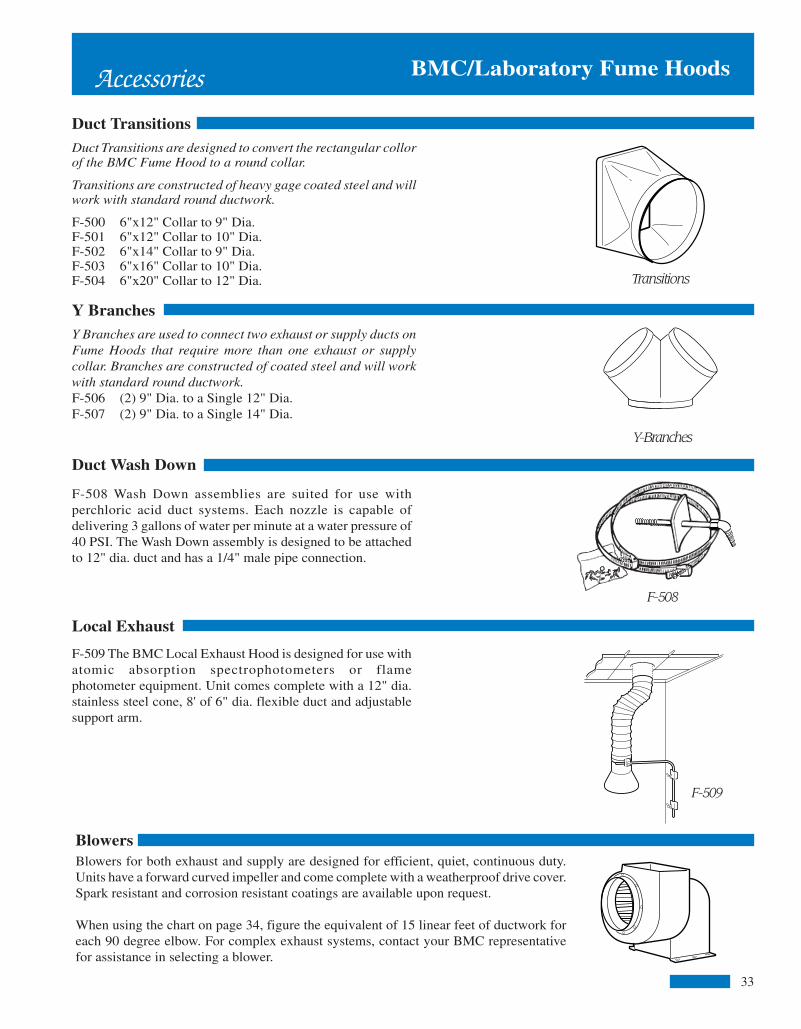
Airfoil VariableVolume Fume Hoods
Interior LightingA twin tube fluorescent light fixture provides illuminationof the Hood's interior surfaces. The fixture is recessed intothe interior Hood ceiling and protected behind a sealed safetyglass panel away from hazardous vapors and corrosivefumes. Tubes (included with Hood purchase) are easilyreplaced from the outside of the Hood superstructure.
OptionsA variety of optional service fixtures are available fromBMC for installation in the Variable Volume Fume Hood.Mounting holes for fixtures and electrical receptacles arepre-cut and capped when fixtures are not required.
Fume Hood Superstructures are available in widths from 48" to 96", including BMC's unique 84" wide model as shown below.Service and electrical fixtures shown are optional and must be ordered separately.
B-618 96"B-617 84"
BMC/Laboratory Fume Hoods
The Variable Volume Fume Hood is specifically designedfor use with exhaust control systems provided by othermanufacturers that monitor and control the amount of airbeing exhausted from the Hood. The use of these deviceswill maintain a constant face velocity and greatly reducethe operating cost of the Fume Hood.
Design
A lintel at the upper front of the superstructure restricts theHood air intake to the front sash opening. By incorporatingany one of a number of commercially available VAVcontrols, the exhaust volume of the Hood can be varied tomaintain a specified face velocity regardless of sashposition.
The full view sash provides a clear, unobstructed view ofthe work surface and when fully opened, allows easyaccess to all areas of the Hood interior. The sash iscounterweighted for easy up/down operation and is madeof 7/32" laminated safety glass with a full width flush pull.
The lower airfoil acts as a sash stop designed to provide a1" gap (with sash closed) allowing air to continuously sweepthe countertop of the Fume Hood.
Double side wall Hood construction providesadequate space for mounting service fixtures. The interior“Resin-Chem” lining has removable access panels oneither side providing easy access for installation andmaintenance of service and electrical fixtures. Bothexterior side panels of the Hood superstructure are alsoremovable for access to lines.
B-614 48" B-615 60" B-616 72"
8
BMC/Laboratory Fume HoodsAccessories
Duct Transitions
Duct Transitions are designed to convert the rectangular collorof the BMC Fume Hood to a round collar.
Transitions are constructed of heavy gage coated steel and willwork with standard round ductwork.
F-500 6"x12" Collar to 9" Dia.F-501 6"x12" Collar to 10" Dia.F-502 6"x14" Collar to 9" Dia.F-503 6"x16" Collar to 10" Dia.F-504 6"x20" Collar to 12" Dia.
Y Branches
Transitions
Y-Branches
Duct Wash Down
F-508 Wash Down assemblies are suited for use withperchloric acid duct systems. Each nozzle is capable ofdelivering 3 gallons of water per minute at a water pressure of40 PSI. The Wash Down assembly is designed to be attachedto 12" dia. duct and has a 1/4" male pipe connection.
F-508
BlowersBlowers for both exhaust and supply are designed for efficient, quiet, continuous duty.Units have a forward curved impeller and come complete with a weatherproof drive cover.Spark resistant and corrosion resistant coatings are available upon request.
When using the chart on page 34, figure the equivalent of 15 linear feet of ductwork foreach 90 degree elbow. For complex exhaust systems, contact your BMC representativefor assistance in selecting a blower.
Local Exhaust
F-509
F-509 The BMC Local Exhaust Hood is designed for use withatomic absorption spectrophotometers or flamephotometer equipment. Unit comes complete with a 12" dia.stainless steel cone, 8' of 6" dia. flexible duct and adjustablesupport arm.
33
Y Branches are used to connect two exhaust or supply ducts onFume Hoods that require more than one exhaust or supplycollar. Branches are constructed of coated steel and will workwith standard round ductwork.F-506 (2) 9" Dia. to a Single 12" Dia.F-507 (2) 9" Dia. to a Single 14" Dia.
inside 1-11 1/26/06, 11:44 AM8

Airfoil BypassAssemblies
Airfoil Bypass Fume Hood AssembliesThe five standard Fume Hood sizes are each available as acomplete assembly.
Detailed information on base cabinets, countertops andservice fixtures is shown on pages 26, 28 and 29.
The assembly for the 48" and 60" wide Hoods consists of astandard base cabinet, two LF35-7 filler panels, dished
Rough-in Details
Duct collar locations are as shown above. The center line of each collar is 8" from theback of the hood. The area indicated by the dashed lines is designated for plumbing andelectrical rough-ins. All rough-ins should be kept within 7" of the wall and 18" from thefloor.
B-9040 48" B-9050 60"
54 1
/4"
31"
22"48
"
8"
7" 1"
30"
33 1/2"
66 5
/8"
35 3
/4"
2 3/
8"
90"
35"
89 1
/4"
BMC/Laboratory Fume Hoods
The static pressures listed above are for the hoods only. An appropriate amount willhave to be added to this figure to compensate for the pressure drop through the ductsystem. The total pressure drop through the hood and the duct system must be known toselect the proper exhaust blower.
epoxy resin countertop, F-400 3" x 6" epoxy resin cupsink, sixF-100 service fixtures, F-110 cold water fixture, F-200 lightswitch, F-210 blower switch and two F-220 110V duplexes.
72", 84" and 96" assemblies include all of the above alongwith a second base cabinet, cupsink and water fixture.
All service and electrical fixtures are furnished, but notinstalled.
B-9060 72" B-9070 84" B-9080 96"
33 7/8"
HOODSIZE
48"
60"
72"
84"
96"
COLLARSIZE
6" x 12"
6" x 16"
6" x 20"
(2)6" x 12"
(2)6" x 12"
75 FPM 100 FPM 125 FPM 150 FPM
CFM
650
850
1050
1250
1450
CFM
867
1133
1400
1667
1933
CFM
1083
1417
1750
2083
2417
CFM
1300
1700
2100
2500
2900
S.P.
.22
.21
.21
.21
.25
S.P.
.39
.38
.37
.37
.45
S.P.
.61
.59
.58
.58
.71
S.P.
.87
.85
.84
.83
1.02
35"
22 1/2"
23 1/2"
22 1/2" 25 1/2" 25 1/2"
29"24" 30" 36"
23 1/2" 23 1/2" 26 1/2" 26 1/2"
B-604 B-605 B-606
B-607 B-608
BMC/Laboratory Fume Hoods
VELOCITYFPM
100100100100100
100SUPPLY
100SUPPLY
100SUPPLY
100SUPPLY
100SUPPLY
100100100100100
125125125125125
150150150150150
100100
100100
100100100100100
100100
505050
HOODMODEL NO.
B-604B-605B-606B-607B-608
B-624
B-625
B-626
B-627
B-628
B-684B-685B-686B-687B-688
B-634B-635B-636B-637B-638
B-644B-645B-646B-647B-648
B-656B-658
B-666B-668
B-834B-835B-836B-837B-838
B-814B-816
B-7730B-7740B-7760
AIRFOIL BYPASS FUME HOODS
AIRFOIL ADD AIR FUME HOODS
AIRFOIL ADA FUME HOODS
AIRFOIL RADIO ISOTOPE AIR FUME HOODS
AIRFOIL PERCHLORIC ACID FUME HOODS
AIRFOIL LOW BENCH FUME HOODS
AIRFOIL WALK-IN FUME HOODS
THIN WALL FUME HOODS
DEMONSTRATION FUME HOODS
CANOPY FUME HOODS
VOLUMECFM
8671133140016671933
867607
1133793
1400980
1667116719331353
433567700833967
10831417175020832417
13001700210025002900
11071529
15752175
9471206146417221981
758992
96311381502
DUCTDIA
9"10"12"12"14"
9"9"
10"10"12"12"12"12"14"14"
9"10"12"12"14"
9"10"12"12"14"
9"10"12"12"14"
10"12"
12"14"
9"10"12"12"14"
10"10"
12"12"12"
0-25 L/F OF DUCTBLOWER
9B11C12C12D15D
9B9A11C11A12C12A12E12B15D13C
8A8A9A11A9C
9D11E12E13F15E
GFE-12DGFE-12DGFE-12FGFE-15HGFE-15H
11C12D
12C15D
9C11D12D12E15D
11A11C
12A12B12D
RPM
1016882686725565
1016813882693686545747580565575
95011268266741064
12961155848821671
22002570272822592431
880700
705570
10781033836809570
750870
479580705
25-50 L/F OF DUCTBLOWER
9B11D12D12D15D
9B9A11D11A12D12A12E12B15D13C
8A8A9A11A9C
9D11E12E13F15E
GFE-12DGFE-12EGFE-12FGFE-15HGFE-15I
11D12D
12D12D
9C11D12E12E15D
11A11C
12A12B12D
RPM
1144981733747565
1144880981750733560788625565596
98511268266741064
13491195886876703
22002570288623962557
979769
740614
10781076877888611
764870
501625750
50-75 L/F OF DUCTRPM
12031026822788603
12038971026757822608868650603640
102011268266741064
14491267823933766
23822732288625222557
1020851
794649
10781117895886645
791870
523650836
75-100 L/F OF DUCT
BlowersBlowers
FAN SIZE9
11121315
GFE-12*GFE-15*
INLET9" DIA. OD10" DIA.OD
13 1/4" DIA. OD14 1/2" DIA. OD16 1/8" DIA. OD12 1/2" DIA. ID**15 1/2" DIA. ID**
OUTLET10 3/4" X 6 1/2" O.D.
11 3/4 X 8" O.D.13 1/4" X 9 5/8" O.D.
14 5/8" X 10 3/4" O.D.16 1/4" X 11 3/4" O.D.
13 1/2" X 18 1/8"O.D.**15 1/2" X 21 1/4" O.D.**
*=PVC Construction **=Flanged Connection
ELEC. REQUIREMENTSABCDEFGHI
VOLTAGE115/230, 1PH115/230, 1PH115/230, 1PH115/230, 1PH
200/208/460, 3PH200/208/460, 3PH200/208/460, 3PH200/208/460, 3PH200/208/460, 3PH
HORSEPOWER1/61/41/31/23/41
1 1/41 3/4
2
BLOWER
9D11D12D12D15D
9D9A11D11A12D12A12E12B15D13C
8A8A9A11A9C
9E11E12E13F15F
GFE-12EGFE-12FGFE-12GGFE-15IGFE-15I
11D12E
12D15E
9C11E12E12F15E
11A11C
12A12B12D
BLOWER
9C11D12D12D15D
9C9A11D11A12D12A12E12B15D13C
8A8A9A11A9C
9D11E12E13F15F
GFE-12DGFE-12FGFE-12FGFE-15IGFE-15I
11D12D
12D15E
9C11E12E12F15E
11A11C
12A12B12D
RPM
12811071865829603
12619741071822865668906677603685
105511268267461064
15431337923990766
23822732288626372600
1068900
877680
10781150915923652
822870
545677877
34 7
inside 1-11 1/26/06, 11:32 AM7
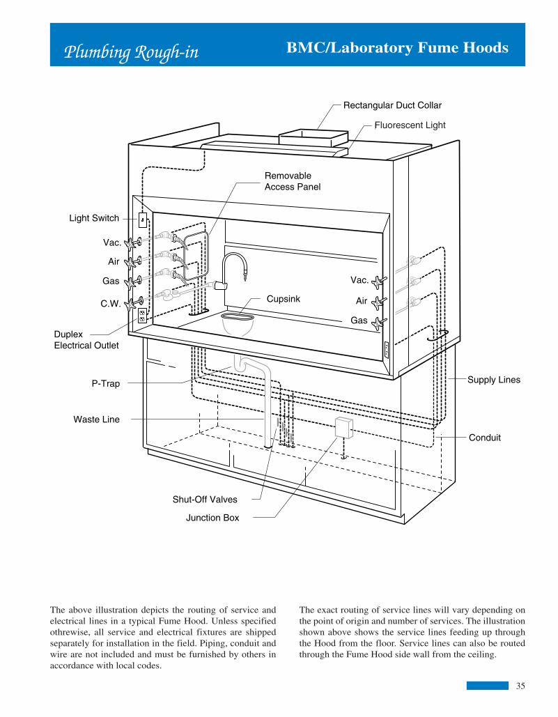
356
Interior LightingA maximum width, two tube fluorescent light fixture,complete with tubes, is provided with the Airfoil BypassFume Hood. The light fixture is mounted above a sealedsafety glass panel isolating it from corrosive fumes andhazardous vapors. Tube lights are easily replaced throughthe top front of the Fume Hood superstructure.
OptionsA variety of optional service fixtures are available fromBMC for installation in the Bypass Fume Hood. Our BMCrepresentatives work closely with customers in specifyingthe type of fixtures and electrical receptacles required.
B-608 96"
BMC/Laboratory Fume Hoods
Fume Hood Superstructures are available in widths from 48" to 96", including BMC's unique 84" wide model as shown below. Serviceand electrical fixtures shown are optional and must be ordered separately.
Airfoil BypassFume Hoods
Continuous air flow across the work surface of the AirfoilBypass Fume Hood exhausts potentially hazardous vaporssafely away from the work environment, even with the sashclosed!
The Airfoil Bypass Fume Hood features an internalbypass opening located above the sash allowing for aconstant exhaust volume while maintaining the facevelocity. In operation, the bypass works automatically, inconjunction with the hood sash. The bypass adjustment ismade as the sash is opened and closed creating a relativelyconstant face velocity regardless of sash position.
Design
The Bypass Fume Hood comes equipped with a full viewsash providing an unobstructed view of the Hood interiorwork area. The sash, a glazed 7/32" thick laminated safetyglass is provided with a full width flush pull. Acounterweight provides for one finger operation of the sashat any position.
The entrance of the Hood is framed with inward-angledmembers. This angled frame works to minimize turbulenceand provide smooth movement of air into the Hood,resulting in a more efficient operation of the Fume Hood atface velocities ranging from 60 to 150 FPM. A lowerairfoil sash stop maintains a 1" space (below closed sash)that allows air to flow continuously across the worksurface inside the Hood.
Double wall construction of the Hood superstructure allowsfor easy installation of service fixtures and routing ofinterior plumbing and electrical lines. The interior of theAirfoil Bypass Fume Hood is white “Resin-Chem.”Removable access panels on both interior sides of the Hoodare standard features. The exterior superstructure sidepanels are also removable for easy access to servicefixtures and supply lines.
B-604 48" B-605 60" B-606 72" B-607 84"
The above illustration depicts the routing of service andelectrical lines in a typical Fume Hood. Unless specifiedothrewise, all service and electrical fixtures are shippedseparately for installation in the field. Piping, conduit andwire are not included and must be furnished by others inaccordance with local codes.
Light Switch
Vac.
Vac.
Air
Air
Gas
Gas
C.W.
Duplex Electrical Outlet
Flourescent Light
Rectangular Duct Collar
Removable Access Panel
Cupsink
P-Trap
Waste Line
Supply Lines
Conduit
Shut-Off Valves
Junction Box
BMC/Laboratory Fume HoodsPlumbing Rough-in
Fluorescent Light
The exact routing of service lines will vary depending onthe point of origin and number of services. The illustrationshown above shows the service lines feeding up throughthe Hood from the floor. Service lines can also be routedthrough the Fume Hood side wall from the ceiling.
inside 1-11 1/26/06, 11:32 AM6
Figure 3 Figure 4 Figure 5
Planning BMC/Laboratory Fume Hoods
Whenever possible exhaust blowers should be located on the roofof the building. This will insure that the ductwork inside thebuilding will remain under negative pressure preventing leakageof contaminated air into occupied spaces.
Supply or add-air blowers may be located on the rooftop, sideledge, warehouse space or any other suitable location. The primeconcerns when locating the add-air blower is that it remain farenough away from other exhaust outlets to avoid cross-contamination. The other consideration is the temperature ofthe incoming air. Locating the add-air blower in an area ofsemi-conditioned air, like a warehouse, may provide a morecomfortable work area at the front of the Hood, while avoidingthe need to condition the supply air.
Add-Air Fume Hoods require the use of both an exhaust blowerand a supply blower. It is recommended that both blowers beconnected to a single on/off switch. This will avoid the possibilityof room contamination by turning on only the supply blower.
When using high concentrations of aerosols, solvents or otherflammable vapors inside the fume hood, an exhaust blower with anon-sparking wheel and explosion-proof motor may have to be used.
The duct material should be resistant to the materials used in theFume Hood. PVC, coated steel and stainless steel are all commonchoices. The ductwork should be installed with as few bends aspossible and have air tight joints.
Ducts are excellent conductors of sound. Anchoring the ductworksecurely to the building structure and sizing the ductwork so asnot to exceed velocities in excess of 2000 FPM will help toreduce duct noise.
The exhaust discharge should be located at least 10' above theroof structure and have a zero pressure weather cap. Coveredweather caps that increase static pressure and interfere with theflow of discharged air are not recommended.
As a rule, each Fume Hood should be exhausted by its ownexhaust blower, as shown in Figure 3. When multiple Hoods aremanifolded to a single exhaust blower, as shown infigure 4, imbalance in the exhaust airflow can occur as Hoods areturned on and off. To overcome this situation, all Hoods could be
turned on and off together. However, this may result in anunsatisfactory arrangement from the standpoint of energy efficiency.
Multiple Hoods which are controlled by a variable airvolume (VAV) control system may be manifolded to a singleexhaust blower. The VAV controls maintain the proper air balanceand provide excellent energy efficiency, by reducing the amountof air being exhausted when the Hood is not in use.
Care should be taken in the design of the VAV system. The airbeing supplied to the laboratory must also be variable to meet thechanging exhaust volume of the Fume Hoods. If not, overpressurization of the laboratory could occur causing contamina-tion of adjacent areas.
Because the exhaust volume of the VAV system can vary greatly,it is a good idea to select an exhaust blower with some type of airbypass, as shown in Figure 5. This will keep the fan motor fromoverloading and maintain an acceptable stack velocity.
Fume Hood blowers and ductwork systems should be included inthe maintenance schedule. Dust and other contaminants collectedon the blades of the fan can greatly reduce its capacity. Blowersshould be placed so that they are accessible for periodic cleaning.Periodic examination of the ductwork should also be made to de-tect any loose joints or porosity due to corrosion.
Fume Hood OperationA fume hood must be properly installed and operated in order toachieve optimum performance.
When using a Fume Hood, keep all apparatus at least 6" backfrom the face of the Hood. Do not put your head in the Hoodwhen contaminants are being generated. Do not store chemicalsor apparatus in the hood. Following these guidelines will helpinsure proper performance of the Fume Hood.
OSHA requires laboratories, where hazardous chemicals are used,to develop and carry out a written chemical hygiene plan. Thisplan should include provisions for monitoring fume hoods forproper performance, as well as periodic performance testing ofthe Fume Hoods. The Fume Hood air flow monitors, anemometerand smoke bombs shown on page 28 and 32 will help you meetthe requirements.
BMC/Laboratory Fume Hoods
heavy or light fumes. All baffles are removable forcleaning.
Unless specified for use in a variable air volume (VAV)system, the superstructures shall be provided with an airbypass feature. The bypass, located at the upper frontinterior of the Hood, shall open as the sash is lowered,providing for a relatively constant exhaust volume of theFume Hood superstructure
When specified, the upper front exterior panel of the super-structure can be furnished with louvers. The louversprovide for proper operation of the bypass feature when thetop of the superstructure is closed off to the ceiling.
A two tube, rapid start, vapor sealed fluorescent lightfixture of maximum length shall be provided on eachsuperstructure. Each fixture shall include two soft whitefluorescent tubes. Light fixtures are relamped from the topfront of the superstructure.
Exhaust outlets shall be rectangular, 18 gage stainless steel.Hoods with stainless steel interior liners shall have 18 gagestainless steel exhaust collars welded in place.
Fume Hoods shall have a full view, vertical rising,laminated safety glass sash framed with a solid black PVCedging. The sash shall have a full width finger lift with a 16gage internal support tube. The sash shall not require theuse of a center mullion. Sash guides shall be extruded, blackPVC.
The sash shall be counterbalanced with a single weightlocated in the center rear of the superstructure. Two 1/8"diameter stainless steel cables connect the sash to the weight.The use of two cables acts as a safety mechanism keeping thesash from falling in the event that one cable would fall. Thecables ride on 2" diameter nylon ball bearing pulleys. The cable/pulley assembly shall have an adjustment located on thetop of the superstructure for proper alignment of the sash.
A lower airfoil of 14 gage steel, coated with a black baked-on chemical resistant finish, shall act as the sash stop. Inaddition, the airfoil shall provide a 1" space between thebottom of the sash, in the closed position, and the worksurface. This 1" space shall provide for a continuous sweepof fumes from the work surface.
BMC Fume Hood Specifications
GeneralBMC Fume Hoods shall be of a “picture frame” air foildesign and construction. Each Fume Hood superstructureshall provide for safe efficient removal of all fumes, bothheavy and light, with the least amount of turbulence as theair enters the Hood.
Standard airfoil bench Hood superstructures are tested inaccordance with the current ASHRAE Test Procedureand perform well within the American Conference ofGovernmental Industrial Hygienists recommendations.
Material
Metal: Prime furniture steel, free of scales, buckles, or otherdefects; ASTM A366.
Stainless Steel: Type 304 or 316, as noted, commercialgrade. No. 4 Finish, ASTM A167.
Safety Glass: 7/32" Laminated; conforming to ANSI Z97.1for 400-foot-pound impact, and to CPSC 16 CFR 1201 forCategory II Safety Glazing.
PVC: Extruded Black PVC.
Resin-Chem: White chemical resistant, fiberglass reinforcedthermoset resin sheet.
ConstructionFume Hood superstructures have a double wallconstruction consisting of an outer shell of sheet steel andan inner liner of corrosion resistant material as specified.Attachment of the interior lining material to the steelframing members is made with non-metallic fasteners. Thedouble wall shall house and conceal steel framingmembers, attaching brackets and remote operating servicefixture valves.
The exterior side panels of the superstructure are constructedof 18 gage steel and are removable for access into theinterior housing. Access may also be gained throughremovable panels in the interior liner.
Each superstructure shall have an internal baffle system ofthe same material as the interior liner. This baffle systemshall provide for safe efficient removal of fumes when thesuperstructure is connected to a properly installed exhaustsystem. A manual adjustment is provided on the upper partof the baffle to allow the operator to set the Fume Hood for
Specifications
36 5
inside 1-11 1/26/06, 11:32 AM5

Figure 2 Poor Locations
The presence of cross-drafts will adversely affect theperformance or the Fume Hood. For this reason it is a good ideanot to locate the Fume Hood near open doors andwindows. High velocity air diffusers located directly in front ofthe Fume Hood could actually draw fumes out of the Hood andinto the room. Although there is no single preferred method fordelivery of make up air, it is a good idea to locate the Fume Hoodas far from the air diffuser as possible so that the air first sweepsthrough the laboratory working area and then into the Fume Hood.
Fume Hood Velocity SelectionSelection of the Fume Hood face velocity should be directly re-lated to the location of the Fume Hood. A Fume Hood in a goodlocation, as shown in Fig. 1, should operate properly at a facevelocity of 75 FPM. A poorly located Fume Hood, as shown inFig. 2, may require a face velocity of 125 FPM to maintain properperformance.
Since most fume hood installations require some type oflocation compromise, a face velocity of 100 FPM isusually the norm. Fume Hoods with a high heat source may re-quire slightly higher face velocities.
OSHA calls for, but does not require, a face velocity of 150 FPMfor Fume Hoods used with any of the 13 carcinogens listed inOSHA 1910.1003 et seq. (OSHA 1978). Studies have shown thathoods operated at face velocities of 150 FPM and greater oftenperform poorer than if operated at a lower face velocity, due todisruptive air turbulence at the perimeter of the Hood openingand in the wake of objects placed inside the work area of the Hood.
Fume Hood Blowers & DuctworkThe blower and ductwork control the amount of air moving throughthe Fume Hood. For this reason it is extremely important that theybe installed and maintained properly.
By using the chart on page 34, you can choose the correct blowerfor the Fume Hood you have selected.
Lineof
Traffic
Lineof
Traffic
Air ConditioningRegister
Hood
Center Table
Hood Base Cabinets
Base Cabinets
Sealed Windows
BMC/Laboratory Fume HoodsPlanning
Figure 1 Good Locations
Fume Hood SelectionThere are two main factors to consider when selecting a FumeHood style.
First consider the type of work being performed in the Hood. Theuse of perchloric acid or radioactive materials require a Fume Hoodspecifically designed for these materials. Large apparatus orcomplex set-ups may require the use of a low bench or walk-inFume Hood to accommodate the space requirements.
The second consideration in selecting a Fume Hood style is theair consumption of the hood. Operation of a Fume Hoodrequires a relatively large volume of room air.
If you determine that the amount of air being supplied to the roomis adequate to accommodate the exhaust volume of the Fume Hoodthe ByPass style Fume Hood would be an excellent choice.
If there is not enough supply air available, the Add Air style maybe the right choice.
The Variable Air Volume style Fume Hood is designed to be usedwith an adjustable damper system in the ductwork. The use of thisHood will, when used in conjunction with a VAV control system,drastically reduce the total amount of air consumed. This makesthe Variable Air Volume style Hood a good choice when trying toreduce air consumption for energy cost savings or when theresimply is not enough available supply air.
For more information see “Flow Patterns” on Page 3.
Fume Hood LocationsLocation of the Fume Hood is of prime importance, since a varietyof conditions will affect the performance of the Hood.
When selecting a location for the Fume Hood, operatorconvenience, work flow and exhaust duct locations should all beconsidered. In addition, an attempt should be made to keep thehood away from the line of traffic. It is both inconvenient anddangerous to install a Fume Hood so that the operator is forced towork in the line of traffic movement.
Lineof
Traffic
Lineof
TrafficAir ConditioningRegisters
HoodHood
CenterTable
CenterTable
Base Cabinets
Sealed Windows
4
BMC/Laboratory Fume HoodsSpecifications
Airfoil Bypass Fume HoodsConstructed as specified above. The Airfoil Bypass FumeHood superstructure has a white Resin-Chem interior lin-ing.
Airfoil Add Air Fume Hoods
The Add Air superstructure shall have an 18 gage, paintedsteel add air plenum. The plenum shall be capable of prop-erly distributing up to 70% of the air requirements of theHood. The add air plenum shall be of standard size and canbe added to any of the standard BMC Fume Hoods.
The interior lining of the Airfoil Add Air Fume Hood su-perstructure shall be white Resin-Chem.
Airfoil Radio Isotope Hoods
The interior lining and work surface of the Radio Isotopesuperstructure shall be type 304 stainless steel. Seams andjoints present in the interior and work surface shall bewelded to eliminate pockets, cracks and crevices that wouldpermit a buildup of radioactive materials.
The work surface shall be an integral welded part of thesuperstructure. It shall be watertight and furnished with araised edge to contain spills. It shall be properly reinforcedto support 200 lbs. per square foot up to a total weight of1,000 lbs. per Hood or base cabinet section.
An 18 gage type 304 stainless steel frame shall encase thelaminated safety glass sash. The vertical sliding sash shallride in type 304 stainless steel sash guides.
Interior removable access panels are provided for access tothe interior housing.
All other features of the Hood are as specified under "Con-struction."
Airfoil Perchloric Acid Fume Hoods
Perchloric Acid Fume Hood superstructures shall beidentified by a label indicating suitability for use withperchloric acid procedures. All exposed parts of thesuperstructure interior shall be seamless welded covedcornered, type 316, stainless steel.
The work surface shall an integral welded part of thesuperstructure. It shall be watertight and furnished with araised edge to contain spills. A full width drain through shallbe located below the baffle.
A water spray (wash down system) shall be provided forrinsing the area behind the baffle. Service fitting controlsfor the wash down system shall be external to the Hood,clearly identified and within easy reach.
An 18 gage, type 316 stainless steel frame shall encase thelaminated safety glass sash. The vertical sliding sash shallride in type 316, stainless steel sash guides.
Interior removable access panels are not provided onPerchloric Acid superstructures.
All other features of the Hood are as specified under"Construction."
Low Bench Hoods
Low Bench Fume Hood superstructures shall have a whiteResin-Chem interior lining. The sash shall consist of fourhorizontal sliding, laminated safety glass panels, with astainless steel edge trim. The panels shall ride on two tracksof extruded aluminum.
Two removable interior panels shall be located on each sideof the Fume Hood superstructure.
All other fixtures of the Low Bench Fume Hoodsuperstructure are specified under "Construction."
Walk-In Fume Hoods
Walk-In Fume Hood superstructures shall have awhite Resin-Chem interior lining. The sash shall consist oftwo vertical sliding, laminated safety glass panels as specifiedunder "Construction."
Two removable interior access panels shall be located oneach side of the Fume Hood superstructure.
All other features of the Walk-In Fume Hoodsuperstructure are as specified under "Construction."
37
inside 1-11 1/26/06, 11:32 AM4

Flow Patterns
Airfoil Bypass Hoods
The Airfoil Bypass Hoods have a double bypass to provideconstant exhaust volume and limit changes in face velocity.
The upper bypass functions automatically with the raising andlowering of the sash. The lower bypass provides a continuousair sweep of the work surface.
When hood top enclosures are used, a bypass grille must bespecified.
Airfoil Variable Air Volume Hoods
The Variable Air Volume (VAV) Hoods are designed to be usedwith exhaust control systems provided by other manufacturers.
In lieu of an upper bypass the VAV Hood has a lintel whichrestricts the air intake of the Hood to the sash opening and lowerbypass.
The commercially available exhaust control system will detectthe movement of the sash and adjust the volume of air requiredto maintain a constant face velocity.
Factory mounting of the exhaust controls is available whenspecified.
Airfoil Add Air Hoods
The Add Air Hoods provide up to 70% of the Hood exhaustrequirements. With a bypass similar to the Airfoil Bypass Hood,outside air is introduced through the add air plenum, thusminimizing the amount of conditioned room air required.
When outside temperatures are extreme, it may be necessary totemper the incoming air.
BMC/Laboratory Fume Hoods
Sash Closed Sash Open
Sash Closed Sash Open
3
Sash Closed Sash Open
BMC/Laboratory Fume HoodsDefinitions
Exhaust Collar – Connection between exhaust duct andFume Hood through which all exhaust air passes.
Face Velocity – Speed of air moving into Fume Hoodentrance or access opening, expressed in feet per minute(FPM).
Liner - Interior lining used for side, back, top enclosurepanels, exhaust plenum and baffle system of a laboratoryFume Hood.
Lintel - Portion of laboratory Fume Hood front locateddirectly above the access opening.
Resin-Chem - White chemical resistant fiberglassreinforced thermoset resin sheet.
Sash - Movable transparent panel set in Fume Hoodentrance.
Service Fitting - Fixture laboratory plumbing mounted onthe Fume Hood intended to control the supply of piped gasesand liquids for laboratory use.
Static Pressure - Air pressure in laboratory Fume Hood orduct, usually expressed in inches of water.
Static Pressure Loss - Measurement of resistance createdwhen air moves through a duct or hood, usually expressedin inches of water.
Superstructure - That portion of a laboratory Fume Hoodthat is supported by the countertop.
Add Air - Supply air delivered to a laboratory Fume Hoodto reduce room air consumption..
Air Foil – Curved or angular members at the Fume Hoodentrance.
Air Volume – Quanity of air normally expressed in cubicfeet per minute (CFM).
ASHRAE - American Society of Heating, Refrigerating andAir Conditioning Engineers.
Baffle - Panel located across the Fume Hood interior backwhich controls the pattern of air moving into and throughthe Fume Hood.
Blower - Air moving device, sometimes called a fan,consisting of a motor, impeller and housing.
Bypass - Compensating opening that maintains a relativelyconstant volume exhaust through a Fume Hood regardlessof sash position and that functions to limit the maximumface velocity as the sash is lowered.
Canopy Hood - Suspended ventilating device for non-critical use to exhaust only heat, water vapor and odors.
Countertop - Work surface resting on a base cabinet.
Duct - Round, square or rectangular tube used to enclosemoving air.
Duct Velocity - Speed of air moving in a duct, usuallyexpressed in feet per minute (FPM).
38
inside 1-11 1/26/06, 11:32 AM3

Introduction
you with maximum safety at minimum cost.Incorporating standard options, such as combinationsashes and sash stops, allows you to maintain facevelocities while exhausting less air. Hence, the BMC FumeHood costs less to operate than other conventional units.
REFERENCES – The American Industrial HygieneAssociation, The American Conferences of GovernmentalIndustrial Hygienists and the American Society ofHeating, Refrigerating and Air-Conditioning Engineershave all published guidelines on Fume Hood facevelocities and operating procedures.
Because the performance of a Fume Hood is greatlyaffected by the surrounding conditions, the recommendationsin this catalog are based on normal or averageconditions. For recommendations on ideal or extremeconditions, the guidelines published by the abovereferenced agencies should be followed.
SPECIFICATIONS – BMC Fume Hoods are manufacturedin strict accordance with the specifications shown in thiscatalog. However, continuous testing and research mayresult in design and specification changes withoutadvance notice.
BMC/Laboratory Fume Hoods
2
GENERAL – The name BMC has long been synonymouswith quality and longevity. Our newly redesigned FumeHood is a proud example of this reputation. Over 50 yearsof experience, combined with state-of-the-artengineering and testing facilities, provide you with aFume Hood unsurpassed in quality and performance.
TESTING – Safety should be the number one concernwhen choosing a Fume Hood. That is why BMC testsand certifies each style Fume Hood in accordance withthe current ASHRAE method of testing performance oflaboratory Fume Hoods.
The ASHRAE 110 test procedure is an industrystandard, recognized by SEFA and the AmericanConference of Governmental Industrial Hygienists, forsafe Fume Hood performance.
Our test facility is available for you to witness theASHRAE test procedure or to test special designs. Tomake arrangements to visit our test facility, contact yourlocal BMC Representative or our Main Office inMuskegon, MI.
DESIGN – The design of the BMC Fume Hood provides
BMC/Laboratory Fume Hoods
NOTES:
39
inside 1-11 1/26/06, 11:32 AM2

Airfoil
ADA Fume Hoods.............................................................12
ADA Fume Hood Assemblies............................................13
Add Air Fume Hoods........................................................10
Add Air Fume Hood Assemblies........................................11
Bypass Fume Hoods........................................................... 6
Bypass Fume Hood Assemblies......................................... 7
Low Bench Fume Hoods....................................................18
Low Bench Fume Hood Assemblies.................................19
Perchloric Acid Fume Hoods............................................16
Perchloric Acid Fume Hood Assemblies...........................17
Radio Isotope Fume Hoods................................................14
Radio Isotope Fume Hood Assemblies..............................15
Variable Volume Fume Hoods........................................... 8
Variable Volume Fume Hood Assemblies........................... 9
Walk-In Fume Hoods.........................................................18
Walk-In Fume Hood Assemblies........................................19
Alarms...................................................................................28
Anemometer..............................................................................32
Baffle Options.........................................................................31
Base Cabinets.........................................................................26
Baths.......................................................................................30
Blowers..............................................................................33-34
Canopy Hoods.........................................................................26
Ceiling Enclosures..................................................................27
Countertops.............................................................................29
Definitions.............................................................................38
1
Demonstration Fume Hood....................................................22
Drains....................................................................................30
Electrical Fixtures...................................................................29
Filler Panels............................................................................26
Filters.....................................................................................32
Fire Extinguishers..................................................................31
Flow Patterns......................................................................... 3
Introduction........................................................................... 2
Lattice Assemblies.................................................................32
Local Exhaust.........................................................................33
Material Options.....................................................................31
Planning................................................................................. 4
Plumbing Rough-In................................................................35
Portable Fume Hood...............................................................23
Sash Options..........................................................................27
Service Fixtures.......................................................................28
Sinks......................................................................................30
Smoke....................................................................................32
Specifications..........................................................................36
Spray Booth.......................................................................24-25
Thin Wall Fume Hood............................................................20
Thin Wall Fume Hood Assemblies........................................21
Transitions..............................................................................33
Traps........................................................................................30
Vent Kits..................................................................................31
Wash Down............................................................................33
Y Branches.............................................................................33
Table of Contents BMC/Laboratory Fume HoodsBMC/Laboratory Fume Hoods
NOTES:
40
inside 1-11 1/26/06, 11:32 AM1

BMCLaboratory Fume Hoods
Represented By:
BMCP.O. Box 4089Muskegon MI 49444Telephone: (231) 733-1206FAX: (231) 733-2116e-mail: [email protected] page: www.bmclab.com
© BMC 2006
M E M B E R
SEFASCIENTIFIC
EQUIPMENT &
FURNITURE
ASSOCIATION
Cover 1/27/06, 11:12 AM1