Embed Size (px)
Citation preview
1
Rajib MallCSE DepartmentIIT KHARAGPUR
Object-Oriented Design using UML
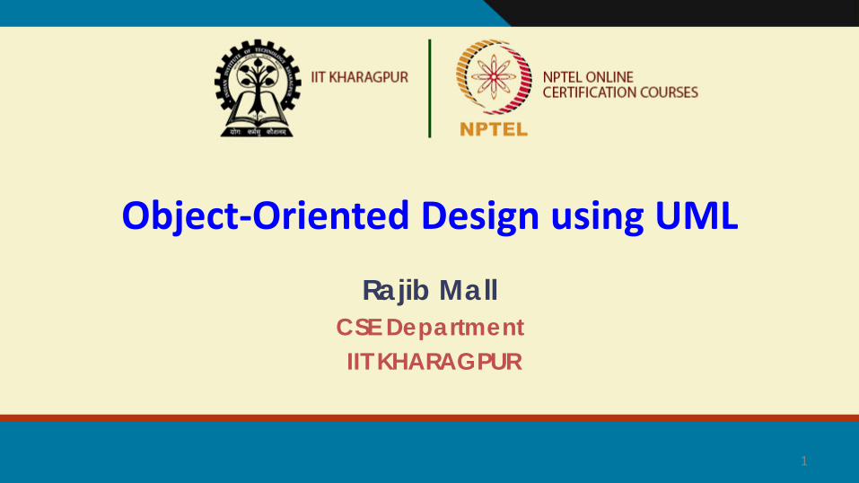
Introduction• Object-oriented design (OOD) techniques are now extremely
popular:
–Inception in early 1980’s and nearing maturity.
–Widespread acceptance in industry and academics.
–Unified Modelling Language (UML) became an ISO standard (ISO/IEC 19501) in 2004.
• UML is a modelling language.• Not a system design or development methodology
• Used to document object-oriented analysis and design results.
• Independent of any specific design methodology.
Object Modelling Using UML
• OOD in late 1980s and early 1990s:− Different software development houses were using different
notations.− Methodologies were tied to notations.
• UML developed in early 1990s:− To standardize the large number of object-oriented modelling
notations that existed.
UML Origin
• Based Principally on:− OMT [Rumbaugh 1991]
− Booch’s methodology[Booch 1991]
− OOSE [Jacobson 1992]
− Odell’s methodology[Odell 1992]
− Shlaer and Mellor [Shlaer 1992]
UML Lineology

Different Object Modeling
Techniques in UML
UMLBooch’s
MethodologyOOSE
OMT
• Adopted by Object Management Group (OMG) in 1997.
• OMG is an association of industries
• Promotes consensus notations and techniques
• UML also being used outside software development area:
−Example car manufacturing
UML as A Standard

Industrialization
Standardization
Unification
Fragmentation
History of UML
Other methods Booch'91 OMT-1 OOSE
Booch'93 OMT-2
UML 0.9 & 0.91
Unified method 0.8
UML 0.9 & 0.91
UML 1.1
public feedback
UML 2.0
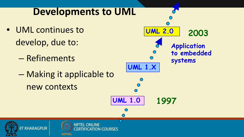
Developments to UML
• UML continues to develop, due to:
– Refinements
– Making it applicable to new contexts
UML 1.X
UML 1.0
UML 2.0
Application to embedded systems
1997
2003

Modelling is an abstraction mechanism:
−Capture only important aspects and ignores the rest.−Different models obtained when different aspects are ignored.
−An effective mechanism to handle complexity.UML is a graphical modelling technique
Easy to understand and construct
Why are UML Models Required?
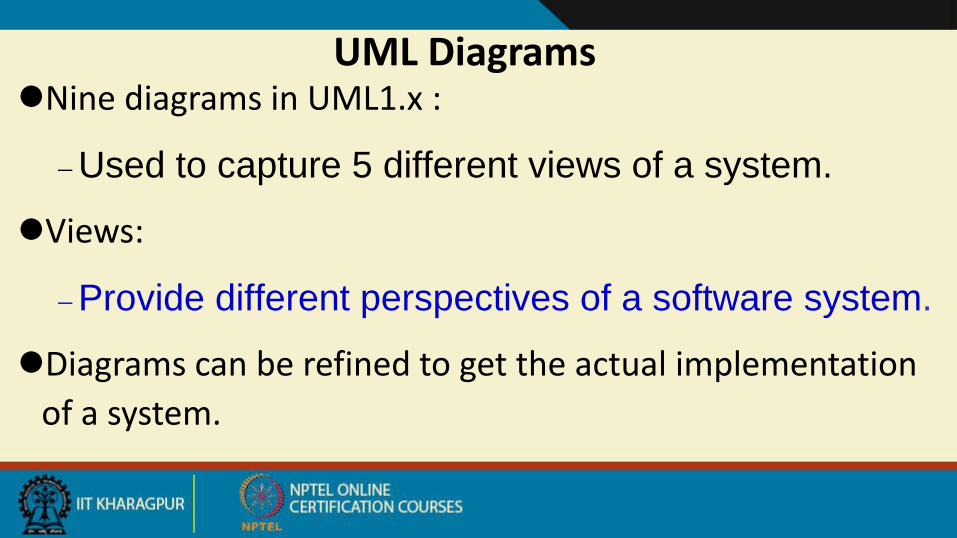
Nine diagrams in UML1.x :
−Used to capture 5 different views of a system.
Views:
−Provide different perspectives of a software system.
Diagrams can be refined to get the actual implementation of a system.
UML Diagrams

Views of a system:−User’s view
−Structural view
−Behavioral view
− Implementation view
−Environmental view
UML Model Views
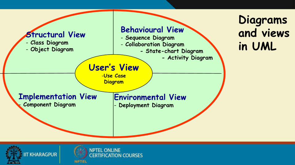
User’s View-Use CaseDiagram
Structural View- Class Diagram- Object Diagram
Implementation View- Component Diagram
Environmental View- Deployment Diagram
Behavioural View- Sequence Diagram- Collaboration Diagram
- State-chart Diagram- Activity Diagram
Diagrams and views in UML
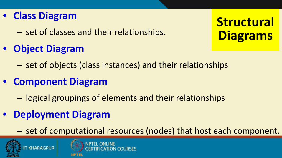
Structural Diagrams
• Class Diagram– set of classes and their relationships.
• Object Diagram– set of objects (class instances) and their relationships
• Component Diagram– logical groupings of elements and their relationships
• Deployment Diagram– set of computational resources (nodes) that host each component.

Behavioral Diagrams
• Use Case Diagram– high-level behaviors of the system, user
goals, external entities: actors• Sequence Diagram
– focus on time ordering of messages• Collaboration Diagram
– focus on structural organization of objects and messages
• State Chart Diagram– event driven state changes of system
• Activity Diagram– flow of control between activities
Some Insights on Using UML
• “UML is a large and growing beast, but you don’t need all of it in every problem you solve…”– Martin Fowler
• “…when learning the UML, you need to be aware that certain constructs and notations are only helpful in detailed design while others are useful in requirements analysis …” Brian Henderson-Sellers
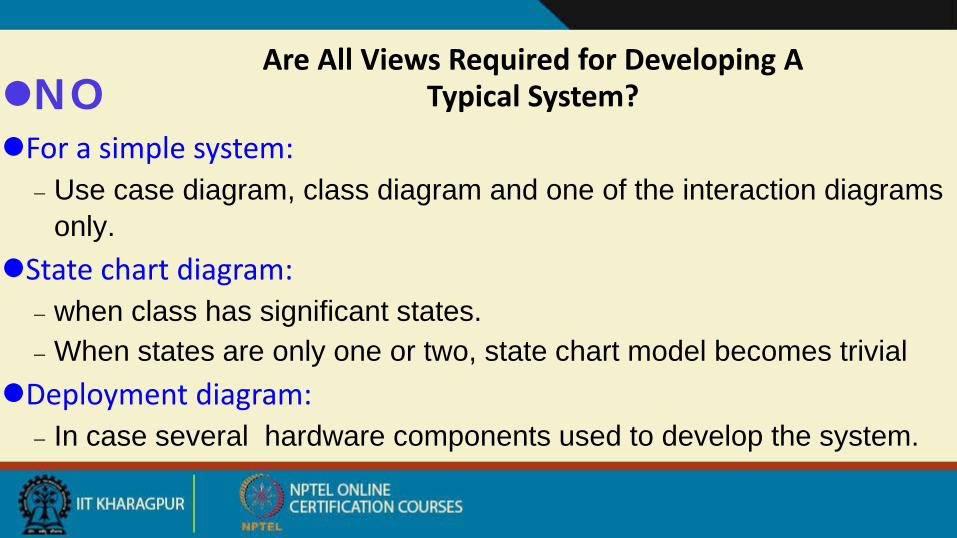
NOFor a simple system:
− Use case diagram, class diagram and one of the interaction diagrams only.
State chart diagram:− when class has significant states.− When states are only one or two, state chart model becomes trivial
Deployment diagram:− In case several hardware components used to develop the system.
Are All Views Required for Developing A Typical System?
9/6/2018
Use Case Modelling
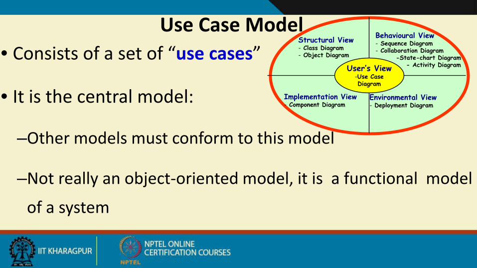
Use Case Model • Consists of a set of “use cases”
• It is the central model:
–Other models must conform to this model
–Not really an object-oriented model, it is a functional model
of a system
User’s View-Use CaseDiagram
Structural View- Class Diagram- Object Diagram
Implementation View- Component Diagram
Environmental View- Deployment Diagram
Behavioural View- Sequence Diagram- Collaboration Diagram
-State-chart Diagram- Activity Diagram

A Use Case • A case of use: A way in which a system can be used by the
users to achieve specific goals
• Corresponds to a high-level requirement.
• Defines external behavior without revealing internal structure of system
• Set of related scenarios tied together by a common goal.
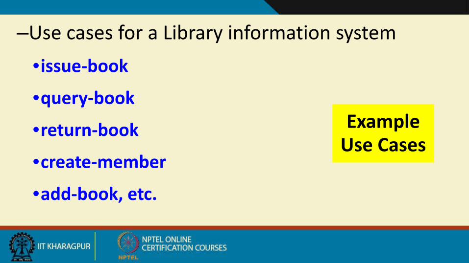
Example Use Cases
–Use cases for a Library information system•issue-book
•query-book
•return-book
•create-member
•add-book, etc.
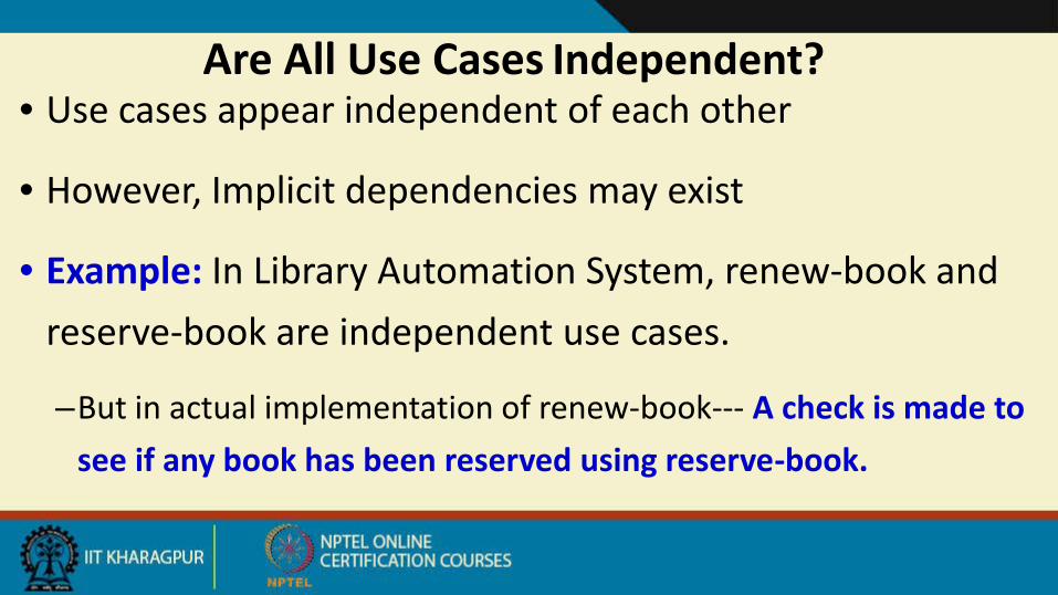
Are All Use Cases Independent?• Use cases appear independent of each other
• However, Implicit dependencies may exist
• Example: In Library Automation System, renew-book and reserve-book are independent use cases.
–But in actual implementation of renew-book--- A check is made to see if any book has been reserved using reserve-book.
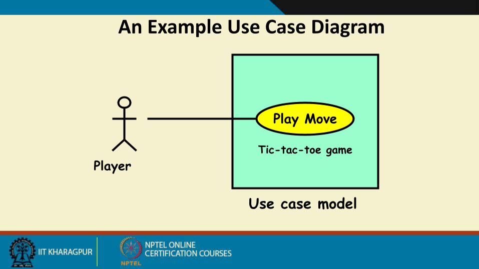
An Example Use Case Diagram
Use case model
Tic-tac-toe game
Play Move
Player
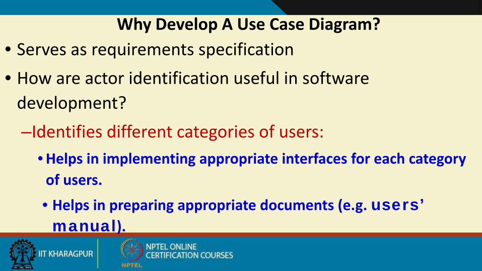
Why Develop A Use Case Diagram?• Serves as requirements specification• How are actor identification useful in software
development?–Identifies different categories of users:
• Helps in implementing appropriate interfaces for each category of users.• Helps in preparing appropriate documents (e.g. users’ manual).
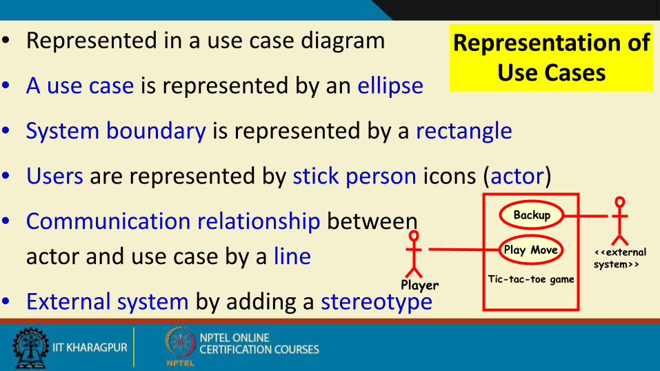
Representation of Use Cases
• Represented in a use case diagram
• A use case is represented by an ellipse
• System boundary is represented by a rectangle
• Users are represented by stick person icons (actor)
• Communication relationship between actor and use case by a line
• External system by adding a stereotypeTic-tac-toe game
Play Move
Player
Backup
<<external system>>
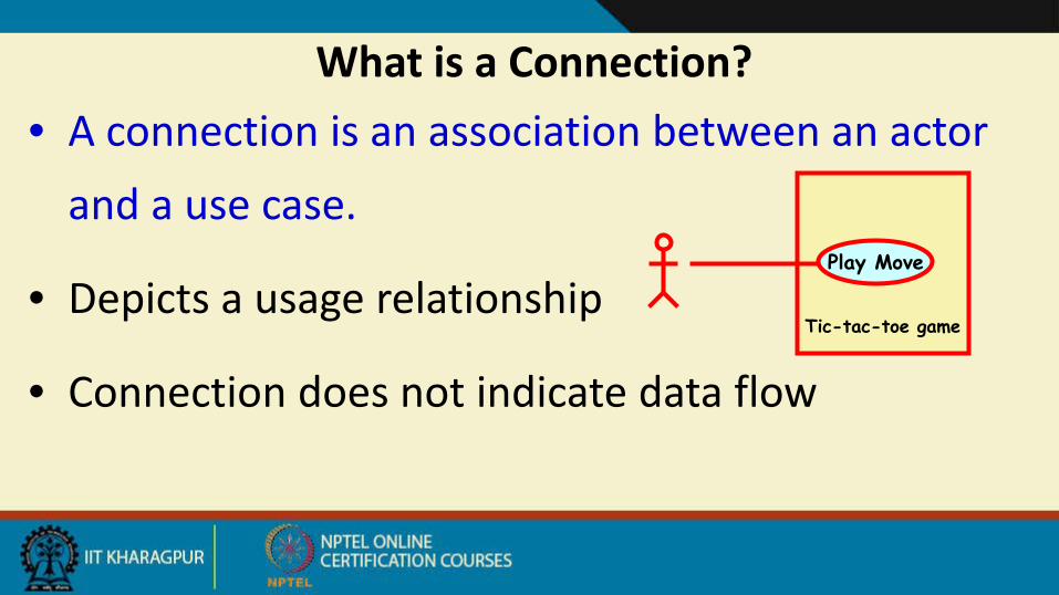
What is a Connection?• A connection is an association between an actor
and a use case.
• Depicts a usage relationship
• Connection does not indicate data flowTic-tac-toe game
Play Move

Relationships between Use Cases and Actors
• Association relation indicates that the actor and the corresponding use case communicate with one another.
updategrades
faculty

Another Example Use Case Diagram
Rent Videos
. . .
Video Store Information System
<<external system>>Credit Authorization
Service
Clerk
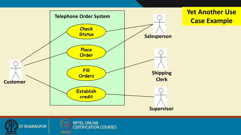
Yet Another Use Case Example
Check Status
Place Order
Fill Orders
Establish credit
Customer
Salesperson
Shipping Clerk
Supervisor
Telephone Order System

Factoring Use Cases• Two main reasons for factoring:
–Complex use cases need to be factored into simpler use cases
–Helps represent common behavior across different use cases
• Three ways of factoring:
–Generalization
–Include
–Extend

Generalization• The child use case inherits the
behavior of the parent use case.
–The child may add to or override some of the behavior of its parent.
parent
child
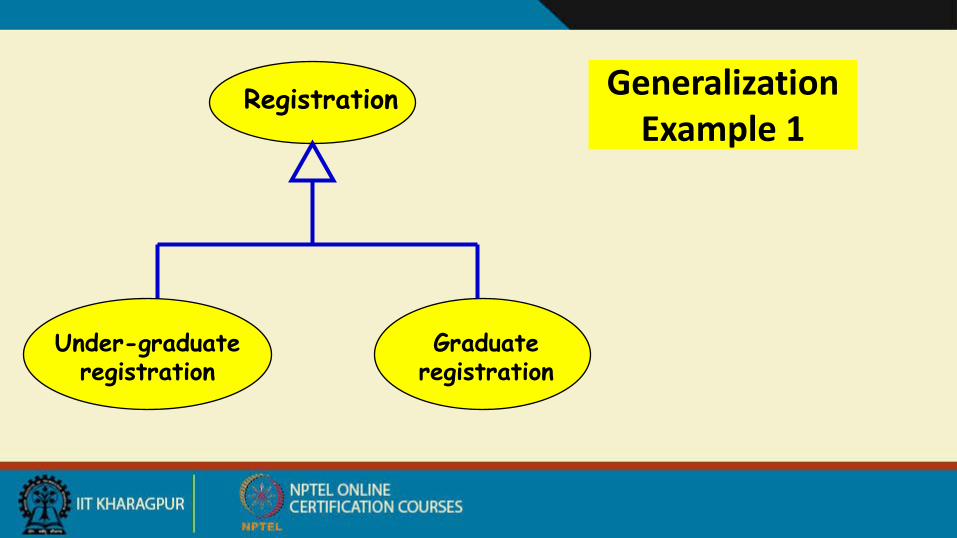
Registration
Graduateregistration
Under-graduateregistration
Generalization Example 1

Factoring Use Cases Using Generalization
Pay membership fee
Pay through library pay cardPay through credit card
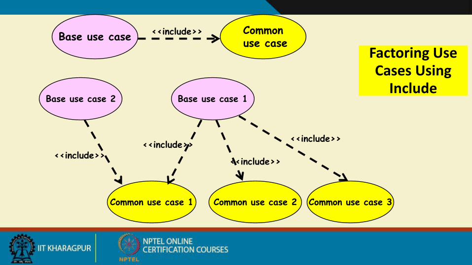
Factoring Use Cases Using
Include
Base use case Commonuse case
<<include>>
Base use case 2
Common use case 3Common use case 2Common use case 1
Base use case 1
<<include>><<include>>
<<include>>
<<include>>

Example of Factoring Use Cases Using
Include
Issue Book
Check Reservation
Renew Book
<<include>><<include>>
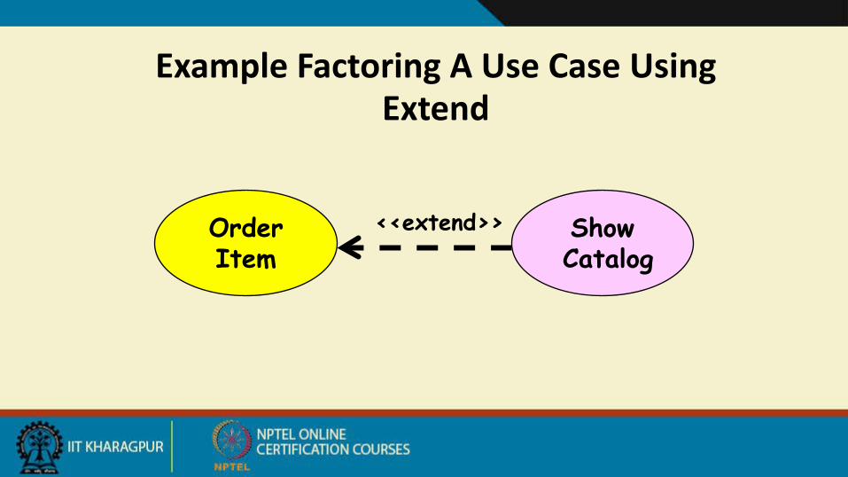
Example Factoring A Use Case Using Extend
OrderItem
ShowCatalog
<<extend>>

Extension Point• The base use case may include/extend other use cases:
– At certain points, called extension points.
• Note the direction of the arrow
Perform SaleAfter checkout
Gift wrap Product
<<extend>>Product is a gift

Use Case Relationships
Place Order
Supply Customer Data
Order Product
Arrange Payment
Request Catalog
<<include>>
<<include>><<include>>
<<extend>>Salesperson asks for catalog
Sales Person
Cash Payment
Credit Payment
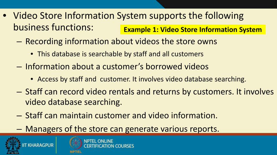
Example 1: Video Store Information System
• Video Store Information System supports the following business functions: – Recording information about videos the store owns
• This database is searchable by staff and all customers
– Information about a customer’s borrowed videos• Access by staff and customer. It involves video database searching.
– Staff can record video rentals and returns by customers. It involves video database searching.
– Staff can maintain customer and video information. – Managers of the store can generate various reports.
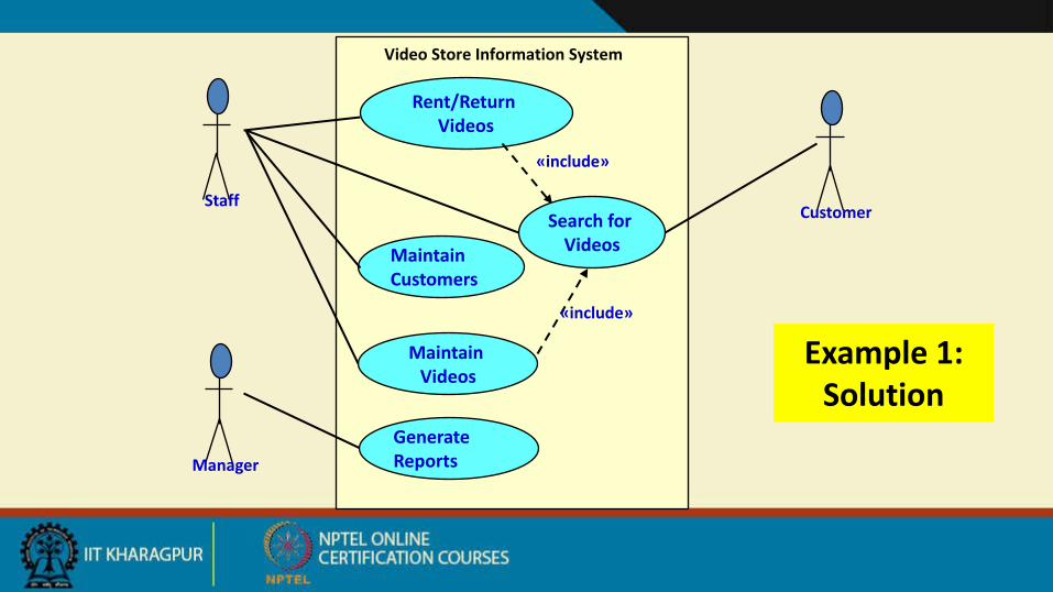
Example 1: Solution
Maintain Customers
Staff
Rent/Return Videos
Maintain Videos
Generate Reports
Customer
Manager
Search for Videos
«include»
«include»
Video Store Information System

Use Case Description
NameActors
PreconditionsPost conditions
Mainline Scenario
Alternatives flows
Alistair Cockburn “Writing Effective Use Cases”
Trigger
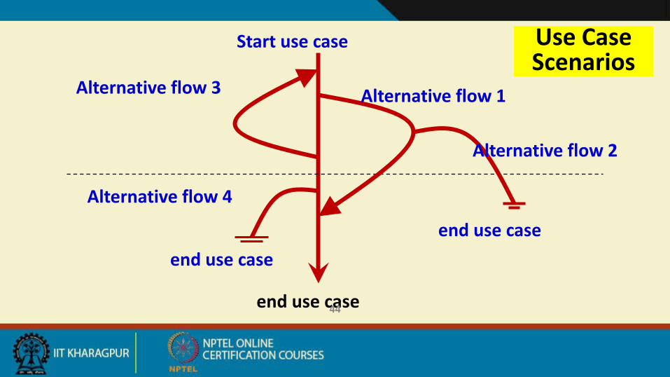
Use Case Scenarios
Start use case
Alternative flow 3 Alternative flow 1
Alternative flow 2
Alternative flow 4
end use case
end use caseend use case
44
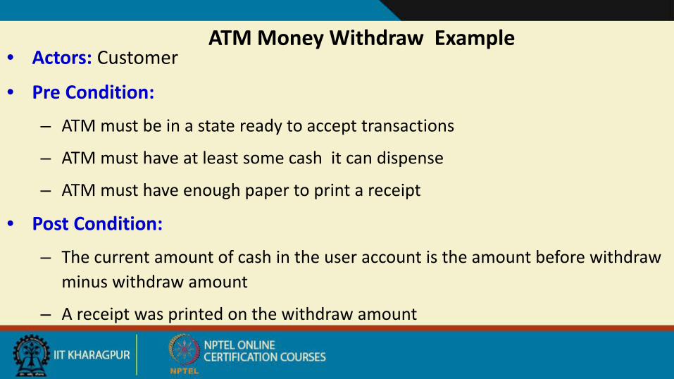
ATM Money Withdraw Example• Actors: Customer
• Pre Condition:
– ATM must be in a state ready to accept transactions
– ATM must have at least some cash it can dispense
– ATM must have enough paper to print a receipt
• Post Condition:
– The current amount of cash in the user account is the amount before withdraw minus withdraw amount
– A receipt was printed on the withdraw amount
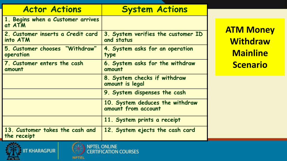
ATM Money Withdraw Mainline Scenario
Actor Actions System Actions1. Begins when a Customer arrives at ATM2. Customer inserts a Credit card into ATM
3. System verifies the customer ID and status
5. Customer chooses “Withdraw” operation
4. System asks for an operation type
7. Customer enters the cash amount
6. System asks for the withdraw amount8. System checks if withdraw amount is legal9. System dispenses the cash
10. System deduces the withdraw amount from account
11. System prints a receipt
13. Customer takes the cash and the receipt
12. System ejects the cash card
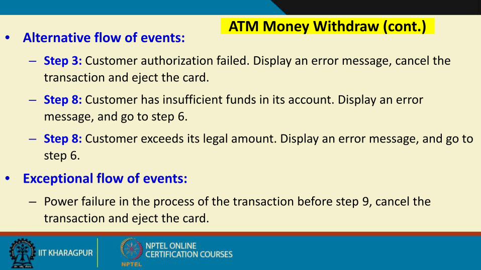
ATM Money Withdraw (cont.)• Alternative flow of events:
– Step 3: Customer authorization failed. Display an error message, cancel the transaction and eject the card.
– Step 8: Customer has insufficient funds in its account. Display an error message, and go to step 6.
– Step 8: Customer exceeds its legal amount. Display an error message, and go to step 6.
• Exceptional flow of events:– Power failure in the process of the transaction before step 9, cancel the
transaction and eject the card.
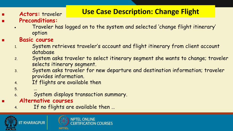
Use Case Description: Change Flight Actors: traveler Preconditions:
• Traveler has logged on to the system and selected ‘change flight itinerary’ option
Basic course1. System retrieves traveler’s account and flight itinerary from client account
database2. System asks traveler to select itinerary segment she wants to change; traveler
selects itinerary segment.3. System asks traveler for new departure and destination information; traveler
provides information.4. If flights are available then5. …6. System displays transaction summary.
Alternative courses4. If no flights are available then …
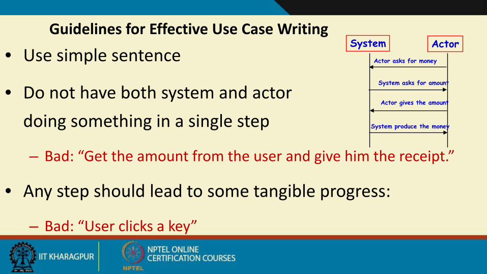
Guidelines for Effective Use Case Writing
• Use simple sentence
• Do not have both system and actor doing something in a single step
– Bad: “Get the amount from the user and give him the receipt.”
• Any step should lead to some tangible progress:
– Bad: “User clicks a key”
System ActorActor asks for money
System asks for amount
Actor gives the amount
System produce the money

Identification of Use Cases1. Actor-based:
- Identify the actors related to a system or organization.
- For each actor, identify the processes they initiate or participate in.
2. Event-based
- Identify the external events that the system must respond to.
- Relate the events to actors and use cases.
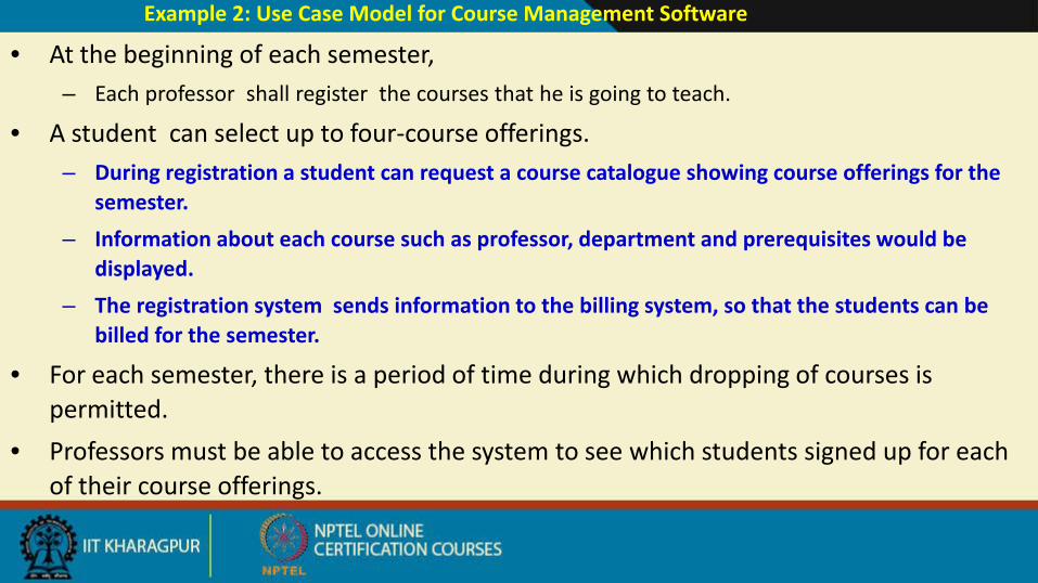
Example 2: Use Case Model for Course Management Software
• At the beginning of each semester,– Each professor shall register the courses that he is going to teach.
• A student can select up to four-course offerings.– During registration a student can request a course catalogue showing course offerings for the
semester. – Information about each course such as professor, department and prerequisites would be
displayed. – The registration system sends information to the billing system, so that the students can be
billed for the semester.
• For each semester, there is a period of time during which dropping of courses is permitted.
• Professors must be able to access the system to see which students signed up for each of their course offerings.
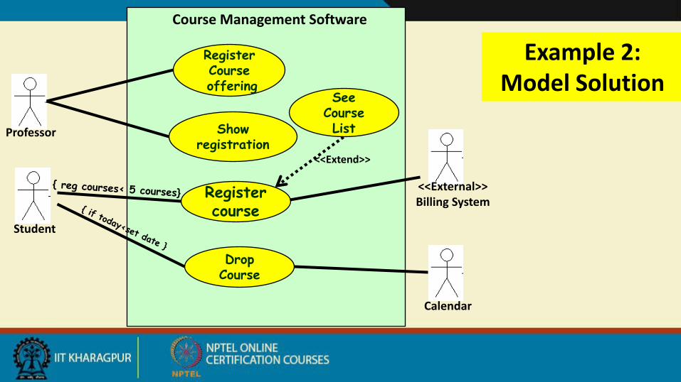
RegisterCourseoffering
Show registration
Register course
Drop Course
Student
Calendar
Course Management Software
Example 2: Model Solution
See Course ListProfessor
<<Extend>>
<<External>>Billing System
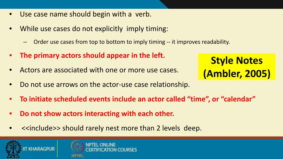
Style Notes (Ambler, 2005)
• Use case name should begin with a verb.
• While use cases do not explicitly imply timing:
– Order use cases from top to bottom to imply timing -- it improves readability.
• The primary actors should appear in the left.
• Actors are associated with one or more use cases.
• Do not use arrows on the actor-use case relationship.
• To initiate scheduled events include an actor called “time”, or “calendar”
• Do not show actors interacting with each other.
• <<include>> should rarely nest more than 2 levels deep.
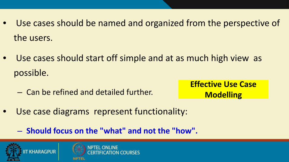
Effective Use Case Modelling
• Use cases should be named and organized from the perspective of the users.
• Use cases should start off simple and at as much high view as possible.
– Can be refined and detailed further.
• Use case diagrams represent functionality:
– Should focus on the "what" and not the "how".
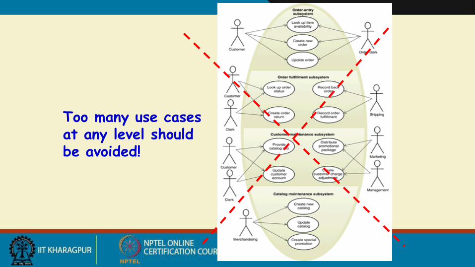
Too many use cases at any level should be avoided!

Use Case Packaging
Query balance
Receivegrant
Print Balance sheet
Make payments
Accounts
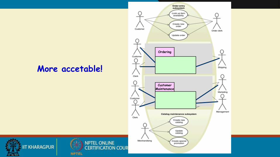
More accetable!Query balance
Ordering
Query balance
CustomerMaintenance
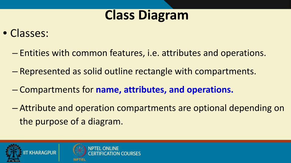
Class Diagram• Classes:
– Entities with common features, i.e. attributes and operations.
– Represented as solid outline rectangle with compartments.
– Compartments for name, attributes, and operations.
– Attribute and operation compartments are optional depending on the purpose of a diagram.
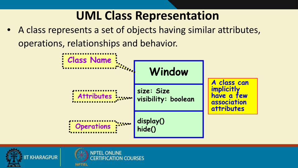
UML Class Representation• A class represents a set of objects having similar attributes,
operations, relationships and behavior.
Windowsize: Sizevisibility: boolean
display()hide()
Class Name
Attributes
Operations
A class can implicitly have a few association attributes
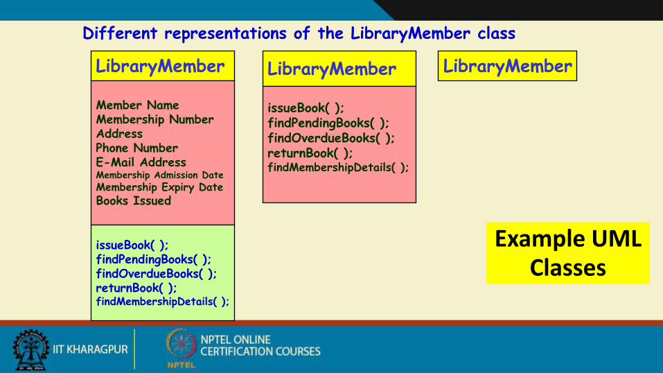
Example UML Classes
Different representations of the LibraryMember class
LibraryMember
Member NameMembership NumberAddressPhone NumberE-Mail AddressMembership Admission DateMembership Expiry DateBooks Issued
issueBook( );findPendingBooks( );findOverdueBooks( );returnBook( );findMembershipDetails( );
LibraryMember
issueBook( );findPendingBooks( );findOverdueBooks( );returnBook( );findMembershipDetails( );
LibraryMember

What are the Different Types of Relationships Among Classes?
• Four types of relationships:
– Inheritance
– Association
– Aggregation/Composition
– Dependency
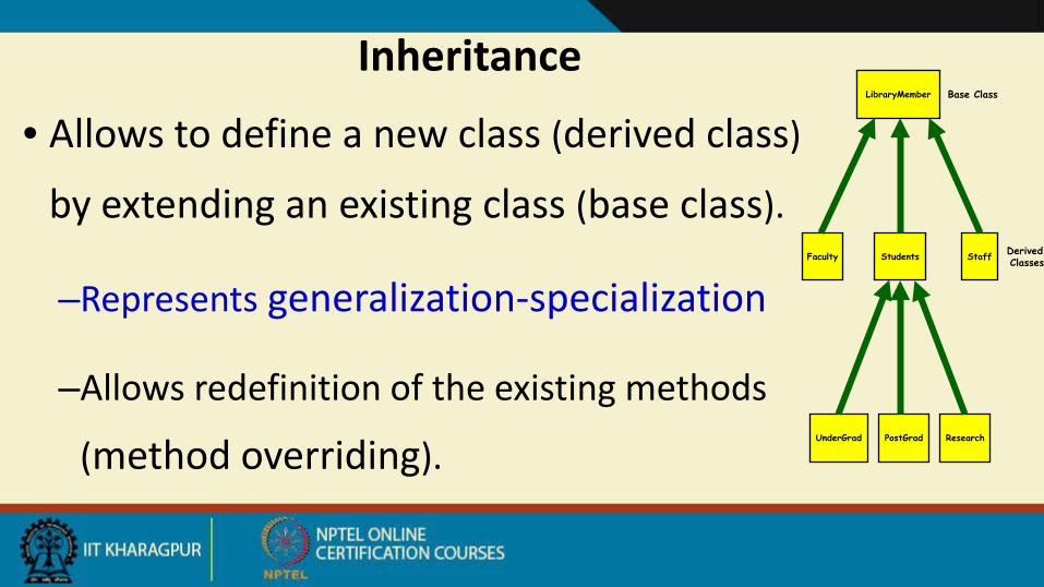
• Allows to define a new class (derived class)
by extending an existing class (base class).
–Represents generalization-specialization
–Allows redefinition of the existing methods
(method overriding).
InheritanceLibraryMember
ResearchPostGradUnderGrad
StaffStudentsFaculty
Base Class
DerivedClasses
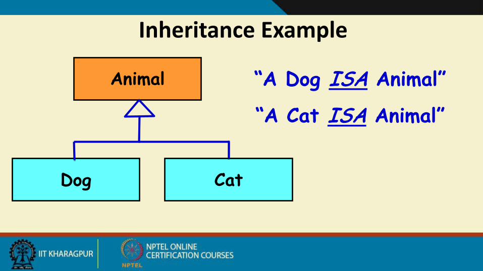
Inheritance Example
“A Dog ISA Animal”Animal
Dog Cat
“A Cat ISA Animal”
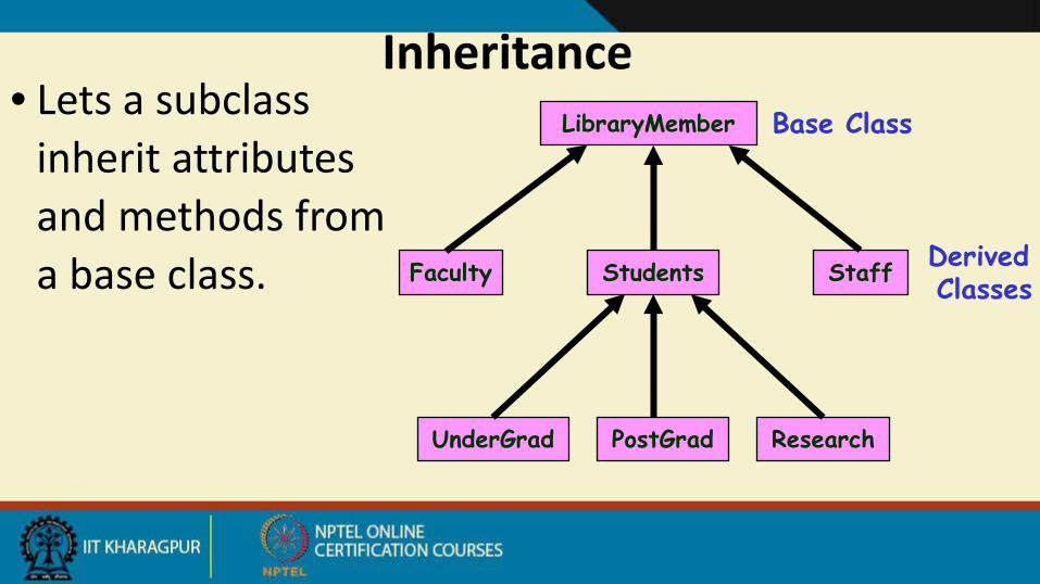
• Lets a subclass inherit attributes and methods from a base class.
InheritanceLibraryMember
ResearchPostGradUnderGrad
StaffStudentsFaculty
Base Class
DerivedClasses
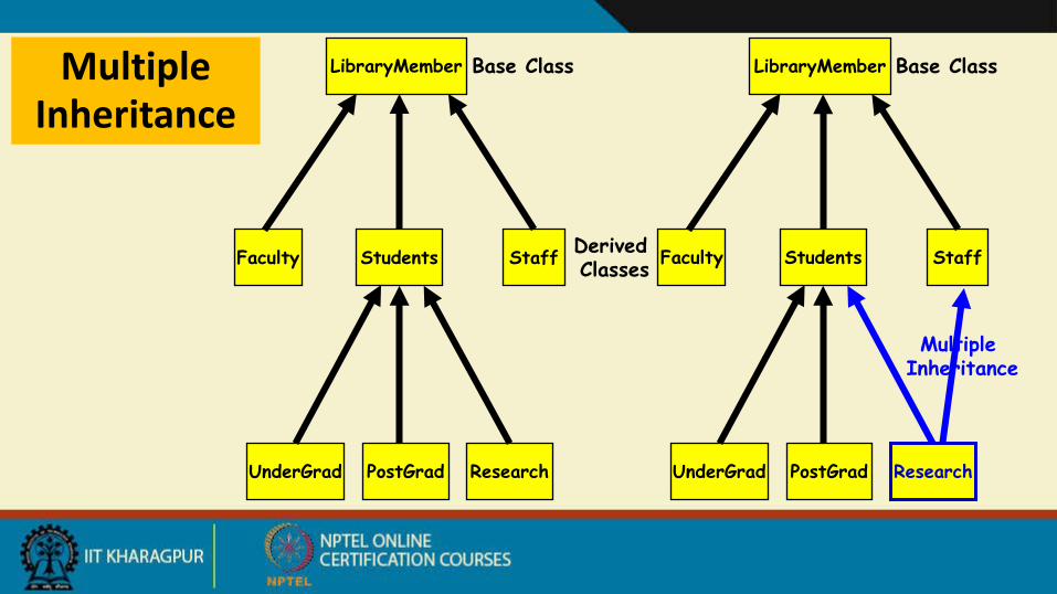
Multiple Inheritance
LibraryMember
ResearchPostGradUnderGrad
StaffStudentsFaculty
Base Class
DerivedClasses
LibraryMember
ResearchPostGradUnderGrad
StaffStudentsFaculty
Base Class
Multiple Inheritance
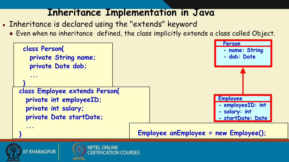
Inheritance Implementation in JavaInheritance is declared using the "extends" keyword
Even when no inheritance defined, the class implicitly extends a class called Object.Person- name: String - dob: Date
Employee- employeeID: int- salary: int- startDate: Date
class Person{private String name;private Date dob;...
}class Employee extends Person{
private int employeeID;private int salary;private Date startDate;...
} Employee anEmployee = new Employee();
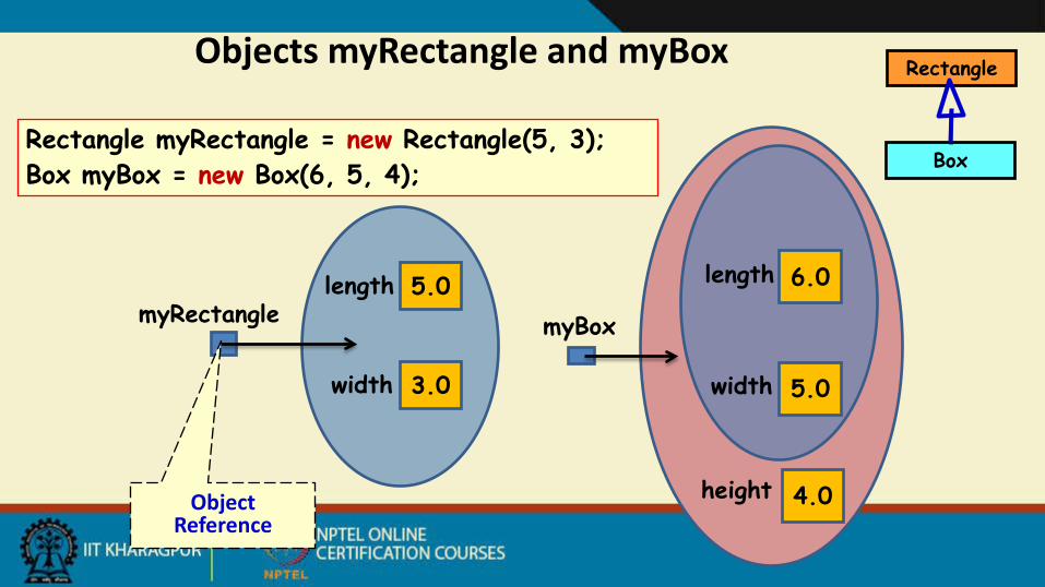
Rectangle myRectangle = new Rectangle(5, 3);Box myBox = new Box(6, 5, 4);
Objects myRectangle and myBox
5.0
3.0
length
width
myRectangle6.0
5.0
length
width
4.0height
myBox
Object Reference
Rectangle
Box
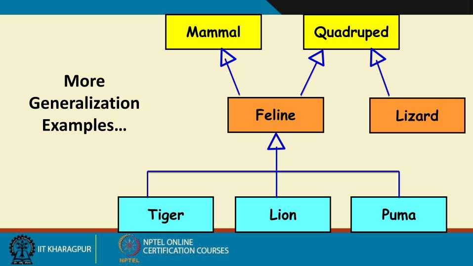
More Generalization
Examples…
Mammal Quadruped
Feline Lizard
Tiger Lion Puma
69
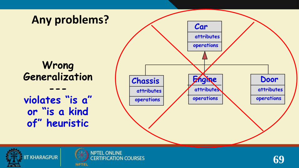
Wrong Generalization
---violates “is a” or “is a kind of” heuristic
Carattributesoperations
Chassisattributesoperations
Engineattributesoperations
Doorattributesoperations
Any problems?

Inheritance Example LibraryBook
Discriminator: allows one to group subclasses into clusters that correspond to a semantic category.
IssuableSingle Volume
Book
IssuableBookSet
ReferenceSingle Volume
Book
ReferenceBookSet
issuable reference

Inheritance Pitfalls• Inheritance certainly promotes reuse.
• Indiscriminate use can result in poor quality programs.
• Base class attributes and methods visible in derived class…
– Leads to tight coupling
Association Relationship• How implemented in program?
• Enables objects to communicate with each other:–One object must “know” the ID of the corresponding
object in the association.
• Usually binary:–But in general can be n-ary.
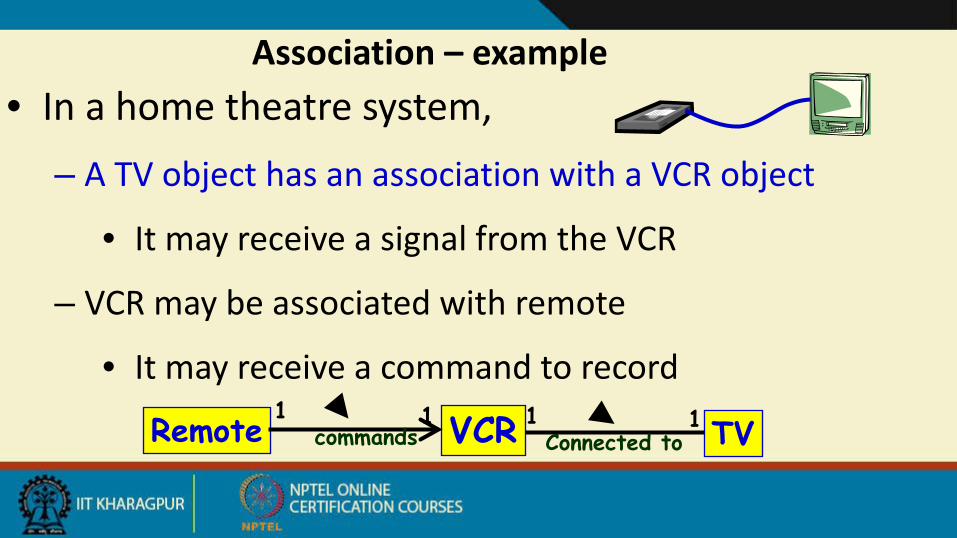
Association – example • In a home theatre system,
– A TV object has an association with a VCR object
• It may receive a signal from the VCR
– VCR may be associated with remote
• It may receive a command to record
VCR TV1Connected to
1Remote 1commands
1
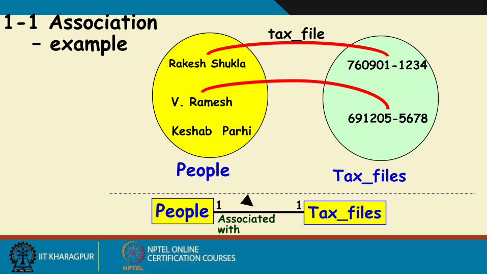
Rakesh Shukla
V. Ramesh
760901-1234
691205-5678
People Tax_files
tax_file1-1 Association – example
People Tax_files1 1Associated with
Keshab Parhi
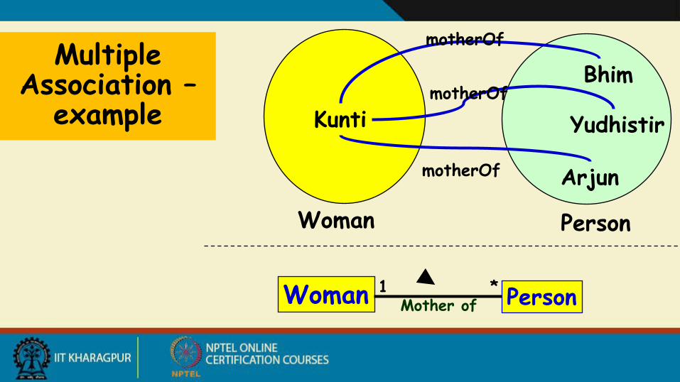
Kunti
Bhim
Arjun
Woman Person
motherOfMultiple Association –
example
motherOf
YudhistirmotherOf
Woman Person1 *Mother of
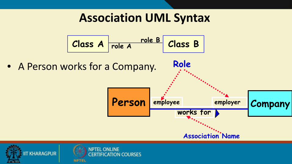
works for
Association UML Syntax
• A Person works for a Company.
Person Companyemployee employer
Association Name
Role
Class A Class Brole Arole B
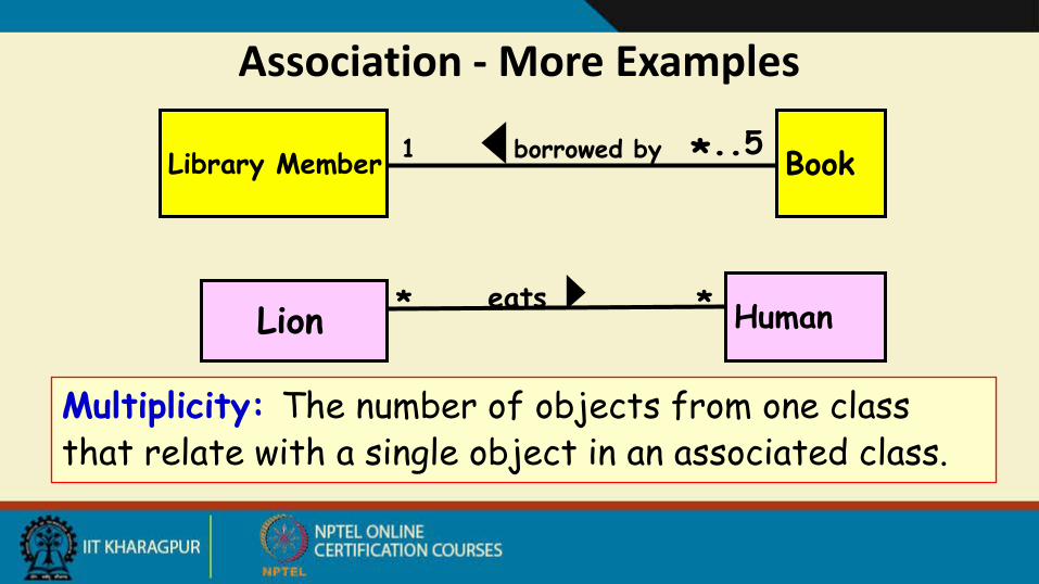
Association - More Examples
Library Member Book1 *..5borrowed by
Lion Human** eats
Multiplicity: The number of objects from one class that relate with a single object in an associated class.
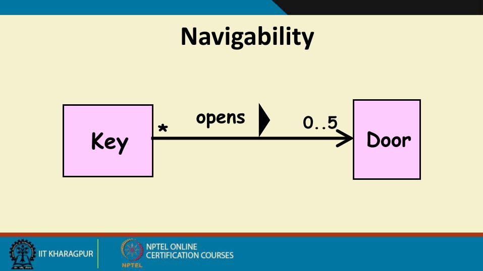
Navigability
Key Door0..5*
opens

• A teacher teaches 1 to 3 courses (subjects)• Each course is taught by only one teacher. • A student can take between 1 to 5 courses. • A course can have 10 to 300 students.
Association – Multiplicity
Teacher Courseteaches 1..31
Students takes
1..5
10..300
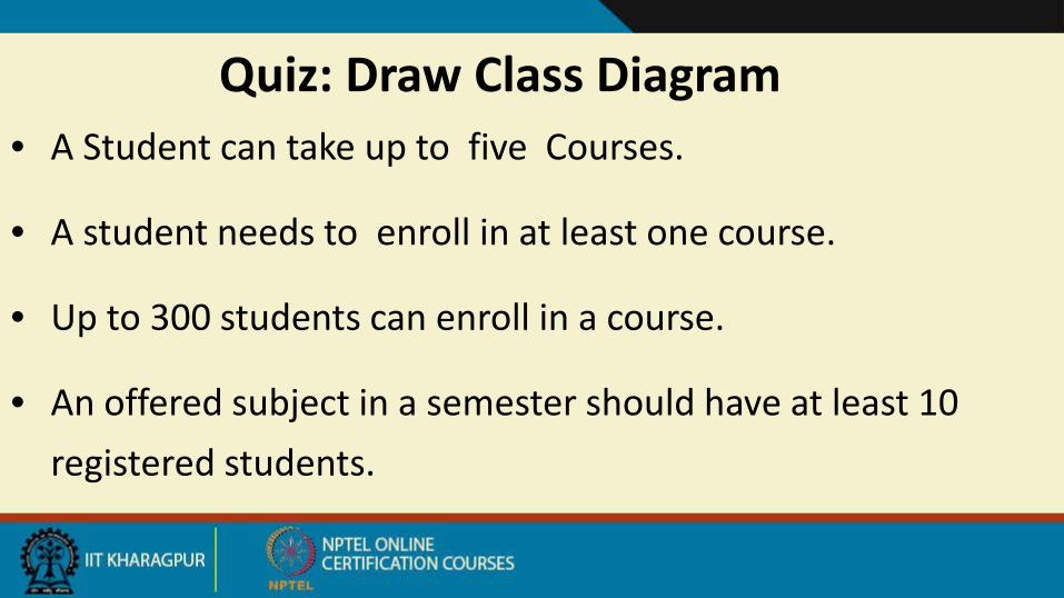
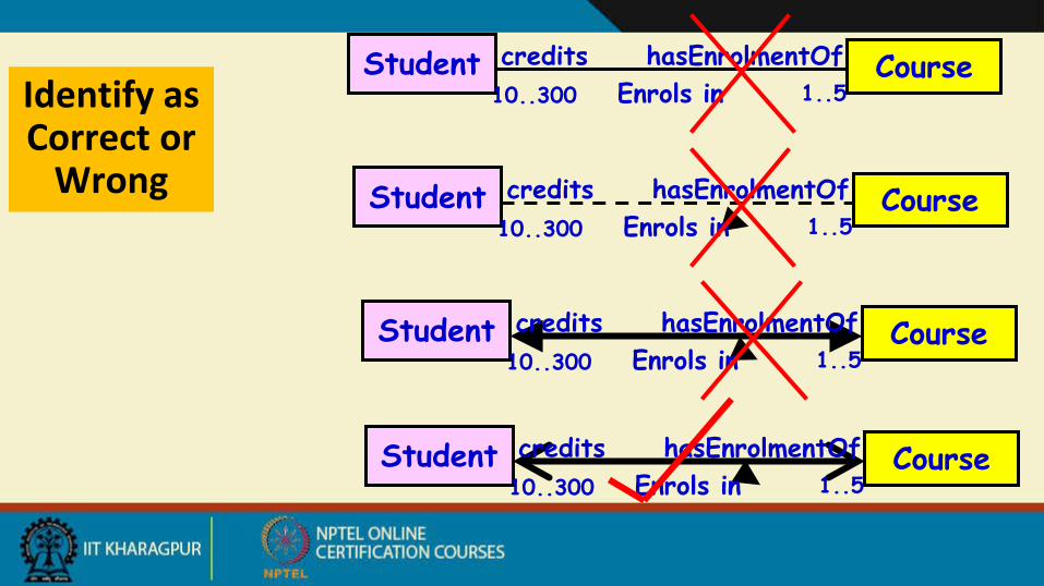
Quiz: Draw Class Diagram• A Student can take up to five Courses.
• A student needs to enroll in at least one course.
• Up to 300 students can enroll in a course.
• An offered subject in a semester should have at least 10 registered students.
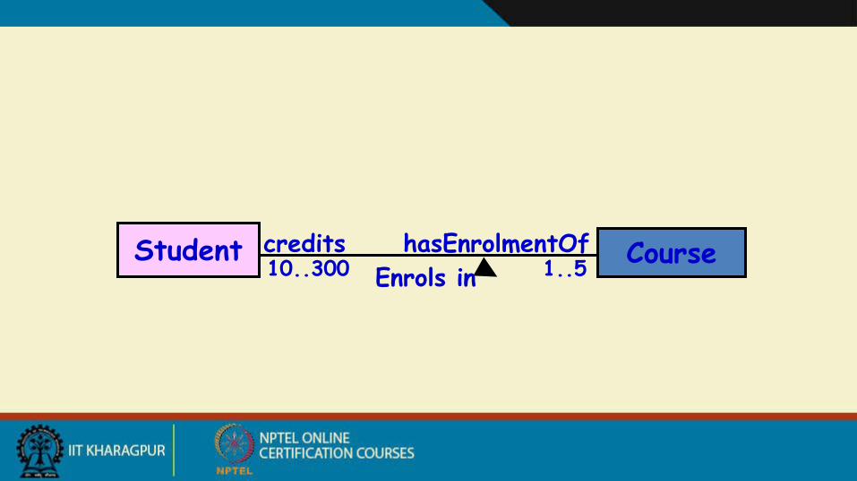
Student Coursecredits10..300 1..5
hasEnrolmentOfEnrols in
Student Coursecredits10..300 1..5
hasEnrolmentOfEnrols in
Student Coursecredits10..300 1..5
hasEnrolmentOfEnrols in
Student Coursecredits10..300 1..5
hasEnrolmentOfEnrols in
Student Coursecredits10..300 1..5
hasEnrolmentOfEnrols in
Identify as Correct or
Wrong
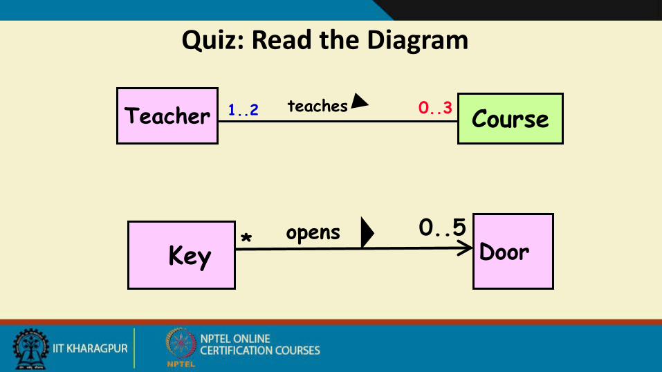
Quiz: Read the Diagram
Teacher Courseteaches 0..31..2
Key Door0..5* opens
Association and Link• A link:
– An instance of an association– Exists between two or more objects– Dynamically created and destroyed as the run of a
system proceeds• For example:
– An employee joins an organization. – Leaves that organization and joins a new organization.