Embed Size (px)
Citation preview
Report in Support of an Assessment of Effects on the Environment
Report'in'Support'of'an'Assessment'of'Effects'on'the$Environment!
Navigational*Risk*Assessment*of*Engineered!Channel'Designs!
!!!
Prepared!for!Chancery!Green!on!behalf!of!Refining!NZ!by!
Navigatus!Consulting!!
Post!Consultation!Report!Rev!0!
15!August!2017!

This page is intentionally left blank
Navigational Risk Assessment of Engineered Channel Designs Navigatus
Navigational Risk Assessment of Environmental Effects Report Rev 0 dated 15 Aug 17.docx
Prepared by Navigatus Consulting Ltd for:
Chancery Green on behalf of Refining NZ
Navigatus Consulting Limited
Level 2, 347 Parnell Road
PO Box 137249
Parnell, Auckland 1052
+64 9 377 4132
www.navigatusconsulting.com
Quality Control
Prepared by: Paul Dickinson (Navigatus Consulting)
Reviewed by: Geraint Bermingham (Navigatus Consulting)
Revision Date Authorised By
Name Signature
Draft A 11 October 2016 G. Bermingham
Draft B 1 November 2016 G. Bermingham
Draft for Client review
2 November 2016 G. Bermingham
Revised Draft 2 December 2106 G. Bermingham
Public Consultation Draft
14 December 2016 G. Bermingham p.p.
Post Consultation Report Rev 0
Improved explanations in places.
Includes consideration of navigational effect of disposal areas
15 August 2017 G. Bermingham

Navigatus Navigational Risk Assessment of Engineered Channel Designs
i
This page is intentionally left blank
Navigational Risk Assessment of Engineered Channel Designs Navigatus
ii Navigational Risk Assessment of Environmental Effects Report Rev 0 dated 15 Aug 17.docx
Table of Contents
1.! Executive Summary ................................................................................. 1!
2.! Introduction .............................................................................................. 3!
3.! Risk Assessment Process ......................................................................... 5!
4.! Context ..................................................................................................... 6!
4.1.! Navigational Area Considered ................................................................................ 6!4.2.! Port/Pilotage Operation ......................................................................................... 12!4.3.! Ship Navigation Paths ........................................................................................... 12!4.4.! Types of Ships Considered ................................................................................... 12!4.5.! Number of Ship Visits ............................................................................................ 13!4.6.! Probability and Potential Causes of Grounding .................................................... 13!4.7.! Typical Oil Tanker Operation ................................................................................ 14!
5.! Risk Analysis ........................................................................................... 15!
5.1.! Undesirable Event ................................................................................................. 15!5.2.! Operational Considerations ................................................................................... 15!5.3.! Channel Considerations ........................................................................................ 16!5.4.! Detailed Reach Analysis – Existing Channel ........................................................ 18!5.5.! Comparative Analysis ........................................................................................... 23!5.6.! Consequences ...................................................................................................... 27!5.7.! Impact of dredged material disposal sites. ............................................................ 30!
6.! Findings ................................................................................................... 31!
6.1.! Risk Factors .......................................................................................................... 31!6.2.! Risk Profile - Channels .......................................................................................... 32!6.3.! Overall Risk Assessment - Channels .................................................................... 36!6.4.! Risk Assessment – Disposal Sites ........................................................................ 37!
7.! Conclusions ............................................................................................ 38!
7.1.! Channel Design – Relative Risk ............................................................................ 38!7.2.! Disposal Sites – Absolute Risk ............................................................................. 38!

Navigatus Navigational Risk Assessment of Engineered Channel Designs
iii
This page is intentionally left blank
Navigational Risk Assessment of Engineered Channel Designs Navigatus
iv Navigational Risk Assessment of Environmental Effects Report Rev 0 dated 15 Aug 17.docx
Glossary
Term Meaning
Aft Towards the stern, or back, of a ship.
Aframax Tanker A medium-sized crude oil tanker with a dead weight tonnage between 80,000 and 120,000.
ALARP As Low As Reasonably Practicable. An internationally recognised term used within the context of managing risk.
Bow The forward part of a ship.
Breasting Dolphin A man made structure that extends above the water level that is not connected to shore, against which a ship may berth.
Chart A nautical map showing the maritime area including depths, navigation marks and selected tidal current flows.
Chart plotter An electronic device that displays a chart and superimposes the GPS-derived position of a ship. The device can also display data such as ship speed and course.
Conn To direct the steerage of a ship. An office performing this duty is said to ‘have the conn’.
Currency
The extent to which an individual is recently practiced in undertaking an operation and up to date with procedures. Often to be considered ‘current’ an individual is expected to have carried out the procedure within a specified time period.
Deadweight Tonnage
A measure of how much weight a ship is carrying or can safely carry. It is the sum of the weights of cargo, fuel, fresh water, ballast water, provisions, passengers and crew.
Displacement A measure of the weight of a ship. The displacement is the weight of the body of water that would otherwise be occupied by a ship.
Fore Towards the bow, or front, of a ship.
Forepeak The part of the hold of a ship within the angle of the bow.
Freeboard The height of a ship’s side between the actual waterline and the deck.
Grounding The act of a ship coming into firm contact with the bed of the sea.
Heading A direction or bearing.
Headway The forward progress made by a vessel.
Human Factors The factors that influence human performance in a given operational environment and situation.
Navigatus Navigational Risk Assessment of Engineered Channel Designs
v
Term Meaning
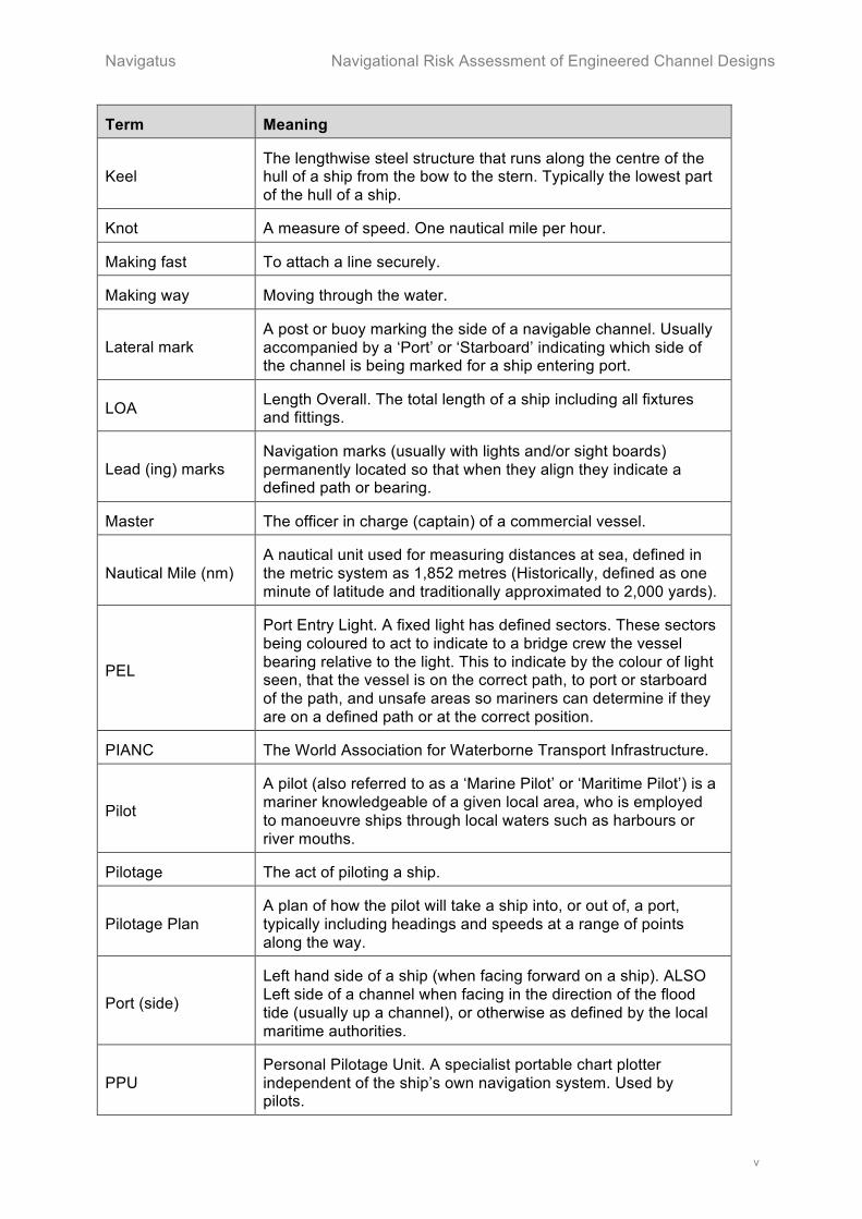
Keel The lengthwise steel structure that runs along the centre of the hull of a ship from the bow to the stern. Typically the lowest part of the hull of a ship.
Knot A measure of speed. One nautical mile per hour.
Making fast To attach a line securely.
Making way Moving through the water.
Lateral mark A post or buoy marking the side of a navigable channel. Usually accompanied by a ‘Port’ or ‘Starboard’ indicating which side of the channel is being marked for a ship entering port.
LOA Length Overall. The total length of a ship including all fixtures and fittings.
Lead (ing) marks Navigation marks (usually with lights and/or sight boards) permanently located so that when they align they indicate a defined path or bearing.
Master The officer in charge (captain) of a commercial vessel.
Nautical Mile (nm) A nautical unit used for measuring distances at sea, defined in the metric system as 1,852 metres (Historically, defined as one minute of latitude and traditionally approximated to 2,000 yards).
PEL
Port Entry Light. A fixed light has defined sectors. These sectors being coloured to act to indicate to a bridge crew the vessel bearing relative to the light. This to indicate by the colour of light seen, that the vessel is on the correct path, to port or starboard of the path, and unsafe areas so mariners can determine if they are on a defined path or at the correct position.
PIANC The World Association for Waterborne Transport Infrastructure.
Pilot
A pilot (also referred to as a ‘Marine Pilot’ or ‘Maritime Pilot’) is a mariner knowledgeable of a given local area, who is employed to manoeuvre ships through local waters such as harbours or river mouths.
Pilotage The act of piloting a ship.
Pilotage Plan A plan of how the pilot will take a ship into, or out of, a port, typically including headings and speeds at a range of points along the way.
Port (side)
Left hand side of a ship (when facing forward on a ship). ALSO Left side of a channel when facing in the direction of the flood tide (usually up a channel), or otherwise as defined by the local maritime authorities.
PPU Personal Pilotage Unit. A specialist portable chart plotter independent of the ship’s own navigation system. Used by pilots.

Navigational Risk Assessment of Engineered Channel Designs Navigatus
vi Navigational Risk Assessment of Environmental Effects Report Rev 0 dated 15 Aug 17.docx
Term Meaning
Reach A defined open or straight portion of water or channel.
Starboard (side)
Right hand side of a ship (when facing forward on a ship). ALSO Right side of a channel when facing in the direction of the flood tide (usually up a channel), or otherwise as defined by the local maritime authorities.
SOPs Standard Operating Procedures
Stern Back or rear end of a ship.
Steerage Effective directional control of the ship by means of the action of water over the rudder.
Suezmax Tanker A crude oil tanker, which is the maximum size that can transit the Suez Canal. Typical dead weight tonnage is between 120,000 and 200,000.
Waterline The level of the water on the side of a ship. Or, the designed line that the water will be at with the ship in a known condition.
Way As in “taking way off”. See Headway and Making way.
Windage The effect of the wind on the surface of a ship (hull and superstructure) above the water line.

Navigatus Navigational Risk Assessment of Engineered Channel Designs
1
1. Executive Summary
Context
The nature and depth of the approach and channel to the Marsden Point refinery currently limits visiting oil tankers by draught. This allows for fully laden Aframax tankers, but only partly laden Suezmax tankers. It is proposed to dredge and realign the channel to allow for fully laden Suezmax tanker operations. Two possible channel designs labelled ‘Option 2’ and ‘Option 4.2’ had been shortlisted for consideration in this risk assessment.
Scope and Process
This risk assessment considers the risks associated with fully laden Suezmax tanker operations (that is vessels in deep draught) to and from the Marsden Point refinery jetty. Given that each harbour and port is unique, and so incident information from one is not directly applicable to another, a quantitative risk assessment would not have been credible. This qualitative risk assessment therefore presents the effect on navigational risk associated with operations given each channel design in qualitative relative terms. The assessment reflects the planning and understanding developed during a specialist navigational risk assessment process undertaken prior to early August 2016 and does not include consideration of any change in operational measures that may have been implemented since.
The threats to safe navigation and the existing controls and mitigations were investigated in detail for each channel ‘reach’ (part length of the channel) during both arrival and departure, for both current Aframax and part laden Suezmax operations. This work assessed navigational risk for each of the proposed channel designs and made a comparative assessment against the existing channel. The assessment then considered in detail the effect on navigational risk of fully laden Suezmax operations given each channel design.
This assessment of navigational risk formed part of a process of understanding the required operational measures to support the use of the proposed channel as well as the overall change in navigational risk of the proposed operation compared to the current.
The detailed specialist study identified a range of operational measures would be required to support the use of the final channel. Given these measures will be required to achieve the ALARP risk criterion, it is assumed that the measures will be implemented as a pre-requisite prior to use of the revised channel. This risk assessment is based on that being the case.
Separately to the study of the navigational aspects of the channel designs themselves, this report also covers a judgement of the potential navigational impacts of the dredged material after disposal at the designated disposal sites.
Overall conclusions
Having a deeper engineered channel (either design Option) within the natural channel in the outer reaches creates a requirement to navigate vessels within a narrower outer channel than is currently the case. The associated risk can be adequately managed provided the range of operational measures identified in section 5.2 below is implemented.
Navigational Risk Assessment of Engineered Channel Designs Navigatus
2
It is also noted that the Option 4.2 design is closest to full compliance with the applicable international channel design guidelines – a feature that contributes to this design option enabling the lowest navigational risk.
Channel design Option 2 enables significant risk reduction over the current channel for the operations involving vessel types currently handled and enables adequate risk management for operations for the proposed fully laden Suezmax tankers.
Channel design Option 4.2 enables further risk reduction over Option 2 for the operations involving vessel types currently handled. Channel Option 4.2 would, if implemented, also enable operations for the proposed fully laden Suezmax tankers that can be considered to meet the As Low As Reasonably Practicable (ALARP) criterion.
The navigational advantages of Option 4.2 are due to the simplified track with fewer turns as well as fewer and longer straight legs, with each aided by a fixed heading and leading marks. This simplifies the task of navigating large ships through the whole path including the point of highest hazard.
Navigatus Navigational Risk Assessment of Engineered Channel Designs
3
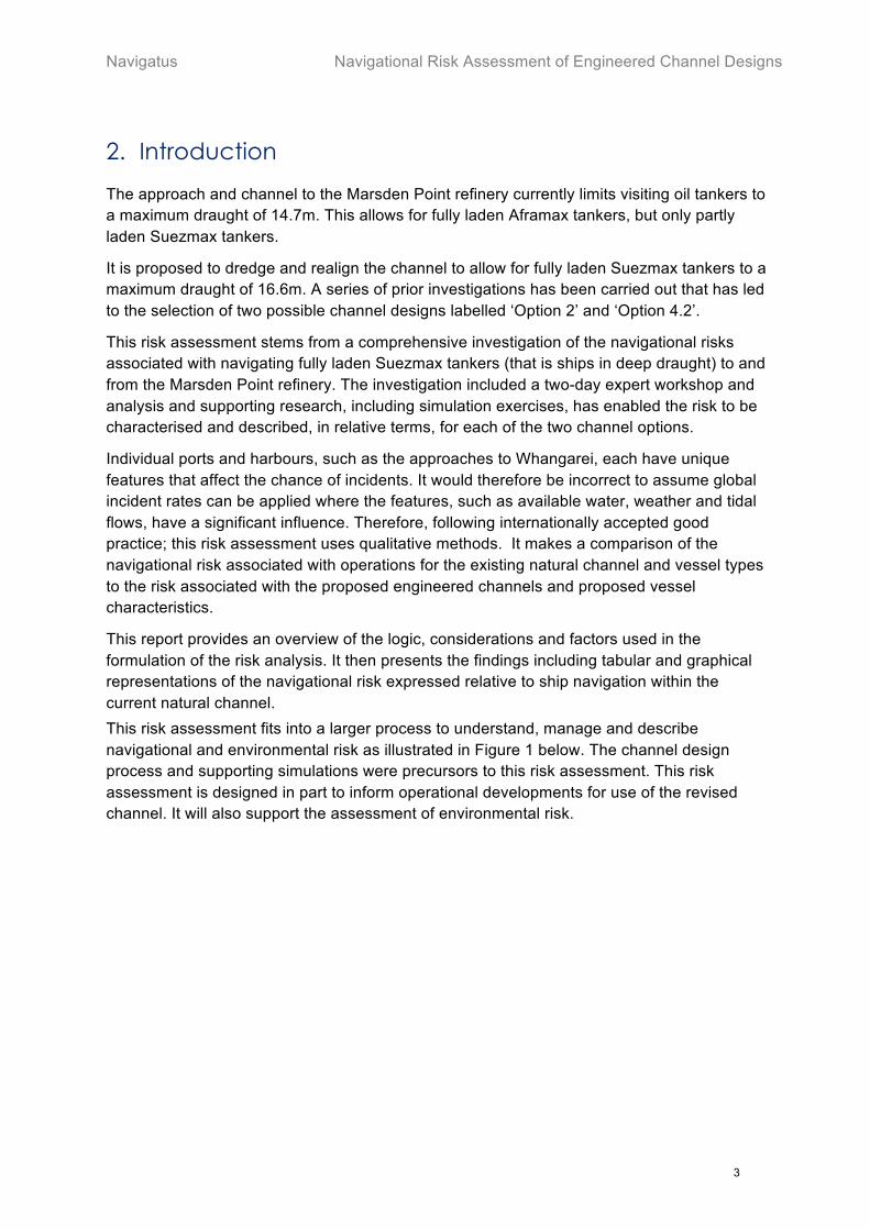
2. Introduction
The approach and channel to the Marsden Point refinery currently limits visiting oil tankers to a maximum draught of 14.7m. This allows for fully laden Aframax tankers, but only partly laden Suezmax tankers.
It is proposed to dredge and realign the channel to allow for fully laden Suezmax tankers to a maximum draught of 16.6m. A series of prior investigations has been carried out that has led to the selection of two possible channel designs labelled ‘Option 2’ and ‘Option 4.2’.
This risk assessment stems from a comprehensive investigation of the navigational risks associated with navigating fully laden Suezmax tankers (that is ships in deep draught) to and from the Marsden Point refinery. The investigation included a two-day expert workshop and analysis and supporting research, including simulation exercises, has enabled the risk to be characterised and described, in relative terms, for each of the two channel options.
Individual ports and harbours, such as the approaches to Whangarei, each have unique features that affect the chance of incidents. It would therefore be incorrect to assume global incident rates can be applied where the features, such as available water, weather and tidal flows, have a significant influence. Therefore, following internationally accepted good practice; this risk assessment uses qualitative methods. It makes a comparison of the navigational risk associated with operations for the existing natural channel and vessel types to the risk associated with the proposed engineered channels and proposed vessel characteristics.
This report provides an overview of the logic, considerations and factors used in the formulation of the risk analysis. It then presents the findings including tabular and graphical representations of the navigational risk expressed relative to ship navigation within the current natural channel. This risk assessment fits into a larger process to understand, manage and describe navigational and environmental risk as illustrated in Figure 1 below. The channel design process and supporting simulations were precursors to this risk assessment. This risk assessment is designed in part to inform operational developments for use of the revised channel. It will also support the assessment of environmental risk.

Navigational Risk Assessment of Engineered Channel Designs Navigatus
4
Figure 1 - Overall Process

Navigatus Navigational Risk Assessment of Engineered Channel Designs
5
3. Risk Assessment Process
The risk assessment followed the risk assessment part of the risk management process set out in AS/NZS ISO 31000:2009 Risk Management – Principles and Guidelines. The disciplined process was founded on a series of expert workshops supported by additional research and simulator studies.
The workshops were attended by staff from Refining NZ, North Tugz, Northport and the Harbourmaster who bought local expert knowledge in such areas as pilot and tug operation, procedure and practice, jetty management, and local navigation. Specialists from Be Software, Brisbane Marine Pilots, DNV GL and Royal HaskoningDHV who bought external expertise and viewpoints on subjects also supported the work of the workshop group. This included channel design and naval architecture as well as pilotage and general marine practice. Navigatus Consulting, independent specialist risk consultants, facilitated the workshops, carried out the assessment and prepared this report.
The workshop group first considered each reach of the existing channel and operation in detail. The hazards were identified and described, and the existing and potential mitigations to these hazards examined. The workshop group then considered the changes inherent in the two channel options, investigating each for the hazards and mitigations in turn. This process recognised the complexity of risk, including the concept of ‘layers of defence’ – that being the concept that for each hazard there are multiple and sometimes complementary mitigations as no one mitigation measure can be assumed to be completely effective. The work of the group was informed by a series of simulation runs and actual approaches and departures that had been held previously. The output from the workshop sessions was then also tested by a further series of simulation runs.
The unique nature of individual harbours and very limited record of ship incidents at Marsden Point means it is unrealistic to attempt to carry out a useful quantitative assessment of the risk associated with piloting large oil tankers at Marsden Point. However, the structured approach of the workshops, use of local and external expertise covering all relevant aspects of the operation and subsequent analysis means a relative qualitative assessment could be completed. This assessment was therefore designed to take into account the changes in the likelihood of an incident and any changes in the consequence, and thus is a measure of changes in risk. The process allowed a conclusion to be made on the overall level of risk associated with the proposed channel designs and therefore their acceptability.
The assessment of the navigational impacts of the dredged material after disposal at the designated disposal sites is also covered. Unlike the complex and in-depth consideration of the engineered designs, given the relatively simple matters involved, the assessment of the effect of the disposed material with regard to navigation is based upon professional judgement of Geraint Bermingham, the lead expert for the overall package of work covered by this report. This work is reported towards the end of each relevant section of this report.

Navigational Risk Assessment of Engineered Channel Designs Navigatus
6
4. Context
4.1. Navigational Area Considered
Whangarei Harbour, close to the northern tip of Bream Bay, stretches some 23km north-west from the entrance at Whangarei Heads to the town basin at Whangarei and is approximately 6km across at its widest. Much of the harbour is shallow with exposed mud banks and sand bars at low tide. The entrance to the harbour is comparatively narrow, less than 0.5 nm at Marsden Point. The expanse of the harbour, a spring tidal range of 2.3m at Marsden Point1 and the narrow entrance, results in significant tidal currents particularly at the entrance of the harbour. The chart of the harbour area indicates currents of 2.1 knots at Marsden Point and 3.1 knots at Home Point, with local information indicating localised higher rates of flow.
The Marsden Point refinery is located at the low-lying southern shore of the entrance to the Whangarei Harbour. The refinery has three jetties in the deep-water channel close to, and to the north of, Marsden Point. The larger oil tankers berth against both Jetty 1 (the crude oil terminal) and Jetty 2 together. The channel from the Fairway Buoy to the refinery is approximately 5 nm long and is well defined by a series of lit buoys.
The area considered in this risk assessment extends from the Fairway Buoy (S35° 53.25 E174° 33.15) 1.8nm off Busby Head to the Oil Refinery Jetty at Marsden Point (S35° 50.21 E174° 30.05). Specifically it considers the existing and proposed navigation channels defined and designed by Royal HaskoningDHV, and recommended for further consideration in their report2. These channels are linked to the dredging required to increase the channel depth to be able to accommodate a fully laden Suezmax tanker with a draught up to 16.6m.
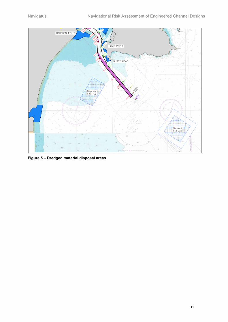
The locations of disposal sites that are also considered in this report are shown at Figure 53.
4.1.1. Existing Channel
In terms of navigation the main points of note on the existing channel are:
• The Fairway Buoy is the outermost buoy for ships approaching and departing Marsden Point. In theory ships can pass either side of the buoy. However, the ‘wave rider’ buoys which feed data to the Dynamic Under Keel Clearance system used to inform ships of safe entry are located 0.3 nm to the north west of the Fairway Buoy and form a prohibited area. The leading marks and Port Entry Light (PEL) at Marsden Point guiding ships into the channel set a line to the west of the Fairway Buoy.
• Buoys #1 and #2 mark the seaward end of the channel. There is a limiting depth of 14.7m between Buoy #1 and the Fairway Buoy.
• Buoys #3 and #6 are close to Busby Head, the outermost land extent. The channel turns to the north at this point.
1 LINZ Chart NZ5214 Marsden Point, 2014. 2 Royal Haskoning DHV. Refining NZ Crude Shipping Project. Shipping Channel – Concept Design Report. June 2016. 3 Tonkin + Taylor. NZ Refining Co Ltd, crude Freight Project, Planning Map Rev 0 dated Aug 16 (pre approval)

Navigatus Navigational Risk Assessment of Engineered Channel Designs
7
• Buoy #7 is close to Home Point. The coast from Busby Head around Home Point has a rocky foreshore and so is considered hazardous. There is a rocky outcrop extending from the Home Point shoreline to the edge of the channel 0.1 nm to the north east of Buoy #7. The outer extent of the rock is charted at 4.8m and so presents a significant hazard to deep draught ships. Although close to the edge of the channel, this rock is currently unmarked. There is a change in the channel alignment at this buoy, which requires that inward ships make a starboard turn at Buoy #3 changing to a port turn to Buoy #14. In effect the channel presents an ‘S’ bend offshore from Home Point.
• Buoy #14 marks the north-eastern extent of the boundary – the ebb shoal - of the Mair Bank, a large sand bank. It also marks a change in channel alignment as the end of the bend around Home Point.
• Sinclair Leading Lights align to show the channel to the Refinery Jetty.
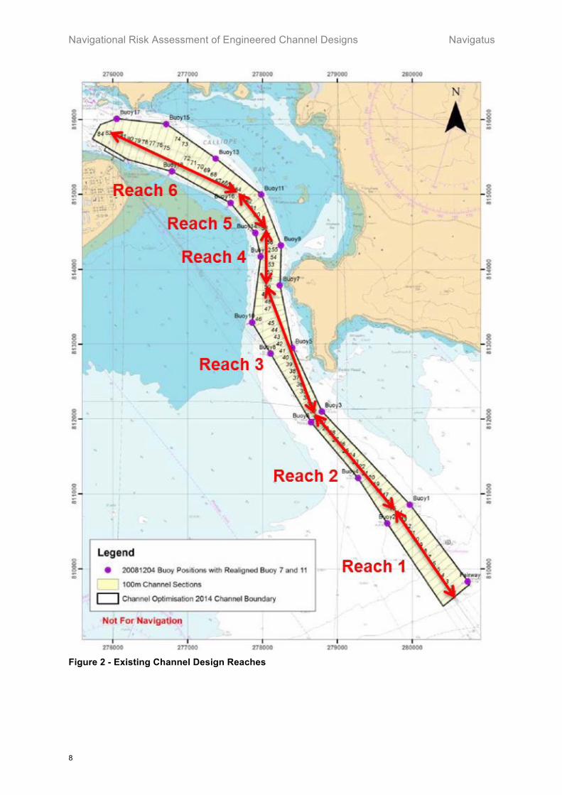
Royal HaskoningDHV4 defined the existing channel as 6 reaches with 5 changes of heading shown in Figure 2 below. The reaches are defined as:
1. Fairway Buoy to Buoys #1 and #2; 2. Buoys #1 and #2 to Buoys #3 and #6; 3. Buoys #3 and #6 to Buoy #7; 4. Buoy #7 to Buoy #14; 5. Buoy #14 to Buoy #16; 6. Buoy #16 to Buoy #17 (i.e. off the Oil Refinery Jetty)
4 Royal Haskoning DHV. Refining NZ Crude Shipping Project. Shipping Channel – Concept Design Report. June 2016.
Navigational Risk Assessment of Engineered Channel Designs Navigatus
8
Figure 2 - Existing Channel Design Reaches
Navigatus Navigational Risk Assessment of Engineered Channel Designs
9
4.1.2. Option 2 Channel
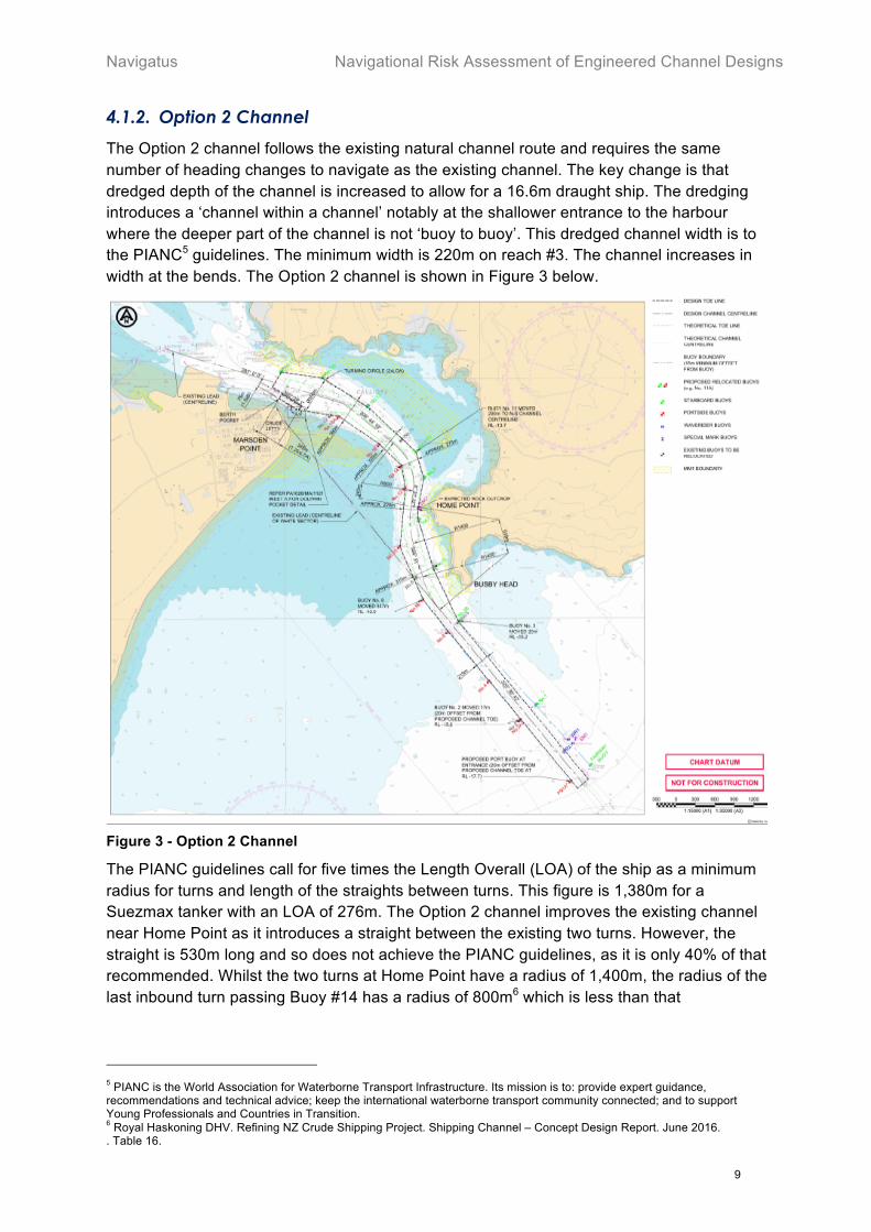
The Option 2 channel follows the existing natural channel route and requires the same number of heading changes to navigate as the existing channel. The key change is that dredged depth of the channel is increased to allow for a 16.6m draught ship. The dredging introduces a ‘channel within a channel’ notably at the shallower entrance to the harbour where the deeper part of the channel is not ‘buoy to buoy’. This dredged channel width is to the PIANC5 guidelines. The minimum width is 220m on reach #3. The channel increases in width at the bends. The Option 2 channel is shown in Figure 3 below.
Figure 3 - Option 2 Channel
The PIANC guidelines call for five times the Length Overall (LOA) of the ship as a minimum radius for turns and length of the straights between turns. This figure is 1,380m for a Suezmax tanker with an LOA of 276m. The Option 2 channel improves the existing channel near Home Point as it introduces a straight between the existing two turns. However, the straight is 530m long and so does not achieve the PIANC guidelines, as it is only 40% of that recommended. Whilst the two turns at Home Point have a radius of 1,400m, the radius of the last inbound turn passing Buoy #14 has a radius of 800m6 which is less than that
5 PIANC is the World Association for Waterborne Transport Infrastructure. Its mission is to: provide expert guidance, recommendations and technical advice; keep the international waterborne transport community connected; and to support Young Professionals and Countries in Transition. 6 Royal Haskoning DHV. Refining NZ Crude Shipping Project. Shipping Channel – Concept Design Report. June 2016. . Table 16.

Navigational Risk Assessment of Engineered Channel Designs Navigatus
10
recommended by the PIANC guidelines. This design includes adding a fixed mark to the outer limit of the rocky outcrop at Home Point.
4.1.3. Option 4.2 Channel
The Option 4.2 channel, shown in Figure 4 below, also allows for a 16.6m draught ship and differs from Option 2 in that it only has 2 turns and 3 primary headings. Dredging accordingly, and moving a number of the buoys achieves this. The first turn around Home Point has an extended radius of 1,800m with the second turn remaining at 800m7. The straight leg is extended in length to 894m while the channel is widened in places at the bends. Whilst the channel still does not fully achieve the PIANC guidelines it does offer improvements over Option 2. In particular ships will be on a steady, almost North-South, heading when they are passing Home Point and its rocky outcrop. This design is supported by the addition of 2 leading marks on the northern shore of Calliope Bay.
Figure 4 - Option 4.2 Channel
As with Option 2, this design includes adding a fixed mark to the outer limit of the rocky outcrop at Home Point.
7 Royal Haskoning DHV. Refining NZ Crude Shipping Project. Shipping Channel – Concept Design Report. June 2016. . Table 18.
Navigatus Navigational Risk Assessment of Engineered Channel Designs
11
Figure 5 – Dredged material disposal areas
Navigational Risk Assessment of Engineered Channel Designs Navigatus
12
4.2. Port/Pilotage Operation
Whangarei Harbour serves several significant commercial marine operations including:
• Marsden Point Refinery operated by Refining NZ – oil tankers.
• Marsden Point deep-water port operated by Northport – general cargo notably log-ships.
• Portland operated by Golden Bay Cement – cement carrier.
There are also a number of small ship repair facilities and boatyards closer to Whangarei.
4.2.1. Pilotage
Whangarei Harbour is subject to compulsory pilotage for all ships over 500 gross tonnes. North Tugz Limited provides the only pilotage service.
4.2.2. Current Towage Capacity
North Tugz is the provider of towage services in Whangarei Harbour. Currently the company uses a range of tugs8 to service the Marsden Point refinery:
• Bream Bay, Bollard pull: 69 tonne ahead, 68 tonne astern.
• Takahiwai, Bollard pull: 50 tonne.
• Marsden Bay, Bollard pull: 29 tonne ahead, 23 tonne astern.
• Kemp, Bollard pull: 14 tonne ahead, 9.5 tonne astern.
• Hobson, capable of Bollard pull: 3.3 tonne.
• Jack Guy a rigid hulled inflatable pilot boat (capable of providing a minor push only).
4.3. Ship Navigation Paths
The channel diagrams show a centre line of the channel. However the natural swing of a hull, the effect of wind and tide, and dynamic effects of a large ship making a turn means that this line does not represent the actual path that ships should steer. The optimal paths for a range of scenarios were explored using the series of simulation runs. The results form the basis of the design of the final preferred tracks.
4.4. Types of Ships Considered
Marsden Point Refinery can presently handle fully laden Aframax and partly laden Suezmax tankers with a maximum draught of 14.7m. The proposed dredging of the channel will allow a fully laden Suezmax tanker, with a draught of 16.6m and a greater displacement to enter on any given high tide. It is assumed that a tanker will arrive and discharge most, if not all, of its cargo at the refinery, and that it will not take on petroleum product for onward transit. Therefore the full and part laden tankers were only considered as arriving at the refinery. Tankers leaving the refinery were assumed to be in ballast with a reduced draught. Therefore, the study did not consider the case of a tanker departing fully laden. Whilst laden tankers tend to have a constant draught along their length, ballasted tankers tend to be deep
8 Plant information supplied by NorthTugz July 2016.
Navigatus Navigational Risk Assessment of Engineered Channel Designs
13
by the stern. It is noted that a ballasted ship will present more windage than a laden one due to greater freeboard.
The assessment also considered a typical log ship (bulk carrier).
It is noted that the only proposed change to current operations is the ability to allow fully laden Suezmax tankers to navigate to the berth.
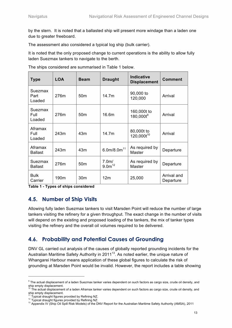
The ships considered are summarised in Table 1 below.
Type LOA Beam Draught Indicative Displacement Comment
Suezmax Part Loaded
276m 50m 14.7m 90,000 to 120,000 Arrival
Suezmax Full Loaded
276m 50m 16.6m 160,000t to 180,000t9 Arrival
Aframax Full Loaded
243m 43m 14.7m 80,000t to 120,000t10 Arrival
Aframax Ballast 243m 43m 6.0m/8.0m11 As required by
Master Departure
Suezmax Ballast 276m 50m 7.0m/
9.0m12 As required by Master Departure
Bulk Carrier 190m 30m 12m 25,000 Arrival and
Departure Table 1 - Types of ships considered
4.5. Number of Ship Visits
Allowing fully laden Suezmax tankers to visit Marsden Point will reduce the number of large tankers visiting the refinery for a given throughput. The exact change in the number of visits will depend on the existing and proposed loading of the tankers, the mix of tanker types visiting the refinery and the overall oil volumes required to be delivered.
4.6. Probability and Potential Causes of Grounding
DNV GL carried out analysis of the causes of globally reported grounding incidents for the Australian Maritime Safety Authority in 201113. As noted earlier, the unique nature of Whangarei Harbour means application of these global figures to calculate the risk of grounding at Marsden Point would be invalid. However, the report includes a table showing
9 The actual displacement of a laden Suezmax tanker varies dependent on such factors as cargo size, crude oil density, and ship empty displacement. 10 The actual displacement of a laden Aframax tanker varies dependent on such factors as cargo size, crude oil density, and ship empty displacement. 11 Typical draught figures provided by Refining NZ. 12 Typical draught figures provided by Refining NZ. 13 Appendix IV (Ship Oil Spill Risk Models) of the DNV Report for the Australian Maritime Safety Authority (AMSA), 2011
Navigational Risk Assessment of Engineered Channel Designs Navigatus
14
the causes of groundings, with 87% of groundings being attributable to ‘Human Error’ as opposed to ship engineering failures or external factors. This indicates that measures aimed at supporting the human being in the system (e.g. advanced aids, developed and proven procedures, high quality training), will be more effective at reducing risk than measures aimed at responding to potential engineering failures.
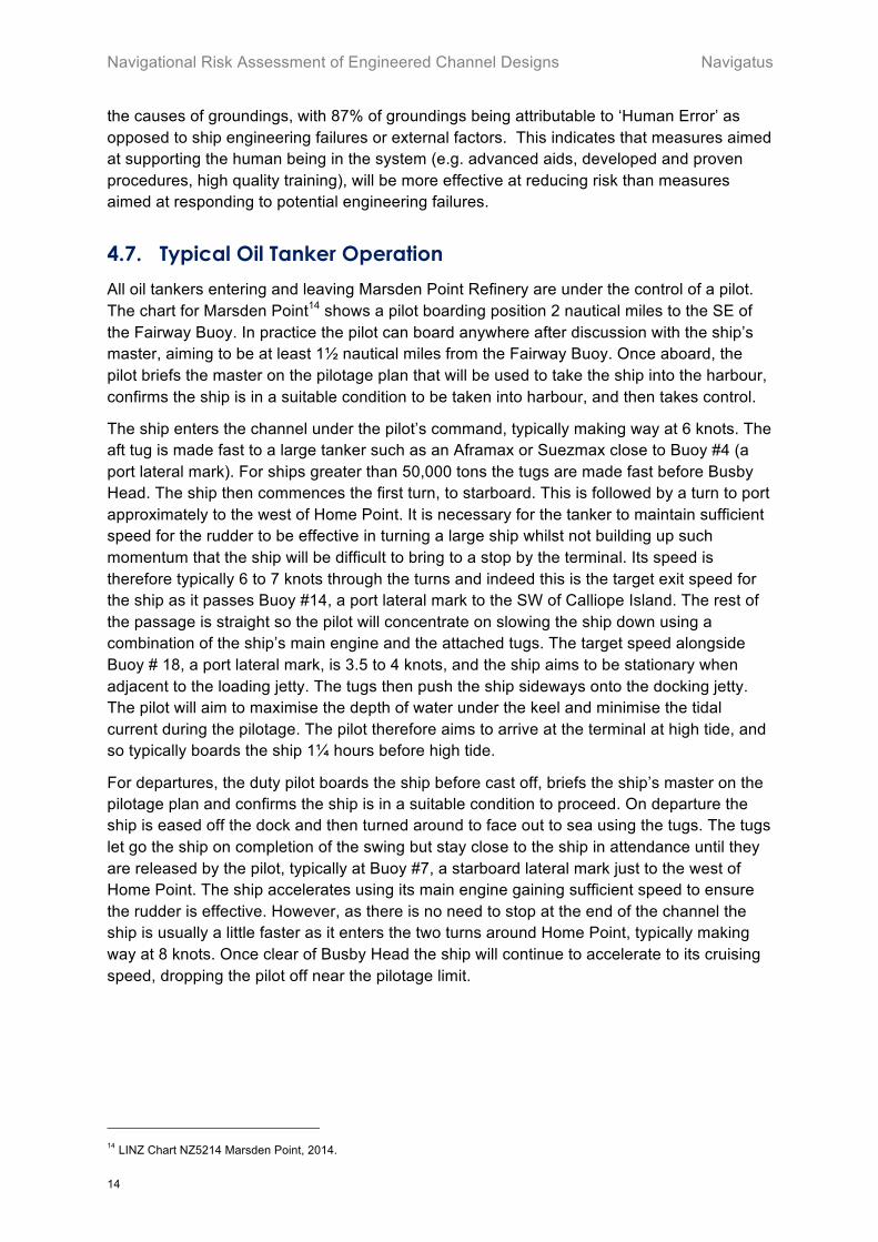
4.7. Typical Oil Tanker Operation
All oil tankers entering and leaving Marsden Point Refinery are under the control of a pilot. The chart for Marsden Point14 shows a pilot boarding position 2 nautical miles to the SE of the Fairway Buoy. In practice the pilot can board anywhere after discussion with the ship’s master, aiming to be at least 1½ nautical miles from the Fairway Buoy. Once aboard, the pilot briefs the master on the pilotage plan that will be used to take the ship into the harbour, confirms the ship is in a suitable condition to be taken into harbour, and then takes control.
The ship enters the channel under the pilot’s command, typically making way at 6 knots. The aft tug is made fast to a large tanker such as an Aframax or Suezmax close to Buoy #4 (a port lateral mark). For ships greater than 50,000 tons the tugs are made fast before Busby Head. The ship then commences the first turn, to starboard. This is followed by a turn to port approximately to the west of Home Point. It is necessary for the tanker to maintain sufficient speed for the rudder to be effective in turning a large ship whilst not building up such momentum that the ship will be difficult to bring to a stop by the terminal. Its speed is therefore typically 6 to 7 knots through the turns and indeed this is the target exit speed for the ship as it passes Buoy #14, a port lateral mark to the SW of Calliope Island. The rest of the passage is straight so the pilot will concentrate on slowing the ship down using a combination of the ship’s main engine and the attached tugs. The target speed alongside Buoy # 18, a port lateral mark, is 3.5 to 4 knots, and the ship aims to be stationary when adjacent to the loading jetty. The tugs then push the ship sideways onto the docking jetty. The pilot will aim to maximise the depth of water under the keel and minimise the tidal current during the pilotage. The pilot therefore aims to arrive at the terminal at high tide, and so typically boards the ship 1¼ hours before high tide.
For departures, the duty pilot boards the ship before cast off, briefs the ship’s master on the pilotage plan and confirms the ship is in a suitable condition to proceed. On departure the ship is eased off the dock and then turned around to face out to sea using the tugs. The tugs let go the ship on completion of the swing but stay close to the ship in attendance until they are released by the pilot, typically at Buoy #7, a starboard lateral mark just to the west of Home Point. The ship accelerates using its main engine gaining sufficient speed to ensure the rudder is effective. However, as there is no need to stop at the end of the channel the ship is usually a little faster as it enters the two turns around Home Point, typically making way at 8 knots. Once clear of Busby Head the ship will continue to accelerate to its cruising speed, dropping the pilot off near the pilotage limit.
14 LINZ Chart NZ5214 Marsden Point, 2014.
Navigatus Navigational Risk Assessment of Engineered Channel Designs
15
5. Risk Analysis
5.1. Undesirable Event
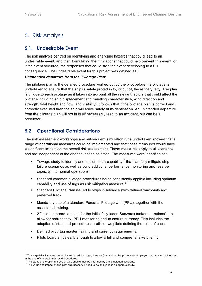
The risk analysis centred on identifying and analysing hazards that could lead to an undesirable event, and then formulating the mitigations that could help prevent this event, or if the event occurred, the responses that could stop the event developing to a full consequence. The undesirable event for this project was defined as: Unintended departure from the ‘Pilotage Plan’
The pilotage plan is the detailed procedure worked out by the pilot before the pilotage is undertaken to ensure that the ship is safely piloted in to, or out of, the refinery jetty. The plan is unique to each pilotage as it takes into account all the relevant factors that could affect the pilotage including ship displacement and handling characteristics, wind direction and strength, tidal height and flow, and visibility. It follows that if the pilotage plan is correct and correctly executed then the ship will arrive safely at its destination. An unintended departure from the pilotage plan will not in itself necessarily lead to an accident, but can be a precursor.
5.2. Operational Considerations
The risk assessment workshops and subsequent simulation runs undertaken showed that a range of operational measures could be implemented and that these measures would have a significant impact on the overall risk assessment. These measures apply to all scenarios and are independent of the channel option selected. The measures were identified as:
• Towage study to identify and implement a capability15 that can fully mitigate ship failure scenarios as well as build additional performance monitoring and reserve capacity into normal operations.
• Standard common pilotage procedures being consistently applied including optimum capability and use of tugs as risk mitigation measure16
• Standard Pilotage Plan issued to ships in advance (with defined waypoints and preferred track.
• Mandatory use of a standard Personal Pilotage Unit (PPU), together with the associated training.
• 2nd pilot on board, at least for the initial fully laden Suezmax tanker operations17, to allow for redundancy, PPU monitoring and to ensure currency. This includes the adoption of standard procedures to utilise two pilots defining the roles of each.
• Defined pilot/ tug master training and currency requirements.
• Pilots board ships early enough to allow a full and comprehensive briefing.
15 This capability includes the equipment used (i.e. tugs, lines etc.) as well as the procedures employed and training of the crew in the use of the equipment and procedures. 16 The study of the optimum use of tugs should also be informed by the simulation sessions. 17 The value and impact of two-pilot operations will need to be analysed in a separate study.

Navigational Risk Assessment of Engineered Channel Designs Navigatus
16
While some of these operational measures require development and input from a range of stakeholders (and are thus outside the scope of this review), our initial analysis indicated that the risk mitigation due to these measures is significant. This is supported by the DNV GL study showing that the overwhelming majority of ship groundings were caused by ‘human factors’. Indeed, given that all these measures are reasonably practical the overall navigational risk post construction of an engineered channel would not meet the ALARP18 criterion unless these measures were implemented. The following navigational risk assessment of the channel options therefore assumes these measures have been implemented in full as a pre-requisite to the use of the revised channel.
5.3. Channel Considerations
5.3.1. Channel Design
The two options considered were designed by Royal HaskoningDHV based on the PIANC guidelines.
As far as possible the engineered channels were designed to comply with the PIANC guidelines. These guidelines provide recommendations regarding minimum bend radius, channel width and length of straight sections. Meeting these recommendations was not possible throughout the full extent of the channel due to existing site constraints.
The international PIANC guidelines allow the existing and designed channels to be classified according to their ease of operation as follows:
• Optimum – Ideal under both operating and extreme conditions, no issues encountered.
• Adequate – Very good under operating conditions, manageable under extreme conditions.
• Marginal – Adequate under operating conditions but poor under extreme conditions.
• Inadequate – Poor under both operating and extreme conditions, may be considered unacceptable from a navigational risk perspective.
The Royal HaskoningDHV analysis of the channels according to these ratings has been superimposed on the channel option plots in Figure 6. If considered against the PIANC guidelines, the existing channel has a ‘Marginal’ area to the west and south of Busby Head, and as the channel passes Home Point. The existing channel is ‘Inadequate’ adjacent to Home Point. Option 2 shows an improvement, with the ‘Marginal’ area to the west of Busby Head reduced to one segment, and the ‘Marginal’ area past Home Point improved to ‘Adequate’. However, the ‘Inadequate’ section adjacent to Home Point remains. Option 4.2 is a further improvement on Option 2 with the segments adjacent to and past Home Point rated as ‘Adequate’. The bend radius between Busby Head and Home Point is also improved to rate as ‘Optimum’, while the segment just before Home Point is classed as ‘Adequate’.
The channel options were trialled in a portable simulator19. The pilots involved showed a clear preference for Option 4.2 over Option 2 as the channel simplified the arrival approach and gave more sea room around the critical area at Buoy #14 (inner curve near the Mair
19 Subsequent full bridge simulations were carried at the Marine Simulation Centre of New Zealand Maritime School, Auckland. 19 Subsequent full bridge simulations were carried at the Marine Simulation Centre of New Zealand Maritime School, Auckland.

Navigatus Navigational Risk Assessment of Engineered Channel Designs
17
Bank), improved clearance from, and allowed a straight near North-South aligned section past, the rocky outcrop at Home Point.
Figure 6 - Channel classification against PIANC

Navigational Risk Assessment of Engineered Channel Designs Navigatus
18
5.3.2. Dynamic Under Keel Clearance (DUKC) System
The DUKC system uses wave rider buoys and tidal data to calculate the depth of water available for ships in a channel taking into account the effect of tide and waves as well as the dynamic characteristics of ships. Ships and ports can therefore determine whether a ship can safely enter a port. The system has been deployed at many ports around the world and has proved effective.
Marsden Point uses a DUKC system to assist with the decision of whether to allow a ship to proceed into port under the conditions prevailing when the ship is due and on arrival at the Fairway Buoy and on arrival at the Buoy.
5.4. Detailed Reach Analysis – Existing Channel
As noted in section 4.1.1 the existing channel to Marsden Point can be considered as a series of six reaches. This allows a detailed analysis, considering each reach in turn to be effectively carried out. This in turn enables a disciplined and progressive consideration of the threats and associated mitigations of the existing channel to the level of detail required for a comprehensive analysis.
5.4.1. Consistent Threats and Mitigations
Some threats and mitigations are evident throughout the pilotage and are largely irrespective of the reach and whether the ship is arriving or departing. These are:
Threat: Weather. Weather is always a factor for maritime operations, but existing Standard Operating Procedures (SOPs) provide appropriate guidance. A sudden loss of visibility is considered a possibility at Marsden Point but this is mitigated by knowledge of local weather and having good navigation cues such as buoyage and leading lights. The upper extent of the channel does offer protection from wind, waves and swell.
Threat: Engineering. There is the ever-present possibility of an engineering event affecting the ship’s ability to manoeuvre. The SOPs, readiness of the bridge team and the general understanding of the local sea conditions, currents and approach channel and the consequent priorities are factors pilots would consider in such circumstances.
Threat: Pilot. Issues with the pilot, either in the case of the pilot becoming incapacitated or, given the relatively limited number of large tankers visiting Marsden Point, pilot currency, are hazards.
A possible mitigation is to take two pilots on a pilotage. One pilot would have the conn with the other monitoring, assisting and being available to step in. Both pilots would gain operational experience. The human factors associated with two qualified pilots working together would have to be considered.
Mitigation: PPU. The PPU is a specialist portable chart plotter available for pilots. It is highly accurate and displays programmed track, current position and a prediction of the ship’s path and position. The PPU also enables pre-programmed waypoints and paths to be followed, and can take inputs from the ship’s own navigation system. It is thus an effective tool that provides significant assistance to the pilot and can mitigate a range of threats; for example, the pilot’s PPU is the most effective mitigation in the event of loss of visibility. At the time of the workshops pilots at Marden Point did not universally use a ‘standard’ PPU, although at the time of the risk assessment study itself, North Tugz had commenced exploring
Navigatus Navigational Risk Assessment of Engineered Channel Designs
19
formalising its use. In the time since then and the date of this report, PPU use has become a standard requirement for all transits of large vessels.
5.4.2. Arrival - Reach 1
Reach 1 occurs between the Fairway Buoy and the start of the defined channel at Buoys #1 and #2. Whilst this is open water there are still threats and mitigations to consider.
Ship Preparation. The threats in Reach 1 as identified are largely concerned with the ship’s preparation for the approach and arrival. Late readiness for harbour entry or not being correctly positioned means the ship may miss the narrow tide ‘window’ that allows the ship to arrive at the berth at high water slack tide. Lateness for any reason including defects on the ship, will result in the pilot having limited time, and so increased pressure, to decide whether to bring the ship in or not. The mitigations for these are essentially monitoring the ship’s state and crew readiness. The IMO20 requirements that require ships to test and configure steering gear prior to entering a harbour acts as a powerful mitigation.
Pilotage Planning. Inadequate preparation could result in the ship’s master and the pilot having differing understandings of the arrival procedure, pilotage plan and planned use of tugs, an undesirable situation that can be prevented by use of common procedures and by planning ahead. Forward planning could be achieved by sending a detailed standard pilotage plan to the ship well in advance. Establishing and applying standard pilotage and towage procedures for large ships could also be an additional and effective mitigation.
5.4.3. Arrival - Reach 2
Reach 2 represents the point at which the ship is within the narrowing channel and where the coast to the north presents a higher level of potential consequence. The relevant threats are largely the same as for Reach 1; however, departure from the planned path is more pertinent. The threat of a late defect notification is not so relevant on this reach as it is taken the pilot has been briefed by the master and has ensured the ship has the required capability to safely complete the approach and berthing.
Departure from Planned Path. A threat of the ship departing the planned path is evident on this reach, as the ship needs to more closely follow the required path in the channel from this point on. Given the ship is closer in, the Port Entry Light (PEL) should be more effective. At the time of the analysis, it was recognised that the formal use of a PPU would provide a very effective method for enabling and ensuring cross track error (relative to the defined preferred path) is monitored and indicating the exact ship positioning relative to hazards. As noted above, since that time routine PPU use has been introduced.
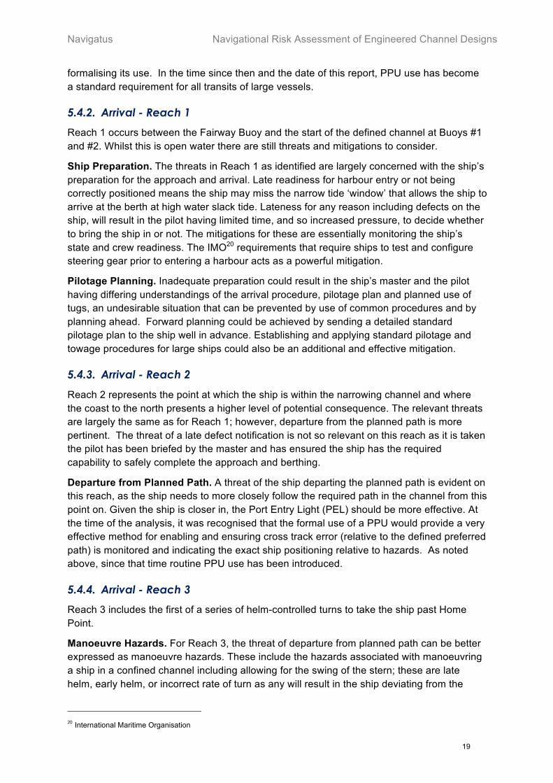
5.4.4. Arrival - Reach 3
Reach 3 includes the first of a series of helm-controlled turns to take the ship past Home Point.
Manoeuvre Hazards. For Reach 3, the threat of departure from planned path can be better expressed as manoeuvre hazards. These include the hazards associated with manoeuvring a ship in a confined channel including allowing for the swing of the stern; these are late helm, early helm, or incorrect rate of turn as any will result in the ship deviating from the
20 International Maritime Organisation
Navigational Risk Assessment of Engineered Channel Designs Navigatus
20
intended path. This is compounded in the current channel by the lack of a defined or steady heading between the turns to starboard and then the turn to port. There are however a number of mitigations, including that the manoeuvre is well practiced and understood by the pilots as well as effective use of PPUs.
Tugs. Of note, tugs will have taken lines at the start of this reach. However, as large ships need to retain sufficient speed for steerage, typically 6 to 8 knots and as the current tugs are not ‘escort tugs’, the tugs ability to assist the ship is limited on this reach. In the case of an engineering failure onboard the tanker, or pilot error, tugs need to be in a position to be able to respond in sufficient time to prevent grounding. In addition, tug crews need suitable response procedures and to be trained and current in their use.
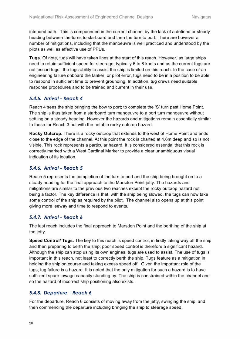
5.4.5. Arrival - Reach 4
Reach 4 sees the ship bringing the bow to port; to complete the ‘S’ turn past Home Point. The ship is thus taken from a starboard turn manoeuvre to a port turn manoeuvre without settling on a steady heading. However the hazards and mitigations remain essentially similar to those for Reach 3 but with the notable rocky outcrop hazard.
Rocky Outcrop. There is a rocky outcrop that extends to the west of Home Point and ends close to the edge of the channel. At this point the rock is charted at 4.6m deep and so is not visible. This rock represents a particular hazard. It is considered essential that this rock is correctly marked with a West Cardinal Marker to provide a clear unambiguous visual indication of its location.
5.4.6. Arrival - Reach 5
Reach 5 represents the completion of the turn to port and the ship being brought on to a steady heading for the final approach to the Marsden Point jetty. The hazards and mitigations are similar to the previous two reaches except the rocky outcrop hazard not being a factor. The key difference is that, with the ship being slowed, the tugs can now take some control of the ship as required by the pilot. The channel also opens up at this point giving more leeway and time to respond to events.
5.4.7. Arrival - Reach 6
The last reach includes the final approach to Marsden Point and the berthing of the ship at the jetty.
Speed Control/ Tugs. The key to this reach is speed control, in firstly taking way off the ship and then preparing to berth the ship; poor speed control is therefore a significant hazard. Although the ship can stop using its own engines, tugs are used to assist. The use of tugs is important in this reach, not least to correctly berth the ship. Tugs feature as a mitigation in holding the ship on course and taking excess speed off. Given the important role of the tugs, tug failure is a hazard. It is noted that the only mitigation for such a hazard is to have sufficient spare towage capacity standing by. The ship is constrained within the channel and so the hazard of incorrect ship positioning also exists.
5.4.8. Departure – Reach 6
For the departure, Reach 6 consists of moving away from the jetty, swinging the ship, and then commencing the departure including bringing the ship to steerage speed.

Navigatus Navigational Risk Assessment of Engineered Channel Designs
21
Ship Preparation. The departure naturally allows more time for preparation as the ship is alongside and the pilot can easily board almost any time. The tidal window is relevant to the start of the passage so departure can be accurately aligned to a favourable tide. Major work on the ship’s propulsion and steering is prohibited when alongside so mechanically the ship will be in a known state as it has already been piloted onto the jetty.
Tugs. As with the berthing, tugs are essential to the casting off and turning operation so the threat of tug failure remains until the tugs are let go. Again the only effective mitigation is to have sufficient towage capability standing by.
Departure from Planned Path. The ship is in a channel and so must remain on or close to the planned path. Initially this is achieved using the attendant tugs. However, as the ship gains speed it gains steerage and so is more resilient to the threat of the loss of tug assistance.
5.4.9. Departure – Reach 5
On the departure Reach 5 introduces an easy turn to starboard whilst the ship accelerates. The ship will have gained steerage by the start of Reach 5.
Tugs. The ship has gained steerage and so tugs are not required to direct the direction of the ship’s travel. However, the ship may still need assistance in the event of an engineering failure such as a power blackout or steering system failure. Whilst the tugs will have let go, they still need to remain in close attendance to the ship. As with the arrival reaches, the tugs would need to be in a position to be able to respond to a situation in sufficient time. Simulation sessions could provide guidance to the best positions of the tugs and these should then be incorporated into SOPs.
5.4.10. Departure – Reach 4
Reach 4 sees the ship increasing the turn rate to starboard and passing Home Point.
Manoeuvre Hazards. The manoeuvring hazards on departure are similar to those on arrival. The incorrect application of helm will result in the ship deviating from the intended path. Similar mitigations as for arrival are available or in place.
Use of Tugs: The pilots emphasised that they currently ‘drive’ the ships though the ‘S” bend by Home Point. This means that the initial focus is to accelerate the ship to at least manoeuvring speed (over 5 knots) and usually 8 knots. Once up to these speeds, the ship will have sufficient momentum to reach the open sea in the event of an engine failure. The power of the rudder is such at these speeds that specific rudder hard-over failures may not be able to be contained unless the tugs are prepositioned, with suitable response procedures, and with crews trained and current in their use.
5.4.11. Departure – Reach 3
Reach 3 involves the change from a starboard turn to a port turn to complete the ‘S’ turn after passing Home Point. This is similar to the arrival Reach 4 and so the threats and mitigations are similar, albeit that the ship is well underway which gives greater control.
Ship Momentum. The ship has gained speed and thus momentum by the start of Reach 3. This provides a major mitigation, as a ship would have sufficient momentum to reach the open sea in the event of a propulsion failure. Any tugs in attendance would only be required
Navigational Risk Assessment of Engineered Channel Designs Navigatus
22
to provide support in the event of loss of propulsion or steerage, or a rudder hard-over failure.
5.4.12. Departure – Reach 2
On the departure in Reach 2 the ship lines up on the straight channel heading out to the open sea. The only navigational hazard is the shoaling water north and south of the channel and thus the threat is of the ship failing to maintain the proper path. This is similar to the hazard noted on arrival and, given the tugs are no longer in attendance, has the same range of mitigations; however, it is noted that the expected part-laden, or in-ballast draught of the ship means the ‘channel within a channel’ should not be a direct threat.
5.4.13. Departure – Reach 1
The departure on Reach 1 is a continuation of Reach 2 and has the similar threats and mitigations.
5.4.14. Responses
It is readily apparent that the responses to an unintended departure from the pilotage plan as planned are the same for arrival or departure.
Responses. The judicious use of the ship’s propulsion and rudder may allow the pilot to avoid contact or grounding, and even restore the ship to its planned course; however given the narrowness of the channel combined with the expected headway, a response to a rudder hard over failure may not be possible. The pilot’s knowledge and use of the tide and current may help limit the impact on grounding. The tugs could provide towage and so manoeuvre the ship to safety; however, as noted above, this capability is limited by the speed of the ship at any given time, the positioning of the tugs and their capability. Finally, if the ship is making limited headway, typically less than 3 knots, the ship may be able to drop anchor to aid control of positioning.
Navigatus Navigational Risk Assessment of Engineered Channel Designs
23
5.5. Comparative Analysis
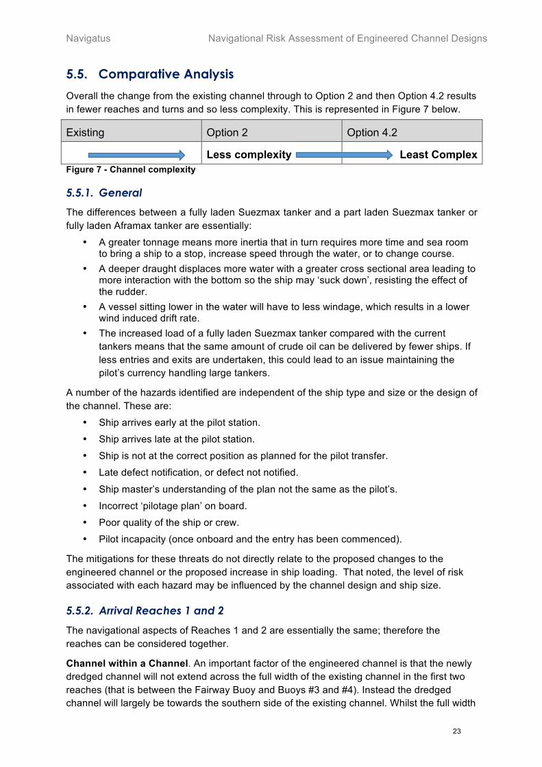
Overall the change from the existing channel through to Option 2 and then Option 4.2 results in fewer reaches and turns and so less complexity. This is represented in Figure 7 below.
Existing Option 2 Option 4.2
Less complexity Least Complex Figure 7 - Channel complexity
5.5.1. General
The differences between a fully laden Suezmax tanker and a part laden Suezmax tanker or fully laden Aframax tanker are essentially:
• A greater tonnage means more inertia that in turn requires more time and sea room to bring a ship to a stop, increase speed through the water, or to change course.
• A deeper draught displaces more water with a greater cross sectional area leading to more interaction with the bottom so the ship may ‘suck down’, resisting the effect of the rudder.
• A vessel sitting lower in the water will have to less windage, which results in a lower wind induced drift rate.
• The increased load of a fully laden Suezmax tanker compared with the current tankers means that the same amount of crude oil can be delivered by fewer ships. If less entries and exits are undertaken, this could lead to an issue maintaining the pilot’s currency handling large tankers.
A number of the hazards identified are independent of the ship type and size or the design of the channel. These are:
• Ship arrives early at the pilot station.
• Ship arrives late at the pilot station.
• Ship is not at the correct position as planned for the pilot transfer.
• Late defect notification, or defect not notified.
• Ship master’s understanding of the plan not the same as the pilot’s.
• Incorrect ‘pilotage plan’ on board.
• Poor quality of the ship or crew.
• Pilot incapacity (once onboard and the entry has been commenced).
The mitigations for these threats do not directly relate to the proposed changes to the engineered channel or the proposed increase in ship loading. That noted, the level of risk associated with each hazard may be influenced by the channel design and ship size.
5.5.2. Arrival Reaches 1 and 2
The navigational aspects of Reaches 1 and 2 are essentially the same; therefore the reaches can be considered together.
Channel within a Channel. An important factor of the engineered channel is that the newly dredged channel will not extend across the full width of the existing channel in the first two reaches (that is between the Fairway Buoy and Buoys #3 and #4). Instead the dredged channel will largely be towards the southern side of the existing channel. Whilst the full width
Navigational Risk Assessment of Engineered Channel Designs Navigatus
24
of the natural channel will be available for shallower draught ships including log carriers, the deeper draught oil tankers will be constrained to the narrower channel. The dredged channel meets PIANC recommendations and has been shown to be practical in simulation runs. It thus offers a reasonable balance between operations, environmental impact and cost. The lateral buoys only mark the existing channel; however, the engineered channels would align to the PEL and leading marks.
Navigational Aspects. For this part of the channel, options 2 and 4.2 are identical. The key navigational hazards of both options arise from the ‘channel within a channel’ caused by the proposed engineered channel dredging being limited to the south side of the marked channel. Factors considered were:
• The existing channel has a PEL to guide ships in and this is aligned to the channel on Reach 1; however there are questions over the effective range of the PEL, in terms of accuracy with distance compounded by visibility during the day. This uncertainty relates to the effectiveness of this mitigation and hence the level of risk. It is considered that the PEL is of only limited use for the outer reaches and is not as effective for determining rate of change as lead marks.
• PPU for pilots are now commonly used globally and are known to be an accurate and effective aid for pilots. At the time of the study, PPU use was not formallised or mandated locally and PPU practice was not common across the pilots. Mandated use of PPUs has since been investigated and introduced by North Tugz. It therefore follows that, use of PPU while navigating the new channel assumed for all tanker passages.
• The existing port channel buoys will mark the southern side of the dredged channel; however, the first starboard channel buoy (Buoy #1) will not mark the edge of the dredged channel. It is noted that the current channel is deep enough for most ships entering Whangarei and that repositioning the starboard channel buoys would unduly constrain all ships.
Sea Room. The larger ships require more sea room to manoeuvre, and thus the ‘abort point’ that is the latest point at which a ship could come to a complete stop or turnabout before entering the channel, would need to be further out to sea.
5.5.3. Arrival Reaches 3 and 4
As with the previous two reaches, Reaches 3 and 4 are navigationally very similar and so are considered together. These reaches are the most critical part of the pilotage, as this is where the ship executes the turns near Home Point. Home Point is notable due to there being the rocky shore to the north and east and an outcrop 4.6m below Chart Datum close to Buoy #7 at the end of Reach 4 that presents a particular hazard.
Overall Differences Between Options: There are differences between options 2 and 4.2 on Reaches 3 and 4. Option 2 has a short straight section of some 500m between the first, starboard, turn, and the next two port turns. Option 4.2 has a longer straight of approximately 900m between the completion of a starboard turn and the following port turn. In addition, whilst Buoy #11 is repositioned in Option 2, Option 4.2 sees Buoys #12 and #14 repositioned as well – each giving greater sea room. Option 4.2 therefore benefits all ships through a series of complementary benefits.
Navigatus Navigational Risk Assessment of Engineered Channel Designs
25
The workshop group could find no discernible difference in the factors considered between the Suezmax and Aframax ship types.
Navigational Aspects. The existing channel presents a complex compound curved path and clearances that do not meet the PIANC requirements for an engineered channel. Option 2 requires the pilot to steer a continually changing path with complex curves. There is an intermediate straight but it is too short to allow the ship to settle between turns. Therefore neither the existing channel nor Option 2 allow an opportunity to use leads or similar aids to line the ship up mid turn. Moreover on both channels the ship is in the process of changing from starboard turn to port turn near the key hazard (the rock outcrop). Option 2 does have slightly more sea room than the existing channel.
Option 4.2 allows for a longer straight leg between two turns. It is a simpler path allowing the ship to be on a steady bearing as it passes Home Point and the rocky outcrop. This straight leg is very close to a North-South heading and if fitted, leads in Calliope Bay will enable an excellent ability to externally confirm the ship’s cross track and positioning ahead of the next turn. The straight leg also allows for time to correct any cross track error or excess speed. Option 4.2 offers an increase in sea room over Option 2 and is also better aligned to the natural current flow in the channel. In particular Option 4.2 will also give improved clearance from Home Point on departure.
5.5.4. Arrival Reaches 5 and 6
Navigationally Reaches 5 and 6 are similar and so can be considered together.
Differences Between Options: Reaches 5 and 6 are the same for Options 2 and 4.2. Both options require a repositioning of Buoys #16 and #18 to minimise dredging along the channel edge.
Navigational Aspects. The engineered channels, Options 2 and 4.2, both offer a slight increase in sea room over the existing channel. However, the resultant advantage is only considered marginal.
Taking Way off the Ship: The pilots stated that at speeds of 3 knots an Aframax tanker’s engines can be expected to be able to bring a ship to a stop in its own length without the aid of tugs. It was noted that the greater tonnage and increased draught of the fully laden Suezmax ship means it will take more sea room to take way off the ship and more time to complete the berthing. This means that manoeuvres will have to be started earlier than for the part laden Suezmax or fully laden Aframax tankers; however, it is considered that at slow speeds the additional sea room required was slight. It is therefore considered there will be reserve power available in the ship’s main engine and the use of tugs to slow the ship is desirable, but not essential. This manoeuvre has been demonstrated in simulation runs.
Berthing: There are very tight limits on speeds and docking angles when berthing ships. Whilst a fully laden Suezmax tanker has more mass than the existing tankers, the manoeuvre is undertaken at very low speed. Significant expertise has been built up over the years and it is considered that this expertise could be transferred to ships carrying larger cargo without any issues.
Navigational Risk Assessment of Engineered Channel Designs Navigatus
26
5.5.5. Departure Reaches 6 to 3
Differences in Ships: It was noted that ships will almost always depart part laden or in ballast, and thus draw no more than 13m. There will therefore be no difference in the ships compared to those currently used.
Differences between Options. As with the arrival the additional sea room available in Option 2 over the existing channel is of benefit, and the further increased sea room in Option 4.2 is of further benefit. In particular, the repositioning of Buoy #14 in Option 4.2 significantly opens out the first turn of the series taking the ship around Home Point. Likewise the straight section between the turns and passing the submerged rock at Home Point is a significant benefit and reduces the risk in this area.
5.5.6. Departure Reaches 2 and 1
The only change to navigation for Reaches 2 and 1 is the ‘channel within a channel’. However, it was noted that the whole of the buoyed channel would have sufficient depth to accommodate a ship of 13m draught. Therefore this change is not relevant and thus the risks associated with Reaches 2 and 1 will be unchanged.
Navigatus Navigational Risk Assessment of Engineered Channel Designs
27
5.6. Consequences
Risk is a combination of likelihood and consequence. To this point of the report the analysis has concentrated on the likelihood of an incident and the mitigations necessary to reduce that likelihood to an acceptable level. Indeed, given that all threats have been identified and analysed, it could be argued that implementing all the mitigations would reduce the likelihood but have no effect on consequence which, given the larger ships, may be higher. The responses to the defined undesirable event, also discussed earlier, would further reduce the likelihood of a consequence. A complete risk analysis calls for the consideration of all levels of consequence.
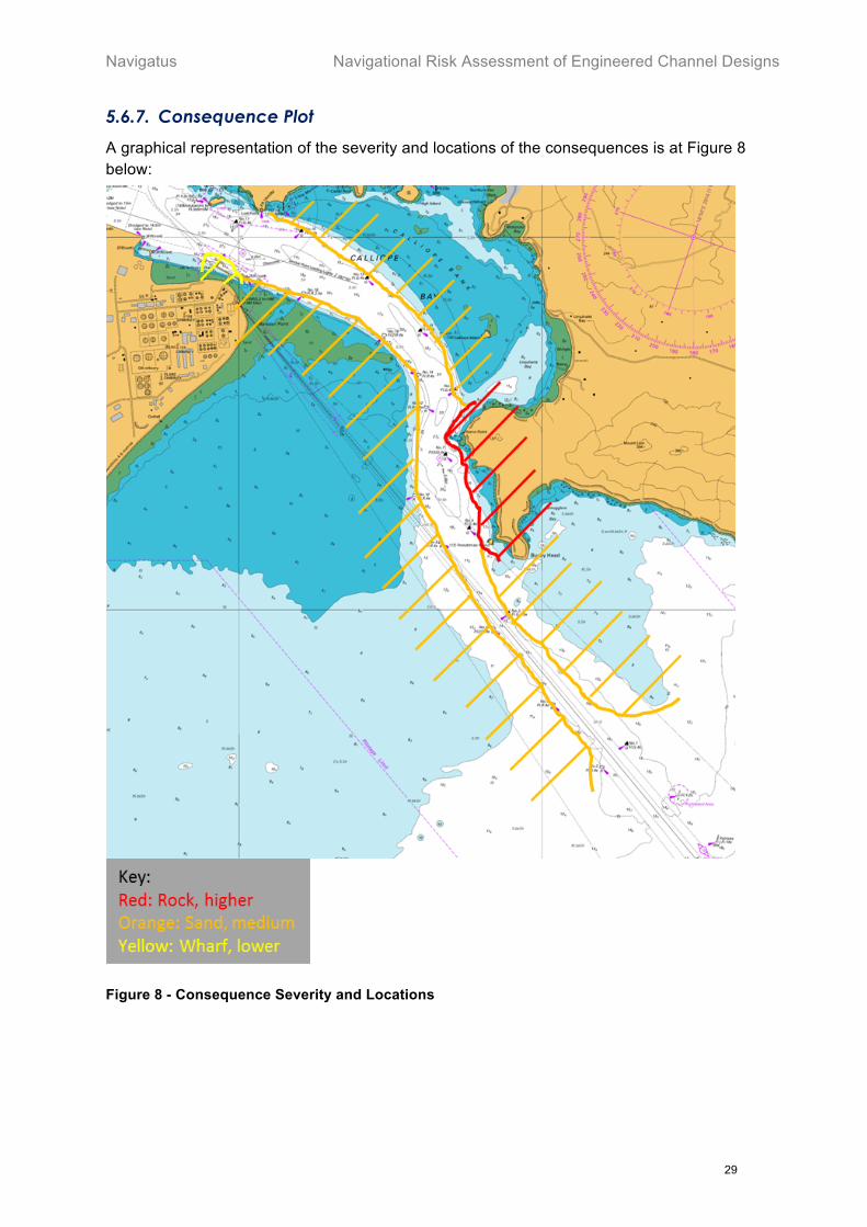
Possible Consequences. There are six potentially significant consequences as follows:
• Contact with buoy
• Heavy contact with jetty (Reach 6 only)
• Grounding on sand
• Contact with sand
• Grounding on rock (Reaches 3 and 4 only)
• Contact with rock (Reaches 3 and 4 only)
5.6.1. Contact with Buoy
Contact with a buoy would almost certainly be a glancing blow with the buoy sliding down the side of the ship’s hull for some distance. The buoys are secured by a chain and bottom tackle and so able to move with the impact and lessen the force transmitted between the ship and buoy. The damage would be limited to scrapes, at worst no more than some minor denting of the platting of the outer hull. Overall the consequence would be very minor.
5.6.2. Heavy Contact with Jetty
The limiting lateral speed for berthing is 0.15 m/s. Higher closing speeds would result in a heavy contact on berthing. In the past some ships have made heavy contact with the breasting dolphin; however, buffers on the dolphins limited any damage to the ships to cosmetic marks. In one case a dolphin, was knocked out of alignment while the ship remained undamaged. This would suggest that, as is the design intent, even given heavy contact with a fully laden Suezmax tanker, penetration of the outer hull plating would not be expected.
5.6.3. Grounding on Sand
A ship that was well off-track would contact the edge of the channel and could ground. In the case of an impact at a shallow angle a firm grounding is unlikely. In the case of a steeper frontal impact, it is almost certain the propulsion and steering systems would be undamaged. The bow sections are likely to suffer buckling to the outer plates and damage to the intervening structure. It is possible this damage to the structure could cause limited damage to the inner hull and tanks; however the collision bulkhead design of all tankers in designed to protect the watertight integrity of the main hull and so makes this unlikely. A minor oil leak from the bilges of the void spaces is possible. The key factors after grounding would be the subsequent sea state and weather. It was noted by the naval architect that tankers’ forward and lower hull plates tend to be heavy and so resistant to rupture. However, the movement

Navigational Risk Assessment of Engineered Channel Designs Navigatus
28
caused by swells would be expected to increase the damage to the ship and over time may cause plate failure.
5.6.4. Contact with Sand
Contact with the bottom sand without grounding would almost certainly be the case after a glancing blow with the side of the channel. It is likely the tanker would suffer some deformation of the outer hull plates and buckling of these plates is a possibility. There is a chance of damage to the structure between the outer and inner hulls. However, damage to the inner hull and oil tanks is considered highly unlikely. The glancing or sliding nature of the blow means that it is likely that the propulsion and steering systems would be unaffected. Cracking associated with heavy buckling of the outer plates could lead to slow flooding of the void sections of the hull and an increase in the ship’s draught. However, it is considered likely the ship would still be able to continue to the berth and to be brought alongside safely.
5.6.5. Grounding on Rock
Given the high pressures and potential cutting action, grounding on rock would be expected to cause considerably more damage than grounding on sand. This damage would be to the fore part of the ship, causing major damage to the forward hull plates and structure leading to flooding of the ship’s forepeak. Given the ship would likely continue to move after initial contact, it is possible that this damage would extend down the strakes and potentially damage the inner hull leading to more extensive flooding and leakage of oil. Clearly the extent of the damage would depend on the impact speed and extent of collision, and time in contact. Given the tonnage involved and the limited size of the nearby rocks it is unlikely the ship would not ride up over the rock – rather it would sustain damage to the hull plating and associated structure as it was being deflected laterally. However, as the impact would be to the side parts, the naval architect considered it extremely unlikely that the ship would become fast on the rock; a situation that could rapidly damage a ship beyond recovery (as per the MV Rena). As with grounding on sand, the full extent of the damage would depend on the speed and angle at which the ship grounded. The consequences of grounding on a rock will almost certainly be severe. It is of note that should a tank be ruptured, considerable oil leakage would be expected.
5.6.6. Contact with Rock
A glancing or passing contact with a rock would have notably greater consequences than a similar contact with sand. It is highly likely that hull plates would be buckled and quite possibly torn leading to relatively fast flooding of the void spaces. The structure between the hulls would also most likely suffer damage. It is quite possible that the inner hull and tanks would be breached which would lead to significant oil spillage. The extent of the damage would depend on the speed and angle of the ship at contact. Given a speed of 6 to 8 knots around Home Point, the damage could extend for a significant distance along the hull. It was noted that the end of the rocky outcrop off Home Point is some 5m below the sea surface and so would cause damage to a ship from about 7m and below. A particular consequence of note would be if the glancing contact included the stern. Given the double hull, spaces may also have taken on water (and so vessel displacement increased), an effect that could be significant. The consequences of glancing contact with a rock would therefore be severe.
Navigatus Navigational Risk Assessment of Engineered Channel Designs
29
5.6.7. Consequence Plot
A graphical representation of the severity and locations of the consequences is at Figure 8 below:
Figure 8 - Consequence Severity and Locations

Navigational Risk Assessment of Engineered Channel Designs Navigatus
30
5.7. Impact of dredged material disposal sites.
The consideration of the effect on navigation of the disposed dredged material is based on information reported in Section 2.2 of the Dredging and Disposal Options - Synthesis Report21. Other information considered came from the Tonkin and Taylor22, and the MetOcean modelling report23.
The key features that underpin this assessment are noted to be:
• Area 3-2 is situated 45 m below Chart Datum.
o The average height of the placement mound will be not more than 4 m, which equates to < 9% of the natural water depth.
o The effect on the surface will be imperceptible.
• Area 1-2 is an area of seabed situated on the southern end of the ebb tidal delta in water depth of between 7 and 15 m Chart Datum.
o The average placement depths of around 0.6 m (<9% of the natural water depth) covering an area of around 10% of the total placement area),
o A maximum temporary mound height of 1m (15% to 6% of natural water depth) – which is expected to quickly smooth out.
o The modeled effect on the surface is incidental.
• Both marine disposal areas comprise sand of a similar composition to the channel area to be dredged.
Given the above, it is self-evident that the effect on safe navigation of surface vessels of any kind while simply transiting the area will be nil.
It is reasonable to assume that the operation of the dredger and spoil barges will be undertaken following proper professional maritime practice. Given this, the operations themselves will not materially effect the safe navigation of other vessels.
Modelling predicts that the effect on wave height will be extremely small – in the order of no more than a few centimetres even under extreme conditions and assuming high spoil mound heights.
21 Tonkin & Taylor Ltd Crude Shipping Project, Dredging and Disposal Options - Synthesis Report, Date February 2017 22 Richard Reinen-Hamill, Geraint Bermingham personal communication 3 Aug 17 23 Predicted physical environmental effects from channel deepening and offshore disposal, MetOcean report PO297-02 July 17
Navigatus Navigational Risk Assessment of Engineered Channel Designs
31
6. Findings
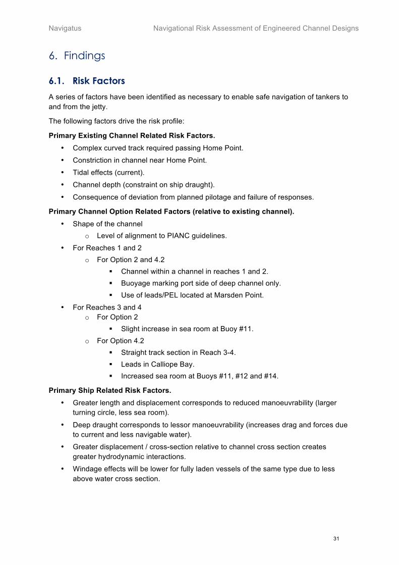
6.1. Risk Factors
A series of factors have been identified as necessary to enable safe navigation of tankers to and from the jetty.
The following factors drive the risk profile:
Primary Existing Channel Related Risk Factors. • Complex curved track required passing Home Point.
• Constriction in channel near Home Point.
• Tidal effects (current).
• Channel depth (constraint on ship draught).
• Consequence of deviation from planned pilotage and failure of responses.
Primary Channel Option Related Factors (relative to existing channel). • Shape of the channel
o Level of alignment to PIANC guidelines.
• For Reaches 1 and 2 o For Option 2 and 4.2
! Channel within a channel in reaches 1 and 2. ! Buoyage marking port side of deep channel only. ! Use of leads/PEL located at Marsden Point.
• For Reaches 3 and 4 o For Option 2
! Slight increase in sea room at Buoy #11. o For Option 4.2
! Straight track section in Reach 3-4. ! Leads in Calliope Bay. ! Increased sea room at Buoys #11, #12 and #14.
Primary Ship Related Risk Factors. • Greater length and displacement corresponds to reduced manoeuvrability (larger
turning circle, less sea room).
• Deep draught corresponds to lessor manoeuvrability (increases drag and forces due to current and less navigable water).
• Greater displacement / cross-section relative to channel cross section creates greater hydrodynamic interactions.
• Windage effects will be lower for fully laden vessels of the same type due to less above water cross section.

Navigational Risk Assessment of Engineered Channel Designs Navigatus
32
6.2. Risk Profile - Channels
As this risk assessment is qualitative and aims to identify the relative change of risk profile between channel options the overall risk profile is described visually in a series of tables and charts formatted to describe risk in relative terms. As noted earlier in section 5.2, a range of operational measures has been assumed to have been implemented as pre-requisites to the use of the revised channel.
6.2.1. Graphical Risk Profile
The graphical risk profiles below use the following key: For PIANC (as used in Figure 6)
• Blue: Optimum – Ideal under both operating and extreme conditions, no issues encountered.
• Green: Adequate – Very good under operating conditions, manageable under extreme conditions.
• Orange: Marginal – Adequate under operating conditions but poor under extreme conditions.
• Red: Inadequate – Poor under both operating and extreme conditions, may be considered unacceptable from a navigational risk perspective.
For Consequence (as used in Figure 8): • Red: Rock, Higher • Orange: Sand, Medium • Yellow: Jetty, Lower
The coloured arrows indicate the change in threat risk. Red arrows ( ) indicate an increased level while green arrows ( ) indicate a decreased risk. A dash (-) indicates the current level or no effect on the current level of risk. The degree of change in risk is indicated by the number of arrows; with the ratio of the number of arrows approximating to the relative change. It is emphasised that these are ‘ordinal’ scales and so do not have a strict arithmetic relationship. However, in general terms, a risk change indicated by two arrows can be considered to be indicatively twice the change indicated by one arrow.
Throughout these risk profiles ‘Existing Tankers’ are defined as the Aframax tankers and part laden Suezmax tankers with a maximum draught of 14.7m currently visiting Marsden Point. “Proposed Tankers’ are fully laden Suezmax tankers with a maximum draught 16.6m. N/A indicates that fully laden Suezmax tankers cannot transit the existing channel.
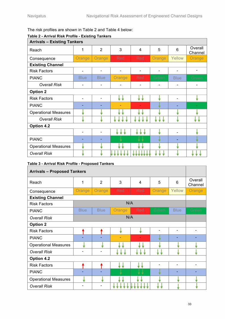
Navigatus Navigational Risk Assessment of Engineered Channel Designs
33
The risk profiles are shown in Table 2 and Table 4 below: Table 2 - Arrival Risk Profile - Existing Tankers Arrivals – Existing Tankers
Reach 1 2 3 4 5 6 Overall Channel
Consequence Orange Orange Red Red Orange Yellow Orange Existing Channel Risk Factors - - - - - - -
PIANC Blue Blue Orange Red Green Blue Green Overall Risk - - - - - - -
Option 2 Risk Factors - -
-
PIANC - - - -
- -
Operational Measures
Overall Risk
Option 4.2 - -
-
PIANC - -
-
Operational Measures
Overall Risk
Table 3 - Arrival Risk Profile - Proposed Tankers
Arrivals – Proposed Tankers
Reach 1 2 3 4 5 6 Overall Channel
Consequence Orange Orange Red Red Orange Yellow Orange
Existing Channel Risk Factors N/A
PIANC Blue Blue Orange Red Green Blue Green
Overall Risk N/A
Option 2 Risk Factors
- - -
PIANC - - - -
- -
Operational Measures
Overall Risk - -
Option 4.2 Risk Factors
- - -
PIANC - -
- -
Operational Measures
Overall Risk - -

Navigational Risk Assessment of Engineered Channel Designs Navigatus
34
Table 4 - Departure Risk Profile
Departures – Existing Tankers Reach 1 2 3 4 5 6 Overall
Channel Consequence Orange Orange Red Red Orange Yellow Orange
Existing Channel Risk Factors - - - - - - -
PIANC Blue Blue Orange Red Green Blue Orange
Overall Risk - - - - - - -
Option 2 Risk Factors - -
-
PIANC - - - -
- -
Operational Measures
Overall Risk
Option 4.2 Risk Factors - -
-
PIANC - -
-
Operational Measures
Overall Risk
6.2.2. Visual Risk Profiles
The case of the proposed fully laden Suezmax tankers arrival is of particular interest as this is the focus of the Assessment of Effects on the Environment (AEE) appraisal. The increased displacement and draught of the fully laden Suezmax tankers and the ‘channel within a channel’ in Reach 1 do act to increase risk compared to the current situation. However, the overall reduction in risk due to the simpler navigational passage made possible by the channel design itself and improved operating procedures, is notably greater. This combination is illustrated in Figure 9 below. It can be seen that, enables greatly reduced risk and, given the use of the required operational procedures, the overall risk is lower than that for the existing channel and procedures, with the channel design of Option 4.2 resulting in a lower level of risk than that possible given channel design Option 2.
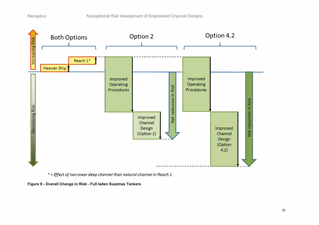
Navigatus Navigational Risk Assessment of Engineered Channel Designs
35
Figure 9 - Overall Change in Risk - Full laden Suezmax Tankers

Navigational Risk Assessment of Engineered Channel Designs Navigatus
36
6.3. Overall Risk Assessment - Channels
The overall risk assessment assumes the operational measures detailed in Section 5.2 have been implemented. It shows the relative risk of utilisation of the engineered channels against use of the existing channel (noting that fully laden Suezmax tankers are unable to use the existing channel due to their draught). The overall risk assessment is shown in Table 5 below. Table 5 – Overall Risk Assessment Channel Reach
Existing Option 2 Option 4.2
Arrival
1-2 Existing Tankers - ! ! Proposed Tankers N/A - -
3-4 Existing Tankers - !!!! !!!!!!
Proposed Tankers N/A !!! !!!!!
5-6 Existing Tankers - !! !!!
Proposed Tankers N/A ! ! Departure
5-6 All Tankers - !! !!
3-4 All Tankers - !!! !!!!!
1-2 All Tankers - ! !
All Existing Tankers 0 -13 -18 Proposed Tankers24 N/A -10 -14
The coloured arrows indicate the change-in-risk. Red arrows (") indicate increased risk while green arrows (!) indicate a similar decreased risk. The number of arrows indicates the degree of change-of-risk; more arrows indicate a greater degree of change. A dash (-) indicates no change from present. To aid clarity, the final tally is indicated numerically (e.g.-6). It is important to note that this figure forms an ‘interval‘ scale25 and so are only indicative of relative risk and where a value of zero represents the current level of risk.
24 It is noted that there are no plans to depart with fully laden Suezmax tankers. Therefore the proposed tankers are counted as if existing tankers for departure. 25 Interval scale is described in SA/SNZ HB 436:2013 Risk Management Guidelines. Table 4.

Navigatus Navigational Risk Assessment of Engineered Channel Designs
37
6.4. Risk Assessment – Disposal Sites
As noted before, given the very limited change in depth and bottom profile from disposal activity, and that the effect on wave height is predicted to be less than 10cm under the most pessimistic conditions, it is self-evident that the effect on safe navigation of surface vessels of any kind while simply transiting the area will be nil.
It is conceivable that vessels involved in bottom trawling could be affected. However, given the natural behaviour of sand and that trawls are designed and operated to handle the inevitable natural undulations of the sea floor, it is difficult to conceive of an issue. This aspect can be expected to be further mitigated by the correct chart amendments to show the disposal sites.
Given it is also assumed that the operation of the dredger and spoil barges will be undertaken following proper professional maritime practice, the operations themselves will not materially effect the safe navigation of other vessels.
It is therefore assessed that the risk to the navigation of other vessels from the disposal sites and the associated activity is less than incidental.
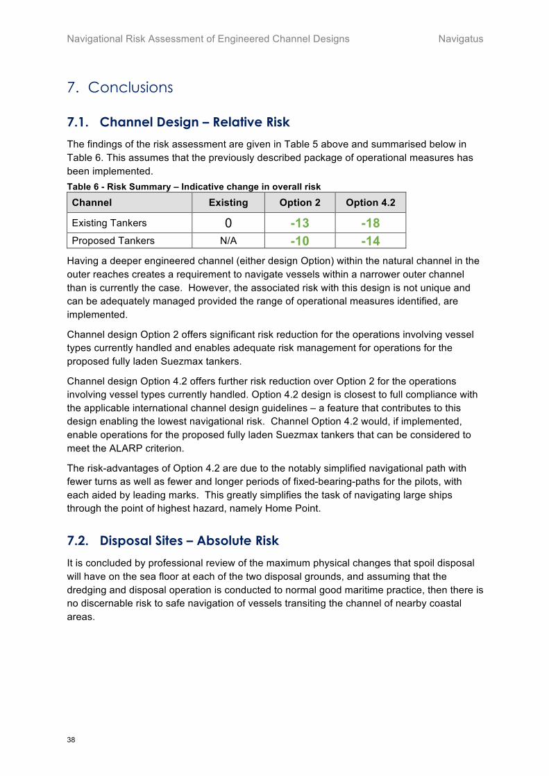
Navigational Risk Assessment of Engineered Channel Designs Navigatus
38
7. Conclusions
7.1. Channel Design – Relative Risk
The findings of the risk assessment are given in Table 5 above and summarised below in Table 6. This assumes that the previously described package of operational measures has been implemented. Table 6 - Risk Summary – Indicative change in overall risk
Channel Existing Option 2 Option 4.2
Existing Tankers 0 -13 -18 Proposed Tankers N/A -10 -14
Having a deeper engineered channel (either design Option) within the natural channel in the outer reaches creates a requirement to navigate vessels within a narrower outer channel than is currently the case. However, the associated risk with this design is not unique and can be adequately managed provided the range of operational measures identified, are implemented.
Channel design Option 2 offers significant risk reduction for the operations involving vessel types currently handled and enables adequate risk management for operations for the proposed fully laden Suezmax tankers.
Channel design Option 4.2 offers further risk reduction over Option 2 for the operations involving vessel types currently handled. Option 4.2 design is closest to full compliance with the applicable international channel design guidelines – a feature that contributes to this design enabling the lowest navigational risk. Channel Option 4.2 would, if implemented, enable operations for the proposed fully laden Suezmax tankers that can be considered to meet the ALARP criterion.
The risk-advantages of Option 4.2 are due to the notably simplified navigational path with fewer turns as well as fewer and longer periods of fixed-bearing-paths for the pilots, with each aided by leading marks. This greatly simplifies the task of navigating large ships through the point of highest hazard, namely Home Point.
7.2. Disposal Sites – Absolute Risk
It is concluded by professional review of the maximum physical changes that spoil disposal will have on the sea floor at each of the two disposal grounds, and assuming that the dredging and disposal operation is conducted to normal good maritime practice, then there is no discernable risk to safe navigation of vessels transiting the channel of nearby coastal areas.