Embed Size (px)
DESCRIPTION
Breasting, Mooring Dolphin, & Main Jetty
Citation preview

3 of 503 of 503 of 50
DOC. NO. :RFCC-A-64-CV-CS-028-A
REV. NO. : 2
PAGE :
Page1. 4
1.1. 41.2. 41.3. 41.4. 5
2. 62.1. 62.2. 6
3. 73.1. 73.2. 83.3. 193.4. 223.5. 243.6. 263.7. 283.8. 283.9. 29
3.10. 304. 32
4.1. 324.2. 324.3. 344.4. 344.5. 344.6. 344.7. 34
5. 355.1. 355.2. 355.3. 425.4. 445.5. 32
I LAY OUT JETTY 64 MODIFICATION BASED ON SN#24IIIIIIVVVIVII
DIMENSION OF MOORING DOLPHIN
DIMENSION OF MAIN JETTY
CALCULATION FOR THE STEEL REINFORCEMENT BETWEEN PILE CAP AND STEEL PIPE PILE
LOCATION OF JETTY 64
DATA BORE HOLE OF JETTY 64 AREA
CHECK STRESS RATIO & DEFLECTIONCORROSION ANALYSIS
MAIN JETTY
LOAD MAIN JETTY
REINFORCING CONCRETE DESIGN
DIMENSION OF SHIPTIDAL RANGEBREASTING DOLPHINDIMENSION OF BREASTING DOLPHIN
MOORING DOLPHIN
3D VIEW MAIN JETTY, MOORING & BREASTING DOLPHIN
LOAD MOORING DOLPHIN
Cilacap Resid Fluid Catalytic Cracking (RFCC) Project
PT. PERTAMINA (PERSERO)Calculation For Loading Platform
Mooring & Breasting Dolphin
TABLE OF CONTENT
SCOPE OF WORKGENERAL
PRIMARY LOAD BREASTING
REFERENCEBASIC ASSUMPTIONDESIGN CRITERIADATA INFORMATION
FOUNDATION DESIGN
LOAD COMBINATION
INPUT CALCULATION STAADPRO (Breasting Dolphin, Mooring Dolphin & Main Jetty)GENERAL ATTACHMENT
CHECK STRESS RATIO & DEFLECTION
LOAD COMBINATION
LOAD COMBINATIONCHECK STRESS RATIO & DEFLECTIONCHECK CORROSION ANALYSISMARINE GROWTH ANALYSIS
CORROSION ANALYSIS
DISTANCE BETWEEN THE FENDERREINFORCING CONCRETE DESIGN
FOUNDATION DESIGN
DESIGN DIMENSION OF FENDER
ATTACHMENT
4 of 504 of 504 of 50
DOC. NO. :RFCC-A-64-CV-CS-028-A
REV. NO. : 2
PAGE :
Cilacap Resid Fluid Catalytic Cracking (RFCC) Project
PT. PERTAMINA (PERSERO)Calculation For Loading Platform
Mooring & Breasting Dolphin
1. G E N E R A L
1.1. SCOPE OF WORKThis calculation is made to determine the detailed design of infrastructure offshore Jetty 64 Modification. It consists of Mooring Dolphin ,Breasting Dolphin & Main Jetty for Resid Fluid Catalytic Cracking (RFCC)Project Pertamina (Persero), Cilacap Central Java, Indonesia.
1.2. REFERENCE
1.2.1 DOCUMENT REFERENCEThe listed below documents are information of lay out drawings which are utilized asreference for this document :- Suplementary Notice Cilacap Resid fluid Catalytic Cracking (RFCC) Project, Number SN-024.- Report on Modification of Jetty#64 & #68, Doc No: 000-T7605/001- Soil Investigation Cilacap RFCC Project for Jetty Area at Pertamina RU-IV Cilacap-Central Java. Job No:2724.- Design Specification for Civil and Structural Engineering Specification for Design Load (RFCC-C-CV-SP-001) Engineering Specification for Reinforced Concrete Structure Reinf (RFCC-C-CV-SP-003) Engineering Specification for Concrete Foundation (RFCC-C-CV-SP-004) Specification for Marine Concrete and Steel Piling (RFCC-A-CV-SP-002)
1.2.2 CODE & STANDARDThe listed below documents are applicable codes, to be used to support this calculation.- OCDI, Technical Standards and Commentaries for Port and Harbour Facilities in 'Japan,2002- BS 6349-4, Maritime Structure Part4: Code of practice for design of fendering & Mooring systems, 1994- OCIMF publication: "Guide Line & Recommendations for the safe mooring of large ship at pier & sea island"- API-RP 2A, "Recommended Practice for Plannig, Designing, Contructing of Fixed Offshore Patform".- Building Code Requirements in Reinforced Concrete (ACI-318M-02)- Standar Nasional Indonesia Design Method of Earthquake Resistance for Buildigs (SNI 03-1726-2002)- Minimum Design Loads for Buildings and others structure (ASCE/SEI 7-05)- AISC, "Manual of Steel Construction: Allowable Stress Design 9th edition"
1.3. BASIC ASSUMPTIONS
- For member design loading combinations refering to Building Code Requirements in Reinforced Concrete (ACI-318M) are applied. In the permanent condition, stresses due to external load shall not more than allowable stresses.But for temporary condition allowable stresses can be increased by 33,33%.

5 of 505 of 505 of 50
DOC. NO. :RFCC-A-64-CV-CS-028-A
REV. NO. : 2
PAGE :
Cilacap Resid Fluid Catalytic Cracking (RFCC) Project
PT. PERTAMINA (PERSERO)Calculation For Loading Platform
Mooring & Breasting Dolphin
1.4. DESIGN CRITERIA
1.4.1 MATERIALClassification and engineering properties of major material to be used for this Jetty 64 structureare listed below :
Concrete for structure (fc') = 310 kg/cm2
Cement: Portland Cement Type 1 as per ASTM C150 or equivalent and plus fly ash.Agregat size : 20mm (Min). ASTM C33 or equivalent.
4000 kg/cm2
= 2460.7 kg/cm2 35000 psi= 4218.4 kg/cm2 60000 psi
Structural Steel Shapes and Plates ASTM A36 := 2531.1 kg/cm2 36000 psi= 4218.4 kg/cm2 60000 psi
Structural Steel pipes ASTM A53 : == 2460.7 kg/cm2 35000 psi= 4218.4 kg/cm2 60000 psi
1.4.2 LOADING
PRIMARY LOAD
- DL (Dead Load)- LL (Live Load)- CX (Current Load - X)- CZ (Current Load - Z)- WX (Wave Load - X)- WZ (Wave Load - Z)- EX (Seismic Load - X)- EZ (Sesimic Load - Z)- Fe (Fender Load)- B (Bollard Load)
Yield strengthTensile strength
Ref: Engineering Specification For Reincforced Concrete Structure(Ref: RFCC-C-CV-SP-003)
(ASTM A252 Grade2) Ref :Specification for Marine Concrete and Steel Piling (RFCC-A-CV-SP-002)
- Concrete:
Reference: OCIMF, Table 31F-3-13 Service or ASD load factors for Load Combination
- Reinforcement: ASTM A615M Grade 60, JIS G3122 SD390, or equivalent
-Steel Pipe Pile:
-Steel :
Tensile strength
Yield strengthTensile strength
Yield strength

6 of 506 of 506 of 50
DOC. NO. :RFCC-A-64-CV-CS-028-A
REV. NO. : 2
PAGE :
Cilacap Resid Fluid Catalytic Cracking (RFCC) Project
PT. PERTAMINA (PERSERO)Calculation For Loading Platform
Mooring & Breasting Dolphin
LC for check stress ratio
LOADING PLATFORM/ DOLPHIN CONDITION:LC 1 = DL + LL + WAVE LOAD DIR X + CURRENT LOAD DIR X + BOLLARD + FENDERLC 2 = DL + LL + WAVE LOAD DIR Z + CURRENT LOAD DIR Z + BOLLARD + FENDER
EARTHQUAKE CONDITION:LC3 = 1.35 DL + 0.7 seismic load-XLC4 = 1.35 DL + 0.7 seismic load-Z
Earthquake Load = DL + 0.25 LL
LC for check reinforcement
LOADING PLATFORM/ DOLPHIN CONDITION:LC 5 = 1.4DL+1.7LL+1.3(WAVE LOAD DIR X + CURRENT LOAD DIR X)+1.3MOORING & BREASTING LOALC 6 = 1.4DL+1.7LL+1.3(WAVE LOAD DIR Z + CURRENT LOAD DIR Z)+1.3MOORING & BREASTING LOAD
Reference: OCIMF, Table 31F-3-13 Service or ASD load factors for Load
Reference: OCIMF, Table 31F-3-12 Service or LRFD load factors for Load
7 of 507 of 507 of 50
DOC. NO. :RFCC-A-64-CV-CS-028-A
REV. NO. : 2
PAGE :
Cilacap Resid Fluid Catalytic Cracking (RFCC) Project
PT. PERTAMINA (PERSERO)Calculation For Loading Platform
Mooring & Breasting Dolphin
2. DATA INFORMATION
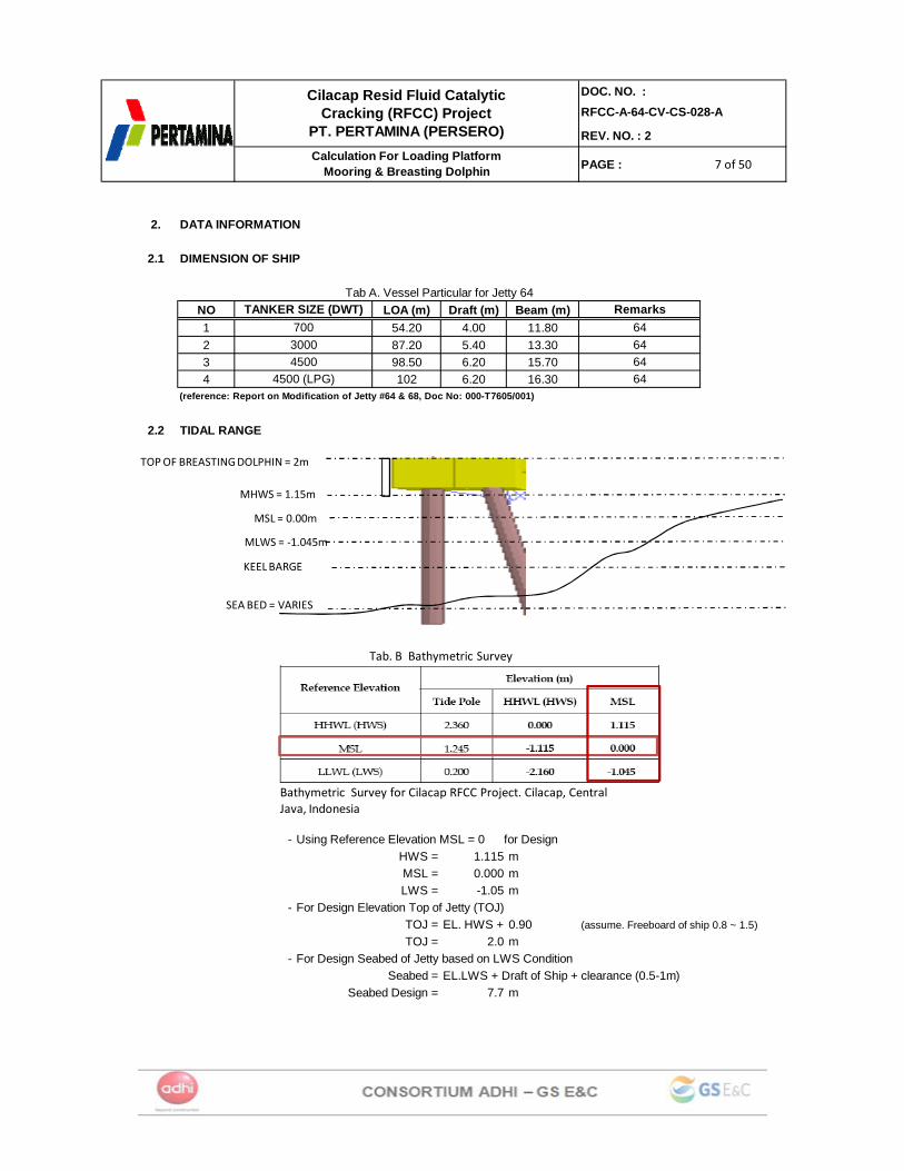
2.1 DIMENSION OF SHIP
NO LOA (m) Draft (m) Beam (m)1 54.20 4.00 11.802 87.20 5.40 13.303 98.50 6.20 15.704 102 6.20 16.30
(reference: Report on Modification of Jetty #64 & 68, Doc No: 000-T7605/001)
2.2 TIDAL RANGE
- Using Reference Elevation MSL = 0 for DesignHWS = 1.115 mMSL = 0.000 mLWS = -1.05 m
- For Design Elevation Top of Jetty (TOJ)TOJ = EL. HWS + 0.90 (assume. Freeboard of ship 0.8 ~ 1.5)TOJ = 2.0 m
- For Design Seabed of Jetty based on LWS ConditionSeabed = EL.LWS + Draft of Ship + clearance (0.5-1m)
Seabed Design = 7.7 m
Tab A. Vessel Particular for Jetty 64
64
Remarks700
TANKER SIZE (DWT)
644500 64
643000
4500 (LPG)
SEA BED = VARIES
KEELBARGE
MLWS = ‐1.045m
MSL = 0.00m
MHWS = 1.15m
TOPOF BREASTING DOLPHIN = 2m
Bathymetric Survey for Cilacap RFCC Project. Cilacap, Central Java, Indonesia
Tab. B Bathymetric Survey
8 of 508 of 508 of 50
DOC. NO. :RFCC-A-64-CV-CS-028-A
REV. NO. : 2
PAGE :
Cilacap Resid Fluid Catalytic Cracking (RFCC) Project
PT. PERTAMINA (PERSERO)Calculation For Loading Platform
Mooring & Breasting Dolphin
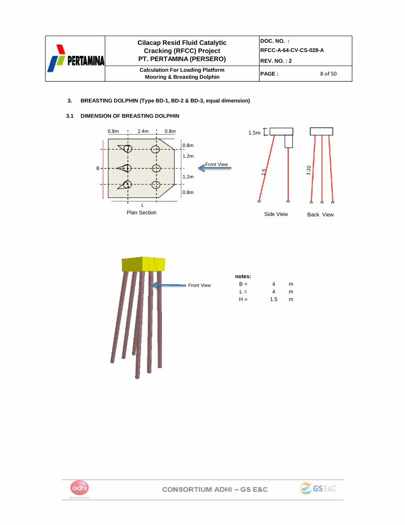
3. BREASTING DOLPHIN (Type BD-1, BD-2 & BD-3, equal dimension)
3.1 DIMENSION OF BREASTING DOLPHIN
notes:B = 4 mL = 4 mH = 1.5 m
2.4m 0.8m0.8m
1.2m
1.2m
0.8m
0.8m
Plan Section Back View
Front View
Side View
1.5m
Front View
B
L
9 of 509 of 509 of 50
DOC. NO. :RFCC-A-64-CV-CS-028-A
REV. NO. : 2
PAGE :
Cilacap Resid Fluid Catalytic Cracking (RFCC) Project
PT. PERTAMINA (PERSERO)Calculation For Loading Platform
Mooring & Breasting Dolphin
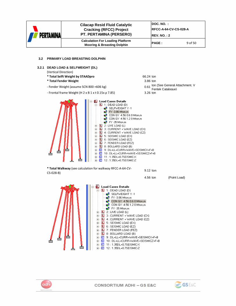
3.2 PRIMARY LOAD BREASTING DOLPHIN
3.2.1 DEAD LOAD & SELFWEIGHT (DL)(Vertical Direction)
66.24 ton3.86 ton
‐ Fender Weight (assume SCN 800 =606 kg) 0.61
‐ Frontal frame Weight (H 2 x B 1 x t 0.15x ρ 7.85) 3.26 ton
9.12 ton
4.56 ton (Point Load)
* Total Selft Weight by STAADpro
* Total Walkway (see calculation for walkway RFCC‐A‐64‐CV‐CS‐028‐B)
ton (See General Attachment. V Fentek Catalogue)
* Total Fender Weight
10 of 5010 of 5010 of 50
DOC. NO. :RFCC-A-64-CV-CS-028-A
REV. NO. : 2
PAGE :
Cilacap Resid Fluid Catalytic Cracking (RFCC) Project
PT. PERTAMINA (PERSERO)Calculation For Loading Platform
Mooring & Breasting Dolphin
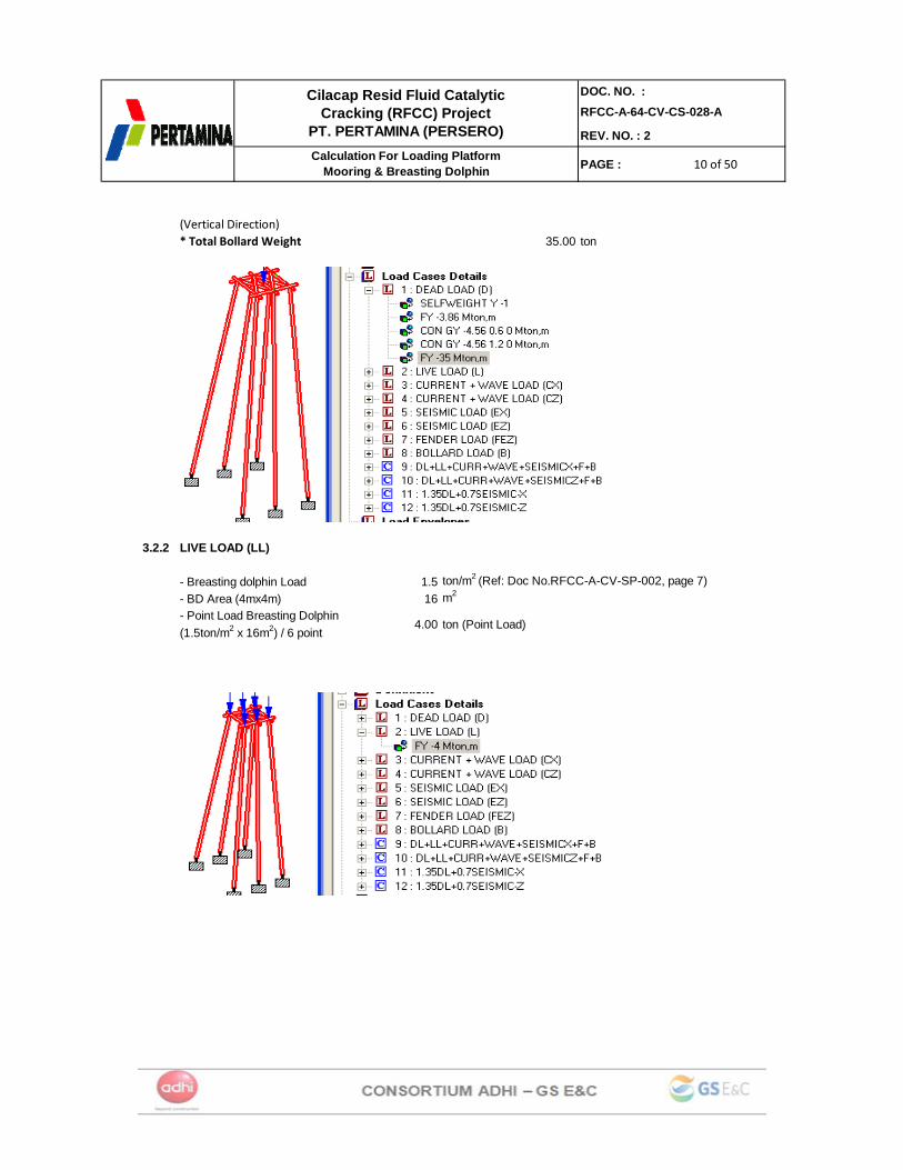
(Vertical Direction)35.00 ton
3.2.2 LIVE LOAD (LL)
- Breasting dolphin Load 1.5 ton/m2 (Ref: Doc No.RFCC-A-CV-SP-002, page 7)- BD Area (4mx4m) 16 m2
4.00 ton (Point Load)- Point Load Breasting Dolphin (1.5ton/m2 x 16m2) / 6 point
* Total Bollard Weight

11 of 5011 of 5011 of 50
DOC. NO. :RFCC-A-64-CV-CS-028-A
REV. NO. : 2
PAGE :
Cilacap Resid Fluid Catalytic Cracking (RFCC) Project
PT. PERTAMINA (PERSERO)Calculation For Loading Platform
Mooring & Breasting Dolphin
3.2.3 SEISMIC LOADSEISMIC DESIGN (S) = DEAD LOAD + 0.25 LIVE LOAD
= 115.66 ton= 19.28 ton/node
The site is covered by Zone 4 with the base ground acceleration 0.20g (SNI-1726-2002)Total base shear load force shall be calculated using following formula :
V = Cd x Wt = (C1 x I / R) x Wtwhere :
V = total base shear load (ton)
Soil type = Soft soil(SE) (Tab.13, Page24, Soil Invest)
Z = zone factor (for zone 4) = 0.2 (SNI-1726-2002, Tab.5, Page 19)I = seismic importance factor = 1.5 (SNI-1726-2002, Tab.1, Page12)
C1 = 0.85 (SNI-1726-2002,Tab.6.Page21)
R = numerical coefficient = 8.5 (SNI-1726-2002,Tab.3.Page16) (for Concrete OMRF = Ordinary Moment Resisting Frame)
Fx = (V-Ft).wi.hiΣ wi.hi
note N Node fy (ton) wi (ton) hi (m) wi*hi (tonm) wi*hi/S(wi*hi)
V Fx (ton)
BD 6 19.28 19.28 17.62 339.66 0.167 17.35 2.89115.66 2037.96
= seismic coefficient (from spectrum diagram)
12 of 5012 of 5012 of 50
DOC. NO. :RFCC-A-64-CV-CS-028-A
REV. NO. : 2
PAGE :
Cilacap Resid Fluid Catalytic Cracking (RFCC) Project
PT. PERTAMINA (PERSERO)Calculation For Loading Platform
Mooring & Breasting Dolphin
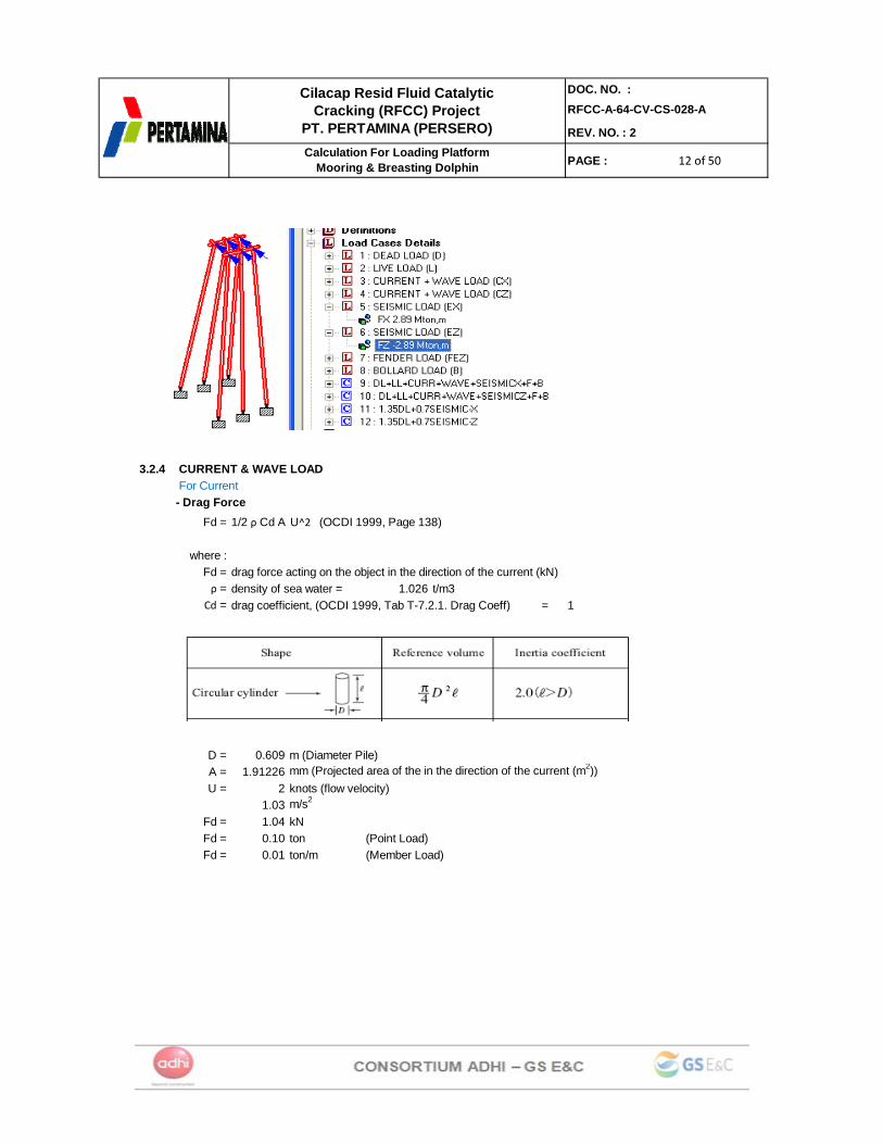
3.2.4 CURRENT & WAVE LOAD For Current- Drag Force
Fd =
where :Fd = drag force acting on the object in the direction of the current (kN)ρ = density of sea water = 1.026 t/m3
Cd = drag coefficient, (OCDI 1999, Tab T-7.2.1. Drag Coeff) = 1
D = 0.609 m (Diameter Pile)A = 1.91226 mm (Projected area of the in the direction of the current (m2))U = 2 knots (flow velocity)
1.03 m/s2
Fd = 1.04 kNFd = 0.10 ton (Point Load)Fd = 0.01 ton/m (Member Load)
1/2 ρ Cd A U^2 (OCDI 1999, Page 138)

13 of 5013 of 5013 of 50
DOC. NO. :RFCC-A-64-CV-CS-028-A
REV. NO. : 2
PAGE :
Cilacap Resid Fluid Catalytic Cracking (RFCC) Project
PT. PERTAMINA (PERSERO)Calculation For Loading Platform
Mooring & Breasting Dolphin
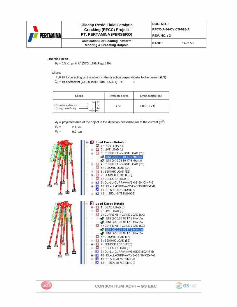
- Inertia ForceFL = 1/2 CL ρ0 AL U
2 (OCDI 1999, Page 139)
where:FL= lift force acting on the object in the direction perpendicular to the current (kN)
CL = lift coefficient (OCDI 1999, Tab. T-5.4.1) = 2
AL = projected area of the object in the direction perpendicular to the current (m2)FL = 2.1 kNFL = 0.2 ton (Point Load)FL = 0.03 ton/m (Member Load)
For Wave:- Drag Force
Fd =
where :Fd = drag force acting on the object in the direction of the current (kN)ρ = density of sea water = 1.026 t/m3
Cd = drag coefficient, (OCDI 1999, Tab T-7.2.1. Drag Coeff) = 1
D = 0.609 m (Diameter Pile)A = 1.91226 mm (Projected area of the in the direction of the current (m2))U = 2 knots (wave velocity)
1.03 m/s2
Fd = 1.04 kNFd = 0.10 ton
1/2 ρ Cd A U^2 (OCDI 1999, Page 138)
14 of 5014 of 5014 of 50
DOC. NO. :RFCC-A-64-CV-CS-028-A
REV. NO. : 2
PAGE :
Cilacap Resid Fluid Catalytic Cracking (RFCC) Project
PT. PERTAMINA (PERSERO)Calculation For Loading Platform
Mooring & Breasting Dolphin
- Inertia ForceFL = 1/2 CL ρ0 AL U
2 (OCDI 1999, Page 139)
where:FL= lift force acting on the object in the direction perpendicular to the current (kN)
CL = lift coefficient (OCDI 1999, Tab. T-5.4.1) = 2
AL = projected area of the object in the direction perpendicular to the current (m2)FL = 2.1 kNFL = 0.2 ton
15 of 5015 of 5015 of 50
DOC. NO. :RFCC-A-64-CV-CS-028-A
REV. NO. : 2
PAGE :
Cilacap Resid Fluid Catalytic Cracking (RFCC) Project
PT. PERTAMINA (PERSERO)Calculation For Loading Platform
Mooring & Breasting Dolphin
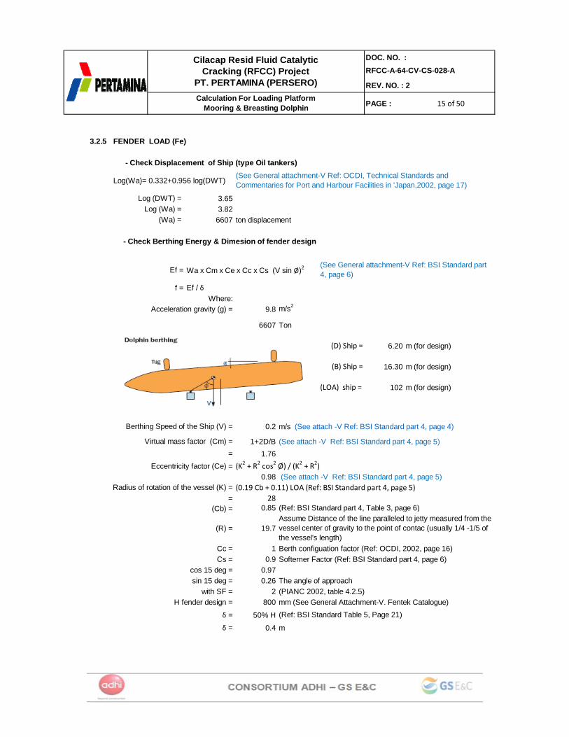
3.2.5 FENDER LOAD (Fe)
- Check Displacement of Ship (type Oil tankers)
Log(Wa)= 0.332+0.956 log(DWT)
3.653.82
6607 ton displacement
- Check Berthing Energy & Dimesion of fender design
Ef = Wa x Cm x Ce x Cc x Cs (V sin Ø)2
f = Ef / δ Where:
9.8 m/s2
6607 Ton
(D) Ship = 6.20 m (for design)
(B) Ship = 16.30 m (for design)
(LOA) ship = 102 m (for design)
0.2 m/s (See attach -V Ref: BSI Standard part 4, page 4)
1+2D/B (See attach -V Ref: BSI Standard part 4, page 5)1.76
(K2 + R2 cos2 Ø) / (K2 + R2)0.98 (See attach -V Ref: BSI Standard part 4, page 5)
(0.19 Cb + 0.11) LOA (Ref: BSI Standard part 4, page 5)= 28
(Cb) = 0.85 (Ref: BSI Standard part 4, Table 3, page 6)
(R) = 19.7
Cc = 1 Berth configuation factor (Ref: OCDI, 2002, page 16)Cs = 0.9 Softerner Factor (Ref: BSI Standard part 4, page 6)
cos 15 deg = 0.97sin 15 deg = 0.26 The angle of approach
with SF = 2 (PIANC 2002, table 4.2.5)H fender design = 800 mm (See General Attachment-V. Fentek Catalogue)
δ = 50% Hδ = 0.4 m
Assume Distance of the line paralleled to jetty measured from the vessel center of gravity to the point of contac (usually 1/4 -1/5 of the vessel's length)
=
Log (Wa) = (Wa) =
Berthing Speed of the Ship (V) =
(Ref: BSI Standard Table 5, Page 21)
Acceleration gravity (g) =
(See General attachment-V Ref: BSI Standard part 4, page 6)
(See General attachment-V Ref: OCDI, Technical Standards and Commentaries for Port and Harbour Facilities in 'Japan,2002, page 17)
Eccentricity factor (Ce) =
Radius of rotation of the vessel (K) =
Log (DWT) =
Virtual mass factor (Cm) =
16 of 5016 of 5016 of 50
DOC. NO. :RFCC-A-64-CV-CS-028-A
REV. NO. : 2
PAGE :
Cilacap Resid Fluid Catalytic Cracking (RFCC) Project
PT. PERTAMINA (PERSERO)Calculation For Loading Platform
Mooring & Breasting Dolphin
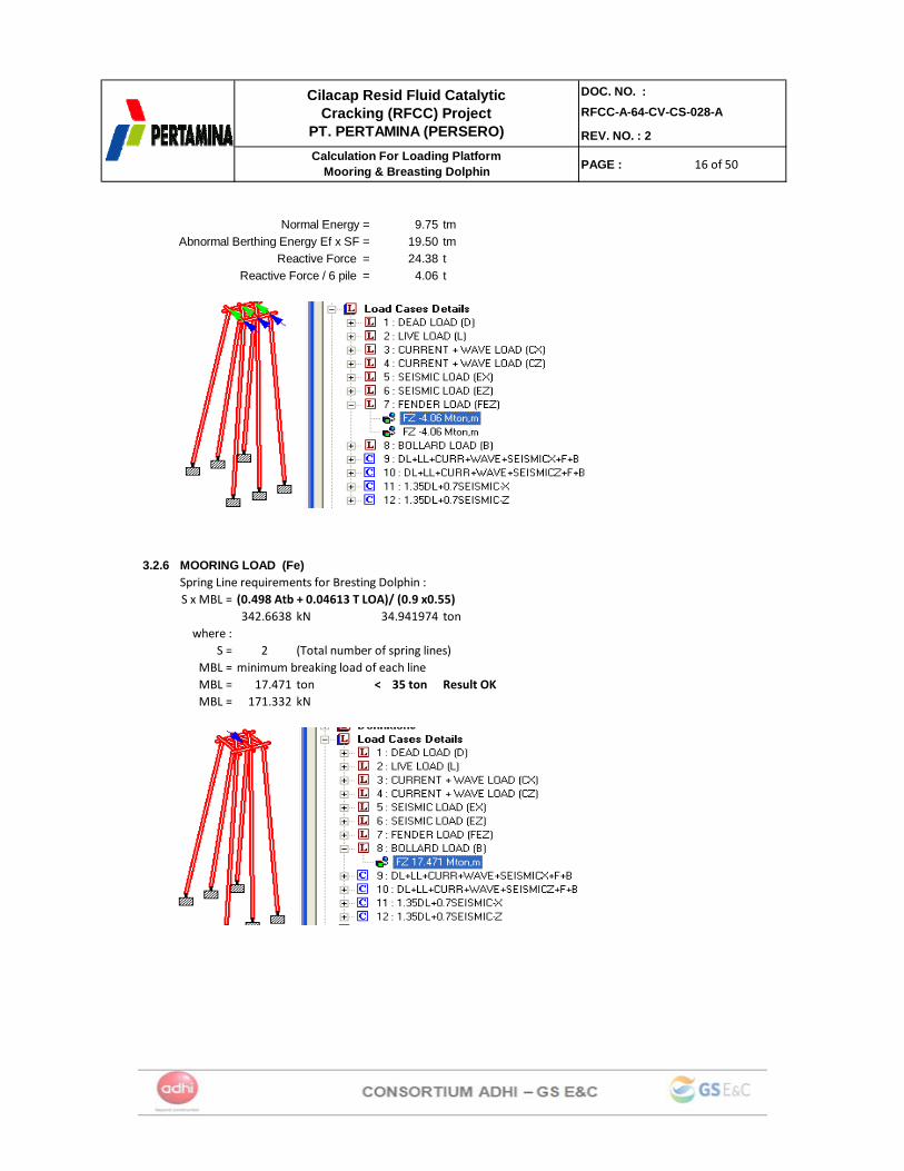
Normal Energy = 9.75 tmAbnormal Berthing Energy Ef x SF = 19.50 tm
Reactive Force = 24.38 t Reactive Force / 6 pile = 4.06 t
3.2.6 MOORING LOAD (Fe)Spring Line requirements for Bresting Dolphin :S x MBL = (0.498 Atb + 0.04613 T LOA)/ (0.9 x0.55)
342.6638 kN 34.941974 tonwhere :
S = 2 (Total number of spring lines)MBL = minimum breaking load of each lineMBL = 17.471 ton < 35 ton Result OKMBL = 171.332 kN
17 of 5017 of 5017 of 50
DOC. NO. :RFCC-A-64-CV-CS-028-A
REV. NO. : 2
PAGE :
Cilacap Resid Fluid Catalytic Cracking (RFCC) Project
PT. PERTAMINA (PERSERO)Calculation For Loading Platform
Mooring & Breasting Dolphin
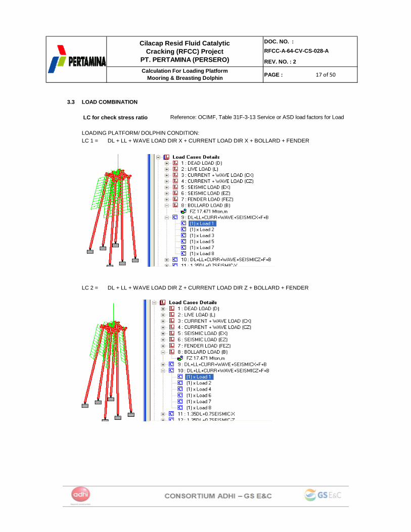
3.3 LOAD COMBINATION
LC for check stress ratio
LOADING PLATFORM/ DOLPHIN CONDITION:LC 1 = DL + LL + WAVE LOAD DIR X + CURRENT LOAD DIR X + BOLLARD + FENDER
LC 2 = DL + LL + WAVE LOAD DIR Z + CURRENT LOAD DIR Z + BOLLARD + FENDER
Reference: OCIMF, Table 31F-3-13 Service or ASD load factors for Load
18 of 5018 of 5018 of 50
DOC. NO. :RFCC-A-64-CV-CS-028-A
REV. NO. : 2
PAGE :
Cilacap Resid Fluid Catalytic Cracking (RFCC) Project
PT. PERTAMINA (PERSERO)Calculation For Loading Platform
Mooring & Breasting Dolphin
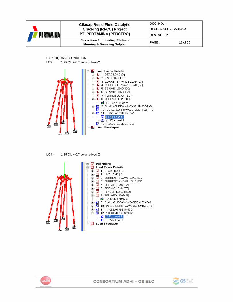
EARTHQUAKE CONDITION:LC3 = 1.35 DL + 0.7 seismic load-X
LC4 = 1.35 DL + 0.7 seismic load-Z
19 of 5019 of 5019 of 50
DOC. NO. :RFCC-A-64-CV-CS-028-A
REV. NO. : 2
PAGE :
Cilacap Resid Fluid Catalytic Cracking (RFCC) Project
PT. PERTAMINA (PERSERO)Calculation For Loading Platform
Mooring & Breasting Dolphin
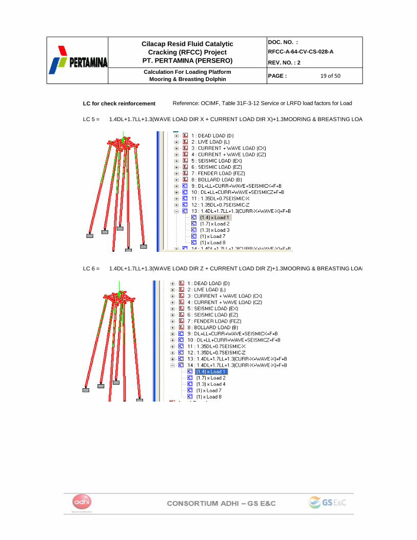
LC for check reinforcement
LC 5 = 1.4DL+1.7LL+1.3(WAVE LOAD DIR X + CURRENT LOAD DIR X)+1.3MOORING & BREASTING LOA
LC 6 = 1.4DL+1.7LL+1.3(WAVE LOAD DIR Z + CURRENT LOAD DIR Z)+1.3MOORING & BREASTING LOAD
Reference: OCIMF, Table 31F-3-12 Service or LRFD load factors for Load

20 of 5020 of 5020 of 50
DOC. NO. :RFCC-A-64-CV-CS-028-A
REV. NO. : 2
PAGE :
Cilacap Resid Fluid Catalytic Cracking (RFCC) Project
PT. PERTAMINA (PERSERO)Calculation For Loading Platform
Mooring & Breasting Dolphin
3.4. CHECK STRESS RATIO & DEFLECTION
Check Ratio maximum 0.466 < Allowable Ratio 1

21 of 5021 of 5021 of 50
DOC. NO. :RFCC-A-64-CV-CS-028-A
REV. NO. : 2
PAGE :
Cilacap Resid Fluid Catalytic Cracking (RFCC) Project
PT. PERTAMINA (PERSERO)Calculation For Loading Platform
Mooring & Breasting Dolphin
Deflection Check
Node L/C X-Trans mm Y-Trans mm
Z-Trans mm
Absolute mm
X-Rotan rad
Y-Rotan rad Z-Rotan rad
15 9 27.41 -3.33 7.33 28.57 0.00 0.00 0.0017 9 27.41 -1.16 7.88 28.54 0.00 0.00 0.0016 9 27.41 -2.26 7.61 28.54 0.00 0.00 0.0020 9 26.87 0.35 7.88 28.00 0.00 0.00 0.0019 9 26.87 -0.77 7.61 27.93 0.00 0.00 0.0018 9 26.87 -1.84 7.33 27.91 0.00 0.00 0.0017 11 17.28 -3.24 15.78 23.63 0.00 0.00 0.0016 11 17.28 -3.90 15.54 23.57 0.00 0.00 0.0015 11 17.28 -4.50 15.30 23.52 0.00 0.00 0.0020 11 16.81 -0.24 15.78 23.05 0.00 0.00 0.0019 11 16.81 -0.92 15.54 22.91 0.00 0.00 0.0018 11 16.81 -1.53 15.30 22.78 0.00 0.00 0.0018 10 -0.50 -0.59 -5.86 5.91 0.00 0.00 0.0015 10 -0.31 0.36 -5.85 5.87 0.00 0.00 0.0019 10 -0.50 -0.67 -5.76 5.82 0.00 0.00 0.0016 10 -0.31 0.27 -5.76 5.77 0.00 0.00 0.0020 10 -0.50 -0.72 -5.67 5.74 0.00 0.00 0.0017 10 -0.32 0.22 -5.67 5.68 0.00 0.00 0.0017 12 -0.43 -1.98 5.21 5.59 0.00 0.00 0.0016 12 -0.42 -1.91 5.08 5.44 0.00 0.00 0.0020 12 -0.68 -0.91 5.21 5.33 0.00 0.00 0.0015 12 -0.42 -1.78 4.96 5.29 0.00 0.00 0.0019 12 -0.67 -0.86 5.08 5.20 0.00 0.00 0.0018 12 -0.67 -0.74 4.96 5.06 0.00 0.00 0.00
Deflection Check : 1/300 or less, and more than 25 mm (for vertical)
L = 17.6 mL = 17600 mm
Y-Trans= -4.50 mm < 25 mm (Allowable def) Result OK
Deflection Check : 1/150 or less (for horizontal)
27.417.33
28.37 mm < 117.33 mm (Allowable def) Result OK
L/500 = 117.33 mm
X-Trans=Z-Trans=
(X2 + Z2)^0.5 =
22 of 5022 of 5022 of 50
DOC. NO. :RFCC-A-64-CV-CS-028-A
REV. NO. : 2
PAGE :
Cilacap Resid Fluid Catalytic Cracking (RFCC) Project
PT. PERTAMINA (PERSERO)Calculation For Loading Platform
Mooring & Breasting Dolphin
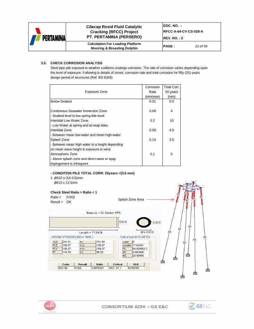
3.5. CHECK CORROSION ANALYSISSteel pipe pile exposed to weather coditions undergo corrosion. The rate of corrosion varies depending upon the level of exposure. Following is details of zones, corrosion rate and total corrosion for fifty (25) years design period of structures (Ref. BS 6349)
Corrosion Total Corr.Rate 50 years
(mm/year) (mm)Below Seabed 0.01 0.5
Contineous Seawater Immersion Zone: 0.08 4- Seabed level to low spring tide levelIntertidal Low Water Zone 0.2 10- Low Water at spring and at neap tidesIntertidal Zone 0.09 4.5- Between mean low-water and mean high-waterSplash Zone 0.14 3.5- Between mean high-water to a height depending on mean wave height & exposure to windAtmospheric Zone 0.1 5- Above splash zone and direct wave or spayimpingement is infrequent
- CONDITION PILE TOTAL CORR. 25years =(3.5 mm)1. Ø610 x (16-3.5)mm Ø610 x 12.5mm
Check Steel Ratio = Ratio < 1Ratio = 0.602Result = OK
Exposure Zone
Splash Zone Area
23 of 5023 of 5023 of 50
DOC. NO. :RFCC-A-64-CV-CS-028-A
REV. NO. : 2
PAGE :
Cilacap Resid Fluid Catalytic Cracking (RFCC) Project
PT. PERTAMINA (PERSERO)Calculation For Loading Platform
Mooring & Breasting Dolphin
Node L/C X-Trans mm Y-Trans mm
Z-Trans mm
Absolute mm
X-Rotan rad
Y-Rotan rad Z-Rotan rad
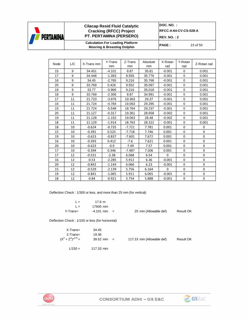
15 9 34.451 -4.101 8.87 35.81 -0.001 0 0.00117 9 34.448 -1.393 9.555 35.776 -0.001 0 0.00116 9 34.45 -2.765 9.216 35.768 -0.001 0 0.00120 9 33.769 0.426 9.552 35.097 -0.001 0 0.00119 9 33.77 -0.966 9.216 35.018 -0.001 0 0.00118 9 33.769 -2.306 8.87 34.991 -0.001 0 0.00117 11 21.723 -3.976 19.363 29.37 -0.001 0 0.00116 11 21.724 -4.784 19.063 29.295 -0.001 0 0.00115 11 21.724 -5.548 18.764 29.237 -0.001 0 0.00120 11 21.127 -0.317 19.361 28.658 -0.002 0 0.00119 11 21.128 -1.152 19.063 28.48 -0.002 0 0.00118 11 21.129 ‐1.914 18.763 28.322 ‐0.001 0 0.00118 10 ‐0.624 ‐0.735 ‐7.721 7.781 0.001 0 015 10 ‐0.391 0.525 ‐7.718 7.746 0.001 0 019 10 ‐0.623 ‐0.837 ‐7.601 7.672 0.001 0 016 10 ‐0.393 0.412 ‐7.6 7.621 0.001 0 020 10 ‐0.623 ‐0.9 ‐7.49 7.57 0.001 0 017 10 ‐0.394 0.346 ‐7.487 7.506 0.001 0 017 12 ‐0.531 ‐2.38 6.068 6.54 0 0 016 12 ‐0.53 ‐2.285 5.912 6.36 ‐0.001 0 020 12 ‐0.842 ‐1.144 6.066 6.23 ‐0.001 0 015 12 ‐0.529 ‐2.139 5.756 6.164 0 0 019 12 ‐0.841 ‐1.065 5.911 6.065 ‐0.001 0 018 12 ‐0.84 ‐0.921 5.754 5.888 ‐0.001 0 0
Deflection Check : 1/300 or less, and more than 25 mm (for vertical)
L = 17.6 mL = 17600 mm
Y-Trans= -4.101 mm < 25 mm (Allowable def) Result OK
Deflection Check : 1/150 or less (for horizontal)
34.4519.3639.52 mm < 117.33 mm (Allowable def) Result OK
L/150 = 117.33 mm
(X2 + Z2)^0.5 =
X-Trans=Z-Trans=
24 of 5024 of 5024 of 50
DOC. NO. :RFCC-A-64-CV-CS-028-A
REV. NO. : 2
PAGE :
Cilacap Resid Fluid Catalytic Cracking (RFCC) Project
PT. PERTAMINA (PERSERO)Calculation For Loading Platform
Mooring & Breasting Dolphin
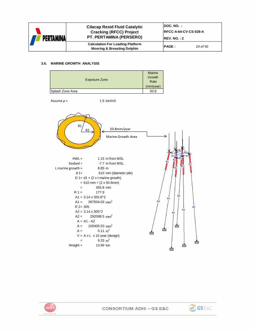
3.6. MARINE GROWTH ANALYSIS
Marine Growth
Rate(mm/year)
Splash Zone Area 50.8
Assume ρ = 1.5 ton/m3
HWL = 1.15 m from MSLSeabed = -7.7 m from MSL
L marine growth = 8.85 md 1= 610 mm (diameter pile)D 1= d1 + (2 x t marine growth)
= 610 mm + (2 x 50.8mm)= 355.8 mm
R 1 = 177.9A1 = 3.14 x 355.8^2A1 = 397504.03 mm2
R 2= 305A2 = 3.14 x 305^2A2 = 292098.5 mm2
A = A1 - A2A = 105405.53 mm2
A = 0.11 m2
V = A x L x 10 year (design)= 9.33 m3
Weight = 13.99 ton
Exposure Zone
Marine Growth Area
50.8mm/yearR2R1
25 of 5025 of 5025 of 50
DOC. NO. :RFCC-A-64-CV-CS-028-A
REV. NO. : 2
PAGE :
Cilacap Resid Fluid Catalytic Cracking (RFCC) Project
PT. PERTAMINA (PERSERO)Calculation For Loading Platform
Mooring & Breasting Dolphin
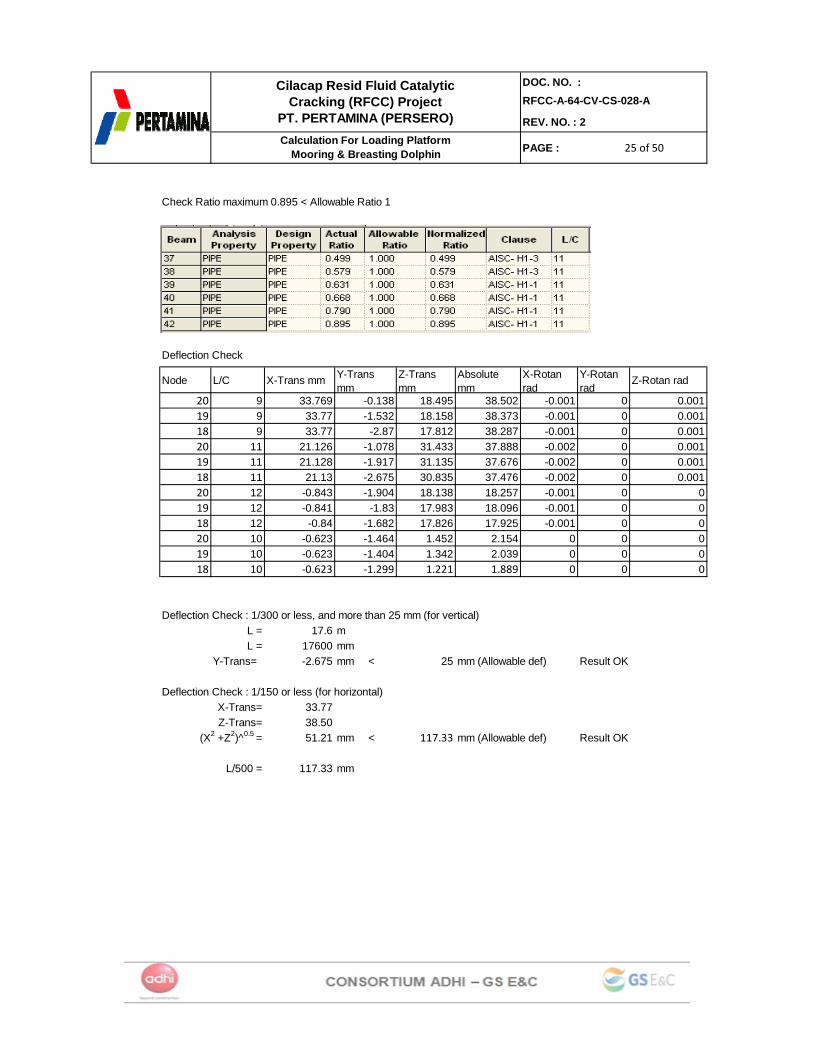
Check Ratio maximum 0.895 < Allowable Ratio 1
Deflection Check
Node L/C X-Trans mm Y-Trans mm
Z-Trans mm
Absolute mm
X-Rotan rad
Y-Rotan rad
Z-Rotan rad
20 9 33.769 -0.138 18.495 38.502 -0.001 0 0.00119 9 33.77 -1.532 18.158 38.373 -0.001 0 0.00118 9 33.77 -2.87 17.812 38.287 -0.001 0 0.00120 11 21.126 -1.078 31.433 37.888 -0.002 0 0.00119 11 21.128 -1.917 31.135 37.676 -0.002 0 0.00118 11 21.13 -2.675 30.835 37.476 -0.002 0 0.00120 12 -0.843 -1.904 18.138 18.257 -0.001 0 019 12 -0.841 -1.83 17.983 18.096 -0.001 0 018 12 -0.84 -1.682 17.826 17.925 -0.001 0 020 10 -0.623 -1.464 1.452 2.154 0 0 019 10 -0.623 -1.404 1.342 2.039 0 0 018 10 ‐0.623 ‐1.299 1.221 1.889 0 0 0
Deflection Check : 1/300 or less, and more than 25 mm (for vertical)L = 17.6 mL = 17600 mm
Y-Trans= -2.675 mm < 25 mm (Allowable def) Result OK
Deflection Check : 1/150 or less (for horizontal)33.7738.5051.21 mm < 117.33 mm (Allowable def) Result OK
L/500 = 117.33 mm
X-Trans=
(X2 +Z2)^0.5 =Z-Trans=
26 of 5026 of 5026 of 50
DOC. NO. :RFCC-A-64-CV-CS-028-A
REV. NO. : 2
PAGE :
Cilacap Resid Fluid Catalytic Cracking (RFCC) Project
PT. PERTAMINA (PERSERO)Calculation For Loading Platform
Mooring & Breasting Dolphin
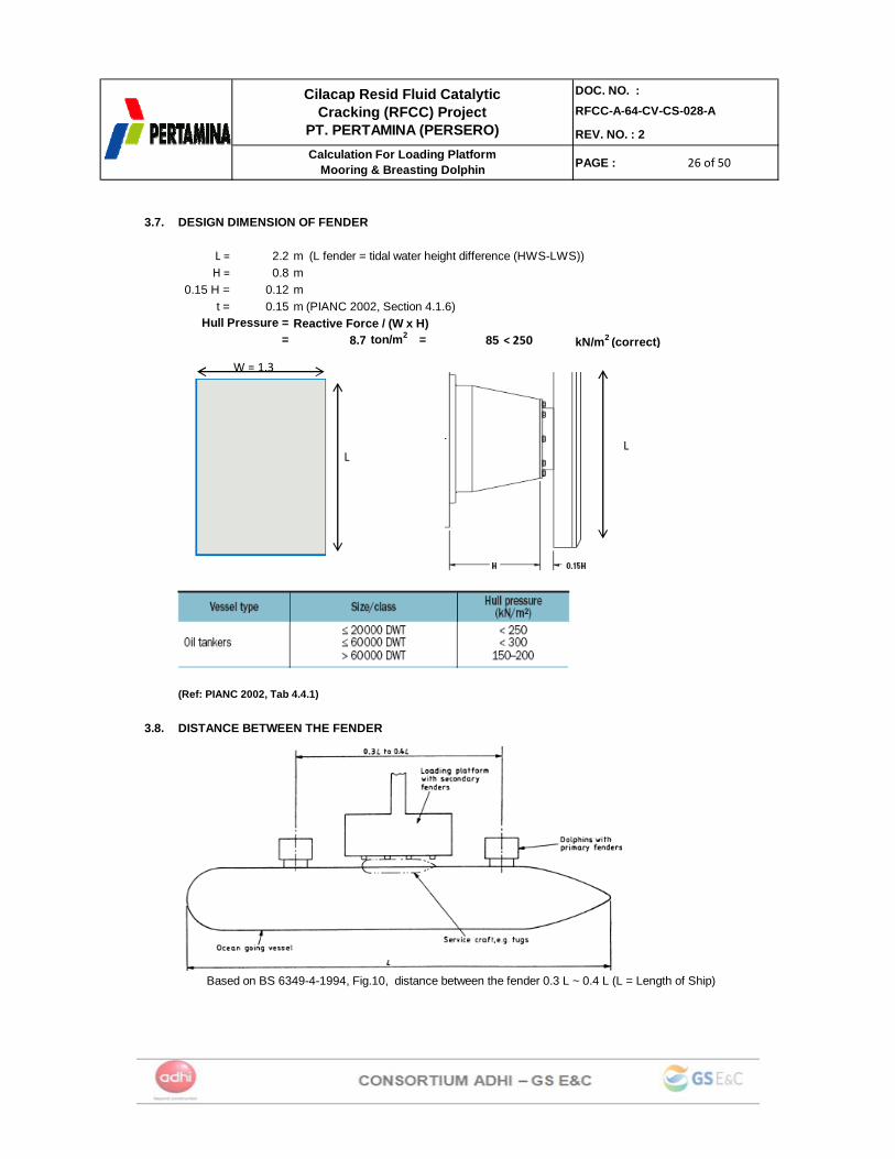
3.7. DESIGN DIMENSION OF FENDER
L = 2.2 m (L fender = tidal water height difference (HWS-LWS))H = 0.8 m
0.15 H = 0.12 mt = 0.15 m (PIANC 2002, Section 4.1.6)
Reactive Force / (W x H) 8.7 ton/m2 = 85 < 250 kN/m2 (correct)
(Ref: PIANC 2002, Tab 4.4.1)
3.8. DISTANCE BETWEEN THE FENDER
Based on BS 6349-4-1994, Fig.10, distance between the fender 0.3 L ~ 0.4 L (L = Length of Ship)
Hull Pressure =Hull Pressure =
LL
W = 1.3

27 of 5027 of 5027 of 50
DOC. NO. :RFCC-A-64-CV-CS-028-A
REV. NO. : 2
PAGE :
Cilacap Resid Fluid Catalytic Cracking (RFCC) Project
PT. PERTAMINA (PERSERO)Calculation For Loading Platform
Mooring & Breasting Dolphin
For 4500 dwt based on calculation 0.3 L ~ 0.4 L = 39.4 mbased on drawing Jetty 64 (SN-24)= 44.5 mcorrection 5.1 %
For 3000 dwtbased on calculation 0.3 L ~ 0.4 L = 34.88 mbased on drawing Jetty 64 (SN-24)= 34.5 mcorrection 0.38 %
3.9. REINFORCING CONCRETE DESIGN
S pile cap = 4 mH pile Cap = 1.5 m
fy = = 4000 kg/cm2f'c = = 280 kg/cm2
Mu = 29.551 t-m (data from STAADpro)= 2955050 kg.cm
d = 150 - 7.5 142.5 cmb= 70 cm
φ rebar = 25 mm
ρ min = 0.0018 ( ACI - 318 - 89 )
m = fy / (0.85 x f'c) = 16.81
φ = 0.9 Rn = Mu = 2.31
φ bd2
Rn = 2.31
r req'd = 1/m ( 1 - √ 1 - 2 Rn m ) fy
r req'd = 0.0006 > r min
As req'd = 5.79 cm2
Use D25 @ 200 (As prov'd) = 24.54 cm2
28 of 5028 of 5028 of 50
DOC. NO. :RFCC-A-64-CV-CS-028-A
REV. NO. : 2
PAGE :
Cilacap Resid Fluid Catalytic Cracking (RFCC) Project
PT. PERTAMINA (PERSERO)Calculation For Loading Platform
Mooring & Breasting Dolphin
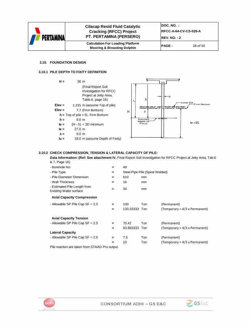
3.10. FOUNDATION DESIGN
3.10.1 PILE DEPTH TO FIXITY DEFINITION
H = 36 m
1.2357.7 (Firm Bottom)
h = Top of pile + EL. Firm Bottomh = 9.0 mIe = (H - h) = 3D minimumIe = 27.0 ms = 9.0 m
Iu = 18.0 m (assume Depth of Fixity)
3.10.2 CHECK COMPRESSION, TENSION & LATERAL CAPACITY OF PILE:
- Borehole No. = 48- Pile Type = Steel Pipe Pile (Spiral Welded)- Pile Diameter/ Dimension = 610 mm- Wall Thickness = 16 mm
= 34 mm
= 100 Ton (Permanent)= 133.33333 Ton (Temporary = 4/3 x Permanent)
= 70.42 Ton (Permanent)= 93.893333 Ton (Temporary = 4/3 x Permanent)
= 7.5 Ton (Permanent)= 10 Ton (Temporary = 4/3 x Permanent)
Pile reaction are taken from STAAD Pro output.
(Final Report Soil Investigation for RFCC Project at Jetty Area, Table.6, page 16)
Elev =
- Allowable SP Pile Cap SF = 2.5 Axial Capacity Tension
Axial Capacity Compression
Elev =m (assume Top of pile)
- Allowable SP Pile Cap SF = 2.5
- Estimated Pile Length from Existing Water surface
- Allowable SP Pile Cap SF = 2.5Lateral Capacity
Data Information: (Ref: See attachment IV, Final Report Soil Investigation for RFCC Project at Jetty Area, Tab.6 & 7, Page 16)
h
H
h
s
Ie =3S

29 of 5029 of 5029 of 50
DOC. NO. :RFCC-A-64-CV-CS-028-A
REV. NO. : 2
PAGE :
Cilacap Resid Fluid Catalytic Cracking (RFCC) Project
PT. PERTAMINA (PERSERO)Calculation For Loading Platform
Mooring & Breasting Dolphin
Node L/C Force-X Mton Force-Y Mton
Force-Z Mton
Moment-X MTon-m
Moment-Y MTon-m
Moment-Z MTon-
m23 11 -0.47 13.99 0.10 -19.91 -0.73 10.8324 11 -1.24 30.85 3.72 -20.14 -2.09 10.1325 11 -4.20 46.44 7.10 -20.02 -3.42 9.2626 11 2.07 50.93 -3.29 -18.55 1.86 10.7627 11 -1.28 70.34 -3.67 -18.94 0.43 10.4428 11 -7.02 86.55 -3.96 -19.00 -1.04 9.9424 8 0 -12.48 -4.16 -11.19 0.00 0.0023 8 -0.856 -12.22 -4.09 -11.08 0.81 0.1925 8 0.856 -12.22 -4.09 -11.08 -0.81 -0.19
Z‐Direction:
V max = V/n + ((mz * x') / (∑x2)) + ((mx * z') / (∑z2)) (x,z) = (2, 2)
X‐Direction:
V max = V/n + ((mx * z') / (∑z2)) + ((mz * x') / (∑x2)) (x,z) = (2, 2)
HorizontalH max = (Hx2 + Hz2)^0.5 / n
Vcomp Vten Hmax Vcomp Vten Hmax (ton) (ton) (ton) (ton) (ton) (ton)
11 19.91 0.00 0.48 133.33 93.89 10 0.149 OK11 54.62 0.00 3.92 133.33 93.89 10 0.410 OK11 86.60 0.00 8.25 133.33 93.89 10 0.825 OK11 71.57 0.00 3.89 133.33 93.89 10 0.537 OK11 92.94 0.00 3.89 133.33 93.89 10 0.697 OK11 110.30 0.00 8.06 133.33 93.89 10 0.827 OK8 0.00 -0.84 4.16 100 70.42 7.5 0.555 OK8 0.00 -0.78 4.18 100 70.42 7.5 0.558 OK8 0.00 -0.78 4.18 100 70.42 7.5 0.558 OK
PILE REACTIONRATIO RESULT (R<1)
PILE CAPACITYL/C

30 of 5030 of 5030 of 50
DOC. NO. :RFCC-A-64-CV-CS-028-A
REV. NO. : 2
PAGE :
Cilacap Resid Fluid Catalytic Cracking (RFCC) Project
PT. PERTAMINA (PERSERO)Calculation For Loading Platform
Mooring & Breasting Dolphin
4. MOORING DOLPHIN DOLPHIN (Type MD-1, MD-2, MD-3 & MD-4 equal dimension)
4.1. DIMENSION OF MOORING DOLPHIN (MD-1, MD-2, MD-3, & MD-4)
0.8m 0.8m2.4m
0.8m
2.4m
0.8m
1.2
31 of 5031 of 5031 of 50
DOC. NO. :RFCC-A-64-CV-CS-028-A
REV. NO. : 2
PAGE :
Cilacap Resid Fluid Catalytic Cracking (RFCC) Project
PT. PERTAMINA (PERSERO)Calculation For Loading Platform
Mooring & Breasting Dolphin
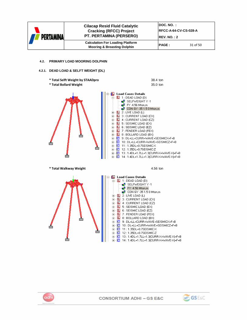
4.2. PRIMARY LOAD MOORING DOLPHIN
4.2.1. DEAD LOAD & SELFT WEIGHT (DL)
38.4 ton35.0 ton
4.56 ton
* Total Selft Weight by STAADpro* Total Bollard Weight
* Total Walkway Weight
32 of 5032 of 5032 of 50
DOC. NO. :RFCC-A-64-CV-CS-028-A
REV. NO. : 2
PAGE :
Cilacap Resid Fluid Catalytic Cracking (RFCC) Project
PT. PERTAMINA (PERSERO)Calculation For Loading Platform
Mooring & Breasting Dolphin
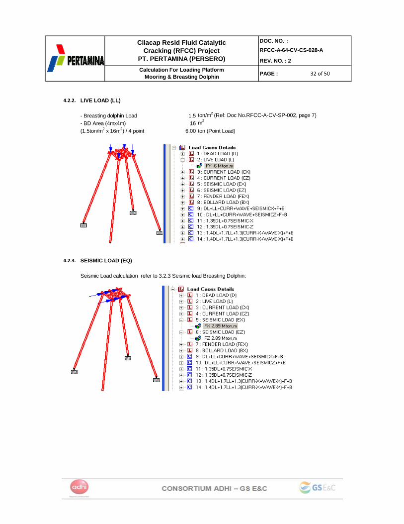
4.2.2. LIVE LOAD (LL)
- Breasting dolphin Load 1.5 ton/m2 (Ref: Doc No.RFCC-A-CV-SP-002, page 7)- BD Area (4mx4m) 16 m2
6.00 ton (Point Load)
4.2.3. SEISMIC LOAD (EQ)
Seismic Load calculation refer to 3.2.3 Seismic load Breasting Dolphin:
(1.5ton/m2 x 16m2) / 4 point
33 of 5033 of 5033 of 50
DOC. NO. :RFCC-A-64-CV-CS-028-A
REV. NO. : 2
PAGE :
Cilacap Resid Fluid Catalytic Cracking (RFCC) Project
PT. PERTAMINA (PERSERO)Calculation For Loading Platform
Mooring & Breasting Dolphin
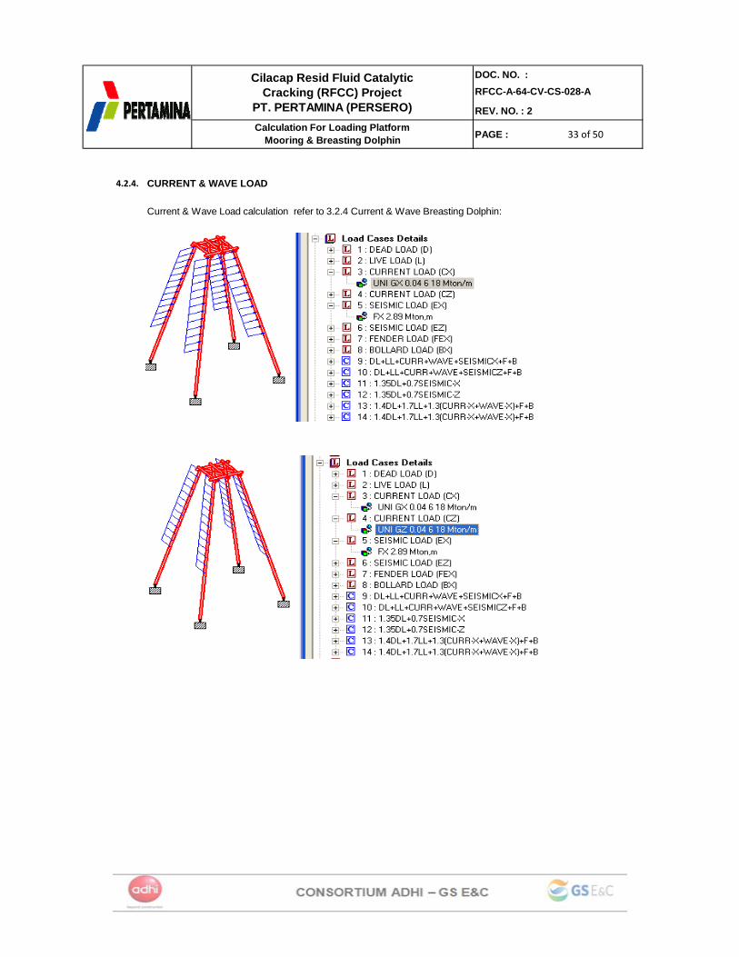
4.2.4. CURRENT & WAVE LOAD
Current & Wave Load calculation refer to 3.2.4 Current & Wave Breasting Dolphin:
34 of 5034 of 5034 of 50
DOC. NO. :RFCC-A-64-CV-CS-028-A
REV. NO. : 2
PAGE :
Cilacap Resid Fluid Catalytic Cracking (RFCC) Project
PT. PERTAMINA (PERSERO)Calculation For Loading Platform
Mooring & Breasting Dolphin
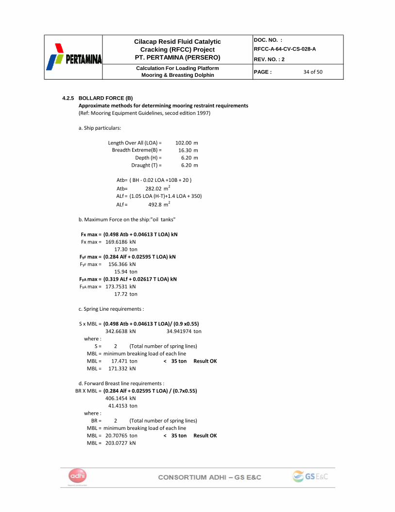
4.2.5 BOLLARD FORCE (B)Approximate methods for determining mooring restraint requirements(Ref: Mooring Equipment Guidelines, secod edition 1997)
a. Ship particulars:
102.00 m16.30 m6.20 m6.20 m
Atb= ( BH ‐ 0.02 LOA +10B + 20 )
Atb= 282.02 m2
ALf = (1.05 LOA (H‐T)+1.4 LOA + 350)
ALf = 492.8 m2
b. Maximum Force on the ship:"oil tanks"
Fx max = (0.498 Atb + 0.04613 T LOA) kNFx max = 169.6186 kN
17.30 tonFyF max = (0.284 Alf + 0.02595 T LOA) kNFyF max = 156.366 kN
15.94 tonFyA max = (0.319 ALf + 0.02617 T LOA) kNFyA max = 173.7531 kN
17.72 ton
c. Spring Line requirements :
S x MBL = (0.498 Atb + 0.04613 T LOA)/ (0.9 x0.55)342.6638 kN 34.941974 ton
where :S = 2 (Total number of spring lines)
MBL = minimum breaking load of each lineMBL = 17.471 ton < 35 ton Result OKMBL = 171.332 kN
d. Forward Breast line requirements :BR X MBL = (0.284 Alf + 0.02595 T LOA) / (0.7x0.55)
406.1454 kN41.4153 ton
where :BR = 2 (Total number of spring lines)
MBL = minimum breaking load of each lineMBL = 20.70765 ton < 35 ton Result OKMBL = 203.0727 kN
Length Over All (LOA) =Breadth Extreme(B) =
Draught (T) =Depth (H) =
35 of 5035 of 5035 of 50
DOC. NO. :RFCC-A-64-CV-CS-028-A
REV. NO. : 2
PAGE :
Cilacap Resid Fluid Catalytic Cracking (RFCC) Project
PT. PERTAMINA (PERSERO)Calculation For Loading Platform
Mooring & Breasting Dolphin
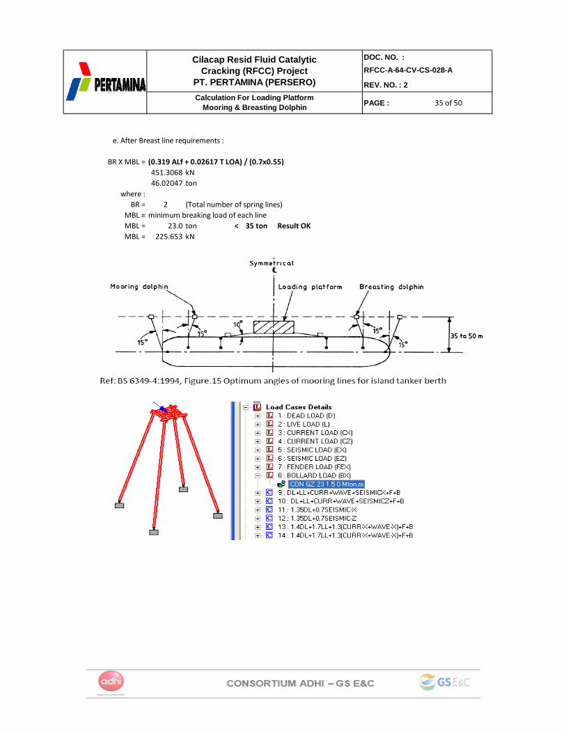
e. After Breast line requirements :
BR X MBL = (0.319 ALf + 0.02617 T LOA) / (0.7x0.55)451.3068 kN46.02047 ton
where :BR = 2 (Total number of spring lines)
MBL = minimum breaking load of each lineMBL = 23.0 ton < 35 ton Result OKMBL = 225.653 kN
36 of 5036 of 5036 of 50
DOC. NO. :RFCC-A-64-CV-CS-028-A
REV. NO. : 2
PAGE :
Cilacap Resid Fluid Catalytic Cracking (RFCC) Project
PT. PERTAMINA (PERSERO)Calculation For Loading Platform
Mooring & Breasting Dolphin
4.3. LOAD COMBINATIONAnalysis Load Combination Mooring Dolphin = Breasting Dolphin
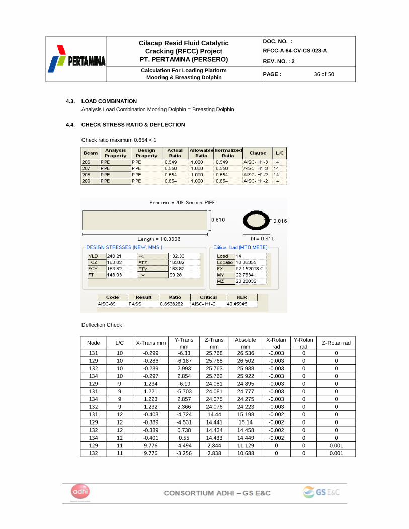
4.4. CHECK STRESS RATIO & DEFLECTION
Check ratio maximum 0.654 < 1
Deflection Check
Node L/C X-Trans mm Y-Trans mm
Z-Trans mm
Absolute mm
X-Rotan rad
Y-Rotan rad
Z-Rotan rad
131 10 -0.299 -6.33 25.768 26.536 -0.003 0 0129 10 -0.286 -6.187 25.768 26.502 -0.003 0 0132 10 -0.289 2.993 25.763 25.938 -0.003 0 0134 10 -0.297 2.854 25.762 25.922 -0.003 0 0129 9 1.234 -6.19 24.081 24.895 -0.003 0 0131 9 1.221 -5.703 24.081 24.777 -0.003 0 0134 9 1.223 2.857 24.075 24.275 -0.003 0 0132 9 1.232 2.366 24.076 24.223 -0.003 0 0131 12 -0.403 -4.724 14.44 15.198 -0.002 0 0129 12 -0.389 -4.531 14.441 15.14 -0.002 0 0132 12 -0.389 0.738 14.434 14.458 -0.002 0 0134 12 ‐0.401 0.55 14.433 14.449 ‐0.002 0 0129 11 9.776 ‐4.494 2.844 11.129 0 0 0.001132 11 9.776 ‐3.256 2.838 10.688 0 0 0.001

37 of 5037 of 5037 of 50
DOC. NO. :RFCC-A-64-CV-CS-028-A
REV. NO. : 2
PAGE :
Cilacap Resid Fluid Catalytic Cracking (RFCC) Project
PT. PERTAMINA (PERSERO)Calculation For Loading Platform
Mooring & Breasting Dolphin
Deflection Check : 1/300 or less, and more than 25 mm (for vertical)L = 17.6 mL = 17600 mm
Y-Trans= -6.33 mm < 25 mm (Allowable def) Result OK
Deflection Check : 1/150 or less (for horizontal)9.78
25.7727.56 mm < 117.33 mm (Allowable def) Result OK
L/500 = 117.33 mm
4.5. CHECK CORROSION ANALYSISAnalysis Check corrosion Mooring Dolphin = Breasting Dolphin
Steel pipe pile exposed to weather coditions undergo corrosion. The rate of corrosion varies depending upon the level of exposure. Following is details of zones, corrosion rate and total corrosion for fifty (25) years design period of structures (Ref. BS 6349)
Corrosion Total Corr.Rate 50 years
(mm/year) (mm)Below Seabed 0.01 0.5
Contineous Seawater Immersion Zone: 0.08 4- Seabed level to low spring tide levelIntertidal Low Water Zone 0.2 10- Low Water at spring and at neap tidesIntertidal Zone 0.09 4.5- Between mean low-water and mean high-waterSplash Zone 0.14 3.5- Between mean high-water to a height depending on mean wave height & exposure to windAtmospheric Zone 0.1 5- Above splash zone and direct wave or spayimpingement is infrequent
Exposure Zone
X-Trans=Z-Trans=
(X2 +Z2)^0.5 =
38 of 5038 of 5038 of 50
DOC. NO. :RFCC-A-64-CV-CS-028-A
REV. NO. : 2
PAGE :
Cilacap Resid Fluid Catalytic Cracking (RFCC) Project
PT. PERTAMINA (PERSERO)Calculation For Loading Platform
Mooring & Breasting Dolphin
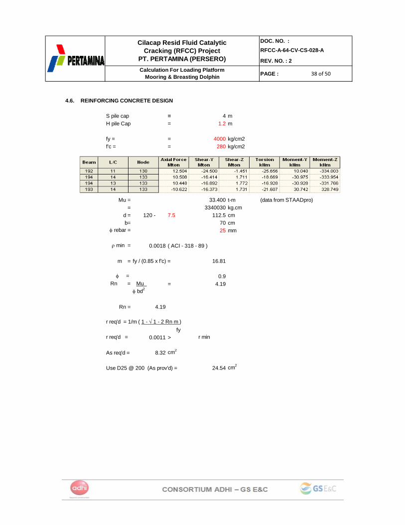
4.6. REINFORCING CONCRETE DESIGN
S pile cap = 4 mH pile Cap = 1.2 m
fy = = 4000 kg/cm2f'c = = 280 kg/cm2
Mu = 33.400 t-m (data from STAADpro)= 3340030 kg.cm
d = 120 - 7.5 112.5 cmb= 70 cm
φ rebar = 25 mm
ρ min = 0.0018 ( ACI - 318 - 89 )
m = fy / (0.85 x f'c) = 16.81
φ = 0.9 Rn = Mu = 4.19
φ bd2
Rn = 4.19
r req'd = 1/m ( 1 - √ 1 - 2 Rn m ) fy
r req'd = 0.0011 > r min
As req'd = 8.32 cm2
Use D25 @ 200 (As prov'd) = 24.54 cm2
39 of 5039 of 5039 of 50
DOC. NO. :RFCC-A-64-CV-CS-028-A
REV. NO. : 2
PAGE :
Cilacap Resid Fluid Catalytic Cracking (RFCC) Project
PT. PERTAMINA (PERSERO)Calculation For Loading Platform
Mooring & Breasting Dolphin
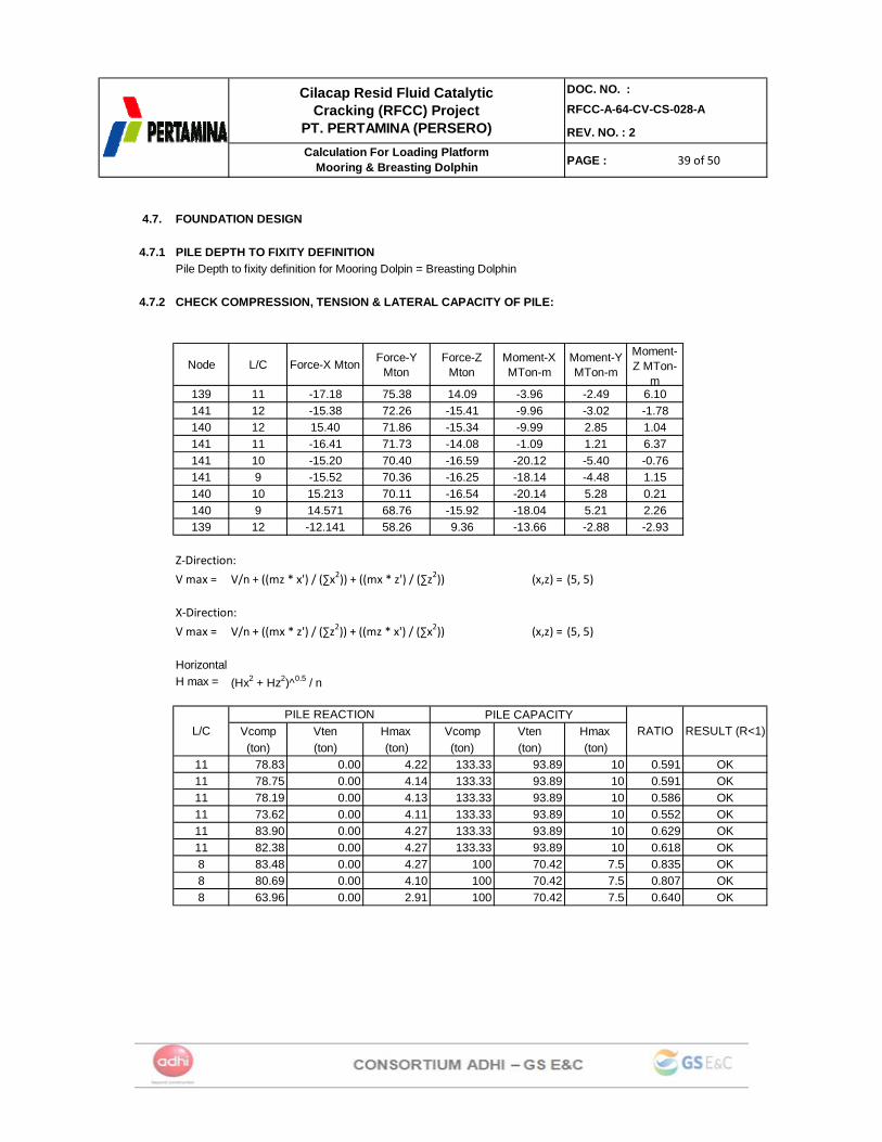
4.7. FOUNDATION DESIGN
4.7.1 PILE DEPTH TO FIXITY DEFINITIONPile Depth to fixity definition for Mooring Dolpin = Breasting Dolphin
4.7.2 CHECK COMPRESSION, TENSION & LATERAL CAPACITY OF PILE:
Node L/C Force-X Mton Force-Y Mton
Force-Z Mton
Moment-X MTon-m
Moment-Y MTon-m
Moment-Z MTon-
m139 11 -17.18 75.38 14.09 -3.96 -2.49 6.10141 12 -15.38 72.26 -15.41 -9.96 -3.02 -1.78140 12 15.40 71.86 -15.34 -9.99 2.85 1.04141 11 -16.41 71.73 -14.08 -1.09 1.21 6.37141 10 -15.20 70.40 -16.59 -20.12 -5.40 -0.76141 9 -15.52 70.36 -16.25 -18.14 -4.48 1.15140 10 15.213 70.11 -16.54 -20.14 5.28 0.21140 9 14.571 68.76 -15.92 -18.04 5.21 2.26139 12 -12.141 58.26 9.36 -13.66 -2.88 -2.93
Z‐Direction:
V max = V/n + ((mz * x') / (∑x2)) + ((mx * z') / (∑z2)) (x,z) = (5, 5)
X‐Direction:
V max = V/n + ((mx * z') / (∑z2)) + ((mz * x') / (∑x2)) (x,z) = (5, 5)
HorizontalH max = (Hx2 + Hz2)^0.5 / n
Vcomp Vten Hmax Vcomp Vten Hmax (ton) (ton) (ton) (ton) (ton) (ton)
11 78.83 0.00 4.22 133.33 93.89 10 0.591 OK11 78.75 0.00 4.14 133.33 93.89 10 0.591 OK11 78.19 0.00 4.13 133.33 93.89 10 0.586 OK11 73.62 0.00 4.11 133.33 93.89 10 0.552 OK11 83.90 0.00 4.27 133.33 93.89 10 0.629 OK11 82.38 0.00 4.27 133.33 93.89 10 0.618 OK8 83.48 0.00 4.27 100 70.42 7.5 0.835 OK8 80.69 0.00 4.10 100 70.42 7.5 0.807 OK8 63.96 0.00 2.91 100 70.42 7.5 0.640 OK
L/CPILE REACTION PILE CAPACITY
RATIO RESULT (R<1)
40 of 5040 of 5040 of 50
DOC. NO. :RFCC-A-64-CV-CS-028-A
REV. NO. : 2
PAGE :
Cilacap Resid Fluid Catalytic Cracking (RFCC) Project
PT. PERTAMINA (PERSERO)Calculation For Loading Platform
Mooring & Breasting Dolphin
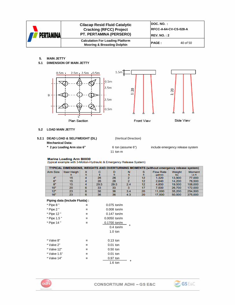
5. MAIN JETTY5.1 DIMENSION OF MAIN JETTY
5.2 LOAD MAIN JETTY
5.2.1 DEAD LOAD & SELFWEIGHT (DL) (Vertical Direction)Mechanical Data:
6 ton (assume 6") include emergency release system11 ton m
Piping data (Include Fluida) :* Pipe 8 " = 0.075 ton/m* Pipe 2 " = 0.008 ton/m* Pipe 12 " = 0.147 ton/m* Pipe 1.5 " = 0.0050 ton/m* Pipe 14 " = 0.1700 ton/m
0.4 ton/m1.0 ton
* Valve 8" = 0.13 ton* Valve 2" = 0.01 ton* Valve 12" = 0.50 ton* Valve 1.5" = 0.01 ton* Valve 14" = 0.97 ton
1.6 ton
* 2 pcs Loading Arm size 6"
+
+
41 of 5041 of 5041 of 50
DOC. NO. :RFCC-A-64-CV-CS-028-A
REV. NO. : 2
PAGE :
Cilacap Resid Fluid Catalytic Cracking (RFCC) Project
PT. PERTAMINA (PERSERO)Calculation For Loading Platform
Mooring & Breasting Dolphin
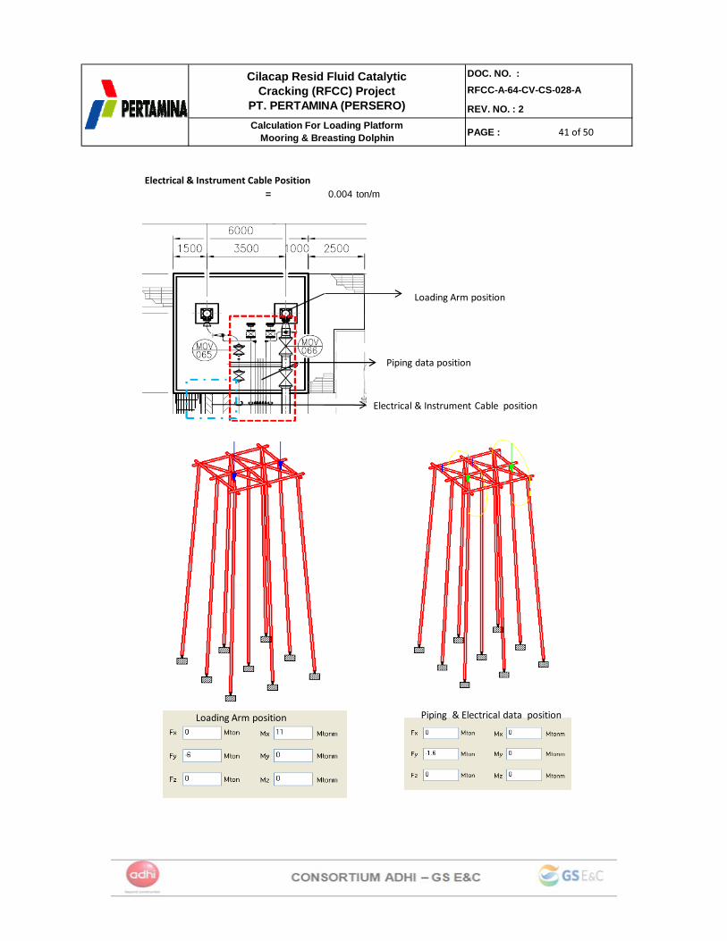
Electrical & Instrument Cable Position= 0.004 ton/m
Piping data position
Loading Arm position
Electrical & Instrument Cable position
Loading Arm position Piping & Electrical data position
42 of 5042 of 5042 of 50
DOC. NO. :RFCC-A-64-CV-CS-028-A
REV. NO. : 2
PAGE :
Cilacap Resid Fluid Catalytic Cracking (RFCC) Project
PT. PERTAMINA (PERSERO)Calculation For Loading Platform
Mooring & Breasting Dolphin
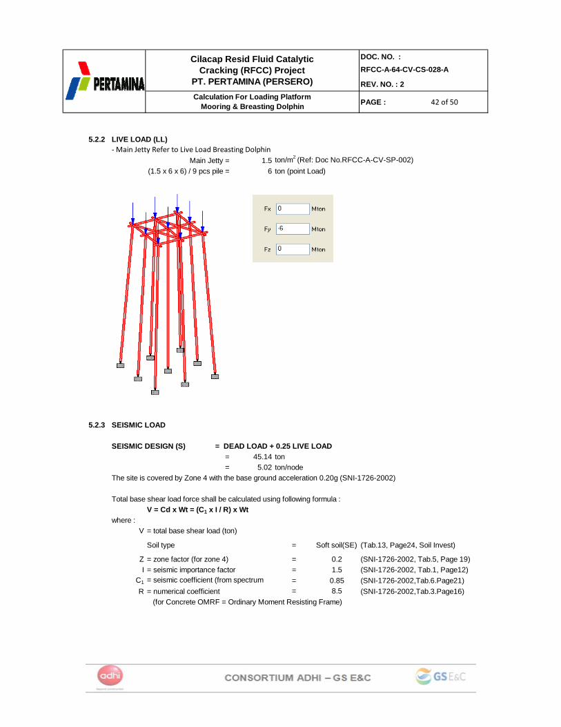
5.2.2 LIVE LOAD (LL)
Main Jetty = 1.5 ton/m2 (Ref: Doc No.RFCC-A-CV-SP-002)(1.5 x 6 x 6) / 9 pcs pile = 6 ton (point Load)
5.2.3 SEISMIC LOAD
SEISMIC DESIGN (S) = DEAD LOAD + 0.25 LIVE LOAD= 45.14 ton= 5.02 ton/node
The site is covered by Zone 4 with the base ground acceleration 0.20g (SNI-1726-2002)
Total base shear load force shall be calculated using following formula :V = Cd x Wt = (C1 x I / R) x Wt
where :V = total base shear load (ton)
Soil type = Soft soil(SE) (Tab.13, Page24, Soil Invest)
Z = zone factor (for zone 4) = 0.2 (SNI-1726-2002, Tab.5, Page 19)I = seismic importance factor = 1.5 (SNI-1726-2002, Tab.1, Page12)
C1 = 0.85 (SNI-1726-2002,Tab.6.Page21)R = numerical coefficient = 8.5 (SNI-1726-2002,Tab.3.Page16)
(for Concrete OMRF = Ordinary Moment Resisting Frame)
‐ Main Jetty Refer to Live Load Breasting Dolphin
= seismic coefficient (from spectrum
43 of 5043 of 5043 of 50
DOC. NO. :RFCC-A-64-CV-CS-028-A
REV. NO. : 2
PAGE :
Cilacap Resid Fluid Catalytic Cracking (RFCC) Project
PT. PERTAMINA (PERSERO)Calculation For Loading Platform
Mooring & Breasting Dolphin
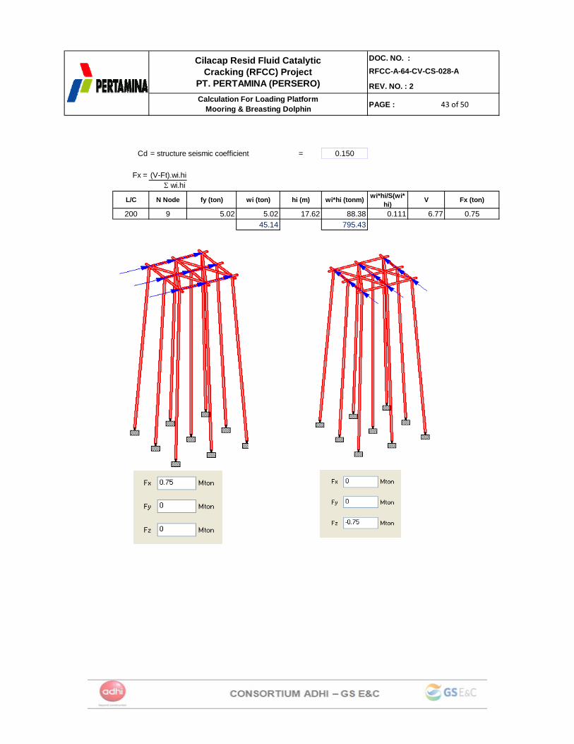
Cd = structure seismic coefficient = 0.150
Fx = (V-Ft).wi.hiΣ wi.hi
L/C N Node fy (ton) wi (ton) hi (m) wi*hi (tonm) wi*hi/S(wi*hi)
V Fx (ton)
200 9 5.02 5.02 17.62 88.38 0.111 6.77 0.7545.14 795.43
44 of 5044 of 5044 of 50
DOC. NO. :RFCC-A-64-CV-CS-028-A
REV. NO. : 2
PAGE :
Cilacap Resid Fluid Catalytic Cracking (RFCC) Project
PT. PERTAMINA (PERSERO)Calculation For Loading Platform
Mooring & Breasting Dolphin
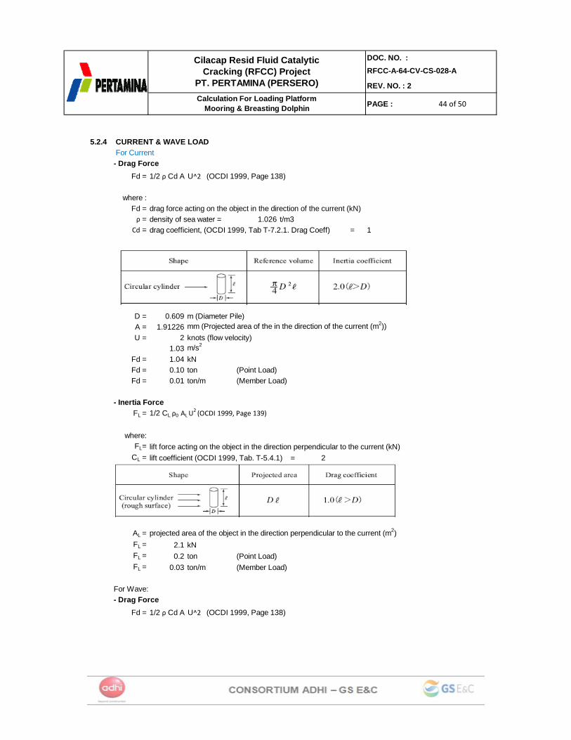
5.2.4 CURRENT & WAVE LOAD For Current- Drag Force
Fd =
where :Fd = drag force acting on the object in the direction of the current (kN)ρ = density of sea water = 1.026 t/m3
Cd = drag coefficient, (OCDI 1999, Tab T-7.2.1. Drag Coeff) = 1
D = 0.609 m (Diameter Pile)A = 1.91226 mm (Projected area of the in the direction of the current (m2))U = 2 knots (flow velocity)
1.03 m/s2
Fd = 1.04 kNFd = 0.10 ton (Point Load)Fd = 0.01 ton/m (Member Load)
- Inertia ForceFL = 1/2 CL ρ0 AL U
2 (OCDI 1999, Page 139)
where:FL= lift force acting on the object in the direction perpendicular to the current (kN)
CL = lift coefficient (OCDI 1999, Tab. T-5.4.1) = 2
AL = projected area of the object in the direction perpendicular to the current (m2)FL = 2.1 kNFL = 0.2 ton (Point Load)FL = 0.03 ton/m (Member Load)
For Wave:- Drag Force
Fd =
1/2 ρ Cd A U^2 (OCDI 1999, Page 138)
1/2 ρ Cd A U^2 (OCDI 1999, Page 138)

45 of 5045 of 5045 of 50
DOC. NO. :RFCC-A-64-CV-CS-028-A
REV. NO. : 2
PAGE :
Cilacap Resid Fluid Catalytic Cracking (RFCC) Project
PT. PERTAMINA (PERSERO)Calculation For Loading Platform
Mooring & Breasting Dolphin
where :Fd = drag force acting on the object in the direction of the current (kN)ρ = density of sea water = 1.026 t/m3
Cd = drag coefficient, (OCDI 1999, Tab T-7.2.1. Drag Coeff) = 1
D = 0.609 m (Diameter Pile)A = 1.91226 mm (Projected area of the in the direction of the current (m2))U = 2 knots (wave velocity)
1.03 m/s2
Fd = 1.04 kNFd = 0.10 ton
- Inertia ForceFL = 1/2 CL ρ0 AL U
2 (OCDI 1999, Page 139)
where:FL= lift force acting on the object in the direction perpendicular to the current (kN)
CL = lift coefficient (OCDI 1999, Tab. T-5.4.1) = 2
AL = projected area of the object in the direction perpendicular to the current (m2)FL = 2.1 kNFL = 0.2 ton
46 of 5046 of 5046 of 50
DOC. NO. :RFCC-A-64-CV-CS-028-A
REV. NO. : 2
PAGE :
Cilacap Resid Fluid Catalytic Cracking (RFCC) Project
PT. PERTAMINA (PERSERO)Calculation For Loading Platform
Mooring & Breasting Dolphin
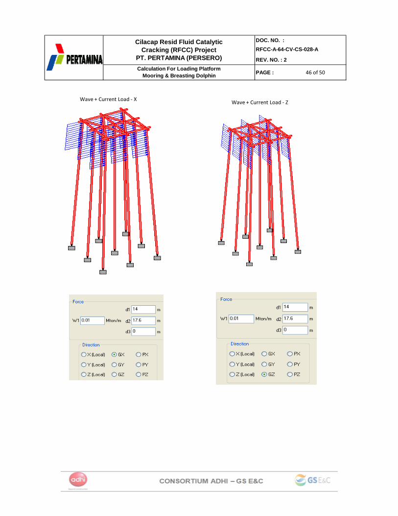
Wave + Current Load ‐ X Wave + Current Load ‐ Z
47 of 5047 of 5047 of 50
DOC. NO. :RFCC-A-64-CV-CS-028-A
REV. NO. : 2
PAGE :
Cilacap Resid Fluid Catalytic Cracking (RFCC) Project
PT. PERTAMINA (PERSERO)Calculation For Loading Platform
Mooring & Breasting Dolphin
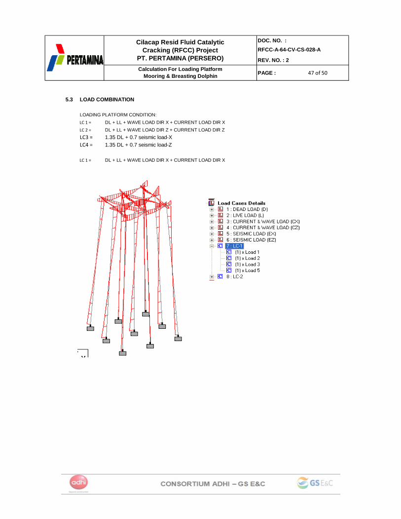
5.3 LOAD COMBINATION
LOADING PLATFORM CONDITION:LC 1 = DL + LL + WAVE LOAD DIR X + CURRENT LOAD DIR X LC 2 = DL + LL + WAVE LOAD DIR Z + CURRENT LOAD DIR Z LC3 = 1.35 DL + 0.7 seismic load-XLC4 = 1.35 DL + 0.7 seismic load-Z
LC 1 = DL + LL + WAVE LOAD DIR X + CURRENT LOAD DIR X
48 of 5048 of 5048 of 50
DOC. NO. :RFCC-A-64-CV-CS-028-A
REV. NO. : 2
PAGE :
Cilacap Resid Fluid Catalytic Cracking (RFCC) Project
PT. PERTAMINA (PERSERO)Calculation For Loading Platform
Mooring & Breasting Dolphin
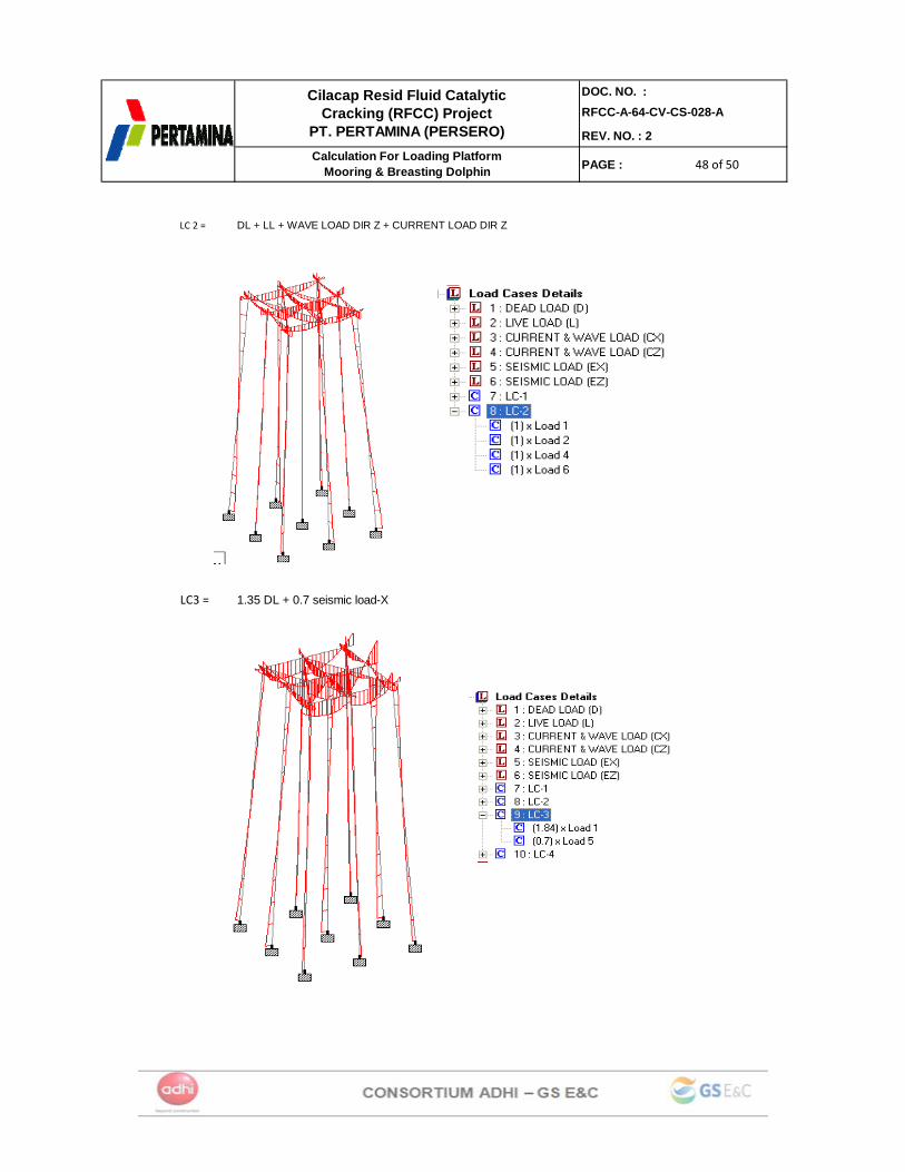
LC 2 = DL + LL + WAVE LOAD DIR Z + CURRENT LOAD DIR Z
LC3 = 1.35 DL + 0.7 seismic load-X
49 of 5049 of 5049 of 50
DOC. NO. :RFCC-A-64-CV-CS-028-A
REV. NO. : 2
PAGE :
Cilacap Resid Fluid Catalytic Cracking (RFCC) Project
PT. PERTAMINA (PERSERO)Calculation For Loading Platform
Mooring & Breasting Dolphin
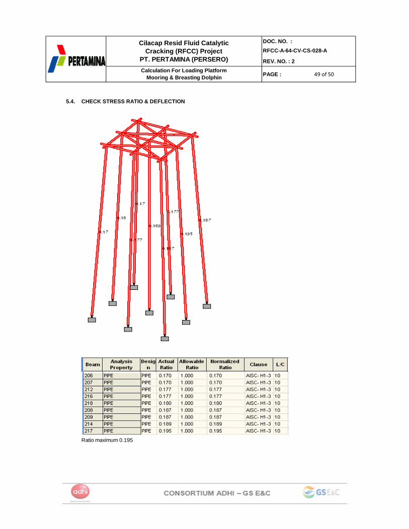
5.4. CHECK STRESS RATIO & DEFLECTION
Ratio maximum 0.195
50 of 5050 of 5050 of 50
DOC. NO. :RFCC-A-64-CV-CS-028-A
REV. NO. : 2
PAGE :
Cilacap Resid Fluid Catalytic Cracking (RFCC) Project
PT. PERTAMINA (PERSERO)Calculation For Loading Platform
Mooring & Breasting Dolphin
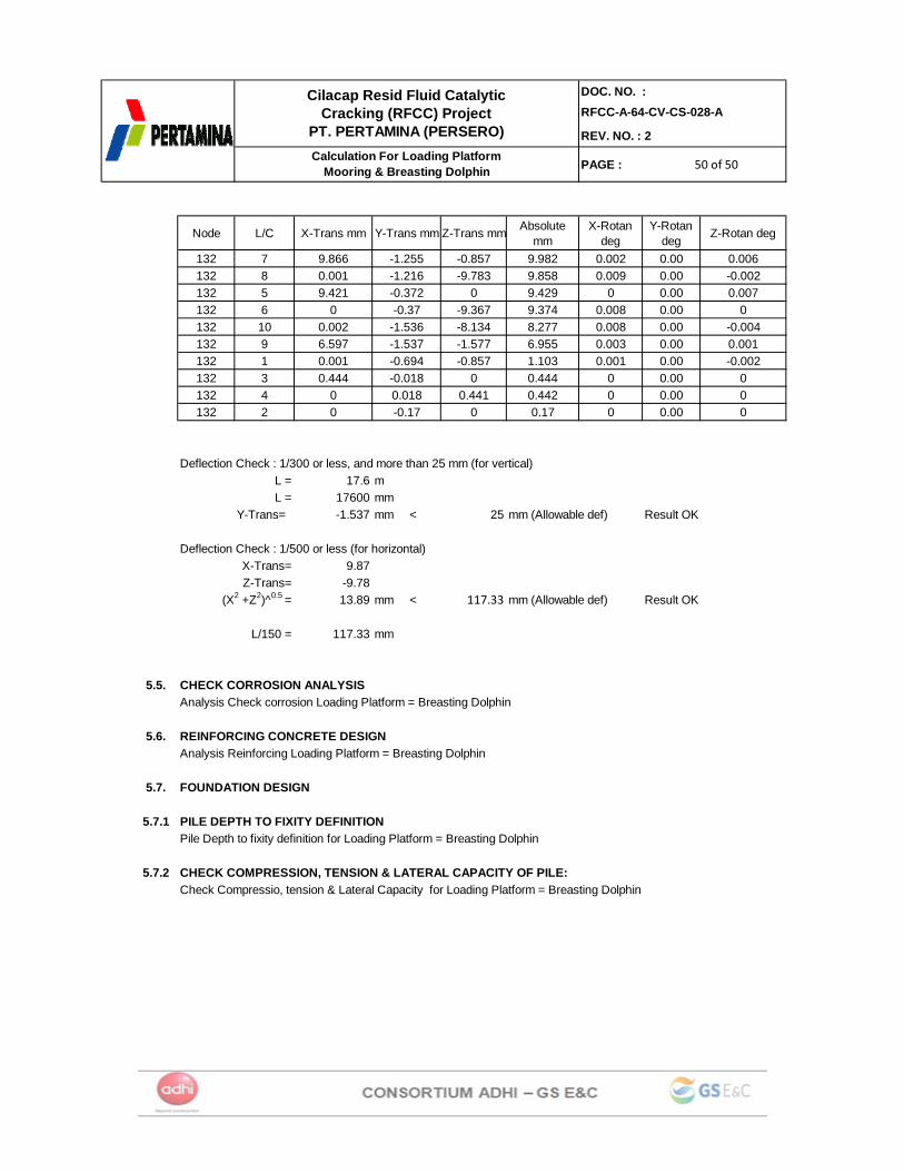
Node L/C X-Trans mm Y-Trans mm Z-Trans mm Absolute mm
X-Rotan deg
Y-Rotan deg Z-Rotan deg
132 7 9.866 -1.255 -0.857 9.982 0.002 0.00 0.006132 8 0.001 -1.216 -9.783 9.858 0.009 0.00 -0.002132 5 9.421 -0.372 0 9.429 0 0.00 0.007132 6 0 -0.37 -9.367 9.374 0.008 0.00 0132 10 0.002 -1.536 -8.134 8.277 0.008 0.00 -0.004132 9 6.597 -1.537 -1.577 6.955 0.003 0.00 0.001132 1 0.001 -0.694 -0.857 1.103 0.001 0.00 -0.002132 3 0.444 -0.018 0 0.444 0 0.00 0132 4 0 0.018 0.441 0.442 0 0.00 0132 2 0 -0.17 0 0.17 0 0.00 0
Deflection Check : 1/300 or less, and more than 25 mm (for vertical)L = 17.6 mL = 17600 mm
Y-Trans= -1.537 mm < 25 mm (Allowable def) Result OK
Deflection Check : 1/500 or less (for horizontal)9.87
-9.7813.89 mm < 117.33 mm (Allowable def) Result OK
L/150 = 117.33 mm
5.5. CHECK CORROSION ANALYSISAnalysis Check corrosion Loading Platform = Breasting Dolphin
5.6. REINFORCING CONCRETE DESIGN Analysis Reinforcing Loading Platform = Breasting Dolphin
5.7. FOUNDATION DESIGN
5.7.1 PILE DEPTH TO FIXITY DEFINITIONPile Depth to fixity definition for Loading Platform = Breasting Dolphin
5.7.2 CHECK COMPRESSION, TENSION & LATERAL CAPACITY OF PILE:Check Compressio, tension & Lateral Capacity for Loading Platform = Breasting Dolphin
Z-Trans=X-Trans=
(X2 +Z2)^0.5 =