Embed Size (px)
Citation preview

Report on Proposals – June 2012 NFPA 55_______________________________________________________________________________________________55- Log #CP1
_______________________________________________________________________________________________Technical Committee on Industrial and Medical Gases,
Revise text to read as follows:Minimum distance requirements for the S.I. unit table are miscalculated. 15 ft is translated as 5.04, 5.6, 3.64, 4.31,
4.13, or 4.7 meters. Please revise appropriately.See above.
_______________________________________________________________________________________________55- Log #CP2
_______________________________________________________________________________________________Technical Committee on Industrial and Medical Gases,
Review entire document to: 1) Update any extracted material by preparing separate proposals todo so, and 2) review and update references to other organizations documents, by preparing proposal(s) as required.
To conform to the NFPA Regulations Governing Committee Projects.
_______________________________________________________________________________________________55- Log #128
_______________________________________________________________________________________________Larry L. Fluer, Fluer, Inc. / Rep. Compressed Gas Association
The first edition of NFPA 2 is on the consent calendar for adoption as NFPA’s new hydrogentechnology code due to be published in the fall of 2011. NFPA 55 has been used as the source document forfundamental requirements for hydrogen as they will appear in NFPA 2. In some cases extract text has been revised bythe NFPA 2 Technical Committee either because further clarification was needed, or in cases where a potential conflictwas apparent. NFPA 2 will contain a new annex on explosion control where the hazards of explosion are of concernincluding the phenomenon of deflagration to detonation transition.A review of the NFPA 2 ROC draft should be conducted by the IMG TC where NFPA 55 extract material has been
used, and where differences are found the changes must be evaluated to determine whether an additional change iswarranted in NFPA 55, or whether the changes made by the NFPA 2 TC are appropriate.
To be developed.
_______________________________________________________________________________________________55- Log #135
_______________________________________________________________________________________________Larry L. Fluer, Fluer, Inc. / Rep. Compressed Gas Association
The term “cylinders, containers and tanks” is the terminology that needs to be used in a consistentfashion throughout the document when the term is intended to refer to the types of packages intended. In some casesthe term that is used is “containers, cylinders and tanks” and at other times it may be cylinders, containers and tanks.One method needs to be used for consistency. The preferred order has been “cylinders, containers and tanks.” Seethe following sections for examples of “containers, cylinders and tanks”: 6.16.4; 7.1; 7.1.4.1.5; 7.1.4.2.1; 7.1.4.2.1.1;7.1.4.2.2. For examples of “cylinders containers and tanks” see the following sections: 3.3.22.1; 4.4; 6.13.1; 6.15.2;6.17.1.2; 7.1.4.1.7.3(A).
Editorial, but the use of the term should be consistent to add to the credibility of the document.
1Printed on 1/6/2011

Report on Proposals – June 2012 NFPA 55_______________________________________________________________________________________________55- Log #54
_______________________________________________________________________________________________Larry L. Fluer, Fluer, Inc. / Rep. Compressed Gas Association
Revise text to read as follows:American Society of Mechanical Engineers, Three Park Avenue, New York, NY
10016-5990.ASME A13.1, 1996 2007.ASME B31.3, 2008 edition.ASME B31.12, , 2008 editionASME “Pressure Vessels,” Section VIII, 2010.
Changed date of ASME A13.1 to latest revision.Added reference to ASME B31.12 (reference to B31.3 changed to B31.12 in material-specific Chapters of NFPA 55).
Although ASME B31.12 is an “American National Standard” by declaration, the title is ASME B31.3. Similar changesmay have occurred with other ASME documents.
_______________________________________________________________________________________________55- Log #61
_______________________________________________________________________________________________Larry L. Fluer, Fluer, Inc. / Rep. Compressed Gas Association
Add new text to read as follows:A facility approved by DOT or TC to perform cylinder requalification,
inspection, testing, certification or repair required by transportation regulations.Persons or facilities that meet the requirements of DOT or TC to inspect, test, certify, repair, or rebuild
a cylinder in accordance with a DOT specification or a UN pressure receptacle under the regulations issued by theseagencies must be approved under specified criteria in order to receive the issuance of a requalifier identification number(RIN). The RIN acts as the evidence of approval to requalify DOT/TC specification or special permit cylinders, or UNpressure receptacles if it is determined, based on the applicant’s submission and other available information, that theapplicant’s qualifications and/or facility are adequate to perform the requested functions in accordance with theregulations.Cylinder requalifiers are in effect an extension of the supply and distribution chain where containers are received,
segregated, examined, serviced and processed. These containers may contain compressed gases when received, andthe practices exercised by the suppliers including nesting, transport, security, etc. apply as the cylinders move throughthe process.Section 7.1.5.4 and others provide direction to the handling of cylinders, containers and tanks that are being serviced.
This definition works in concert with correlating changes to expand the requirements and exemptions granted to the gasmanufacturers or distributors to include the category of requalifiers as those involved with cylinder servicing (other thanthe gas suppliers).For additional information see 49 CFR 107.805.
2Printed on 1/6/2011

Report on Proposals – June 2012 NFPA 55_______________________________________________________________________________________________55- Log #62
_______________________________________________________________________________________________Larry L. Fluer, Fluer, Inc. / Rep. Compressed Gas Association
Revise text to read as follows:A mechanical device used for increasing the pressure and the resultant density of a gas through
the act of compression.The term compressor is used without a definition as it relates to NFPA 55. Compressor has been
defined in NFPA 853 with the definition extracted into NFPA 2. As defined there the term is limited to “A device used forincreasing the pressure and density of a gas.” Including a definition in NFPA 55 is appropriate to be used as the sourcedocument for requirements for all compressed gases including the definitions to be extracted into NFPA 2.
_______________________________________________________________________________________________55- Log #39
_______________________________________________________________________________________________Glenn Mahnken, FM Global
Add new text to read as follows:A control system composed of any combination of sensor(s), logic
solver(s) and final element(s) dedicated to manually and/or automatically shutting down a process in a safe controlledmanner in event of defined abnormal conditions.
Emergency Shutdown System (ESD) is also commonly abbreviated as “ESS”. Other equivalent terms areSafety Shutdown System (SSD), and Safety Interlock System. The term Safety Instrumented System (SIS) typicallyrefers to a type of ESD that meets formal requirements for safety and reliability according to ISA (Instrument Society ofAmerica) publication ANSI/ISA S84.01 or IEC(International Electrotechnical Committee) Publication 61508-
Each compressed gas system shall be provided with an emergency shutdown system (ESD)The ESD shall be designed based on a hazards analysis of the compressed gas supply and end user
equipment and piping.The ESD design shall be documented and a copy of the documentation kept available on site.The ESD shall be proof-tested and inspected in a recorded format with records kept for at least 5 years.Inspection and testing of the ESD shall be conducted at periodic intervals determined based on equipment
manufacturer’s recommendations and plant experience.The manual response function of the ESD shall be exercised periodicallyOperators shall be trained in the function of the ESD
The ESD can be manual only, or a combination of automatic and manual,as determined by the criticality of the compressed gas system and the exposures created by a loss of containment ofthe compressed gas.
An ESD is effectively currently required by NFPA 55 for all compressed gas systems. For exampleemergency shutoff valves (7.3.1.11) and excess flow control (7.3.1.12) are part of an ESD. The proposal would providecommon requirements for design of the ESD as well as provide a better framework for ESD requirements for specificgases in later sections of the Code. This proposal is an initial attempt to introduce a consistent approach to EmergencyShutdown Systems in NFPA 55, 52 and other flammable gas codes.A definition of Emergency Shutdown System is added to support a proposal for a new section 7.3.1.13 requiring ESD
for compressed gas systems.above is an attempt at a definition corresponding to common usage and ISA-TR84.00.02-2002 - Part 1 - 22.
The Appendix statement clarifies the other equivalent terms for ESD and other abbreviations in widespreaduse.
3Printed on 1/6/2011
Report on Proposals – June 2012 NFPA 55_______________________________________________________________________________________________55- Log #63
_______________________________________________________________________________________________Larry L. Fluer, Fluer, Inc. / Rep. Compressed Gas Association
Revise text to read as follows:A design arrangement incorporating one or more features that automatically counteracts the effect of
an anticipated source of failure or which includes a design arrangement that eliminates or mitigates a hazardouscondition by compensating automatically for a failure or malfunction. [1, 2012]
The term fail-safe is used throughout the code in describing systems that contain components that areto be designed in such a manner that should failure of the component occur the system enters a failure mode whichcreates or amplifies a hazardous condition. The definition has been proposed to be extracted from NFPA 1. It wasaccepted under the NFPA 1 ROP Item 1-20 Log #86. NFPA 1 will hold their ROC meeting December 14-15, 2010. Asimilar definition is used in the International Fire Code.
_______________________________________________________________________________________________55- Log #64
_______________________________________________________________________________________________Larry L. Fluer, Fluer, Inc. / Rep. Compressed Gas Association
Add new text to read as follows:A wall or combination of walls without openings, other than through penetrations protected by fire
stops used for piping or conduit, having a fire resistance rating and structural stability.A.3.3.xx Fire Barrier. A through penetration is one that penetrates both sides of the wall. The prohibition against
openings in the wall is to eliminate openings such as windows, doors and similar assemblies from being placed into thewall as the primary purpose of the wall is to act as a barrier to radiant flux. Penetrations of the wall for piping andconduit must be protected by a fire stop system that provides an equivalent fire resistance to that inherent in the wallitself.
The terms “fire barrier” and fire barrier wall” are used throughout NFPA 55. The term fire barrier isdefined differently by model building codes used by NFPA and other code publishers. In NFPA 5000 the term is used todescribe a continuous membrane or membrane with discontinuities created by protected openings with a specified fireprotection rating which also restricts the movement of smoke among other things.The term “fire wall” as defined by NFPA 5000 most nearly resembles the use of such a wall except that as defined the
wall is used to subdivide a building. The walls utilized in NFPA 55 are intended to act as a barrier to radiant flux. Theymust have structural stability and the use of the term “membrane” (defined as a thin layer of construction) is notappropriate for the nature of the walls envisioned which are typically installed as free standing walls outdoors.The restriction on openings in these walls is to eliminate having windows, doors and similar penetrations that would
require fire rated assemblies, automatic or self closing devices. Penetration of the wall by piping systems is not unusualand when protected penetrations are used fire stopping equivalent to the fire-resistance-rating of the wall is used inorder to maintain the integrity of the wall. The term “through penetration” is common to any published building code andtypically defined as an opening for penetrations that pass through both sides of a vertical or horizontal fireresistance-rated assembly or an opening that passes through an entire assembly.
4Printed on 1/6/2011

Report on Proposals – June 2012 NFPA 55_______________________________________________________________________________________________55- Log #65
_______________________________________________________________________________________________Larry L. Fluer, Fluer, Inc. / Rep. Compressed Gas Association
Add new text to read as follows:A cryogenic fluid that forms flammable mixtures in air when in its vapor state.
The term flammable cryogenic fluid is used in a number of places in the code including the MAQ tables.A definition is needed for this term as it is a specialized term designed for use within the context of NFPA 55 and relateddocuments.
_______________________________________________________________________________________________55- Log #66
_______________________________________________________________________________________________Larry L. Fluer, Fluer, Inc. / Rep. Compressed Gas Association
Add new text to read as follows:A fully enclosed, noncombustible enclosure used to provide an isolated environment for
compressed gas cylinders in storage or use.The term gas cabinet is a unique term and needs to be included in a definition that is controlled by
NFPA 55. At the current time the definition has been extracted from NFPA 5000 and it also appears in NFPA 400 withan extract tag from NFPA 5000. The annex note included in both of these documents has not been included, i.e.,access ports and doors, but it may be considered by the committee for inclusion.
_______________________________________________________________________________________________55- Log #67
_______________________________________________________________________________________________Larry L. Fluer, Fluer, Inc. / Rep. Compressed Gas Association
Add new text to read as follows:A cryogenic fluid which vaporizes to produces an inert gas when in its vapor state.
The term inert cryogenic fluid is used in a number of places in the code including the MAQ tables. Adefinition is needed for this term as it is a specialized term designed for use within the context of NFPA 55 and relateddocuments.
5Printed on 1/6/2011
Report on Proposals – June 2012 NFPA 55_______________________________________________________________________________________________55- Log #143
_______________________________________________________________________________________________Keith Ferrari, Praxair
Add new text to read as follows:An assembly of equipment, a container that is permanently installed through
anchoring to a foundation, pressure regulators, pressure relief devices, vaporizers, manifolds, and interconnectingpiping is designed to be filled at the health care facility with a cryogenic gas, that has a storage capacity equal to orunder 20,000 ft3 (scf) (566 m3) of USP/NF gas, including unconnected reserves on hand at the site, and that terminatesat the source valve.
MicroBulk Sources are being installed in the U.S. without guidance given by either the NFPA 55 or bythe NFPA 99.NFPA 55 and NFPA 99 do not address the unique requirements for MicroBulks Systems.The microbulk seems to be a hybrid of a Bulk System and Dewar manifold system. The guidelines in both the NFPA 99
and NFPA 55 do not take into consideration microbulk systems.
_______________________________________________________________________________________________55- Log #71
_______________________________________________________________________________________________Larry L. Fluer, Fluer, Inc. / Rep. Compressed Gas Association
Add new text to read as follows:A cubic meter of gas at an absolute pressure of 14.7 psi (101 kPa) and a
temperature of 70°F (21°C).Also: Where units of measure are indicated throughout the document in inch-pound units followed by SI units, and the
inch-pound unit of measure is scf (standard cubic feet), the SI unit of measure should be shown as normal cubic meters(Nm3).
In the United States, a standard cubic foot for industrial gas use is defined at 70°F (21.1°C) and 14.696psia (101.325 kPa, abs). In other countries standard conditions may be at other conditions. For example, in Canada, astandard cubic meter for industrial gas use is defined at 15°C (59°F) and 101.325 kPa, abs (14.696 psia). The commonterm used for the metric expression is the “normal cubic meter” which indicates that the gas volume was measured atNTP (defined at 70°F (21°C) and 14.7 psia (101kPa, abs) .Example sections where conversions are shown can be found in Sections 10.4.6.2.1 and 10.4.6.2.2, however, the use
of scf in combination with m3 can be found throughout the document.
_______________________________________________________________________________________________55- Log #69
_______________________________________________________________________________________________Larry L. Fluer, Fluer, Inc. / Rep. Compressed Gas Association
Add new text to read as follows:A container or other component designed in accordance with the ASME
or CSA B51, [52, 2010]The term pressure vessel is used in a number of places in the code without definition. A definition is
needed for this term as it is a specialized term designed for use within the context of NFPA 55 and related documents.The proposed definition has been extracted from the 2010 Edition of NFPA 52; however, maintaining the extract tag isnot proposed as the definition is a fundamental and should be under the purview of the IMG TC.
6Printed on 1/6/2011

Report on Proposals – June 2012 NFPA 55_______________________________________________________________________________________________55- Log #40
_______________________________________________________________________________________________Robert Wichert, FCHEA, and Chris Radley, Altergy
Add new text to read as follows:3.3.XXX Separation distance: The path distance (string distance) that a gas or liquid could follow to reach from one
exposure or point to another taking all barriers into account.To remove questions of whether or not the separation distance is measured through walls and whether
or not the separation distance includes elevation changes.
_______________________________________________________________________________________________55- Log #68
_______________________________________________________________________________________________Larry L. Fluer, Fluer, Inc. / Rep. Compressed Gas Association
Add new text to read as follows:A location inside or outside of a building or structure where the material placed into use is situated.
Piping systems are used to transport gas (and liquids) from a point of storage to the actual pointof use where the gas is deployed. Piping alone does not create a condition of “use” where the material is beingconsumed or otherwise released from a closed pipe system. On the other hand, piping that connects to “processequipment” which is acting to raise or lower the energy in the system, or which either consumes or releases the materialmust be viewed as “active,” and as a result the material is viewed as being “placed into action” at the point of delivery orconnection to the process equipment.
The term “use area” is used throughout the code. It is currently found in Sections 4.5.1.1, 4.10.3,4.11.1.1, 6.5.1, 6.5.2, 6.5.3, 6.5.4, 6.15 and many others. Without definition users can be confused as to what an areaof use is intended to encompass; and it is not unusual for the code user to interpret that gas in any piping system is in“use” within the context of the code. The NEC through the use of fine print notes has established a system to designatewhen piping systems containing flammable gases or liquids are not likely to cause a hazard condition simply because ofpresence. Similar concepts can be included in NFPA 55 though the use of annex notes that describe similar conditionsthereby harmonizing the approach between NFPA 55 and NFPA 70.NFPA 70 in Section 500.5 (B)(2) FPN No. 2 in pertinent part provides comment on the general view of piping systems
as follows: FPN No. 2: Piping without valves, checks, meters, and similar devices would not ordinarily introduce a hazardous
condition even though used for flammable liquids or gases.That said there can be conditions, such as quantity where the hazard cannot be ignored, and the second sentence of
FPN No. 2 addresses it by providing further guidance to the code user as follows:Depending on factors such as the quantity and size of the containers and ventilation, locations used for the storage of
flammable liquids or liquefied or compressed gases in sealed containers may be considered either hazardous(classified) or unclassified locations. See NFPA 30-2008, Flammable and Combustible Liquids Code, and NFPA58-2008, Liquefied Petroleum Gas Code.Assume that piping downstream of the source valve, on the system in question, was used to transport gas into a
building where the piping passed through a mechanical room (room #1). The piping in the mechanical room has nopoints of connection and the piping simply passes through the room. In an adjacent room (room #2) the piping is thenconnected to a compressor or a pump and there it is connected to a small high pressure storage vessel. From there ittravels to the next room (room #3) where it is put to use in a metals treating operation housed in a closed furnace. NFPA 55 would not impose the restrictions of “use area” on the mechanical room (room #1); however, the code wouldimpose restrictions of use areas on (room #2) as well as the point where the material is being used in the process (room#3). In the case of room #2 the material is not being consumed, but it is being manipulated and energy of the system isbeing raised through the use of process equipment which is actively “processing” the gas. In room #3 the material isbeing consumed and additional controls are warranted. For use in a furnace NFPA 86 would likely be imposed as well.
7Printed on 1/6/2011

Report on Proposals – June 2012 NFPA 55_______________________________________________________________________________________________55- Log #18
_______________________________________________________________________________________________Robert M. Sutter, B&R Compliance Associates
New text to read as follows:3.3.XXX* Microbulk system. A system in which a cryogenic fluid is stored, is typically filled by smaller transport
vehicles, has a product specific fill connection which meets the requirements found in the CGA V-1 document, may ormay not have a valve for bottom filling, a full trycock valve, or a connection for measuring the vacuum of the annularspace.A.3.3.XXX A microbulk system is a type of cryogenic fluid system that was purposely designed to minimize losses
during filling. These systems are typically installed at locations where the gas use has increased beyond the practicaluse of portable containers but has not increased to justify a typical bulk system.
While microbulk cryogenic fluid systems are similar to bulk gas systems they do have some uniquecharacteristics that need to be addressed in the code and a definition is needed to explain the difference.Create a new section 3.3.11 Gas Systems and make and make all of the bulk systems definitions subcategories under
it.
_______________________________________________________________________________________________55- Log #41
_______________________________________________________________________________________________Robert Wichert, FCHEA, and Chris Radley, Altergy
Revise text to read as follows:3.3.12* Bulk Hydrogen Compressed Gas System. An assembly of equipment that consists of, but is not limited to,
storage containers, pressure regulators, pressure relief devices, compressors, manifolds, and piping, with a storagecapacity of more than 400 12,000 ft3 (scf) (11 334 m3) of compressed hydrogen gas, including unconnected reserveson hand at the site, and that terminates at the source valve.
The MAQ for flammable liquid in NFPA 1 section 60.1.3.1 is 30 gallons. 30 gallons of gasoline isequivalent to 30 kg of hydrogen. 30 kg of hydrogen gas amounts to 12,000 cubic feet.
8Printed on 1/6/2011

Report on Proposals – June 2012 NFPA 55_______________________________________________________________________________________________55- Log #136
_______________________________________________________________________________________________Larry L. Fluer, Fluer, Inc.
An assembly of equipment that consists of, but is not limited to,storage containers, pressure regulators, pressure relief devices, compressors, manifolds, and piping, with a storagecapacity of more than 400 5000 ft3 (scf) (11 141.6 m3) of compressed hydrogen gas, including unconnected reserveson hand at the site, and that terminates at the source valve.
This chapter shall not apply to individual systems using containers each having a total hydrogen content of lessthan 400 scf (11 m3) 5000 ft3 (scf) (141.6 m3). if each system is separated by a distance not less than 5 ft (1.5 m). orto systems located in control areas when the aggregate quantity contained is less than the Maximum Allowable Quantityper Control Area (MAQ)
Where individual systems, each having a total hydrogen content of less than 400 scf (11 m3), are located lessthan 5 ft (1.5 m) from each other, this code shall apply.
Revise the 400 scf quantity to 400 scf (11 m3) 5000 ft3 (scf) (141.6 m3) in the following sections: 10.3.2.2.1.1(E);A.10.3.2.2.1.1(E); 10.3.2.2.1.1(F); and A.10.3.2.2.1.1(F).
The threshold level established for “bulk hydrogen compressed gas systems” has become obsoleteover time as the commercial use of hydrogen has grown. Several control strategies and methods have been developedover the last twenty years as a means to limit exposure. For example:· The use of gas cabinets, used as a means to increase threshold quantities for a gas requiring special provisions,
serve to isolate small cylinder systems one from the other as a means of compartmentalization. The maximum numberof cylinders that can be placed into a single gas cabinet is limited to three (55:6.16.4).· Exhausted enclosures, used as a means to increase threshold quantities for a gas requiring special provisions, in
comparison to gas cabinets do not limit the number of cylinders; however, when exhausted enclosures are provided firesprinkler systems internal to the enclosure are required (55:6.17.1.3).· The use of Maximum Allowable Quantity per Control Area (MAQ), and the control area concept has been established
to limit the quantity of hazardous materials, including hydrogen, within buildings or areas without the imposition ofspecial controls.
· The aggregate quantity of non-liquefied flammable gas in a single control area without specialized controls is limitedto 1,000 cubic feet.
· An increase to 2000 cubic feet is allowed when the cylinders, containers or tanks are located in a gas room, gascabinet or exhausted enclosure.
· The MAQ can be increased to 4000 cubic feet if gas rooms, gas cabinets, or exhausted enclosures are used and thearea in which they are located is fully sprinklered.The use of gaseous hydrogen as an alternate fuel for automotive vehicles and powered industrial trucks is an emerging
technology. In addition, the use of hydrogen as a fuel to power fuel cells in the production of electrical power to provideemergency power for the operation of critical equipment of all types.A small forklift (industrial truck) may contain from 1 to 2 kg (423 to 847 cubic feet) of gaseous hydrogen with larger
forklifts carrying up to 6 kg (2540 cubic feet) each. Automobiles can carry from 10 to 12 kg (4233 to 5080 cubic feet)each. While these vehicles may be exempt from the scope of NFPA 55 these examples serve to illustrate the broadrange of quantities and uses of hydrogen that undoubtedly were not considered when NFPA 50A in the late 1950’s.The Compressed Gas Association publication CGA H-5,defines a bulk system in the scope of the document as follows:A bulk gas hydrogen supply system is one that contains greater than 5000 scf (141.6 m3) of hydrogen. A bulk liquidsupply system is one that contains greater than 500 gal (1890 L) of hydrogen. The requirements of this standard arelimited to systems operating up to 15 000 psig (103.4 MPa).The use of a 5000 cubic foot threshold in NFPA 55 will serve to coordinate concepts established by industry for the
installation of bulk supplies. It will also recognize the practical limitations with today’s systems as hydrogen technologycontinues to evolve.Including “unconnected reserves on hand at the site” is an unenforceable statement. On hand where? Study by SandiaNational Laboratories and the joint task group attendant to NFPA 2 and 55 have determined that the size of a connected
9Printed on 1/6/2011

Report on Proposals – June 2012 NFPA 55load is not a critical factor in determining the impact in a leak or fire event. When a “connected” load is involved theduration of an event can be prolonged; however, unconnected reserves do not have an impact in determining siting,engineering controls, administrative controls or construction features to be employed. Deletion of the “unconnectedreserves” component of this definition will have little impact on determining the extent of a bulk system. If the provisionis not removed the storage of multiple cylinder packs, such as six packs, at supplier locations could be declared to bebulk gas systems. It is not intended that the provisions for bulk gas systems apply to small portable systems of the typedescribed. Removing the term “unconnected reserves” serves to focus the definition on the active and connectedsystem which is the object of interest.
10Printed on 1/6/2011
Report on Proposals – June 2012 NFPA 55_______________________________________________________________________________________________55- Log #55
_______________________________________________________________________________________________Larry L. Fluer, Fluer, Inc. / Rep. Compressed Gas Association
1. Revise Section 3.3.14 in accordance with the following:An assembly of equipment that consists of, but is not limited to,
storage containers, pressure regulators, pressure relief devices, vaporizers, liquid pumps, compressors, manifolds, andpiping, with a storage capacity of more than 39.7 gal (150 L) of liquefied hydrogen, including unconnected reserves onhand at the site, and that terminates at the source valve.
The bulk system terminates at the source valve, which is commonlythe point where the gas supply, at service pressure, first enters the supply line or a piece of equipment that utilizes thegas or the liquid, such as a hydrogen dispenser. The containers are either stationary or movable, and the source gas forthe system is stored as a cryogenic fluid.A bulk liquefied hydrogen gas system can include a liquid source where the liquid is vaporized and subsequently
compressed and transferred to storage in the compressed gaseous form. It is common for liquid hydrogen systems to beequipped with vaporizers that are used to gasify the cryogen for ultimate use in the compressed state; however, thereare also systems that can be used to transfer liquid in the cryogenic state. Bulk liquefied hydrogen gas systems can beeither in an all-liquid state or in a hybrid system that can consist of storage containers for gas in the liquid state andother containers for gas in the compressed state. For the purposes of the application of the code, a hybrid system isviewed as a bulk liquefied hydrogen gas system.2. Delete the following definition:
A system into which liquefied hydrogen is delivered and stored and from which itis discharged in the liquid or gaseous form to a piping system. The system originates at the storage container fillconnection and terminates at the point where hydrogen at service pressure first enters the supply line.
The system includes stationary or portable containers, including unconnectedreserves, pressure regulators, pressure relief devices, manifolds, interconnecting piping, and controls as required.3. Revise Section 11.3.2.1 as follows:
The location of liquefied hydrogen systems storage, as determined by the MAQ quantity of liquefiedhydrogen, shall be in accordance with Table 11.3.2.1.4. In Chapter 11 (including the Chapter title) globally change the term liquefied hydrogen systems (or system) to “bulk
liquefied hydrogen systems” (or system) which is the defined term as used within the scope of the chapter as it occursin: the Chapter title; 11.2; 11.2.4.1; 11.3; Table 11.3.2.1; 11.3.2.2 and Table 11.3.2.2. Note that this change is not to bemade in Annex G.
The term liquefied hydrogen is preferred over the term liquefied hydrogen gas which is sometimesconfusing to those unfamiliar with this material. Deletion of the term “gas” when liquid is used as the term to beregulated (LH2) will serve to simplify the code. A change has been made in 3.3.14 for bulk liquefied hydrogen systemand the related annex note to delete the term “gas.”The deletion of 3.3.57 and its annex note eliminates an unnecessary and redundant definition.In Section 11.3.2.1 the requirement applies to the location of LH2 systems, not storage. The term MAQ is a defined
term and improperly being used in this instance. Its use in the table is appropriate, but it is not universally applicable toeach column in the table. Replacing the term MAQ with Quantity addressed each of the conditions described by thetable.The changes in Chapter 11 (title) and related use of the term in Sections 11.2, 11.2.4.1, etc. will coordinate the use of
the term “bulk liquefied hydrogen system” throughout the Chapter.
11Printed on 1/6/2011

Report on Proposals – June 2012 NFPA 55_______________________________________________________________________________________________55- Log #56
_______________________________________________________________________________________________Larry L. Fluer, Fluer, Inc. / Rep. Compressed Gas Association
Revise text to read as follows:An assembly of equipment that consists of, but is not limited to,
storage containers, pressure regulators, pressure relief devices, vaporizers, liquid pumps, compressors, manifolds, andpiping, with a storage capacity of more than 39.7 gal (150 L) of liquefied hydrogen, including unconnected reserves onhand at the site, and that terminates at the source valve.
The system includes stationary or portable containers, including unconnectedreserves, pressure regulators, pressure relief devices, manifolds, interconnecting piping, and controls as required.
Table 11.3.2.2 addresses a system which for all practical purposes consists of interconnectedcomponents. On the other hand for small quantities inside buildings the primary control is the “control area concept.”For example:
· The use of Maximum Allowable Quantity per Control Area (MAQ), and the control area concept has been establishedto limit the quantity of hazardous materials, including hydrogen, within buildings or areas without the imposition ofspecial controls.
● The aggregate quantity of LH2 in a single control area without specialized controls is limited to 45 gallons (170L).
● Increases in quantity through the use of gas cabinets, gas rooms or sprinklers are not allowed (Table 6.3.1.1)Including “unconnected reserves on hand at the site” is an unenforceable statement. On hand where? Having
unconnected LH2 sitting in reserve somewhere on site is not practical. To be in reserve the material would either haveto be in a standby tank, or it would have to be in a mobile vehicle of some type. If it was in a standby tank the pipingbetween the primary system and the standby system would likely share some part of a common system. The aggregatequantity of material in such a system would require that the total be used. There would be no change in therequirements for a system of this nature as the aggregate quantity would be used to define the system. If there weremultiple systems at any one site where the systems were not interconnected each system would be evaluated based onits own distance to exposures.The joint task group between NFPA 2 and 55 has been studying the provisions for GH2 and LH2 for the past several
years. The group has been considering revisions to Table 11.3.2.2 to eliminate the quantity columns in favor of asingle column based on pipe ID and system pressure in a manner similar to that taken for GH2. Progress on workrelated to LH2 slowed in 2010 due to budget constraints.Study by Sandia National Laboratories and the joint task group attendant to NFPA 2 and 55 have determined that the
size of a connected load, whether GH2 or LH2 is not a critical factor in determining the impact of gas released in anunignited cloud leak or fire event. When a “connected” load is involved the duration of an event can be prolonged withlarger systems; however, unconnected reserves should not have an impact in determining siting, engineering controls,administrative controls or construction features to be employed. Deletion of the “unconnected reserves” component ofthis definition will have little to no impact in determining the extent of a bulk system. Removing the term “unconnectedreserves” serves to focus the definition on the active and connected system which is the object of interest.The term “unconnected reserves” pertinent to LH2 systems also appears in the annex note for Section 3.3.57. If the
definition to 3.3.14 is revised, the annex note to 3.3.57 should be revised to correlate in concept with the change indefinition.
12Printed on 1/6/2011

Report on Proposals – June 2012 NFPA 55_______________________________________________________________________________________________55- Log #57
_______________________________________________________________________________________________Larry L. Fluer, Fluer, Inc. / Rep. Compressed Gas Association
Revise text to read as follows:An assembly of equipment, such as oxygen storage containers, pressure regulators,
pressure relief devices, vaporizers, manifolds, and interconnecting piping, that has a storage capacity of more than20,000 ft3 (scf) (566 m3) of oxygen, including unconnected reserves on hand at the site, and that terminates at thesource valve.
Including “unconnected reserves on hand at the site” is an unenforceable statement. On hand where?When a “connected” load is involved the duration of a leak or upset event can be prolonged; however, unconnectedreserves do not have an impact in determining siting, engineering controls, administrative controls or constructionfeatures to be employed. Deletion of the “unconnected reserves” component of this definition will have little to no impacton determining the extent of a bulk system. If the provision is not removed the storage of multiple cylinder packs, suchas six packs, at supplier locations could be declared to be bulk gas systems. It is not intended that the provisions forbulk gas systems apply to small portable systems of the type described. Removing the term “unconnected reserves”serves to focus the definition on the active and connected system which is the object of interest.
_______________________________________________________________________________________________55- Log #58
_______________________________________________________________________________________________Larry L. Fluer, Fluer, Inc. / Rep. Compressed Gas Association
Revise text to read as follows:A means of either preventing an explosion through the use of explosion suppression, fuel
reduction, or oxidant reduction systems or a means to prevent the structural collapse of a building in the event of anexplosion through the use of deflagration venting, barricades, or related construction methods.
The definition has been revised to acknowledge changes made by the NFPA 2 technical committee.NFPA 2 will extract from NFPA 55 as the source document.
_______________________________________________________________________________________________55- Log #70
_______________________________________________________________________________________________Larry L. Fluer, Fluer, Inc. / Rep. Compressed Gas Association
Add a new definition as 3.3.43.1.1 and renumber the balance of the definitions in this section.Materials that in themselves are normally stable, but that can become
unstable at elevated temperatures and pressures.Class 1 unstable reactive gases are included in the MAQ table (Table 6.3.1.1) and as such a definition
is needed. The definition used is correlated with NFPA 400 except that the annex text has not been extracted.
13Printed on 1/6/2011

Report on Proposals – June 2012 NFPA 55_______________________________________________________________________________________________55- Log #27
_______________________________________________________________________________________________John J. Anicello, Airgas Inc.
Add new text as follows:An assembly of one or more insulated carbon dioxide
containers with a capacity greater than 1000 pounds and associated equipment such as pressure regulators, pressurerelief devices and interconnecting piping terminating at the source valve. (New definition)
There is no definition for large insulated liquid carbon dioxide system. This will allow the application ofCGA G-6.1 by reference to regulate them.
_______________________________________________________________________________________________55- Log #59
_______________________________________________________________________________________________Larry L. Fluer, Fluer, Inc. / Rep. Compressed Gas Association
Revise text to read as follows:A Ccubic foot of gas measured at an absolute pressure of 14.7 psi (101
kPa) and a temperature of 70°F (21°C).
Editorial. The current definition is not a sentence. The indefinite article “A” is used before wordsbeginning with a consonant sound or with vowels which are not pure vowels.
_______________________________________________________________________________________________55- Log #34
_______________________________________________________________________________________________Glenn Mahnken, FM Global
a) change the following titles3.3.11* Bulk Gas Supply System3.3.12* Bulk Hydrogen Compressed Gas Supply System.3.3.13* Bulk Inert Gas Supply System3.3.14* Bulk Liquefied Hydrogen Gas Supply System3.3.15* Bulk Oxygen Supply System3.3.48* Gaseous Hydrogen Supply System.3.3.57* Liquid Hydrogen Supply Systemb) Relocate 3.3.11, 3.3.12,3.3.13,3.3.14 3.3.48 and 3.3.57 to sub paragraphs of 3.3.81.
a) The above existing definitions and applications in the code effectively limit the extent of each of thedefined “systems” to the supply side of a compressed gas installation. Adding “supply” into the definition title will clarifythis limitation for Code users.b) Consolidate “system” definitions under the system heading (3.3.81) for better clarity.
14Printed on 1/6/2011

Report on Proposals – June 2012 NFPA 55_______________________________________________________________________________________________55- Log #35
_______________________________________________________________________________________________Glenn Mahnken, FM Global
Add a new definition:3.3.81.X Compressed Gas Process System. An assembly of user equipment and piping, that consists of, but is not
limited to, piping, valves, regulators, pressure relief devices, manifolds, that begins at the source valve.The “source valve” is defined and used in the Code as a reference point to differentiate between the
supplier side and the consumer or user side of a compressed gas installation (see A. 3.3.77). The piping and equipmentupstream of the source valve is currently defined in the Code by all the “system” definitions (see my proposal for3.3.81). However there is no corresponding designation for the equipment on the downstream side. Adding such adefinition will help clarify the application of Code requirements that are intended for upstream, downstream or both sidesof the source valve.
_______________________________________________________________________________________________55- Log #36
_______________________________________________________________________________________________Glenn Mahnken, FM Global
Revise text to read as follows:3.3.81.1* Compressed Gas System.* An assembly of equipment designed to contain, distribute, or transport
compressed gases, including the supply side and the end use process (i.e. upstream and downstream of the sourcevalve).3.3.81.3* Cryogenic Fluid System.* An assembly of equipment designed to contain, distribute, or transport cryogenic
fluids, including the supply side and the end use process (i.e. upstream and downstream of the source valve).My understanding (referring to 7.1.1 and sub paragraphs, as well as 7.3.1.2.1) is that these definitions
are intended to apply to piping and equipment on both sides of the source valve. However, the end user side is notspecifically included in the definition. Hence the above clarification is proposed to avoid any ambiguity.
_______________________________________________________________________________________________55- Log #60
_______________________________________________________________________________________________Larry L. Fluer, Fluer, Inc. / Rep. Compressed Gas Association
Delete the following text:A device attached to the neck ring or body of a cylinder for the purpose of protecting
the cylinder valve from being struck or from being damaged by the impact resulting from a fall or an object striking thecylinder.[ 2009]
The term is not used within the document.
15Printed on 1/6/2011

Report on Proposals – June 2012 NFPA 55_______________________________________________________________________________________________55- Log #2
_______________________________________________________________________________________________Jon Nisja, Northcentral Regional Fire Code Development Committee
Revise to read:4.5.2 Hazardous Materials Inventory Statement. Where required by the AHJ, permit applications shall include a
hazardous materials inventory statement (HMIS). [1:60.1.6.2]4.5.2.1 Contents. The HMIS shall include a document indicating the following information:(1) Hazard class.(2) Common or trade name.(3) Chemical name, major constituents, and concentrations if a mixture. If a waste, the waste category.(4) Chemical Abstract Service number (CAS number) found in 29 Code of Federal Regulations (CFR).(5) Whether the material is pure or a mixture, and whether the material is a solid, liquid, or gas.(6) Maximum aggregate quantity stored at any one time.(7) Storage conditions related to the storage type, temperature, and pressure.
The contents of the Hazardous Materials Management Plan is indicated in the previous sections. Thiswill provide the same guidance for the information required for adequately addressing the data needed in the HazardousMaterials Inventory Statement.
_______________________________________________________________________________________________55- Log #6
_______________________________________________________________________________________________Thomas L. Allison, Savannah River Nuclear Solutions
Delete 6.11.2.2, 7.6.3.2, 10.2.5.2, 11.3.1.3 and 14.2.2.3.Delete 4.9.1 and 4.10.3.
The various sections in the Chapters are redundant to and sometimes in conflict with the sections inChapter 4. Either delete the specific requirements in the chapters or delete the general requirement to prohibit smokingand smoking and post a sign.
_______________________________________________________________________________________________55- Log #8
_______________________________________________________________________________________________Thomas L. Allison, Savannah River Nuclear Solutions
Revise text to read as follows:4.9.1(1) Within 25 ft (7.6 m) of outdoor storage or dispensing areas for flammable compressed or liquified gases.4.9.1(3) [New] In rooms or areas where flammable materials are stored or dispensed.
There is no justification for smoking being prohibited near nonflammable, non-hazardous gas storageor dispensing areas. The revised text makes this clearer.
_______________________________________________________________________________________________55- Log #7
_______________________________________________________________________________________________Thomas L. Allison, Savannah River Nuclear Solutions
Revise text to read as follows:4.10.3 No smoking signs. Signs prohibiting smoking shall be provided where smoking is prohibited b 4.9.1 or for an
entire site or building. or in the following headings (1) ...(2)...(3)...Section 4.10.3 is in conflict with section 4.9.1. By using reference to section 4.9.1, signs are either
required where smoking is prohibited or the side or building prohibits smoking throughout.
16Printed on 1/6/2011

Report on Proposals – June 2012 NFPA 55_______________________________________________________________________________________________55- Log #72
_______________________________________________________________________________________________Larry L. Fluer, Fluer, Inc. / Rep. Compressed Gas Association
Revise text to read as follows:Hazardous materials shall be classified according to hazard categories as follows:
(1) Physical hazards, which shall include the following:(a) Flammable gas(b) Flammable cryogenic fluid(c) Inert gas(d) Inert cryogenic fluid(e) Oxidizing gas(f) Oxidizing cryogenic fluid(g) Pyrophoric gas(h) Unstable reactive (detonable) gas, Class 3 or Class 4(i) Unstable reactive (nondetonable) gas, Class 3(j) Unstable reactive gas, Class 1 or Class 2A.5.1.1 Not all hazardous materials are placed into the high hazard category and some of these materials have been
recognized as being of low ordinary hazard, depending on their nature in a fire. Inert compressed gases and cryogenicfluids are one example, there are others. Compressed gases and cryogenic fluids represent the gas phase of an arrayof hazardous materials. As the genre of hazardous materials is expanded there are other materials in hazard categoriesor hazard classes that may in fact be high hazard materials by definition, but which in some cases do not have a MAQand, therefore, are not required to comply with the requirements for high hazard occupancies. For example, Class IIIBcombustible liquids, Class 1 unstable reactive materials (including gases), Class 1 water- reactive solids and liquids,Class 1-3 water-reactive gases, Class 1 oxidizing solids and liquids, and Class IV and V organic peroxides.
Although the inert gases appear in the MAQ tables they should not be treated as physical hazardswithin the context of the total regulatory approach. They are not unlike Class IIIB liquids or Class 1 water reactive solidsand liquids which the codes have chosen to treat differently. The annex note to the definition of compressed gas foundin 3.3.43.1 may be of value in understanding. Section 5.1.2 could be applied to gases in these categories. The problemwith including them in the list of physical or health hazards is that controls otherwise not intended to apply can betriggered.An annex note has been added to further explain why not every category of hazard is included in the listing of physicalhazards.
17Printed on 1/6/2011

Report on Proposals – June 2012 NFPA 55_______________________________________________________________________________________________55- Log #141
_______________________________________________________________________________________________Andrew Minister, Battelle Pacific Northwest National Laboratory
New paragraph to 6.3.1:Only the flammable gas component of a gas mixture containing flammable and inert gas components shall be counted
in the allowed quantity for flammable gases in each control area. The inert portion of the gas mixture shall not becounted toward the allowable quantity in the control area.
Problem:The current code requires the total volume of a cylinder classified as a flammable gas to be counted in the control area
inventory. If this cylinder contains 200 cubic feet of a gas that is 100% concentration of the flammable gas, all of thatgas is included in the flammable gas inventory toward the maximum allowable quantity in the control area inventory. Ifthis same cylinder contains 200 cubic feet of a gas mixture that is classified by CGA P-23 as a flammable gas and thatgas mixture is 4% concentration of the flammable gas and 96% inert gas, all of this gas is required to be included in theflammable gas inventory toward the maximum allowable quantity in the control area inventory under the current codeeven though only 4% or 8 cubic feet of the gas is flammable.The current method to inventory flammable gases does not reflect the actual hazard of the gases in gas cylinders with
a mixture of flammable and inert gases.Substantiation:For a mixture of a flammable and an inert gas the total amount of flammable gas that is present in the gas cylinder
should be counted toward the total allowed quantity of flammable gas in the control area, but the quantity of inert gasshould not be counted in the flammable gas inventory. For example, if a gas cylinder containing 200 cubic feet of a gasmixture with only 4% of the total gas mixture is classified as flammable, the total allowed quantity in the control areashall be 8 cubic feet; not 200 cubic feet.The actual inventoried quantity of flammable gas in a control area should accurately reflect the hazard that is present.The hazard of 200 cubic feet of flammable gas is significantly more hazardous than 200 cubic feet of 4% flammable gaswith 96% inert gas. In the event of an unplanned release of the flammable and inert gas mixture, only the flammablecomponent of the gas mixture would be available to burn and create a hazard in a control area.The gas cylinder would still be labeled and handled as a flammable gas cylinder, but the true hazard of the cylinder tobe safety of the building, the building occupants, and the emergency responders would be reflected by this change.
18Printed on 1/6/2011

Report on Proposals – June 2012 NFPA 55_______________________________________________________________________________________________55- Log #129
_______________________________________________________________________________________________Larry L. Fluer, Fluer, Inc. / Rep. Compressed Gas Association
****Insert Table 6.3.1.1 Here****Table 6.3.1.1 has been revised to coordinate gases amounts with the MAQ tables now found in NFPA
1, 400 and 5000. NFPA 55 has been used as the source document for these tables; however, the common format hasnot been used in NFPA 55 as the base document. Revising the format in NFPA 55 to the “common format” resolves amajor problem with the maintenance of the MAQ tables as they are utilized throughout the NFPA regulatory scheme.Compressed gases can be found in either the liquefied (or partially liquid) or gaseous state. Nonliquefied gases are
those that do not liquefy at ordinary ambient temperatures regardless of the pressure applied. Nonliquefied gases areelements or compounds that have relatively low boiling points, typically –130°F (–90°C) and lower. These gases dobecome liquids if cooled to temperatures below their boiling points. When these gases become liquefied at these verylow temperatures, they are referred to as cryogenic liquids (or fluids).Liquefied gases are those that generally become liquids in containers at ambient temperatures and at pressures from
25 psig to 1500 psig (172 kPa to 10 340 kPa). Liquefied gases are elements or compounds that have boiling pointsrelatively near atmospheric temperatures. These range from –130°F to 68°F (–90°C to 20°C).The MAQ for storage and use closed for Class 2 unstable reactive liquefied gases is shown in units of measure of
gallons in NFPA 1, and 5000. It has been shown in terms of units of weight in NFPA 55.Footnotes e, f, j, k, m, n, q, r, and s have been deleted as they are not used by the table.Footnote “g” has been revised to recognize “gas rooms” which are used as a means to increase the MAQ as indicated
in existing NFPA 55 Table 6.3.1.1Footnote “t” has been added to correlate with Table 6.3.1.1 of NFPA 55 which reduces the MAQ to “zero” in
unsprinklered areas unless the material is located in gas cabinets, gas rooms or exhausted enclosures. The terms“unsprinklered or sprinklered areas” as used in NFPA 55 have been revised to “unsprinklered or sprinklered buildings”within the context of NFPA 5000.Footnote “u” has been added to correlate with the restrictions imposed under the table within the context of NFPA 55.Footnotes as they appear in NFPA 1 have been shown in the submittal for reference only. They have been stricken
here for information. When removed the footnotes in the table must be renumbered to correspond.
_______________________________________________________________________________________________55- Log #3
_______________________________________________________________________________________________William E. Hancock, Performance Design Technologies
Quantity of gases in the two tables are given in cubic feet and cubic meters. It should be clarifiedthat these quantities are Standard Cubic Feet (and the equivalent in SI units). Table 10.3.2.1 shows an acceptablemethod of clarification.
See above.
19Printed on 1/6/2011
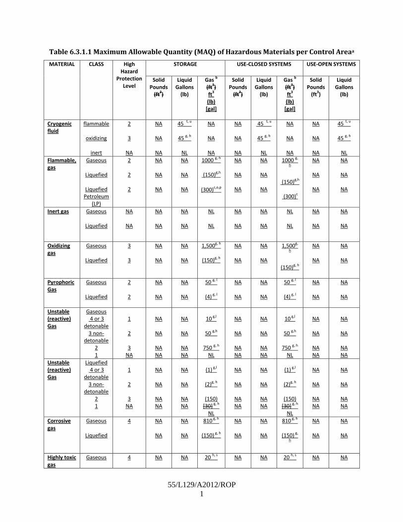
55/L129/A2012/ROP 1
Table 6.3.1.1 Maximum Allowable Quantity (MAQ) of Hazardous Materials per Control Areaa
MATERIAL CLASS High Hazard
Protection Level
STORAGE USE-CLOSED SYSTEMS USE-OPEN SYSTEMS
Solid Pounds
(ft3)
Liquid Gallons
(lb)
Gas b (ft3) ft3
(lb)
Solid Pounds
(ft3)
[gal]
Liquid Gallons
(lb)
Gas b (ft3) ft3
(lb)
[gal]
Solid Pounds
(ft3)
Liquid Gallons
(lb)
Cryogenic fluid
flammable
oxidizing
inert
2
3
NA
NA
NA
NA
45 t, u
45 g, h
NL
NA
NA
NA
NA
NA
NA
45 t, u
45 g, h
NL
NA
NA
NA
NA
NA
NA
45 t, u
45 g, h
NL
Flammable, gas
Gaseous
Liquefied
Liquefied Petroleum
(LP)
2
2
2
NA
NA
NA
NA
NA
NA
1000 g, h
(150)g,h
(300)c,o,p
NA
NA
NA
NA
NA
NA
1000 g,
h
(150)g,h
(300)c
NA
NA
NA
NA
NA
NA
Gaseous Inert gas
Liquefied
NA
NA
NA
NA
NA
NA
NL
NL
NA
NA
NA
NA
NL
NL
NA
NA
NA
NA
Oxidizing gas
Gaseous
Liquefied
3
3
NA
NA
NA
NA
1,500g, h
(150)g, h
NA
NA
NA
NA
1,500g,
h
(150)g, h
NA
NA
NA
NA
Pyrophoric Gas
Gaseous
Liquefied
2
2
NA
NA
NA
NA
50 g, l
(4) g, l
NA
NA
NA
NA
50 g, l
(4) g, l
NA
NA
NA
NA
Unstable (reactive) Gas
Gaseous 4 or 3
detonable 3 non-
detonable 2 1
1
2
3
NA
NA
NA
NA
NA
NA
NA
NA
NA
10 g,l
50 g,h
NL 750 g, h
NA
NA
NA
NA
NA
NA
NA
NA
10 g,l
50 g,h
NL 750 g, h
NA
NA
NA NA
NA
NA
NA NA
Liquefied Unstable (reactive) Gas
4 or 3 detonable
3 non-detonable
2 1
1
2
3
NA
NA
NA
NA
NA
NA
NA
NA
NA
(1) g,l
(2)g, h
(150)
[30] g, h NL
NA
NA
NA
NA
NA
NA
NA
NA
(1) g,l
(2)g, h
(150)
[30] g, h NL
NA
NA
NA NA
NA
NA
NA NA
Gaseous Corrosive gas
Liquefied
4
NA
NA
NA 810 g, h
NA
(150) g, h
NA
NA
NA 810 g, h
NA
(150) g,
h
NA
NA
NA
NA
Gaseous Highly toxic gas
4
NA
NA 20 h, s
NA
NA 20 h, s
NA
NA

55/L129/A2012/ROP 2
Liquefied
NA (4) h, s NA
NA
NA (4) h, s
NA
NA
Gaseous Toxic gas
Liquefied
4
NA
NA
NA 810 g, h
NA
(150) g, h
NA
NA
NA
NA
810 g, h
(150) g,
h
NA
NA
NA
NA
a See 60.1.26.2 for exceptions to tabular amounts. For use of control areas, see 60.2.3. Table values in parentheses or brackets correspond to the unit name in parentheses or brackets at the top of the column. The aggregate quantity in use and storage is not permitted to exceed the quantity listed for storage. In addition, quantities in specific occupancies are not permitted to exceed the limits in 60.1.26.2. in the building code. b Measured at NTP or 70 °F (21°C) and 14.7 psi (101.3 kPa). c Inside a building, the maximum capacity of a combustible liquid storage system that is connected to a fuel-oil piping system is permitted to be 660 gal (2,500L), provided that such system conforms to NFPA 31 Standard for the Installation of Oil-Burning Equipment. See NFPA 58, Liquefied Petroleum Gas Code for requirements for liquefied petroleum gases (LPG). LPG is not within the scope of NFPA 55. d Flammable and combustible liquids and flammable gases in the fuel tanks of mobile equipment or vehicles are permitted to exceed the MAQ where the equipment is stored and operated in accordance with this Code the fire code. e In storage, low, and ordinary hazard occupancies, the storage of Class II combustible liquids is required to be limited to a maximum quantity of 1,375 gal (5204L); Class IIIA combustible liquids are required to be limited to a maximum quantity of 13,750 gal (52,044L) where stored in accordance with all the requirements in NFPA 30 for general-purpose warehouses. f The quantity of fuel in aircraft in hangars is required to be in accordance with NFPA 409, Standard on Aircraft Hangars. g Quantities are permitted to be increased 100 percent where stored or used in approved cabinets, gas cabinets, exhausted enclosures, gas rooms, explosives magazines, or safety cans, as appropriate for the material stored., in accordance with NFPA 1. Where Footnote h also applies, the increase for both footnotes is permitted to be applied accumulatively. h Maximum quantities are permitted to be increased 100 percent in buildings equipped throughout with an automatic sprinkler system in accordance with NFPA 13, Standard for the Installation of Sprinkler Systems. Where Footnote g also applies, the increase for both footnotes is permitted to be applied accumulatively. i The permitted quantities are not limited in a building equipped throughout with an automatic sprinkler system in accordance with NFPA 13. j A maximum quantity of 200 lb (91 kg)of solid or 20 gal (76 L) of liquid Class 3 oxidizers is permitted where such materials are necessary for maintenance purposes, operation, or sanitation of equipment. Storage containers and the manner of storage are required to be approved. k Unless the actual weight of the pyrotechnic composition of the consumer fireworks, 1.4G, is known, 25 percent of the gross weight of the fireworks, including packaging, is permitted to be used to determine the weight of the fireworks for the purpose of this table. l Permitted only in buildings equipped throughout with an automatic sprinkler system in accordance with NFPA 13. m Maximum quantities of black powder, smokeless propellant, and small arms primers stored or displayed in mercantile occupancies or stored in one- or two-family dwellings are permitted to exceed the amount specified by this table where such storage complies with the requirements of NFPA 495, Explosive Materials Code, Chapter 13. n In lieu of the maximum allowable quantity limit per control area, the maximum aggregate quantity per building of special explosive devices in industrial, mercantile, and storage occupancies is required to be shall be limited to 50 lb. o Additional storage locations are required to be separated by a minimum of 300 ft (92 m). p In mercantile occupancies, storage of LP-Gas is limited to a maximum of 200 lb (91 kg) in nominal 1 lb (0.45 kg) LP-Gas Containers. q In storage, low, and ordinary hazard occupancies, the storage of Class IA flammable liquids is not permitted, and the combination storage of Class IB and Class IC flammable liquids is required to be

55/L129/A2012/ROP 3
limited to a maximum quantity of 660 gal (2,500 L) where stored in accordance with all the requirements in NFPA 30 for general-purpose warehouses. r Containing not more than the maximum allowable quantity per control area of Class I-A, Class I-B, or Class I-C flammable liquids. s A single cylinder containing 150 lb or less of anhydrous ammonia in a single control area in a nonsprinklered building is considered to be the maximum allowable quantity. Two cylinders, each containing 150 lb or less, in a single control area is considered to be the maximum allowable quantity, provided that the building is equipped throughout with an automatic sprinkler system in accordance with NFPA 13. t sAllowed only where stored or used in gas rooms or in approved, exhausted gas cabinets or exhausted enclosures, as specified in this Code. t None allowed in unsprinklered buildings unless stored or used in gas rooms or in approved gas cabinets or exhausted enclosures, as specified in this Code. u With pressure-relief devices for stationary or portable containers vented directly outdoors or to an exhaust hood. [5000: Table 34.1.3.1]
Report on Proposals – June 2012 NFPA 55_______________________________________________________________________________________________55- Log #32
_______________________________________________________________________________________________John J. Anicello, Airgas Inc.
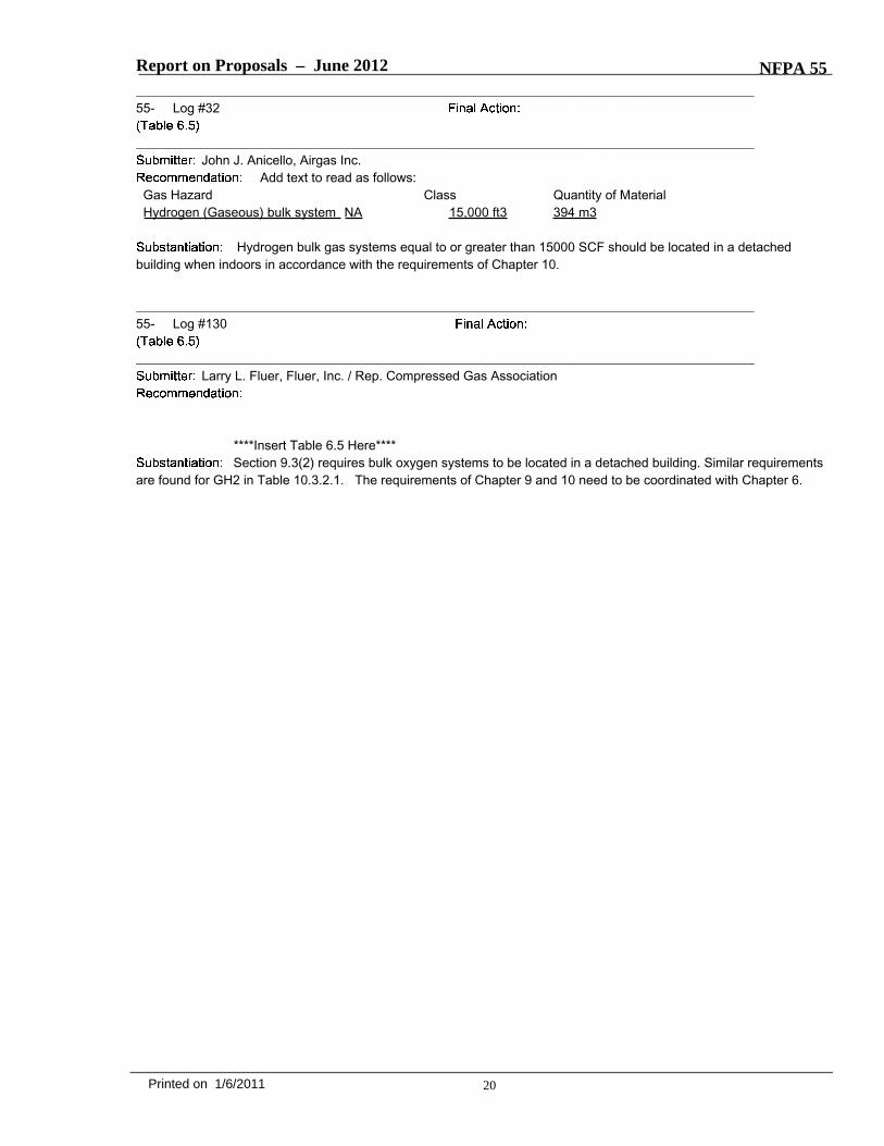
Add text to read as follows:Gas Hazard Class Quantity of MaterialHydrogen (Gaseous) bulk system NA 15,000 ft3 394 m3
Hydrogen bulk gas systems equal to or greater than 15000 SCF should be located in a detachedbuilding when indoors in accordance with the requirements of Chapter 10.
_______________________________________________________________________________________________55- Log #130
_______________________________________________________________________________________________Larry L. Fluer, Fluer, Inc. / Rep. Compressed Gas Association
****Insert Table 6.5 Here****Section 9.3(2) requires bulk oxygen systems to be located in a detached building. Similar requirements
are found for GH2 in Table 10.3.2.1. The requirements of Chapter 9 and 10 need to be coordinated with Chapter 6.
20Printed on 1/6/2011

55/L130/Tb 6.5/A2010/ROP
Table 6.5 Detached Buildings Required Where Quantity of Material Exceeds Amount Shown
Quantity of Material Gas Hazard Class ft3 m3
Bulk oxygen systems NA 20,000 570 Bulk hydrogen compressed gas systems
NA 15,000 425
Unstable reactive (detonable)
4 or 3 Quantity thresholds for gases requiring special provisions*
Unstable reactive (nondetonable)
3 2,000 57
Unstable reactive (nondetonable)
2 10,000 283
Pyrophoric gas NA 2,000 57 NA: Not applicable. *See Table 6.3.1.1.

Report on Proposals – June 2012 NFPA 55_______________________________________________________________________________________________55- Log #73
_______________________________________________________________________________________________Larry L. Fluer, Fluer, Inc. / Rep. Compressed Gas Association
Revise text to read as follows:For such storage or use areas to be regulated as outdoor storage or use, compliance with 6.5.3 and 6.5.4 shall
be required.
For other than explosive materials and hazardous materials presenting a detonation hazard, a weatherprotection structure shall be permitted to be used for sheltering outdoor storage or use areas, without requiring suchareas to be classified as indoor storage or use.
For such storage or use areas Weather protected areas constructed in accordance with 6.6.3 to shall beregulated as outdoor storage or use., compliance with conditions in 6.5.3 and through 6.5.4 shall be required.
Where storage or use areas are provided with weather protection that does not comply with theseconditions, Weather protected areas that are not constructed in accordance with 6.6.3 the storage or use area shall beregulated as an indoor storage or use area.
Buildings or structures used for weather protection shall be in accordance with the following:(1) The building or structure shall be constructed of non-combustible materials.(2) Supports and shall not obstruct more than one side or more than 25 percent of the open perimeter of the
storage or use area.(3) The building or structure shall be limited to a maximum area of 1500 ft2 with increases in area allowed by the
building code based on occupancy and type of construction.
(4) 6.6.2.5. The distance from the structure constructed as weather protection and the structural supports tobuildings, lot lines, public ways or means of egress to a public way shall not be less than the distance required for anoutside hazardous material storage or use area without weather protection based on the hazard classification of thematerials contained.(5) Where the weather protection structure is constructed of noncombustible materials, Reductions in the
separation distance shall be permitted based on the use of fire barrier walls where permitted for specific materials inaccordance with the requirements of Chapters 7 through 11.
The provisions for weather protection are inappropriately placed as subparagraphs to Section 6.5 fordetached buildings. Buildings or structures used for weather protection may or may not be independent detachedstructures. For example, the typical cylinder dock may abut a building used for the production or storage of compressedgas. It is part of the building which is sheltered by overhead cover, but considered as outdoor storage in order toprovide relief from requirements such as mechanical ventilation, explosion control and sprinkler systems in some cases.In order to “earn” the exemption, the area must be maintained substantially open to the surrounds.The building codes allow for this dispensation providing the weather protected area is limited in size and ofnon-combustible construction. The I-Codes have traditionally limited the area occupied as weather protection to 1500 sfas a means to grant dispensation from other requirements of the building code affecting sprinkler systems (in somecases), mechanical ventilation systems and explosion control. Allowances are made for area increase based oncomparable areas of any building including the use of sprinkler systems (when otherwise not required) and streetfrontage based on fire separation distance. Approval of this proposal will correlate the concept of construction with therequirements listed in the IBC/IFC with the exception of the clarifications made. To determine the allowable areaincreases the construction type and occupancy of the sheltered area must first be determined.Weather protection cannot be obstructed by enclosing it with perimeter walls that substantially block the free
movement of air, and accessibility. On the other hand limited obstructions within a given set of prescriptive controls areacceptable. For example, a cylinder dock on the exterior of the building is allowed to abut the exterior building wallproviding the three remaining walls are open to the exterior. The provisions also allow for the obstruction of multiplewalls, providing that the total area of the perimeter walls that are obstructed does not exceed 25% of the total openperimeter area. To determine this mathematically the designer would calculate the aggregate perimeter area of all opensides of the building or structure used for weather protection and then demonstrate that obstructed areas (covered byabutting buildings or partial walls) do not exceed 25% of the aggregate area.Section 6.5.1 has been deleted as it is redundant to Section 6.6.2 (old Section 6.5.2.2). It had been improperly placed
as a subsection to 6.5 which is a requirement for detached buildings. Buildings and structures constructed as weather
21Printed on 1/6/2011

Report on Proposals – June 2012 NFPA 55protection can be detached buildings or they can be attached to a building. The issue is not whether they are attachedor detached, the issue is whether the sheltered area is considered to be indoors or outdoors.
_______________________________________________________________________________________________55- Log #74
_______________________________________________________________________________________________Larry L. Fluer, Fluer, Inc. / Rep. Compressed Gas Association
Revise text to read as follows:The requirements of 6.6.1.1 shall not apply where emergency power is provided in accordance with 6.6.2 and
, .
Section 6.6.2 provides requirements in addition to those prescribed by NFPA 70. Adding 6.6.2 as across reference in 6.6.1.2 is an editorial function.
_______________________________________________________________________________________________55- Log #75
_______________________________________________________________________________________________Larry L. Fluer, Fluer, Inc. / Rep. Compressed Gas Association
Revise text to read as follows:
Explosion control shall be provided as required by Table 6.8 in accordance with NFPA 68,or NFPA 69, , where amounts of
compressed gases in storage or use exceed the quantity thresholds requiring special provisions.NFPA 68, , provides more information on this subject.
NFPA 68 has been converted from a recommended practice to a Standard, and as such it isappropriate to refer to this document in the body of the code. Table 6.8 provides for the use of venting as anappropriate means to address the requirements for explosion control. Moving the requirements from an informationalannex to the body of the code coordinates the concept in NFPA 55 with that used in NFPA 2 for hydrogen. It isappropriate for all flammable gases when explosion control is required through the use of deflagration venting.
_______________________________________________________________________________________________55- Log #23
_______________________________________________________________________________________________Tom Christman, Caryville, TN
Revised text to read as follows:When sprinkler protection is provided, the area in which compressed gases or cryogenic fluids are stored or
used shall be protected with a sprinkler system designed to be not less than that required by NFPA 13, Standard for theInstallation of Sprinkler Systems, for Ordinary Hazard Group 2. with a minimum design area of 3000 ft2 (278.7 m2).
The code provides no justification on why the design area needs to be increased to a minimum of3000 sq ft. There is no increased fire risk from any of the inert gases which may be present in an area. Flammablegases are covered by Section 6.9.2.2 To stipulate a mandated minimum design area without noting the specific hazardor reason with annex material seems to be arbitrary. The designer of the system should be allowed to protect the hazardas noted with the classification of the system as Ordinary Hazard, Group 2. The Code should not restrict a designer to aminimum design area without substantial justification. If this Code has predetermined that the storage or use of anycompressed gas is an Ordinary Hazard, Group 2 risk, the designer should have the latitude to follow the Density/AreaCurves as noted in NFPA 13 for the applicable hazard.
22Printed on 1/6/2011

Report on Proposals – June 2012 NFPA 55_______________________________________________________________________________________________55- Log #24
_______________________________________________________________________________________________Tom Christman, Caryville, TN
Revise text to read as follows:When sprinkler protection is provided, the area in which the flammable or pyrophoric compressed gases or
cryogenic fluids are stored or used shall be protected with a sprinkler system designed to be not less than that requiredby NFPA 13, , for Extra Hazard Group 1. with a minimum design areaof 2500 ft2 (232.25 m2).
The use of flammable gases for maintenance or temporary activities such as but not limited to hot work ispermitted without classification of the sprinkler system as Extra Hazard, Group 1.
The code provides no justification on why the design area needs to be increased to a minimum of3000 sq ft. To stipulate a mandated minimum design area without noting the specific hazard or reason with annexmaterial seems to be arbitrary. The designer of the system should be allowed to protect the hazard as noted with theclassification of the system as Extra Hazard, Group 1. The Code should not restrict a designer to a minimum designarea without substantial justification. If this Code has predetermined that the storage or use of a flammable compressedgas is an Extra Hazard, Group 1 risk, the designer should have the latitude to follow the Density/Area Curves as notedin NFPA 13 for the applicable hazard.A new section is added to allow the use of compressed flammable gases within a sprinklered area without having to
classify the system as Extra Hazard, Group 1. Most facilities would generally NOT be classified as an Extra Hazard butmost facilities from time to time require hotwork to be performed to maintain the building. As the classification of thesprinkler system cannot be changed from the original design, the code needs to provide the flexibility to conductrequired work without having to install the sprinkler system as Extra Hazard.
_______________________________________________________________________________________________55- Log #25
_______________________________________________________________________________________________Andrew Minister, Battelle Pacific Northwest National Laboratory
New paragraph to 6.16.1:Electrical powered equipment shall not be installed inside of gas cabinets containing flammable gas cylinders.
Gas cabinets are not sold as listed or tested by a nationally recognized testing laboratory. I have seengas cabinets that have been modified to install electrical equipment inside of the cabinet for flow control equipment orother types of gas flow or pressure monitoring equipment. There are no current code requirements that address thehazard of electrical equipment located inside of a gas cabinet with flammable gas cylinders inside of the cabinet. In theevent of a leak or gas equipment failure, the electrical equipment presents an ignition source for the flammable gas andcould cause a fire or an explosion. The change is needed to make sure that cabinets are not modified by the installationof electrical equipment by the user.
_______________________________________________________________________________________________55- Log #42
_______________________________________________________________________________________________Robert Wichert, FCHEA, and Chris Radley, Altergy
Revise text to read as follows:6.16.4 Quantity Limits. Gas cabinets shall contain not more than three containers, cylinders, or tanks the MAQ limit
given in Table 6.3.1.1 for Gas Cabinet, Gas Room, or Exhausted Enclosure; sprinklered or unsprinklered as appropriate;for the material being stored. .
The limit of three containers, cylinders, or tanks is inappropriate since it is not related to quantity.
23Printed on 1/6/2011

Report on Proposals – June 2012 NFPA 55_______________________________________________________________________________________________55- Log #30
_______________________________________________________________________________________________John J. Anicello, Airgas Inc.
Add text to read as follows:7.1.3 Large Insulated Liquid Carbon Dioxide System. Large insulated liquid carbon dioxide systems shall be in
accordancewith the provisions of CGA G-6.1—2005, Standard for Insulated Carbon Dioxide Systems at Customer Sites.7.1.4 Large Insulated Liquid Nitrous Oxide System. Liquid insulated nitrous oxide systems shall be installed in
accordance with the provisions of G-8.1--2007, Standard for Nitrous Oxide Systems at Customer Sites.
Insulated carbon dioxide and nitrous oxide systems are not cryogenic fluids, and therefore chapter 8provisions do not apply in the current code leaving them inadequately regulated under chapter 7 provisions. CGA hasdeveloped standards for the installations of these containers and by referencing their use will bring a harmonizedminimum standard around the country.
_______________________________________________________________________________________________55- Log #76
_______________________________________________________________________________________________Larry L. Fluer, Fluer, Inc. / Rep. Compressed Gas Association
Revise text to read as follows:Compressed gas containers, cylinders, and tanks used for metal
hydride storage systems shall be designed and constructed in accordance with 7.1.5.1.
Clarification of requirements is warranted as it avoids misapplication of this section of the code. Onecould argue that 7.1.4 is only for metal hydride storage systems and that the added language is redundant and onlyeditorial, however, the use of the term has been inserted into other subsections and insertion of the language serves tobring consistency to the approach.
_______________________________________________________________________________________________55- Log #77
_______________________________________________________________________________________________Larry L. Fluer, Fluer, Inc. / Rep. Compressed Gas Association
Revise text to read as follows:Defective containers, cylinders, and tanks shall be returned to the supplier.Suppliers shall repair the containers, cylinders, and tanks, remove them from service, or dispose of them in
an approved manner.Suppliers shall ensure that defective containers, cylinders and tanks that have been repaired are evaluated
by qualified personnel to verify that the needed repairs and any required testing has been performed and that thoserepaired or tested are in a serviceable condition before returning them to service.
Repairs to pressure vessels is conducted by authorized requalifiers or testers under the requirementsof the Department of Transportation. Suppliers and third party authorized cylinder requalifiers can perform the workproviding they have been approved by DOT or similar agency (TC) for performing the required tests and/or repairs. Inthe event that the supplier is not the authorized requalifier the supplier has a responsibility to ensure that any workperformed to correct deficiencies has been performed as requested. Persons qualified to ensure that the requiredrepairs and testing has been performed include those that are familiar with the repair and requalification process.
24Printed on 1/6/2011

Report on Proposals – June 2012 NFPA 55_______________________________________________________________________________________________55- Log #78
_______________________________________________________________________________________________Larry L. Fluer, Fluer, Inc. / Rep. Compressed Gas Association
Revise text to read as follows:Containers, Cylinders, and Tanks Containing Residual Gas. Compressed gas containers, cylinders, and tanks
containing residual product shall be treated as full except when being examined, serviced, or refilled by a gasmanufacturer, authorized cylinder requalifier or distributor.
Cylinder requalifiers are in effect an extension of the supply and distribution chain where containers arereceived, segregated, examined, serviced and processed. These containers may contain compressed gases whenreceived, and the practices exercised by the suppliers including nesting, transport, security, etc. apply as the cylindersmove through the process.Section 7.1.5.4 and others provide direction to the handling of cylinders, containers and tanks that are being serviced.
The inclusion of the term in this provision works in concert with correlating changes to expand the requirements andexemptions granted to the gas manufacturers or distributers to include the category of requalifiers as those involved withcylinder servicing (other than the gas suppliers).For additional information see 49 CFR 107.805.A companion definition for “authorized cylinder requalifier” has been submitted as a separate proposal.
_______________________________________________________________________________________________55- Log #79
_______________________________________________________________________________________________Larry L. Fluer, Fluer, Inc. / Rep. Compressed Gas Association
Revise text to read as follows:Systems equipped with impressed current cathodic protection systems shall be
inspected in accordance with the requirements of the design and 7.1.4.1.12 7.1.6.2. The design limits shall be availableto the AHJ upon request.
The design limits shall be available to the AHJ upon request.The system owner shall maintain the following records to demonstrate that the cathodic protection
is in conformance with the requirements of the design:(1) The results of inspections of the system(2) The results of testing that has been completed
The reference in 7.1.6.3 to 7.1.4.1.12 is to the NEC. The appropriate reference for inspection is to7.1.6.2. The last sentence of 7.1.6.3 is a requirement for the designer and as such is not part of inspection. The lastsentence has been proposed to be added as subparagraph 7.1.6.3.1 and the following paragraph renumbered.
25Printed on 1/6/2011

Report on Proposals – June 2012 NFPA 55_______________________________________________________________________________________________55- Log #80
_______________________________________________________________________________________________Larry L. Fluer, Fluer, Inc. / Rep. Compressed Gas Association
Revise text to read as follows:Storage, use, and handling areas shall be secured against unauthorized entry.
Administrative controls shall be allowed to be used to control access to individual storage, use, and handlingareas located in secure facilities not accessible by the general public.
The goal of this requirement is to prevent unauthorized personnel or those unfamiliar with gas storagesystems from tampering with the equipment as well as to prevent the inadvertent or unauthorized removal or use ofcompressed gases from storage areas. Where the compressed gases are located in an area open to the general public,a common practice is to fence and lock the storage or use area, with access restricted to supplier and user personnel.When the storage or use is located within the user’s secure area and is not accessible by the general public, it is notalways necessary to fence or otherwise secure the individual gas storage or use areas. Personnel access patterns maystill mandate that the system be fenced, as determined by the supplier and the user.
As explained by the annex note, the primary purpose of security is to prevent tampering andunauthorized use of compressed gases by the general public. Many facilities are either fully fenced or otherwiseprovided with access control whereby only the users of these materials are permitted access. The intent of the codewas not to require that any storage or use be under lock and key or that the security provided be such that storage oruse by facility employees was hampered by security controls. It is reasonable to expect that facilities that are notaccessible by the general public have administrative procedures in place that directs the proper storage and use areasas well as specifying how these materials will be allowed to be employed. New Section 7.1.8.2.1 does not mandate theuse of administrative controls, but allows administrative controls to be used as a means to limit access. In areas notaccessible by the general public the user has a choice as to whether to provide physical barriers as a means ofprotection or to otherwise restrict access through the use of policies and procedures. This flexibility is required by thecode to address practical application of these requirements.
_______________________________________________________________________________________________55- Log #81
_______________________________________________________________________________________________Larry L. Fluer, Fluer, Inc. / Rep. Compressed Gas Association
Revise text to read as follows:At cylinder-filling plants, authorized cylinder requalifier’s facilities and distributors' warehouses, the nesting of
cylinders shall be permitted as a means to secure cylinders.
Cylinder requalifiers are in effect an extension of the supply and distribution chain where containersare received, segregated, examined, serviced and processed. Nesting is a recognized way to handle securing ofcylinders in plants and facilities handling large numbers of containers. Including authorized cylinder requalifier’s facilitiesin the use of nesting is in keeping with the practices currently employed in facilities of this nature.A companion definition for “authorized cylinder requalifier” has been submitted as a separate proposal.
26Printed on 1/6/2011

Report on Proposals – June 2012 NFPA 55_______________________________________________________________________________________________55- Log #82
_______________________________________________________________________________________________Larry L. Fluer, Fluer, Inc. / Rep. Compressed Gas Association
Add new text to read as follows:Valve protection of individual valves shall not be required to be installed on individual cylinders, containers or
tanks installed on tube trailers or similar transportable bulk gas systems equipped with manifolds that are provided witha means of physical protection that will protect the valves from physical damage when the equipment is in use.Protective systems required by DOT for over the road transport shall provide an acceptable means of protection.
Valve protection of individual valves shall not be required on cylinders, containers or tanks that comprisebulk or non-bulk gas systems where the containers are stationary, or portable equipped with manifolds, that areprovided with physical protection in accordance with 4.11 and 7.1.8.3 or other approved means. Protective systemsrequired by DOT for over the road transport shall provide an acceptable means of protection.
Section 7.1.9.1 was written as a general requirement for all compressed gases. There are instanceswhere compressed gas cylinders may be used in a form not anticipated by the code when this section was developed.Tube trailers, cylinder packs and similar arrangements conventionally are not equipped with protective caps, collars, orsimilar devices. On the other hand such equipment generally is equipped with safeguards to protect the containervalves from impact.Adding the new requirements that recognize the requirements for manifold protection can resolve the problem with
tube trailer systems. A new requirement has been established in 7.1.9.1.1 to address systems other than DOT (over theroad) type systems which may include equipment commonly known as 6 packs, 12 packs and similar items which arecomprised of cylinders equipped with a manifold that are attached to a wheeled frame. Physical protection is typicallyprovided by the framework used as a supporting structure. In addition, stationary storage/use systems are not equippedwith valve protection of the type suggested by 7.1.9.1. Systems of this nature are usually protected through the use ofSection 4.11 or 7.1.8.3. The “other approved means” is an important consideration to recognize that every possiblecircumstance cannot be addressed. Physical protection can be provided by means other than those specificallydescribed in 4.11 or 7.1.8.3. Sufficient guidance is provided to inform the user of the need and of the exceptions to beapplied.
27Printed on 1/6/2011
Report on Proposals – June 2012 NFPA 55_______________________________________________________________________________________________55- Log #83
_______________________________________________________________________________________________Larry L. Fluer, Fluer, Inc. / Rep. Compressed Gas Association
Revise text to read as follows:
Compressed gas containers, cylinders, tanks, and systems in storage or use shall be separated frommaterials and conditions that present exposure hazards to or from each other.
Compressed gas containers, cylinders, tanks, and systems in storage or use shall be separated inaccordance with 7.1.10.
Subparagraph 7.1.10.1.2 shall not apply to gases contained within closed piping systems, compressed gascontainers, cylinders, tanks, and systems in storage or use when separated in accordance with 7.1.10.
Gas containers, cylinders, and tanks shall be separated in accordance with Table7.1.10.2.
Subparagraph 7.1.10. 2 shall not apply to gases contained within closed piping systems.The distances shown in Table 7.1.10.2 shall be permitted to be reduced without limit where compressed
gas cylinders, tanks, and containers are separated by a barrier of noncombustible construction that has a fire resistancerating of at least 0.5 hour and interrupts the line of sight between the containers.
The 20 ft (6.1 m) distance shall be permitted to be reduced to 5 ft (1.5 m) where one of the gases isenclosed in a gas cabinet or without limit where both gases are enclosed in gas cabinets.
Cylinders without pressure-relief devices shall not be stored without separation from flammable andpyrophoric gases with pressure relief devices.
Spatial separation shall not be required between cylinders deemed to be incompatible that are connectedto manifolds for the purposes of filling and manufacturing procedures, assuming the prescribed controls for themanufacture of gas mixtures are in place.
As currently written Section 7.1.10.1.2 is redundant to 7.1.10.1.1. Section 7.1.10.1.3 is in effect anexception for piping systems and should be moved to become a subparagraph to 7.1.10.2 as it is misplaced. Thebalance of the statement in 7.1.10.1.3 other than that portion addressing piping systems is identical to 7.1.10.2 and it isredundant to 7.1.10.1.1.Creating a separate subsection to address piping systems clarifies the fact that the separation of individual piping
systems is not required. From a code perspective all use of compressed gas is a condition of “closed use” includingsystems where the gas may be used in a welding torch. It is quite common for gas welding equipment to have oxygenand fuel gas incorporated into a hose (an extension of the piping system) where oxygen is transported through one sideof the hose with fuel gas transported on the other.In large facilities or in multistoried buildings it is quite common to have various gases transported in piping systems in
pipe racks that contain natural gas, compressed air, oxygen, hydrogen, nitrogen/argon or other gases. The concept isnot new, rather it is being relocated to the appropriate place in the code.
28Printed on 1/6/2011

Report on Proposals – June 2012 NFPA 55_______________________________________________________________________________________________55- Log #37
_______________________________________________________________________________________________Glenn Mahnken, FM Global
Add new text to read as follows:7.1.10.4 . Compressed gas cylinders shall not be
stored indoors within 20 ft of combustible storage or combustible construction unless the storage area is provided withadequate automatic sprinkler protection.7.1.10.5* . Compressed gas cylinders shall not be stored indoors in
areas exposed to flammable liquids storage or to operations where flammable liquid spills and resulting fires mayexpose the cylinders.*A 7.1.10.3.5 Curbing and emergency drainage may be used to prevent exposure to flammable liquids spills if
cylinders are located at least 20 ft from the curbing.These exposures to indoor cylinder storage are not clearly addressed by the current codes. Indoor
fires involving combustible storage, construction and flammable liquids can grow rapidly. Indoor locations may alsohinder manual fire-fighting from cooling the cylinders, resulting in excessive heating of the cylinders. Sprinklers andspace separation will help to reduce the exposures to the cylinders.
_______________________________________________________________________________________________55- Log #84
_______________________________________________________________________________________________Larry L. Fluer, Fluer, Inc. / Rep. Compressed Gas Association
Add new text to read as follows:Compressed gas containers, cylinders, and tanks, whether full or partially full, shall
not be exposed to temperatures exceeding 125°F (52°C) or subambient (low) temperatures unless designed for useunder such exposure.
Compressed gas containers, cylinders and tanks that have not been designed for use under elevatedtemperature conditions shall not be exposed to direct sunlight out-of-doors where ambient temperatures exceed 125°F(52°C). The use of a weather protected structure or shaded environment for storage or use shall be permitted as ameans to protect against direct exposure to sunlight.
The filling density for compressed gases is related to temperature and pressure. Filling densities andpressures are generally determined at 130°F. The 125°F (52°C) limitation provides a margin of safety to users ofgaseous materials. When ambient temperatures exceed 125°F, and containers are exposed to direct sunlight, it ispossible to exceed the 130°F threshold temperature limit internally causing containers to become over-pressurized andleak, pressure relief valves to release, or in the case of liquefied gas to expand to a point where the container may besubject to extreme hydraulic overpressure. In areas where ambient temperatures are expected to exceed 125°Fcontainers stored or used out of doors should be under weather protection, moved inside to a cooler environment orotherwise provided with shade to avoid direct contact with the rays of the sun.
29Printed on 1/6/2011

Report on Proposals – June 2012 NFPA 55_______________________________________________________________________________________________55- Log #85
_______________________________________________________________________________________________Larry L. Fluer, Fluer, Inc. / Rep. Compressed Gas Association
Add new text to read as follows:. Compressed gas containers, cylinders, and tanks, shall not be placed
where they could be a part of an electrical circuit.Electrical devices mounted on compressed gas piping, cylinders, containers or tanks shall be installed,
grounded and bonded in accordance with the methods specified in NFPA 70, National Electric Code (NEC).Electrical devices can include pressure transducers, signal transmitters, shut off controls and similar
devices. Some of these devices may be non-incendive and suitable for use in hazardous areas. Flammability of gasesis not the only concern with respect to electrical circuits as piping serving systems in uses can act as conductors ofelectrical energy exposing unrelated portions of the system to electrical hazards if improperly installed.
To allow the mounting of electrical devices on piping cylinders, containers or tanks provided they areinstalled in accordance with the NEC.
_______________________________________________________________________________________________55- Log #86
_______________________________________________________________________________________________Larry L. Fluer, Fluer, Inc. / Rep. Compressed Gas Association
Revise text to read as follows:
Accessible manual valves or automatic remotely activated fail-safe emergency shutoff valves shall beprovided to shut off the flow of gas in case of emergency. and clearly marked.
Emergency shutoff valves on a bulk source or piping systems serving the bulk supply shall be identifiedby means of a sign.
Emergency shutoffs shall be located at the point of use and at the tank, cylinder, or bulk source, and at thepoint where the system piping enters the building.
Accessible manual or automatic emergency shutoff valves shall be provided to shut off the cryogenicfluid supply in case of emergency.
Emergency shutoff valves on a bulk source or piping systems serving the bulk supply shall be identified by meansof a sign.
A Emergency shutoff valves shall be located at the point of use, at the source of supply and at the pointwhere the system piping enters the building.
The approach to providing emergency shutoff valves should be consistently applied as generalrequirements of Chapters 7 and 8. The terms “Emergency Shutoff Valve, Manual Emergency Shutoff Valve andAutomatic Emergency Shutoff Valve “ are defined terms. Automatic Emergency Shutoff Valves are required, bydefinition, to be of a fail-safe design. These valve can be activated by either automatic or manual means.Signage is required for those shutoff systems serving the bulk supply to provide for ready identification. Having a
shutoff at each point of use is conventional and the addition of signage is not always appropriate. For example, if theshutoff valve is a cylinder valve the shutoff may be obvious.A similar code change was accepted into the ROC draft of NFPA 2. Accepting this change will correlate NFPA 2 and
55 in concept except that NFPA 2 uses the terms [GH2 or LH2] in liqu of gas or cryogenic fluid where appropriate.
30Printed on 1/6/2011

Report on Proposals – June 2012 NFPA 55_______________________________________________________________________________________________55- Log #88
_______________________________________________________________________________________________Larry L. Fluer, Fluer, Inc. / Rep. Compressed Gas Association
Revise text to read as follows:Where compressed gases or liquids having a hazard ranking in one or more of the following hazard
classes in accordance with NFPA 704,, are carried in pressurized piping above a gauge pressure of 15 psi (103 kPa), an approved means of leak
detection and emergency shutoff or excess flow control shall be provided:(1) Health hazard Class 3 or Class 4(2) Flammability Class 4(3) Reactivity Class 3 or Class 4
The current wording has been interpreted to mean that the materials requiring excess flow control beclassified as having all three of the properties indicated. Clarification is warranted so that the user understands thatgases in any of the hazard classes designated is required to comply with the requirements for excess flow control.
_______________________________________________________________________________________________55- Log #87
_______________________________________________________________________________________________Larry L. Fluer, Fluer, Inc. / Rep. Compressed Gas Association
Revise text to read as follows:Where compressed gases or liquids having a hazard ranking of the following in accordance with NFPA
704, , are carried inpressurized piping above a gauge pressure of 15 psi (103 kPa), an approved means of leak detection and emergencyshutoff or excess flow control shall be provided:(1) Health hazard Class 3 or Class 4(2) Flammability Class 4(3) Reactivity Class 3 or Class 4
An approved means of leak detection and emergency shutoff is one way of meeting the requirements forexcess flow control. Bulk cryogenic fluids are not subject to the requirements for excess flow control based on a healthhazard ranking due to cold temperature when installed in accordance with the requirements of Chapters 8 or 9. Bulkcryogenic fluids that are vaporized and distributed as a compressed gas downstream of the source valve are subject tothe requirements for excess flow control if the gas has either a health hazard ranking of Class 3 or 4 based oncorrosivity or toxicity, a flammability hazard ranking of Class 4, or a reactivity ranking of Class 3 or 4.
Chapter 7 covers compressed gases, not cryogenic fluids. The use of the word “liquids” may cause theuser to believe that cryogenic fluids, which are assigned health hazard rankings of 3, because of the low temperaturerequire excess flow protection on the bulk source when a bulk cryogenic fluid system supplies gas (for example, a liquidnitrogen tank supplying gaseous nitrogen). On the other hand a cryogenic fluid that may have a health hazard rating ofClass 3 or 4 based on corrosivity or toxicity a flammability ranking of Class 4 or a reactivity ranking of Class 3 or 4 wouldbe required to be equipped with excess flow control. Excess flow control for cryogenic fluid systems where the gas isvaporized is typically located downstream of the source valve which is normally in close proximity to where the cryogenis vaporized and converted from the liquid phase to the gaseous phase. Clarifications have been added withmodifications to the annex note that provide guidance to the user in this regard.
31Printed on 1/6/2011

Report on Proposals – June 2012 NFPA 55_______________________________________________________________________________________________55- Log #89
_______________________________________________________________________________________________Larry L. Fluer, Fluer, Inc. / Rep. Compressed Gas Association
1. Revise Section 7.3.1.12.1.2 as follows:Where the piping originates from a bulk source, the
excess flow control shall be located at the bulk source at a point immediately downstream of the source valve.When distributed systems are employed the excess flow control system located at the bulk source may
be sized to operate at a release rate greater than any single point of use or branch connection. Additional points ofexcess flow control may be required throughout the system in order to provide shut down in the event of a failure in anysingle system branch. Such systems will generally be designed to operate when flow exceeds the capacity of thepoint(s) of use served.2. In Figures A.3.3.12(d) and (e) relocate the excess flow valve (EFV) to a point downstream of the Source Valve (SV).
The design of the excess flow control system is the responsibility of the user. The rate of gasconsumption and required operating pressures are variable and dependent on user demands on the system. The intentof the excess flow control system is to limit release in the event of a rupture or breach of the piping system.The drawings in Figure A.3.3.12(d) and (e) should be revised to locate the excess flow valve downstream of the source
valve.
_______________________________________________________________________________________________55- Log #38
_______________________________________________________________________________________________Glenn Mahnken, FM Global
Add new text to read as follows:7.3.1.12.1.3 Where leak detection is used as a means of excess flow control, the leak detection means shall be
provided at both the bulk source and end use areas.Clarifies that leak detection is needed on both sides of the source valve.
_______________________________________________________________________________________________55- Log #90
_______________________________________________________________________________________________Larry L. Fluer, Fluer, Inc. / Rep. Compressed Gas Association
Revise text to read as follows:The controls required by 7.3.1.12 shall not be required for the following:
(1) Piping for inlet connections designed to prevent backflow at the source(2) Piping for pressure relief devices(3) Where the source of the gas is not in excess of the quantity threshold indicated in Table 6.3.1.1(4)* Systems equipped with emergency shutdown controls used to transfer a batch load to or from a delivery vehicle to
a storage system or from a delivery vehicle or storage system to process operations.A batch load is typically the entire quantity or a substantial quantity of the material in the vessel used to
initiate the transfer. The rapid transfer of a large quantity of material from delivery vehicles into storage tanks or transfersystems where the product is transferred into a process would trip conventional excess flow control systems. Examplesof these transfer operations typically involve the delivery of bulk product via a transport vehicle where the material istransferred by pump or pressure from the delivery vessel to the storage vessel. An example of such a transfer for aprocess operation might be the transfer of an entire load of hydrogen as a batch from either a storage tank or a deliveryvehicle for a hydrogenation reaction.
None given.
32Printed on 1/6/2011

Report on Proposals – June 2012 NFPA 55_______________________________________________________________________________________________55- Log #92
_______________________________________________________________________________________________Larry L. Fluer, Fluer, Inc. / Rep. Compressed Gas Association
Revise text to read as follows:The outdoor storage or use of non-bulk flammable compressed gas shall be located
from lot lines, public streets, public alleys, public ways, or buildings not associated with the manufacture or distribution ofsuch gases in accordance with Table 7.6.2.
Table 7.6.2 was developed for flammable gases other than bulk, i.e., non-bulk. The addition of theterm “non-bulk” in the charging language is needed as section titles or table titles are not regulatory by nature.
33Printed on 1/6/2011

Report on Proposals – June 2012 NFPA 55_______________________________________________________________________________________________55- Log #137
_______________________________________________________________________________________________Larry L. Fluer, Fluer, Inc.
1. Revise Section 7.6.2.1 as follows:7.6.2.1 Bulk hydrogen gas installations shall be in accordance with Table 10.3.2.2.1(a) and Table 10.3.2.2.1(b).
Chapter 10.2. Delete Section 7.6.2.5.1 in its entirety (See NFPA Errata #1).
Bulk hydrogen gas installations shall be separated from building openings in accordance with Table10.3.2.2.1(a) and Table 10.3.2.2.1(b).3. Relocate Section 10.4.6 to Section 7.6.3 and renumber the following sections.
Hydrogen systems of less than 3500 scf (99 m3) and greater than the MAQ, where located insidebuildings, shall be located in the building so that the system will be as follows:(1) In a ventilated area in accordance with the provisions of Section 6.15(2) Separated from incompatible materials in accordance with the provisions of 7.1.10.2(3) A distance of 25 ft (7.6 m) from open flames and other sources of ignition(4) A distance of 50 ft (15 m) from intakes of ventilation, air-conditioning equipment, and air compressors(a) The distance shall be permitted to be reduced to 10 ft (3.1 m) where the room or area is protected by a listed
detection system per Article 500.7(K) of , , and the detection system shuts down thefuel supply in the event of a leak that results in a concentration that exceeds 25 percent of the LFL.(b) Isolation valves used to isolate the fuel supply shall be of a fail-safe design.(5) A distance of 50 ft (15 m) from other flammable gas storage(6) Protected against damage in accordance with the provisions of 7.1.8.3
More than one system of 3500 scf (99 m3) or less shall be permitted to be installed in the sameroom or area, provided the systems are separated by at least 50 ft (15 m) or a full-height fire-resistive partition having aminimum fire resistance rating of 2 hours is located between the systems.
The separation distance between multiple systems of 3500 scf (99 m3) or less shall be permittedto be reduced to 25 ft (7.6 m) in buildings where the space between storage areas is free of combustible materials andprotected with a sprinkler system designed for Extra Hazard, Group 1 in accordance with the requirements of Section6.9.
Chapter 10 is applicable to bulk gas systems. Proposals have been introduced to increase the quantitythreshold used to define bulk hydrogen compressed gas systems from 400 cubic feet to 5000 cubic feet which will alignthe threshold level with Section 7.6.2.2 for other flammable gases. Section 7.6.2.1 has been revised to refer the user toChapter 10 for requirements for bulk gas systems. Section 7.6.2.5.1 das been deleted as bulk hydrogen is proposed tobe regulated by Chapter 10.A separate proposal has been submitted to revise Chapter 10 to regulate bulk gas systems. The proposed revision of
Chapter 10 to have it apply only to bulk GH2 systems necessitates requirements for indoor non-bulk systems currentlyfound in Section 10.4.6 to be relocated to Chapter 7.The actions taken by the IMG TG on this proposal should be consistent with respect to the proposals affecting the
reorganization of Chapter 10.
34Printed on 1/6/2011
Report on Proposals – June 2012 NFPA 55_______________________________________________________________________________________________55- Log #11
_______________________________________________________________________________________________Mindy Wang, Ampco Safety Tools
New text to read as follows:7.6.3.3 Mechanical Spark. Friction heat or impact spark shall be controlled. Hand tools used in areas that cannot be
purged free of flammable concentrations shall be spark resistant.
● Although there are many ventilation/purging provisions within NFPA 55, a flammable environment can develop ascould be expected with ventilation or equipment malfunction. Flammable gas such as hydrogen gas is colorless,odorless, tasteless and therefore not detectable by the human senses. In the event of ventilation or equipment failure,flammable concentration can quickly accumulate that is not detectable by the human senses.● Non-sparking hand tools are used to guard against mechanical sparks such as impact and friction sparks, which are
both a potential ignition source in flammable environments. Hand tools used on flammable gas cylinders or systems areused in a torque application, i.e. tools will make contact in a rubbing action. Friction sparks are generated from rubbingor surface contact between steel and other materials; they can generate friction sparks and therefore create an ignitionhazard in a flammable environment. This occurs when metal parts of the steel tool rub against another hard surface.Impact sparks, however, are created by a steel object being struck or dropped on another hard surface.
● In a document entitled, Frictional Sparking, Martin Sheldon stated that “It is well known that the sharpening of steeltools on a grindstone is accompanied by showers of sparks.” Sheldon went on to say “frictional heating and sparkoccurs when two solid bodies come into contact with each other, because of microscopic surface irregularities, they donot touch over the whole of their surfaces but only at a relative few spots. At the actual contact spots adhesion occursbetween the two bodies and if they are moved relative to each other the work necessary to overcome this adhesion isconverted into heat, raising the temperature of the bodies…..As the contact spots are forced apart fragments of thematerials may be broken off and projected into the surroundings…These small particles of material have arisen from theareas where work was expended. If these particles are heated sufficiently the glowing particles will appear as frictionalsparks.”● A test by R.E. Bruderer, Ignition Properties of Mechanically Sparks and Hot Surfaces in Dust/Air Mixtures, reported
that “systematic tests with steel friction sparks resulted in the ignition of the easily ignitable flammable gases (hydrogen)and combustible dusts.”● M.J. Burgess and R.V. Wheeler also reported immediate ignitions of hydrogen-air obtained by rubbing mild steel on
mild steel at 2 meter per second in Safety Mines Research Bd. Paper 46, H.M.S.O.● NFPA 30, Flammable and Combustible Liquids, Chapter 6, section 6.5.1 lists frictional heat or sparks as sources of
ignition of flammable vapors and precaution shall be taken to control ignition sources.● OSHA Flammable and Combustible Liquids regulation, 29 CFR Parts 1910.106(b)(6) states that precaution shall be
taken to eliminate or control sources of ignitions including frictional heat and mechanical sparks to prevent the ignition offlammable vapors.● In Frictional Sparking, Martin Sheldon reported steel friction sparks are incandescent particles at temperatures
around 1500°C/2732°F● NFPA 921, Guide for Fire and Explosion Investigations 2008 Edition, Chapter 5 Basic Fire Science Table 5.76.1.1
Reported Burning and Sparking Temperature of Selected Ignition Sources under Mechanical Sparks lists a Steel toolspark temperature at 2550°F.● Minimum ignition temperatures(MIT) for flammable gases are reportedly less than 2550°F, for example, MIT for
hydrogen is 968°F, 824°F for gasoline, 440°F for kerosene, 959°F for ethane, 380°F for ethyl ether, 689°F for ethylalcohol, 896°F for toluene. Spark temperature of steel hand tools far exceeds the minimum ignition temperature offlammable gases.● A test conducted by W. Bartknecht, Ignition Capability of Hot Surfaces and Mechanically Generated Sparks in
Flammable Gas and Dust/Air Mixtures showed that if steel is rubbed against steel for a longer duration, (0.5-2.0seconds) then friction sparks are generated which are much more ignition efficient. At ignition temperature 400°C(752°F), the electrical equivalent energy by steel friction sparks range from 10mJ to 100mJ. Reported minimum ignitionenergy (MIE) for most flammable gases is less than 10milijoules(mJ), for example, MIE for hydrogen is 0.017mJ, 0.3mJfor methane, 0.25mJ for ethane, 0.017mJ for gasoline, 0.2mJ for ethyl ether, 2.5mJ for toluene. Power density of frictionsparks from steel rubbed against steel also far exceeds the minimum ignition energy of flammable gases.● When working with flammable gases, a potential hazard arises because of the possibility that sparks produced by
35Printed on 1/6/2011

Report on Proposals – June 2012 NFPA 55steel or iron tools can become an ignition source.● Recognizing the potential for steel tools to be an ignition source in flammable environments, the Occupational Safety
& Health Administration (OSHA) provides guidance in booklet 3080 Hand and Power Tools, 2002 revised, “iron andsteel hand tools may produce sparks that can be an ignition source around flammable substances. Where this hazardexists, spark-resistant tools should be used.”● Handbook of Compressed Gases by Compress Gas Association, 4th edition, page 28, states that “Nonsparking tools
must be used when working with or on flammable compressed gas cylinder/systems.”● Manufacturers of flammable gases regularly require the use of “non-sparking” tools under Handling and Storage
section in the MSDS’s for their products. A few examples: Praxair, Linde Gas, Airgas, Canexus, and Calgaz
● This sample of OSHA documented accidents illustrates that accidents do happen when proper safety measures arenot taken to guard against friction sparks from steel tools.● Listed as accident#82 on dust incident data compiled by the Chemical Safety Board(CSB), an explosion resulted as
a spark created by a worker with an Allen wrench who was turning a screw to adjust a machine. The spark ignited somepropellant dust and a vacuum system carried the fire another room where a barrel of dust exploded.● OSHA inspection# 124728437, employee #1 and a coworker, both maintenance mechanics, were working in a 30 in.
by 36 in. manhole at a Space Age Fuel gas station in Gresham, OR. Employee #1 was trying to change a fuel pump,while the coworker watched from outside the manhole. Employee #1 was using an Allen wrench to loosen the bolts onthe fuel pump lead when he apparently created a spark that ignited the gas fumes in the manhole, causing an explosion.Employee #1 suffered burns to his face, hands, arms, and legs. He was transported to hospital for treatment.● OSHA inspection# 126764497, employee #1 was performing maintenance work on equipment used to make ignition
caps for automotive air bags. He ran into some problems and called maintenance, but instead of waiting for them toarrive, he dismantled and attempted to reassemble the parts. In the process, he put in a part upside down. The part hadfour screws, and while two of them were still able to be installed, the other two no longer matched with their holes.Unaware that the part was upside down, Employee #1 tried to force one of the screws in at an angle. The frictionresulting from this effort ignited the cap's residual explosive material. Flames flashed up the sleeve of Employee #1'ssmock and he sustained third-degree burns to his arm.● OSHA inspection# 309946457, employee #1 was working in the hydrogenation area when he removed the lid from
Converter Number 1 and placed it on the ground next to the approximately 25-in.-diameter opening to the converter.Employee #1 then removed the gasket from around the lid and used a wire-brush grinder to remove the silicone that hadsealed the gasket to the lid. Converter Number 1 contained a mixture of vegetable oil and hydrogen. While Employee #1was grinding the lid, sparks mixed with the hydrogen and exploded. Employee #1 was thrown approximately 7 ft into theair and onto some overhead pipes. Employee #1's right arm was severed and he was killed.● OSHA inspection# 300965795, employee #1 was in the process of cleaning loose material from drill piping with a
metal hammer. While striking the pipe with a hammer, an explosion occurred. Employee #1 was killed.● OSHA inspection# 2272953, employees were assigned the job of tending a 100 gallon (water-jacket) reactor kettle of
methyl methacrylate in the mixing room. Employee #1 was standing between Kettle #1 and Kettle #2, preparing to checkthe viscosity of the liquid product, employee#2 was standing 5 feet south of employee#1, asking him how the batch wasprogressing. Employee#1 used a metal wrench (Visegrips) to pry open the cover of kettle #1. The wrench handle struckthe angle iron support for the agitator motor, producing a spark. Empoyee#2 noticed the spark, which was immediatelyfollowed by a massive “Fireball”. Employee#1 and #2 were engulfed in the fireball. Employee#2 came to the area ofkettle #1 to assist the other employees and also received injuries. All three employees received first and second degreeburns on their face, arms and abdomen. No bonding or grounding was used for the transfer of flammable liquids; norwere non-sparking tools provided.NFPA 55 provides safeguards for the storage, use, and handling of flammable gases. When considering controlling
ignition sources, mechanical sparks from steel tools should not be overlooked as an ignition source. Unless it can easilybe determined that the flammable concentration is not within the flammability limits, it is a safer practice to use sparkresistant hand tools in areas that cannot be purged free of flammable concentrations. Without this specification, ferroustools are likely to be used which can be an ignition source. However, if upon further consideration, the Committee stilldoes not see the need for restricting ferrous tools in flammable atmospheres, we ask the Committee to at least includethe proposed text in Annex text to raise the awareness of ignition hazard associated with ferrous tools in direct contactwith flammable materials.
36Printed on 1/6/2011

Report on Proposals – June 2012 NFPA 55
_______________________________________________________________________________________________55- Log #131
_______________________________________________________________________________________________Larry L. Fluer, Fluer, Inc. / Rep. Compressed Gas Association
Revise text to read as follows:The outdoor storage or use of pyrophoric compressed gas shall be in accordance with
Table 7.8.3.The distances shall be allowed to be reduced to 5 ft (1.5 m) where fire barriers having a minimum fire
resistance of 2 hours interrupt the line of sight between the container and the exposure.Where a fire barrier is used to protect compressed gas systems, the system shall terminate downstream of
the source valve.The fire barrier wall shall be either an independent structure or the exterior wall of the building adjacent to
the storage or use area.The fire barrier shall be at least 5 ft (1.5 m) from the storage or use area perimeter.
The configuration of the fire barrier shall allow natural ventilation to prevent the accumulation of hazardousgas concentrations.
Storage and use of pyrophoric gases outside of buildings shall be separated from building openings by 25 ft.Fire barriers shall be permitted to be used as a means to separate storage areas from building openings
used to access the public way.
****Insert Table 7.8.3 Here****
Table 7.8.3 was created in a companion format to that used by Table 7.6.2. When Table 7.6.2 wasrevised in the last code cycle Table 7.8.3 was not reformatted. In the last code cycle revisions were made in Table 7.6.2to eliminate embedding a requirement for required distance to building openings which were placed into text in Section7.6.2.5 (note that this section was the subject of errata #1).In this proposal Table 7.8.3 has been revised to a format similar to that used in Table 7.6.2 except that unlike Table7.6.2 distances are also indicated in metric units of measure.A companion definition has been issued under a separate proposal to define “fire barrier” which is used throughout this
section and other sections of the code.
_______________________________________________________________________________________________55- Log #93
_______________________________________________________________________________________________Larry L. Fluer, Fluer, Inc. / Rep. Compressed Gas Association
Revise text to read as follows:The storage or use of toxic and or highly toxic gases exceeding the quantity thresholds for gases
requiring special provisions as specified in Table 6.3.1.1 shall be in accordance with Chapters 1 through 6 and Sections7.1 through 7.3 and 7.9.
The outdoor storage or use of toxic and or highly toxic compressed gases shall not bewithin 75 ft (23 m) of lot lines, streets, alleys, public ways or means of egress, or buildings not associated with suchstorage or use.
Storage and use of toxic and or highly toxic compressed gases shall not be located within 75 ft (23m) of air intakes.
The use of the term “and” as a conjunction between toxic and highly toxic implies that both conditionsexist. The term “or” designates an either/or condition. Sections 7.9.2.2; 7.9.3; 7.9.3.1; 7.9.3.3; 7.9.6 and otherscorrectly reflect the fact that the use of either classification is intended.
37Printed on 1/6/2011

55/L131/Tb 7.8.3/A2012/ROP
Table 7.8.3 Distance to Exposures for Pyrophoric Gases
Minimum Distance to Buildings on the Same
Property Maximum
Amount per Storage Area
Minimum Distance Between Storage Areas
Minimum Distance to Property
Lines
Minimum Distance to
Public Ways
Less Than 2-hour
Construction Nonrated or
Openings Within 25 ft
(7.6 m)
2 Hour Construction
and No Openings Within 25 ft
(7.6 m)
4 Hour Constructionan
d No Openings Within 25 ft
(7.6 m)
ft3 m3 ft m ft m ft m ft m ft m ft m 250 7.1 5 1.5 25 7.6 5 1.5 5 1.5 0 0 0 0
>250 to
2500
> 7.1 to
71.0
10 3.0 50 15.2 10 3.0 10 3.0 5 1.5 0 0
> 2500
to 7500
> 71.0 to
212.4
20 6.0 100 30.5 20 6.0 20 6.0 10 3.0 0 0

Report on Proposals – June 2012 NFPA 55_______________________________________________________________________________________________55- Log #5
_______________________________________________________________________________________________A. Shane Fast, The Chlorine Institute
Revise text to read as follows:An approved automatic-closing fail-safe valve shall be located on or
immediately adjacent to and downstream of active container, cylinder, or tank valves.The proposed wording clarifies that actuators mounted directly on the container valve meet the intent
of this paragraph. As written, it could be implied that the valve must be downstream of the tank valve and it is theopinion of The Chlorine Institute that closing the container valve is as good as or better than having a secondary valve.
_______________________________________________________________________________________________55- Log #28
_______________________________________________________________________________________________John J. Anicello, Airgas Inc.
Add text to read as follows:8.1.3 Stationary insulated containers containing cryogenic fluids shall be installed and maintained in accordance with
the provisions required in this chapter for bulk cryogenic fluid systems.
There are non-portable containers being installed under the threshold level for a bulk system based onthe definition and is occurring without proper controls due to a lack of adequate regulation.
_______________________________________________________________________________________________55- Log #22
_______________________________________________________________________________________________Robert M. Sutter, B&R Compliance Associates
New text to read as follows:8.2.1.2.3.3 Vacuum level monitoring shall not be required for microbulk systems.
While microbulk cryogenic fluid systems are similar to bulk gas systems they do have some uniquecharacteristics that need to be addressed in the code. These vessels do not typically have connections for vacuummonitoring.
38Printed on 1/6/2011

Report on Proposals – June 2012 NFPA 55_______________________________________________________________________________________________55- Log #95
_______________________________________________________________________________________________Larry L. Fluer, Fluer, Inc. / Rep. Compressed Gas Association
Delete the following text:
Concrete containers shall be built in accordance with the building code.Barrier materials and membranes used in connection with concrete, but not functioning structurally, shall be
materials prescribed by nationally recognized standards.
Concrete containers are not typically found in the modern tanks and storage systems available today.The provisions attendant to Section 8.2.3 are so general that they provide little if any guidance to a designer thatchooses to create such a storage system for the materials regulated by NFPA 55. Removal of these provisions doesnot stop a designer from constructing such a system under the requirements of Section 1.5. Systems constructed underthe provisions of 1.5 would require the designer to demonstrate that the design is at least equivalent if not superior tosystems otherwise required.There are no known requirements in the model building codes for the construction of tanks or containers for cryogenic
fluids although there are requirements specific to liquefied natural gas which is regulated by NFPA 59A. If theprovisions for concrete containers are to be retained in NFPA 55 specific provisions at least equivalent in scope to thosespecified in NFPA 59A Section 7.5 need to be developed. Referring to NFPA 59A may not be appropriate given theconsiderable difference in temperature between LNG and other cryogens such as hydrogen or helium. If the IMG TCfeels that a section should be retained, then an option would be to designate the section as “Reserved” until such timeas an interest group developed meaningful requirements.Existing facilities deemed to be compliant when the systems were constructed are protected under the requirements of
Section 1.4 and removal of the provisions affecting new construction would have no bearing on existing installations.Leaving these general requirements in place without direction to the user creates a problem for code users, designers
and AHJs alike. If they are to be retained, the requirements should be technically viable, otherwise they should bedeleted.
_______________________________________________________________________________________________55- Log #96
_______________________________________________________________________________________________Larry L. Fluer, Fluer, Inc. / Rep. Compressed Gas Association
Revise text to read as follows:ASME pressure-relief valves shall be sealed made to be tamper resistant in order to prevent adjusting the
set pressure by other than authorized personnel.Pressure relief valves typically are spring-loaded valves where the relief pressure is set by adjustment of a
spring. Valves should be made to be tamper resistant sealed to prevent adjustment by other than authorized personneltypically found at a retest facility. An ASME pressure relief valve is designed to comply with the requirements of theASME and typically is equipped with a wire and lead seal to prevent resist tampering.
Use of the words “tamper resistant” are preferable to the term “sealed.” Sealed can have aconnotation of being plugged which is not the intent. Modification has been made to the annex not accordingly.
39Printed on 1/6/2011

Report on Proposals – June 2012 NFPA 55_______________________________________________________________________________________________55- Log #97
_______________________________________________________________________________________________Larry L. Fluer, Fluer, Inc. / Rep. Compressed Gas Association
Revise text to read as follows:Shutoff valves shall be of a locking type locked in the open position, and their use shall be limited
to service-related work performed by the supplier under the requirements of the ASME.
The intent is to have the valves located between pressure relief devices and containers locked openexcept during maintenance as required by ASME rules. Having the capability to lock the valve does not give the user orthe AHJ direction in what is required – which is to lock the valves open except when maintenance is being performed.
_______________________________________________________________________________________________55- Log #19
_______________________________________________________________________________________________Robert M. Sutter, B&R Compliance Associates
Deleted text to read as follows:8.5.1.1 Bulk Cryogenic Fluid systems …8.5.1.3 Bulk Cryogenic Fluid systems …8.5.1.5 Bulk cryogenic fluid systems …8.5.1.6 Bulk cryogenic fluid systems …
These requirements should apply to bulk and microbulk cryogenic fluid systems. Therefore thespecific reference to bulk can be deleted.
40Printed on 1/6/2011
Report on Proposals – June 2012 NFPA 55_______________________________________________________________________________________________55- Log #142
_______________________________________________________________________________________________Keith Ferrari, Praxair
Add new text to read as follows:
Micro Bulk Cryogenic Liquid Systems shall have the following protections:(1) If located indoors, be installed within a room used only for this purpose(2) If located outdoors, Oxygen Systems sited to comply with minimum distance requirements in Chapter 9 Bulk
Oxygen Systems(3) Compliant with CGA-M-1,(4) Location in an enclosure constructed per NFPA 99, sections 5.1.3.3.2(1) through 5.1.3.3.2(3) and 5.1.3.3.2(5),
5.1.3.3.2(8), and 5.1.3.3.2(9)(5) Location in an enclosure ventilated per NFPA 99, Section 5.1.3.3.3.3(6) Design such that the items noted in NFPA 99, Section 5.1.3.4.13.2 and items located in trailer unloading area are
readily visible to delivery personal during filling operations(7) Protection against overpressurization of the pressure vessel during filling operations(8) Does not have a bottom fill valve(9) Installation per NFPA 99, sections 5.1.10.1 through 5.1.10.5.7(10) Installation by personnel qualified to meet CGA M-1,
(11) Installation in compliance with Food and Drug Administration (FDA) Current Good Manufacturing Practices asfound in 21 CFR 210 and 21 CFR 211
Micro Bulk Cryogenic Liquid System with a primary and secondary supply shall have their headers located inthe same enclosure.
Micro Bulk Cryogenic Liquid System with a reserve header shall be permitted to be located in the sameenclosure as the primary and secondary headers or in another enclosure compliant with NFPA 99, Section 5.1.3.4.12.1.
Micro Bulk Cryogenic Liquid System shall consist of the following:(1) Two equal headers each having sufficient capacity for an average day’s supply, with either being capable of
either role, consisting of one primary supply and one secondary supply and with the headers connected to the final linepressure regulator assembly in such a manner that either header may supply the system and a reserve header, perNFPA 99, Section 5.1.3.4.9 having sufficient number of gas cylinder connections for an average day’s supply, but notfewer than three, and connected downstream of the primary/secondary headers and upstream of the final line pressureregulators.
(2) One Micro Bulk Cryogenic Liquid main header having sufficient capacity for an average day’s supply, onesecondary supply, the secondary supply consist of either a Micro Bulk Cryogenic Liquid, Liquid Containers, or HighPressure Cylinders, having sufficient capacity for an average day’s supply, and a reserve header, per NFPA 99, Section5.1.3.4.9 having sufficient number of gas cylinder connections for an average day’s supply, but not fewer than three, andconnected downstream of the primary/secondary headers and upstream of the final line pressure regulators,
(3) One Micro Bulk Cryogenic Liquid main header having sufficient capacity for an average day’s supply, one reserveheader consists of either a Micro Bulk Cryogenic Liquid supply or High Pressure Cylinders per NFPA (9, Section5.1.3.4.9, connections for an average day’s supply, and connected downstream of the primary/secondary headers andupstream of the final line pressure regulators,
The Micro Bulk Cryogenic System shall include the following:(1) When the primary or main header is supplying the system, the secondary and reserve header is prevented from
supplying the system.(2) When the primary or main header is depleted, the roles of primary or main, secondary (when installed), and
reserve, will alternate and provide an operating cascade (primary-secondary-reserve) automatically begins to supply thesystem.
(4) Capacity determined after consideration of the customer usage requirements, delivery schedules, proximity of thefacility to alternate supplies, and the emergency plan.
(5) Where there are two or more Micro Bulk Cryogenic Liquid vessels of equal capacity, they are permitted toalternate in the roles of primary and secondary.
(6) A reserve supply sized for greater than an average day's supply, with the appropriate size of vessel of number ofcylinders being determined after consideration of delivery schedules, proximity of the facility to alternate supplies, and
41Printed on 1/6/2011

Report on Proposals – June 2012 NFPA 55the facility's emergency plan.
(7) At least two main vessel relief valves and rupture discs installed downstream of a three-way (three-port) valve.(8) A check valve located in the primary supply piping upstream of the intersection with a secondary supply or reserve
supply.(9) A contents gauge on each of the main vessel(s).(10) A pressure relief installed downstream of the connection of the reserve header and upstream of the final line
pressure regulating assembly and set at 50 percent above the normal inlet pressure.(11) The manifolds in this category shall be equipped with a means to conserve the gas produced by evaporation of
the cryogenic liquid in the secondary header (when so provided). This mechanism shall discharge the conserved gasinto the system upstream of the final line regulator assembly.
(12) The manifolds for two equal headers shall include a manual or automatic means to place either header into therole as primary header and the other in the role of secondary header (when so provided).
(13) The manifolds for main supply with a secondary supply (when so provided) headers shall include a manual orautomatic means to place the secondary header into the role as primary header during the filling of the main supply.
(14) The manifolds shall include a means to automatically activate the reserve header if for any reason the primaryand secondary (when so provided) headers cannot supply the system.
(15) Permanent anchors holding the components to the pad or flooring in accordance with the design requirements.The Micro Bulk Crogenic System in this category shall actuate a local signal and shall activate an indicator at
all master alarms under the following conditions: indicator at all master alarms under the following conditions:When or at a predetermined set point before the main or primary supply reaches an average day's supply, indicating
low contents.If the secondary supply is a cryogenic vessel, when or at a predetermined set point before the secondary supply,
reaches an average day's supply, indicating low contents.If the reserve supply is a cryogenic vessel, when or at a predetermined set point before the reserve supply, reaches an
average day's supply, indicating low contents.Where there is more than one main supply vessel, or at a predetermined set point before the secondary supply begins
to supply the system, indicating changeover.When or at a predetermined set point before the reserve supply begins to supply the system, indicating reserve is in
use.If the reserve is a cryogenic vessel, when or at a predetermined set point before the reserve internal pressure falls too
low for the reserve to operate properly, indicating reserve failure.MicroBulk Sources are being installed in the U.S. without guidance given by either the NFPA 55 or by
the NFPA 99.NFPA 55 and NFPA 99 do not address the unique requirements for MicroBulks Systems.The microbulk seems to be a hybrid of a Bulk System and Dewar manifold system. The guidelines in both the NFPA 99
and NFPA 55 do not take into consideration microbulk systems.
42Printed on 1/6/2011

Report on Proposals – June 2012 NFPA 55_______________________________________________________________________________________________55- Log #12
_______________________________________________________________________________________________Robert M. Sutter, B&R Compliance Associates
Revised text to read as follows:8.5.1 Bulk cryogenic fluid systems in medical gas applications at health care facilities shall be in accordance with
Chapter 8, 1.1.2(3), and the material specific requirements of Chapter 9 as applicable the following:8.5.1.1 For oxygen systems(1) Section 8.2 through 8.2.1.2.3.2,(2) Section 8.2.4 through 8.2.5.6.1,(3) Section 8.2.5.7 through 8.4.4.1.2.1,(4) Section 8.4.6,(5) Section 8.5.1.1 through 8.7.2.1.4,(6) Section 8.7.2.2 through 8.12,(7) Section 8.13.2 through 8.14.10.2,(8) Section 8.14.11.2 through 8.14.11.4.4.1,(9) and Chapter 9.8.5.1.1 for nitrogen systems(1) Section 8.2 through 8.2.1.2.3.2,(2) Section 8.2.4 through 8.2.5.6.1,(3) Section 8.2.5.7 through 8.4.4.1.2.1,(4) Section 8.4.6,(5) Section 8.5.1.1 items (3) and(4) through 8.5.1.3,(6) Section 8.5.1.5 through 8.6.5,(7) Section 8.7.2.2 through 8.7.3,(8) Section 8.8 through 8.12,(9) section 8.13.1.3 through 8.13.1.4,(10) Section 8.13.2 through 8.14.10.2,(11) Section 8.14.11.2.3 through 8.14.11.3.2.3,(12) and section 8.14.11.3.4, through 8.14.11.4.4.2.
The NFPA 55 standard was not written to address the unique aspects of a medical gas system. Manyof the requirements for bulk medical gas systems that are now found in NFPA 55 are not needed and at timescontradictory. For example 8.4.5 requires the piping to be labeled in accordance with ASNI A13.1. The installer would berequired to use Blue/White labels on the oxygen pipe. This is the colors for a material of inherently low hazard gas orgaseous admixture. For nitrogen NF systems the 99 standard now requires compliance with the NFPA 55 standardwhich in turn requires compliance with CGA P-18. In the scope of CGA P-18 it says, “This standard does not apply tomedical bulk inert gas systems”. Until the unique requirements of medical gas systems can be properly addressed inNFPA 55
_______________________________________________________________________________________________55- Log #17
_______________________________________________________________________________________________Robert M. Sutter, B&R Compliance Associates
New text to read as follows:Bulk and microbulk cryogenic fluid systems in medical gas applications at health care facilities shall be in accordance
with Chapter 8, 1.1.2(3), and the material specific requirements of Chapter 9 as applicable.The uses of microbulk systems are becoming more popular in health care facility applications and the
wording of the current requirements has caused some AHJ’s to prohibit their use. Adding this and several otherproposals would clarify and allow the use of microbulk systems.
43Printed on 1/6/2011

Report on Proposals – June 2012 NFPA 55_______________________________________________________________________________________________55- Log #20
_______________________________________________________________________________________________Robert M. Sutter, B&R Compliance Associates
New text to read as follows:Microbulk fluid systems shall include a fill mechanism consisting of the following components:(1) A nonremovable product specific fill connection in compliance with CGA V-1, Standard For Compressed Gas
Cylinder Valve Outlet And Inlet Connections.(2) Meet the requirements of 8.5.1.7 sections (2) through (8)
Microbulk systems do not typically have fill connections that meet the requirements in CGA V-6. Theydo have fill connections that meet the requirements in CGA V-1.Add new section after 8.5.1.7 and renumber.
_______________________________________________________________________________________________55- Log #4
_______________________________________________________________________________________________Robert Sutter, B&R Compliance Assoc.
Add text to read as follows:Systems shall be installed by personnel qualified in accordance with CGA M-1, Guide for Medical Gas Installations at
Consumer Sites or ASSE 6015 Professional Qualification Standard for Bulk Cryogenic System Installers.The ASSE 6000 series standards are a series of qualification standards for personnel associated with
medical gas systems. The 6015 standard was written specifically for installers of bulk medical gas systems at healthcare facilities. The proposed language does not make qualification to the ASSE 6015 standard a specific requirementbut it provides an alternate method of demonstrating qualifications to install medical cryogenic systems.
_______________________________________________________________________________________________55- Log #15
_______________________________________________________________________________________________Robert M. Sutter, B&R Compliance Associates
Revise text to read as follows:The following components of the bulk cryogenic fluid system shall be accessible and visible to delivery personnel
during filling operations:(1) Fill connection(2) Top and bottom fill valves used for vessel filling(3) Hose purge valve(4) Vent valve(5) Full trycock (if installed)(6) Liquid level gauge(7) Tank pressure gauge
Changing the term from bulk system to cryogenic fluid allows this section to apply to bulk andmicrobulk cryogenic fluid systems.The typical microbulk container does not have a bottom fill valve. Making the change still requires the valves used for
filling to be accessible and visible.Typical microbulk tanks do not have full trycock valves installed. On vessels were the valve is installed it needs to be
readily accessible and visible.
44Printed on 1/6/2011

Report on Proposals – June 2012 NFPA 55_______________________________________________________________________________________________55- Log #16
_______________________________________________________________________________________________Robert M. Sutter, B&R Compliance Associates
Revise text to read as follows:For oxygen systems a delivery vehicle pad shall be provided in accordance with 9.3.2.3.
The way the requirement is currently written some inspectors will require nitrogen systems to havedelivery vehicle pads. I have already seen locations where they have required no smoking signs for nitrogen systems.
_______________________________________________________________________________________________55- Log #98
_______________________________________________________________________________________________Larry L. Fluer, Fluer, Inc. / Rep. Compressed Gas Association
Revise text to read as follows:Bulk cryogenic fluid reserve supply systems consisting of either a second cryogenic fluid source or a
compressed gas source shall include the following:(1) A second cryogenic fluid vessel or When the reserve source is a compressed gas source the reserve shall be
equipped with:(a) a cylinder header manifold having not less than three gas cylinder connections or as otherwise required for an
average of one day’s gas supply, but not fewer than three, and(5) (b) a pressure switch monitoring to monitor the pressure in the cylinder header manifold.(where provided)(2) When the reserve source is a second cryogenic fluid vessel, the reserve tank shall be equipped with:(a) An actuating switch/ or sensor to monitoring the internal tank pressure of the reserve cryogenic fluid vessel (where
provided), and(3) (b) A contents gauge to monitoring the liquid level in the reserve cryogenic fluid vessel (where provided)(4) (3) When the reserve source is either a cryogenic fluid or compressed gas source A a check valve shall be provided
to prevent backflow into the reserve system(5) A pressure switch monitoring the pressure in the cylinder header (where provided)
The change is intended to be an editorial change for clarification only. The current wording presentssome confusion as to when the specific requirements are applied. Reformatting the provisions and minimizing the useof jargon terms (header) will assist code users in better understanding the provisions.
_______________________________________________________________________________________________55- Log #13
_______________________________________________________________________________________________Robert M. Sutter, B&R Compliance Associates
Delete text as follows:A second cryogenic fluid vessel or a cylinder header having gas cylinder connection for an average day’s supply but
not fewer than three.There is no need for reserve system to have a second cryogenic fluid vessel or a cylinder header.
45Printed on 1/6/2011

Report on Proposals – June 2012 NFPA 55_______________________________________________________________________________________________55- Log #94
_______________________________________________________________________________________________Larry L. Fluer, Fluer, Inc. / Rep. Compressed Gas Association
Revise text to read as follows:Bulk cryogenic fluid systems shall include a fill mechanism
consisting of the following components:(1) A non-removable product-specific fill connection in compliance with CGA V-6,
(2) A means to cap and secure the fill connection inlet(3) A strainer with a minimum 100 mesh screen with a body and screen both of Monel® or brass construction(3 4) A check valve to prevent product backflow from the fill inlet(4 5) A fill hose purge valve(5 6) Supports that hold the fill piping off the ground(6 7) A secure connection between the bulk tank and the fill piping(7 8) Supports as necessary to hold the fill line in position during all operations associated with the filling procedure
The provision was placed into NFPA 99 by a CGA proposal identified as ROP Item 99-174 Log 225.The requirements for a screen were initially published in the 2005 Edition of NFPA 99. The substantiating statement insupport of the proposal was as follows:“A strainer in the fill line will stop material that could damage the seats in the fill valves from entering the system.”The requirement was incorporated into NFPA 55 in the Fall 2008 code revision cycle as a product of a joint task group
formed between the NFPA 55 and NFPA 99 technical committees charged with coordinating the two documentsregarding medical gas systems. The public comment was ROC Item 55-2 Log #1 and submitted to the IMG TC from theTechnical Committee on Piping Systems (subcommittee of NFPA 99).Experience shows that the strainer adds the unnecessary potential for mechanical failure of the screen which may
result in particulate contamination in the tank. A recent incident occurred where the screen (strainer internals)separated from the strainer housing during a delivery and was found downstream in the fill line piping, lodged in the fillcluster.
****Insert Figure Here****
46Printed on 1/6/2011

Report on Proposals – June 2012 NFPA 55_______________________________________________________________________________________________55- Log #99
_______________________________________________________________________________________________Larry L. Fluer, Fluer, Inc. / Rep. Compressed Gas Association
Revise text to read as follows:Areas used for the storage of containers and systems shall be secured against unauthorized
entry.The purpose of this requirement is to prevent unauthorized personnel or those unfamiliar with cryogenic
storage systems from tampering with the equipment. Where the bulk storage system is located in an area open to thegeneral public, a common practice is to fence the system and lock it, with access restricted to supplier personnel andsometimes user personnel. When the bulk storage system is located within the user’s secure area and is not open tothe general public, it is not always necessary to fence the bulk storage system. Personnel access patterns may stillmandate that the system be fenced, as determined by the supplier and the user.
Administrative controls shall be allowed to be used to control access to individual storage areas located insecure facilities not accessible by the general public.
Provide more specific guidance on fencing of bulk storage systems. As explained by the annex note,the primary purpose of security is to prevent tampering and unauthorized use of cryogenic fluids by the general public.Many facilities are either fully fenced or otherwise provided with access control whereby only the users of thesematerials are permitted access. The intent of the code was not to require that any storage or use be under lock and keyor that the security provided be such that storage or use by facility employees was hampered by security controls. It isreasonable to expect that facilities that are not accessible by the general public have administrative procedures in placethat directs the proper storage and use areas as well as specifying how these materials will be allowed to be employed.New Section 7.1.8.2.1 does not mandate the use of administrative controls, but allows administrative controls to be usedas a means to limit access. In areas not accessible by the general public the user has a choice as to whether to providephysical barriers as a means of protection or to otherwise restrict access through the use of policies and procedures.This flexibility is required by the code to address practical application of these requirements.
_______________________________________________________________________________________________55- Log #132
_______________________________________________________________________________________________Larry L. Fluer, Fluer, Inc. / Rep. Compressed Gas Association
****Insert Table 8.7.2 Here****The inclusion of “other building exits” is not needed in row (2) and its inclusion presents a conflict in
requirements with row (9). Perhaps the wording should have been “Wall openings other than building exits;” but at thispoint deletion of the term clarifies the issue and row (9) stands alone.
47Printed on 1/6/2011

55/L132/Tb 8.7.2/A2012/ROP
Table 8.7.2 Minimum Separation Distance Between Stationary Cryogenic Containers and
Exposures Minimum
Distance Exposure ft m
(1) Buildings, regardless of construction type
1 0.3
(2) Wall openings and other building exits 1 0.3 (3) Air intakes 10 3.1 (4) Property lines 5 1.5 (5) Places of public assembly (assembly occupancies)
50 15
(6) Nonambulatory patient areas 50 15 (7) Combustible materials, (e.g., paper, leaves, weeds, dry grass, debris)
15 4.5
(8) Incompatible hazardous materials 20 6.1 (9) Building exits 10 3.1

Report on Proposals – June 2012 NFPA 55_______________________________________________________________________________________________55- Log #100
_______________________________________________________________________________________________Larry L. Fluer, Fluer, Inc. / Rep. Compressed Gas Association
Revise text to read as follows:The fire barrier wall shall not have more than two sides at 90 degrees (1.57 rad) directions or not more than
three sides with connecting angles of 135 degrees (2.36 rad).The connecting angles between fire barrier walls is permitted to be reduced to less than 135 degrees
(2.36 rad) for installations consisting of three walls when in accordance with 8.13.2.7.2.See Figure A.8.13.2.7.2.1 which addresses bulk cryogenic systems located in a courtyard. This figure
also applies to the case where the any or all of the three walls are constructed as fire barrier walls.Figure A.8.7.2.1.4, as written, applies to bulk cryogenic systems located in a courtyard. These 3 walls
could be serving as fire barrier walls and as long as the three walls do not create a confined space, they should beallowed just as if they were not firewalls. Providing the added information to Section 8.7.2.1.4.1 and referring the user to8.13.2.7.2 resolves what might be viewed as a conflict with section 8.13.2.7.2.1 when the exterior building walls have a2-hour fire rating. It should be noted that the applicable material specific requirements found in Chapters 9 through 11must be applied (See 8.13.2.7.2). For example, Table 11.3.2.2 for LH2, the distance limitations to building walls used toform a court can be dependent on building construction and quantity of material.
_______________________________________________________________________________________________55- Log #101
_______________________________________________________________________________________________Larry L. Fluer, Fluer, Inc. / Rep. Compressed Gas Association
Revise text to read as follows:Containers that have been removed from service shall be handled in an approved manner.
[8.9.1.1 and 8.9.1.2 to remain as printed]Containers that have previously been used for flammable cryogenic fluids which have been removed from
service shall be purged with an inert gas to remove residual flammable gas and stored with all valves closed and theoutlets plugged.
Section 8.9.1 is a generic requirement. When flammable cryogenic fluids have been stored in thecontainers the existing language needs to be prescriptive so that direction is given to the user and AHJ as to howcontainers of this nature should be handled.
48Printed on 1/6/2011

Report on Proposals – June 2012 NFPA 55_______________________________________________________________________________________________55- Log #102
_______________________________________________________________________________________________Larry L. Fluer, Fluer, Inc. / Rep. Compressed Gas Association
Revise text to read as follows:Cryogenic fluid storage systems shall be inspected periodically annually and maintained by a qualified
representative of the equipment owner unless otherwise required by the material-specific requirements of Chapters 9and 11. The interval between periodic inspections other than those specified by material specific requirements shall bebased on nationally recognized good practices or standards.A.8.14.1.3.1 CGA P-18, recommends periodic inspection
intervals for inert gas systems.
Companion proposals have been made to address inspection requirements for oxygen and hydrogensystems. The substantiating statement relative to oxygen systems is as follows:Industry practice is to inspect oxygen systems on an annual basis. The chapter 8 requirement for inspection has been
changed to reflect the longer intervals for inspecting inert gas systems, but oxygen systems require more frequentinspections. NFPA 50 required annual inspections of oxygen systems in section 4.2.1, and it carried forward into chapter8 of NFPA 55.
_______________________________________________________________________________________________55- Log #103
_______________________________________________________________________________________________Larry L. Fluer, Fluer, Inc. / Rep. Compressed Gas Association
Revise text to read as follows:Joints in piping and tubing shall be permitted to be made by welding or brazing, or by use of flanged,
threaded, socket-weld, slip-weld, or compression fittings.
The word weld has been added to “socket” and “slip” to eliminate any confusion about them being weldfittings.
_______________________________________________________________________________________________55- Log #14
_______________________________________________________________________________________________Robert M. Sutter, B&R Compliance Associates
Revise text to read as follows:Overfilling Over pressurization, controls shall be provided to prevent overfilling over pressurizing of stationary
containers during filling operations.When the requirement was in NFPA 99 2005 it was for over pressurization not over filling. The only
vessels that I am aware of that have over filling protection are Charts Microbulk containers. (Full trycock valves do notprevent over filling they only let you know that you are about to over fill the vessel.)
49Printed on 1/6/2011

Report on Proposals – June 2012 NFPA 55_______________________________________________________________________________________________55- Log #21
_______________________________________________________________________________________________Robert M. Sutter, B&R Compliance Associates
Revised text to read as follows:Overfilling Over pressurization, controls shall be provided to prevent overfilling over pressurizing of stationary
containers during filling operations.
When the requirement was in NFPA 99-2005 it was for over pressurization not over filling. The onlyvessels that I am aware of that have over filling protection are Chart Industries MicroBulk containers. (Full trycock valvesdo not prevent over filling they only let you know that you are about to over fill the vessel.)
_______________________________________________________________________________________________55- Log #104
_______________________________________________________________________________________________Larry L. Fluer, Fluer, Inc. / Rep. Compressed Gas Association
Revise text to read as follows:Where a A bulk oxygen system is intended for used in medical gas applications, the applicable provisions of
NFPA 99, shall be required be in accordance with 8.5 in addition to the provisionsstated herein.
Based on the work of a joint task group between NFPA 55 and 99 technical committees appropriaterequirements for medical gas cryogenic supply systems have been taken from NFPA 99 and placed in section 8.5.When NFPA 99 is complete the provisions can be reflected in NFPA 55 as extract text. As required by Section 9.1Chapters 1 through 9 are applicable to all medical bulk oxygen systems. Although one could argue that Section 9.1addresses the requirements of Section 8.5, adding a reference to Section 8.5 in 9.1.1.2 directs the user to specificsupply system requirements replacing a general reference to NFPA 99.
_______________________________________________________________________________________________55- Log #29
_______________________________________________________________________________________________John J. Anicello, Airgas Inc.
(2) In a detached building of fire-resistive or noncombustible/limited-combustible constructionwithout mixed use and, ventilated to prevent the accumulation of oxygen vapors, and used exclusively for that purpose.
Section 2-1.1 of the 1996 edition of NFPA 50 only required buildings used for no other purpose, not aspecified detached building. By revising the 2010 version text to only requiring buildings without mixed occupancy thenadditional unintended limits are not placed on the building, such as, distance to property lines at 50 feet. Buildingswithout other occupancy with bulk oxygen would only limited to 30 feet to property lines and meets the original intent ofthe edition of NFPA 50 before inclusion in the 2005 version of NFPA 55. The application of a detached building is tocontrol the requirements of materials that are explosive, unstable or highly deflagratable. Oxygen is a non-flammablegas and the building code establishes a distinction in occupancy requirements between those with oxygen and thosewith flammable, pyrophoric and unstable materials.
50Printed on 1/6/2011

Report on Proposals – June 2012 NFPA 55_______________________________________________________________________________________________55- Log #105
_______________________________________________________________________________________________Larry L. Fluer, Fluer, Inc. / Rep. Compressed Gas Association
Revise text to read as follows:The area of noncombustible surfacing provided under liquid mobile supply equipment shall have a width not
less that than the full width of the delivery vehicle and a length not less than 8 ft (2.5 m) in the direction of the vehicleaxis.
Editorial.
_______________________________________________________________________________________________55- Log #106
_______________________________________________________________________________________________Larry L. Fluer, Fluer, Inc. / Rep. Compressed Gas Association
Add new text to read as follows:
Cryogenic oxygen storage systems shall be inspected annually and maintained by a qualified representative ofthe equipment owner.
A record of the inspection shall be prepared and provided to the user or the AHJ upon request.
Industry practice is to inspect oxygen systems on an annual basis. The requirements of 8.14.1.3.1 forinspection have been changed to reflect the intervals for inspecting inert gas systems, but oxygen systems require morefrequent inspections. NFPA 50 (1999 Edition) required annual inspections of oxygen systems in section 4.2.1, and itcarried forward into chapter 8 of NFPA 55 as a general requirement. This proposal relocates the provision from Chapter8 to a material specific requirement in accordance with the requirements of Chapter 9.
51Printed on 1/6/2011

Report on Proposals – June 2012 NFPA 55_______________________________________________________________________________________________55- Log #139
_______________________________________________________________________________________________Larry L. Fluer, Fluer, Inc.
****Insert Include Here****A joint task group, known as Task Group 6, has been appointed by the Chairs of the NFPA 2,
Hydrogen Technologies Code and the IMG TC. Revisions to separation distance tables in NFPA 55 were the focus ofthis group in the last code revision cycle. Feedback from industry and code users alike sought a simplification ofrequirements relative to the application of the tabular distances and the work of the task group continued.
One of the major stumbling blocks for readers of the existing tables was one where an assumption was made thatdistances should increase as system pressure increased. The use of pressure to pipe ID changes as pressureincreases resulting in a decrease in the pipe ID and the corresponding leak rate which is generally based on 3% of theinternal area of the largest section of pipe in the system under the pressure indicated.
Other complaints heard were that the table was too complex with too many pieces of data. Others found the use ofcomplex exponential equations difficult when pipe IDs other than those common IDs listed in the table wereencountered. Other comments were received that the metric units of measure were inconsistent and questions arose asto why there were two tables. To make things a bit more confusing a printing error resulted in quantity being placed intothe table heading (corrected by Errata #1).
The task group addressed these issues with several changes in the manner in which the data is presented withoutchanging either the criteria used or the end results (other than due to the display of data or mathematical rounding).
· The table (10.3.2.2.1(a)) was simplified by grouping the exposures into three separate groups with Groups 1and 2 being people sensitive groups and Group 3 being of a material or property nature. As the chapter wasreorganized the table was renumbered to 10.3.2.1(a).· Table 10.3.2.1(a) has maintained the four common pressure ranges and it has been combined with Table10.3.2.2.1(b) so that SI units are provided in the same table.· Distances have been calculated first in inch-pound units of measure and rounded to the nearest foot (instead offive feet), and SI units have been determined using standard conversion formulas and rounding to the nearest meterusing conventional rounding.· The footnotes to Table 10.3.2.2.1 have been removed and placed into an annex note as they were informative.· The pipe ID has been listed for the Typical Maximum Pipe Size (Table 10.3.2.1(a)).· Table 10.3.2.1(b) is new. It replaces Table A.10.3.2.2.1.1(E) and the use of exponential formulas shown inA.10.3.2.2.1.1(B) in the 2010 Edition.· Table 10.3.2.2.1(b) lists the pipe diameters in a range generally from 0.2 to 2 inches in increments of 1/10th ofan inch. The resultant separation distance for each exposure group has been calculated and displayed in the table.The formulas have been simplified and are shown at the toop of each column for each exposure group. For example,for Group 1 exposures in the 15 to 250 psig pressure range distance “D” is determined by multiplying the internal pipe IDin mm by 0.231 and rounding to the nearest foot or corresponding nearest meter. Interpolation between values can beused as indicated in table footnotes. The table is functional for pipe or tube as all values are based on ID.· The exposures in each group are those established in Table 10.3.2.1(a).· Comments received regarding an expected progression of distance with increasing pressures remainunresolved for Table 10.3.2.1(a). By referring to Table 10.3.2.1(b) it becomes clear that this is the case as the distancesare normalized across any single row based on a single pipe ID. For example for a 0.7 inch ID pipe the distancesacross the pressure ranges in the table range as follows:
>15 to =250 psi – 4 ft>250 to =3000 psi – 13 ft>3000 to =7500 psi – 20 ft>7500 to =15000 psi – 26 ft
· Table 10.3.2.1(a) displays the “typical” sizes based on pressure. On the other hand Table 10.3.2.2(b) allows arapid assessment of pipe sizes in the field without the use of what might be viewed as cumbersome calculations. Once
52Printed on 1/6/2011

55/L139/Include/A2012/ROP
1
Chapter 10 Bulk Gaseous Hydrogen Compressed Gas
10.1 Applicability.
Systems
The storage, use, and handling of hydrogen in bulk gaseous hydrogen compressed gas systems shall be in accordance with the applicable provisions of Chapters 1 through 7 and Chapter 10.1.1 This chapter shall not apply to individual systems using containers each having a total hydrogen content of less than 400 scf (11 m3) 5000 ft3 (scf) (141.6 m3). if each system is separated by a distance not less than 5 ft (1.5 m). or to systems located in control areas when the aggregate quantity contained is less than the Maximum Allowable Quantity per Control Area (MAQ)
10, as applicable.
10.1.2 Where individual systems, each having a total hydrogen content of less than 400 scf (11 m3), are located less than 5 ft (1.5 m) from each other, this code shall apply.
10.2 General. Design of Gaseous Hydrogen Systems. 10.2.1 10.2.5 Marking. 10.2.1.1 10.2.5.1 Hazard identification signs shall be provided in accordance with Section 6.11.
10.2.1.2
WARNING: HYDROGEN — FLAMMABLE GAS NO SMOKING — NO OPEN FLAMES
10.2.5.2 In addition, the area in which a hydrogen system is located shall be permanently placarded as follows:
10.2.2 10.2.1* Piping Systems. Piping, tubing, valves, and fittings shall be designed and installed in accordance with 7.3.1.3 and Sections 704.1.2.3, 704.1.2.4, and 704.1.2.5 of the ICC International Fuel Gas Code (IFGC). Cast-iron pipe, valves, and fittings shall not be used.
10.2.2.1
10.2.3 Piping, Tubing, and Fittings.
10.5.1 Prior to acceptance and initial operation, all piping installations shall be inspected and pressure tested in accordance with the ICC International Fuel Gas Code (IFGC), Section 705.
10.2.1.2 10.2.3.1 In addition to the requirements of 7.3.1.4, brazing materials used for joints in piping and tubing systems shall have a melting point above 1000°F (538°C).
10.2.1.3 10.2.3.2 Underground piping systems shall be in accordance with 7.1.17.
10.2.3 10.2.2 Hydrogen Venting Systems. Pressure Relief Devices. Hydrogen-venting systems serving pressure relief devices discharging hydrogen to the atmosphere shall be in accordance with CGA G-5.5, Hydrogen Vent Systems.
10.2.3.1 10.2.2.1 Venting from the relief vents from the hydrogen supply piping serving listed fuel cell systems shall be permitted to be discharged into an enclosure integral to the fuel cell system where the concentration of hydrogen is diluted below 25 percent of the lower flammable limit (LFL) at the outlet of the enclosure.
10.2.3.1.1
10.2.4 Equipment Assembly.
10.2.2.2 The hydrogen supply piping system shall be designed to isolate the source of hydrogen from the relief vent in the event of loss of dilution ventilation or power.
10.2.4.1 Valves, gauges, regulators, and other accessories used for bulk hydrogen compressed gas
10.2.4.1.1 Storage containers, piping, valves, regulating equipment, and other accessories
systems shall be specified for hydrogen service by the manufacturer or the hydrogen supplier.
appurtenances serving bulk hydrogen compressed gas systems shall be accessible and shall be protected against physical

55/L139/Include/A2012/ROP
2
damage and tampering.
10.2.4.2 Cabinets or enclosures containing hydrogen control or operating equipment shall be ventilated to minimize prevent the
10.2.4.3 Mobile hydrogen supply units used as part of a
accumulation of hydrogen.
bulk hydrogen compressed gas
10.2.4.4 Mobile hydrogen supply units shall be electrically bonded to the storage system before hydrogen is discharged from the supply unit.
system shall be secured to prevent movement.
10.2.5 Marking. 10.2.5.1 Hazard identification signs shall be provided in accordance with Section 6.11.
10.2.5.2 In addition, the area in which a hydrogen system is located shall be permanently placarded as follows: WARNING: HYDROGEN — FLAMMABLE GAS NO SMOKING — NO OPEN FLAMES
10.2.5 10.2.6 Bonding and Grounding. The bulk hydrogen compressed gas system gaseous hydrogen system shall be electrically bonded and grounded.
10.2.5.1 10.2.4.4 Mobile hydrogen supply units shall be electrically bonded to the storage system before hydrogen is discharged from the supply unit.
10.2.6 Compression and gas processing equipment integral to bulk
10.8 Compression and Processing Equipment. hydrogen compressed gas storage systems shall be
designed for use with GH2 and for maximum pressures and temperatures to which it can be subjected under normal operating conditions.
10.2.6.1 10.8.1 Compression and gas processing equipment shall have pressure relief devices that limit each stage pressure to the maximum allowable working pressure for the compression cylinder and piping associated with that stage of compression.
10.2.6.2 10.8.2 Where GH2 compression equipment is operated unattended, it shall be equipped with a high discharge and a low suction pressure automatic shutdown control.
10.2.6.3 10.8.3 Control circuits that automatically shut down shall remain down until manually activated or reset after a safe shutdown is performed.
10.2.6.4 10.8.4 Stationary Compressors. 10.2.6.4.1 10.8.4.1 Valves. 10.2.6.4.1.1 10.8.4.1.1 Valves shall be installed such that each compressor can be isolated for maintenance.
10.2.6.4.1.2 10.8.4.1.2 The discharge line shall be equipped with a check valve to prevent the backflow of gas from high-pressure sources located downstream of the compressor.
10.2.6.5 10.8.4.2 Foundations. 10.2.6.5.1 10.8.4.2.1 Foundations used for supporting equipment shall be designed and constructed to prevent frost heaving.
10.2.6.5.2 10.8.4.2.2 The structural aspects of such foundations shall be designed and constructed in accordance with the provisions of the building code.
10.2.6.6 10.8.4.3 Emergency Shutdown. When an emergency shutdown system is required, activation of the emergency shutdown system shall shut down operation of all compressors serving a single bulk gas installation.

55/L139/Include/A2012/ROP
3
10.2.6.6 10.8.4.4 Relief Valves. 10.2.6.6.1 10.8.4.4.1 Each compressor shall be provided with a vent or relief device that will prevent overpressurizing of the pump under normal or upset conditions.
10.2.6.6.2 10.8.4.4.2 Pressure relief devices used to serve pumps or compression equipment shall be connected to a vent pipe system in accordance with 10.2.2.
10.2.6.7 10.8.4.5 Pressure Monitoring. The pressure on the compressor discharge shall be monitored by a control system.
10.2.6.8 10.8.4.6 Protection. Transfer piping and compressors shall be protected from vehicular damage.
10.2.7 10.5 Operation and Maintenance. 10.2.7.1 10.5.2 Operating Instructions. 10.2.7.1.1 10.5.2.1 For installations that require any operation of equipment by the user, the user shall be instructed in the operation of the equipment and emergency shutdown procedures.
10.2.7.1.2 10.5.2.2 Instructions shall be maintained at the operating site at a location acceptable to the authority having jurisdiction.
10.2.7.2
10.5.4 Clearance to Combustibles. Clearance to combustibles shall be in accordance with the requirements of 7.1.10.3.
10.5.3 Maintenance. Maintenance shall be performed annually by a qualified representative of the equipment owner. The maintenance shall include inspection for physical damage, leak tightness, ground system integrity, vent system operation, equipment identification, warning signs, operator information and training records, scheduled maintenance and retest records, alarm operation, and other safety-related features. Scheduled maintenance and retest activities shall be formally documented, and records shall be maintained a minimum of 3 years.
10.2.8 10.7 Cargo Transport Unloading. 10.2.8.1 10.4.1.3 Vehicular protection shall be provided in accordance with 7.1.8.3.
10.2.8.2 10.7.1 Unloading connections on delivery equipment shall not be positioned closer to any of the exposures cited in Table 10.3.2.2.1(a) and or Table 10.3.2.2.1(b) than the distances given for the bulk hydrogen compressed gas storage system.
10.2.8.3 10.7.2 During transfer of hydrogen from cargo vehicles to the bulk hydrogen compressed gas storage system, the hand or emergency brake of the vehicle shall be set, and chock blocks shall be used to prevent rolling of the vehicle.
10.2.8.4 10.7.3 Cargo vehicles equipped with air-brake interlock in front of the unloading connection to protect against drive-aways shall be engaged such that the interlock is activated.
10.2.8.5 10.7.4 Mobile hydrogen supply units shall be electrically bonded to the bulk hydrogen compressed gas storage system before hydrogen is discharged from the supply unit.
10.2.8.6 10.7.5 Transfer System Depressurization. 10.2.8.6.1 10.7.5.1 The transfer systems shall be capable of depressurizing to facilitate disconnection.
10.2.8.6.2 10.7.5.2 Bleed connections shall be connected to a hydrogen venting system in accordance with 10.2.3 10.2.2.
10.2.8.7 10.7.6 Where required, check valves on delivery systems shall be in accordance with 7.3.1.3.2.

55/L139/Include/A2012/ROP
4
10.2.8.8 10.7.7 Prohibitions on smoking or the use of open flame shall be in accordance with 7.6.3.2.
10.2.8.9
10.7.8 An emergency shutoff valve shall be provided in accordance with 7.3.1.11.
10.3 Location of Outdoor Bulk Gaseous Hydrogen Compressed Gas 10.3.1 General Requirements.
Systems.
10.3.1.1 Bulk hydrogen compressed gas
10.3.1.2 Systems within 50 ft (15 m) of aboveground storage of all classes of flammable and combustible liquids shall be located on ground higher than such storage, except where dikes, diversion curbs, grading, or separating solid walls are used to prevent accumulation of these liquids under the system.
systems located above ground either at grade or above grade shall be in accordance with Section 10.3.
10.3.1.3 10.4.1.2 Electrical wiring and equipment shall be in accordance with Table 10.3.1.3
10.4.1.2.
Table 10.3.1.3 10.4.1.2 Electrical Area Classification Location Classification Extent of Classified Area
Storage equipment excluding the piping system downstream of the source valve
Class I, Division 2 Between 0 ft (0 m) and 15 ft (4.6 m)
10.3.2 Specific Requirements. 10.3.2.1 The location of hydrogen systems shall be in accordance with Table 10.3.2.1.
Table 10.3.2.1 Location of Gaseous Hydrogen Systems Quantity of Hydrogen
Location ≤MAQ >MAQ to <3500
scf (<99 m3) ≥3500 to <15,000 scf (≥99 m to <425 m3) ≥15,000 scf (≥425 m3)
Outdoors A A A A In a detached building A A A A In a gas room, in accordance with Section 6.4
A A A Detached building required
Not in a gas room A NA NA NA A: Allowed. NA: Not allowed.
10.3.2 .2 Minimum Distance.
Location
10.3.2.1* 10.3.2.2.1* Minimum Distance. The minimum distance from a bulk hydrogen compressed gas system located outdoors to specified exposures shall be in accordance with Tables 10.3.2.1(a) or 10.3.2.1(b)
10.3.2.2.1(a) or Table 10.3.2.2.1(b). (See also Annex G.)
A.10.3.2.1 The exposures integral to Tables 10.3.2.1(a) and (b) have been arranged into groups based on similar risks. The following thresholds are applicable to the exposures identified in each group.

55/L139/Include/A2012/ROP
5
Group 1 Exposures. The distances specified are those required to reduce the radiant heat flux level to 500 Btu/hr · ft2 (1,577 W/m2) at the property line or the distance to a point in the unignited hydrogen jet where the hydrogen content is reduced to a 4 percent mole fraction (volume fraction) of hydrogen whichever is greater. In all cases the distance required to achieve a 4 percent mole fraction was the greater distance and used to establish the requirements. Group 2 Exposures. The distances specified are those required to reduce the radiant heat flux level to 1,500 Btu/hr · ft2 (4,732 W/m2) for persons exposed a maximum of 3 minutes.
Group 3 Exposures. The distances specified are those required to reduce the radiant heat flux level to 6,340 Btu/hr · ft2 (20,000 W/m2) or the visible flame length for combustible materials, or a radiant heat flux level of 8,000 Btu/hr · ft2 (25,237 W/m2) or the visible flame length for non-combustible equipment. In both cases the visible flame length was used to establish the requirements.
10.3.2.1.1 10.3.2.2.1.1 (B)* Alternative Internal Diameters. The separation distance for piping systems with internal diameters greater other than those specified in Table 10.3.2.1(a) 10.3.2.2.1(a) and Table 10.3.2.2.1(b) for the pressure range selected shall be permitted with tabular distances determined based on the use of the equations in Table 10.3.2.1(b)
10.3.2.2.1.1(B).
Table 10.3.2.2.1.1(B) Separation Distance Based on Alternative Pipe or Tube Internal Diameters Notes* >15 to ≤250 psi
(>103.4 to ≤1724 kPa) >250 to ≤3000 psi
(>1724 to ≤ 20,684 kPa) >3000 to ≤7500 psi
(>20,684 ≤ 51,711 kPa) >7500 to ≤15,000 psi
(>51,711 ≤ 103,421 kPa) (a) Da = 0.23179d0.99931 Da = 0.73903d0.99962 Da = 1.1062d0.99959 Da = 1.4507d0.9995 (b) Db = 0.091137d1.1303 + e-
0.084081d(0.087694d0.72681 - 0.091137d1.1303)
Db = 0.36599d1.1152 + e-
0.10771d(0.1885d1.2531 - 0.36599d1.1152)
Db = 0.60173d1.1063 + e-
0.36516d(-0.00002521d5.6078 -
0.60173d1.1063)
Db = 0.84053d1.1023 + e-0.40365d(-0.000043007d5.7146 -
0.84053d1.1023)
(c) Dc = 0.075952d1.1022 + e-
0.087589d(0.076814d0.83088 - 0.075952d1.1022)
Dc = 0.2889d1.092 + e-
0.10392d(0.18705d1.1795 - 0.2889d1.092)
Dc = 0.45889d1.0887 + e-
0.46723d(-0.000027772d5.8841 -
0.45889d1.0887)
Dc = 0.6324d1.0859 + e-0.52477d(-0.000086234d5.8213 - 0.6324d1.0859)
(d) Dd = 0.096359d0.99928 Dd = 0.3072d0.99962 Dd = 0.45967d0.99971 Dd = 0.60297d0.99956 (e) De = 0.096359d0.99928 De = 0.3072d0.99962 De = 0.45967d0.99971 De = 0.60297d0.99956 Notes: (1) Use of this table assumes a leak diameter of 3 percent of the pipe flow area or internal diameter where d = inside diameter (ID) of pipe or tube expressed in millimeters (mm), and Da,b,c,d, or e = separation distance in meters (m). (2) All pressures are gauge pressures. *Notes are from Table 10.3.2.2.1(a) and Table 10.3.2.2.1(b) as follows: (a) Unignited jet concentration decay distance to 4 percent mole fraction (volume fraction) hydrogen
(b) Drad - radiation heat flux level of 500 Btu/hr ft2 (1577 W/m2)
(c) Drad for heat flux level of 1500 Btu/hr ft2 (4732 W/m2) exposure to employees for a maximum of 3 minutes
(d) The greater of Drad for combustible heat flux level of 6340 Btu/hr ft2 (20,000 W/m2) or the visible flame length
(e) The greater of Drad for noncombustible equipment heat flux level of 8000 Btu/hr ft2 (25,237 W/m2) or the visible flame length

55/L139/Include/A2012/ROP
6
A.10.3.2.2.1.1(B) The following is a sample calculation for separation distances using ¼ in. ID tubing at gauge pressure of 250–3000 psi:
(1) Determine internal diameter (ID) where ID = OD -(2 × wall thickness); wall thickness = 0.049 in. (known); outside diameter (OD) = 0.250 in.: ID = d = 0.250 -(2 × 0.049) = 0.152 in. = 3.86 mm To use the equations in Table 10.3.2.2.1.1(B) the ID values (the value of d in the equation) to be used must be expressed in millimeters.
(2) Next, determine separation distance(s). The separation distances Da, Db, etc., are calculated in meters to two significant places after the decimal. To convert meters to feet, multiply meters by 3.281 and round off to the nearest 5 ft. For example, assuming the 250-3000 psi pressure range (second column), calculations for separation distance for the Table 10.3.2.2.1.1(B) footnotes (a) through (e) are as follows. Where: Da, b, c, d, e = calculated separation distance for Da, Db, etc. e = 2.71828 ..., the base of natural logarithms Then: (a) Da = 0.74d0.99962
Da = 0.74(3.860.99962)
Da = 0.74(3.858) = 2.85 m = 9.4 ft 10 ft
(b) Db = 0.37d1.1152 + e-0.10771d (0.19d1.2531 - 0.37d1.1152) Db = 0.37(3.861.1152) + e-(0.10771)(3.86)[(0.19)(3.861.2531) - (0.37)(3.861.1152)] Db = 0.37(4.51) + e-0.4158[(0.19)(5.43) - (0.37)(4.51)] Db = 1.67 + 0.66(1.03 - 1.67) Db = 1.67 - 0.42
Db = 1.25 m = 4.1 ft 5 ft
(c) Dc = 0.29d1.092 + e-0.10392d (0.19d1.1795- 0.29d1.092) Dc = 0.29(3.861.092) + e-(0.10392)(3.86)[(0.19)(3.861.1795) - (0.29)(3.861.092)] Dc = 0.29(4.37) + e -0.4011[(0.19)(4.92) - (0.29)(4.37)] Dc = 1.27 + 0.67(0.94 - 1.27) Dc = 1.27 - 0.22
Dc = 1.05 m = 3.45 ft 5 ft
(d) Dd = 0.31d0.99962
Dd = 0.31(3.860.99962)
Dd = 0.31(3.84) = 1.19 m = 3.9 ft 5 ft
(e) De = 0.31d0.99962
De = 0.31(3.860.99962)
De = 0.31(3.84) = 1.19 m = 3.9 ft 5 ft
The subscripts to D, a, b, c, d, and e, relate to notes (a) through (e), respectively, in Table 10.3.2.2.1.1(B). To convert the distance in meters to feet, multiply by 3.2808. The resultant distance in feet is then rounded off to the nearest 5 foot dimension. For example, a distance of 5.2 ft would be rounded down to 5 ft. A distance of 7.6

55/L139/Include/A2012/ROP
7
ft would be rounded up to 10 ft. [Delete Tables 10.3.2.2.1(a) and 10.3.2.2.1(b) in their entirety and replace with the following tables]

55/L139/Include/A2012/ROP
8
Table 10.3.2.1(a) Minimum Distance (D) from Outdoor Bulk Hydrogen Compressed Gas Systems to Exposures – Typical Maximum Pipe Size
Pressure > 15 to ≤ 250 psig
>103.4 to ≤1724 kPa > 250 to ≤ 3000 psig
>1724 to ≤20,684 kPa
> 3000 to ≤ 7500 psig >20,684 to ≤51,711
kPa
> 7500 to ≤ 15000 psig
>51,711 to ≤103,421 kPa
Internal Pipe Diameter (ID)
d mm d = 52.5 mm d = 18.97 mm d = 7.31 mm d = 7.16 mm
Exposures Group 1 m ft m ft m ft m ft
(a) Lot lines
12 40 14 46 9 29 10 34
(b) Air intakes (HVAC, compressors, other)
(c) Operable openings in buildings and structures
(d) ignition sources such as open flames and welding
Exposures Group 2 m ft m ft m ft m ft
(a) Exposed persons other than those servicing the system
6 20 7 24 4 13 5 16 (b) parked cars
Exposures Group 3 m ft m ft m ft m ft
(a) Buildings of non-combustible non-fire rated construction
5 17 6 19 4 12 4 14
(b) Buildings of combustible construction
(c) Flammable gas storage systems above or below ground
(d) Hazardous Materials Storage Systems above or below ground
(e) Heavy timber, coal or other slow-burning combustible solids

55/L139/Include/A2012/ROP
9
Pressure > 15 to ≤ 250 psig
>103.4 to ≤1724 kPa > 250 to ≤ 3000 psig
>1724 to ≤20,684 kPa
> 3000 to ≤ 7500 psig >20,684 to ≤51,711
kPa
> 7500 to ≤ 15000 psig
>51,711 to ≤103,421 kPa
Internal Pipe Diameter (ID)
d mm d = 52.5 mm d = 18.97 mm d = 7.31 mm d = 7.16 mm
(f) Ordinary combustibles, including fast-burning solids such as ordinary lumber, excelsior, paper or combustible waste and vegetation other than that found in maintained landscaped areas
(g) Unopenable openings in building and structures
(h) Utilities overhead including electric power, building services or hazardous materials piping systems

55/L139/Include/A2012/ROP
10
Table 10.3.2.1(b) Minimum Distance (D) from Outdoor Bulk Hydrogen Compressed Gas Systems to Exposures – By Maximum Pipe Sizea
Pressure > 15 to ≤ 250 psig >103.4 to ≤1724 kPa
> 250 to ≤ 3000 psig >1724 to ≤20,684 kPa
Exposuresb Exposuresb
Internal Pipe Diameter (ID) Group 1 Group 2 Group 3 Group 1 Group 2 Group 3
ID (in)
d (mm)
D = 0.231d D = 0.12584d -0.47126 D = 0.096d D = 0.738d D = 0.43616d -
0.91791 D = 0.307d
m ft m ft m ft m ft m ft m ft
0.2 5.1 1 4 0 1 0 2 4 12 1 4 2 5
0.3 7.6 2 6 0 2 1 2 6 18 2 8 2 8
0.4 10.2 2 8 1 3 1 3 7 25 4 12 3 10
0.5 12.7 3 10 1 4 1 4 9 31 5 15 4 13
0.6 15.2 4 12 1 5 1 5 11 37 6 19 5 15
0.7 17.8 4 13 2 6 2 6 13 43 7 22 5 18
0.8 20.3 5 15 2 7 2 6 15 49 8 26 6 20
0.9 22.9 5 17 2 8 2 7 17 55 9 30 7 23
1.0 25.4 6 19 3 9 2 8 19 62 10 33 8 26
1.1 27.9 6 21 3 10 3 9 21 68 11 37 9 28
1.2 30.5 7 23 3 11 3 10 22 74 12 41 9 31
1.3 33.0 8 25 4 12 3 10 24 80 13 44 10 33
1.4 35.6 8 27 4 13 3 11 26 86 15 48 11 36
1.5 38.1 9 29 4 14 4 12 28 92 16 52 12 38
1.6 40.6 9 31 5 15 4 13 30 98 17 55 12 41
1.7 43.2 10 33 5 16 4 14 32 105 18 59 13 43
1.8 45.7 11 35 5 17 4 14 34 111 19 62 14 46
1.9 48.3 11 37 6 18 5 15 36 117 20 66 15 49
2.0 50.8 12 39 6 19 5 16 37 123 21 70 16 51
2.1 53.3 12 40 6 20 5 17 39 129 22 73 16 54

55/L139/Include/A2012/ROP
11
Pressure > 3000 to ≤ 7500 psig >20,684 to ≤51,711 kPa
> 7500 to ≤ 15000 psig >51,711 to ≤103,421 kPa
Exposuresb Exposuresb
Internal Pipe Diameter (ID) Group 1 Group 2 Group 3 Group 1 Group 2 Group 3
ID (in)
d (mm)
D = 1.105d D= 0.68311d - 1.3123 D = 0.459d D = 1.448d D = 0.92909d -
1.6813 D = 0.602d
m ft m ft m ft m ft m ft m ft
0.2 5.1 6 18 2 7 2 8 7 24 3 10 3 10
0.3 7.6 8 28 4 13 3 11 11 36 5 18 5 15
0.4 10.2 11 37 6 18 5 15 15 48 8 25 6 20
0.5 12.7 14 46 7 24 6 19 18 60 10 33 8 25
0.6 15.2 17 55 9 30 7 23 22 72 12 41 9 30
0.7 17.8 20 64 11 36 8 27 26 84 15 49 11 35
0.8 20.3 22 74 13 41 9 31 29 97 17 56 12 40
0.9 22.9 25 83 14 47 10 34 33 109 20 64 14 45
1.0 25.4 28 92 16 53 12 38 37 121 22 72 15 50
1.1 27.9 31 101 18 58 13 42 40 133 24 80 17 55
1.2 30.5 34 111 20 64 14 46 44 145 27 87 18 60
1.3 33.0 36 120 21 70 15 50 48 157 29 95 20 65
1.4 35.6 39 129 23 75 16 54 51 169 31 103 21 70
1.5 38.1 42 138 25 81 17 57 55 181 34 111 23 75
1.6 40.6 45 147 26 87 19 61 59 193 36 118 24 80
1.7 43.2 48 157 28 92 20 65 63 205 38 126 26 85
1.8 45.7 51 166 30 98 21 69 66 217 41 134 28 90
1.9 48.3 53 175 32 104 22 73 70 229 43 142 29 95
2.0 50.8 56 184 33 110 23 77 74 241 46 149 31 100
a Linear interpolation of internal pipe diameters and distances between table entries is allowed. b For a list of exposures in each exposure group see Column 1 of Table 10.3.2.1(a).

55/L139/Include/A2012/ROP
12
10.3.2.2.1.1 Maximum Internal Diameter of Interconnecting Piping. The maximum internal diameter of the piping system used for interconnecting piping between the shutoff valve on any single storage container to the point of connection to the system source valve shall not be required to be in accordance with exceed the values shown in Table 10.3.2.1.2.1(a) when in accordance with and Table 10.3.2.1.2.1(b) for the pressure range indicated except as allowed by 10.3.2.2.1.1(B) or 10.3.2.2.1.1(C).
10.3.2.2.1* 10.3.2.2.1.1(E) Determination of Internal Diameter. The internal diameter of the piping system shall be determined by the diameter of the piping serving that portion of a storage array with content greater than 400 scf (11.3 m3). The piping system size used in the application of Tables 10.3.2.1.2.1(a) and or 10.3.2.1.2.1(b) shall be determined based on that portion of the system with the greatest maximum internal diameter.
A.10.3.2.2.1
For example, a 3000 psig (20,684 kPa) storage system that supplies a 6000 psig (41,369 kPa) compressor that directly feeds a process with less than 400 scf (11.3 m3) of intervening storage at a pressure of 6000 psig (41,369 kPa) or less is considered a 3000 psig (20,684 kPa) system. Conversely, a system with the primary storage of 3000 psig (20,684 kPa) might supply a compressor that in turn delivers hydrogen to intermediate storage with a quantity of greater than 400 scf (11.3 m3). (Note: Pressures given are gauge pressures.) The piping serving the intermediate storage system from a point of discharge on the compressor can have an internal diameter of less than that serving the primary storage system upstream of the compressor. Accordingly, each portion of the system must be analyzed with respect to the tabular distances. See the typical P&IDs shown in Figure A.3.3.12(a) through Figure A.3.3.12(f) for additional information in this regard.
A.10.3.2.2.1.1(E) Systems that employ compressors downstream of a bulk supply typically operate at higher pressures than that of the bulk supply. As a result, the diameter of the piping system can vary with the pressure. The use of a higher pressure rating or variation of internal diameters is not warranted unless there is a storage component with a hydrogen content that exceeds 400 scf (11.3 m3) located downstream of the primary storage source and upstream of the source valve. The volume of gas contained within the piping system is not included in determining the quantity in storage.
The use of Table 10.3.2.1.(b)2.1.1(B) is based on the maximum internal diameter of the piping system over the range of pressures specified. In practice, it is common to maintain a consistent size of piping throughout the system; however, there might be cases where the ID of the piping system varies. In such cases, the piping with the largest internal diameter in the system is used to establish the system pipe size for the purposes of using the table, regardless of the length of the piping. It is not uncommon for portions of the system equipped with pressure gauges, pressure transducers, or other instrumentation to be served by small-diameter piping systems. However, the maximum internal diameter of the piping system will control the establishment of distance for the exposures indicated. Pipe sizes are typically expressed in nominal terms as illustrated in Table A.10.3.2.2.1.1(E) below. This is compared with tubing in which the outside diameter (OD) is expressed in exact terms. Designers commonly use pipe schedule to specify the wall thickness for a given material based on the design conditions. Typical pipe sizes found in commerce include those shown in Table A.10.3.2.2.1.1(E).
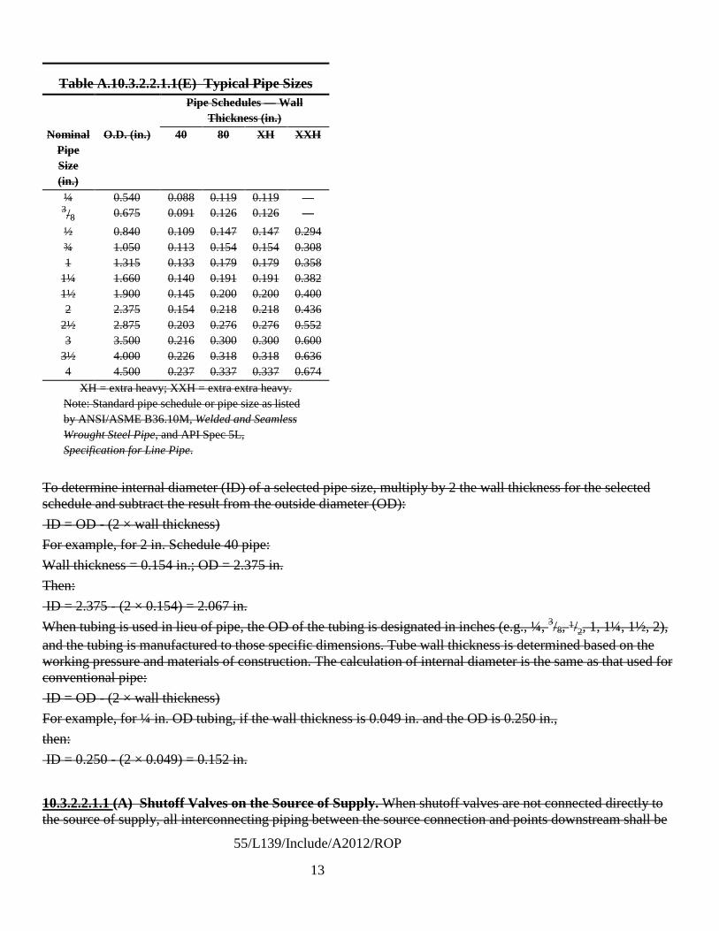
55/L139/Include/A2012/ROP
13
Table A.10.3.2.2.1.1(E) Typical Pipe Sizes Pipe Schedules — Wall
Thickness (in.) Nominal
Pipe Size (in.)
O.D. (in.) 40 80 XH XXH
¼ 0.540 0.088 0.119 0.119 — 3/8 0.675 0.091 0.126 0.126 — ½ 0.840 0.109 0.147 0.147 0.294 ¾ 1.050 0.113 0.154 0.154 0.308 1 1.315 0.133 0.179 0.179 0.358
1¼ 1.660 0.140 0.191 0.191 0.382 1½ 1.900 0.145 0.200 0.200 0.400 2 2.375 0.154 0.218 0.218 0.436
2½ 2.875 0.203 0.276 0.276 0.552 3 3.500 0.216 0.300 0.300 0.600
3½ 4.000 0.226 0.318 0.318 0.636 4 4.500 0.237 0.337 0.337 0.674
XH = extra heavy; XXH = extra extra heavy. Note: Standard pipe schedule or pipe size as listed by ANSI/ASME B36.10M, Welded and Seamless Wrought Steel Pipe, and API Spec 5L, Specification for Line Pipe.
To determine internal diameter (ID) of a selected pipe size, multiply by 2 the wall thickness for the selected schedule and subtract the result from the outside diameter (OD): ID = OD - (2 × wall thickness) For example, for 2 in. Schedule 40 pipe: Wall thickness = 0.154 in.; OD = 2.375 in. Then: ID = 2.375 - (2 × 0.154) = 2.067 in. When tubing is used in lieu of pipe, the OD of the tubing is designated in inches (e.g., ¼, 3/8, 1/2, 1, 1¼, 1½, 2), and the tubing is manufactured to those specific dimensions. Tube wall thickness is determined based on the working pressure and materials of construction. The calculation of internal diameter is the same as that used for conventional pipe: ID = OD - (2 × wall thickness) For example, for ¼ in. OD tubing, if the wall thickness is 0.049 in. and the OD is 0.250 in., then: ID = 0.250 - (2 × 0.049) = 0.152 in.
10.3.2.2.1.1 (A) Shutoff Valves on the Source of Supply. When shutoff valves are not connected directly to the source of supply, all interconnecting piping between the source connection and points downstream shall be

55/L139/Include/A2012/ROP
14
included in the determination of internal diameter for the piping system.
10.3.2.2.1.1(C) The separation distance for piping systems with internal diameters less than those specified in Table 10.3.2.2.1(a) and Table 10.3.2.2.1(b) for the pressure range selected shall be allowed to be reduced with tabular distances determined based on the use of equations in Table 10.3.2.2.1.1(B).
10.3.2.2.2 10.3.2.2.1.1 (D) Separation distances determined based on the use of piping systems with pipe ID greater than that indicated in Table 10.3.2.1(b) 10.3.2.2.1.1(B) shall be subject to review and approval by the AHJ.
A.10.3.2.2.2. The methodology used to determine the distances listed in Table 10.3.2.1(b) has been evaluated for piping up to and including internal diameters of approximately 3 inches (76 mm). The establishment of risk informed separation distances for piping systems with greater internal diameters are subject to a hazard analysis that demonstrates an equivalent level of risk under the provisions of Section 1.5.
10.3.2.3 * 10.3.2.2.1.1(F)* Determination of System Pressure. The system pressure shall be determined by the maximum operating pressure of the storage array with content greater than 400 scf (11.3 m3), irrespective of those portions of the system elevated to a higher pressure.
A.10.3.2.3 A.10.3.2.2.1.1(F) Portions of a system might operate at higher pressures than the bulk supply; however, those portions of the system do not require the use of a pressure rating higher than that of the bulk supply unless there is a storage component exceeding 400 scf (11.3 m3) downstream of the primary storage source and upstream of the source valve. The volume of gas contained within the piping system is not included when the quantity in storage is determined. For example, a 3000 psig (20,684 kPa) storage system that supplies a 6000 psig (41,369 kPa) compressor that directly feeds a process with less than 400 scf (11.3 m3) of intervening storage at a pressure of 6000 psig (41,369 kPa) or less is considered a 3000 psig (20,684 kPa) system.
10.3.2.4* 10.3.2.2.2* Reduction of Distance By Mitigation Means. A.10.3.2.4 A.10.3.2.2.2 Distances to assumed lot lines established for the purpose of determining exterior wall and opening protection should not be confused with lot lines that are property lines in the true sense of the definition, and distances to assumed lot lines can be disregarded in the application of Tables
A permit holder cannot exercise any right of control over the property of others, whether the ownership is public or private. In cases where the permit holder owns an adjacent lot or parcel, the separation from property lines assumes that the permit holder could transfer ownership of the adjacent property at some point, and therefore the requirements for property line separation should be observed.
10.3.2.1.2.1(a) and 10.3.2.1.2.1(b). The lot lines specified in 10.3.2.2.2 are property lines used to separate one lot from another or to separate a property from a street or other public space.
10.3.2.4.1* 10.3.2.2.2 Passive Means. Except for distances to lot lines, operable building openings, air intakes, and overhead utilities, the distances to Group 1 and 2 exposures shown in Tables 10.3.2.1.2.1(a) and 10.3.2.1.2.1(b) shall not apply be permitted to be reduced by one-half and shall not apply to Group 3 exposures where fire barrier walls having a minimum fire resistance rating of 2 hours constructed in accordance with the following are located between the system and the exposure.
(1) Fire barrier walls shall have a minimum fire resistance rating of not less than 2 hours.
(2) The fire barrier wall shall interrupt the line of sight between the bulk hydrogen compressed gas system and the exposure.
(3) The configuration of the fire barrier shall allow natural ventilation to prevent the accumulation of hazardous gas concentrations.
(4) The number of fire barrier walls used to separate individual systems shall be limited to three.

55/L139/Include/A2012/ROP
15
10.3.2.2.4 Where fire barrier walls of three sides are used, the walls shall be in accordance with 11.3.2.2.4.
(5) Fire barrier walls shall be designed and constructed as a structure in accordance with the requirements of the building code without exceeding the specified allowable stresses for the materials of construction utilized. Structures shall be designed to resist the overturning effects caused by lateral forces due to wind, soil, flood and seismic events.
(6)* Table 10.3.2.2.1(a) note f. Where clearance is required between the bulk hydrogen compressed gas system and the barrier wall for the performance of service or maintenance related activities the a minimum horizontal clearance of 5 feet shall be provided between the structure and the system required for access for service-related activities.
(7) The fire barrier wall shall be either an independent structure or the exterior wall of the building adjacent to the storage or use area when the exterior building wall meets the requirements for fire barrier walls.
(8) The minimum wall height shall be not less than 8 ft (2.1 m).
(9) The minimum wall length shall project not less than 5 ft (1.5 m) horizontally beyond the most remote point of the system or the exposure.
A.10.3.2.4.1
As stated by Sandia National Laboratories researchers Houf, Schefer, and Evans in “Analysis of Barriers for Mitigation of Unintended Releases of Hydrogen,” the purpose of the Sandia study was to extend the available database on barrier walls as a hazard mitigation strategy and to provide technical data for risk-informed decisions in hydrogen codes and standards regarding barrier wall design and implementation. Additional research by Sandia’s Jeff LaChance in a paper titled “NFPA Mitigation Analysis” the focus of the research included testing to assess the effectiveness of various barrier designs in terms of the following:
A.10.3.2.2.3 The code has historically recognized that, in certain instances, fire barrier walls can serve as a means to reduce the limits of unacceptable consequences due to the release of hydrogen from high-pressure equipment. Testing other than that related to establish fire resistance of the fire barrier walls has not been documented. Researchers at Sandia National Laboratories have been investigating the use of fire barrier walls as a means of mitigation in the establishment of distances related to the installation of bulk gaseous hydrogen systems, and a technical paper has been presented detailing the early findings.
(1) Deflecting jet flames
(2) Reducing the extent of the flammable cloud resulting from an unignited release
(3) Reducing the magnitude of the radiative heat flux produced by a jet flame from an ignited release
(4) Minimizing the amount of ignition overpressure produced from the barrier confinement
When the work is concluded, it is expected that the results will likely provide the basis for criteria for the proper configuration, design, and construction of such barriers in order that the walls do not create other hazards. The work to date has been limited; however, the results have been promising. Houf, Schefer, and Evans have determined that for the conditions investigated, 2000 psi (13.79 MPa) source pressure and a in. (3.175 mm) diameter round leak, the barrier configurations studied were found to (1) reduce horizontal jet flame impingement hazard by deflecting the jet flame, (2) reduce radiation hazard distances for horizontal jet flames, and (3) reduce horizontal unignited jet flammability hazard distances. For the one-wall vertical barrier and the three-wall barrier configurations examined in the tests, the simulations of the peak overpressure hazard from ignition were found to be approximately 5.8 psi (40 kPa) on the release side of the barrier and approximately 0.73 psi to 0.44 psi (5 kPa to 3 kPa) on the downstream side of the barrier.

55/L139/Include/A2012/ROP
16
As stated by Sandia National Laboratories researchers Houf, Schefer, and Evans in “Evaluation of Barrier Walls for Mitigation of Unintended Releases of Hydrogen,” the purpose of the Sandia study was to extend the available database on barrier walls as a hazard mitigation strategy and to provide technical data for risk-informed decisions in hydrogen codes and standards regarding barrier wall design and implementation. Additional analysis by Sandia (LaChance, Phillips and Houf) in a paper titled “Risk Associated with the Use of Barriers in Hydrogen Refueling Stations” provided insights on the effectiveness of various barrier designs in terms of the following:
(1) Deflecting jet flames
(2) Reducing the extent of the flammable cloud resulting from an unignited release
(3) Reducing the magnitude of the radiative heat flux produced by a jet flame from an ignited release
(4) Minimizing the amount of ignition overpressure produced from the barrier confinement
Houf, Schefer, and Evans have determined that for the conditions investigated, 2000 psi (13.79 MPa) source pressure and a 1/8 in. (3.175 mm) diameter round leak, the barrier configurations studied were found to (1) reduce horizontal jet flame impingement hazard by deflecting the jet flame, (2) reduce radiation hazard distances for horizontal jet flames, and (3) reduce horizontal unignited jet flammability hazard distances. For the one-wall vertical barrier and the three-wall barrier configurations examined in the tests, the simulations of the peak overpressure hazard from ignition were found to be approximately 5.8 psi (40 kPa) on the release side of the barrier and approximately 0.73 psi to 0.44 psi (5 kPa to 3 kPa) on the downstream side of the barrier. Although an overpressure can be expected due to latent ignition of a flammable cloud the overpressure is expected to be limited to a localized area. Special designs for overpressure in addition to the structural loads imposed by the building code have not been required.
The function of the fire barrier wall is to protect the exposure from the system and not the converse. The code assumes that other factors will enter into locating any material or structure in proximity to the bulk hydrogen compressed gas system. For example, if a property or lot line is involved opposite the hydrogen installation the proximity of a building to be constructed on the lot line is regulated by the building code based on the type and occupancy of structure to be constructed.
Investigation is continuing into the parameters for the construction of fire barrier walls. In the interim, a risk-informed approach to the establishment of distance has been introduced into Chapter 10 of this code. The Industrial and Medical Gases Technical Committee recognizes that previous editions of the code have allowed the use of fire barrier walls as a mitigation method. Until such time as the investigation by Sandia National Laboratories or others has been completed, 10.3.2.2.3 provides for the use, in limited cases, of fire barrier walls to mitigate effects on the downstream side of the wall by allowing a reduction of one-half of the separation distance otherwise required through the use of the risk-informed tables.
The resultant distances should be measured from a point on the unexposed (or downstream side) of the fire-barrier wall to the exposure. For example, the 45 ft (14.0 m) distance to lot lines shown for a 3,000 psi gauge (20,684 kPa gauge) system using piping with a maximum internal diameter (ID) of 0.747 in. (18.97 mm) can be reduced to 22.5 ft (7.0 m) between the property line and the fire barrier wall.
The concept of limiting the use of barrier walls is an interim determination that augments the requirements now found in the risk-informed approach to the establishment of separation distances. The outcome of the scientific research underway will measure the effect of the mitigation provided by the walls and will bring a firmness to the fire barrier requirements. The importance of completing the research is that all the factors integral to the construction of fire barrier walls will have been established through the scientific process. The use of the scientific process is a fundamental precept established in the acceptance of the risk-informed approach.
10.3.2.2.3* The distances in (1), (2), (4), and (10) in Table 10.3.2.2.1(a) and Table 10.3.2.2.1(b) shall be

55/L139/Include/A2012/ROP
17
permitted to be reduced by one-half where fire barrier walls having a minimum fire resistance rating of 2 hours are located between the system and the exposure.
10.3.2.4.2* Active Means. Active control systems that mitigate the risk of system leaks and failures can be used as a means to reduce separation distances where approved by the AHJ under the authority granted by Section 1.5.
A.10.3.2.4.2 To determine the acceptability of technologies, processes, products, facilities, materials, and uses attending the design, operation or use of such systems, the AHJ is authorized to require the owner or agent to provide, without charge to the jurisdiction, a technical opinion and report. The model fire prevention codes provide the authority for the AHJ to seek technical assistance from independent third parties with expertise in the matter to be reviewed at the submitter’s expense. The AHJ is authorized to require design submittals to be prepared by, and bear the stamp of, a registered design professional or professional engineer.
Active means of control could include a means to detect leakage or fire coupled with automatic system shut down.
Gas Detection. To utilize gas detection as a means of control the gas sensor would be placed at a point between the bulk hydrogen compressed gas system and the exposure. Gas detection systems may be limited in their ability to detect the presence of hydrogen in the open. The are most effective if the sensor is located within an enclosed space such as an equipment enclosure. If used, gas detection systems should be either listed or approved.
Flame Detection. Flame detection systems may include combination UV/IR detection systems and be installed in accordance with the requirements of NFPA 72.
Ultraviolet flame detectors typically use a vacuum photodiode Geiger–Muller tube to detect the ultraviolet radiation that is produced by a flame. The photodiode allows a burst of current to flow for each ultraviolet photon that hits the active area of the tube. When the number of current bursts per unit time reaches a predetermined level, the detector initiates an alarm.
A single wavelength infrared flame detector uses one of several different photocell types to detect the infrared emissions in a single wavelength band that are produced by a flame. These detectors generally include provisions to minimize alarms from commonly occurring infrared sources such as incandescent lighting or sunlight. An ultraviolet/infrared (UV/IR) flame detector senses ultraviolet radiation with a vacuum photodiode tube and a selected wavelength of infrared radiation with a photocell and uses the combined signal to indicate a fire. These detectors need exposure to both types of radiation before an alarm signal can be initiated. A multiple wavelength infrared (IR/IR) flame detector senses radiation at two or more narrow bands of wavelengths in the infrared spectrum. These detectors electronically compare the emissions between the bands and initiate a signal where the relationship between the two bands indicates a fire. [72, A.5.8.2]
10.3.2.5 Required Separation Distance For All Systems. Separation distances are required for bulk hydrogen compressed gas systems independent of system pressure or internal diameter of piping systems in accordance with the following:
(1) 10.3.2.3 Unloading connections on delivery equipment shall not be positioned closer to any of the exposures cited in 10.3.2.1.2.1(a) or 10.3.2.1.2.1(b) than the distances given for the storage system.
(2) Table 10.3.2.2.1(a) note g Equipment classified as meeting Class I, Division 2, Group B requirements of NFPA 70, National Electrical Code when the area is in accordance with NFPA 497, Recommended Practice for the Classification of Flammable Liquids, Gases, or Vapors and of Hazardous (Classified) Locations for Electrical Installations in Chemical Process Areas.

55/L139/Include/A2012/ROP
18
(3) Table 10.3.2.2.1(a) note h Bulk hydrogen storage systems are allowed to integrate (co-locate) other nonliquefied flammable gas systems where the output of the system is designed to deliver a product in which the gases are mixed or blended for delivery into the user’s system. The minimum separation distance indicated requires a minimum separation between gaseous and liquid systems integrated into a single system where the liquid source is vaporized, compressed, and stored in the gaseous state shall be 15 feet.
(4) 10.3.1.2 Systems within 50 ft (15 m) of aboveground storage of all classes of flammable and combustible liquids shall be located on ground higher than such storage, except where dikes, diversion curbs, grading, or separating solid walls are used to prevent accumulation of these liquids under the system.
10.3.2.6 Hydrogen And Other Flammable Gas Blends. Bulk hydrogen compressed gas storage systems are allowed to integrate (co-locate) other nonliquefied flammable gas systems as a component of the hydrogen gas system without separation where the output of the system is designed to deliver a product in which the gases are mixed or blended for delivery into the user’s system.
10.4 Design Requirements at Specific Locations. 10.4.1 Outdoor Locations. 10.4.1.1 Where overhead cover is provided, it shall be in accordance with the provisions of 6.5.2. 10.4.1.2 Electrical wiring and equipment shall be in accordance with Table 10.4.1.2.
Table 10.4.1.2 Electrical Area Classification Location Classification Extent of Classified Area Storage equipment excluding the piping system downstream of the source valve
Class I, Division 2 Between 0 ft (0 m) and 15 ft (4.6 m)
10.4.1.3 Vehicular protection shall be provided in accordance with 7.1.8.3. 10.4 Underground Bulk Hydrogen Compressed Gas Systems 10.4.1 10.4.2 Underground Systems. Bulk hydrogen compressed gas systems Gaseous hydrogen systems installed underground where compressed gas containers are to be buried in contact with earth or fill shall be in accordance with 10.4.2. 10.4.1.1 10.4.2.1 Design. Pressure compressed gas containers installed underground using burial methods shall be of seamless construction in accordance with Part UF or Appendix 22 of the ASME Boiler and Pressure Vessel Code, Section VIII, Division 1. 10.4.1.1.1 10.4.2.1.1* Compressed gas containers shall be designed to include cyclic pressure life calculations using fracture mechanics methods. 10.4.1.1.2 10.4.2.1.2 Compressed Gas Container Examination. 10.4.1.1.2.1 10.4.2.1.2.1 Compressed gas containers shall be examined for internal and external surface flaws and inclusions before burial or at the time of manufacture. 10.4.1.1.2.2 10.4.2.1.2.2 Compressed gas containers with flaws or inclusions exceeding the lesser of 5 percent of the wall thickness or 0.12 in. (3 mm) shall not be used.

55/L139/Include/A2012/ROP
19
10.4.1.2 10.4.2.1.3 Composite Containers. (Reserved) 10.4.1.3 10.4.2.2 Corrosion Protection. Compressed gas containers and underground piping shall be protected from corrosion in accordance with 7.1.10.9 or 7.1.17 as applicable. 10.4.1.4 10.4.2.3* Outlet Connections. 10.4.1.4.1 10.4.2.3.1 Threaded compressed gas container outlet connections shall be designed with primary and secondary seals that shall be tested for functionality. 10.4.1.4.2 10.4.2.3.2 The seal design shall include a method of detecting a leak in the primary seal. 10.4.1.5 10.4.2.4 Piping Systems. 10.4.1.5.1 10.4.2.4.1 Joints in the piping system shall be butt welded and 100 percent inspected using nondestructive testing (NDT) methods in accordance with the requirements of ANSI/ASME B31.3, Process Piping, or other approved standards. 10.4.1.5.2 10.4.2.4.2 Valves, controls, safety devices, and instrumentation shall be above ground and accessible to authorized personnel. 10.4.1.6 10.4.2.5 Location. Compressed gas containers shall be located in accordance with 10.4.2.5.1 through 10.4.2.5.4. 10.4.1.6.1 10.4.2.5.1 Underground compressed gas containers shall not be located beneath buildings. 10.4.1.6.2 10.4.2.5.2 Compressed gas containers and associated equipment shall be located with respect to foundations and supports of other structures such that the loads carried by such structures cannot be transmitted to the tank. 10.4.2.5.3 Compressed Gas Container Separation Distances. 10.4.1.6.3 10.4.2.5.3.1 The distance from any part of the compressed gas container to the nearest wall of a basement, pit, cellar, or lot line shall not be less than 10 ft (3.1 m). 10.4.1.6.4 10.4.2.5.3.2 A structure or foundation of a structure on the same property shall not be erected or constructed within 10 ft (3.1 m) of any point on the container surface, unless the footings extend to the bottom of the container or the container’s foundation. 10.4.1.6.5 10.4.2.5.4 A minimum distance of 1 ft (0.3 m), shell to shell, shall be maintained between adjacent underground containers. 10.4.1.6.6 10.4.2.5.5* A minimum distance of 3 ft (0.9 m) shall be maintained between compressed gas containers and buried utilities. 10.4.1.7 10.4.2.6 Foundations. Underground compressed gas containers shall be set on foundations constructed in accordance with the building code, and surrounded with not less than 6 in. (152 mm) of noncorrosive inert material. 10.4.1.7.1 10.4.2.7.2 The concrete shall extend a minimum of 1 ft (0.3 m) horizontally beyond the footprint of the tank in all directions. 10.4.1.8 10.4.2.7 Depth, Cover, and Fill. 10.4.2.7.1 Containers shall be buried such that the top of the container is covered with a minimum of 1 ft (0.3 m) of earth and with concrete a minimum of 4 in. (101 mm) thick placed over the earthen cover. 10.4.1.9 10.4.2.8* Anchorage and Security. Compressed gas containers installed underground in flood hazard areas shall be anchored to prevent flotation, collapse, or lateral movement resulting from hydrostatic loads, including the effects of buoyancy, during conditions of the design flood. 10.4.1.10 10.4.2.9 Venting of Underground Compressed Gas Containers. Vent pipes for underground compressed gas containers shall be in accordance with 10.2.1. 10.4.1.11 10.4.2.10 Overfill Protection and Prevention Systems. An approved means or method shall be

55/L139/Include/A2012/ROP
20
provided to prevent the overfilling of the storage containers. 10.4.1.1210.4.2.11 Physical Protection. Piping and control equipment ancillary to underground containers that is located above ground shall be protected from physical damage in accordance with 7.1.8.3. 10.5 10.4.3 Installation in Vaults Above and Below Ground. (Reserved) 10.6 Indoor Bulk Hydrogen Compressed Gas Systems 10.6.1 General. 10.6.1.1 10.3.2.1 The location of bulk hydrogen compressed gas systems shall be in accordance with Table 10.6.1.1 10.3.2.1.
Table 10.6.1.1 10.3.2.1 Location of Bulk Gaseous Hydrogen Compressed Gas Systems Quantity of Hydrogen
Location ≤MAQ >MAQ to <3500
scf (<99 m3)
≥3500 5000 scf to <15,000 scf (≥14299
m3 to <425 m3) ≥15,000 scf (≥425 m3) Outdoors A A A A In a detached building A A A A In a gas room, in accordance with Section 6.4
A A A Detached building required
Not in a gas room A NA NA NA A: Allowed. NA: Not allowed.
10.4.6 Indoor Hydrogen System Location. 10.4.6.1 Hydrogen systems of less than 3500 scf (99 m3) and greater than the MAQ, where located inside buildings, shall be located in the building so that the system will be as follows:
(1) In a ventilated area in accordance with the provisions of Section 6.15 (2) Separated from incompatible materials in accordance with the provisions of 7.1.10.2 (3) A distance of 25 ft (7.6 m) from open flames and other sources of ignition (4) A distance of 50 ft (15 m) from intakes of ventilation, air-conditioning equipment, and air compressors
(a) The distance shall be permitted to be reduced to 10 ft (3.1 m) where the room or area is protected by a listed detection system per Article 500.7(K) of NFPA 70, National Electrical Code, and the detection system shuts down the fuel supply in the event of a leak that results in a concentration that exceeds 25 percent of the LFL.
(b) Isolation valves used to isolate the fuel supply shall be of a fail-safe design. (5) A distance of 50 ft (15 m) from other flammable gas storage (6) Protected against damage in accordance with the provisions of 7.1.8.3
10.4.6.2 Systems Installed in One Room. 10.4.6.2.1 More than one system of 3500 scf (99 m3) or less shall be permitted to be installed in the same room or area, provided the systems are separated by at least 50 ft (15 m) or a full-height fire-resistive partition having a minimum fire resistance rating of 2 hours is located between the systems. 10.4.6.2.2 The separation distance between multiple systems of 3500 scf (99 m3) or less shall be permitted to

55/L139/Include/A2012/ROP
21
be reduced to 25 ft (7.6 m) in buildings where the space between storage areas is free of combustible materials and protected with a sprinkler system designed for Extra Hazard, Group 1 in accordance with the requirements of Section 6.9.
10.6.1.2 10.6* Fire Protection. Fire protection shall be in accordance with the requirements of Section 6.9. 10.6.2 10.4.4 Detached Buildings. 10.6.2.1 10.4.4.1 Detached buildings shall be constructed of noncombustible or limited-combustible materials in accordance with the requirements of Section 6.5. 10.6.2.2 10.4.4.2 Ventilation shall be provided in accordance with the requirements of Section 6.15. 10.6.2.2.1 10.4.4.2.1 Outlet openings shall be located at the high point of the room in exterior walls or the roof. 10.6.2.2.2 10.4.4.2.2 Inlet and outlet openings shall each have a minimum total area of 1 ft2/1000 ft3 (1 m2/305 m3) of room volume. 10.6.2.2.3 10.4.4.2.3 Discharge from outlet openings shall be directed or conducted to the atmosphere. 10.6.2.3 10.4.4.3* Explosion control shall be provided in accordance with the requirements of Section 6.8. 10.6.2.4 10.4.4.4 Electrical equipment shall be in accordance with Article 501 of NFPA 70, National Electrical Code, for Class I, Division 2 locations. 10.6.2.5 10.4.4.5 Heating, if provided, shall be by steam, hot water, or other indirect means except that electrical heating shall be permitted to be used if in compliance with 10.4.4.4. 10.6.3 10.4.5 Hydrogen Gas Rooms. 10.6.3.1 10.4.5.1 Floors, walls, and ceilings shall be constructed of noncombustible or limited-combustible materials in accordance with the requirements of the building code. 10.6.3.1.1 10.4.5.1.1 Interior walls or partitions shall have a fire resistance rating of not less than 2 hours, shall be continuous from floor to ceiling, and shall be anchored to resist movement. 10.6.3.1.2 10.4.5.1.2 Not less than 25 percent of the perimeter wall shall be an exterior wall. 10.6.3.1.3 10.4.5.1.3 Openings to other parts of the building shall not be permitted. 10.6.3.1.4 10.4.5.1.4 Windows and doors shall be in exterior walls only. 10.6.3 2 10.4.5.2 Ventilation shall be as provided in Section 6.15. 10.6.3.3 10.4.5.3 Explosion control shall be provided in accordance with the requirements of Section 6.8. 10.6.3.4 10.4.5.4 There shall be no sources of ignition from open flames, electrical equipment, or heating equipment. 10.6.3.5 10.4.5.5 Electrical equipment shall be in accordance with Article 501 of NFPA 70, National Electrical Code, for Class I, Division 2 locations. 10.6.3.6 10.4.5.6 Heating, if provided, shall be by steam, hot water, or indirect means except that electrical heating shall be permitted to be used if in compliance with 10.6.3.6 10.4.5.5. Also, in support of A.10.3.2.4.1 add the following informational references to Annex H under Section H.2.2.
LaChance, J., Phillips, J., Houf, W., “Risk Associated with the Use of Barriers in Hydrogen Refueling Stations,” National Hydrogen Association Conference & Expo, Long Beach, California, May 3-6, 2010 W. Houf, R. Schefer, G. Evans, E. Merilo, and M. Groethe, “Evaluation Of Barrier Walls For Mitigation Of Unintended Releases Of Hydrogen,” International Journal of Hydrogen Energy, Vol. 35, Issue 10, May 2010,

55/L139/Include/A2012/ROP
22
pp. 4758-4775.

55/L139/Include/A2012/ROP
23
REASONS:
A joint task group, known as Task Group 6, has been appointed by the Chairs of the NFPA 2, Hydrogen Technologies Code and the IMG TC. Revisions to separation distance tables in NFPA 55 were the focus of this group in the last code revision cycle. Feedback from industry and code users alike sought a simplification of requirements relative to the application of the tabular distances and the work of the task group continued.
One of the major stumbling blocks for readers of the existing tables was one where an assumption was made that distances should increase as system pressure increased. The use of pressure to pipe ID changes as pressure increases resulting in a decrease in the pipe ID and the corresponding leak rate which is generally based on 3% of the internal area of the largest section of pipe in the system under the pressure indicated.
Other complaints heard were that the table was too complex with too many pieces of data. Others found the use of complex exponential equations difficult when pipe IDs other than those common IDs listed in the table were encountered. Other comments were received that the metric units of measure were inconsistent and questions arose as to why there were two tables. To make things a bit more confusing a printing error resulted in quantity being placed into the table heading (corrected by Errata #1).
The task group addressed these issues with several changes in the manner in which the data is presented without changing either the criteria used or the end results.
• The table was simplified by grouping the exposures into three separate groups with Groups 1 and 2 being people sensitive groups and Group 3 being of a material or property nature.
• Table 10.3.2.1(a) has maintained the four common pressure ranges and it has been combined with Table 10.3.2.2.1(b) so that SI units are provided in the same table.
• Distances have been calculated first in inch-pound units of measure and rounded to the nearest foot (instead of five feet), and SI units have been determined using standard conversion formulas and rounding to the nearest meter using conventional rounding.
• The footnotes to Table 10.3.2.2.1 have been removed and placed into an annex note as they were informative.
• The pipe ID has been listed for the Typical Maximum Pipe Size (Table 10.3.2.1(a)).
• Table 10.3.2.1(b) is new. It replaces Table A.10.3.2.2.1.1(E) and the use of exponential formulas shown in A.10.3.2.2.1.1(B) in the 2010 Edition.
• Table 10.3.2.2.1(b) lists the pipe diameters in a range generally from 0.2 to 2 inches in increments of 1/10th of an inch. The resultant separation distance for each exposure group has been calculated and displayed in the table. The formulas have been simplified and are shown at the top of each column for each exposure group. For example, for Group 1 exposures in the 15 to 250 psig pressure range distance “D” is determined by multiplying the internal pipe ID in mm by 0.231 and rounding to the nearest foot or corresponding nearest meter. Interpolation between values can be used as indicated in table footnotes. The table is functional for pipe or tube as all values are based on ID.
• The exposures in each group are those established in Table 10.3.2.1(a).
• Comments received regarding an expected progression of distance with increasing pressures remain unresolved for Table 10.3.2.1(a). By referring to Table 10.3.2.1(b) it becomes clear that

55/L139/Include/A2012/ROP
24
this is the case as the distances are normalized across any single row based on a single pipe ID. For example for a 0.7 inch ID pipe the distances across the pressure ranges in the table range as follows:
>15 to ≤250 psi – 4 ft
>250 to ≤3000 psi – 13 ft
>3000 to ≤7500 psi – 20 ft
>7500 to ≤15000 psi – 26 ft
• Table 10.3.2.1(a) displays the “typical” sizes based on pressure. On the other hand Table 10.3.2.2(b) allows a rapid assessment of pipe sizes in the field without the use of what might be viewed as cumbersome calculations. Once an ID is determined the distances are easily estimated and verified.
As work on Section 10.3 was conducted it became apparent that the organization of Chapter 10 could be improved. For example, Section 10.4 established requirements for outdoor locations when weather protection was used. Electrical classification for wiring was specified. The requirements of Chapter 6 appearing in 10.4 appeared to be redundant to the requirements of Chapter 6 triggered by 10.1. Having a general requirement for electrical buried in a section following the tables appeared to be out of order. The chapter was reorganized to follow a general outline that established the following major sections:
10.1 Applicability
10.2 General Requirements applicable to all bulk GH2 systems
10.3 Outdoor
10.3.1 Outdoor General Requirements
10.3.2 Specific requirements for outdoor systems
10.4 Underground Systems
10.5 Vaults above or below ground (remains reserved)
10.6 Indoor
10.6.1 Indoor General Requirements
10.6.2 Detached Buildings
10.6.3 Hydrogen Gas Rooms
Modifications have been made to correlate the use of the term “bulk hydrogen compressed gas system” throughout Chapter 10. The substantive modifications other than reformatting of the chapter are found in Section 10.3. Using the table below the user can follow the reorganization and the table becomes a road map to how the Chapter was reconstructed.
Old Section No. New Section No. Reason for change

55/L139/Include/A2012/ROP
25
Old Section No. New Section No. Reason for change
10.1 10.1 Clarification. Chapter 9 applies to bulk oxygen systems.
10.1.1 10.1.1 Modifies definition of bulk hydrogen compressed gas system. Separate proposal issued and correlated.
10.1.2 - Section deleted. Bulk systems are regulated as individual systems under the requirements of Chapter 10.
10.2 10.2 Existing Section 10.2 was titled design of gaseous hydrogen systems. The general requirements for all bulk GH2 systems have been moved to Section 10.2.
10.2.1 10.2.2 Relocated to 10.2.2. New Section 10.2.1 is now marking which was relocated from 10.2.5.
10.2.2 Relocated to 10.2.3 with minor edits.
10.2.2.1 Relocated to 10.2.3.1.
10.2.2.2 Relocated to 10.2.3.1.1
10.2.3 Section heading only. Deleted.
10.2.3.1 Relocated to 10.2.1.2
10.2.3.2 Relocated to 10.2.1.3
10.2.4 10.2.4
10.2.4.1 10.2.4.1 Minor edits
10.2.4.1.1 10.2.4.1.1 Minor edits
10.2.4.2 10.2.4.2 Minor edits
10.2.4.3 10.2.4.3 Minor edits
10.2.4.4 Relocated to 10.2.5.1
10.2.5 Relocated to 10.2.1
10.2.5.1 Relocated to 10.2.1.1
10.2.5.2 Relocated to 10.2.1.2
10.2.6 Relocated to 10.2.5
10.3 10.3 Title only. Minor edits.
10.3.1 10.3.1 The statement in 10.3.1.1 has been moved to 10.3.1 and terminology has been coordinated with the published definition for bulk hydrogen compressed gas system found in Chapter 3.
10.3.1.1 10.3.1 Relocated 10.3.1.1 to 10.3.1 with Editorial change.
10.3.1.2 10.3.2.5 (4) The text has been moved without change to 10.3.2.5 item (4).
10.3.2 10.3.2 The existing heading has been deleted. The title to Section 10.3.2.2 has been revised and the section renumbered to 10.3.2.
10.3.2.1 10.6.1.1 Modified and relocated to 10.6.1.1 and applied to indoor situations only.
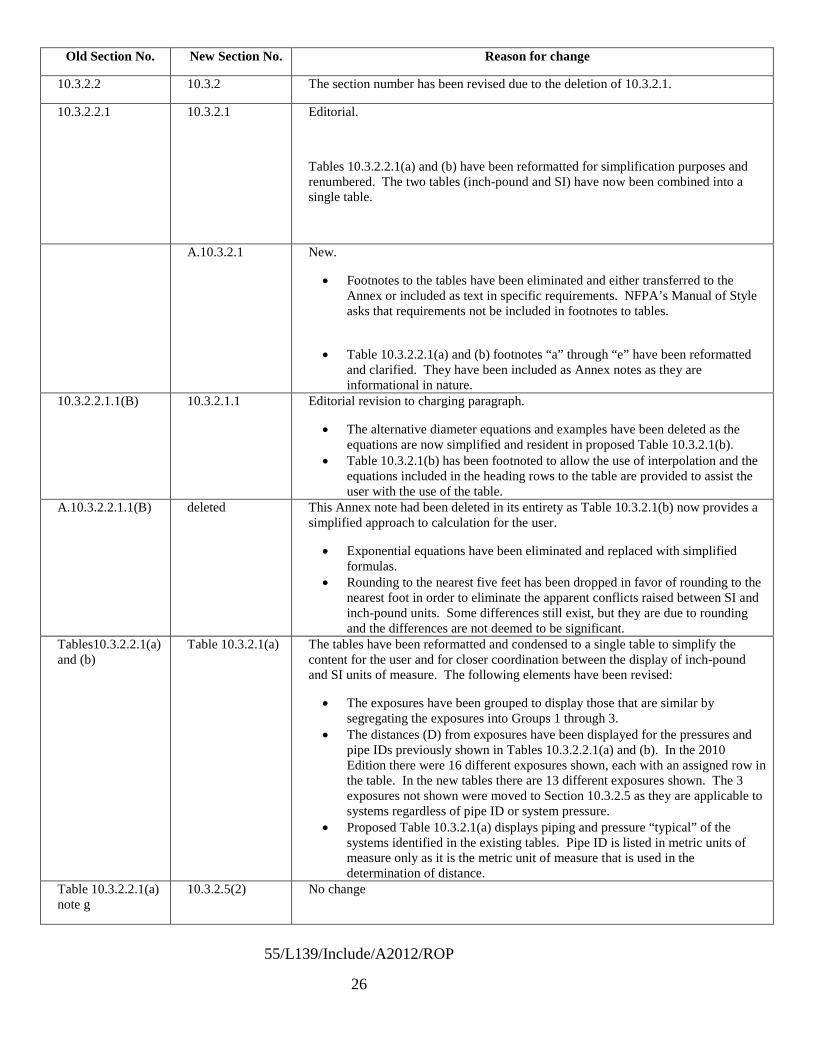
55/L139/Include/A2012/ROP
26
Old Section No. New Section No. Reason for change
10.3.2.2 10.3.2 The section number has been revised due to the deletion of 10.3.2.1.
10.3.2.2.1 10.3.2.1 Editorial.
Tables 10.3.2.2.1(a) and (b) have been reformatted for simplification purposes and renumbered. The two tables (inch-pound and SI) have now been combined into a single table.
A.10.3.2.1 New.
• Footnotes to the tables have been eliminated and either transferred to the Annex or included as text in specific requirements. NFPA’s Manual of Style asks that requirements not be included in footnotes to tables.
• Table 10.3.2.2.1(a) and (b) footnotes “a” through “e” have been reformatted and clarified. They have been included as Annex notes as they are informational in nature.
10.3.2.2.1.1(B) 10.3.2.1.1 Editorial revision to charging paragraph.
• The alternative diameter equations and examples have been deleted as the equations are now simplified and resident in proposed Table 10.3.2.1(b).
• Table 10.3.2.1(b) has been footnoted to allow the use of interpolation and the equations included in the heading rows to the table are provided to assist the user with the use of the table.
A.10.3.2.2.1.1(B) deleted This Annex note had been deleted in its entirety as Table 10.3.2.1(b) now provides a simplified approach to calculation for the user.
• Exponential equations have been eliminated and replaced with simplified formulas.
• Rounding to the nearest five feet has been dropped in favor of rounding to the nearest foot in order to eliminate the apparent conflicts raised between SI and inch-pound units. Some differences still exist, but they are due to rounding and the differences are not deemed to be significant.
Tables10.3.2.2.1(a) and (b)
Table 10.3.2.1(a) The tables have been reformatted and condensed to a single table to simplify the content for the user and for closer coordination between the display of inch-pound and SI units of measure. The following elements have been revised:
• The exposures have been grouped to display those that are similar by segregating the exposures into Groups 1 through 3.
• The distances (D) from exposures have been displayed for the pressures and pipe IDs previously shown in Tables 10.3.2.2.1(a) and (b). In the 2010 Edition there were 16 different exposures shown, each with an assigned row in the table. In the new tables there are 13 different exposures shown. The 3 exposures not shown were moved to Section 10.3.2.5 as they are applicable to systems regardless of pipe ID or system pressure.
• Proposed Table 10.3.2.1(a) displays piping and pressure “typical” of the systems identified in the existing tables. Pipe ID is listed in metric units of measure only as it is the metric unit of measure that is used in the determination of distance.
Table 10.3.2.2.1(a) note g
10.3.2.5(2) No change

55/L139/Include/A2012/ROP
27
Old Section No. New Section No. Reason for change
Table 10.3.2.2.1(a) note h first sentence.
10.3.2.6 Editorial
Table 10.3.2.2.1(a) note h second sentence
10.3.2.5(3) Editorial changes to note “h” as found in 10.3.2.5(3). Extract of second sentence of note “h” only.
Table 10.3.2.1(b) A new table has been added to include information previously found in A.10.3.2.2.1.1 (B) and Table A.10.3.2.2.1.1 (E).
• The table is arranged by required distance (D) related to pipe ID displayed in 1/10th inch increments along with a metric value of pipe ID shown as (d).
• Distances are displayed in the table by Exposure Group for each of the four pressures shown in table 10.3.2.1(a). Both SI and inch-pound units of measure are displayed.
• The value of “d” is used in the equations represented in the formula row, i.e., D = 0.231d, and used to calculate distance D as shown in the table. For example, to calculate distance D for a pipe ID of 5.1 mm for Group 1 exposures the user multiplies 5.1 by 0.231 and the value is displayed to the nearest meter. The metric distance D is then converted to SI units of measure by multiplying the unrounded metric result by the conversion factor 3.281 and rounding the inch-pound unit to the nearest foot.
• The complex formulas shown in 55:A.10.3.2.2.1.1(b) have been eliminated. 10.3.2.2.1.1 10.3.2.2 Editorial
10.3.2.2.1.1(A) deleted The section has been deleted as no requirements were established that were different from those already imposed by 10.3.2.2.1.
10.3.2.2.1.1(C) deleted The provision is not needed in light of the creation of Table 10.3.2.1(b) and the charging language provided in 10.3.2.1.
10.3.2.2.1.1(D) 10.3.2.2.2 Editorial
A.10.3.2.2.2 Annex note based on bounding data produced by Sandia National Laboratories study. Sandia ran computer code calculations for leak diameters up to 13.5 mm and then did the curve-fits to this data up to and including a nominal 3 inch (76.2 mm) pipe ID. A 3% leak is based on 3% of the internal pipe flow area.
A = pi * d2/4
Dpipe = Dleak/(0.1732) This means that the I.D. of the of pipe for this 13.5 mm diameter leak would be 13.5/0.1732 = 77.94 mm A 9 mm diameter leak would correspond to a pipe ID of 51.96 mm for a 3% of flow area leak.
10.3.2.2.1.1(E) 10.3.2.2.1 Editorial
A.10.3.2.2.1.1(E) A.10.3.2.2.1 The introduction of Table 10.3.2.1(b) addresses the principles embodied in existing A.10.3.2.2.1.1(e) as shown in the table of typical pipe sizes and examples showing the calculation of pipe ID. Table 10.3.2.1(b) goes beyond just steel pipe and includes piping and tubing of any construction as it is simply a generic table based on pipe ID without regard to the type of pipe or tube involved. As a result the code is broadened
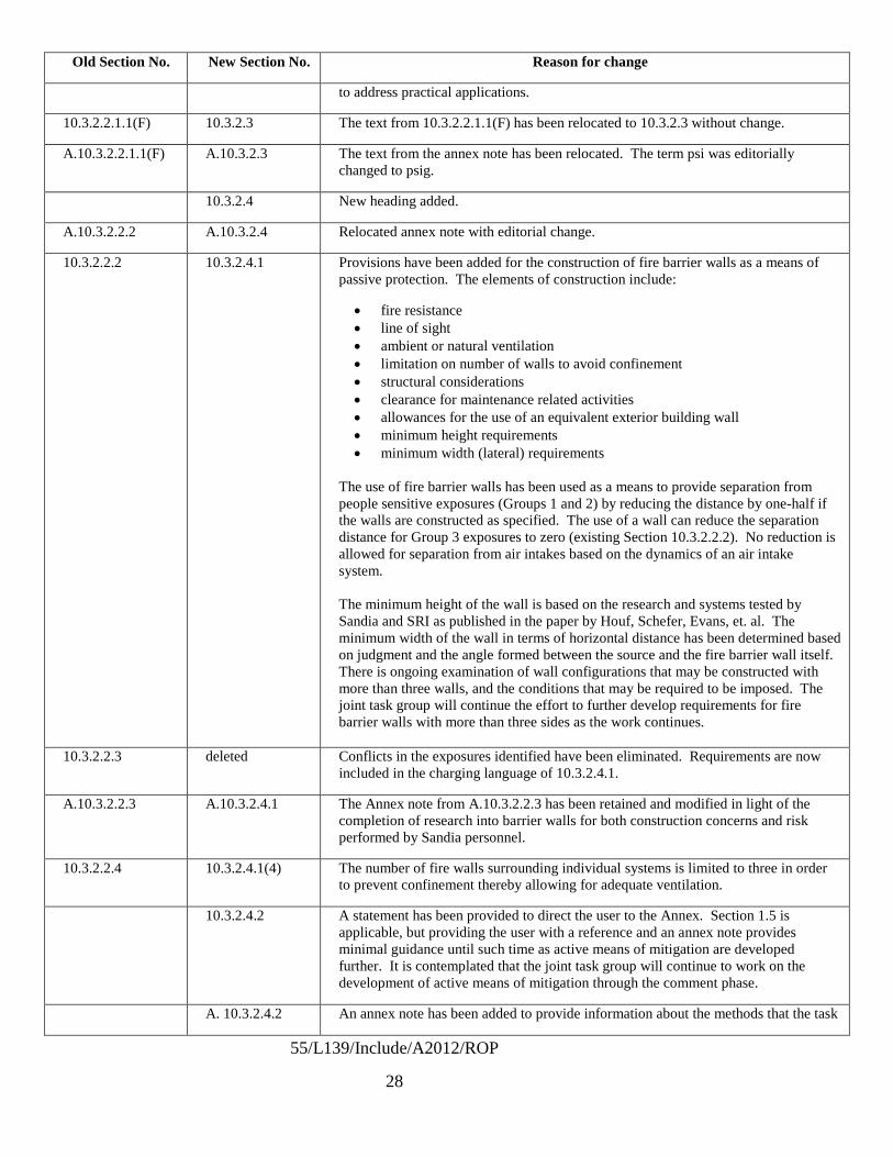
55/L139/Include/A2012/ROP
28
Old Section No. New Section No. Reason for change
to address practical applications.
10.3.2.2.1.1(F) 10.3.2.3 The text from 10.3.2.2.1.1(F) has been relocated to 10.3.2.3 without change.
A.10.3.2.2.1.1(F) A.10.3.2.3 The text from the annex note has been relocated. The term psi was editorially changed to psig.
10.3.2.4 New heading added.
A.10.3.2.2.2 A.10.3.2.4 Relocated annex note with editorial change.
10.3.2.2.2 10.3.2.4.1 Provisions have been added for the construction of fire barrier walls as a means of passive protection. The elements of construction include:
• fire resistance • line of sight • ambient or natural ventilation • limitation on number of walls to avoid confinement • structural considerations • clearance for maintenance related activities • allowances for the use of an equivalent exterior building wall • minimum height requirements • minimum width (lateral) requirements
The use of fire barrier walls has been used as a means to provide separation from people sensitive exposures (Groups 1 and 2) by reducing the distance by one-half if the walls are constructed as specified. The use of a wall can reduce the separation distance for Group 3 exposures to zero (existing Section 10.3.2.2.2). No reduction is allowed for separation from air intakes based on the dynamics of an air intake system. The minimum height of the wall is based on the research and systems tested by Sandia and SRI as published in the paper by Houf, Schefer, Evans, et. al. The minimum width of the wall in terms of horizontal distance has been determined based on judgment and the angle formed between the source and the fire barrier wall itself. There is ongoing examination of wall configurations that may be constructed with more than three walls, and the conditions that may be required to be imposed. The joint task group will continue the effort to further develop requirements for fire barrier walls with more than three sides as the work continues.
10.3.2.2.3 deleted Conflicts in the exposures identified have been eliminated. Requirements are now included in the charging language of 10.3.2.4.1.
A.10.3.2.2.3 A.10.3.2.4.1 The Annex note from A.10.3.2.2.3 has been retained and modified in light of the completion of research into barrier walls for both construction concerns and risk performed by Sandia personnel.
10.3.2.2.4 10.3.2.4.1(4) The number of fire walls surrounding individual systems is limited to three in order to prevent confinement thereby allowing for adequate ventilation.
10.3.2.4.2 A statement has been provided to direct the user to the Annex. Section 1.5 is applicable, but providing the user with a reference and an annex note provides minimal guidance until such time as active means of mitigation are developed further. It is contemplated that the joint task group will continue to work on the development of active means of mitigation through the comment phase.
A. 10.3.2.4.2 An annex note has been added to provide information about the methods that the task

55/L139/Include/A2012/ROP
29
Old Section No. New Section No. Reason for change
group has considered for means of active mitigation. The code user can always use Section 1.5 as a means to introduce alternative methods of achieving compliance. In this instance gas detection and flame detection have been discussed as the means, however, prescriptive requirements are yet to be developed. Providing minimal guidance to the code user, designer and code official demonstrates conditions that must be considered when addressing equivalency to otherwise required separation distance.
10.3.2.5 New. Distance limitations for exposures that are independent of pressure and/or pipe ID have been located in this new section.
10.3.2.3 10.3.2.5(1) Text relocated from 10.3.2.3 with editorial change.
Table 10.3.2.2.1(a) note g
10.3.2.5(2) Text relocated from Table 10.3.2.2.1(a) and (b) without change.
Table 10.3.2.2.1(a) note h second sentence
10.3.2.5(3) Text relocated from Table 10.3.2.2.1(a) and (b) with editorial change intended to further subdivide the requirement into two paragraphs and to include the tabular distance (of 15 feet) previously included in the Tables as a requirement.
10.3.1.2 10.3.2.5(4) Relocation of requirements from 10.3.1.2 without change.
Table 10.3.2.2.1(a) note h first sentence.
10.3.2.6 Relocation of first sentence of a footnote to Tables 10.3.2.2.1(a) and (b) with editorial changes to establish an independent section for requirements related to co-locating hydrogen with other non-liquefied compressed gases to be used for the purpose of creating hydrogen/flammable gas blends.
10.4 Deleted – title only
10.4.1 Deleted - title only.
10.4.1.1 Deleted, compliance with Chapter 6 is required by 10.1.
10.4.1.2 Relocated to 10.3.1.3
Table 10.4.1.2 Relocated to Table 10.3.1.3
10.4.1.3 Relocated to 10.2.8.1
10.4.2 through 10.4.2.11
Relocated to 10.4.1 through 10.4.1.12
10.4.3 Relocated to 10.5
10.4.4 through 10.4.4.5
Relocated to10.6.2 through 10.2.6.5
10.4.5 through 10.4.5.6
Relocated to 10.6.3 through 10.6.3.6
10.4.6 Deleted and proposed (separate proposal) to be relocated to a new Section 7.6.3.
10.4.6.1 Deleted and proposed (separate proposal) to be relocated to a new Section 7.6.3.
10.4.6.2 Deleted and proposed (separate proposal) to be relocated to a new Section 7.6.3.
10.4.6.2.1 Deleted and proposed (separate proposal) to be relocated to a new Section 7.6.3.
10.4.6.2.2 Deleted and proposed (separate proposal) to be relocated to a new Section 7.6.3.

55/L139/Include/A2012/ROP
30
Old Section No. New Section No. Reason for change
10.5 Relocated to 10.2.7
10.5.1 Relocated to 10.2.2.1
10.5.2 Relocated to 10.2.7.1
10.5.2.1 Relocated to 10.2.7.1.1
10.5.2.2 Relocated to 10.2.7.1.2
10.5.3 Relocated to 10.2.7.2
10.5.4 Deleted. Compliance with Chapter 7 is required by 10.1. Table 10.3.2.2.1(a) and (b) are specific. Section 7.1 is general. Specific requirements override general requirements in any code application.
10.6 Relocated to 10.6.1.2 as a general requirement for indoor applications
10.7 through 10.7.8 Relocated to 10.2.8 through 10.2.8.9
10.8 through 10.8.4.6
Relocated to 10.2.6 through 10.2.6.8

Report on Proposals – June 2012 NFPA 55an ID is determined the distances are easily estimated and verified.As work on Section 10.3 was conducted it became apparent that the organization of Chapter 10 could be improved. Forexample, Section 10.4 established requirements for outdoor locations when weather protection was used. Electricalclassification for wiring was specified. The requirements of Chapter 6 appearing in 10.4 appeared to be redundant tothe requirements of Chapter 6 triggered by 10.1. Having a general requirement for electrical buried in a sectionfollowing the tables appeared to be out of order. The chapter was reorganized to follow a general outline thatestablished the following major sections:
10.1 Applicability10.2 General Requirements applicable to all bulk GH2 systems10.3 Outdoor10.3.1 Outdoor General Requirements10.3.2 Specific requirements for outdoor systems10.4 Underground Systems10.5 Vaults above or below ground (remains reserved)10.6 Indoor10.6.1 Indoor General Requirements10.6.2 Detached Buildings10.6.3 Hydrogen Gas RoomsModifications have been made to correlate the use of the term “bulk hydrogen compressed gas system” throughoutChapter 10. The substantive modifications other than reformatting of the chapter are found in Section 10.3. Using thetable below the user can follow the reorganization and the table becomes a road map to how the Chapter wasreconstructed.
(See attached)
53Printed on 1/6/2011

Report on Proposals – June 2012 NFPA 55_______________________________________________________________________________________________55- Log #43
_______________________________________________________________________________________________Robert Wichert, FCHEA, and Chris Radley, Altergy
Revise text to read as follows:10.1.1 This chapter shall not apply to individual systems using containers having a total hydrogen content of less than
400 scf (11 m3) if each system is separated by a distance not less than 5 ft (1.5 m).10.1.2 Where individual systems, each having a total hydrogen content of less than 400 scf (11 m3), are located less
than 5 ft (1.5 m) from each other, this code shall apply.10.1.1 Indoor Systems10.1.1.1 This chapter shall not apply to individual indoor systems using containers having a total hydrogen content of
less than the MAQ defined by Table 6.3.1.1 for the particular application.10.1.1.2 Indoor systems using containers having a total hydrogen content of more than the MAQ defined by Table
6.3.1.1 for the particular application shall comply with this chapter.10.1.2 Outdoor Systems10.1.2.2 Outdoor systems up to 3,000 cubic feet (83 m3) are not subject to this chapter.10.1.2.3 Outdoor systems over 3,000 cubic feet (83 m3) but less than 12,000 cubic feet (332 m3) shall comply with
sub-clause 7.3.2 of NFPA 2 and its subordinate and referenced sub-cluases.10.1.3 Where individual hydrogen systems are located within 5 feet of each other, they shall be treated as a single
system.The current bulk hydrogen definition of 400 scf is equivalent to 1.02 kg. The energy content of 1 kg of
hydrogen is roughly the same as 1 gal of gasoline. Therefore, the current bulk threshold energy content is currentlybeing set equivalent to 1 gal of gasoline. This does not seem reasonable.The bulk threshold for liquefied hydrogen systems is 39.7 gallons which is much greater than 400 scf of gaseous
hydrogen.The indoor MAQ for hydrogen according to Table 6.3.1.1 is 1,000 cubic feet for unsprinklered areas without a gas
cabinet or gas room or enclosure Up to 4000 scf is allowed for indoor sprinklered systems in a gas cabinet, gas room,or enclosure.The outdoor MAQ for hydrogen gas is 3,000 cubic feet in accordance with the International Fire Code, IFC: 2006 Table
2703.1.1 (3).There is no reason to invoke additional requirements for amounts below the MAQ in either case.Additional requirements for outdoor systems using or storing more 3,000 cubic feet, but less than 12,000 cubic feet, of
hydrogen are suggested using sub-clause 7.3.2 of NFPA 2 (non-bulk GH2).
_______________________________________________________________________________________________55- Log #107
_______________________________________________________________________________________________Larry L. Fluer, Fluer, Inc. / Rep. Compressed Gas Association
Revise text to read as follows:The storage, use, and handling of hydrogen in gaseous bulk hydrogen compressed gas systems
shall be in accordance with the applicable provisions of Chapters 1 through 7 and 10, as applicable.The sentence makes it clear that chapter 10 applies only to supply systems in the gas form. Chapters
8 and 9 do not apply to bulk hydrogen compressed gas systems (chapter 8 is general cryogenics, and chapter 9 is bulkoxygen systems). Chapters 8 and 11 apply to the gas piping portion of bulk liquid hydrogen systems.
54Printed on 1/6/2011

Report on Proposals – June 2012 NFPA 55_______________________________________________________________________________________________55- Log #10
_______________________________________________________________________________________________Thomas L. Allison, Savannah River Nuclear Solutions
Revise text to read as follows:This chapter shall not apply to Where individual systems... less than 5 ft. (1.5 m), Chapters 1 through 7 shall
apply.Where individual systems... less than 5 ft. (1.5 m) from each other, this code Chapters 1 through 7 and Chapter
10 shall apply.The current text implies that none of NFPA 55 will apply for systems less than 400 scf and separated
by 5 ft. or more. The revised text makes it clear that the general portions of the code still apply.
_______________________________________________________________________________________________55- Log #44
_______________________________________________________________________________________________Robert Wichert, FCHEA, and Chris Radley, Altergy
Revise text to read as follows:10.2.1* Piping, tubing, valves, and fittings shall be designed and installed in accordance with 7.3.1.3 and Sections
704.1.2.3, 704.1.2.4, and 704.1.2.5 of the ICC International Fuel Gas Code (IFGC) and ANSI/ASME B31.12 - 2008Hydrogen Piping and Pipelines. Cast-iron pipe, valves, and fittings shall not be used.
is the best reference for hydrogen systems design.
_______________________________________________________________________________________________55- Log #108
_______________________________________________________________________________________________Larry L. Fluer, Fluer, Inc. / Rep. Compressed Gas Association
Revise text to read as follows:Piping, tubing, valves, and fittings shall be designed and installed in accordance with ASME B31.12,
7.3.1.3 and Sections 704.1.2.3, 704.1.2.4, and 704.1.2.5 of the ICCCast-iron pipe, valves, and fittings shall not be used.
The reference to section 7.3.1.3 points to ASME B31.3 piping code. The prohibitions against cast ironsupplement the general requirements of ASME B31.3. The IFGC sections do not provide any more specificrequirements. A new piping code, ASME B31.12, has now been issued for hydrogen piping and pipelines and providesmore specific requirements than ASME B31.3.
55Printed on 1/6/2011

Report on Proposals – June 2012 NFPA 55_______________________________________________________________________________________________55- Log #138
_______________________________________________________________________________________________Larry L. Fluer, Fluer, Inc.
****Insert Include Here****A companion code change has been submitted to address the reorganization of Chapter 10 in its
entirety. This submittal is limited to those changes submitted to Section 10.3 in the event the IMG TC seeks not toaddress the reorganization of the entire chapter. It is intended that the content of this submittal and that of thecompanion submittal for revision of Chapter 10 are coordinated. Having this submittal will assist the IMG TC in takingeither path.A joint task group, known as Task Group 6, has been appointed by the Chairs of the NFPA 2, Hydrogen Technologies
Code and the IMG TC. Revisions to separation distance tables in NFPA 55 were the focus of this group in the last coderevision cycle. Feedback from industry and code users alike sought a simplification of requirements relative to theapplication of the tabular distances and the work of the task group continued.
One of the major stumbling blocks for readers of the existing tables was one where an assumption was made thatdistances should increase as system pressure increased. The use of pressure to pipe ID changes as pressureincreases resulting in a decrease in the pipe ID and the corresponding leak rate which is generally based on 3% of theinternal area of the largest section of pipe in the system under the pressure indicated.Other complaints heard were that the table was too complex with too many pieces of data. Others found the use of
complex exponential equations difficult when pipe IDs other than those common IDs listed in the table wereencountered. Other comments were received that the metric units of measure were inconsistent and questions arose asto why there were two tables. To make things a bit more confusing a printing error resulted in quantity being placed intothe table heading (corrected by Errata #1).The task group addressed these issues with several changes in the manner in which the data is presented without
changing either the criteria used or the end results (other than due to the display of data or mathematical rounding).
· The table (10.3.2.2.1(a)) was simplified by grouping the exposures into three separate groups with Groups 1and 2 being people sensitive groups and Group 3 being of a material or property nature. As the chapter wasreorganized the table was renumbered to 10.3.2.1(a).· Table 10.3.2.1(a) has maintained the four common pressure ranges and it has been combined with Table
10.3.2.2.1(b) so that SI units are provided in the same table.· Distances have been calculated first in inch-pound units of measure and rounded to the nearest foot (instead of
five feet), and SI units have been determined using standard conversion formulas and rounding to the nearest meterusing conventional rounding.· The footnotes to Table 10.3.2.2.1 have been removed and placed into an annex note as they were informative.· The pipe ID has been listed for the Typical Maximum Pipe Size (Table 10.3.2.1(a)).
· Table 10.3.2.1(b) is new. It replaces Table A.10.3.2.2.1.1(E) and the use of exponential formulas shown inA.10.3.2.2.1.1(B) in the 2010 Edition.· Table 10.3.2.2.1(b) lists the pipe diameters in a range generally from 0.2 to 2 inches in increments of 1/10th ofan inch. The resultant separation distance for each exposure group has been calculated and displayed in the table.The formulas have been simplified and are shown at the toop of each column for each exposure group. For example,for Group 1 exposures in the 15 to 250 psig pressure range distance “D” is determined by multiplying the internal pipe IDin mm by 0.231 and rounding to the nearest foot or corresponding nearest meter. Interpolation between values can beused as indicated in table footnotes. The table is functional for pipe or tube as all values are based on ID.· The exposures in each group are those established in Table 10.3.2.1(a).· Comments received regarding an expected progression of distance with increasing pressures remainunresolved for Table 10.3.2.1(a). By referring to Table 10.3.2.1(b) it becomes clear that this is the case as the distancesare normalized across any single row based on a single pipe ID. For example for a 0.7 inch ID pipe the distancesacross the pressure ranges in the table range as follows:
>15 to =250 psi – 4 ft>250 to =3000 psi – 13 ft>3000 to =7500 psi – 20 ft
56Printed on 1/6/2011

55/L138/Include/A2012/ROP
1
10.3 Location of Outdoor Bulk Gaseous Hydrogen Compressed Gas 10.3.1 General Requirements.
Systems.
10.3.1.1 Bulk hydrogen compressed gas
10.3.1.2 Systems within 50 ft (15 m) of aboveground storage of all classes of flammable and combustible liquids shall be located on ground higher than such storage, except where dikes, diversion curbs, grading, or separating solid walls are used to prevent accumulation of these liquids under the system.
systems located above ground either at grade or above grade shall be in accordance with Section 10.3.
10.3.1.3 10.4.1.2 Electrical wiring and equipment shall be in accordance with Table 10.3.1.3
10.4.1.2.
Table 10.3.1.3 10.4.1.2 Electrical Area Classification Location Classification Extent of Classified Area
Storage equipment excluding the piping system downstream of the source valve
Class I, Division 2 Between 0 ft (0 m) and 15 ft (4.6 m)
10.3.2 Specific Requirements. 10.3.2.1 The location of hydrogen systems shall be in accordance with Table 10.3.2.1.
Table 10.3.2.1 Location of Gaseous Hydrogen Systems Quantity of Hydrogen
Location ≤MAQ >MAQ to <3500
scf (<99 m3) ≥3500 to <15,000 scf (≥99 m to <425 m3) ≥15,000 scf (≥425 m3)
Outdoors A A A A In a detached building A A A A In a gas room, in accordance with Section 6.4
A A A Detached building required
Not in a gas room A NA NA NA A: Allowed. NA: Not allowed.
10.3.2 .2 Minimum Distance.
Location
10.3.2.1* 10.3.2.2.1* Minimum Distance. The minimum distance from a bulk hydrogen compressed gas system located outdoors to specified exposures shall be in accordance with Tables 10.3.2.1(a) or 10.3.2.1(b)
10.3.2.2.1(a) or Table 10.3.2.2.1(b). (See also Annex G.)

55/L138/Include/A2012/ROP
2
A.10.3.2.1 The exposures integral to Tables 10.3.2.1(a) and (b) have been arranged into groups based on similar risks. The following thresholds are applicable to the exposures identified in each group.
Group 1 Exposures. The distances specified are those required to reduce the radiant heat flux level to 500 Btu/hr · ft2 (1,577 W/m2) at the property line or the distance to a point in the unignited hydrogen jet where the hydrogen content is reduced to a 4 percent mole fraction (volume fraction) of hydrogen whichever is greater. In all cases the distance required to achieve a 4 percent mole fraction was the greater distance and used to establish the requirements. Group 2 Exposures. The distances specified are those required to reduce the radiant heat flux level to 1,500 Btu/hr · ft2 (4,732 W/m2) for persons exposed a maximum of 3 minutes.
Group 3 Exposures. The distances specified are those required to reduce the radiant heat flux level to 6,340 Btu/hr · ft2 (20,000 W/m2) or the visible flame length for combustible materials, or a radiant heat flux level of 8,000 Btu/hr · ft2 (25,237 W/m2) or the visible flame length for non-combustible equipment. In both cases the visible flame length was used to establish the requirements.
10.3.2.1.1 10.3.2.2.1.1 (B)* Alternative Internal Diameters. The separation distance for piping systems with internal diameters greater other than those specified in Table 10.3.2.1(a) 10.3.2.2.1(a) and Table 10.3.2.2.1(b) for the pressure range selected shall be permitted with tabular distances determined based on the use of the equations in Table 10.3.2.1(b)
10.3.2.2.1.1(B).
Table 10.3.2.2.1.1(B) Separation Distance Based on Alternative Pipe or Tube Internal Diameters Notes* >15 to ≤250 psi
(>103.4 to ≤1724 kPa) >250 to ≤3000 psi
(>1724 to ≤ 20,684 kPa) >3000 to ≤7500 psi
(>20,684 ≤ 51,711 kPa) >7500 to ≤15,000 psi
(>51,711 ≤ 103,421 kPa) (a) Da = 0.23179d0.99931 Da = 0.73903d0.99962 Da = 1.1062d0.99959 Da = 1.4507d0.9995 (b) Db = 0.091137d1.1303 + e-
0.084081d(0.087694d0.72681 - 0.091137d1.1303)
Db = 0.36599d1.1152 + e-
0.10771d(0.1885d1.2531 - 0.36599d1.1152)
Db = 0.60173d1.1063 + e-
0.36516d(-0.00002521d5.6078 -
0.60173d1.1063)
Db = 0.84053d1.1023 + e-0.40365d(-0.000043007d5.7146 -
0.84053d1.1023)
(c) Dc = 0.075952d1.1022 + e-
0.087589d(0.076814d0.83088 - 0.075952d1.1022)
Dc = 0.2889d1.092 + e-
0.10392d(0.18705d1.1795 - 0.2889d1.092)
Dc = 0.45889d1.0887 + e-
0.46723d(-0.000027772d5.8841 -
0.45889d1.0887)
Dc = 0.6324d1.0859 + e-0.52477d(-0.000086234d5.8213 - 0.6324d1.0859)
(d) Dd = 0.096359d0.99928 Dd = 0.3072d0.99962 Dd = 0.45967d0.99971 Dd = 0.60297d0.99956 (e) De = 0.096359d0.99928 De = 0.3072d0.99962 De = 0.45967d0.99971 De = 0.60297d0.99956

55/L138/Include/A2012/ROP
3
Notes: (1) Use of this table assumes a leak diameter of 3 percent of the pipe flow area or internal diameter where d = inside diameter (ID) of pipe or tube expressed in millimeters (mm), and Da,b,c,d, or e = separation distance in meters (m). (2) All pressures are gauge pressures. *Notes are from Table 10.3.2.2.1(a) and Table 10.3.2.2.1(b) as follows: (a) Unignited jet concentration decay distance to 4 percent mole fraction (volume fraction) hydrogen
(b) Drad - radiation heat flux level of 500 Btu/hr ft2 (1577 W/m2)
(c) Drad for heat flux level of 1500 Btu/hr ft2 (4732 W/m2) exposure to employees for a maximum of 3 minutes
(d) The greater of Drad for combustible heat flux level of 6340 Btu/hr ft2 (20,000 W/m2) or the visible flame length
(e) The greater of Drad for noncombustible equipment heat flux level of 8000 Btu/hr ft2 (25,237 W/m2) or the visible flame length
A.10.3.2.2.1.1(B) The following is a sample calculation for separation distances using ¼ in. ID tubing at gauge pressure of 250–3000 psi:
(1) Determine internal diameter (ID) where ID = OD -(2 × wall thickness); wall thickness = 0.049 in. (known); outside diameter (OD) = 0.250 in.: ID = d = 0.250 -(2 × 0.049) = 0.152 in. = 3.86 mm To use the equations in Table 10.3.2.2.1.1(B) the ID values (the value of d in the equation) to be used must be expressed in millimeters.
(2) Next, determine separation distance(s). The separation distances Da, Db, etc., are calculated in meters to two significant places after the decimal. To convert meters to feet, multiply meters by 3.281 and round off to the nearest 5 ft. For example, assuming the 250-3000 psi pressure range (second column), calculations for separation distance for the Table 10.3.2.2.1.1(B) footnotes (a) through (e) are as follows. Where: Da, b, c, d, e = calculated separation distance for Da, Db, etc. e = 2.71828 ..., the base of natural logarithms Then: (a) Da = 0.74d0.99962
Da = 0.74(3.860.99962)
Da = 0.74(3.858) = 2.85 m = 9.4 ft 10 ft
(b) Db = 0.37d1.1152 + e-0.10771d (0.19d1.2531 - 0.37d1.1152) Db = 0.37(3.861.1152) + e-(0.10771)(3.86)[(0.19)(3.861.2531) - (0.37)(3.861.1152)] Db = 0.37(4.51) + e-0.4158[(0.19)(5.43) - (0.37)(4.51)] Db = 1.67 + 0.66(1.03 - 1.67) Db = 1.67 - 0.42
Db = 1.25 m = 4.1 ft 5 ft
(c) Dc = 0.29d1.092 + e-0.10392d (0.19d1.1795- 0.29d1.092)

55/L138/Include/A2012/ROP
4
Dc = 0.29(3.861.092) + e-(0.10392)(3.86)[(0.19)(3.861.1795) - (0.29)(3.861.092)] Dc = 0.29(4.37) + e -0.4011[(0.19)(4.92) - (0.29)(4.37)] Dc = 1.27 + 0.67(0.94 - 1.27) Dc = 1.27 - 0.22
Dc = 1.05 m = 3.45 ft 5 ft
(d) Dd = 0.31d0.99962
Dd = 0.31(3.860.99962)
Dd = 0.31(3.84) = 1.19 m = 3.9 ft 5 ft
(e) De = 0.31d0.99962
De = 0.31(3.860.99962)
De = 0.31(3.84) = 1.19 m = 3.9 ft 5 ft
The subscripts to D, a, b, c, d, and e, relate to notes (a) through (e), respectively, in Table 10.3.2.2.1.1(B). To convert the distance in meters to feet, multiply by 3.2808. The resultant distance in feet is then rounded off to the nearest 5 foot dimension. For example, a distance of 5.2 ft would be rounded down to 5 ft. A distance of 7.6 ft would be rounded up to 10 ft. [Delete Tables 10.3.2.2.1(a) and 10.3.2.2.1(b) in their entirety and replace with the following tables]

55/L138/Include/A2012/ROP
5
Table 10.3.2.1(a) Minimum Distance (D) from Outdoor Bulk Hydrogen Compressed Gas Systems to Exposures – Typical Maximum Pipe Size
Pressure > 15 to ≤ 250 psig
>103.4 to ≤1724 kPa > 250 to ≤ 3000 psig
>1724 to ≤20,684 kPa
> 3000 to ≤ 7500 psig >20,684 to ≤51,711
kPa
> 7500 to ≤ 15000 psig
>51,711 to ≤103,421 kPa
Internal Pipe Diameter (ID)
d mm d = 52.5 mm d = 18.97 mm d = 7.31 mm d = 7.16 mm
Exposures Group 1 m ft m ft m ft m ft
(a) Lot lines
12 40 14 46 9 29 10 34
(b) Air intakes (HVAC, compressors, other)
(c) Operable openings in buildings and structures
(d) ignition sources such as open flames and welding
Exposures Group 2 m ft m ft m ft m ft
(a) Exposed persons other than those servicing the system
6 20 7 24 4 13 5 16 (b) parked cars
Exposures Group 3 m ft m ft m ft m ft
(a) Buildings of non-combustible non-fire rated construction
5 17 6 19 4 12 4 14
(b) Buildings of combustible construction
(c) Flammable gas storage systems above or below ground
(d) Hazardous Materials Storage Systems above or below ground
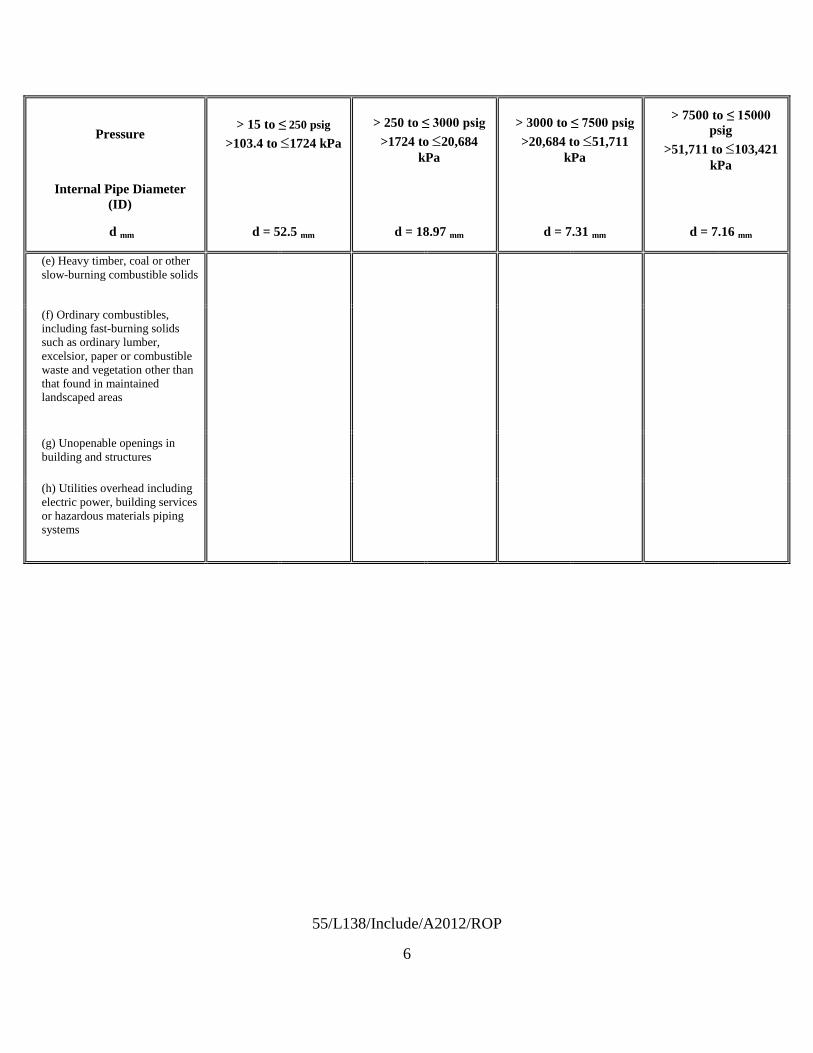
55/L138/Include/A2012/ROP
6
Pressure > 15 to ≤ 250 psig
>103.4 to ≤1724 kPa > 250 to ≤ 3000 psig
>1724 to ≤20,684 kPa
> 3000 to ≤ 7500 psig >20,684 to ≤51,711
kPa
> 7500 to ≤ 15000 psig
>51,711 to ≤103,421 kPa
Internal Pipe Diameter (ID)
d mm d = 52.5 mm d = 18.97 mm d = 7.31 mm d = 7.16 mm
(e) Heavy timber, coal or other slow-burning combustible solids
(f) Ordinary combustibles, including fast-burning solids such as ordinary lumber, excelsior, paper or combustible waste and vegetation other than that found in maintained landscaped areas
(g) Unopenable openings in building and structures
(h) Utilities overhead including electric power, building services or hazardous materials piping systems

55/L138/Include/A2012/ROP
7
Table 10.3.2.1(b) Minimum Distance (D) from Outdoor Bulk Hydrogen Compressed Gas Systems to Exposures – By Maximum Pipe Sizea
Pressure > 15 to ≤ 250 psig >103.4 to ≤1724 kPa
> 250 to ≤ 3000 psig >1724 to ≤20,684 kPa
Exposuresb Exposuresb
Internal Pipe Diameter (ID) Group 1 Group 2 Group 3 Group 1 Group 2 Group 3
ID (in)
d (mm)
D = 0.231d D = 0.12584d -0.47126 D = 0.096d D = 0.738d D = 0.43616d -
0.91791 D = 0.307d
m ft m ft m ft m ft m ft m ft
0.2 5.1 1 4 0 1 0 2 4 12 1 4 2 5
0.3 7.6 2 6 0 2 1 2 6 18 2 8 2 8
0.4 10.2 2 8 1 3 1 3 7 25 4 12 3 10
0.5 12.7 3 10 1 4 1 4 9 31 5 15 4 13
0.6 15.2 4 12 1 5 1 5 11 37 6 19 5 15
0.7 17.8 4 13 2 6 2 6 13 43 7 22 5 18
0.8 20.3 5 15 2 7 2 6 15 49 8 26 6 20
0.9 22.9 5 17 2 8 2 7 17 55 9 30 7 23
1.0 25.4 6 19 3 9 2 8 19 62 10 33 8 26
1.1 27.9 6 21 3 10 3 9 21 68 11 37 9 28
1.2 30.5 7 23 3 11 3 10 22 74 12 41 9 31
1.3 33.0 8 25 4 12 3 10 24 80 13 44 10 33
1.4 35.6 8 27 4 13 3 11 26 86 15 48 11 36
1.5 38.1 9 29 4 14 4 12 28 92 16 52 12 38
1.6 40.6 9 31 5 15 4 13 30 98 17 55 12 41
1.7 43.2 10 33 5 16 4 14 32 105 18 59 13 43
1.8 45.7 11 35 5 17 4 14 34 111 19 62 14 46
1.9 48.3 11 37 6 18 5 15 36 117 20 66 15 49
2.0 50.8 12 39 6 19 5 16 37 123 21 70 16 51
2.1 53.3 12 40 6 20 5 17 39 129 22 73 16 54

55/L138/Include/A2012/ROP
8
Pressure > 3000 to ≤ 7500 psig >20,684 to ≤51,711 kPa
> 7500 to ≤ 15000 psig >51,711 to ≤103,421 kPa
Exposuresb Exposuresb
Internal Pipe Diameter (ID) Group 1 Group 2 Group 3 Group 1 Group 2 Group 3
ID (in)
d (mm)
D = 1.105d D= 0.68311d - 1.3123 D = 0.459d D = 1.448d D = 0.92909d -
1.6813 D = 0.602d
m ft m ft m ft m ft m ft m ft
0.2 5.1 6 18 2 7 2 8 7 24 3 10 3 10
0.3 7.6 8 28 4 13 3 11 11 36 5 18 5 15
0.4 10.2 11 37 6 18 5 15 15 48 8 25 6 20
0.5 12.7 14 46 7 24 6 19 18 60 10 33 8 25
0.6 15.2 17 55 9 30 7 23 22 72 12 41 9 30
0.7 17.8 20 64 11 36 8 27 26 84 15 49 11 35
0.8 20.3 22 74 13 41 9 31 29 97 17 56 12 40
0.9 22.9 25 83 14 47 10 34 33 109 20 64 14 45
1.0 25.4 28 92 16 53 12 38 37 121 22 72 15 50
1.1 27.9 31 101 18 58 13 42 40 133 24 80 17 55
1.2 30.5 34 111 20 64 14 46 44 145 27 87 18 60
1.3 33.0 36 120 21 70 15 50 48 157 29 95 20 65
1.4 35.6 39 129 23 75 16 54 51 169 31 103 21 70
1.5 38.1 42 138 25 81 17 57 55 181 34 111 23 75
1.6 40.6 45 147 26 87 19 61 59 193 36 118 24 80
1.7 43.2 48 157 28 92 20 65 63 205 38 126 26 85
1.8 45.7 51 166 30 98 21 69 66 217 41 134 28 90
1.9 48.3 53 175 32 104 22 73 70 229 43 142 29 95
2.0 50.8 56 184 33 110 23 77 74 241 46 149 31 100

55/L138/Include/A2012/ROP
9
a Linear interpolation of internal pipe diameters and distances between table entries is allowed. b For a list of exposures in each exposure group see Column 1 of Table 10.3.2.1(a).
10.3.2.2.1.1 Maximum Internal Diameter of Interconnecting Piping. The maximum internal diameter of the piping system used for interconnecting piping between the shutoff valve on any single storage container to the point of connection to the system source valve shall not be required to be in accordance with exceed the values shown in Table 10.3.2.1.2.1(a) when in accordance with and Table 10.3.2.1.2.1(b) for the pressure range indicated except as allowed by 10.3.2.2.1.1(B) or 10.3.2.2.1.1(C).
10.3.2.2.1* 10.3.2.2.1.1(E) Determination of Internal Diameter. The internal diameter of the piping system shall be determined by the diameter of the piping serving that portion of a storage array with content greater than 400 scf (11.3 m3). The piping system size used in the application of Tables 10.3.2.1.2.1(a) and or 10.3.2.1.2.1(b) shall be determined based on that portion of the system with the greatest maximum internal diameter.
A.10.3.2.2.1
For example, a 3000 psig (20,684 kPa) storage system that supplies a 6000 psig (41,369 kPa) compressor that directly feeds a process with less than 400 scf (11.3 m3) of intervening storage at a pressure of 6000 psig (41,369 kPa) or less is considered a 3000 psig (20,684 kPa) system. Conversely, a system with the primary storage of 3000 psig (20,684 kPa) might supply a compressor that in turn delivers hydrogen to intermediate storage with a quantity of greater than 400 scf (11.3 m3). (Note: Pressures given are gauge pressures.) The piping serving the intermediate storage system from a point of discharge on the compressor can have an internal diameter of less than that serving the primary storage system upstream of the compressor. Accordingly, each portion of the system must be analyzed with respect to the tabular distances. See the typical P&IDs shown in Figure A.3.3.12(a) through Figure A.3.3.12(f) for additional information in this regard.
A.10.3.2.2.1.1(E) Systems that employ compressors downstream of a bulk supply typically operate at higher pressures than that of the bulk supply. As a result, the diameter of the piping system can vary with the pressure. The use of a higher pressure rating or variation of internal diameters is not warranted unless there is a storage component with a hydrogen content that exceeds 400 scf (11.3 m3) located downstream of the primary storage source and upstream of the source valve. The volume of gas contained within the piping system is not included in determining the quantity in storage.
The use of Table 10.3.2.1.(b)2.1.1(B) is based on the maximum internal diameter of the piping system over the range of pressures specified. In practice, it is common to maintain a consistent size of piping throughout the system; however, there might be cases where the ID of the piping system varies. In such cases, the piping with the largest internal diameter in the system is used to establish the system pipe size for the purposes of using the table, regardless of the length of the piping. It is not uncommon for portions of the system equipped with pressure gauges, pressure transducers, or other instrumentation to be served by small-diameter piping systems. However, the maximum internal diameter of the piping system will control the establishment of distance

55/L138/Include/A2012/ROP
10
for the exposures indicated. Pipe sizes are typically expressed in nominal terms as illustrated in Table A.10.3.2.2.1.1(E) below. This is compared with tubing in which the outside diameter (OD) is expressed in exact terms. Designers commonly use pipe schedule to specify the wall thickness for a given material based on the design conditions. Typical pipe sizes found in commerce include those shown in Table A.10.3.2.2.1.1(E).

55/L138/Include/A2012/ROP
11
Table A.10.3.2.2.1.1(E) Typical Pipe Sizes Pipe Schedules — Wall
Thickness (in.) Nominal
Pipe Size (in.)
O.D. (in.) 40 80 XH XXH
¼ 0.540 0.088 0.119 0.119 — 3/8 0.675 0.091 0.126 0.126 — ½ 0.840 0.109 0.147 0.147 0.294 ¾ 1.050 0.113 0.154 0.154 0.308 1 1.315 0.133 0.179 0.179 0.358
1¼ 1.660 0.140 0.191 0.191 0.382 1½ 1.900 0.145 0.200 0.200 0.400 2 2.375 0.154 0.218 0.218 0.436
2½ 2.875 0.203 0.276 0.276 0.552 3 3.500 0.216 0.300 0.300 0.600
3½ 4.000 0.226 0.318 0.318 0.636 4 4.500 0.237 0.337 0.337 0.674
XH = extra heavy; XXH = extra extra heavy. Note: Standard pipe schedule or pipe size as listed by ANSI/ASME B36.10M, Welded and Seamless Wrought Steel Pipe, and API Spec 5L, Specification for Line Pipe.
To determine internal diameter (ID) of a selected pipe size, multiply by 2 the wall thickness for the selected schedule and subtract the result from the outside diameter (OD): ID = OD - (2 × wall thickness) For example, for 2 in. Schedule 40 pipe: Wall thickness = 0.154 in.; OD = 2.375 in. Then: ID = 2.375 - (2 × 0.154) = 2.067 in. When tubing is used in lieu of pipe, the OD of the tubing is designated in inches (e.g., ¼, 3/8, 1/2, 1, 1¼, 1½, 2), and the tubing is manufactured to those specific dimensions. Tube wall thickness is determined based on the working pressure and materials of construction. The calculation of internal diameter is the same as that used for conventional pipe: ID = OD - (2 × wall thickness) For example, for ¼ in. OD tubing, if the wall thickness is 0.049 in. and the OD is 0.250 in., then:

55/L138/Include/A2012/ROP
12
ID = 0.250 - (2 × 0.049) = 0.152 in.
10.3.2.2.1.1
10.3.2.2.1.1(C) The separation distance for piping systems with internal diameters less than those specified in Table 10.3.2.2.1(a) and Table 10.3.2.2.1(b) for the pressure range selected shall be allowed to be reduced with tabular distances determined based on the use of equations in Table 10.3.2.2.1.1(B).
(A) Shutoff Valves on the Source of Supply. When shutoff valves are not connected directly to the source of supply, all interconnecting piping between the source connection and points downstream shall be included in the determination of internal diameter for the piping system.
10.3.2.2.2 10.3.2.2.1.1 (D) Separation distances determined based on the use of piping systems with pipe ID greater than that indicated in Table 10.3.2.1(b) 10.3.2.2.1.1(B) shall be subject to review and approval by the AHJ.
A.10.3.2.2.2. The methodology used to determine the distances listed in Table 10.3.2.1(b) has been evaluated for piping up to and including internal diameters of approximately 3 inches (76 mm). The establishment of risk informed separation distances for piping systems with greater internal diameters are subject to a hazard analysis that demonstrates an equivalent level of risk under the provisions of Section 1.5.
10.3.2.3 * 10.3.2.2.1.1(F)* Determination of System Pressure. The system pressure shall be determined by the maximum operating pressure of the storage array with content greater than 400 scf (11.3 m3), irrespective of those portions of the system elevated to a higher pressure.
A.10.3.2.3 A.10.3.2.2.1.1(F) Portions of a system might operate at higher pressures than the bulk supply; however, those portions of the system do not require the use of a pressure rating higher than that of the bulk supply unless there is a storage component exceeding 400 scf (11.3 m3) downstream of the primary storage source and upstream of the source valve. The volume of gas contained within the piping system is not included when the quantity in storage is determined. For example, a 3000 psig (20,684 kPa) storage system that supplies a 6000 psig (41,369 kPa) compressor that directly feeds a process with less than 400 scf (11.3 m3) of intervening storage at a pressure of 6000 psig (41,369 kPa) or less is considered a 3000 psig (20,684 kPa) system.
10.3.2.4* 10.3.2.2.2* Reduction of Distance By Mitigation Means. A.10.3.2.4 A.10.3.2.2.2 Distances to assumed lot lines established for the purpose of determining exterior wall and opening protection should not be confused with lot lines that are property lines in the true sense of the definition, and distances to assumed lot lines can be disregarded in the application of Tables
A permit holder cannot exercise any right of control over the property of others, whether the ownership is public or private. In cases where the permit holder owns an adjacent lot or parcel, the separation from property lines assumes that the permit holder could transfer ownership of the
10.3.2.1.2.1(a) and 10.3.2.1.2.1(b). The lot lines specified in 10.3.2.2.2 are property lines used to separate one lot from another or to separate a property from a street or other public space.

55/L138/Include/A2012/ROP
13
adjacent property at some point, and therefore the requirements for property line separation should be observed.
10.3.2.4.1* 10.3.2.2.2 Passive Means. Except for distances to lot lines, operable building openings, air intakes, and overhead utilities, the distances to Group 1 and 2 exposures shown in Tables 10.3.2.1.2.1(a) and 10.3.2.1.2.1(b) shall not apply be permitted to be reduced by one-half and shall not apply to Group 3 exposures where fire barrier walls having a minimum fire resistance rating of 2 hours constructed in accordance with the following are located between the system and the exposure.
(1) Fire barrier walls shall have a minimum fire resistance rating of not less than 2 hours.
(2) The fire barrier wall shall interrupt the line of sight between the bulk hydrogen compressed gas system and the exposure.
(3) The configuration of the fire barrier shall allow natural ventilation to prevent the accumulation of hazardous gas concentrations.
(4) The number of fire barrier walls used to separate individual systems shall be limited to three. 10.3.2.2.4 Where fire barrier walls of three sides are used, the walls shall be in accordance with 11.3.2.2.4.
(5) Fire barrier walls shall be designed and constructed as a structure in accordance with the requirements of the building code without exceeding the specified allowable stresses for the materials of construction utilized. Structures shall be designed to resist the overturning effects caused by lateral forces due to wind, soil, flood and seismic events.
(6)* Table 10.3.2.2.1(a) note f. Where clearance is required between the bulk hydrogen compressed gas system and the barrier wall for the performance of service or maintenance related activities the a minimum horizontal clearance of 5 feet shall be provided between the structure and the system required for access for service-related activities.
(7) The fire barrier wall shall be either an independent structure or the exterior wall of the building adjacent to the storage or use area when the exterior building wall meets the requirements for fire barrier walls.
(8) The minimum wall height shall be not less than 8 ft (2.1 m).
(9) The minimum wall length shall project not less than 5 ft (1.5 m) horizontally beyond the most remote point of the system or the exposure.
A.10.3.2.4.1
As stated by Sandia National Laboratories researchers Houf, Schefer, and Evans in “Analysis of
A.10.3.2.2.3 The code has historically recognized that, in certain instances, fire barrier walls can serve as a means to reduce the limits of unacceptable consequences due to the release of hydrogen from high-pressure equipment. Testing other than that related to establish fire resistance of the fire barrier walls has not been documented. Researchers at Sandia National Laboratories have been investigating the use of fire barrier walls as a means of mitigation in the establishment of distances related to the installation of bulk gaseous hydrogen systems, and a technical paper has been presented detailing the early findings.

55/L138/Include/A2012/ROP
14
Barriers for Mitigation of Unintended Releases of Hydrogen,” the purpose of the Sandia study was to extend the available database on barrier walls as a hazard mitigation strategy and to provide technical data for risk-informed decisions in hydrogen codes and standards regarding barrier wall design and implementation. Additional research by Sandia’s Jeff LaChance in a paper titled “NFPA Mitigation Analysis” the focus of the research included testing to assess the effectiveness of various barrier designs in terms of the following:
(1) Deflecting jet flames
(2) Reducing the extent of the flammable cloud resulting from an unignited release
(3) Reducing the magnitude of the radiative heat flux produced by a jet flame from an ignited release
(4) Minimizing the amount of ignition overpressure produced from the barrier confinement
When the work is concluded, it is expected that the results will likely provide the basis for criteria for the proper configuration, design, and construction of such barriers in order that the walls do not create other hazards. The work to date has been limited; however, the results have been promising. Houf, Schefer, and Evans have determined that for the conditions investigated, 2000 psi (13.79 MPa) source pressure and a in. (3.175 mm) diameter round leak, the barrier configurations studied were found to (1) reduce horizontal jet flame impingement hazard by deflecting the jet flame, (2) reduce radiation hazard distances for horizontal jet flames, and (3) reduce horizontal unignited jet flammability hazard distances. For the one-wall vertical barrier and the three-wall barrier configurations examined in the tests, the simulations of the peak overpressure hazard from ignition were found to be approximately 5.8 psi (40 kPa) on the release side of the barrier and approximately 0.73 psi to 0.44 psi (5 kPa to 3 kPa) on the downstream side of the barrier.
As stated by Sandia National Laboratories researchers Houf, Schefer, and Evans in “Evaluation of Barrier Walls for Mitigation of Unintended Releases of Hydrogen,” the purpose of the Sandia study was to extend the available database on barrier walls as a hazard mitigation strategy and to provide technical data for risk-informed decisions in hydrogen codes and standards regarding barrier wall design and implementation. Additional analysis by Sandia (LaChance, Phillips and Houf) in a paper titled “Risk Associated with the Use of Barriers in Hydrogen Refueling Stations” provided insights on the effectiveness of various barrier designs in terms of the following:
(1) Deflecting jet flames
(2) Reducing the extent of the flammable cloud resulting from an unignited release
(3) Reducing the magnitude of the radiative heat flux produced by a jet flame from an ignited release
(4) Minimizing the amount of ignition overpressure produced from the barrier confinement
Houf, Schefer, and Evans have determined that for the conditions investigated, 2000 psi (13.79 MPa) source pressure and a 1/8 in. (3.175 mm) diameter round leak, the barrier configurations

55/L138/Include/A2012/ROP
15
studied were found to (1) reduce horizontal jet flame impingement hazard by deflecting the jet flame, (2) reduce radiation hazard distances for horizontal jet flames, and (3) reduce horizontal unignited jet flammability hazard distances. For the one-wall vertical barrier and the three-wall barrier configurations examined in the tests, the simulations of the peak overpressure hazard from ignition were found to be approximately 5.8 psi (40 kPa) on the release side of the barrier and approximately 0.73 psi to 0.44 psi (5 kPa to 3 kPa) on the downstream side of the barrier. Although an overpressure can be expected due to latent ignition of a flammable cloud the overpressure is expected to be limited to a localized area. Special designs for overpressure in addition to the structural loads imposed by the building code have not been required.
The function of the fire barrier wall is to protect the exposure from the system and not the converse. The code assumes that other factors will enter into locating any material or structure in proximity to the bulk hydrogen compressed gas system. For example, if a property or lot line is involved opposite the hydrogen installation the proximity of a building to be constructed on the lot line is regulated by the building code based on the type and occupancy of structure to be constructed.
Investigation is continuing into the parameters for the construction of fire barrier walls. In the interim, a risk-informed approach to the establishment of distance has been introduced into Chapter 10 of this code. The Industrial and Medical Gases Technical Committee recognizes that previous editions of the code have allowed the use of fire barrier walls as a mitigation method. Until such time as the investigation by Sandia National Laboratories or others has been completed, 10.3.2.2.3 provides for the use, in limited cases, of fire barrier walls to mitigate effects on the downstream side of the wall by allowing a reduction of one-half of the separation distance otherwise required through the use of the risk-informed tables.
The resultant distances should be measured from a point on the unexposed (or downstream side) of the fire-barrier wall to the exposure. For example, the 45 ft (14.0 m) distance to lot lines shown for a 3,000 psi gauge (20,684 kPa gauge) system using piping with a maximum internal diameter (ID) of 0.747 in. (18.97 mm) can be reduced to 22.5 ft (7.0 m) between the property line and the fire barrier wall.
The concept of limiting the use of barrier walls is an interim determination that augments the requirements now found in the risk-informed approach to the establishment of separation distances. The outcome of the scientific research underway will measure the effect of the mitigation provided by the walls and will bring a firmness to the fire barrier requirements. The importance of completing the research is that all the factors integral to the construction of fire barrier walls will have been established through the scientific process. The use of the scientific process is a fundamental precept established in the acceptance of the risk-informed approach.
10.3.2.2.3* The distances in (1), (2), (4), and (10) in Table 10.3.2.2.1(a) and Table 10.3.2.2.1(b) shall be permitted to be reduced by one-half where fire barrier walls having a minimum fire resistance rating of 2 hours are located between the system and the exposure.
10.3.2.4.2* Active Means. Active control systems that mitigate the risk of system leaks and failures can be used as a means to reduce separation distances where approved by the AHJ under the authority granted by Section 1.5.

55/L138/Include/A2012/ROP
16
A.10.3.2.4.2 To determine the acceptability of technologies, processes, products, facilities, materials, and uses attending the design, operation or use of such systems, the AHJ is authorized to require the owner or agent to provide, without charge to the jurisdiction, a technical opinion and report. The model fire prevention codes provide the authority for the AHJ to seek technical assistance from independent third parties with expertise in the matter to be reviewed at the submitter’s expense. The AHJ is authorized to require design submittals to be prepared by, and bear the stamp of, a registered design professional or professional engineer.
Active means of control could include a means to detect leakage or fire coupled with automatic system shut down.
Gas Detection. To utilize gas detection as a means of control the gas sensor would be placed at a point between the bulk hydrogen compressed gas system and the exposure. Gas detection systems may be limited in their ability to detect the presence of hydrogen in the open. The are most effective if the sensor is located within an enclosed space such as an equipment enclosure. If used, gas detection systems should be either listed or approved.
Flame Detection. Flame detection systems may include combination UV/IR detection systems and be installed in accordance with the requirements of NFPA 72.
Ultraviolet flame detectors typically use a vacuum photodiode Geiger–Muller tube to detect the ultraviolet radiation that is produced by a flame. The photodiode allows a burst of current to flow for each ultraviolet photon that hits the active area of the tube. When the number of current bursts per unit time reaches a predetermined level, the detector initiates an alarm.
A single wavelength infrared flame detector uses one of several different photocell types to detect the infrared emissions in a single wavelength band that are produced by a flame. These detectors generally include provisions to minimize alarms from commonly occurring infrared sources such as incandescent lighting or sunlight. An ultraviolet/infrared (UV/IR) flame detector senses ultraviolet radiation with a vacuum photodiode tube and a selected wavelength of infrared radiation with a photocell and uses the combined signal to indicate a fire. These detectors need exposure to both types of radiation before an alarm signal can be initiated. A multiple wavelength infrared (IR/IR) flame detector senses radiation at two or more narrow bands of wavelengths in the infrared spectrum. These detectors electronically compare the emissions between the bands and initiate a signal where the relationship between the two bands indicates a fire. [72, A.5.8.2]
10.3.2.5 Required Separation Distance For All Systems. Separation distances are required for bulk hydrogen compressed gas systems independent of system pressure or internal diameter of piping systems in accordance with the following:
(1) 10.3.2.3 Unloading connections on delivery equipment shall not be positioned closer to any of the exposures cited in 10.3.2.1.2.1(a) or 10.3.2.1.2.1(b) than the distances given for the storage system.
(2) Table 10.3.2.2.1(a) note g Equipment classified as meeting Class I, Division 2, Group B requirements of NFPA 70, National Electrical Code when the area is in

55/L138/Include/A2012/ROP
17
accordance with NFPA 497, Recommended Practice for the Classification of Flammable Liquids, Gases, or Vapors and of Hazardous (Classified) Locations for Electrical Installations in Chemical Process Areas.
(3) Table 10.3.2.2.1(a) note h Bulk hydrogen storage systems are allowed to integrate (co-locate) other nonliquefied flammable gas systems where the output of the system is designed to deliver a product in which the gases are mixed or blended for delivery into the user’s system. The minimum separation distance indicated requires a minimum separation between gaseous and liquid systems integrated into a single system where the liquid source is vaporized, compressed, and stored in the gaseous state shall be 15 feet.
(4) 10.3.1.2 Systems within 50 ft (15 m) of aboveground storage of all classes of flammable and combustible liquids shall be located on ground higher than such storage, except where dikes, diversion curbs, grading, or separating solid walls are used to prevent accumulation of these liquids under the system.
10.3.2.6 Hydrogen And Other Flammable Gas Blends. Bulk hydrogen compressed gas storage systems are allowed to integrate (co-locate) other nonliquefied flammable gas systems as a component of the hydrogen gas system without separation where the output of the system is designed to deliver a product in which the gases are mixed or blended for delivery into the user’s system.
Also, in support of A.10.3.2.4.1 add the following informational references to Annex H under Section H.2.2.
LaChance, J., Phillips, J., Houf, W., “Risk Associated with the Use of Barriers in Hydrogen Refueling Stations,” National Hydrogen Association Conference & Expo, Long Beach, California, May 3-6, 2010 W. Houf, R. Schefer, G. Evans, E. Merilo, and M. Groethe, “Evaluation Of Barrier Walls For Mitigation Of Unintended Releases Of Hydrogen,” International Journal of Hydrogen Energy, Vol. 35, Issue 10, May 2010, pp. 4758-4775.

Report on Proposals – June 2012 NFPA 55>7500 to =15000 psi – 26 ft
· Table 10.3.2.1(a) displays the “typical” sizes based on pressure. On the other hand Table 10.3.2.2(b) allows arapid assessment of pipe sizes in the field without the use of what might be viewed as cumbersome calculations. Oncean ID is determined the distances are easily estimated and verified.
_______________________________________________________________________________________________55- Log #9
_______________________________________________________________________________________________Thomas L. Allison, Savannah River Nuclear Solutions
Delete line 5 from table or explain the hazard that requires up to 45 ft separation from air intake.Hydrogen is lighter than air and rapidly disburses when released. Hydrogen is not toxic and occurs
naturally in the air we breath. A flammable mixture is obviously not the concern since smoking is permitted at over 25 ft.There seems to be no basis for the distances indicated in the table.
_______________________________________________________________________________________________55- Log #1
_______________________________________________________________________________________________William E. Hancock, Performance Design Technologies
Minimum distance requirements for the S.I. unit table are miscalculated. 15 feet is translated as5.04, 5.6, 3.64, 4.31, 4.13, or 4.7 meters. Please revise appropriately.
See above.
_______________________________________________________________________________________________55- Log #46
_______________________________________________________________________________________________Robert Wichert, FCHEA, and Chris Radley, Altergy
Remove limits associated with Note f “The minimum clearance between the structure and thesystem required for access for service related activities”. This limit is inconsistent with standard construction practicethat requires a 3’ maintenance clearance and also inconsistent with practical applications since some sides of thesystem do not require maintenance clearance.Delete Row (6) from both tables.Add additional note to both tables: Provide adequate maintenance clearance to fire walls and other structures in
accordance with manufacturer’s instructions.The imposition of a 5 ft maintenance clearance is not consistent with common construction practices
that normally require a three foot maintenance clearance to obstructions or to property lines. Three feet is sufficient tosatisfy standard building code language for maintenance clearance to switchgear and equipment. There is no reasonfor additional clearance requirements to be given in the standard. Additionally, the imposition of an all-around clearancerequirement is inconsistent with practical construction since maintenance requirements do not apply to all sides oftypical equipment. Requiring compliance with manufacturer’s instructions is sufficient.
57Printed on 1/6/2011

Report on Proposals – June 2012 NFPA 55_______________________________________________________________________________________________55- Log #47
_______________________________________________________________________________________________Robert Wichert, FCHEA, and Chris Radley, Altergy
Delete row (2) in both tables.Row (2) is not needed since row (1) provides more conservative separation distances to passersby.
Within a particular installation, those granted access are best regulated by the owners. Attempting to regulate access toservice personnel only, might exclude operators or owners who are rightly expected to have access to the equipment. Itis not unusual to have bundles of hydrogen tanks in welding shops where operators and others are in contact with thetanks. This has not been shown to be an unacceptable risk. Residential owners will also need access. If the intent isto have all bulk storage in a fenced enclosure, additional justification is required.
58Printed on 1/6/2011

Report on Proposals – June 2012 NFPA 55_______________________________________________________________________________________________55- Log #26
_______________________________________________________________________________________________Andrew Webb, European Industrial Gases Assn.
Revise 10.3.2.2.1.1, 10.3.2.2.1.1(B), 10.3.2.2.1.1(C), and 10.3.2.2.1.1(D) as follows:The maximum internal diameter of the piping
system used for interconnecting piping between the shutoff valve on any single storage container to the point ofconnection to the system source valve shall not exceed:- 8 mm for systems having a maximum inventory of less than 100 kg or a water volume of less than 3000 L- 55/SP0,46 (mm), SP being the service pressure expressed in MPa, for systems having a maximum inventory of more
than 100 kg and a water volume of more than 3000 L, the values shown in Table 10.3.2.2.1(a) and Table 10.3.2.2.1(b)for the pressure range indicated except as allowed by 10.3.2.2.1.1 (B) or 10.3.2.2.1.1 (C).
The separation distance for piping systems with internal diameters greater than thelimits specified in 10.3.2.2.1.1 those specified in Table 10.3.2.2.1(a) and Table 10.3.2.2.1(b) for the pressure rangeselected shall be permitted with tabular distances determined based on the use of equations in table 10.3.2.2.1.(B)Table 10.3.2.2.1(a) or Table 10.3.2.2.1(b) corrected by a multiplicative factor K calculated as follows:For systems having a maximum inventory of less than 100 kg or a water volume of less than 3000 L: K = ID/8For systems having a maximum inventory of more than 100 kg and a water volume of more than 3000 L: K = SP0,46 x
ID/55With :SP : System pressure expressed in MPaID : Maximum Internal diameter, expressed in mm(C) The separation distance for piping systems with internal diameters less than those specified in Table 10.3.2.2.1(a)
and Table 10.3.2.2.1(b) for the pressure range selected shall be allowed to be reduced with tabular distancesdetermined based on the use of equations in Table 10.3.2.2.1.1 (B).(D) Separation distances determined based on the use of Table 10.3.2.2.1.1(B) shall be subject to review and approval
by the AHJ.Delete Table 10.3.2.2.1.1(B) and replace Table 10.3.2.2.1(a) and Table 10.3.2.2.1(b) with the following:
***INSERT TABLE 55_L26_10.3.2.2.1.1(a)_R HERE***
a Three categories are defined for gaseous hydrogen systems according to water volume, service pressure, and storedquantity, as follows:Category 1: Stored quantity not greater than 100 kg AND System pressure not greater than 55 MPaCategory 2: Water volume not greater than 3000 L AND System pressure greater than 55 MPaCategory 3: Water volume greater than 3000 L AND Stored quantity greater than 100 kgb For each category, sub-categories are defined in function of the complexity level (CL) of the hydrogen system defined
by the total count of joints and valves the system includes, with valves counting as four joints.Joints and valves on piping having an internal diameter smaller than the maximum internal diameter of the hydrogen
system may be counted by applying an equivalence factor equal to the square of the ratio of diameters.Joints and valves on piping operating at a pressure lower than the system pressure may be counted by applying an
equivalence factor equal to the ratio of pressures.For Category 1 and Category 2 systems, the following sub-categories are defined :Simple (S) : CL <= 60Complex (C) : CL > 60For Category 3 systems, the following sub-categories are defined :Simple (S) : CL <= 45Complex (C) : CL > 45
***INSERT TABLE 10.3.2.2.1(b)***
59Printed on 1/6/2011

55/L26/Table 10.3.2.2.1(a)/R/A2012/ROP
S(ft)
C(ft)
S(ft)
C(ft)
S(ft)
C(ft)
(1) 7 10 10 17 13 17
(2) 7 10 10 17 13 17
(3)
10 17 13 23 27 27
10 17 13 23 27 27
5 5 5 5 5 5
(4)
13 20 17 27 23 33
10 17 13 23 27 27
(5) 13 20 17 27 23 33
(6) 5 5 5 5 5 5
(7) 5 7 5 10 10 13
(8) 17 17 17 17 17 17
(9) 7 10 10 17 13 17
(10) 7 10 10 17 13 17
(11) 7 10 8 13 27 27
(12) 7 10 8 13 27 27
(13) 7 10 8 13 27 27
(14) 7 10 8 13 27 27
(15) 7 10 8 13 27 27
(16) 7 10 8 13 27 27Heavy timber, coal or other slow burning combustible solids
Aboveground vents or exposed piping and components of flammable gas storage systems including other hydrogen systems below ground.Hazardous materials (other than flammable gases) storage below ground Physical hazard materials or Health hazard materialsHazardous materials storage (other than flammable gases) above ground. Physical hazard materials or Health hazard materialsOrdinary combustibles including fast burning solids such as ordinary lumber, excelsior, paper or combustible waste and vegetation other than that found in maintained landscaped
Utilities (overhead) including electric power, building services, or hazardous materials piping.Ignition sources such as open flames and welding
Parked cars
Flammable gas storage systems including other hydrogen systems above ground.
UnopenableFire-rated or non fire-ratedAir intakes (HVAC, compressors, other)
Fire barrier walls or structures used to shield the bulk system from exposures. Unclassified electrical equipment
Non combustible non-fire-rated construction
Fire rated construction with a fire resistance rating of not less than 2 hoursOpenings in buildings of fire-rated or non-fireratedconstruction (doors, windows and penetrations)Openable(a)Fire-rated or non fire-rated
Lot lines
Exposed persons other than those involved in servicing of the systemBuildings and Structures
Combustible construction
Exposure
Category 1a
(<= 55 Mpa & <= 100 kg)Category 2a
(> 55 Mpa & <= 3000L)Cat. 3a
(> 100kg & >3000L)
System Complexity System Complexity System Compexity

55/L26/Table 10.3.2.2.1(b)/R/A2012/ROP
S(m)
C(m)
S(m)
C(m)
S(m)
C(m)
(1) 2,0 3,0 3,0 5,0 4,0 5,0
(2) 2,0 3,0 3,0 5,0 4,0 5,0
(3)
3,0 5,0 4,0 7,0 8,0 8,0
3,0 5,0 4,0 7,0 8,0 8,0
1,5 1,5 1,5 1,5 1,5 1,5
(4)
4,0 6,0 5,0 8,0 7,0 10,0
3,0 5,0 4,0 7,0 8,0 8,0
(5) 4,0 6,0 5,0 8,0 7,0 10,0
(6) 1,5 1,5 1,5 1,5 1,5 1,5
(7) 1,5 2,0 1,5 3,0 3,0 4,0
(8) 5,0 5,0 5,0 5,0 5,0 5,0
(9) 2,0 3,0 3,0 5,0 4,0 5,0
(10) 2,0 3,0 3,0 5,0 4,0 5,0
(11) 2,0 3,0 2,5 4,0 8,0 8,0
(12) 2,0 3,0 2,5 4,0 8,0 8,0
(13) 2,0 3,0 2,5 4,0 8,0 8,0
(14) 2,0 3,0 2,5 4,0 8,0 8,0
(15) 2,0 3,0 2,5 4,0 8,0 8,0
(16) 2,0 3,0 2,5 4,0 8,0 8,0
Category 1a
(<= 55 Mpa & <= 100 kg)
System Complexity
Category 2a
(> 55 Mpa & <= 3000L)
System Complexity
Heavy timber, coal or other slow burning combustible solids
Aboveground vents or exposed piping and components of flammable gas storage systems including other hydrogen systems below ground.Hazardous materials (other than flammable gases) storage below ground Physical hazard materials or Health hazard materialsHazardous materials storage (other than flammable gases) above ground. Physical hazard materials or Health hazard materialsOrdinary combustibles including fast burning solids such as ordinary lumber, excelsior, paper or combustible waste and vegetation other than that found in maintained landscaped
Utilities (overhead) including electric power, building services, or hazardous materials piping.Ignition sources such as open flames and welding
Parked cars
Flammable gas storage systems including other hydrogen systems above ground.
UnopenableFire-rated or non fire-ratedAir intakes (HVAC, compressors, other)
Fire barrier walls or structures used to shield the bulk system from exposures. Unclassified electrical equipment
Non combustible non-fire-rated construction
Fire rated construction with a fire resistance rating of not less than 2 hoursOpenings in buildings of fire-rated or non-fireratedconstruction (doors, windows and penetrations)Openable(a)Fire-rated or non fire-rated
Lot lines
Exposed persons other than those involved in servicing of the systemBuildings and Structures
Combustible construction
Exposure
Cat. 3a
(> 100kg & >3000L)
System Compexity

Report on Proposals – June 2012 NFPA 55
Table 10.3.2.2.1 (b) Minimum Distance from Outdoor Gaseous Hydrogen Systems to Exposures (SI units)
a Three categories are defined for gaseous hydrogen systems according to water volume, service pressure, and storedquantity, as follows:Category 1: Stored quantity not greater than 100 kg AND System pressure not greater than 55 MPaCategory 2: Water volume not greater than 3000 L AND System pressure greater than 55 MPaCategory 3: Water volume greater than 3000 L AND Stored quantity greater than 100 kg
b For each category, sub-categories are defined in function of the complexity level (CL) of the hydrogen systemdefined by the total count of joints and valves the system includes, with valves counting as four joints.Joints and valves on piping having an internal diameter smaller than the maximum internal diameter of the hydrogen
system may be counted by applying an equivalence factor equal to the square of the ratio of diameters.Joints and valves on piping operating at a pressure lower than the system pressure may be counted by applying an
equivalence factor equal to the ratio of pressures.For Category 1 and Category 2 systems, the following sub-categories are defined :Simple (S) : CL <= 60Complex (C) : CL > 60For Category 3 systems, the following sub-categories are defined :Simple (S) : CL <= 45Complex (C) : CL > 45
In a risk informed approach, separation distance requirements should be in tune with the risk actuallyrepresented by a system with regards to the neighboring exposures, and reflect particular aversion for escalationscenarios threatening critical exposures such as occupied locations or storage of large amounts of flammable fluids.This is not the case of the safety distance requirements for bulk gaseous hydrogen systems of the current edition of
NFPA 55, as they are all based on the same leak size hypothesis (3% pipe section area leak) without regards toessential risk factors such as system complexity, nor consideration of exposure criticality.Furthermore, the resulting distances are very sensitively determined by the Maximum Internal Diameter, a parameter
of detail design which does not reflect alone the actual risk impact of a system on its environment, and which can varysignificantly between two systems which would otherwise not be seen as having largely differing risk impacts (such astube trailers).This raises the following problems :- The requirements and perceived risk diverge- The application of a reduced safety distance, which should be justified by a higher level of safety, is permitted simply
by modifying a detail design parameter (MID), a change that does not significantly improve the true level of safety. TheAHJ has little basis to judge whether this reduction is acceptable.- The rationale does not allow to take into account specific prevention and mitigation measures reducing the risk impact
of a system, and therefore the corresponding separation distance requirements.- The approach goes against standardization of lay-out requirements, as these are now determined by a detail design
parameter which varies between otherwise similar systems.- The approach requires detail design to be known before performing lay-out, whereas, often, site selection – which
depends on lay-out requirements - needs to be performed before detail design is completed. There is a likelihood thatthe equipment finally selected will not comply with the MID hypothesis used to predetermine the lay-out.- Changes to an installation (such as renewal of equipment) that happens to involve a pipe-diameter change that
objectively does not impact risk may no longer be possible.The proposal is based on a different rationale which allows to avoid the above problems :The revised separation distances result from the application of a leak size which is not constant, but which depends
both on the type of hydrogen system and on the nature of the exposure. The risk model determines the leak size to beused in function of1) the system leak frequency profile, reflected by system complexity and estimated in the risk model from the number
of joints and valves in the system ; the increased likelihood of leak resulting from higher complexity results in the choiceof a larger reference leak size.2) the criticality of the exposure : a more stringent risk criteria is applied for critical exposures, resulting in the selection
of a larger leak size hypothesis.This results in separation distances that are much more consistent with actual risk as far as it can be estimated.Furthermore, the proposal focuses on producing an expert checked table providing separation distances to be applied
directly as-is in almost all cases, simplifying the use of the code and supporting lay-out standardization.
60Printed on 1/6/2011

Report on Proposals – June 2012 NFPA 55Application of separation distances different from those in the table is only foreseen for systems having a maximum
internal diameter (small systems) or leak magnitude indicator (large systems) greater than the hypothesis used toproduce the standard table. In this case a multiplicative factor is applied to the reference distances to reflect the largerpotential leak size.No further validation by the AHJ is therefore required.The statistical data source and the consequence model used to produce the proposed revise distance table are the
same as those used previously.Note: Supporting material is available for review at NFPA Headquarters.
_______________________________________________________________________________________________55- Log #45
_______________________________________________________________________________________________Robert Wichert, FCHEA, and Chris Radley, Altergy
Provide these equations using standard US units (inches and feet).Some AHJs may be more familiar with feet and inches and may tend to enforce limits based on those
units.
_______________________________________________________________________________________________55- Log #48
_______________________________________________________________________________________________Robert Wichert, FCHEA, and Chris Radley, Altergy
Change all exponents to at most three significant figures using a conservative method. Change allnumerical values to at most three significant figures using a conservative method. Combine equation branches wherepossible to simplify the calculations. Use numerical values for “e”.
The current use of six significant digits in the formulas cannot be supported by the uncertainty of theunderlying data. A detailed analysis is necessary to establish formulas that are both supportable and conservative. Inmany instances, the difference between the given exponents and “1” is so small that differences in the end result areless than one percent for all reasonable arguments. The use of Euler's number, e, (2.718…) is not explained and couldbe better expressed as a numerical value to avoid confusion on the part of the AHJ.
_______________________________________________________________________________________________55- Log #49
_______________________________________________________________________________________________Robert Wichert, FCHEA, and Chris Radley, Altergy
Revise text to read as follows:10.3.2.2.2* Except for the separation distances to lot lines (1), operable building openings (4a), air intakes (5), and
overhead utilities (8), the distances in Table 10.3.2.2.1(a) and Table 10.3.2.2.1(b) shall not apply where fire barrier wallshaving a minimum fire resistance rating of 2 hours are located between the system and the exposure.10.3.2.2.3* The separation distances to lot linesin (1), exposed persons (2), building openings (4), and parked cars (10)
in Table 10.3.2.2.1(a) and Table 10.3.2.2.1(b) shall be permitted to be reduced by one-half where fire barrier wallshaving a minimum fire resistance rating of 2 hours are located between the system and the exposure.
The current text is inconsistent. Consistency is preferable in this instance.
61Printed on 1/6/2011

Report on Proposals – June 2012 NFPA 55_______________________________________________________________________________________________55- Log #50
_______________________________________________________________________________________________Robert Wichert, FCHEA, and Chris Radley, Altergy
Delete sub-clause 10.3.2.2.4 entirely.The basis of the referenced sub-clause, 11.3.2.2.4, is to allow liquid hydrogen to flow and avoid
pooling. Such considerations do not apply to gaseous hydrogen.
_______________________________________________________________________________________________55- Log #109
_______________________________________________________________________________________________Larry L. Fluer, Fluer, Inc. / Rep. Compressed Gas Association
Revise text to read as follows:Where fire barrier walls of three sides are used, the walls shall be in accordance with 11.3.2.2.4. The fire
barrier wall shall not have more than two sides at 90 degrees (1.57 rad) directions or not more than three sides withconnecting angles of 135 degrees (2.36 rad).10.3.2.2.4.1* The connecting angles between fire barrier walls can be reduced to less than 135 degrees (2.36 rad) for
installations consisting of three walls when in accordance with 8.13.2.7.2.See Figure A.8.13.2.7.2.1 which addresses bulk cryogenic systems located in a courtyard. This figure
also applies to the case where the any or all of the three walls are constructed as fire barrier walls providing thedistances to walls constructed as fire barrier walls for exposure protection is not less than that required by Tables10.3.2.2.1 (a) or (b).
The proposed text adds clarification for systems that are surrounded by three walls when they areintended to be fire barrier walls. Figure A.8.13.2.7.2.1 illustrates a court where the 3 walls could be serving as firebarrier walls as long as the three walls do not create a confined space, they should be allowed just as if they were notfire barrier walls. The notes in the annex for A.8.13.2.7.2.1 and the corresponding figure specifically refer the user to thematerial specific chapters including statements referring to the requirements of distance tables in the material specificchapters.
62Printed on 1/6/2011

Report on Proposals – June 2012 NFPA 55_______________________________________________________________________________________________55- Log #51
_______________________________________________________________________________________________Robert Wichert, FCHEA, and Chris Radley, Altergy
Revise text to read as follows:10.4.1 Outdoor Locations.10.4.1.1 Where overhead cover is provided, it shall be in accordance with the provisions of 6.5.2. Weather and
security protection provided by an outdoor hydrogen enclosure shall meet the requirements of 10.4.1.1.1.10.4.1.1.1 Outdoor hydrogen enclosures10.4.1.1.1.1 Outdoor hydrogen enclosures shall be constructed of noncombustible or limited combustible materials.10.4.1.1.1.2 Ventilation shall be provided in accordance with the requirements of Section 6.15.10.4.1.1.1.3 The distance from the outdoor hydrogen enclosure and the structural supports to buildings, lot lines, public
ways means of egress to a public way or other exposures shall not be less than the distance required by 10.3.2.2 forOutdoor Storage.10.4.1.1.1.4 Where the outdoor hydrogen enclosure is constructed of noncombustible materials, reductions in the
separation distance shall be permitted based on the use of fire barrier walls where permitted in accordance with therequirements of 10.3.2.2.2 and 10.3.2.2.3.
Weather and security protection can be provided by an engineered outdoor enclosure meeting therequirements of 6.15 and 10.3.2.2 without requiring indoor construction. The current restrictions on overhead cover aretoo restrictive.
_______________________________________________________________________________________________55- Log #110
_______________________________________________________________________________________________Larry L. Fluer, Fluer, Inc. / Rep. Compressed Gas Association
Revise text to read as follows:Compressed gas containers and underground piping shall be protected from corrosion
in accordance with 7.1.10.9, 7.1.15 or 7.1.17 as applicable.
Protection from corrosion from contact with soil or surfaces that accumulate water is the subject ofSection 7.1.15. It should be included in 10.4.2.2 as an applicable cross reference as well.
_______________________________________________________________________________________________55- Log #52
_______________________________________________________________________________________________Robert Wichert, FCHEA, and Chris Radley, Altergy
Revise text to read as follows:10.4.2.4.1 Joints in the piping system shall be butt welded and 100 percent inspected using nondestructive testing
(NDT) methods in accordance with the requirements of ANSI/ASME B31.12 - 2008 Hydrogen Piping and Pipelines,ANSI/ASME B31.3, Process Piping, or other approved standards.
is the best guidance for hydrogen design.
63Printed on 1/6/2011

Report on Proposals – June 2012 NFPA 55_______________________________________________________________________________________________55- Log #31
_______________________________________________________________________________________________John J. Anicello, Airgas Inc.
Revise text to read as follows:10.4.4 Detached Buildings.10.4.4.1 Detached buildings shall be constructed of noncombustible or limited-combustible materials in accordance
with the requirements of Section 6.5.10.4.4.2 Ventilation shall be provided in accordance with the requirements of Section 6.15.10.4.4.2.1 Outlet openings shall be located at the high point of the room in exterior walls or the roof.10.4.4.2.2 Inlet and outlet openings shall each have a minimum total area of 1 ft2/1000 ft3 (1m2/305m3) of room
volume.10.4.4.2.3 Discharge from outlet openings shall be directed or conducted to the atmosphere.10.4.4.3* Explosion control shall be provided in accordance with the requirements of Section 6.8.10.4.4.4 Electrical equipment shall be in accordance with Article 501 of NFPA 70, National Electrical Code, for Class I,
Division 2 locations.10.4.4.5 Heating, if provided, shall be by steam, hot water, or other indirect means except that electrical heating shall
be permitted to be used if in compliance with 10.4.4.4.10.4.5 Hydrogen Gas Rooms.10.4.5.1 Floors, walls, and ceilings shall be constructed of noncombustible or limited-combustible materials in
accordance with the requirements of the building code.10.4.5.1.1 Interior walls or partitions shall have a fire resistance rating of not less than 2 hours, shall be continuous
from floor to ceiling, and shall be anchored to resist movement.10.4.5.1.2 Not less than 25 percent of the perimeter wall shall be an exterior wall.10.4.5.1.3 Openings to other parts of the building shall not be permitted.10.4.5.1.4 Windows and doors shall be in exterior walls only.10.4.5.2 Ventilation shall be as provided in Section 6.15.10.4.5.3 Explosion control shall be provided in accordance with the requirements of Section 6.8.10.4.5.4 There shall be no sources of ignition from open flames, electrical equipment, or heating equipment.10.4.5.5 Electrical equipment shall be in accordance with Article 501 of NFPA 70, National Electrical Code, for Class I,
Division 2 locations.10.4.5.6 Heating, if provided, shall be by steam, hot water, or indirect means except that electrical heating shall be
permitted to be used if in compliance with 10.4.5.5.
10.4.6 Indoor Hydrogen System Location.10.4.6.1 Hydrogen bulk systems located indoors shall be in accordance with this chapters 1 through 7 and 10.10.4.6.2 Indoor hydrogen bulk supply systems exceeding 15,000 scf shall be located in detached buildings in
accordance with Section 6.5.10.4.6.3 Ventilation shall be provided in accordance with the requirements of Section 6.15.10.4.6.3.1 Outlet openings shall be located at the high point of the room in exterior walls or the roof.10.4.6.3.2 Inlet and outlet openings shall each have a minimum total area of 1 ft2/1000 ft3 (1m2/305m3) of room
volume.10.4.6.3.3 Discharge from outlet openings shall be directed or conducted to the atmosphere.
10.4.6.1 Hydrogen systems of less than 3500 scf (99 m3) and greater than the MAQ, where located inside buildings,shall be located in the building so that the system will be as follows:(1) In a ventilated area in accordance with the provisions of Section 6.15(2) Separated from incompatible materials in accordance with the provisions of 7.1.10.2(3) A distance of 25 ft (7.6 m) from open flames and other sources of ignition(4) A distance of 50 ft (15 m) from intakes of ventilation, air-conditioning equipment, and air compressors(a) The distance shall be permitted to be reduced to 10 ft (3.1 m) where the room or area is protected by a listed
detection system per Article 500.7(K) of NFPA 70, National Electrical Code, and the detection system shuts down thefuel supply in the event of a leak that results in a concentration that exceeds 25 percent of the LFL.
(b) Isolation valves used to isolate the fuel supply shall be of a fail-safe design.(5) A distance of 50 ft (15 m) from other flammable gas storage
64Printed on 1/6/2011

Report on Proposals – June 2012 NFPA 55(6) Protected against damage in accordance with the provisions of 7.1.8.310.4.6.2 Systems Installed in One Room.10.4.6.2.1 More than one system of 3500 scf (99 m3) or less shall be permitted to be installed in the same room or
area, provided the systems are separated by at least 50 ft (15 m) or a full-height fire-resistive partition having a minimumfire resistance rating of 2 hours is located between the systems.10.4.6.2.2 The separation distance between multiple systems of 3500 scf (99 m3) or less shall be permitted to be
reduced to 25 ft (7.6 m) in buildings where the space betweenstorage areas is free of combustible materials and protected with a sprinkler system designed for Extra Hazard, Group 1in accordance with the requirements of Section 6.9.
None given.
_______________________________________________________________________________________________55- Log #111
_______________________________________________________________________________________________Larry L. Fluer, Fluer, Inc. / Rep. Compressed Gas Association
Revise text to read as follows:Prior to acceptance and initial operation, all piping installations shall be inspected and pressure tested in
accordance with ASME B31.12, and the ICCSection 705.
The IFGC points to ASME B31.3 piping code and does not provide any more specific requirements. Anew piping code, ASME B31.12, has now been issued for hydrogen piping and pipelines and provides more specificrequirements than ASME B31.3.
_______________________________________________________________________________________________55- Log #53
_______________________________________________________________________________________________Robert Wichert, FCHEA, and Chris Radley, Altergy
Revise text to read as follows:10.7.1 Unloading connections on delivery equipment shall not be positioned closer to any of the exposures cited in
Table 10.3.2.2.1(a) and Table 10.3.2.2.1(b) than the distances given for the storage system. Separation distances maybe reduced to those defined in Table 10.3.2.3.1.3 of NFPA 2 if an SAE J2600 nozzle is used on the unloadingconnection.
If an SAE J2600 nozzle is used to perform the cargo transport unloading, then the process is verysimilar to that defined in Sections 10.3.2.3, and 10.3.3.3.5 of NFPA 2 and their subparagraphs. The SAE J2600 nozzleprovides additional risk reduction and additional assurances that help to mitigate the risk of unloading. In addition,NFPA 58 Table 6.5.3 and Sections 6.5.4.4 and 6.26.5 allow closer setbacks for a heavier-than-air flammable gas.
65Printed on 1/6/2011

Report on Proposals – June 2012 NFPA 55_______________________________________________________________________________________________55- Log #112
_______________________________________________________________________________________________Larry L. Fluer, Fluer, Inc. / Rep. Compressed Gas Association
Revise text to read as follows:During transfer of hydrogen from cargo vehicles, the hand or emergency brake of the vehicle shall be set, and
chock blocks shall be used to prevent rolling of the vehicle from moving.
The term rolling could be inferred to mean turning over such as might be caused by high winds. Theintent is to stop movement of the wheels and landing gear.
_______________________________________________________________________________________________55- Log #113
_______________________________________________________________________________________________Larry L. Fluer, Fluer, Inc. / Rep. Compressed Gas Association
Revise text to read as follows:Each compressor shall be provided with a vent or relief device that will prevent over pressurizing of the
pump compressor under normal or upset conditions.
Editorial. Compressors are machines that are used to compress gases which typically results in raisingthe pressure. Pumps are normally associated with liquid systems. The term compressor should be used for consistencywithin the section.
_______________________________________________________________________________________________55- Log #114
_______________________________________________________________________________________________Larry L. Fluer, Fluer, Inc. / Rep. Compressed Gas Association
Revise text to read as follows:The pressure on the compressor discharge shall be monitored by a control system.
Excessive discharge pressures shall cause the compressor to shut down.
Simply monitoring the system is not sufficient. Without shutting the compressor off the system may becontinuously venting thereby creating potential vent stack fires. A requirement to shut down the compressor tells thedesigner what the control system is intended to perform.
66Printed on 1/6/2011

Report on Proposals – June 2012 NFPA 55_______________________________________________________________________________________________55- Log #115
_______________________________________________________________________________________________Larry L. Fluer, Fluer, Inc. / Rep. Compressed Gas Association
Revise text to read as follows:
Piping and tubing shall be in accordance with the requirements of ANSI/ASME B31.12,B31 .3,
Piping or tubing used at operating temperatures below -20°F (-29°C) shall be fabricated from materialsmeeting the impact test requirements of Chapter III of ANSI/ASME B31.12, B31.3,
when tested at the minimum operating temperature to which the piping will be exposed when in service.Joints in piping and tubing shall be in accordance with the requirements of ANSI/ASME B31.12,
B31 .3,
The new ASME B31.12 contains specific requirements for piping in hydrogen service. The forward tothe 2008 Edition of ASME contains, in pertinent part, the following information:“As a result of preliminary studies [conducted by ASME], it was concluded that gaps exist between existing piping and
pipeline codes and standards, and hydrogen infrastructure applications. A Project Team was formed under the B31Standards Committee to develop a new B31.12 Code for hydrogen piping and pipelines. The Project Team wassubsequently restructured under the B31 Standards Committee as a Section Committee.The first edition of the B31.12 Code applies to design, construction, operation, and maintenance requirements for
piping, pipelines, and distribution systems in hydrogen service. Typical applications are power generation, processplants, refining, transportation, distribution, and automotive filling stations. This Code is comprised of Part GR, GeneralRequirements, including common requirements referenced by all other parts; Part IP, Industrial Piping; and Part PL,Pipelines, including distribution systems. These Parts incorporate information specific to hydrogen service and eitherreference or incorporate applicable parts of ASME B31.3, Process Piping; ASME B31.1, Power Piping; ASME B31.8,Gas Transmission and Distribution Piping Systems; ASME B31.8S, Managing System Integrity of Gas Pipelines; andSection VIII, Division 3 of the ASME Boiler and Pressure Vessel Code, where appropriate.Material performance factors have been included to account for the adverse effects of hydrogen gas on the mechanical
properties of carbon and low alloy steels operating within the hydrogen embrittlement range. Many materials included inB31.3 have been omitted from B31.12’s tables due to their unsuitability for hydrogen service.”
67Printed on 1/6/2011

Report on Proposals – June 2012 NFPA 55_______________________________________________________________________________________________55- Log #116
_______________________________________________________________________________________________Larry L. Fluer, Fluer, Inc. / Rep. Compressed Gas Association
Revise text to read as follows:Connections downstream of the shutoff valve shall be in accordance with ANSI/ASME B31.12,
B31 .3,
The new ASME B31.12 contains specific requirements for piping in hydrogen service. The forward tothe 2008 Edition of ASME contains, in pertinent part, the following information:“As a result of preliminary studies [conducted by ASME], it was concluded that gaps exist between existing piping and
pipeline codes and standards, and hydrogen infrastructure applications. A Project Team was formed under the B31Standards Committee to develop a new B31.12 Code for hydrogen piping and pipelines. The Project Team wassubsequently restructured under the B31 Standards Committee as a Section Committee.The first edition of the B31.12 Code applies to design, construction, operation, and maintenance requirements for
piping, pipelines, and distribution systems in hydrogen service. Typical applications are power generation, processplants, refining, transportation, distribution, and automotive filling stations. This Code is comprised of Part GR, GeneralRequirements, including common requirements referenced by all other parts; Part IP, Industrial Piping; and Part PL,Pipelines, including distribution systems. These Parts incorporate information specific to hydrogen service and eitherreference or incorporate applicable parts of ASME B31.3, Process Piping; ASME B31.1, Power Piping; ASME B31.8,Gas Transmission and Distribution Piping Systems; ASME B31.8S, Managing System Integrity of Gas Pipelines; andSection VIII, Division 3 of the ASME Boiler and Pressure Vessel Code, where appropriate.Material performance factors have been included to account for the adverse effects of hydrogen gas on the mechanical
properties of carbon and low alloy steels operating within the hydrogen embrittlement range. Many materials included inB31.3 have been omitted from B31.12’s tables due to their unsuitability for hydrogen service.”
_______________________________________________________________________________________________55- Log #133
_______________________________________________________________________________________________Larry L. Fluer, Fluer, Inc. / Rep. Compressed Gas Association
Revise text to read as follows:Electrical wiring and equipment shall be in accordance with Table 11.2.6 and ,
.
****Insert Table 11.2.6 Here****
The existing wording raises a question as to what is meant by "storage equipment, excluding thepiping system downstream of the source valve". Does this mean "Storage container" or " Bulk system, excluding thepiping system downstream of the source valve"? The reference to "excluding the piping system downstream of thesource valve" implies that the "bulk system" is the intended point of control. NFPA 497 uses the term "StorageContainer" when applying electrical area classifications for liquid Hydrogen. Clarifying language has been added to thetable to identify the points of concern.
68Printed on 1/6/2011

55/L133/Tb 11.2.6/A2012/ROP
Table 11.2.6 Electrical Area Classification Location Division Extent of Classified Area
Points where connections to the hydrogen system are regularly made and disconnected
The bulk liquefied hydrogen system fill connection, pressure relief vent outlets or, other points on the system where hydrogen is vented to the atmosphere under the designed operating conditions
1 Within 3 ft (1 m) of the system fill connection system pressure relief vent outlets or other points of release when the system is operating as designed.
Storage equipment, excluding the piping system downstream of the source valve
2 Between 3 ft (1 m) and 25 ft (7.6 m) from the system fill connection, system pressure relief vent outlets or other points of release when the system is operating as designed.

Report on Proposals – June 2012 NFPA 55_______________________________________________________________________________________________55- Log #117
_______________________________________________________________________________________________Larry L. Fluer, Fluer, Inc. / Rep. Compressed Gas Association
Revise text to read as follows:Pressure on each pump and compressor discharge shall be monitored by the control
system.Excessive discharge pressures shall cause the pump or compressor to shut down.
Simply monitoring the system is not sufficient. Without shutting the pump or compressor off thesystem may be continuously venting thereby creating potential vent stack fires. A requirement to shut down the pump orcompressor tells the designer what the control system is intended to perform.
69Printed on 1/6/2011

Report on Proposals – June 2012 NFPA 55_______________________________________________________________________________________________55- Log #140
_______________________________________________________________________________________________Larry L. Fluer, Fluer, Inc.
The types of exposure represented in column 1 of the existing table for LH2 are proposed to becorrelated with the exposures listed in Table 10.3.2.2.1 for GH2 systems. A companion proposal has been issued toTable 10.3.2.2.1 separately.
****Insert Table 11.3.2.2 Here****
Revise Section 11.3.2.2.1 as follows:11.3.2.2.1 The distances in 1, 4, 6, 7, 8, 9,10 and 11 in Table 11.3.2.2 shall be permitted to be reduced by two-thirds,
but not to less than 5 ft (1.5 m), for insulated portions of the system.
The separation distances developed between GH2 systems and exposures has been the subject of amulti-year study by a joint task group staffed by members of the NFPA 2 and NFPA 55 Technical Committees. Theseparation distances for Bulk LH2 systems are currently under study. The charge for the group has been to validateand/or revise the required distances using a documented approach which results in a validated and/or revised distancebased on the use of scientific means.The work for LH2 is ongoing and consideration has been given to the use of quantity as a measure or basis for distancedetermination. Preliminary modeling has been performed by researchers at Sandia National Laboratories, and a basesystem has been developed in the form of a Piping and Instrumentation Diagram (P&ID) with typical pipe diametersconsidered. A survey has been sent to installers and maintainers of systems of this nature to assist in gatheringhydrogen specific data. At this juncture in the study further revisions or modification to the quantity approach ispremature, however, revisions have been proposed in an effort to align the list of exposures specified and/or to bespecified in Table 10.3.2.2.1. There are currently subtle differences in the table for LH2 that cannot be resolved at thisjuncture including distance to sprinklered buildings or buildings with sprinklered or noncombustible contents.The revisions proposed serve to align the exposure terminology and there have been no revisions made to any of the
separation distances listed. Exposures have now been grouped into three major groups and a companion proposal hasbeen submitted to Table 10.3.2.2.1 to group exposure in a similar manner. An annex note has been prepared forsubmittal with revisions to Table 10.3.2.2.1 that explains the “grouping” of exposures as follows. The proposedgroupings for exposure in Table 11.3.2.2 have been arranged to parallel those found in Table 10.3.2.2.1, however, theinclusion of a similar annex note for Table 11.3.2.2 would be premature given the fact that there have been no revisionsmade to any of the exposure distances which have yet to be validated and or revised based on thermal flux or othercriteria:
The exposures integral to Tables 10.3.2.1(a) and (b) have been arranged into groups based on similarrisks. The following thresholds are applicable to the exposures identified in each group.Group 1 Exposures. The distances specified are those required to reduce the radiant heat flux level to 500 Btu/hr · ft2
(1,577 W/m2) at the property line or the distance to a point in the unignited hydrogen jet where the hydrogen content isreduced to a 4 percent mole fraction (volume fraction) of hydrogen whichever is greater. In all cases the distancerequired to achieve a 4 percent mole fraction was the greater distance and used to establish the requirements.Group 2 Exposures. The distances specified are those required to reduce the radiant heat flux level to 1,500 Btu/hr · ft2
(4,732 W/m2) for persons employees exposed a maximum of 3 minutes.Group 3 Exposures. The distances specified are those required to reduce the radiant heat flux level to 6,340 Btu/hr · ft2
(20,000 W/m2) or the visible flame length for combustible materials, or a radiant heat flux level of 8,000 Btu/hr · ft2
(25,237 W/m2) or the visible flame length for non-combustible equipment. In both cases the visible flame length wasused to establish the requirements.
70Printed on 1/6/2011

55/L140/Tb 11.3.2.2/A2012/ROP 1
Table 11.3.2.2 Minimum Distance from Bulk Liquefied Hydrogen Systems to Exposures Total Liquefied Hydrogen Storage 39.7 gal to
3500 gal 150 L to 13,250 L
3501 gal to 15,000 gal
13,251 L to 56,781 L
15,001 gal to 75,000 gal
56,782 L to 283,906 L
Type of Exposure ft m ft m ft m Group 1
1. 11. Public ways, railroads, and property Lot lines
25 7.6 50 15 75 23
2. 3. Air compressor intakes or inlets for (heating air-conditioning or ventilating or air conditioning equipment (HVAC), compressors, other)
75 23 75 23 75 23
3. 2. Wall openings (a) Operable openings in buildings and structures 75 23 75 23 75 23 4. 9. Ignition sources such as open flames and welding
50 15 50 15 50 15
Group 2
5. 10. Places of public assembly 75 23 75 23 75 23
Group 3 6.1. Building or structure (a) Wall(s) adjacent to system Buildings constructed of noncombustible or limited-combustible materials
(1) Sprinklered building or structure or unsprinklered building or structure having noncombustible contents
5a 1.5 5a 1.5 5a 1.5
(2) Unsprinklered building or structure with combustible contents
(i) Adjacent wall(s) with fire resistance rating less than 3 hours
25 7.6 50 15 75 23
(ii) Adjacent wall(s) with fire resistance rating of 3 hours or greaterb
5 1.5 5 1.5 5 1.5
(b) Wall(s) adjacent to system constructed of combustible materials Buildings of combustible construction
(1) Sprinklered building or structure 50 15 50 15 50 15 (2) Unsprinklered building or structure 50 15 75 23 100 30.5 7. 6. Flammable gas storage or systems (other than hydrogen) above or below ground
50 15 75 23 75 23
8.5. Between stationary liquefied hydrogen containers
5 1.5 5 1.5 5 1.5
9.4. All classes of flammable and combustible liquids (above ground and vent or fill openings if below ground)c
50 15 75 23 100 30.5
10.7. Hazardous materials storage or systems including, liquid oxygen storage and other oxidizers, above or below ground
75 23 75 23 75 23
11.8. Heavy timber, coal or other slow-burning combustible solids
50 15 75 23 100 30.5
12.2. Wall openings (b) Inoperable Unopenable openings in buildings and structures
25 7.6 50 15 50 15
13.12. Inlet to underground sewers 5 1.5 5 1.5 5 1.5 14.13. Encroachment by Utilities overhead including electric power, lines building services or hazardous materials piping systems
(a) Horizontal distance from the vertical plane below the nearest overhead wire of an electric trolley, train, or bus line
50 15 50 15 50 15

55/L140/Tb 11.3.2.2/A2012/ROP 2
(b) Horizontal distance from the vertical plane below the nearest overhead electrical wire
25 7.5 25 7.5 25 7.5
(c) Piping containing other hazardous materials 15 4.6 15 4.6 15 4.6 a Portions of wall less than 10 ft (3.1 m) (measured horizontally) from any part of a system shall have a fire resistance rating of not less than 1 hour. b Exclusive of windows and doors. c The separation distances for Class IIIB combustible liquids shall be permitted to be reduced to 15 ft (4.6 m).

Report on Proposals – June 2012 NFPA 55_______________________________________________________________________________________________55- Log #134
_______________________________________________________________________________________________Larry L. Fluer, Fluer, Inc. / Rep. Compressed Gas Association
Revise text to read as follows:
11.* Public ways, railroads, and property linesd
A.Table 11.3.2.2 (11). The public way includes streets, alleys, sidewalks or similar rights of way that allow for freeaccess by the public. Railroads are typically placed on easements which allow for access by the public or travel wheremembers of the public are transported by the rail system. Lot lines (property lines) are those property lines betweenparcels and should not be construed to be the imaginary property lines that are drawn for the purposes of protecting theexterior walls of multiple buildings placed on the same lot or parcel. Railroad easements that are not accessible to thepublic other than by rail travel can be used as a means of spatial separation with the required separation beingmeasured between the hydrogen system and the nearest railroad track. It should be noted that in these cases, theaddition or relocation of track may result in an encroachment which will necessitate relocation of the hydrogen system atthe owner’s expense.
This table entry needs further clarification so that it applies to possible public exposures. The right ofway associated with a railroad are considered private property owned by the railroad, and in many cases would nottypically present a public exposure. In instances where there is no construction indicated other than the railsthemselves it is reasonable to measure the separation distance as that distance between the installed system and thenearest railroad track. In some instances natural boundaries on adjacent properties may be considered property lines ifno future buildings or structures can be built against them. In such cases an easement should be provided by theadjacent property owner and recorded in favor of the permittee or user of the hydrogen system. Such easements aresubject to the approval of the AHJ.
_______________________________________________________________________________________________55- Log #118
_______________________________________________________________________________________________Larry L. Fluer, Fluer, Inc. / Rep. Compressed Gas Association
Revise text to read as follows:For uninsulated portions of the system, the distances The distances in 1, 4, 6, 7, 8, and 11 in Table
11.3.2.2 shall be permitted to be reduced by the use of fire barrier walls having a fire resistance rating of not less than 2hours when constructed in accordance with 8.7.2.1 and 11.3.2.2.3.
NFPA 50B had a single paragraph listing which exposure distances could be reduced by using afirewall or the insulated portion of the system. That paragraph made it clear that using either a firewall or the insulatedpart of the system reduced only certain exposures. When the paragraph was rewritten in separate bullet items, section11.3.2.2.2 seemed to indicate that all distances could be reduced, but the intent of NFPA 50B was to reduce only certaindistances. The wording was also rewritten to clarify that firewalls can reduce the distances to insulated or uninsulatedportions of the system. Below is the text from NFPA 50B, 1999 (last) edition:
* The minimum distance in feet from liquefied hydrogen systems of indicated storage capacity located eitheroutdoors, in a separate building, or in a special room to any specified exposure shall be in accordance with Table 3-2.2.
71Printed on 1/6/2011

Report on Proposals – June 2012 NFPA 55_______________________________________________________________________________________________55- Log #119
_______________________________________________________________________________________________Larry L. Fluer, Fluer, Inc. / Rep. Compressed Gas Association
Revise text to read as follows:Unloading connections and pressure relief vents on delivery equipment shall not be positioned closer to any
of the exposures cited in Table 11.3.2.2 than the distances given for the storage system.
The delivery of LH2 from trailers/tankers can be by pumping or pressure transfer. In some caseshydrogen is released from relief vents on the delivery equipment. The exposures in Table 11.3.2.2 are fixed relative tothe tank. On the other hand the points of release from delivery equipment is variable based on the fact that the deliveryequipment utilizes flexible hose and the equipment is moveable. The design of delivery areas must give considerationto the position of delivery vehicles relative to exposures and the space allocated for delivery should be determinedaccordingly. A key element in consideration of the designated delivery space is the position of vents on the deliveryequipment relative to exposures. The design of delivery areas should be designed such that points of transfer as wellas points where vapor could be released from the delivery vehicle during delivery are positioned in a manner thatprovides separation between the points of potential release and exposures identified in the table.
_______________________________________________________________________________________________55- Log #120
_______________________________________________________________________________________________Larry L. Fluer, Fluer, Inc. / Rep. Compressed Gas Association
Revise text to read as follows:
Portable LH2 containers 39.7 gallons (150 liters) or less capacity of 50 gal (189 L) or less capacity located as allowedin Table 11.3.2.1 and in compliance with 11.3.1 where housed inside buildings, not located in a gas room, and exposedto other occupancies shall comply with the following minimum requirements:[balance to remain as printed]
By using 50 gallons or less as a threshold to trigger provisions in 55:11.3.3 the document creates aninconsistency. Containers with a volume of 39.7 gallons (150 L) or greater are considered to be bulk within the contextof 55: Chapter 11. By using a term 50 gallons or less a condition of non-bulk is created. A correlating change wassubmitted and accepted into NFPA 2 to address the inconsistency.
72Printed on 1/6/2011

Report on Proposals – June 2012 NFPA 55_______________________________________________________________________________________________55- Log #121
_______________________________________________________________________________________________Larry L. Fluer, Fluer, Inc. / Rep. Compressed Gas Association
Revise text to read as follows:User storage sites shall be fenced or otherwise secured and posted to prevent entry by unauthorized
personnel.The basis of this requirement is to prevent unauthorized personnel or those unfamiliar with gas storage
systems from tampering with the equipment. Where the LH2 is located in an area open to the general public, a commonpractice is to fence and lock the storage or use area, with access restricted to supplier and user personnel. When thestorage or use is located within the user’s secure area and is not accessible by the general public, it is not alwaysnecessary to fence or otherwise secure individual gas storage or use areas. Personnel access patterns may stillmandate that the system be fenced, as determined by the supplier and the user.
Administrative controls shall be allowed to be used to control access to individual storage, use, andhandling areas located in secure facilities not accessible by the general public.
As explained by the annex note, the primary purpose of security is to prevent tampering andunauthorized access by the general public. Many facilities are either fully fenced or otherwise provided with accesscontrol, such as walls whereby only the users of these materials are permitted access. The intent of the code was not torequire that any storage or use be under lock and key or that the security provided be such that storage or use by facilityemployees was hampered by security controls. It is reasonable to expect that facilities that are not accessible by thegeneral public have administrative procedures in place that directs the proper storage and use areas as well asspecifying how these materials will be allowed to be employed. New Section 11.4.1.4.1 does not mandate the use ofadministrative controls, but allows administrative controls to be used as a means to limit access. In areas not accessibleby the general public the user has a choice as to whether to provide physical barriers as a means of protection or tootherwise restrict access through the use of policies and procedures. This flexibility is required by the code to addresspractical application of these requirements.
73Printed on 1/6/2011

Report on Proposals – June 2012 NFPA 55_______________________________________________________________________________________________55- Log #123
_______________________________________________________________________________________________Larry L. Fluer, Fluer, Inc. / Rep. Compressed Gas Association
Revise text to read as follows:Hydrogen piping, valves, and fittings from the catalytic reforming–based hydrogen generation equipment
to hydrogen storage system shall conform to ASME/ANSI B31.12, B31 .3,
The new ASME B31.12 contains specific requirements for piping in hydrogen service. The forward tothe 2008 Edition of ASME contains, in pertinent part, the following information:“As a result of preliminary studies [conducted by ASME], it was concluded that gaps exist between existing piping and
pipeline codes and standards, and hydrogen infrastructure applications. A Project Team was formed under the B31Standards Committee to develop a new B31.12 Code for hydrogen piping and pipelines. The Project Team wassubsequently restructured under the B31 Standards Committee as a Section Committee.The first edition of the B31.12 Code applies to design, construction, operation, and maintenance requirements for
piping, pipelines, and distribution systems in hydrogen service. Typical applications are power generation, processplants, refining, transportation, distribution, and automotive filling stations. This Code is comprised of Part GR, GeneralRequirements, including common requirements referenced by all other parts; Part IP, Industrial Piping; and Part PL,Pipelines, including distribution systems. These Parts incorporate information specific to hydrogen service and eitherreference or incorporate applicable parts of ASME B31.3, Process Piping; ASME B31.1, Power Piping; ASME B31.8,Gas Transmission and Distribution Piping Systems; ASME B31.8S, Managing System Integrity of Gas Pipelines; andSection VIII, Division 3 of the ASME Boiler and Pressure Vessel Code, where appropriate.Material performance factors have been included to account for the adverse effects of hydrogen gas on the mechanical
properties of carbon and low alloy steels operating within the hydrogen embrittlement range. Many materials included inB31.3 have been omitted from B31.12’s tables due to their unsuitability for hydrogen service.”
_______________________________________________________________________________________________55- Log #122
_______________________________________________________________________________________________Larry L. Fluer, Fluer, Inc. / Rep. Compressed Gas Association
Revise text to read as follows:Pressurized portions of process exhaust system piping shall be in accordance with ANSI/ASME B31.12,
B31.3,
The new ASME B31.12 contains specific requirements for piping in hydrogen service. The forward tothe 2008 Edition of ASME contains, in pertinent part, the following information:“As a result of preliminary studies [conducted by ASME], it was concluded that gaps exist between existing piping and
pipeline codes and standards, and hydrogen infrastructure applications. A Project Team was formed under the B31Standards Committee to develop a new B31.12 Code for hydrogen piping and pipelines. The Project Team wassubsequently restructured under the B31 Standards Committee as a Section Committee.The first edition of the B31.12 Code applies to design, construction, operation, and maintenance requirements for
piping, pipelines, and distribution systems in hydrogen service. Typical applications are power generation, processplants, refining, transportation, distribution, and automotive filling stations. This Code is comprised of Part GR, GeneralRequirements, including common requirements referenced by all other parts; Part IP, Industrial Piping; and Part PL,Pipelines, including distribution systems. These Parts incorporate information specific to hydrogen service and eitherreference or incorporate applicable parts of ASME B31.3, Process Piping; ASME B31.1, Power Piping; ASME B31.8,Gas Transmission and Distribution Piping Systems; ASME B31.8S, Managing System Integrity of Gas Pipelines; andSection VIII, Division 3 of the ASME Boiler and Pressure Vessel Code, where appropriate.Material performance factors have been included to account for the adverse effects of hydrogen gas on the mechanical
properties of carbon and low alloy steels operating within the hydrogen embrittlement range. Many materials included inB31.3 have been omitted from B31.12’s tables due to their unsuitability for hydrogen service.”
74Printed on 1/6/2011

Report on Proposals – June 2012 NFPA 55_______________________________________________________________________________________________55- Log #124
_______________________________________________________________________________________________Larry L. Fluer, Fluer, Inc. / Rep. Compressed Gas Association
Revise text to read as follows:At mobile acetylene charging plants a deluge fire
sprinkler system in accordance with NFPA 13, extra hazard group 1 shall be installed in the areas occupied by trailers incharging or discharging stations. The deluge system shall be able to be activated automatically and also by manualactuator.
****Insert Figures 1 through 4 Here****
The IMG TC NFPA 51A task group has been tasked to integrate NFPA 51A into NFPA 55 and a draftChapter 15 will be submitted by the task group. Section 15.3.9.1 has been included in a proposal under development bythe IMG Chapter 15 task group. CGA has continued to study the issues surrounding the needs of fire protection formobile acetylene trailer charging and discharging stations and new information not considered by the IMG TC has beenfound that has a bearing on the type of fire protection system to be installed.Mobile acetylene trailer systems (MATS) are in use today as a means to transport or use large quantities of acetylene
gas. Acetylene trailers vary in size. A trailer may contain over 200 individual cylinders of acetylene with an aggregatecontent that can exceed 100,000 cubic feet. Typical trailers are approximately eight feet wide and range in length from15 to 50 feet although longer and shorter trailers may exist. The Department of Transportation (DOT) limits themaximum dimensions to 8.5 feet in width by 65 feet long.
_______________________________________________________________________________________________55- Log #125
_______________________________________________________________________________________________Larry L. Fluer, Fluer, Inc. / Rep. Compressed Gas Association
Revise text to read as follows:. The bulk system terminates at the source valve, which is commonly the point where
the gas supply, at service pressure, first enters the supply line or a piece of equipment that utilizes the gas or the liquid.The containers are either stationary or movable, and the source gas is stored as a compressed gas or cryogenic fluid.Bulk inert gas systems can be used to supply gas in either its compressed gaseous or liquefied form. Systems that
may be used to supply both gaseous and liquid forms are referred to as hybrid systems. The following bulk inert gassystems are typical of those in use:When the primary supply of the gas as stored is from a compressed gaseous source which is used in the compressed
and gaseous form, the bulk inert gas system is said to be a bulk inert compressed gas system.When the primary supply of the gas as stored is in a liquid form and the system is designed to transfer only liquid, the
system is said to be a bulk liquefied inert gas system.When the primary supply of the gas as stored is in a liquid form and the system is designed to transfer or store the gas
in a compressed gaseous form, with or without a feature that may also allow the subsequent transfer and use of liquid,the bulk inert gas system is said to be a hybrid bulk inert gas system.For the purposes of the application of the code, a hybrid system is viewed as a bulk liquefied inert gas system.
Guidance is needed to provide more comprehensive details in an informational note that informs theuser about liquid and gas systems that are commonly found in bulk inert gas systems. Bulk inert gas systems, unlikebulk hydrogen systems, are regulated under the use of a single term. Expanding the annex note to address the types ofsystems typically encountered will aid the user in understanding how the code is applied to any of the systemsmentioned within the context of a single umbrella term that describes the three most common system designs.
75Printed on 1/6/2011

Figure 1 – Large quantity of cylinders nested on a trailer Recent fires involving MATS at user sites during unloading operations were the subject of a report by the National Transportation Safety Board (NTSB) that was considered by the NFPA 51A technical committee during the ROP phase. The Compressed Gas Association (CGA) brought the NTSB report to the attention of NFPA’s Industrial and Medical Gases Technical Committee along with a request to revise the provisions of the document to coordinate NTSB recommendations with CGA’s G-1.6, Recommended Practices for Mobile Acetylene Trailer Systems which is an informational reference published in Annex B of NFPA 51A.

Figure 2. Acetylene gas fire at Southwest facility in Dallas.1
1 The pictures included in Figures 2 through 4 have been extracted from a report of the National Transportation Safety Board. The report was distributed to NFPA’s Industrial and Medical Gases Technical Committee prior to the ROP meeting for NFPA 51A. Special Investigation Report; Mobile Acetylene Trailer Accidents: Fire During Unloading in Dallas, Texas, July 25, 2007; Fire During Unloading in The Woodlands, Texas, August 7, 2007; and Overturn and Fire in East new Orleans, Louisiana, October 20, 2007, National Transportation Safety Board, Washington, D.C., NTSB/SIR-09/01, PB 2009-917002, Notation 8071, Adopted January 13, 2009, p.13.
Figure 3. Final phase of fire suppression at Southwest facility in Dallas.2

2 NTSB Report, NTSB/SIR-0901, p. 16
Figure 4. Dallas cylinder damage.3
3 NTSB Report, NTSB/SIR-0901, p. 16 CGA submitted the sole public proposal (ROP 51A-31 Log #16) and related comment (ROC 51A-8 Log #9) to address the need for fire protection for MAT systems to address concerns expressed by NTSB and CGA G-1.6. The IMG Technical Committee accepted ROC Item 51A-8 Log #9 in principle in part, but rejected CGA’s request for a deluge sprinkler system The IMG TC then crafted ROC Item 51A-9 Log #CC2 to require sprinkler protection designed for Extra Hazard Group 1 for MATS being charged or discharged either indoors or outdoors. The requirements for fire protection systems under the committee comment does not follow the NTSB recommendations, Department of Transportation recommendations or those found in CGA G-1.6 all of which advise requiring the use of deluge sprinkler systems. The IMG TC deliberations did not account for the fact that previous editions of NFPA 51A, for a period of twenty years or more, had required the use of NFPA 15, Standard for Water Spray Fixed Systems for Fire Protection. The actions taken in ROC Item 51A-9 CC#2 to require the installation of an Extra Hazard sprinkler system appear to have been premature falling short of establishing a clear set of requirements for a deluge system. The committee concluded that the requirements as written did not prohibit a user from installing a deluge system, but CGA has concluded that by not specifying the use of deluge systems for this unique material capable of producing a fast moving high challenge fire was a major shortcoming. CGA cast a negative ballot on the item with mutual opposition expressed by principals from FM Global and Underwriters Laboratories in the balloting process. The IMG TC has established an acetylene task group charged with integrating the requirements of NFPA 51A into a new Chapter 15 of NFPA 55 which is currently in the Annual 2012 Code Revision Cycle and during the 51A ROC meeting the committee expressed an intent of withdrawing NFPA 51A from publication. The task group will be including the developments in the evolution of NFPA 51A through the ROC draft for integration into NFPA 55 as a new Chapter 15 for that document. It is hoped that the ongoing work of the IMG committee will provide requirements that will clearly establish the need for the use of a deluge system, fixed spray sprinkler system or comparable means of fire protection. Prescriptive measures are also needed to clearly state that such systems are required for charging and discharging stations whether


Report on Proposals – June 2012 NFPA 55_______________________________________________________________________________________________55- Log #126
_______________________________________________________________________________________________Larry L. Fluer, Fluer, Inc. / Rep. Compressed Gas Association
Revise text to read as follows:. The bulk oxygen system terminates at the source valve, which is commonly the point
where oxygen, at service pressure, first enters the supply line or a piece of equipment that utilizes the oxygen gas orliquid. The containers are either stationary or movable, and the oxygen is stored as a compressed gas or cryogenic fluid.Bulk oxygen systems can be used to supply gas in either its compressed gaseous or liquefied form. Systems that may
be used to supply both gaseous and liquid forms are referred to as hybrid systems. The following bulk oxygen systemsare typical of those in use:When the primary supply of the gas as stored is from a compressed gaseous source which is used in the compressed
and gaseous form, the bulk oxygen system is said to be a bulk inert compressed gas system.When the primary supply of the gas as stored is in a liquid form and the system is designed to transfer only liquid, the
system is said to be a bulk liquefied oxygen system.When the primary supply of the gas as stored is in a liquid form and the system is designed to transfer or store the gas
in a compressed gaseous form, with or without a feature that may also allow the subsequent transfer and use of liquid,the bulk oxygen system is said to be a hybrid bulk oxygen systemFor the purposes of the application of the code, a hybrid system is viewed as a bulk liquefied oxygen system.
Guidance is needed to provide more comprehensive details in an informational note that informs theuser about liquid and gas systems that are commonly found in bulk oxygen systems. Bulk oxygen systems, unlike bulkhydrogen systems, are regulated under the use of a single term. Expanding the annex note to address the types ofsystems typically encountered will aid the user in understanding how the code is applied to any of the systemsmentioned within the context of a single umbrella term that describes the three most common system designs.
_______________________________________________________________________________________________55- Log #127
_______________________________________________________________________________________________Larry L. Fluer, Fluer, Inc. / Rep. Compressed Gas Association
Add new text to read as follows:Like other cryogenic liquids, liquid hydrogen is susceptible to heat leak. Adding heat to the fluid reduces the
net positive suction head (NPSH) to the pump and can reduce the level of sub-cooling or can cause the fluid to flash tovapor. Sub-cooled liquid is the ideal state for pumping liquid hydrogen. As the fluid saturates, the ability to pumpdecreases. The liquid suction and gas return piping to and from the pump typically is vacuum-jacketed piping.Vacuum-jacketed piping is most commonly used when liquid is to be transferred as it avoids the potential condensationof air and oxygen enrichment that can occur in piping systems that are insulated with conventional materials.In some cases the liquid may be transferred using un-insulated piping systems. Such systems must be designed in a
way that condensed air does not present a contact hazard to personnel or otherwise create a potential flammabilityhazard due to material contact and the presence of oxygen contained in the condensate.
The use of insulated material for hydrogen piping systems is not desirable in some cases.Vacuum-jacketed pipe is commonly used with vacuum acting as the insulating layer in contrast with materials that maybe inserted into an annulus formed by the use of a double walled piping system or by insulation placed around pipingused to transport liquid.In some cases un-insulated, un-jacketed pipe may be preferable. An informational note is proposed to alert the users
to the fact that vacuum jacketed piping systems will be encountered. The choice is that of the designer. The annexnote adds rationale as to why the fundamental statements are made in Section 11.2.3.6 so that users are betterinformed and that the hazards addressed by the requirements of the subsections that follow are better understood.
76Printed on 1/6/2011

Report on Proposals – June 2012 NFPA 55_______________________________________________________________________________________________55- Log #33
_______________________________________________________________________________________________Martin T. Gresho, FP2 Fire, Inc.
Retain the 1st paragraph of Annex G.2 and Table G.2 (a) and G.2(b). Relocate the material in therest of Annex G.2 to a new Annex Titles “Explanation of Methodology Utilized to Develop Separation Distances Tables10.3.2.2.1 (a) & (b)” Renumber remaining Annexes as needed.
As originally intended the OSHA material was to be in a separate Annex. The material in Annex G.2beyond the 1st paragraph does not relate to the OSHA tables but rather explains the development of the bulk GH2separation distance tables in Chapter 10. This material is intended to assist users of the Code in understanding how theChapter 10 separation distance tables were developed and is currently difficult to locate in Annex G. Creating twoseparate Annexes solves the problem.
77Printed on 1/6/2011


![Public Input No. 1-NFPA 13D-2015 [ Chapter 2 ] · 2016-11-03 · Public Input No. 1-NFPA 13D-2015 [ Chapter 2 ] ... 2011. ASME B16.4, Gray Iron Threaded Fittings, Classes 125 and](https://img.dokumen.tips/doc/110x75/5e7511f62a8e1021ca217ba3/public-input-no-1-nfpa-13d-2015-chapter-2-2016-11-03-public-input-no-1-nfpa.jpg)


![Public Input No. 13-NFPA 51A-2014 [ Chapter 2 ] Input No. 13-NFPA 51A-2014 ... 2011 edition 2014. ... ASME B31.3, Process Piping, 2008 2014. 2.3.3 ASTM Publications](https://img.dokumen.tips/doc/110x75/5adfd7cb7f8b9a8f298d78e6/public-input-no-13-nfpa-51a-2014-chapter-2-input-no-13-nfpa-51a-2014-2011.jpg)